90325-3010中文资料
华碩H310S R2.0电子电氣产品有害物质名称及含量说明标示说明书

備註:此產品所標示之環保使用期限,係指在一般正常使用狀況下。
產品詳情請掃描二維碼
三年質保
全國聯保
華碩產品質量保證卡
ห้องสมุดไป่ตู้
尊敬的華碩產品用戶:
首先非常感謝您選用華碩公司產品,讓我們有機會向您提供優質的服務。為了使我們的服務讓您更滿意,在購 買後請您認真閱讀此說明並妥善保存此質量保證卡。
四、 若經本公司判斷屬下列因素,則不屬於免費保修服務的範圍,本公司將有權利收取維修費用: A. 超過華碩提供的質保有效期的主板、顯卡產品。 B. 因遇不可抗拒外力(如:水災、火災、地震、雷擊、颱風等)或人為之操作使用不慎造成之損害。 C. 未按產品說明書條例的要求使用、維護、保管而造成的損壞。 D. 用戶擅自或請第三方人員自行檢修、改裝、變更組件、修改線路等。 E. 因用戶自行安裝軟件及設置不當所造成之使用問題及故障。 F. 本公司產品序列號標貼撕毀或無法辨認,塗改保修服務卡或與實際產品不符。 G. 其他不正常使用所造成之問題及故障。
保修說明注意事項: 一、 請將此質量保證卡下方的用戶資料填寫完整,並由最終直接經銷商加蓋印章,如果沒有加蓋印章,請找原購買
處補蓋以保障您的權益。請務必保留購買發票或複印件,否則華碩公司將以產品的出廠日期為參照進行保修。 二、 華碩公司對在中國大陸地區(不包括港澳台地區)發售的、經合法渠道銷售給消費者的華碩主板及顯卡產品實
有害物質
六價鉻 (Cr(VI))
○
○
多溴聯苯 (PBB)
○
○
多溴二苯醚 (PBDE)
○
○
本表格依據 SJ/T 11364 的規定編制。 ○:表示該有害物質在該部件所有均質材料中的含量均在 GB/T 26572 規定的限量要求以下。 ×:表示該有害物質至少在該部件的某一均質材料中的含量超出 GB/T 26572 規定的限量要求,然該部件仍符合歐盟指
NI cRIO-9035产品规范说明书
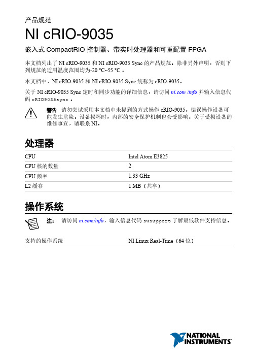
产品规范NI cRIO-9035嵌入式CompactRIO控制器、带实时处理器和可重配置FPGA本文档列出了NI cRIO-9035和NI cRIO-9035 Sync的产品规范。
除非另外声明,否则下列规范的适用温度范围均为-20 °C~55 °C 。
本文档中,NI cRIO-9035 和NI cRIO-9035 Sync 统称为 cRIO-9035。
关于NI cRIO-9035 Sync定时和同步功能的详细信息,请访问 /info并输入信息代码cRIO9035sync。
警告请勿尝试采用本文档中未提到的方式操作cRIO-9035。
错误操作设备可能发生危险。
设备损坏时,内部的安全保护机制也会受影响。
关于受损设备的维修事宜,请联系NI。
处理器CPU Intel Atom E3825CPU核的数量2CPU频率 1.33 GHzL2缓存 1 MB(共享)操作系统注:请访问/info,输入信息代码swsupport了解最低软件支持信息。
支持的操作系统NI Linux Real-Time(64位)软件要求应用程序软件LabVIEW LabVIEW 2014 SP1或更高版本,LabVIEW Real-Time模块2014 SP1或更高版本,LabVIEW FPGA模块2014 SP11或更高版本Eclipse Edition 2014或更高版本用于NI Linux Real-Time的C/C++ 开发工具2驱动程序软件NI-RIO设备驱动程序2015年2月或更高版本网络/以太网端口端口数量2网络接口10Base-T, 100Base-TX, 1000Base-T Ethernet兼容性IEEE 802.3通信速率10 Mbps, 100 Mbps, 1000 Mbps 自动调节线缆最大长度100 m/段RS-232串口最大波特率115,200 bps数据位5, 6, 7, 8停止位1, 2校验位奇、偶、标志、空格流控制RTS/CTS, XON/XOFF, DTR/DSRRI唤醒低电平(最大值)0.8 VRI唤醒高电平(最小值) 2.4 VRI过电压允许范围±24 V1使用扫描接口模式时无需安装 LabVIEW FPGA 模块。
商斯达射频微波光电产品目录说明书

SUNSTAR 商斯达微波光电公司 射频、微波、光纤、光电、通讯产品目 录更多产品请看本公司产品专用销售网站:欢迎来电查询购买商斯达产品或索取免费详细资料、设计指南和光盘;产品繁多,未能尽录,欢迎来电查询。
商斯达射频微波光电产品网:/商斯达中国传感器科技信息网:/商斯达工控安防网:/商斯达电子元器件网:/商斯达军工产品网:hrrp:///商斯达消费电子产品网:///商斯达实业研制科技产品网:/// 射频微波光电元器件销售热线:地址:深圳市福田区福华路福庆街鸿图大厦1602室电话:0755-******** 83397033 83398585 82884100MSN:邮编:518033 E-mail:QQ: 195847376深圳赛格展销部:深圳华强北路赛格电子市场2583号 电话:0755-******** 25059422 技术支持: 0755-******** 135********北京分公司:北京海淀区知春路132号中发电子大厦3097号TEL:82615020 FAX:上海分公司:上海市北京东路668号上海賽格电子市场D125号TEL:56703037 FAX:西安分公司:西安高新开发区20所(中国电子科技集团导航技术研究所)西安劳动南路88号电子商城二楼D23号TEL:Aavid ThermalloyABRACON CorporationAEPAeroflex INMETAeroflex KDI Resistor ProductsAmerican Tech Ceramics (ATC)AmphenolANADIGICSAnarenAnaren/RF PowerArcotronicsAvago TechnologiesBOMAR Interconnect Products, Inc.Cornell DubilierCrystek CorporationCTS CorporationDynex SemiconductorElectronic Devices, Inc.Emerson Network Power (formerly Johnson Components) Empower RF Systems, Inc.EPCOS F.W. BellFractusfree2moveFreescale Semiconductor, Inc. General ElectricGoreHoneywellHuber+SuhnerHVVIIllinois Capacitor, Inc.Infineon TechnologiesIQD Frequency ProductsJohanson ManufacturingLaird TechnologiesM/A-COM Technology Solutions Maxwell TechnologiesMicrosemiMicrosemi (Santa Clara)Mimix Broadband (formerly Celeritek) Mitsubishi ElectronicsNational ElectronicsNDKNEC Compound Semiconductors NitronexOhmitePacific MonolithicsPCTEL (Maxrad, Inc.)Peregrine Semiconductor PolyPhaser Corporation PowerexRadiallRadiotronixRaltronRES - IngeniumRF IndustriesRichardson Component Solutions Richardson Power Solutions Richardson System Solutions RiedonSDP Components, Inc. SemeLab, PlcSemikron Spectrum Advanced Specialty Products Spectrum MicrowaveST MicroelectronicsSV MicrowaveTeledyne CoaxTeledyne RelaysTensolite CDI/QMIToko AmericaTyco ElectronicsUnited Chemi-con, Inc.United Monolithic Semiconductors (UMS) Valpey FisherVincotechVishayWakefield Thermal SolutionsWanTcomWavecomWestcode Semiconductors, Inc.WJ CommunicationsMTI MilanoPacific MonolithicsMini-Circuits公司是1969年由 Harvey Kaylie先生创立的。
SFH3010中文资料
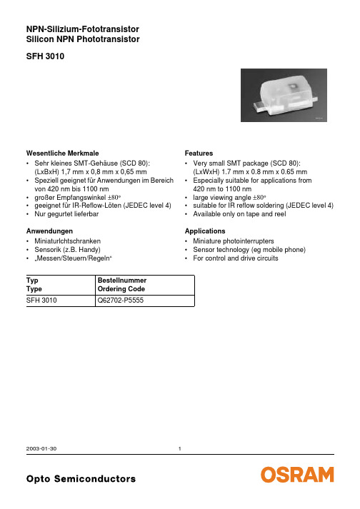
SFH 3010NPN-Silizium-FototransistorSilicon NPN Phototransistor 2003-01-301Wesentliche Merkmale•Sehr kleines SMT-Gehäuse (SCD 80):(LxBxH) 1,7 mm x 0,8 mm x 0,65 mm•Speziell geeignet für Anwendungen im Bereich von 420nm bis 1100nm •großer Empfangswinkel ±80°•geeignet für IR-Reflow-Löten (JEDEC level 4)•Nur gegurtet lieferbar Anwendungen•Miniaturlchtschranken •Sensorik (z.B. Handy)•…Messen/Steuern/Regeln“Typ Type Bestellnummer Ordering Code SFH 3010Q62702-P5555Features•Very small SMT package (SCD 80):(LxWxH) 1.7 mm x 0.8 mm x 0.65 mm •Especially suitable for applications from 420nm to 1100nm•large viewing angle ±80°•suitable for IR reflow soldering (JEDEC level 4)•Available only on tape and reel Applications•Miniature photointerrupters•Sensor technology (eg mobile phone)•For control and drive circuitsGrenzwerte Maximum RatingsBezeichnung Parameter SymbolSymbolWertValueEinheitUnitBetriebs- und Lagertemperatur Operating and storage temperature range Top; T stg– 40…+ 100°CKollektor-Emitterspannung Collector-emitter voltage VCEVCE(t<2min)1530VKollektorstrom Collector current IC15mAKollektorspitzenstrom, τ < 10 µs Collector surge current ICS75mAEmitter-Kollektorspannung Emitter-collector voltage VEC7VVerlustleistung, T A = 25 °C Total power dissipation Ptot130mWWärmewiderstand Sperrschicht - Umgebung bei Montage auf FR4 Platine, Padgröße je 16 mm2 Thermal resistance junction - ambient mounted on PC-board (FR4), padsize 16 mm2 each RthJA585K/W2003-01-3022003-01-303Kennwerte (T A = 25 °C, λ = 950 nm)Characteristics Bezeichnung ParameterSymbol Symbol Wert Value Einheit Unit Wellenlänge der max. Fotoempfindlichkeit Wavelength of max. sensitivityλS max 860nm Spektraler Bereich der Fotoempfindlichkeit S = 10% von S maxSpectral range of sensitivity S = 10% of S maxλ420 (1100)nmBestrahlungsempfindliche Fläche Radiant sensitive area A 0.02mm 2Abmessungen der Chipfläche Dimensions of chip area L ×B L ×W0.38×0.38mm ×mm Halbwinkel Half angleϕ± 80Grad deg.Kapazität CapacitanceV CE = 5 V, f = 1 MHz, E =0C CE1.3pFDunkelstrom Dark currentV CE = 20 V, E =0I CEO2 (≤50)nAFotostrom PhotocurrentE e = 0.5 mW/cm 2,V CE = 5 V I PCE>25µAAnstiegszeit/Abfallzeit Rise and fall timeI C = 1 mA, V CC = 5 V, R L = 1 k Ωt r ,t f7µsKollektrr-Emitter-Sättigungsspannung Collector-emitter saturation voltage I C = 10µAE e = 0.5 mW/cm 2, λ= 950nmV CEsat140mVDirectional CharacteristicsS= f (ϕ)rel2003-01-304Rel. Spectral Sensitivity,PhotocurrentPCE = (A),Dark CurrentCollector-Emitter CapacitanceDark CurrentTotal Power Dissipation2003-01-3052003-01-306Maßzeichnung Package OutlinesMa ße werden wie folgt angegeben: mm (inch) / Dimensions are specified as follows: mm (inch).Published by OSRAM Opto Semiconductors GmbH & Co. OHGWernerwerkstrasse 2, D-93049 Regensburg © All Rights Reserved.Attention please!The information describes the type of component and shall not be considered as assured characteristics.Terms of delivery and rights to change design reserved. Due to technical requirements components may contain dangerous substances. For information on the types in question please contact our Sales Organization.PackingPlease use the recycling operators known to you. We can also help you – get in touch with your nearest sales office.By agreement we will take packing material back, if it is sorted. You must bear the costs of transport. For packing material that is returned to us unsorted or which we are not obliged to accept, we shall have to invoice you for any costs incurred.Components used in life-support devices or systems must be expressly authorized for such purpose! Critical components 1 , may only be used in life-support devices or systems 2 with the express written approval of OSRAM OS.1A critical component is a component usedin a life-support device or system whose failure can reasonably be expected to cause the failure of that life-support device or system, or to affect its safety or effectiveness of that device or system.2Life support devices or systems are intended (a) to be implanted in the human body, or (b) to support and/or maintain and sustain human life. If they fail, it is reasonable to assume that the health of the user may be endangered.Package Epoxy, SmartLED (SCD 80)Colourcolourless, light diffusedPackage marking Collector。
场效应管hy3010中文参数
场效应管hy3010中文参数摘要:1.产康师满意度调查的背景和意义2.产康师满意度调查的具体内容3.产康师满意度调查的结果分析4.产康师满意度调查的结果应用5.产康师满意度调查的改进建议正文:一、产康师满意度调查的背景和意义随着我国经济的快速发展,产康师这一职业逐渐受到关注。
产康师是专门从事产妇产后康复工作的专业人员,他们为产妇提供产后健康指导和康复服务,帮助产妇尽快恢复身体机能。
为了更好地提高产康师的服务质量和工作效率,对产康师进行满意度调查评价具有重要意义。
二、产康师满意度调查的具体内容产康师满意度调查评价内容主要包括以下几个方面:1.服务质量:包括产康师的专业能力、服务态度、沟通技巧等。
2.服务效果:包括产康师对产妇的康复指导效果、产妇对产康师服务的满意程度等。
3.工作环境:包括产康师的工作环境、设备设施、材料供应等。
4.管理制度:包括产康师的工作时间、休假制度、薪酬福利等。
三、产康师满意度调查的结果分析通过对产康师满意度调查评价内容的分析,可以发现产康师服务的优点和不足之处,为管理者提供改进的依据。
同时,也可以了解产妇对产康师服务的需求和期望,为产康师提高服务质量提供参考。
四、产康师满意度调查的结果应用根据产康师满意度调查的结果,管理者可以采取以下措施:1.对表现优秀的产康师给予表彰和奖励,激发工作积极性。
2.对存在问题的产康师进行培训和指导,提高服务质量。
3.调整管理制度,优化工作环境,提高产康师的工作满意度。
4.根据产妇的需求和期望,调整产康师的服务内容和方式,提高服务质量。
五、产康师满意度调查的改进建议1.加大培训力度,提高产康师的专业能力和服务水平。
2.完善管理制度,保障产康师的合法权益,提高工作满意度。
3.注重产康师与产妇的沟通,提高服务质量和满意度。
DSO5000系列数字存储示波器用户手册(Ver0.9)
HCPL-9031中文资料

Agilent HCPL-9000/-0900, -9030/-0930,HCPL-9031/-0931, -900J/-090J,HCPL-901J/-091J, -902J/-092J High Speed Digital Isolators Data SheetDescriptionThe HCPL-90xx and HCPL-09xx CMOS digital isolators feature high speed performance and excellent transient immunity specifications. The symmetric magnetic coupling barrier gives these devices a typical pulsewidth distortion of 2ns, a typical propagation delay skew of 4ns and 100 Mbaud data rate, making them the industry ’s fastest digital isolators.The single channel digital isola-tors (HCPL-9000/-0900) features an active-low logic output enable.The dual channel digital isolators are configured as unidirectional (HCPL-9030/-0930) and bi-directional (HCPL-9031/-0931),operating in full duplex mode making it ideal for digital fieldbus applications.The quad channel digital isola-tors are configured as unidirec-Features•+3.3V and +5V TTL/CMOS compatible• 3 ns max. pulse width distortion • 6 ns max. propagation delay skew•15 ns max. propagation delay•High speed: 100 MBd •15 kV/µs min. common mode rejection•Tri-state output (HCPL-9000/-0900)•2500V RMS isolation•UL1577 and IEC 61010-1 approvedApplications•Digital fieldbus isolation •Multiplexed data transmission •Computer peripheral interface •High speed digital systems •Isolated data interfaces •Logic level shiftingtional (HCPL-900J/-090J), two channels in one direction and two channels in opposite direc-tion (HCPL-901J/-091J), and one channel in one direction and three channels in opposite direction (HCPL-902J/-092J).These high channel density make them ideally suited to isolating data conversion devices, parallel buses and peripheral interfaces.They are available in 8-pin PDIP,8-pin Gull Wing, 8-pin SOIC packages, and 16–pin SOIC narrow-body and wide-bodypackages. They are specified over the temperature range of -40°C to +100°C.CAUTION: It is advised that normal static precautions be taken in handling and assembly of this component to prevent damage and/or degradation,which may be induced by ESD.Selection GuideDevice Number Channel Configuration PackageHCPL-9000Single8-pin DIP (300 Mil)HCPL-0900Single8-pin Small OutlineHCPL-9030Dual8-pin DIP (300 Mil)HCPL-0930Dual8-pin Small OutlineHCPL-9031Dual, Bi-Directional8-pin DIP (300 Mil)HCPL-0931Dual, Bi-Directional8-pin Small OutlineHCPL-900J Quad16-pin Small Outline, Wide Body HCPL-090J Quad16-pin Small Outline, Narrow Body HCPL-901J Quad, 2/2, Bi-Directional16-pin Small Outline, Wide Body HCPL-091J Quad, 2/2, Bi-Directional16-pin Small Outline, Narrow Body HCPL-902J Quad, 1/3, Bi-Directional16-pin Small Outline, Wide Body HCPL-092J Quad, 1/3, Bi-Directional16-pin Small Outline, Narrow BodyOrdering InformationSpecify Part Number followed by Option Number (if desired). Examples:HCPL-90xx-xxxxxx:No option = 300 Mil PDIP-8 package, 50 units per tube.300 = Gull Wing Surface Mount Option, 50 units per tube.500 = Tape and Reel Packaging Option, 1000 units per reel.HCPL-09xx-xxxxxx:No option = SO-8 package, 100 units per tube.500 = Tape and Reel Packaging Option, 1500 units per reel.HCPL-90xJ-xxxxxx:No option = Wide Body SOIC-16 package, 50 units per tube.500 = Tape and Reel Packaging Option, 1000 units per reel.HCPL-09xJ-xxxxxx:No option = Narrow Body SOIC-16 package, 50 per tube.500 = Tape and Reel Packaging Option, 1000 units per reel.Pin DescriptionSymbol DescriptionVDD1Power Supply 1VDD2Power Supply 2IN X Logic Input Signal OUT X Logic Output Signal GND1Power Supply Ground 1GND2Power Supply Ground 2V OE Logic Output Enable (Single Channel), Active LowNC Not Connected Functional DiagramsTruth TableIN1V OE OUT1L L LH L HL H ZH H ZV DD1IN1NCGND1GND2OUT1V DD2V OEHCPL-9000/0900Single ChannelDual ChannelV DD1IN1IN2GND1GND2OUT2V DD2OUT1HCPL-9030/0930Quad ChannelV DD1GND1IN1IN2IN3IN4NCGND1GND2NCOUT4OUT3OUT2OUT1GND2V DD2HCPL-900J/-090JV DD1GND1IN1IN2OUT3OUT4NCGND1GND2NCIN4IN3OUT2OUT1GND2V DD2HCPL-901J/-091JV DD1GND1IN1IN2IN3OUT4NCGND1GND2NCIN4OUT3OUT2OUT1GND2V DD2HCPL-902J/-092JV DD1IN1OUT2GND1GND2IN2V DD2OUT1HCPL-9031/0931Package Outline DrawingsHCPL-9000, HCPL-9030 and HCPL-9031 Standard DIP PackagesHCPL-9000, HCPL-9030 and HCPL-9031 Gull Wing Surface Mount Option 300BSCDIMENSIONS INCHES (MILLIMETERS)LEAD COPLANARITY = 0.004 INCHES (0.10 mm)MIN MAXDIMENSIONS: INCHES (MILLIMETERS)MINMAXDIMENSIONS: INCHES (MILLIMETERS)MINMAXHCPL-0900, HCPL-0930 and HCPL-0931 Small Outline SO-8 PackageHCPL-900J, HCPL-901J and HCPL-902J Wide Body SOIC-16 Package0.092 (2.337)0.104 (2.642)0.011 (0.279)°DIMENSIONS: INCHES (MILLIMETERS)MINMAXHCPL-090J, HCPL-091J and HCPL-092J Narrow Body SOIC-16 Package0.054 (1.372)0.068 (1.727)0.010 (0.249)DIMENSIONS: INCHES (MILLIMETERS)MINMAXPackage CharacteristicsParameter Symbol Min.Typ.Max.Units Test ConditionsCapacitance (Input-Output)[1]CI-OpF f = 1 MHzSingle Channel 1.1Dual Channel 2.0Quad Channel 4.0Thermal ResistanceθJCT°C/W Thermocouple located at8-Pin PDIP150center underside of package 8-Pin SOIC240Package Power Dissipation P PD mW8-Pin PDIP1508-Pin SOIC150Notes:1.Single and dual channels device are considered two-terminal devices: pins 1-4 shorted and pins 5-8 shorted. Quad channel devices are consideredtwo-terminal devices: pins 1-8 shorted and pins 9-16 shorted.This product has been tested for electrostatic sensitivity to the limits stated in the specifications. However, Agilent recommends that all integrated circuits be handled with appropriate care to avoid damage. Damage caused by inappropriate handling or storage could range from performance degradation to complete failure.Insulation and Safety Related SpecificationsParameters Condition Min.Typ.Max.UnitsBarrier ImpedanceΩ||pF Single Channel>1014||3Dual Channel>1014||3Quad Channel>1014||7Creepage Distance (External)mm8-Pin PDIP7.0368-Pin SOIC 4.02616-Pin SOIC Narrow Body 4.02616-Pin SOIC Wide Body8.077Leakage Current240 VRMS 0.2µA60 HzAbsolute Maximum RatingsParameters Symbol Min.Max.Units Storage Temperature T S–55175°C Ambient Operating Temperature[1]T A–55125°C Supply Voltage V DD1, V DD2–0.57VInput Voltage VIN –0.5VDD1+0.5VVoltage Output Enable (HCPL-9000/-0900)V OE–0.5V DD2 +0.5VOutput Voltage V OUT–0.5V DD2 +0.5VOutput Current Drive I OUT10mALead Solder Temperature (10s)260°CESD 2 kV Human Body ModelNotes:1.Absolute Maximum ambient operating temperature means the device will not be damaged if operated under these conditions. It does notguarantee performance.Recommended Operating ConditionsParameters Symbol Min.Max.UnitsAmbient Operating Temperature T A–40100°CSupply Voltage V DD1, V DD2 3.0 5.5VLogic High Input Voltage V IH 2.4V DD1VLogic Low Input Voltage V IL00.8VInput Signal Rise and Fall Times tIR , tIF1µsThis product has been tested for electrostatic sensitivity to the limits stated in the specifications. However, Agilent recommends that all integrated circuits be handled with appropriate care to avoid damage. Damage caused by inappropriate handling or storage could range from performance degradation to complete failure.Electrical SpecificationsTest conditions that are not specified can be anywhere within the recommended operating range.All typical specifications are at T A=+25°C, V DD1 = V DD2 = +3.3V.Parameter Symbol Min.Typ.Max.Units Test ConditionsQuiescent Supply Current 1I DD1mA V IN = 0VHCPL-9000/-09000.0080.01HCPL-9030/-09300.0080.01HCPL-9031/-0931 1.5 2.0HCPL-900J/-090J0.0160.02HCPL-901J/-091J 3.3 4.0HCPL-902J/-092J 1.5 2.0Quiescent Supply Current 2I DD2mA V IN = 0VHCPL-9000/-0900 3.3 4.0HCPL-9030/-0930 3.3 4.0HCPL-9031/-0931 1.5 2.0HCPL-900J/-090J 5.58.0HCPL-901J/-091J 3.3 4.0HCPL-902J/-092J 3.0 6.0Logic Input Current I IN -1010µALogic High Output Voltage V OH V DD2–0.1 V DD2V I OUT = -20 µA, V IN=V IH0.8*V DD2 V DD2–0.5V I OUT = -4 mA, V IN=V IHLogic Low Output Voltage V OL 00.1V I OUT = 20 µA, V IN=V IL0.5 0.8V I OUT = 4 mA, V IN=V IL Switching SpecificationsMaximum Data Rate100110MBd C= 15 pFLClock Frequency fmax50MHzPropagation Delay Time to Logic t PHL1218nsLow OutputPropagation Delay Time toLogic t PLH1218nsHigh OutputPulse Width t PW10nsPulse Width Distortion[1]|PWD|23ns|t PHL– t PLH|Propagation Delay Skew[2]t PSK46nsOutput Rise Time (10–90%)t R24nsOutput Fall Time (10–90%)t F24nsPropagation Delay Enable to Output (Single Channel)High to High Impedance t PHZ35nsLow to High Impedance t PLZ35nsHigh Impedance to High t PZH35nsHigh Impedance to Low t PZL35nsChannel-to-Channel Skew t CSK23ns(Dual and Quad Channels)Common Mode Transient Immunity|CM H|1518kV/µs V cm = 1000V(Output Logic High or Logic Low)[3]|CM L|Notes:1.PWD is defined as |t PHL -t PLH|. %PWD is equal to the PWD divided by the pulse width.2.t PSK is equal to the magnitude of the worst case difference in t PHL and/or t PLH that will be seen between units at 25°C.3.CM H is the maximum common mode voltage slew rate that can be sustained while maintaining V OUT > 0.8V DD2. CM L is the maximum common modeinput voltage that can be sustained while maintaining V OUT < 0.8V. The common mode voltage slew rates apply to both rising and falling common mode voltage edges.This product has been tested for electrostatic sensitivity to the limits stated in the specifications. However, Agilent recommends that all integrated circuits be handled with appropriate care to avoid damage. Damage caused by inappropriate handling or storage could range from performance degradation to complete failure.Electrical SpecificationsTest conditions that are not specified can be anywhere within the recommended operating range.All typical specifications are at T A=+25°C, V DD1 = V DD2 = +5.0V.Parameter Symbol Min.Typ.Max.Units Test ConditionsQuiescent Supply Current 1I DD1mA V IN = 0VHCPL-9000/-09000.0120.018HCPL-9030/-09300.0120.018HCPL-9031/-0931 2.5 3.0HCPL-900J/-090J0.0240.036HCPL-901J/-091J 5.0 6.0HCPL-902J/-092J 2.5 3.0Quiescent Supply Current 2I DD2mA V IN = 0VHCPL-9000/-0900 5.0 6.0HCPL-9030/-0930 5.0 6.0HCPL-9031/-0931 2.5 3.0HCPL-900J/-090J8.012.0HCPL-901J/-091J 5.0 6.0HCPL-902J/-092J 6.09.0Logic Input Current I IN -1010µALogic High Output Voltage V OH V DD2–0.1 V DD2V I OUT= -20 µA, V IN=V IH0.8*V DD2 V DD2 –0.5V I OUT= -4 mA, V IN=V IHLogic Low Output Voltage V OL 00.1V I OUT= 20 µA, V IN=V IL0.5 0.8V I OUT= 4 mA, V IN=V IL Switching SpecificationsMaximum Data Rate100110MBd C= 15 pFLClock Frequency fmax50MHzPropagation Delay Time to Logic t PHL1015nsLow OutputPropagation Delay Time to Logic t PLH1015nsHigh OutputPulse Width t PW10nsPulse Width Distortion[1]|PWD|23ns|t PHL– t PLH|Propagation Delay Skew[2]t PSK46nsOutput Rise Time (10–90%)t R13nsOutput Fall Time (10–90%)t F13nsPropagation Delay Enable to Output (Single Channel)High to High Impedance t PHZ35nsLow to High Impedance t PLZ35nsHigh Impedance to High t PZH35nsHigh Impedance to Low t PZL35nsChannel-to-Channel Skew t CSK23ns(Dual and Quad Channels)Common Mode Transient Immunity|CM H|1518kV/µs V cm = 1000V(Output Logic High or Logic Low)[3]|CM L|Notes:1.PWD is defined as |t PHL -t PLH|. %PWD is equal to the PWD divided by the pulse width.2.t PSK is equal to the magnitude of the worst case difference in t PHL and/or t PLH that will be seen between units at 25°C.3.CM H is the maximum common mode voltage slew rate that can be sustained while maintaining V OUT > 0.8V DD2. CM L is the maximum common modeinput voltage that can be sustained while maintaining V OUT < 0.8V. The common mode voltage slew rates apply to both rising and falling common mode voltage edges.This product has been tested for electrostatic sensitivity to the limits stated in the specifications. However, Agilent recommends that all integrated circuits be handled with appropriate care to avoid damage. Damage caused by inappropriate handling or storage could range from performance degradation to complete failure.Applications InformationPower ConsumptionThe HCPL-90xx and HCPL-09xx CMOS digital isolators achieves low power consumption from the manner by which they transmit data across isolation barrier. By detecting the edge transitions of the input logic signal and con-verting this to a narrow current pulse, which drives the isolation barrier, the isolator then latches the input logic state in the output latch. Since the current pulses are narrow, about 2.5ns wide, the power consumption is indepen-dent of mark-to-space ratio and solely dependent on frequency.The approximate power supply current per channel is:I(Input) = 40(f/fmax)(1/4)mA where f = operating frequency,fmax =50MHz.Signal Status on Start-up and Shut DownTo minimize power dissipation,the input signals to the channels of HCPL-90xx and HCPL-09xx digital isolators are differenti-ated and then latched on the output side of the isolationbarrier to reconstruct the signal.This could result in an ambigu-ous output state depending on power up, shutdown and power loss sequencing. Therefore, the designer should consider the inclusion of an initialization signal in this start-up circuit.Bypassing and PC Board Layout The HCPL-90xx and HCPL-09xx digital isolators are extremely easy to use. No external interface circuitry is required because the isolators use high-speed CMOS IC technology allowing CMOS logicto be connected directly to the inputs and outputs. As shown in Figure 1, the only externalcomponents required for proper operation are two 47nF ceramic capacitors for decoupling the power supplies. For each capaci-tor, the total lead length between both ends of the capacitor and the power-supply pins should notexceed 20 mm. Figure 2 illustrates the recommended printed circuit board layout for the HCPL-9000or HCPL-0900. For data rates in excess of 10MBd, use of ground planes for both GND 1 and GND 2 is highly recommended.Figure 1. Functional Diagram of Single Channel HCPL-0900 or HCPL-0900.V DD1IN Note: C1, C2 = 47 nF ceramic capacitorsDD2OUT 1Figure 2. Recommended Printed Circuit Board Layout.C2V DD2OUT 1GND 2V DD1GND 1IN 1C1V OEHCPL-9000or HCPL-090011Propagation Delay, Pulse WidthDistortion and Propagation Delay Skew Propagation Delay is a figure of merit, which describes howquickly a logic signal propagates through a system as illustrated in Figure 3.The propagation delay from low to high, t PLH , is the amount of time required for an input signal to propagate to the output, causing the output to change from low to high. Similarly, the propagation delay from high to low, t PHL , is the amount of time required for the input signal to propagate to the output, causing the output to change from high to low.Figure 3. Timing Diagrams to Illustrate Propagation Delay, t PLH and t PHL .Figure 4. Timing Diagrams to Illustrate Propagation Delay Skew.VV V V Pulse Width Distortion, PWD, is the difference between t PHL and t PLH and often determines the maximum data rate capability of a transmission system. PWD can be expressed in percent bydividing the PWD (in ns) by the minimum pulse width (in ns)being transmitted. Typically, PWD on the order of 20–30% of the minimum pulse width is tolerable.Propagation Delay Skew, t PSK ,and Channel-to-Channel Skew,t CSK , are critical parameters to consider in parallel data trans-mission applications where synchronization of signals on parallel data lines is a concern.If the parallel data is being sent through channels of the digital isolators, differences in propaga-tion delays will cause the data to arrive at the outputs of the digital isolators at different times. If this difference in propagation delay is large enough, it will limit the maxi-mum transmission rate at which parallel data can be sent through the digital isolators.t PSK is defined as the difference between the minimum and maximum propagation delays,either t PLH or t PHL , among two or more devices which are operating under the same conditions (i.e.,the same drive current, supply voltage, output load, and operat-ing temperature). t CSK is defined as the difference between theminimum and maximum propaga-tion delays, either t PLH or t PHL ,among two or more channelswithin a single device (applicable to dual and quad channel de-vices) which are operating under the same conditions.As illustrated in Figure 4, if the inputs of two or more devices are switched either ON or OFF at the same time, t PSK is the difference between the minimum propaga-tion delay, either t PLH or t PHL , and the maximum propagation delay,either t PLH or t PHL .As mentioned earlier, t PSK , can determine the maximum parallel data transmission rate. Figure 5shows the timing diagram of a typical parallel data transmission application with both the clock and data lines being sent through the digital isolators. The figure shows data and clock signals at the inputs and outputs of the digital isolators. In this case, thedata is clocked off the rising edge of the clock.Figure 5. Parallel Data Transmission.DATADATAINPUTSCLOCKOUTPUTSCLOCKINPUTOUTPUT5 V CMOS2.5 V CMOS 0 VV OHV OLV OUTV IN/semiconductorsFor product information and a complete list of distributors, please go to our web site.For technical assistance call:Americas/Canada: +1 (800) 235-0312 or (408) 654-8675Europe: +49 (0) 6441 92460China: 10800 650 0017Hong Kong: (+65) 6271 2451India, Australia, New Zealand: (+65) 6271 2394Japan: (+81 3) 3335-8152(Domestic/International), or 0120-61-1280(Domestic Only)Korea: (+65) 6271 2194Malaysia, Singapore: (+65) 6271 2054Taiwan: (+65) 6271 2654Data subject to change.Copyright © 2002 Agilent Technologies, Inc.October 31, 20025988-5626ENPropagation delay skew repre-sents the uncertainty of where an edge might be after being sent through a digital isolator. Figure 5 shows that there will be uncer-tainty in both the data and clock lines. It is important that these two areas of uncertainty not overlap, otherwise the clock signal might arrive before all of the data outputs have settled, or some of the data outputs may start to change before the clock signal has arrived. From these considerations, the absoluteminimum pulse width that can be sent through digital isolators in a parallel application is twice t PSK .A cautious design should use a slightly longer pulse width toFigure 6. Timing Diagrams to Illustrate the Minimum Pulse Width, Rise and Fall Time, and Propagation Delay Enable to Output Waveforms for HCPL-9000 or HCPL-0900.ensure that any additional uncertainty in the rest of the circuit does not cause a problem.Figure 6 shows the minimum pulse width, rise and fall time,and propagation delay enable to output waveforms for HCPL-9000or HCPL-0900.t PW Minimum Pulse Width t PHZ Propagation Delay, High to High Impedance t PLZ Propagation Delay, Low to High Impedance t PZL Propagation Delay, High Impedance to Low t PZH Propagation Delay, High Impedance to High t R Rise Time t F Fall Time。
304-53-1900中文资料(molex)中文数据手册「EasyDatasheet - 矽搜」

参考 - 图纸编号
产品规格 销售图纸
产品规格PS-30453-0000(PDF) RoHS证书(PDF)
带状电缆/导线座 30453
一块
No 板,电缆支架
19
固有 纵
None
涤纶
1 Yes 0.062在 1.60 mm Bag 0.079在 2.00 mm N/A Yes No 无40°C至+ 85° C1.20毫米(.047“)最大. 26
芯片中文手册,看全文,戳
芯片中文手册,看全文,戳
进入角度 锁定插接部位
材料 - 树脂
行数
PCB保持力 推荐的PCB厚度(中) 推荐的PCB厚度(毫米)
包装形式
间距 - 接合界面(中) 间距 - 接合界面(毫米)
极性的插配件
PCB极性
可堆叠
表面焊接(SMC) 温度范围 - 操作
绝缘外径
线径规格AWG 电线/电缆形式
电
电流 - 每触点最大 电压 - 最大
带状电缆
2.25A 250V
PS-30453-0000 SD-30453-****
列
图片 - 仅供参考
欧 盟 RoHS指 令 ELV和 RoHS
标准
REACH SVHC
含有 SVHC:否
无卤 状态 尚未评估 需
中 国 RoHS指 令
搜索产品在这个系列
30453ቤተ መጻሕፍቲ ባይዱeries
配合带
N/A
可连接使用 面漆或实心线带状电缆
芯片中文手册,看全文,戳
上06/07/2010生成该文件
零件号: 现状: 说明:
0304531900
主动
俯仰线缆支架,立式,用于带状电缆,与偏振2.00毫米(.079“),19
THK交叉滚子轴承样本(中文)
( ) ( )
-GGX5••1$$ʷʷʷʷʷ ᮟ䕀
交叉滚柱轴环
A-861
静态安全系数
基本静额定负荷C0是指具有方向和大小都一定的静态负荷,其应满足使处于承受最大负荷状态下的滚柱 和滚动面之间的接触区域中心计算接触应力为 4000Mpa 的条件。(如果接触应力大于此数值 , 将影响旋 转。)此数值在尺寸表中以 C0 表示。当以静态或动态方式施加负荷时 , 必须考虑如下所示的静态安全系 数。
M =m1·gʷD1+m·2 gʷD2+(m·1 D1ʷ10-·3 ω 2+m2·D2ʷ10-3·ω 2)ʷH =100•9.807ʷ300+200•9.807ʷ150+ (100•300ʷ10-3•22+200•150ʷ10-3•22)ʷ200 =636420N·mm
'B 'S .EQ
ʷʽ
(N) (N) (N) (N·mm) (X0=1) (Y0=0.44) (mm)
ᕘ䋳㥋 ˄)U˅
ⶽ˄0˅
䕈䋳㥋 ˄)D˅ ⶽ ˄0˅
∴X=1,Y=0.45 因此,动态等价径向负荷(Pc)如下计算。
( ) ( ) 1$9'S E.Q : • 'Bʷ • ʷ/
如果fW=1.2,额定寿命按下式计算。因此额定寿命(L)为8.7ʷ108圈。
【高旋转精度】
因在垂直排列的滚柱间装有间隔保持器 , 防止了滚柱的侧倒或滚柱的相互摩擦 , 所以能防止旋转扭矩的 增加。另外 , 与以往使用铁板保持器的类型相比 , 不会发生滚柱的一方接触现象或锁死现象。即使被施 加予压,也能获得稳定的旋转运动。 并且 , 因内环或外圈是分割的构造 , 轴承间隙可调整。另外 , 即使被施加予压 , 也能获得高精度的旋转运 动。
NI cRIO-9035 商品说明书

SPECIFICA TIONSNI cRIO-9035Embedded CompactRIO Controller with Real-Time Processor and Reconfigurable FPGAThis document lists the specifications for the NI cRIO-9035 and NI cRIO-9035 Sync. The following specifications are typical for the -20 °C to 55 °C operating temperature range unless otherwise noted.In this document, the NI cRIO-9035 and NI cRIO-9035 Sync are inclusively referred to as the cRIO-9035.For more information about timing and synchronization capabilities of NI cRIO-9035 Sync, visit /info and enter the Info Code cRIO9035sync.Caution Do not operate the cRIO-9035 in a manner not specified in this document.Product misuse can result in a hazard. You can compromise the safety protectionbuilt into the product if the product is damaged in any way. If the product isdamaged, return it to NI for repair.ProcessorCPU Intel Atom E3825Number of cores2CPU frequency 1.33 GHzOn-die L2 cache 1 MB (shared)Operating SystemNote For minimum software support information, visit /info and enter theInfo Code swsupport.Note LabVIEW FPGA Module is not required when using Scan Interface mode.To program the user-accessible FPGA on the cRIO-9035, LabVIEW FPGA Moduleis required.Note C/C++ Development Tools for NI Linux Real-Time is an optional interfacefor C/C++ programming of the cRIO-9035 processor. Visit /info and enterInfo Code RIOCdev for more information about the C/C++ Development Tools forNI Linux Real-Time.cRIO-9035Supported operating system NI Linux Real-Time (64-bit)Software requirementsApplication softwareLabVIEW LabVIEW 2014 SP1 or later,LabVIEW Real-Time Module 2014 SP1 or later,LabVIEW FPGA Module 2014 SP1 or later, C/C++ Development Tools forEclipse Edition 2014 or laterNI Linux Real-TimeDriver software NI CompactRIO Device Drivers February2015 or latercRIO-9035 SyncSupported operating system NI Linux Real-Time (64-bit)Software requirementsApplication softwareLabVIEW LabVIEW 2016 or later,LabVIEW Real-Time Module 2016 or later,LabVIEW FPGA Module 2016 or later,Eclipse Edition 2016 or laterC/C++ Development Tools forNI Linux Real-TimeDriver software NI CompactRIO Device Drivers August 2016or laterNetwork/Ethernet PortNumber of ports2Network interface10Base-T, 100Base-TX, and1000Base-T EthernetCompatibility IEEE 802.3Communication rates10 Mbps, 100 Mbps, 1000 Mbpsauto-negotiatedMaximum cabling distance100 m/segment2| | NI cRIO-9035 SpecificationsRS-232 Serial PortMaximum baud rate115,200 bpsData bits5, 6, 7, 8Stop bits1, 2Parity Odd, Even, Mark, SpaceFlow control RTS/CTS, XON/XOFF, DTR/DSRRI wake maximum low level0.8 VRI wake minimum high level 2.4 VRI overvoltage tolerance±24 VRS-485/422 (DTE) Serial PortMaximum baud rate115,200 bpsData bits5, 6, 7, 8Stop bits1, 2Parity Odd, Even, Mark, SpaceFlow control XON/XOFFWire mode4-wire, 2-wire, 2-wire autoIsolation voltage60 VDC continuous, port to earth ground Note The RS-485 serial port ground and shield are not connected to chassisground. This isolation is intended to prevent ground loops and does not meet ULratings for safety isolation.Cable requirement Unshielded, 30 m maximum length (limited byEMC/surge)Note RS-485 is capable of 1.2 km (4,000 ft) length without surge limitation.NI cRIO-9035 Specifications| © National Instruments| 3USB PortsNumber of portsDevice ports 1 standard B connectorHost ports 2 standard A connectorsNote The USB device port is intended for use in device configuration, applicationdeployment, debugging, and maintenance.USB interface USB 2.0, Hi-SpeedMaximum data rate480 Mb/s per portMaximum current (USB host ports) 1 A (aggregate)Mini DisplayPortMaximum resolution2560 × 1600 at 60 HzSD Card SlotSD card support SD and SDHC standardsMemoryNonvolatile1SD removable (user supplied)Up to 32 GBSolid-state drive 4 GBNote Visit /info and enter the Info Code ssdbp for information about thelife span of the nonvolatile memory and about best practices for using nonvolatilememory.V olatileProcessor memoryDensity 1 GBType DDR3LMaximum theoretical data rate8.533 GB/s1 1 MB is equal to 1 million bytes. 1 GB is equal to 1 billion bytes. The actual formatted capacitymight be less.4| | NI cRIO-9035 SpecificationsData throughputSystem memory to SD removable10 MB/sstorage2Module slots to system memory20 MB/s, application- and system-dependent Reconfigurable FPGAFPGA type Xilinx Kintex-7 7K70TNumber of flip-flops82,000Number of 6-input LUTs41,000240Number of DSP slices(18 × 25 multipliers)Available block RAM4,860 kbitsNumber of DMA channels16Number of logical interrupts32Internal Real-Time ClockAccuracy200 ppm; 40 ppm at 25 °CCMOS Battery10 yearsTypical battery life with power applied topower connector7.8 yearsTypical battery life when stored attemperatures up to 25 °CTypical battery life when stored at5.4 yearstemperatures up to 85 °C2Consult the manufacturer specifications of your SD removable storage.NI cRIO-9035 Specifications| © National Instruments| 5Power RequirementsNote Some C Series modules have additional power requirements. For moreinformation about C Series module power requirements, refer to the C Seriesmodule(s) documentation.V oltage input range (measured at the cRIO-9035 power connector)V19 V to 30 VV29 V to 30 VMaximum power consumption46 WNote The maximum power consumption specification is based on a fully populatedsystem running a high-stress application at elevated ambient temperature and withall C Series modules and USB devices consuming the maximum allowed power. Typical standby power consumption 3.4 W at 24 VDC inputRecommended power supply100 W, 24 VDCTypical leakage current from secondary power input (V2) while system is powered from primary power input (V1)At 9 V0.4 mAAt 30 V 1.93 mACaution Do not connect V2 to a DC mains supply or to any supply that requires aconnecting cable longer than 3 m (10 ft). A DC mains supply is a local DCelectricity supply network in the infrastructure of a site or building.EMC ratings for inputs as described in IEC 61000V1Short lines, long lines, and DC distributednetworksV2Short lines onlyPower input connector4-position, 3.5 mm pitch, pluggable screwterminal with screw locks,Sauro CTF04BV8-AN000A6| | NI cRIO-9035 SpecificationsPhysical CharacteristicsIf you need to clean the cRIO-9035, wipe it with a dry towel.Tip For two-dimensional drawings and three-dimensional models of thecRIO-9035, visit /dimensions and search by module number.Weight (unloaded)2,250 g (4 lbs, 15 oz)Dimensions (unloaded)328.8 mm × 88.1 mm × 109.2 mm (12.94 in. ×3.47 in. ×4.30 in. )Screw-terminal wiringGauge0.5 mm 2 to 2.1 mm2 (20 AWG to 14 AWG)copper conductor wireWire strip length 6 mm (0.24 in.) of insulation stripped from theendTemperature rating85 °CTorque for screw terminals0.20 N · m to 0.25 N · m (1.8 lb · in. to2.2 lb · in.)Wires per screw terminal One wire per screw terminalConnector securementSecurement type Screw flanges providedTorque for screw flanges0.20 N · m to 0.25 N · m (1.8 lb · in. to2.2 lb · in.)Safety VoltagesConnect only voltages that are below these limits.V1 terminal to C terminal30 VDC maximum, Measurement Category I V2 terminal to C terminal30 VDC maximum, Measurement Category I Chassis ground to C terminal30 VDC maximum, Measurement Category I Measurement Category I is for measurements performed on circuits not directly connected to the electrical distribution system referred to as MAINS voltage. MAINS is a hazardous live electrical supply system that powers equipment. This category is for measurements of voltages from specially protected secondary circuits. Such voltage measurements include signal levels, special equipment, limited-energy parts of equipment, circuits powered by regulated low-voltage sources, and electronics.Caution Do not connect the cRIO-9035 to signals or use for measurements withinMeasurement Categories II, III, or IV.NI cRIO-9035 Specifications| © National Instruments| 7Note Measurement Categories CAT I and CAT O are equivalent. These test andmeasurement circuits are not intended for direct connection to the MAINS buildinginstallations of Measurement Categories CAT II, CAT III, or CAT IV.EnvironmentalTemperature (IEC-60068-2-1 and IEC-60068-2-2)Operating-20 °C to 55 °CStorage-40 °C to 85 °CCaution Failure to follow the mounting instructions in the user manual can causetemperature derating. Visit /info and enter Info Code criomounting formore information about mounting configurations and temperature derating. Ingress protection IP20Operating humidity (IEC 60068-2-56)10% RH to 90% RH, noncondensing Storage humidity (IEC 60068-2-56)5% RH to 95% RH, noncondensing Pollution Degree (IEC 60664)2Maximum altitude5,000 mIndoor use only.Hazardous LocationsU.S. (UL)Class I, Division 2, Groups A, B, C, D, T4;Class I, Zone 2, AEx nA IIC T4Canada (C-UL)Class I, Division 2, Groups A, B, C, D, T4;Class I, Zone 2, Ex nA IIC T4Europe (ATEX) and International (IECEx)Ex nA IIC T4 GcShock and VibrationTo meet these specifications, you must mount the cRIO-9035 system directly on a flat, rigid surface as described in the user manual, affix ferrules to the ends of the terminal wires, install an SD card cover (SD Door Kit, 783660-01), and use retention accessories for the USB host ports (NI Industrial USB Extender Cable, 152166-xx), USB device port (NI Locking USB Cable, 157788-01), and mini DisplayPort connector (NI Retention Accessory for Mini DisplayPort, 156866-01). All cabling should be strain-relieved near input connectors. Take 8| | NI cRIO-9035 Specificationscare to not directionally bias cable connectors within input connectors when applying strain relief.Operating vibrationRandom (IEC 60068-2-64) 5 g rms, 10 Hz to 500 HzSinusoidal (IEC 60068-2-6) 5 g, 10 Hz to 500 HzOperating shock (IEC 60068-2-27)30 g, 11 ms half sine; 50 g, 3 ms half sine;18 shocks at 6 orientationsSafety and Hazardous Locations StandardsThis product is designed to meet the requirements of the following electrical equipment safety standards for measurement, control, and laboratory use:•IEC 61010-1, EN 61010-1•UL 61010-1, CSA 61010-1•EN 60079-0:2012, EN 60079-15:2010•IEC 60079-0: Ed 6, IEC 60079-15; Ed 4•UL 60079-0; Ed 5, UL 60079-15; Ed 3•CSA 60079-0:2011, CSA 60079-15:2012Note For UL and other safety certifications, refer to the product label or the OnlineProduct Certification section.Electromagnetic CompatibilityThis product meets the requirements of the following EMC standards for electrical equipment for measurement, control, and laboratory use:•EN 61326-1 (IEC 61326-1): Class A emissions; Industrial immunity•EN 61000-6-2: Immunity•EN 55011 (CISPR 11): Group 1, Class A emissions•EN 55022 (CISPR 22): Class A emissions•EN 55024 (CISPR 24): Immunity•AS/NZS CISPR 11: Group 1, Class A emissions•AS/NZS CISPR 22: Class A emissions•FCC 47 CFR Part 15B: Class A emissions•ICES-001: Class A emissionsNote In the United States (per FCC 47 CFR), Class A equipment is intended foruse in commercial, light-industrial, and heavy-industrial locations. In Europe,Canada, Australia and New Zealand (per CISPR 11) Class A equipment is intendedfor use only in heavy-industrial locations.NI cRIO-9035 Specifications| © National Instruments| 9Note Group 1 equipment (per CISPR 11) is any industrial, scientific, or medicalequipment that does not intentionally generate radio frequency energy for thetreatment of material or inspection/analysis purposes.Note For EMC declarations and certifications, and additional information, refer tothe Online Product Certification section.CE ComplianceThis product meets the essential requirements of applicable European Directives, as follows:•2014/35/EU; Low-V oltage Directive (safety)•2014/30/EU; Electromagnetic Compatibility Directive (EMC)•94/9/EC; Potentially Explosive Atmospheres (ATEX)Online Product CertificationRefer to the product Declaration of Conformity (DoC) for additional regulatory compliance information. To obtain product certifications and the DoC for this product, visit / certification, search by model number or product line, and click the appropriate link in the Certification column.Environmental ManagementNI is committed to designing and manufacturing products in an environmentally responsible manner. NI recognizes that eliminating certain hazardous substances from our products is beneficial to the environment and to NI customers.For additional environmental information, refer to the Minimize Our Environmental Impact web page at /environment. This page contains the environmental regulations and directives with which NI complies, as well as other environmental information not included in this document.Waste Electrical and Electronic Equipment (WEEE)EU Customers At the end of the product life cycle, all NI products must bedisposed of according to local laws and regulations. For more information abouthow to recycle NI products in your region, visit /environment/weee.10| | NI cRIO-9035 SpecificationsBattery Replacement and DisposalBattery Directive This device contains a long-life coin cell battery. If you need toreplace it, use the Return Material Authorization (RMA) process or contact anauthorized National Instruments service representative. For more information aboutcompliance with the EU Battery Directive 2006/66/EC about Batteries andAccumulators and Waste Batteries and Accumulators, visit /environment/batterydirective.电子信息产品污染控制管理办法(中国RoHS)中国客户National Instruments符合中国电子信息产品中限制使用某些有害物质指令(RoHS)。
9032 自动调节或控制仪器及装置 品目注释

按照本章注释七的规定,本品目包括:(一)液体或气体的流量、液位、压力或其他变化量的自动控制仪器及装置或者温度自动控制仪器及装置,不论其是否依靠要自动控制的因素所发生的电现象来进行工作,这些仪器将自控因素调到并保持在一设定值上,通过持续或定期测量实际值来保持稳定,修正任何偏差;(二)电量自动调节器以及自动控制非电量的仪器或设备,依靠要控制因素所发生的电现象来进行工作,这些仪器将控制因素调到并保持在一设定值上,通过持续或定期测量实际值来保持稳定,修正任何偏差。
一、液体或气体的流量、液位、压力或其他变化量的自动控制仪器及装置或温度自动控制仪器及装置液体或气体的自动控制装置以及温度的自动控制装置是完整控制系统的部件,主要由以下装置构成:(一)测量要控制因素参量(槽罐中的压力或物位、室内温度等)的装置,在某些情形下,一个对参量变化十分敏感的元件(金属或双金属条、内装膨胀液体的膜盒或波纹管、浮子等)即可代替测量装置。
(二)将测量值与期望值比较,并使下述(三)款的装置产生相应动作的控制装置。
(三)启停或操作装置。
符合本章注释七(一)定义的液体、气体或温度自动控制设备由上述三部分装置组成,构成独立机构或构成符合本章注释三规定的功能机组。
某些仪器及装置不带有将测量值与期望值进行比较的装置,它们通过开关直接进行控制,例如,在达到设定值时打开开关。
③ 液体或金属棒的膨胀;④ 热电阻或热电偶。
双金属带恒温器的金属带固定在一个保护管或壳内;金属棒恒温器的金属棒装在保护管内;充蒸汽式或充液式恒温器的敏感元件由密封液体的褶皱膜片构成,或者是由膜片、毛细管及温包或弯管组成的系统。
(2)预置期望温度用的鼓筒、刻度盘或其他装置。
(3)触发或启动装置,按照采用的传递方式(机械式、伺服液动式、电动式)不同,其主要部件有:杠杆机构、弹簧等,以及阀或电气开关。
它们能发出控制信号或使诸如蒸汽或热水输送阀、锅炉燃烧器、空气调节装置、风扇等设备工作(通常是遥控的),以调节温度。
加尔文芯(Galvanic)ProTech903胶带分析仪说明书

The Only Tape Analyzer That Rivals Laboratory Sensitivity When Monitoring Sub-ppm H2S & Specialty CompoundsAdvanced Analysis•0.005 ppm Detection Limit•H2S & Total Sulfur Multi-ParameterHazardous Area Certified•Class I Division 2 and Division 1•ATEX / IECEx Zone 1Maintenance Friendly•30 Seconds to Alarm•Quick & Easy Excursion RecoveryExpanded Applications•Arsine for Ethylene Cracking Plants•Chlorine in Chlorine Absorption UnitsProTech903™ Tape Analyzer IntroductionProTech903™ is a process analyzer that measuresH2S, total sulfur, and other compounds in gas-phasesamples. ProTech903™ helps natural gas, refinery,and other industrial operators meet gas qualityrequirements and optimize process control.ProTech903™ uses a special tape method tomeasure gas compounds. Monitoring the rate ofchange of stain development on tape allowsProTech903™ to calculate the concentration.ProTech903™ is a 3rd-generation analyzer backed byGalvanic’s 40 years of field-proven experiencesupporting gas processing industries.0.005 ppm LDL for H2S and Specialty Compounds Lead-Acetate Tape MethodAfter sample is extracted, the gas is pressureregulated and filtered. Then the gas is humidifiedbefore coming in contact with the tape. A reactionoccurs causing a stain on the tape. The darker thestain, the less light is reflected. The rate of change ofthe stain is proportional to the concentration.Fast-Loop Key ComponentsSpecialty Gas CompoundsProTech903™ is best known for accuratelymeasuring H2S and Total Sulfur. However, theanalyzer can also be used to monitor non-sulfur gascompounds. Configurations are available for arsine,phosphine, phosgene, and chlorine.The analyzer configuration is customized for eachapplication. The humidifier will use deionized waterinstead of acetic acid, or will not include a humidifierat all. An alternate sensor block is used in someinstances. The lead-acetate tape will be substitutedby other specially formulated tapes.ProTech903™ offers a color card calibrationprocedure when measuring these compounds sincecalibration gas can be difficult to source.On-Board-Calibration Simplifies OperationHazardous Calibration Made EasyProTech903™ is the only tape analyzer that offerson-board-calibration (OBC) as a substitute for colorcard calibration. This system uses a calibration gasgenerator integrated with permeation tubes foraccurate on-demand calibration.In some cases, a carrier gas and temperaturecontroller are used along with a flow meter in orderto provide maximum accuracy.Engineering Drawing for Arsine & Phosphine Configuration (903W)Engineering Drawing for ATEX / IECEx Zone 1 Configuration (903CE Total Sulfur)Engineering Drawing for Class I Division 1 Configuration (903D1)Engineering Drawing for Class I Division 1 Configuration (903D1 Total Sulfur)Engineering Drawing for Class I Division 2 Configuration (903D2 Total Sulfur)Engineering Drawing for Class I Division 2 Configuration (903W)*****************|+1(403)252-8470| SAM-BMM-E30-ALL ProTech903 Brochure TI Rev . 3Specifications Subject to Change Without NoticeCompoundsHydrogen Sulfide, Total Sulfur, Arsine, Phosphine, Phosgene, Chlorine Ranges 100 ppb to 300 ppm Direct Feed / Above 300 ppm with Dilution ChamberAccuracy <0.5 ppm: ± 5% F.S. / 0.5 ppm to 1 ppm: ± 3.0% F.S. / >1 ppm to 50 ppm: ± 2.0% F.S. / >50 ppm: ± 2.5% F.S.Repeatability <0.5 ppm: ± 5% F.S. / 0.5 ppm to 1 ppm: ± 3.0% F.S. / >1 ppm to 50 ppm: ± 2.0% F.S. / >50 ppm: ± 2.5% F.S.Sensitivity ± 1% F .S .Method(s) Lead-Acetate Tape and Other Specialty Tapes for Non-H2S Applications Response Time 30 Seconds to AlarmCalibration Gas Cylinder, Color Card, On-Board-Calibration (OBC) Using Permeation Tubes Analog Outputs 6 x 4-20mA Outputs (Loop-Powered) Analog Inputs 3 x 4-20mA Inputs [RTD, 4-20mA, Transducer] Modbus RS232 or RS485 Digital Outputs 3 x SPDT Relays Digital Inputs 8 Discrete Inputs Remote GUI YesAnalyzer Display Monochrome LCD With Extendable KeypadAmbient Conditions 0 to 50°C [32° to 122°F] with 0 to 95% non-condensing relative humidity Power90 – 230 VAC, 10 – 32 VDC, or Solar Power Power Consumption 10 Watts [250 Watts for Total Sulfur]Total Sulfur Option Additional 9 kg [20 lbs.] and 381 mm [15”] WidthModel 903W903D2903D1903CEDimension 482 x 432 x 229 mm [19” x 17” x 9”] 86 x 838 x 318 mm[27” x 33” x 12.5”] 686 x 838 x 318 mm [27” x 33” x 12.5”] 686 x 838 x 318 mm [27” x 33” x 12.5”] Enclosure Material Fiberglass Stainless Steel Cast Aluminum Cast Aluminum Enclosure Rating NEMA 4X NEMA 1, IP10 NEMA 1, IP10 NEMA 1, IP10 Enclosure Weight18.1 kg [40 lbs.] 20.4 kg [45 lbs.] 29.4 kg [60 lbs.] 29.4 kg [60 lbs.]Area ClassificationClass I Div. 2Groups BCD T3Class I Div. 2 Groups BCD T3Class I Div. 1 Groups BCD T3ATEX / IECEx Zone 1 II 2 G Ex db [ia] ia op is IIB+H 2 T4 Gb T amb 0 ≤ Ta ≤ 50CChina Pattern Approval, India CCOE, Russia Pattern Approval, Russia TR-CU*****************|+1(403)252-8470| SAM-BMM-E30-ALL ProTech903 Brochure TI Rev . 3Specifications Subject to Change Without NoticeChoose the Right Model for Your Application903W 903D2 903D2-TS 903D1 903CEDigital Copies Available。
(完整版)HCS301中文文档
HCS301 DATASHEET 中文版翻译:Nforever of WEE 1.产品特点:1.1安全性●28位可编程序列号●64位可编程加密密钥●每次发射都是唯一的●发射码长度为66位●32位滚动码●34位固定码(28位序列号+4位按键代码+2状态码)●加密密钥读取保护1.2工作范围● 3.5V~13.0V电压范围●4按键输入●可选择传输速度●自动完成编码●电压低检测可led指示●电压低检测可发送检测信号●非易失性同步数据1.3其他●与HCS300功能相同●方便的编程接口●内置EEPROM●内置时钟源和定时组件●按键输入内置下拉电阻●LED口过流保护●外接元件很少1.4典型应用●汽车RKE 系统●汽车报警系统●汽车防盗控制●遥控车库●身份认证●防盗报警系统2.产品说明:HCS301是微芯公司针对RKE系统出品的高安全性滚动码编码器。
HCS301利用高安全性KeeLoQ滚动码技术及小封装,低功耗等特点完美的解决了RKE系统的需求。
28位非线性加密算法的序列号和6位状态码组成32位滚动码从而构成66位发射码,编码的长度排除了码扫描的威胁;滚动码的唯一性让编码捕获和再发送(被捕获后再发送)变得毫无用处。
加非常安全。
使用便捷的串口就可以对其数据进行配置,加密密钥和序列号是可写不可读的,也就是说试图获取密钥完全是徒劳。
宽电压范围和4输入口使得设计者可以自由的开发多达15种功能的应用,仅需的组件就是按键和RF电路。
HCS301管脚和模块框图3.系统概述:关键术语:制造商代码——一个64位密令,对每个制造商来说是独一无二的,用来为每个发射机(编码器)提供加密密钥加密密钥——在生产过程中烧录到编码器EEPROM的独一无二的64位密钥,控制着加密算法3.1学习HCS系列产品有好几种便于解码器学习的策略。
接下来做个举例,必需提醒大家这些学习策略有些存在第三方专利权。
HCS301是专门为无钥匙进入系统、车辆安全、自动车库等设计的滚动码编码器,这意味这对这些系统来说它是既便宜又安全的。
90365规格书
90365规格书【原创版】目录1.90365 规格书概述2.规格书的主要内容3.规格书的应用领域4.规格书的重要性正文【90365 规格书概述】90365 规格书是一种详细描述产品或系统技术要求的文档,它包含了各项性能、功能、尺寸、接口等具体参数。
在工程项目和产品研发中,规格书起到了至关重要的作用,为各阶段的工作提供了明确的指导。
【规格书的主要内容】规格书主要包括以下几个方面的内容:1.产品概述:对产品或系统进行简要描述,包括用途、特点、工作环境等。
2.功能要求:详细列举产品或系统的各项功能,并对其性能指标作出明确规定。
3.性能参数:具体阐述产品或系统的各项性能指标,如性能数据、工作温度、存储条件等。
4.接口和连接方式:描述产品或系统与其他设备或系统的连接方式和接口标准。
5.电气特性:对产品或系统的电气特性进行详细说明,如电压、电流、功率等。
6.机械结构:介绍产品或系统的结构、尺寸、重量等物理特性。
7.材料和工艺:说明产品或系统采用的材料、制造工艺和质量控制标准。
8.测试和验收:规定产品或系统的测试方法和验收标准。
【规格书的应用领域】规格书广泛应用于各种工程项目和产品研发中,如电子设备、机械设备、软件系统、建筑工程等。
它为各阶段的工作提供了明确的指导,有助于确保项目按照预期目标顺利进行。
【规格书的重要性】规格书在工程项目和产品研发中具有举足轻重的地位。
它有助于确保各阶段的工作有据可依,降低项目风险。
同时,规格书还有助于提高产品的质量和性能,提升客户满意度。
另外,规格书对于项目验收、售后服务以及产品升级等方面也具有重要意义。
