XL4012 datasheet
赛米控丹佛斯电子 SEMiX302GB12E4s 数据表

SEMiX ®2sTrench IGBT ModulesSEMiX302GB12E4sFeatures•Homogeneous Si•Trench = Trenchgate technology •V CE(sat) with positive temperature coefficient•High short circuit capability •UL recognized, file no. E63532Typical Applications*•AC inverter drives •UPS•Electronic WeldingRemarks•Case temperature limited to T C =125°C max.•Product reliability results are valid for T j =150°C•Dynamic values apply to thefollowing combination of resistors: R Gon,main = 0,5 Ω R Goff,main = 0,5 Ω R G,X = 2,2 Ω R E,X = 0,5 ΩAbsolute Maximum Ratings SymbolConditions Values UnitIGBT V CES T j =25°C 1200V I C T j =175°CT c =25°C 463A T c =80°C356A I Cnom 300A I CRMI CRM = 3xI Cnom 900A V GES -20...20V t psc V CC =800V V GE ≤ 20V V CES ≤ 1200VT j =150°C10µs T j-40...175°C Inverse diode I F T j =175°CT c =25°C 356A T c =80°C 266A I Fnom300A I FRM I FRM = 3xI Fnom900A I FSM t p =10ms, sin 180°, T j =25°C1620A T j -40 (175)°C Module I t(RMS)T terminal =80°C600A T stg -40...125°C V isolAC sinus 50Hz, t =1min4000VCharacteristics SymbolConditions min.typ.max.UnitIGBT V CE(sat)I C =300A V GE =15V chiplevel T j =25°C 1.8 2.05V T j =150°C 2.2 2.4V V CE0chiplevel T j =25°C 0.80.9V T j =150°C 0.70.8V r CE V GE =15V chiplevel T j =25°C 3.3 3.8m ΩT j =150°C5.0 5.3m ΩV GE(th)V GE =V CE , I C =12mA55.86.5V I CES V GE =0V V CE =1200V T j =25°C 4.0mA T j =150°C mA C ies V CE =25V V GE =0Vf =1MHz 18.6nF C oes f =1MHz 1.16nF C res f =1MHz1.02nF Q G V GE =- 8 V...+ 15 V 1700nC R Gint T j =25°C2.50Ωt d(on)V CC =600V I C =300A V GE =±15V R G on =1.9ΩR G off =1.9Ωdi/dt on =5000A/µs di/dt off =2800A/µs T j =150°C 282ns t r T j =150°C 60ns E on T j =150°C 30mJ t d(off)T j =150°C 564ns t f T j =150°C 117ns E off T j =150°C 44mJ R th(j-c)per IGBT0.096K/WCharacteristicsSymbol Conditions min.typ.max.UnitInverse diodeV F = V EC I F=300AV GE=0Vchiplevel T j=25°C 2.1 2.46V T j=150°C 2.1 2.4VV F0chiplevel T j=25°C 1.1 1.3 1.5V T j=150°C0.70.9 1.1Vr Fchiplevel T j=25°C 2.2 2.8 3.2mΩT j=150°C 3.3 3.9 4.3mΩI RRM I F=300Adi/dt off=4300A/µsV GE=-15VV CC=600V T j=150°C230AQ rr T j=150°C50µC E rr T j=150°C19mJ R th(j-c)per diode0.17K/W ModuleL CE18nHR CC'+EE'res., terminal-chip T C=25°C0.7mΩT C=125°C1mΩR th(c-s)per module0.045K/W M s to heat sink (M5)35Nm M t to terminals (M6) 2.55NmNm w250g Temperature SensorR100T c=100°C (R25=5 kΩ)493 ± 5%ΩB100/125R(T)=R100exp[B100/125(1/T-1/T100)]; T[K];3550±2%KSEMiX® 2sTrench IGBT Modules SEMiX302GB12E4sFeatures•Homogeneous Si•Trench = Trenchgate technology•V CE(sat) with positive temperature coefficient•High short circuit capability•UL recognized, file no. E63532Typical Applications*•AC inverter drives•UPS•Electronic WeldingRemarks•Case temperature limited to T C=125°C max.•Product reliability results are valid for T j=150°C•Dynamic values apply to thefollowing combination of resistors:R Gon,main = 0,5 ΩR Goff,main = 0,5 ΩR G,X = 2,2 ΩR E,X = 0,5 ΩFig. 1: Typ. output characteristic, inclusive R CC'+ EE'Fig. 2: Rated current vs. temperature I C = f (T C )Fig. 3: Typ. turn-on /-off energy = f (I C )Fig. 4: Typ. turn-on /-off energy = f (R G )Fig. 5: Typ. transfer characteristic Fig. 6: Typ. gate charge characteristicFig. 7: Typ. switching times vs. I C Fig. 8: Typ. switching times vs. gate resistor R GFig. 9: Typ. transient thermal impedance Fig. 10: Typ. CAL diode forward charact., incl. R CC'+ EE'Fig. 11: Typ. CAL diode peak reverse recovery current Fig. 12: Typ. CAL diode recovery chargeThis is an electrostatic discharge sensitive device (ESDS), international standard IEC 60747-1, Chapter IX* The specifications of our components may not be considered as an assurance of component characteristics. Components have to be tested for the respective application. Adjustments may be necessary. The use of SEMIKRON products in life support appliances and systems is subject to prior specification and written approval by SEMIKRON. We therefore strongly recommend prior consultation of our staff.。
SL4012B中文资料

IOL
Minimum Output Low VIN= GND or VCC
(Sink) Current
UOL=0.4 V
UOL=0.5 V
UOL=1.5 V
IOH
Minimum Output High VIN= GND or VCC
(Source) Current
UOH=2.5 V
UOH=4.6 V
VOL Maximum Low-Level VIN= VCC Output Voltage
IIN
Maximum Input
Leakage Current
VIN= GND or VCC
ICC
Maximum Quiescent VIN= GND or VCC
Supply Current
(per Package)
TL
Lead Temperature, 1 mm from Case for 10 Seconds
(Plastic DIP or SOIC Package)
-0.5 to +20
V
-0.5 to VCC +0.5
V
-0.5 to VCC +0.5
V
±10
mA
750
mW
500
100
mW
-65 to +150
SLS
System Logic Semiconductor
NC = NO CONNECTION
FUNCTION TABLE
Inputs
Output
A BCD
Y
L X XX
H
X L XX
H
X X LX
H
X XXL
XL7007规格书(中文版).
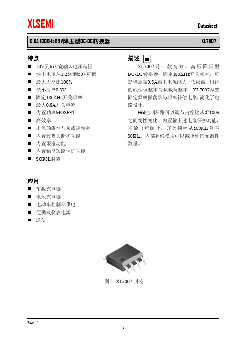
特点n 10V 到65V 宽输入电压范围 n 输出电压从1.25V 到50V 可调 n 最大占空比100% n 最小压降0.3V n 固定180KHz 开关频率 n 最大0.8A 开关电流 n 内置功率MOSFET n 高效率n 出色的线性与负载调整率 n 内置过热关断护功能 n 内置限流功能 n 内置输出短路保护功能 n SOP8L 封装应用n 车载充电器 n 电池充电器 n 电动车控制器供电 n 便携式仪表电源 n 通信描述XL7007是一款高效、高压降压型DC-DC 转换器,固定180KHz 开关频率,可提供最高0.8A 输出电流能力,低纹波,出色的线性调整率与负载调整率。
XL7007内置固定频率振荡器与频率补偿电路,简化了电路设计。
PWM 控制环路可以调节占空比从0~100%之间线性变化。
内置输出过电流保护功能,当输出短路时,开关频率从180KHz 降至36KHz 。
内部补偿模块可以减少外围元器件数量。
图1. XL7007封装0.8A 180KHz 65V降压型DC-DC转换器XL7007 引脚配置图2. XL7007引脚配置表1.引脚说明引脚号引脚名描述1 NC 无连接。
2 FB 反馈引脚,通过外部电阻分压网络,检测输出电压进行调整。
参考电压为1.25V。
3 VC 内部电压调节旁路电容,需要在VC与VIN之间并联1uF电容。
4 VIN 电源输入引脚,支持DC10V~65V范围电压输入,需要在VIN与GND之间并联电解电容以消除噪声。
5,6 SW 功率开关输出引脚,SW是输出功率的开关节点。
7,8 GND 接地引脚。
0.8A 180KHz 65V降压型DC-DC转换器XL7007 方框图图3. XL7007方框图典型应用图4. XL7007系统参数测量电路0.8A 180KHz 65V降压型DC-DC转换器XL7007 订购信息产品型号打印名称封装方式包装类型XL7007E1 XL7007E1 SOP-8L 2500只每卷XLSEMI无铅产品,产品型号带有“E1”后缀的符合RoHS标准。
XL4015 中文说明

IOUT(A) 0.1 0.2 0.4 0.6 0.8 1.0 1.2 1.4 1.6 1.8 2.0 2.2 2.4 2.6 2.8 3.0 3.2 3.4 3.6 3.8 4.0 4.2 4.4 4.6 4.8 5.0
EFF(%) 81.18 87.33 90.31 91.15 91.46 91.53 91.37 91.05 90.89 90.58 90.31 90.00 89.82 89.50 89.33 88.52 88.42 88.17 88.08 87.92 87.55 87.39 87.26 86.92 86.80 86.59
EFF(%) 71.78 80.03 85.80 87.94 88.58 88.63 88.48 88.74 88.68 88.54 88.53 88.61 88.77 88.51 87.91 86.94 86.91 86.65 86.64 86.65 86.54 86.50 86.49 86.49 86.41 86.74
第 4 页 ,共 6 页
第 1 页 ,共 6 页
XL4015 DEMO board manual
版 本:1.0 页 数:第 2 页, 共 6 页
物料清单
序号 1 2 3 4 5 6 7 8
数量 3 1 1 1 1 1 1 1
参考位号 C1,C2,CC
CIN COUT D1A L1 R1 R2 U1
说明 1uF,50V,Ceramic,X7R,0805 220uF,50V,Electrolytic,(10*16) 330uF,25V,Electrolytic,(10*12.5) 40V,5A,SMC,Schottky Barrier Rectifier
1.2
85.58
XL2012 规格书
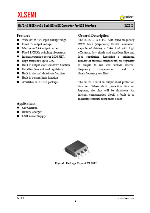
5V/2.4A 150KHz 40V Buck DC to DC Converter For USB Interface XL2012Featuresn Wide 8V to 40V input voltage range.n Fixed 5V output voltage.n Maximum 2.4A output current.n Fixed 150KHz switching frequency.n Internal optimize power MOSFET.n High efficiency up to 92%.n Built in output short shutdown function. n Excellent line and load regulation.n Built in thermal shutdown function.n Built in current limit function.n Available in SOIC-8 package. Applicationsn Car Charger.n Battery Charger.n USB Power Supply. General DescriptionThe XL2012 is a 150 KHz fixed frequency PWM buck (step-down) DC/DC converter, capable of driving a 2.4A load with high efficiency, low ripple and excellent line and load regulation. Requiring a minimum number of external components, the regulator is simple to use and include internal frequency compensation and a fixed-frequency oscillator.The XL2012 built in output short protection function. When short protection function happens, the chip will be shutdown.An internal compensation block is built in to minimize external component count.Figure1. Package Type of XL20125V/2.4A 150KHz 40V Buck DC to DC Converter For USB InterfaceXL2012Pin ConfigurationsFigure2. Pin Configuration of XL2012 (Top View)Table 1 Pin DescriptionPin Number Pin Name Description1 FB Feedback Pin (FB). The feedback threshold voltage is 5V.2 NC No Connected.3 VC Internal V oltage Regulator Bypass Capacity. In typical system application, The VC pin connect a 1uf capacity to VIN.4 VIN Supply V oltage Input Pin. XL2012 operates from 8V to 40V DC voltage. Bypass Vin to GND with a suitably large capacitor to eliminate noise on the input.5,6 SW Power Switch Output Pin (SW). SW is the switch node that supplies power to the output.7,8 GND Ground Pin. Care must be taken in layout. This pin should be placed outside of the schottky diode to output capacitor ground path to prevent switching current spikes from inducing voltage noise into XL2012.5V/2.4A 150KHz 40V Buck DC to DC Converter For USB Interface XL2012 Function BlockFigure3. Function Block Diagram of XL2012Typical Application CircuitFigure4. XL2012 Typical Application Circuit (VIN=8V~40V, VOUT=5V/2.4A)5V/2.4A 150KHz 40V Buck DC to DC Converter For USB Interface XL2012 Ordering InformationPart Number Marking ID Lead Free Lead Free Packing TypePackage TemperatureRangeXL2012E1 XL2012E1 2500 Units on Tape & ReelXLSEMI Pb-free products, as designated with “E1” suffix in the par number, are RoHS compliant.Absolute Maximum Ratings(Note1)Parameter Symbol Value Unit Input Voltage Vin -0.3 to 45 V Feedback Pin Voltage V FB-0.3 to Vin V Output Switch Pin Voltage V Output-0.3 to Vin V Power Dissipation P D Internally limited mW Thermal Resistance (SOP8L)(Junction to Ambient, No Heatsink, Free Air)R JA100 ºC/W Operating Junction Temperature T J-40 to 125 ºC Storage Temperature T STG-65 to 150 ºC Lead Temperature (Soldering, 10 sec) T LEAD260 ºC ESD (HBM) >2000 V Note1: Stresses greater than those listed under Maximum Ratings may cause permanent damage to the device. This is a stress rating only and functional operation of the device at these or any other conditions above those indicated in the operation is not implied. Exposure to absolute maximum rating conditions for extended periods may affect reliability.5V/2.4A 150KHz 40V Buck DC to DC Converter For USB Interface XL2012 XL2012 Electrical CharacteristicsT a = 25℃;unless otherwise specified.Symbol Parameter Test Condition Min. Typ. Max. Unit System parameters test circuit figure4VFB FeedbackV oltageVin = 8V to 40V, V out=5VIload=0.5A to 2.4A4.9 55.1 VEfficiency ŋVin=12V ,V out=5VIout=2.4A- 89 - %Electrical Characteristics (DC Parameters)Vin = 12V, GND=0V, Vin & GND parallel connect a 47uF/50V capacitor; Iout=500mA, T a = 25℃; the others floating unless otherwise specified.Parameters Symbol Test Condition Min. Typ. Max. Unit Input operation voltage Vin 8 40 V Quiescent Supply Current I q V FB =Vin 4.7 10 mA Output Short Supply Current Iosp 5 mA Oscillator Frequency Fosc 128 150 173 KHz Switch Current Limit I L V FB =0 2.6 AOutput Power PMOS Rdson V FB=0V, Vin=12V,I SW=2.4A60 80 mohm5V/2.4A 150KHz 40V Buck DC to DC Converter For USB InterfaceXL2012Typical System Application (VOUT=5V/2.4A)500100015002000250030000.00.51.01.52.02.53.03.54.04.55.05.5Output voltage VS Output currentO u t p u t v o l t a g e (V )Output current(mA)Figure6. XL2012 System Output Constant Current Curve5V/2.4A 150KHz 40V Buck DC to DC Converter For USB Interface XL2012404550556065707580859095100Efficiency VS Load currentE f f i c i e n c y (%)Load current(A)Figure7. XL2012 System Efficiency Curve5V/2.4A 150KHz 40V Buck DC to DC Converter For USB Interface XL2012Output short shutdown function descriptionThe output short shutdown function is built in XL2012. The short protection circuit monitors the output voltage, whenever FB pin voltage is below 1.5V, the short circuit protection circuit is triggered, the converter will be shutdown, input current less than 5mA.When the short fault is removed ,if output load is floating, then converter will restart up, the output voltage will return to normal; if output load isn ’t floating, then converter must be power reset , the output voltage will comeback.Figure8. The converter will be shutdown when output short happen.8101214161820222426283032343638401.01.11.21.31.41.51.61.71.81.92.0Input current VS Input voltageI n p u t c u r r e n t (m A )Input voltage(V)Figure9. The input current curve when output short happen.VOUTSwithing5V/2.4A 150KHz 40V Buck DC to DC Converter For USB Interface XL2012Package InformationSOP8 Package Mechanical Dimensions。
CD4012中文资料
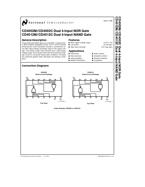
TL F 5940CD4002M CD4002C Dual 4-Input NOR Gate CD4012M CD4012C Dual 4-Input NAND GateMarch 1988CD4002M CD4002C Dual 4-Input NOR Gate CD4012M CD4012C Dual 4-Input NAND GateGeneral DescriptionThese NOR and NAND gates are monolithic complementa-ry MOS (CMOS)integrated circuits The N-and P-channel enhancement mode transistors provide a symmetrical cir-cuit with output swings essentially equal to the supply volt-age This results in high noise immunity over a wide supply voltage range No DC power other than that caused by leak-age current is consumed during static conditions All inputs are protected against static discharge and latching condi-tionsFeaturesY Wide supply voltage range 3 0V to 15V Y Low power10nW (typ )YHigh noise immunity0 45V DD (typ )ApplicationsY Automotive Y Alarm system Y Data terminals Y Industrial controls Y Instrumentation Y Remote metering YMedical ElectronicsYComputersConnection DiagramsCD4002Dual-In-Line PackageTL F 5940–1Top ViewCD4012Dual-In-Line PackageTL F 5940–2Top ViewOrder Number CD4002or CD4012C 1995National Semiconductor Corporation RRD-B30M105 Printed in U S AAbsolute Maximum Ratings(Note1)If Military Aerospace specified devices are required please contact the National Semiconductor Sales Office Distributors for availability and specifications Voltage at Any Pin V SS b0 3V to V DD a0 3V Operating Temperature RangeCD4002M CD4012M b55 C to a125 C CD4002C CD4012C b40 C to a85 C Storage Temperature Range(T S)b65 C to a150 C Power Dissipation(P D)Dual-In-Line700mW Small Outline500mW Operating Range(V DD)V SS a3 0V to V SS a15V Lead Temperature(T L)(Soldering 10seconds)260 CDC Electrical Characteristics CD4002M CD4012MLimitsSymbol Parameter Conditions b55 C a25 C a125 C UnitsMin Max Min Typ Max Min MaxI DD Quiescent V DD e5 0V0 050 0010 053 0m ADevice Current V DD e10V0 10 0010 16m A P D Quiescent Device V DD e5 0V0 250 0050 2515m W Dissipation Package V DD e10V1 00 011 060m W V OL Output Voltage V DD e5 0V V I e V DD I O e0A0 0500 050 05V Low Level V DD e10V V I e V DD I O e0A0 0500 050 05V V OH Output Voltage V DD e5 0V V I e V SS I O e0A4 954 955 04 95V High Level V DD e10V V I e V SS I O e0A9 959 95109 95V V NL Noise Immunity V DD e5 0V V O e3 6V I O e0A1 51 52 251 4V (All Inputs)V DD e10V V O e7 2V I O e0A3 03 04 52 9V V NH Noise Immunity V DD e5 0V V O e0 95V I O e0A1 41 52 251 5V (All Inputs)V DD e10V V O e2 9V I O e0A2 93 04 53 0V I D N Output Drive Current V DD e5 0V V O e0 4V V I e V DD0 50 401 00 28mAN-Channel(4002)V DD e10V V O e0 5V V I e V DD1 10 92 50 65mA (Note2)I D P Output Drive Current V DD e5 0V V O e2 5V V I e V SS b0 62b0 5b2 0b0 35mAP-Channel(4002)V DD e10V V O e9 5V V I e V SS b0 62b0 5b1 0b0 35mA (Note2)I D N Output Drive Current V DD e5 0V V O e0 4V V I e V DD0 310 250 50 175mAN-Channel(4012)V DD e10V V O e0 5V V I e V DD0 630 50 60 35mA (Note2)I D P Output Drive Current V DD e5 0V V O e2 5V V I e V SS b0 31b0 25b0 5b0 175mAP-Channel(4012)V DD e10V V O e9 5V V I e V SS b0 75b0 6b1 2b0 4mA (Note2)I I Input Current10pANote1 ‘‘Absolute Maximum Ratings’’are those values beyond which the safety of the device cannot be guaranteed Except for‘‘Operating Temperature Range’’they are not meant to imply that the devices should be operated at these limits The table of‘‘Electrical Characteristics’’provides conditions for actual device operationNote2 I D N and I D P are tested one output at a time2DC Electrical Characteristics CD4002C CD4012CLimitsSymbol Parameter Conditions b55 C a25 C a85 C UnitsMin Max Min Typ Max Min MaxI DD Quiescent V DD e5 0V0 50 0050 515m ADevice Current V DD e10V5 00 0055 030m A P D Quiescent Device V DD e5 0V2 50 0252 575m W Dissipation Package V DD e10V500 0550300m W V OL Output Voltage V DD e5 0V V I e V DD I O e0A0 0500 050 05V Low Level V DD e10V V I e V DD I O e0A0 0500 050 05V V OH Output Voltage V DD e5 0V V I e V SS I O e0A4 954 955 04 95V High Level V DD e10V V I e V SS I O e0A9 959 95109 95V V NL Noise Immunity V DD e5 0V V O t3 6V I O e0A1 51 52 251 4V (All Inputs)V DD e10V V O t7 2V I O e0A3 03 04 52 9V V NH Noise Immunity V DD e5 0V V O s0 95V I O e0A1 41 52 251 5V (All Inputs)V DD e10V V O s2 9V I O e0A2 93 04 53 0V I D N Output Drive Current V DD e5 0V V O e0 4V V I e V DD0 350 31 00 24mAN-Channel(4002)V DD e10V V O e0 5V V I e V DD0 720 62 50 48mA (Note2)I D N Output Drive Current V DD e5 0V V O e0 4V V I e V DD0 1450 120 50 095mAN-Channel(4012)V DD e10V V O e0 5V V I e V DD0 30 250 60 2mA (Note2)I D P Output Drive Current V DD e5 0V V O e2 5V V I e V SS b0 35b0 3b2 0b0 24mAP-Channel(4002)V DD e10V V O e9 5V V I e V SS b0 3b0 25b1 0b0 2mA (Note2)I D P Output Drive Current V DD e5 0V V O e2 5V V I e V SS b0 145b0 12b0 5b0 095mAP-Channel(4012)V DD e10V V O e9 5V V I e V SS b0 35b0 3b1 2b0 24mA (Note2)I I Input Current10pANote1 ‘‘Absolute Maximum Ratings’’are those values beyond which the safety of the device cannot be guaranteed Except for‘‘Operating Temperature Range’’they are not meant to imply that the devices should be operated at these limits The table of‘‘Electrical Characteristics’’provides conditions for actual device operationNote2 I D N and I D P are tested one output at a time3AC Electrical Characteristics T A e25 C C L e15pF and input rise and fall times e20ns Typical temperature coefficient for all values of V DD e0 3% CSymbol Parameter Conditions Min Typ Max Units CD4002Mt PHL Propagation Delay Time V DD e5 0V3550ns High to Low Level V DD e10V2540ns t PLH Propagation Delay Time V DD e5 0V3550ns Low to High Level V DD e10V2540ns t THL Transition Time High V DD e5 0V65175ns to Low Level V DD e10V3575ns t TLH Transition Time Low V DD e5 0V65125ns to High Level V DD e10V3570nsC IN Input Capacitance Any Input5 0pFCD4002Ct PHL Propagation Delay Time V DD e5 0V35120ns High to Low Level V DD e10V2565ns T PLH Propagation Delay Time V DD e5 0V3580ns Low to High Level V DD e10V2555ns t THL Transition Time High V DD e5 0V65300ns to Low Level V DD e10V35125ns t TLH Transition Time Low V DD e5 0V65200ns to High Level V DD e10V35115nsC IN Input Capacitance Any Input5 0pFAC Parameters are guaranteed by DC correlated testingAC Electrical Characteristics T A e25 C C L e15pF and input rise and fall times e20ns Typical temperature coefficient for all values of V DD e0 3% CSymbol Parameter Conditions Min Typ Max Units CD4012Mt PHL Propagation Delay Time V DD e5 0V5075ns High to Low Level V DD e10V2540ns t PLH Propagation Delay Time V DD e5 0V5075ns Low to High Level V DD e10V2540ns t THL Transition Time High V DD e5 0V75125ns to Low Level V DD e10V5075ns t TLH Transition Time Low V DD e5 0V75100ns to High Level V DD e10V4060nsC IN Input Capacitance Any Input5 0pFCD4012Ct PHL Propagation Delay Time V DD e5 0V50100ns High to Low Level V DD e10V2550ns T PLH Propagation Delay Time V DD e5 0V50100ns Low to High Level V DD e10V2550ns t THL Transition Time High V DD e5 0V75150ns to Low Level V DD e10V50100ns t TLH Transition Time Low V DD e5 0V75125ns to High Level V DD e10V4075nsC IN Input Capacitance Any Input5 0pFAC Parameters are guaranteed by DC correlated testingNote1 ‘‘Absolute Maximum Ratings’’are those values beyond which the safety of the device cannot be guaranteed Except for‘‘Operating Temperature Range’’they are not meant to imply that the devices should be operated at these limits The table of‘‘Electrical Characteristics’’provides conditions for actual device operation4Physical Dimensions inches(millimeters)Ceramic Dual-In-Line Package(J)Order Number CD4002MJ CD4002CJ CD4012MJ or CD4012CJNS Package Number J14A5C D 4002M C D 4002C D u a l 4-I n p u t N O R G a t e C D 4012M C D 4012C D u a l 4-I n p u t N A N D G a t ePhysical Dimensions inches (millimeters)(Continued)Molded Dual-In-Line Package (N)Order Number CD4002MN CD4002CN CD4012MN or CD4012CNNS Package Number N14ALIFE SUPPORT POLICYNATIONAL’S PRODUCTS ARE NOT AUTHORIZED FOR USE AS CRITICAL COMPONENTS IN LIFE SUPPORT DEVICES OR SYSTEMS WITHOUT THE EXPRESS WRITTEN APPROVAL OF THE PRESIDENT OF NATIONAL SEMICONDUCTOR CORPORATION As used herein 1 Life support devices or systems are devices or 2 A critical component is any component of a life systems which (a)are intended for surgical implant support device or system whose failure to perform can into the body or (b)support or sustain life and whose be reasonably expected to cause the failure of the life failure to perform when properly used in accordance support device or system or to affect its safety or with instructions for use provided in the labeling can effectivenessbe reasonably expected to result in a significant injury to the userNational Semiconductor National Semiconductor National Semiconductor National Semiconductor CorporationEuropeHong Kong LtdJapan Ltd1111West Bardin RoadFax (a 49)0-180-530858613th Floor Straight Block Tel 81-043-299-2309。
XL4016原厂规格书(2014版)

8A 180KHz 40V Buck DC to DC Converter XL4016Featuresn Wide 8V to 40V Input Voltage Range n Output Adjustable from 1.25V to 36V n Maximum Duty Cycle 100%n Minimum Drop Out 0.3Vn Fixed 180KHz Switching Frequencyn8A Constant Output Current Capability n Internal Optimize Power MOSFETn High efficiency up to 96%n Excellent line and load regulationn Built in thermal shutdown functionn Built in current limit functionn Built in output short protection function n Built in input over voltage protection n Available in TO220-5L package Applicationsn LCD Monitor and LCD TVn Portable instrument power supplyn Telecom / Networking Equipment General DescriptionThe XL4016 is a 180 KHz fixed frequency PWM buck (step-down) DC/DC converter, capable of driving a 8A load with high efficiency, low ripple and excellent line and load regulation. Requiring a minimum number of external components, the regulator is simple to use and include internal frequency compensation and a fixed-frequency oscillator.The PWM control circuit is able to adjust the duty ratio linearly from 0 to 100%. An over current protection function is built inside. When short protection function happens, the operation frequency will be reduced from 180KHz to 48KHz. An internal compensation block is built in to minimize external component count.Figure1. Package Type of XL40168A 180KHz 40V Buck DC to DC ConverterXL4016Pin ConfigurationsFigure2. Pin Configuration of XL4016 (Top View) Table 1 Pin DescriptionPin Number Pin Name Description1 GND Ground Pin. Care must be taken in layout. This pin should be placed outside of the Schottky Diode to output capacitor ground path to prevent switching current spikes from inducing voltage noise into XL4016.2 FB Feedback Pin (FB). Through an external resistor divider network, FB senses the output voltage and regulates it. The feedback threshold voltage is 1.25V.3 SW Power Switch Output Pin (SW). SW is the switch node that supplies power to the output.4 VC Internal V oltage Regulator Bypass Capacity. In typical system application, The VC pin connect a 1uf capacity to VIN.5 VIN Supply V oltage Input Pin. XL4016 operates from a 8V to 40V DC voltage. Bypass Vin to GND with a suitably large capacitor to eliminate noise on the input.8A 180KHz 40V Buck DC to DC Converter XL4016 Function BlockFigure3. Function Block Diagram of XL4016Typical Application CircuitFigure4. XL4016 Typical Application Circuit (VIN=8V~40V, VOUT=5V/8A)8A 180KHz 40V Buck DC to DC Converter XL4016 Ordering InformationPart Number Marking ID Lead Free Lead Free Packing TypePackage TemperatureRangeXL4016E1 XL4016E1 TubeXLSEMI Pb-free products, as designated with “E1” suffix in the par number, are RoHS compliant.Absolute Maximum Ratings(Note1)Parameter Symbol Value Unit Input Voltage Vin -0.3 to 45 V Feedback Pin Voltage V FB-0.3 to Vin V Output Switch Pin Voltage V Output-0.3 to Vin V Power Dissipation P D Internally limited mW Thermal Resistance (TO220-5L)(Junction to Ambient, No Heatsink, Free Air)R JA30 ºC/W Operating Junction Temperature T J-40 to 125 ºC Storage Temperature T STG-65 to 150 ºC Lead Temperature (Soldering, 10 sec) T LEAD260 ºC ESD (HBM) >2000 V Note1: Stresses greater than those listed under Maximum Ratings may cause permanent damage to the device. This is a stress rating only and functional operation of the device at these or any other conditions above those indicated in the operation is not implied. Exposure to absolute maximum rating conditions for extended periods may affect reliability.8A 180KHz 40V Buck DC to DC Converter XL4016 XL4016 Electrical CharacteristicsT a = 25℃;unless otherwise specified.Symbol Parameter Test Condition Min. Typ. Max. Unit System parameters test circuit figure4VFB FeedbackV oltageVin = 8V to 40V, V out=5VIload=0.5A to 8A1.225 1.25 1.275 VEfficiency ŋVin=12V ,V out=5VIout=6A- 87 - %Efficiency ŋVin=24V ,V out=12VIout=6A- 93 - %Electrical Characteristics (DC Parameters)Vin = 12V, GND=0V, Vin & GND parallel connect a 470uf/50V capacitor; Iout=500mA, T a = 25℃; the others floating unless otherwise specified.Parameters Symbol Test Condition Min. Typ. Max. Unit Input operation voltage Vin 8 40 V Quiescent Supply Current I q V FB =Vin 2.1 5 mA Oscillator Frequency Fosc 144 180 216 KHz Output Short Frequency Fosp 48 KHz Switch Current Limit I L V FB =0 10 A Max. Duty Cycle D MAX V FB=0V 100 %Output Power PMOS Rdson V FB=0V, Vin=12V,I SW=8A40 50 mohmVin Over V oltage Protection OVP 45 V8A 180KHz 40V Buck DC to DC ConverterXL4016Typical System Application (VOUT=5V/8A)Figure5. XL4016 System Parameters Test Circuit (VIN=8V~40V, VOUT=5V/8A)50556065707580859095100Efficiency VS Load currentE f f i c i e n c y (%)Load current(A)Figure6. XL4016 System Efficiency Curve8A 180KHz 40V Buck DC to DC ConverterXL4016Typical System Application (VOUT=12V/6A)Figure7. XL4016 System Parameters Test Circuit (VIN=15V~40V, VOUT=12V/6A)0.00.51.01.52.02.53.03.54.04.55.05.56.050556065707580859095100Efficiency VS Load currentE f f i c i e n c y (%)Load current(A)Figure8. XL4016 System Efficiency Curve8A 180KHz 40V Buck DC to DC Converter XL4016Typical System Application (With Enable function)Logic level signal shutdown function can be used in typical system application with external components. When the TTL high voltage above 3.3V(referenced to ground, lower than VIN), the converter will shutdown, input current less than 3mA;when the TTL Low voltage below 0.8V(referenced to ground), the converter will turn on.L1 47uH/12AFigure9. XL4016 Typical Application Circuit with Enable Function8A 180KHz 40V Buck DC to DC Converter XL4016Package InformationTO220-5L。
VIS Infinera 12x1 4x1 VCSEL芯片数据表说明书

No. 120314-Rev 1.0March 2012Product CParameter Typical NotesEmission Wavelength 850 nmavailable from 835 – 860 nm Data RateUp 28 Gbit/s per channel Rise time (20% to 80%) < 15 ps Threshold Current 1.0 mA Peak Output Power7 mWProduct Description Product DescriptionThese compact and very high modulation rate top-emitting GaAs-based vertical cavity surface emitting laser (VCSEL) chips and 1xN (N=1, 2, 4, 12, etc.) arrays are available as engineering samples for use in the development and evaluation of opticalinterconnections, optical backplanes and integrated waveguides, and next-generation optical data communications systems. The VCSELs are contacted on the top-surface individually using ground-source (GS) microprobes, wire bonds, or flip-chip bonds.DatasheetFeatures· available in 4x1 and 12x1configuration · up to 28 Gbit/s per channel · high temperature stability · standard pitch size 250 µm · high device-to-device uniformity Applications· 40/100 Gbit/s Ethernet · Infiniband FDR · OTU4 100 Gbit/s· Proprietary optical interconnects · Active Optical Cables (AOC)VI Systems GmbH Hardenbergstrasse 7 D-10623 Berlin28 Gbit/s VCSELs and VCSEL Arrays (850 nm)Product Code:V25B-850C 1x1 V25B -850C4 4x1 arrayV25B -850C12 12x1 arrayPreliminarySample image only. Actual product may vary.DatasheetV25B-850CPreliminary Electro Optical SpecificationsAbsolute Maximum RatingsAll product specifications and descriptions are subject to change without notice. VI Systems GmbH Hardenbergstrasse 7 D-10623 Berlin No. 120314-Rev 1.0 March 2012No. 120314-Rev 1.0March 2012DatasheetV15-850CPreliminaryVI Systems GmbH Hardenbergstrasse 7 D-10623 BerlinNo. 120314-Rev 1.0March 2012All product specifications and descriptions are subject to change without notice.Pleasecontactoursalesdepartmentforadditionalinformationandtoreceiveaquotation:*********************VI Systems GmbH Hardenbergstrasse 7 D-10623 BerlinThe V25B-850C has been tested to meet specifications outlined in this data sheet at room temperature. However, it has not undergone full qualification testing or characterization and therefore may not meet the performance specifications over all extremes.Limited Qualification NotificationVI Systems GmbH Hardenbergstrasse 7 10623 BerlinTel.: +49 30 3083143 30 Fax: +49 30 3083143 59 *********************DatasheetV25B-850C。
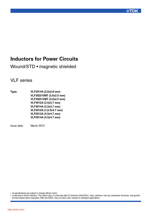
VLF4012AT-4R7M1R1;VLF4012AT-100MR79;VLF4012AT-3R3M1R3;VLF4012AT-2R2M1R5;中文规格书,Datasheet资料
Inductance tolerance(%) ±30 ±20 ±20 ±20 ±20 ±20 ±20
Test frequency (kHz) 100 100 100 100 100 100 100
DC resistance( ) max. 0.054 0.1 0.15 0.2 0.31 0.46 1.20 typ. 0.047 0.091 0.13 0.1R7
2.8±0.2
1.4max. Dimensions in mm
RECOMMENDED PC BOARD PATTERN
1.2 2.1 3.4 Dimensions in mm
Inductance [at 1/2 Idc1]3 (µH) 1 2.2 3.3 4.7 6.8 10 22
• All specifications are subject to change without notice.
/
001-04 / 20120310 / e531_vlf
(3/17)
Inductors for Power Circuits Wound/STD • Magnetic Shielded
Part No. VLF3014AT-1R0N1R7 VLF3014AT-2R2M1R2 VLF3014AT-3R3M1R0 VLF3014AT-4R7MR90 VLF3014AT-6R8MR72 VLF3014AT-100MR59 VLF3014AT-220MR37
1
SHAPES AND DIMENSIONS
VLF-MT Series VLF302510MT
With the VLF302510MT Series, a DC to DC converter with topclass voltage conversion efficiency for similar size products was achieved by optimizing the magnetic material and configuration. These products are optimal for use as choke coils in switching power supplies such as those in mobile devices requiring spacesaving design. FEATURES • Miniature size Mount area: 3.02.5mm Low profile: 1.0mm max. height • Generic use for portable DC to DC converter line. • High magnetic shield construction should actualize high resolution for EMC protection. • The products contain no lead and also support lead-free soldering. • The products is halogen-free. • It is a product conforming to RoHS directive. APPLICATIONS Smartphones, cellular phones, DSCs, DVCs, HDDs, LCD displays, compact power supply modules, etc. SHAPES AND DIMENSIONS
DATASHEET (TP4054 线性锂离子电池充电器)

间,并应通过至少一个 1μF 电容器进行旁 路。当 VCC 降至 BAT 引脚电压的 30mV 以 内,TP4054 进入停机模式,从而使 IBAT 降至 2μA 以下。 PROG(引脚 5) :充电电流设定、充电电流 监控和停机引脚。 在该引脚与地之间连接一 个精度为 1%的电阻器 RPROG 可以设定充电 电流。当在恒定电流模式下进行充电时,引 脚的电压被维持在 1V。 PROG 引脚还可用来关断充电器。将设定电 阻器与地断接,内部一个 2.5μA 电流将 PROG 引脚拉至高电平。当该引脚的电压达 到 2.70V 的停机门限电压时, 充电器进入停 机模式,充电停止且输入电源电流降至 45μA。重新将 RPROG 与地相连将使充电器 恢复正常操作状态。
TEL:0755-82863877 13242913995 FAX:0755-82863778 E-MAIL:panxia168@
DATASHEET
(TP4054 线性锂离子电池充电器)
1
TP4054 线性锂离子电池充电器
描述
TP4054 是一款完整的单节锂离子电池采用恒定电流/恒定电压线性充电器。其 SOT 封装与较少的外部元件数目使得 TP4054 成为便携式应用的理想选择。 TP4054 可以适合 USB 电源和适配器电源工作。 由于采用了内部 PMOSFET 架构,加上防倒充电路,所以不需要外部检测电阻器和 隔离二极管。热反馈可对充电电流进行调节,以便在大功率操作或高环境温度条件下对 芯片温度加以限制。 充电电压固定于 4.2V, 而充电电流可通过一个电阻器进行外部设置。 当充电电流在达到最终浮充电压之后降至设定值 1/10 时, TP4054 将自动终止充电循环。 当输入电压(交流适配器或 USB 电源)被拿掉时,TP4054 自动进入一个低电流状 态,将电池漏电流降至 2uA 以下。也可将 TP4054 置于停机模式,以而将供电电流降至 45uA。TP4054 的其他特点包括充电电流监控器、欠压闭锁、自动再充电和一个用于指 示充电结束和输入电压接入的状态引脚。
xl4015中文资料_数据手册_参数

Pin Number 1
2 3 4 5
Pin Name GND
FB SW VC VIN
Description
Ground Pin. Care must be taken in layout. This pin should be placed outside of the Schottky Diode to output capacitor ground path to prevent switching current spikes from inducing voltage noise into XL4015. Feedback Pin (FB). Through an external resistor divider network, FB senses the output voltage and regulates it. The feedback threshold voltage is 1.25V. Power Switch Output Pin (SW). SW is the switch node that supplies power to the output. Internal Voltage Regulator Bypass Capacity. In typical system application, The VC pin connect a 1uf capacity to VIN. Supply Voltage Input Pin. XL4015 operates from a 8V to 36V DC voltage. Bypass Vin to GND with a suitably large capacitor to eliminate noise on the input.
XL4012 demo board manual
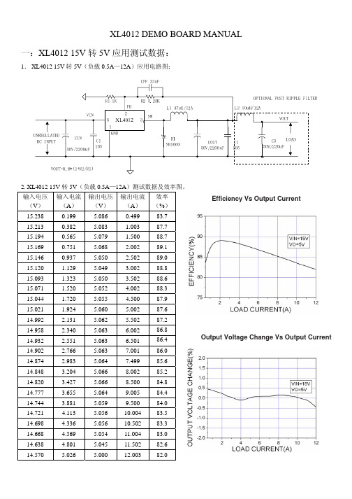
9.005
84.4
14.744
3.881
5.059
9.500
84.0
14.721
4.113
5.056
10.004
83.5
14.698
4.336
5.056
10.502
83.3
14.668
4.569
5.054
11.004
83.0
14.638
4.801
5.045
11.502
82.6
14.570
5.026
5.000
5.058
8.504 82.4
24.19
2.292
5.059
9.000 82.1
24.17
2.431
5.055
9.501 81.7
24.15
2.576
5.067 10.008 81.5
24.13
2.714
5.064 10.500 81.2
24.11
2.856
5.059 11.001 80.8
24.09
6.002
86.8
14.932
2.551
5.063
6.501
86.4
14.902
2.766
5.063
7.001
86.0
14.874
2.983
5.064
7.499
85.6
14.848
3.204
5.066
8.002
85.2
14.820
3.427
5.066
8.500
84.8
14.777
3.655
5.064
输出电容(50V/2200uF) 24℃ 25℃ 28℃ 30℃ 32℃ 33℃ 35℃
英飞凌汽车电子器件选型

Lowbeam Indicator Park Optional Fog
55W
27W 10W 2x 55W
Park Indicator Lowbeam Highbeam
10W 27W 55W
65W
Highbeam 65W
Lowbeam 55W
Indicator 27W
Left Front-Light
Control
Right Front-Light
Control
LEDs
Relays
m n
Low-Side Driver
HITFET ™ BTS3110/18
BTS3134 BTS3160D
Interior Light
LED Driver
Basic LED Driver without Status
BCR40x
Basic LED Driver TLE424x
Power System ICs
C Smart Power C System Integration
– ABS/Airbag – Powertrain – Body
Infineon® Embedded Power ICs
C Single Package C Smart Power and
Controller Integration
System Basis Chip TLE826xE TLE826x-2E
Optional: DC/DC Regulator
TLF50281
Single or Dual High-Side Driver
Supply
Communication
32-bit Multicore/Lockstep
EG4002_datasheet
ELECTRONIC GIANT EG4002芯片数据手册红外热释电专用芯片红外热释电专用芯片版本变更记录红外热释电专用芯片目录1. 特点 (4)2. 描述 (4)3. 应用领域 (4)4. 引脚 (5)4.1. 引脚定义 (5)4.2. 引脚描述 (5)5. 结构框图 (6)6. 典型应用电路 (6)6.1 EG4002典型应用电路图 (6)6.2 EG4002控制继电器应用电路图 (7)6.3 EG4002可重复触发+光敏电阻应用电路图 (7)7. 电气特性 (8)7.1 极限参数 (8)7.2 典型参数 (9)8. 应用设计 (10)8.1振荡器工作频率计算 (10)8.2触发延时时间定时器和触发封锁时间定时器 (10)8.3A端重复和不可重复触发功能 (11)8.4Vc触发禁止端 (12)8.5第一级运放增益设定 (12)9. 封装尺寸 (13)9.1 DIP8封装尺寸 (13)9.2 SOP8封装尺寸 (13)红外热释电专用芯片EG4002芯片数据手册V1.21. 特点⏹8引脚数红外热释电专用芯片,外围电路简单,成本低⏹静态功耗小,3V工作电源时功耗小于45uA, 5V工作电源时功耗小于75uA,非常适合电池供电系统应用⏹高输入阻抗运算放大器,可与多种传感器匹配,进行信号与处理⏹双向鉴幅器,可有效抑制干扰⏹内置参考电压,供内部比较器和运放的参考电压⏹内设延时时间定时器和封锁时间定时器,改变振荡器频率即可设定定时延时时间⏹外围元器件少,只需配置第一级运放的增益和振荡器的RC器件即能可靠工作⏹工作电源+3V~+6V⏹封装形式: SOP8和DIP82. 描述EG4002是一款专为热释电红外传感器信号放大及处理输出的数模混合专用芯片,内部集成了运算放大器、双门限电压比较器、参考电压源、延时时间定时器和封锁时间定时器及状态控制器等,专用于防盗报警系统、人体门控制装置、照明控制开关等场合。
EG4002电源工作电压为+3V~+6V,采用 COMS工艺数模混合相结合的集成电路,8个引脚数封装设计,降低了外围电路元件数和整体成本,节省了PCB板空间。
180KHz 40V 12A开关电流降压型DC-DC转换器说明书
180KHz 40V 12A 开关电流降压型DC-DC转换器XL4016特点⏹推荐操作电压范围8V~36V ⏹输出电压从1.25V到32V可调⏹最大占空比100%⏹最小压降0.3V⏹固定180KHz开关频率⏹最大12A开关电流⏹内置功率MOS⏹效率高达96%⏹出色的线性与负载调整率⏹内置热关断功能⏹内置限流功能⏹内置输出短路保护功能⏹TO220-5L封装应用⏹LCD电视与显示屏⏹便携式仪器电源⏹通讯设备供电描述XL4016是一款高效降压型DC-DC转换器,固定180KHz开关频率, 可以提供最高12A输出电流能力,具有低纹波,出色的线性与负载调整率特点。
XL4016内置固定频率振荡器与频率补偿电路,简化了电路设计。
PWM控制环路可以调节占空比从0~100%之间线性变化。
内置输出过电流保护功能。
当输出短路时,开关频率从180KHz降至48KHz。
内置补偿模块可以减少外围元器件数量。
图1.XL4016封装180KHz 40V 12A 开关电流降压型DC-DC 转换器 XL4016引脚配置12345VIN SW FB GNDVC TO220-5LMetal Tab SW图2. XL4016引脚配置表1.引脚说明引脚号 引脚名称 描述1 GND 接地引脚。
2 FB 反馈引脚,通过外部电阻分压网络,检测输出电压进行调整,参考电压为1.25V 。
3 SW 功率开关输出引脚,SW 是输出功率的开关节点。
4VC内部电压调节器旁路电容引脚,需要在VIN 与VC 引脚之间连接1个1uF 电容。
5 VIN电源输入引脚,支持DC8V~36V 宽范围电压操作,需要在VIN 与GND 之间并联电解电容以消除噪声。
180KHz 40V 12A 开关电流降压型DC-DC 转换器 XL4016方框图EAGND FB3.3V1.25VEA COMPOscillator180KHz/48KHz3.3V Regulator1.25V ReferenceStart Up LatchCOMP2COMP1DriverThermal ShutdownVINVC SW220mV 200mV20m ΩCurrent LimitPower PMOS1:100020K Ω3.3nFOSP图3. XL4016方框图典型应用XL4016CIN470uF/50VCOUT1000uF/25VR210K R13.3KD1MBR2045C1105C21055312VIN4VOUT=1.25*(1+R2/R1)IOUT=0~12AVIN VCSWGNDFBCC 105CFF 33nFVOUTVIN=8V~20V, VOUT=5V/9A; VIN=20V~36V, VOUT=5V/12A 图4. XL4016系统参数测量电路(VIN=8~36V, VOUT=5V/12A )180KHz 40V 12A开关电流降压型DC-DC转换器XL4016订购信息产品型号打印名称封装方式包装类型XL4016E1 XL4016E1 TO220-5L 50只每管/ 1000只每盒XLSEMI无铅产品,产品型号带有“E1”后缀的符合RoHS标准。
XL60XX,XL40XX,XLxxxx系列恒流恒压驱动IC归类参数
恒流设置
封装形式
XL8001
12V ~ 80V
1~8 LED串联
0.5A
PFM
Adj (0.1V)
SOP8L
XL8002
12V ~ 80V
1~18 LED串联
1A
PFM
Adj (0.1V)
TO263-5L
XL8003
24V ~ 80V
3~8 LED串联
0.5A
PFM
Adj (0.2V)
SOP8L
降压型直流电源变换器芯片(常规型)
产品型号
输入电压
最大输出电流
开关频率
电压版本
封装类型
XL1507
4.5V ~ 40V
3A
150KHz
Adj (1.23V)/3.3V/5V/12V
TO252-5L
XL1509
4.5V ~ 40V
2A
150KHz
Adj (1.23V)/3.3V/5V/12V
SOP8L
5V ~ 32V
5A
300KHz
Adj (0.8V)
TO263-5L
XL4012
5V ~ 32V
12A
300KHz
Adj (0.8V)
TO220-5L
升压型直流电源变换器芯片
产品型号
输入电压
最大输出电压
最大开关电流
开关频率
电压版本
封装形式
XL6007
3.6V ~ 24V
60V
2A
400KHz
Adj (1.25V)
2 ~ 8串
0.5A
PFM
0.2V
SOP8L
XL5004
80V ~ 400V
XL4012
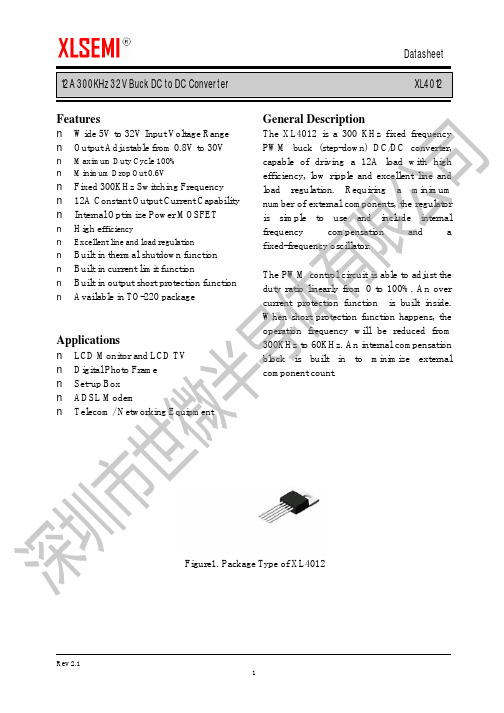
12A 300KHz 32V Buck DC to DC Converter XL4012Featuresn Wide 5V to 32V Input Voltage Range n Output Adjustable from 0.8V to 30Vn Maximum Duty Cycle 100% n Minimum Drop Out 0.6Vn Fixed 300KHz Switching Frequency n 12A Constant Output Current Capability n Internal Optimize Power MOSFET n High e fficiencyn Excellent line and load regulation n Built in thermal shutdown function n Built in current limit functionn Built in output short protection function n Available in TO-220 packageApplicationsn LCD Monitor and LCD TV n Digital Photo Frame n Set-up Box n ADSL ModemnTelecom / Networking EquipmentGeneral DescriptionThe XL4012 is a 300 KHz fixed frequency PWM buck (step-down) DC/DC converter, capable of driving a 12A load with high efficiency, low ripple and excellent line and load regulation. Requiring a minimum number of external components, the regulator is simple to use and include internal frequency compensation and a fixed-frequency oscillator.The PWM control circuit is able to adjust the duty ratio linearly from 0 to 100%. An over current protection function is built inside. When short protection function happens, the operation frequency will be reduced from 300KHz to 60KHz. An internal compensation block is built in to minimize external component count.Figure1. Package Type of XL401212A 300KHz 32V Buck DC to DC ConverterXL4012Pin ConfigurationsFigure2. Pin Configuration of XL4012 (Top View) Table 1 Pin DescriptionPin Number Pin Name Description1 GND Ground Pin. Care must be taken in layout. This pin should be placed outside of the Schottky Diode to output capacitor ground path to prevent switching current spikes from inducing voltage noise into XL4012.2 FB Feedback Pin (FB). Through an external resistor divider network, FB senses the output voltage and regulates it. The feedback threshold voltage is 0.8V.3 SW Power Switch Output Pin (SW). SW is the switch node that supplies power to the output.4, 5 VIN Supply V oltage Input Pin. XL4012 operates from a 5V to 32V DC voltage. Bypass Vin to GND with a suitably large capacitor to eliminate noise on the input.12A 300KHz 32V Buck DC to DC Converter XL4012Figure4. XL4012 Typical Application Circuit 24V~12V/10A12A 300KHz 32V Buck DC to DC Converter XL4012 Ordering InformationPart Number Marking ID Lead Free Lead Free Packing TypePackage TemperatureRangeXL4012E1 XL4012E1 TubeXLSEMI Pb-free products, as designated with “E1” suffix in the par number, are RoHS compliant.Absolute Maximum Ratings(Note1)Parameter Symbol Value Unit Input Voltage Vin -0.3 to 35 V Feedback Pin Voltage V FB-0.3 to Vin V Output Switch Pin Voltage V Output-0.3 to Vin V Power Dissipation P D Internally limited mW Thermal Resistance (TO220)(Junction to Ambient, No Heatsink, Free Air)R JA30 ºC/W Operating Junction Temperature T J-40 to 125 ºC Storage Temperature T STG-65 to 150 ºC Lead Temperature (Soldering, 10 sec) T LEAD260 ºC ESD (HBM) 2000 V Note1: Stresses greater than those listed under Maximum Ratings may cause permanent damage to the device. This is a stress rating only and functional operation of the device at these or any other conditions above those indicated in the operation is not implied. Exposure to absolute maximum rating conditions for extended periods may affect reliability.12A 300KHz 32V Buck DC to DC Converter XL4012 XL4012 Electrical CharacteristicsT a = 25℃;unless otherwise specified.Symbol Parameter Test Condition Min. Typ. Max. Unit System parameters test circuit figure4VFB FeedbackV oltageVin = 7V to 32V, V out=5VIload=0.5A to 12A0.776 0.8 0.824 VEfficiency ŋVin=15V ,V out=5VIout=12A- 93 - %Electrical Characteristics (DC Parameters)Vin = 12V, GND=0V, Vin & GND parallel connect a 220uf/50V capacitor; Iout=500mA, T a = 25℃; the others floating unless otherwise specified.Parameters Symbol Test Condition Min. Typ. Max. Unit Input operation voltage Vin 5 32 V Quiescent Supply Current I q V FB =Vin 3 5 mA Oscillator Frequency Fosc 240 300 360 Khz Switch Current Limit I L V FB =0 14 A Max. Duty Cycle D MAX V FB=0V 100 %12A 300KHz 32V Buck DC to DC Converter XL401212A 300KHz 32V Buck DC to DC Converter XL4012 Schottky Diode Selection TableCurrent SurfaceMount ThroughHoleVR (The same as system maximum input voltage)20V 30V 40V 50V 60V1A √1N5817 1N5818 1N5819√1N5820 1N5821 1N5822√MBR320 MBR330 MBR340 MBR350 MBR360 √SK32 SK33 SK34 SK35 SK36√30WQ03 30WQ04 30WQ05√31DQ03 31DQ04 31DQ053A√SR302 SR303 SR304 SR305 SR306√1N5823 1N5824 1N5825√SR502 SR503 SR504 SR505 SR506√SB520 SB530 SB540 SB550 SB560 5A√50WQ03 50WQ04 50WQ058A √SR820 SR830 SR840 SR850 SR860 16A √SR1620 SR1630 SR1640 SR1650 SR166012A 300KHz 32V Buck DC to DC Converter XL401212A 300KHz 32V Buck DC to DC Converter XL4012Package InformationTO220-5L。
振源胶囊治疗冠心病心绞痛有效性的Meta分析
振源胶囊治疗冠心病心绞痛有效性的Meta分析刘 宁摘要:目的 通过Meta 分析评价振源胶囊治疗冠心病心绞痛的有效性㊂方法 检索Cochrane 图书馆㊁PubMed 数据库㊁中国期刊全文数据库㊁中文科技期刊全文数据库等文献数据库,全面收集冠心病心绞痛应用振源胶囊与标准治疗冠心病心绞痛的随机对照试验,按照Cochrane Library Handbook 推荐的质量评价方法评价纳入研究的质量,并对符合纳入标准的研究用RevMan5.3软件对数据进行Meta 分析㊂结果 纳入6篇随机对照试验,共682例病人,Meta 分析结果显示,治疗组临床疗效[RR =1.34,95%CI (1.14,1.58),P =0.0004]㊁心电图疗效[RR =1.56,95%CI (1.27,1.91),P <0.0001]均优于对照组㊂结论 当前证据表明:振源胶囊作为冠心病心绞痛标准治疗的辅助方法,在提高冠心病心绞痛的临床疗效及心电图疗效等方面优于单纯标准治疗㊂关键词:冠心病心绞痛;振源胶囊;有效性;心电图;Meta 分析;系统评价中图分类号:R 541.4 R 289.5 文献标识码:B d o i :10.12102/j.i s s n .1672-1349.2020.13.022 冠心病是常见的心血管疾病之一[1],约58%的冠状动脉疾病病人受到心绞痛的困扰[2]㊂在大多数欧洲国家中,每百万人口中有2万~4万人患有心绞痛[3]㊂心绞痛严重影响病人的生活质量,不仅影响病人的日常生活,而且会影响病人的心理健康㊂目前冠心病心绞痛的治疗目的为降低心血管病死亡率㊁改善心绞痛症状㊁提高生活质量㊂治疗策略从改善症状和改善预后两方面考虑,如硝酸酯制剂改善冠心病心绞痛症状;阿司匹林㊁β-受体阻滞剂㊁血管紧张素转换酶抑制剂(ACEI )/血管紧张素Ⅱ受体拮抗剂(ARB )等改善疾病预后㊂然而仍有一部分病人在接受上述标准治疗后症状不能缓解,同时也会产生一定副作用(如硝酸酯制剂产生头痛)㊂冠心病心绞痛可归属于中医学 胸痹 心悸 真心痛 卒心痛 范畴㊂中医认为,气虚血瘀是胸痹心痛的基本病机㊂振源胶囊主要成分为人参果总皂苷,具有益气通脉㊁宁心安神㊁生津止渴的功效㊂现代药理研究也发现振源胶囊可以通过多种途径治疗冠心病心绞痛,如振源胶囊可提高内源性抗氧化酶活性,减轻氧自由基损伤,进而保护心肌缺血再灌注损伤[4];另有研究发现人参果皂苷对急性心肌缺血具有明显保护作用,可能与其增强抗氧化酶活性㊁减少自由基对心肌的氧化损伤㊁改善游离脂肪酸代谢有关[5]㊂振源胶囊治疗冠心病心绞痛具有较好的疗效,然而尚缺乏大样本㊁系统性评价研究㊂本研究旨在通过Meta 分析对振源胶作者单位 江苏省中医院(南京210029),E -mail :*****************引用信息 刘宁.振源胶囊治疗冠心病心绞痛有效性的Meta 分析[J ].中西医结合心脑血管病杂志,2020,18(13):2104-2106.囊治疗冠心病心绞痛的随机对照试验进行系统评价㊂现报道如下㊂1 资料与方法1.1 检索策略 通过检索PubMed 数据库㊁Cochrane 图书馆㊁中国期刊全文数据库㊁中国生物医学文献光盘数据库㊁中文科技期刊全文数据库,搜索有关振源胶囊治疗冠心病心绞痛的所有文献,检索时间截至2017年4月㊂中文数据库以 冠心病 心绞痛 振源胶囊 为检索词,英文数据库以 coronary artery disease angina pectoris Zhenyuan Capsule 为检索词㊂1.2 纳入标准 ①原始资料为已公开发表的文献;②临床试验必须为随机对照试验;③干预措施:对照组采用冠心病心绞痛标准治疗,包括阿司匹林㊁ACEI/ARB ㊁β受体阻滞剂㊁硝酸酯制剂等,治疗组在标准治疗基础上加用振源胶囊㊂1.3 排除标准 ①重复发表文献以数据较新且最完整为准;②无主要结局指标的文献;③研究疾病不符合纳入要求的文献;④非随机对照试验的文献;⑤动物实验研究㊂1.4 文献方法学质量评价 采用Cochrane Reviewer 's Handbook 4.2.5评价标准进行评价,由两名研究者独立进行㊂评价内容包括随机分配方法是否正确,并分析组间基线的相似性以辅助评价选择性偏倚;是否做到分配隐藏,方法是否正确;是否采用盲法;有无失访㊁退出或丢失,对有失访的研究是否采用了意向治疗(ITT )分析㊂基于以上标准纳入研究可分为3个等级:A 级(有低度偏倚可能),所有评价指标均正确;B 级(有中度偏倚可能),所有评价指标中任何一项指标未描述;C 级(高度偏倚可能),所有评价指标中任何一项指标不正确或未测㊂㊃4012㊃C H I N E S EJ O U R N A L O FI N T E G R A T I V E M E D I C I N E O N C A R D I O -C E R E B R O V A S C U L A R D I S E A S E J u l y2020 V o l .18 N o .131.5统计学处理采用Cochrane协作网提供的RevMan5.3软件进行统计分析㊂计数资料采用比值比(odds ratio,OR),计量资料采用均方差(meandifference,MD),两者均以95%置信区间(confidence intervals,95%CI)表示㊂潜在的发表偏倚用 倒漏斗图 (funnel plot analysis)分析㊂当纳入研究结果异质性较小(P>0.10和I2<50%)时选用固定效应模型㊂反之,当异质性较大时,试用不同用药剂量㊁不同疗程作亚组分析,若仍显示异质性较大,在无法排除异质性的情况下选用随机效应模型估计合并效应量㊂2结果2.1纳入文献初检文献104篇,按照纳入标准,通过阅读标题和摘要排除重复文献及符合排除标准的文献,最终纳入6项随机对照试验,包括682例病人㊂2.2纳入文献的基本特征共纳入6项随机对照试验,涉及682例病人,全部为中国人,均在中国进行研究㊂其中治疗组为347例,对照组为335例㊂6篇文献均报道了两组临床疗效㊂6项研究中1项研究给药方法为每次2粒,每日2次,其余研究均为每次2粒,每日3次㊂纳入文献的基本特征详见表1㊂表1纳入文献基本特征纳入文献发表年份样本量(例)治疗组对照组干预措施治疗组对照组疗程结局指标杨焕斌[6]2000年5050标准治疗+振源胶囊每次2粒,每日2次标准治疗30d临床疗效廖瑜修[7]2008年4646标准治疗+振源胶囊每次2粒,每日3次标准治疗28d临床疗效㊁心电图疗效苏学东[8]2009年6969标准治疗+振源胶囊每次2粒,每日3次标准治疗28d临床疗效曾定尹等[9]2001年9290标准治疗+振源胶囊每次2粒,每日3次标准治疗4周临床疗效㊁心电图疗效蒋维等[10]2001年5040标准治疗+振源胶囊每次2粒,每日3次标准治疗未提及临床疗效㊁心电图疗效李艳等[11]2015年4040标准治疗+振源胶囊每次2粒,每日3次标准治疗2周临床疗效2.3偏倚风险评价所有研究中均提及随机,但均未报道具体随机方法,也均未报道分配隐藏㊁盲法㊁失访情况㊂基线比较方面,6篇文献均说明了 两组具有可比性 或 无显著性差异 并进行了统计分析(P>0.05)㊂按Cochrane Reviewer's Handbook4.2.5评价标准这6项研究均属于低质量研究㊂详见表2㊂表2纳入研究的偏移风险评价纳入文献随机方法分配隐藏盲法意向性分析及脱落病例基线杨焕斌[6]随机方法不明不清楚不清楚不清楚相似廖瑜修[7]随机方法不明不清楚不清楚不清楚相似苏学东[8]随机方法不明不清楚不清楚不清楚相似曾定尹等[9]随机方法不明不清楚不清楚不清楚相似蒋维等[10]随机方法不明不清楚不清楚不清楚相似李艳等[11]随机方法不明不清楚不清楚不清楚相似2.4Meta分析结果2.4.1临床疗效6项研究[6-11]均报道了临床疗效,异质性检验显示,P=0.0002,I2=80%,表明6项研究具有较大异质性,故采用随机效应模型进行Meta分析㊂分析结果显示,治疗组临床疗效优于对照组,差异有统计学意义[RR=1.34,95%CI(1.14,1.58),P= 0.0004],提示标准治疗上加用振源胶囊改善冠心病心绞痛的临床综合疗效优于单纯标准治疗㊂详见图1㊂图1两组临床疗效比较的森林图㊃5012㊃中西医结合心脑血管病杂志2020年7月第18卷第13期2.4.2心电图疗效有3项研究[7,9-10]报道了心电图疗效㊂3项研究异质性检验显示,P=0.82;I2=0%,故采用固定效应模型进行Meta分析㊂结果显示,治疗组心电图疗效明显优于对照组,差异有统计学意义[RR=1.56,95%CI(1.27,1.91),P<0.0001],提示振源胶囊辅助治疗冠心病心绞痛可提高心电图疗效㊂详见图2㊂图2两组心电图疗效比较的森林图2.5发表偏倚及敏感性分析对振源胶囊治疗冠心病心绞痛的临床疗效进行敏感性分析,将纳入的6篇文献数据进行漏斗图分析,结果提示漏斗不完全对称,说明结果可能存在发表偏倚㊂3讨论近年来,由于生活节奏加快,人们生活方式的转变,冠心病心绞痛发病率不断升高㊂目前的西医治疗,包括阿司匹林㊁ACEI/ARB㊁β受体阻滞剂硝酸酯类药物等以改善症状及改善预后为目的,但仍存在局限性㊂振源胶囊的主要成分是人参果总皂苷,具有益气通脉㊁宁心安神㊁生津止渴的作用,临床上治疗冠心病心绞痛取得了满意的疗效㊂本研究检索振源胶囊辅助治疗冠心病心绞痛的有关文献,Meta分析结果提示振源胶囊辅助治疗冠心病心绞痛可有效改善病人心绞痛综合疗效及心电图疗效㊂本Meta分析也存在以下问题:①研究纳入的试验方法学质量普遍较低;②研究间存在异质性,6项研究的临床疗效存在较大的异质性,原因可能为样本量偏小;③研究中病人的不良反应未明确阐述原因㊂建议以后的临床研究设计更为完善,开展大样本㊁多中心㊁随机对照试验,进一步验证振源胶囊及其他中成药治疗冠心病心绞痛的疗效与安全性,为临床提供质量更高的循证证据㊂参考文献:[1]GBD2013Mortality and Causes of Death Collaborators.Global,regional,and national age-sex specific all-cause and cause-specificmortality for240causes of death,1990-2013:a systematic analysis forthe Global Burden of Disease Study2013[J].Lancet,2015,385(9963):117-171.[2]LLOYD-JONES D M,HONG Y,LABARTHE D,et al.Defining andsetting national goals for cardiovascular health promotion anddisease reduction:the American Heart Association's strategic impactgoal through2020and beyond[J].Circulation,2010,121(4):586-613.[3]DALY C A.Predicting prognosis in stable angina-results from theEuro heart survey of stable angina:prospective observationalstudy[J].The British Medical Journal,2006,332(7536):262-265.[4]肖寒,周小涵,付雯雯,等.振源胶囊对急性心肌梗死犬心肌氧代谢的影响[J].人参研究,2012(2):16-18.[5]于晓风,曲绍春,徐华丽,等.人参果皂苷对大鼠实验性心肌梗死的保护作用[J].吉林大学学报(医学版),2003,29(5):573-576. [6]杨焕斌.振源胶囊治疗冠心病心绞痛50例[J].中医研究,2000,13(4):25-26.[7]廖瑜修.振源胶囊治疗冠心病心绞痛临床观察[J].中国现代医生,2008,46(26):76-77.[8]苏学东.振源胶囊治疗冠心病心绞痛临床观察[J].中国实用医药,2009,4(30):42-43.[9]曾定尹,齐国先,郑晓伟.振源胶囊治疗冠心病心绞痛临床疗效观察[J].中华心血管病杂志,2001,29(3):157.[10]蒋维,袁国跃.振源胶囊治疗冠心病心绞痛临床研究[J].镇江医学院学报,2001,11(3):68-69.[11]李艳,柳朝阳,边才.振源胶囊治疗冠状动脉支架术后病人胸闷的临床效果[J].微量元素与健康研究,2015,32(5):3-4.(收稿日期:2019-01-18)(本文编辑郭怀印)㊃6012㊃C H I N E S EJ O U R N A L O FI N T E G R A T I V E M E D I C I N E O N C A R D I O-C E R E B R O V A S C U L A R D I S E A S E J u l y2020 V o l.18 N o.13。
西门子SIMATIC S7-400电源407数据表,10A宽范围输出,120 230V交流,5V D
6ES7407-0KR02-0AA0 Page 2/3
11/08/2017
Subject to change without notice © Copyright Siemens
Standards, approvals, certificates FM approval
Ambient conditions Ambient temperature during operation ● min. ● max.
● Compliance with line harmonic distortion acc. to Yes IEC 61000-3-2, IEC 61000-3-3
Degree and class of protection Equipment protection class
I, with protective conductor
10 A; no base load required 1 A; idling-proof Yes
Power Active power input, typ.
95 W
Power loss Power loss, typ.
20 W
Battery Backup battery
● Backup battery (optional)
Connection method Connecting cables/cross-sections
Dimensions Width Height Depth
Weights Weight, approx.
last modified:
Yes; Ta: 0 °C to 70 °C T4
0 °C 60 °C
Subject to change without notice © Copyright Siemens
- 1、下载文档前请自行甄别文档内容的完整性,平台不提供额外的编辑、内容补充、找答案等附加服务。
- 2、"仅部分预览"的文档,不可在线预览部分如存在完整性等问题,可反馈申请退款(可完整预览的文档不适用该条件!)。
- 3、如文档侵犯您的权益,请联系客服反馈,我们会尽快为您处理(人工客服工作时间:9:00-18:30)。
12A 300KHz 32V Buck DC to DC Converter XL4012Featuresn Wide 5V to 32V Input Voltage Range n Output Adjustable from 0.8V to 30Vn Maximum Duty Cycle 100% n Minimum Drop Out 0.6Vn Fixed 300KHz Switching Frequency n 12A Constant Output Current Capability n Internal Optimize Power MOSFET n High e fficiencyn Excellent line and load regulation n Built in thermal shutdown functionn Built in current limit functionn Built in output short protection function n Available in TO-220 packageApplicationsn LCD Monitor and LCD TV n Digital Photo Frame n Set-up Box n ADSL ModemnTelecom / Networking EquipmentGeneral DescriptionThe XL4012 is a 300 KHz fixed frequency PWM buck (step-down) DC/DC converter, capable of driving a 12A load with high efficiency, low ripple and excellent line and load regulation. Requiring a minimum number of external components, the regulator is simple to use and include internal frequency compensation and a fixed-frequency oscillator.The PWM control circuit is able to adjust the duty ratio linearly from 0 to 100%. An over current protection function is built inside. When short protection function happens, the operation frequency will be reduced from 300KHz to 60KHz. An internal compensation block is built in to minimize external component count.Figure1. Package Type of XL401212A 300KHz 32V Buck DC to DC ConverterXL4012Pin ConfigurationsFigure2. Pin Configuration of XL4012 (Top View) Table 1 Pin DescriptionPin Number Pin Name Description1 GND Ground Pin. Care must be taken in layout. This pin should be placed outside of the Schottky Diode to output capacitor ground path to prevent switching current spikes from inducing voltage noise into XL4012.2 FB Feedback Pin (FB). Through an external resistor divider network, FB senses the output voltage and regulates it. The feedback threshold voltage is 0.8V.3 SW Power Switch Output Pin (SW). SW is the switch node that supplies power to the output.4, 5 VIN Supply V oltage Input Pin. XL4012 operates from a 5V to 32V DC voltage. Bypass Vin to GND with a suitably large capacitor to eliminate noise on the input.12A 300KHz 32V Buck DC to DC Converter XL4012 Function BlockFigure3. Function Block Diagram of XL4012Typical Application CircuitFigure4. XL4012 Typical Application Circuit 24V~12V/10A12A 300KHz 32V Buck DC to DC Converter XL4012 Ordering InformationPart Number Marking ID Lead Free Lead Free Packing TypePackage TemperatureRangeXL4012E1 XL4012E1 TubeXLSEMI Pb-free products, as designated with “E1” suffix in the par number, are RoHS compliant.Absolute Maximum Ratings(Note1)Parameter Symbol Value Unit Input Voltage Vin -0.3 to 35 V Feedback Pin Voltage V FB-0.3 to Vin V Output Switch Pin Voltage V Output-0.3 to Vin V Power Dissipation P D Internally limited mW Thermal Resistance (TO220)(Junction to Ambient, No Heatsink, Free Air)R JA30 ºC/W Operating Junction Temperature T J-40 to 125 ºC Storage Temperature T STG-65 to 150 ºC Lead Temperature (Soldering, 10 sec) T LEAD260 ºC ESD (HBM) 2000 V Note1: Stresses greater than those listed under Maximum Ratings may cause permanent damage to the device. This is a stress rating only and functional operation of the device at these or any other conditions above those indicated in the operation is not implied. Exposure to absolute maximum rating conditions for extended periods may affect reliability.12A 300KHz 32V Buck DC to DC Converter XL4012 XL4012 Electrical CharacteristicsT a = 25℃;unless otherwise specified.Symbol Parameter Test Condition Min. Typ. Max. Unit System parameters test circuit figure4VFB FeedbackV oltageVin = 7V to 32V, V out=5VIload=0.5A to 12A0.776 0.8 0.824 VEfficiency ŋVin=15V ,V out=5VIout=12A- 93 - %Electrical Characteristics (DC Parameters)Vin = 12V, GND=0V, Vin & GND parallel connect a 220uf/50V capacitor; Iout=500mA, T a = 25℃; the others floating unless otherwise specified.Parameters Symbol Test Condition Min. Typ. Max. Unit Input operation voltage Vin 5 32 V Quiescent Supply Current I q V FB =Vin 3 5 mA Oscillator Frequency Fosc 240 300 360 Khz Switch Current Limit I L V FB =0 14 A Max. Duty Cycle D MAX V FB=0V 100 %12A 300KHz 32V Buck DC to DC Converter XL4012 Test Circuit and Layout guidelinesFigure5. Standard Test Circuits and Layout GuidesSelect R1 to be approximately 2K, use a 1% resistor for best stability.C1 and CFF are optional; in order to increase stability and reduce the input power line noise, CIN and C1 must be placed near to VIN and GND;For output voltages greater than approximately 10V, an additional capacitor CFF is required. The compensation capacitor is typically between 100 pf and 33 nf, and is wired in parallel with the output voltage setting resistor, R2. It provides additional stability for high output voltage, low input-output voltages, and/or very low ESR output capacitors, such as solid tantalum capacitors. CFF=1/(31*1000*R2); This capacitor type can be ceramic, plastic, silver mica, etc. (Because of the unstable characteristics of ceramic capacitors made with Z5U material, they are not recommended.)12A 300KHz 32V Buck DC to DC Converter XL4012 Schottky Diode Selection TableCurrent SurfaceMount ThroughHoleVR (The same as system maximum input voltage)20V 30V 40V 50V 60V1A √1N5817 1N5818 1N5819√1N5820 1N5821 1N5822√MBR320 MBR330 MBR340 MBR350 MBR360 √SK32 SK33 SK34 SK35 SK36√30WQ03 30WQ04 30WQ05√31DQ03 31DQ04 31DQ053A√SR302 SR303 SR304 SR305 SR306√1N5823 1N5824 1N5825√SR502 SR503 SR504 SR505 SR506√SB520 SB530 SB540 SB550 SB560 5A√50WQ03 50WQ04 50WQ058A √SR820 SR830 SR840 SR850 SR860 16A √SR1620 SR1630 SR1640 SR1650 SR166012A 300KHz 32V Buck DC to DC Converter XL4012 Typical System Application for 24V ~ 12V/10A VersionFigure6. XL4012 System Parameters Test Circuit (24V ~ 12V/10A)12A 300KHz 32V Buck DC to DC Converter XL4012Package InformationTO220-5L。
