0908581280;中文规格书,Datasheet资料
10408;10409;中文规格书,Datasheet资料
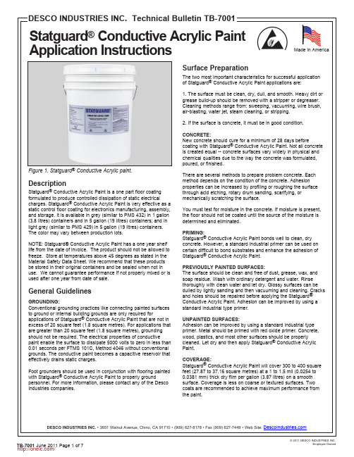
Made in AmericaThe two most important characteristics for successful applicationConductive Acrylic Paint applications are:1. The surface must be clean, dry, dull, and smooth. Heavy dirt or grease build-up should be removed with a stripper or degreaser. Cleaning methods range from: sweeping, vacuuming, wire brush, air-blasting, water jet, steam cleaning, or stripping.2. If the surface is concrete, it must be in good condition.New concrete should cure for a minimum of 28 days beforeConductive Acrylic Paint. Not all concrete is created equal -- concrete surfaces vary widely in physical and chemical qualities due to the way the concrete was formulated,There are several methods to prepare problem concrete. Each method depends on the condition of the concrete. Adhesion properties can be increased by profiling or roughing the surface through acid etching, rotary drum sanding, scarifying, or mechanically scratching the surface.You must test for moisture in the concrete. If moisture is present, the floor should not be coated until the source of the moisture isConductive Acrylic Paint bonds well to clean, dry concrete. However, a standard industrial primer can be used on certain difficult to bond substrates and enhance the adhesion of Conductive Acrylic Paint.PREVIOUSLY PAINTED SURFACES:The surface should be clean and free of dust, grease, wax, and soap residue. Wash with ordinary detergent and water. Rinse thoroughly with clean water and let dry. Glossy surfaces can be dulled by lightly sanding and then vacuuming and cleaning. Cracks and holes should be repaired before applying the Statguard Conductive Acrylic Paint. Adhesion can be improved by using atest area be coated to ensure that the adhesion and electrical of the paint is acceptable. (See Adhesion Testing, Figure 5.) If the 3. Saturate a 1/4” (6.35 mm) fine nap roller or an industrial brush ure must be above 50°F (10°C).Conductive Acrylic Paint is recommended for appropriate static protection.Mix any settled solids to produce a uniform grey color.Saturate a 1/4” fine nap roller with paint, remove excess paint and trapped bine separate cans into a larger A minimum number of strokes from the applicator is recommended.Figure 2. Paint application with roller.Figure 3. Spray paint application Clean UpWash applicators with water immediately after painting. Remove paint spills promptly with a wet cloth. Close container after each use. Keep container from freezing.Drying TimeIt is recommended that Statguard ® Conductive Acrylic Paint be allowed to dry at a temperature in excess of 45°F (7°C) until dry. A minimum of 1 to 2 hours drying time should be allowed before applying the second coat. The finish can be applied after 48-72 hours or until the last coat of paint is cured. Wait a minimum of 12 hours drying time after the last coat before allowing light traffic on the coated area. At high humidity levels, a longer drying time may be necessary. Do not force dry.MaintenanceUse sweeper, vacuum, or broom to remove dirt. Allow two weeks drying time before using a damp mop to clean the coated area. Do not use abrasive cleaners, floor rinse, or scrubbing machine to clean the floor.Finish/SealerDesco Statguard Conductive Acrylic Paint can be overcoated or sealed with Statguard Floor Finish static dissipative coating to increase durability, enhance shine, improve ease of maintenance, and seal out dirt and debris. Desco Statguard ® Conductive Light Grey Acrylic Paint needs the Statguard ® Floor Finish for gloss and ease of maintenance . Statguard ® is a polymer base floor finish/sealer that can be used as a top coat on the Conductive Acrylic Paint. Surface resistivity will then be in the 10E6-10E7 ohms range. Two coats are recommended. Three coats will improve electrical properties, durability and reduce frequency ofLead free, iron oxide, titanium dioxide and extenders 10.27 lbs per gallon (1.0 kilograms per Use a razor to cut into a painted, dried floor.3.Pull the tape off.Apply tape on the precut area.4.Examine the degree of paint separationfrom the concrete.Figure 5. Adhesion test on the painted floor.10E5 ohms/sq. per ASTM D257Static Charge Decay:<0.01 sec. per FTMS 101B, Method 4046Charge Generation:Zero per AATCC Step Test, Method 134-1979RTT:10E5 ohms per ANSI ESD-S7.1RTG:10E5 ohms per ANSI ESD-S7.1TestingTest patch areas should be tested for adhesion and electricalperformance of the paint before applying paint to the entire floor. To best ensure consistent results, the test should be done at various locations.ELECTRICAL PROPERTIES:Test the surface resistivity, point-to-point resistance, and resistance-to-ground properties of coated area per ANSI ESD-S7.1 test method. For quick and easy verification of the paint’s electrical properties, we recommend the use of our a Surface Resistance Test Kit (Figure 4). For more information contact any of the Desco Industries Inc. companies.ADHESION:Allow newly applied paint to dry a minimum of 48 hours before proceeding with the test. At humidity levels over 55% RH, allow 72 hours of drying time before testing. Use a razor to cut a cross or a few perpendicular lines over a 3” by 3” (75 mm by 75 mm) area on several spots of the thoroughly dried area. Use a piece of masking tape to cover the marked area. Make sure the tape is thoroughly adhered to the test area. Pull the tape off the surface and examine the amount of paint which has peeled off during the test. If any significant portion is transferred to the tape, better surface preparation (acid etching, cleaning or sanding) should be done on the substrate to enhance the adhesion.8. EXPOSURE CONTROL/PERSONAL EXPOSUREControl Parameters TLV-value 50 ppm maximum for n-butanol and 25 ppm for Ethylene GlycolMonobutyl EtherOther Regulations NoneMeasures For Technical Control Preferences of technical measure to prevent or control contact with the product.Isolating process and personnel, mechanical ventilation (dilution and localexhaust) and the regulation of process conditions. In case of non-prevention or non-control, a proper protective wearing should be used. Respiratory Protection Not required. Wear MSHA/NIOSH approved respirator where exposure limits areexceeded.Hand Protection Impervious/Neoprene GlovesEye Protection Chemical Splash Goggles (ANSI Z-87.1)Work/Hygienic Practices Wash hands before eating, smoking, or using washroom facilities9. PHYSICAL AND CHEMICAL PROPERTIESForm FluidColor Grey, OpaqueSmell MildpH 8.5Boiling Point at °C >100-101°C (212-214°F)Freezing Point at °C 0.0°C (32.0 °F)Flash Point at °C 65 °CExplosive Limits LEL: 0.8 UEL: 25.0Inflammability Limits N/A(vol.% in air)Solubility in water CompleteVOC per method 24 of EPA 2.3 -2.5 lbs VOC/ galVapor Pressure (mmHg) 92.43 mm @ 20 °CVapor Density (air=1) Heavier than airDensity at 20°C 8.17 lbs./gal or 1.14 g/cm3Specific Gravity (H20=1) 1.21Inflammability Classification according to OSHA and EC-regulations “non-flammable”Ignition Temperature 240.0 °CEvaporation Rate Slower than n-butyl acetate% Volatile by Volume 13.229%10. STABILITY AND REACTIVITYStability/Reactivity Stable product at normal conditionsConditions to avoid Temperatures above 49°C/120°F and below 1°C/34°F, Open flames and sparks. Materials to avoid Strong Oxidizing agents and alkalies.Hazardous Decomposition Oxides of carbon and nitrogen. If involved in fire (from other sources) could conceivably result in release of Carbon Dioxide and Carbon Monoxide fumes.11. TOXICOLOGICAL INFORMATIONIngredient-Material Description PEL TLV (twa) LD50 (mg/kg) LC50 (ppm)mg/m3 ppm (rat) (rbt) (rat)oral dermal inhalEthylene Glycol Monobutyl Ether * 50.0 0.0 25.0 470.0 220.0 0.0Butanol* 50.0 0.0 50.0 0.0 0.0 0.0Mineral Spirits 100.00 0.0 100.0 0.0 0.0 0.02-(2-Butoxyethoxy)ethanol 0.0 0.0 0.0 6560.0 4120.0 0.02-ethyl-1-Hexanol 0.0 0.0 0.0 3730 1970 0.0Ammonium Hydroxide 0.0 35.0 50.0 350.0 0.0 0.0*Listed Chemical Subject To Reporting Requirement of SARA Section 313 of Title III• Acute toxicity• Primary irritant effect:• On the skin: No irritant effect• On the eye: No irritant effect• Sensatization: No sensitizing effects known• Additional toxicological information:The product in not classified according to the calculation method of the General EU Classification guideline for Preparations as issued in the latest version. When used and handled according to specifications, the product does not have any harmful effects to our experience and the information provided to us.12. ECOLOGICAL INFORMATIONGeneral Notes:Water hazard class 1 (German Regulations) (self-assessment): slightly hazardous for water. Do not allow undiluted product or large quantities of it to reach ground water, water course or sewage system.Mobility The product is aqueous and will be separated in aqueous conditions Degradability N/ABioaccumulation Not likelyEcotoxicity None knownReference to BimSchV N/A13. DISPOSAL CONSIDERATIONSProduct Dike and collect material into plastic container. Water rinse and drain, flush smallamounts. Use sanitary landfill d isposal. Follow state and local regulations(RCRA; Subtitle D).Hazardous Waste Number Nonregulated14. TRANSPORT INFORMATIONThis product is not classified for transport under ADR/IMDG regulations.15. REGULATORY INFORMATIONLabeling according To EU guideline: Observe the general safety regulations when handeling chemicals. The product is not subject to identification regulations under EU Directives and the Ordinance on Hazardous Materials (Genman GefStoffV).National Regualtions:Waterhazard class: Water hazard class 1 (Self-assessment): slightly hazard for waterPhysical/Chemical Indication Non-flammableSafety Phrase (S2): keep away from children, (S7): keep containers well closed, (S24/25): avoidcontact with skin and eyes, (S45): in case of accident or if you feel unwell, seekmedical advice immediately, show label where possible, (S53): avoid exposureobtain special instruction before use, (S62): if swallowed, do not induce vomiting;seek medical advice immediately and show this container or label.EU Classification This product does not have to be classified according to the EU Regulations.(67/548/EEC-88/379/EEC)EINECS Status All components are included in the EINECS Inventories except cas #104-76-7 TSCA All ingredients of this product are listed or are excluded from the listing on the U.S. Toxic Substance Control Act (TSCA) Chemical Substance inventory.16. OTHER INFORMATIONFurther Information None KnownDisclaimerThe information given in this publication has been worked up to the best of the knowledge of Desco Industries Inc, as well as taking into consideration the applicable laws and regulations. We cannot anticipate all conditions under which this information and our products or the products of the manufacturers in combination with our products may be used. We accept no responsibility for the results obtained by the application information or the safety and suitability of our product or product combination with other products. Users are advised to make their own tests to determine the safety and suitability of each such product or product combination for their own purposes. Unless otherwise agreed in writing, we sell the products without warranty, and buyers end users assume responsibility and liability for loss or damage arising from the handling and use of our products, whether used alone or in combination with other products.分销商库存信息:DESCO1040810409。
S-80958中文资料

0.95 to 10.0‚u
; Products with detection voltage of 1.5‚uor more • Hysteresis characteristics 5% typ • Detection voltage 1.1 to 6.0 V (0.1V step) • Nch open-drain active low and CMOS active low output • SOT-23-5 Very-small plastic package
2
2
VDD Delay circuit
*
VDD OUT1源自*Delay circuit
*
OUT
1
VREF VSS
3 5
VREF VSS
3 5
CD
CD
*Parasitic diode Figure 2
Seiko Instruments Inc.
1
易网
BUILT-IN DELAY CIRCUIT HIGH-PRECISION VOLTAGE DETECTOR S-809 Series
Table 1
Detection voltage range (V) 1.1V±2.0% 1.2V±2.0% 1.3V±2.0% 1.4V±2.0% 1.5V±2.0% 1.6V±2.0% 1.7V±2.0% 1.8V±2.0% 1.9V±2.0% 2.0V±2.0% 2.1V±2.0% 2.2V±2.0% 2.3V±2.0% 2.4V±2.0% 2.5V±2.0% 2.6V±2.0% 2.7V±2.0% 2.8V±2.0% 2.9V±2.0% 3.0V±2.0% 3.1V±2.0% 3.2V±2.0% 3.3V±2.0% 3.4V±2.0% 3.5V±2.0% 3.6V±2.0% 3.7V±2.0% 3.8V±2.0% 3.9V±2.0% 4.0V±2.0% 4.1V±2.0% 4.2V±2.0% 4.3V±2.0% 4.4V±2.0% 4.5V±2.0% 4.6V±2.0% 4.7V±2.0% 4.8V±2.0% 4.9V±2.0% 5.0V±2.0% 5.1V±2.0% 5.2V±2.0% 5.3V±2.0% 5.4V±2.0% 5.5V±2.0% 5.6V±2.0% 5.7V±2.0% 5.8V±2.0% 5.9V±2.0% 6.0V±2.0% Hysteresis width VHYS typ.(V) 0.055 0.060 0.065 0.070 0.075 0.080 0.085 0.090 0.095 0.100 0.105 0.110 0.115 0.120 0.125 0.130 0.135 0.140 0.145 0.150 0.155 0.160 0.165 0.170 0.175 0.180 0.185 0.190 0.195 0.200 0.205 0.210 0.215 0.220 0.225 0.230 0.235 0.240 0.245 0.250 0.255 0.260 0.265 0.270 0.275 0.280 0.285 0.290 0.295 0.300 Nch Open Drain(Low) S-80911ANMP-D71-T2 S-80912ANMP-D72-T2 S-80913ANMP-DDA-T2 S-80914ANMP-DDB-T2 S-80915ANMP-DDC-T2 S-80916ANMP-DDD-T2 S-80917ANMP-DDE-T2 S-80918ANMP-DDF-T2 S-80919ANMP-DDG-T2 S-80920ANMP-DDH-T2 S-80921ANMP-DDJ-T2 S-80922ANMP-DDK-T2 S-80923ANMP-DDL-T2 S-80924ANMP-DDM-T2 S-80925ANMP-DDN-T2 S-80926ANMP-DDP-T2 S-80927ANMP-DDQ-T2 S-80928ANMP-DDR-T2 S-80929ANMP-DDS-T2 S-80930ANMP-DDT-T2 S-80931ANMP-DDV-T2 S-80932ANMP-DDW-T2 S-80933ANMP-DDX-T2 S-80934ANMP-DDY-T2 S-80935ANMP-DDZ-T2 S-80936ANMP-DD0-T2 S-80937ANMP-DD1-T2 S-80938ANMP-DD2-T2 S-80939ANMP-DD3-T2 S-80940ANMP-DD4-T2 S-80941ANMP-DD5-T2 S-80942ANMP-DD6-T2 S-80943ANMP-DD7-T2 S-80944ANMP-DD8-T2 S-80945ANMP-DD9-T2 S-80946ANMP-DJA-T2 S-80947ANMP-DJB-T2 S-80948ANMP-DJC-T2 S-80949ANMP-DJD-T2 S-80950ANMP-DJE-T2 S-80951ANMP-DJF-T2 S-80952ANMP-DJG-T2 S-80953ANMP-DJH-T2 S-80954ANMP-DJJ-T2 S-80955ANMP-DJK-T2 S-80956ANMP-DJL-T2 S-80957ANMP-DJM-T2 S-80958ANMP-DJN-T2 S-80959ANMP-DJP-T2 S-80960ANMP-DJQ-T2 CMOS Output(Low) S-80911ALMP-D51-T2 S-80912ALMP-D52-T2 S-80913ALMP-DAA-T2 S-80914ALMP-DAB-T2 S-80915ALMP-DAC-T2 S-80916ALMP-DAD-T2 S-80917ALMP-DAE-T2 S-80918ALMP-DAF-T2 S-80919ALMP-DAG-T2 S-80920ALMP-DAH-T2 S-80921ALMP-DAJ-T2 S-80922ALMP-DAK-T2 S-80923ALMP-DAL-T2 S-80924ALMP-DAM-T2 S-80925ALMP-DAN-T2 S-80926ALMP-DAP-T2 S-80927ALMP-DAQ-T2 S-80928ALMP-DAR-T2 S-80929ALMP-DAS-T2 S-80930ALMP-DAT-T2 S-80931ALMP-DAV-T2 S-80932ALMP-DAW-T2 S-80933ALMP-DAX-T2 S-80934ALMP-DAY-T2 S-80935ALMP-DAZ-T2 S-80936ALMP-DA0-T2 S-80937ALMP-DA1-T2 S-80938ALMP-DA2-T2 S-80939ALMP-DA3-T2 S-80940ALMP-DA4-T2 S-80941ALMP-DA5-T2 S-80942ALMP-DA6-T2 S-80943ALMP-DA7-T2 S-80944ALMP-DA8-T2 S-80945ALMP-DA9-T2 S-80946ALMP-DEA-T2 S-80947ALMP-DEB-T2 S-80948ALMP-DEC-T2 S-80949ALMP-DED-T2 S-80950ALMP-DEE-T2 S-80951ALMP-DEF-T2 S-80952ALMP-DEG-T2 S-80953ALMP-DEH-T2 S-80954ALMP-DEJ-T2 S-80955ALMP-DEK-T2 S-80956ALMP-DEL-T2 S-80957ALMP-DEM-T2 S-80958ALMP-DEN-T2 S-80959ALMP-DEP-T2 S-80960ALMP-DEQ-T2
19218;中文规格书,Datasheet资料

Jewel ® Workstation Continuous Mini Monitor DescriptionWorkstation Continuous Mini Monitor Figure 1. Desco 19218 Jewel ® Workstation Continuous Made in AmericaA broken wrist strap may expose products to ESD over an entire shift if it is checked only at shift changeESD MATPush and Clinch Snaps1-5/16"Figure 2. Installation of push and clinch snaps to worksurfaceNOTE: Install the monitor to the worksurface by aligning one snap at a time and applying a downward force directly above that snap.WorksurfaceMonitors worksurface connectionFigure 3. Installation of the monitor to the worksurface one snap at a timeThe following procedure will outline how to correctly wire Workstation Continuous Mini Monitor so as to properly monitor an ESD protected workstation.1. Confirm that the worksurface surface resistance is 5 x 10E8 Ohms or less and has a conductive layer.2. A convenient 120 VAC outlet should be located and tested for proper wiring and grounding. Werecommend the Desco 98130 AC Outlet Analyzer to verify proper wiring and ground.AC AdapterESD MATPark SnapFigure 4. Operating the Jewel® Workstation ContinuousHand Lotion. When leaving the area, a person can take the coil cord along or leave it attached to themonitor in park position.NOTE: Removing the banana plug from the monitor’s operator jack will disable the audio alarm.It is recommended that you use the Park Snap rather than continuously removing the Banana Plug from its jack. Doing so will increase the life span of the operator jack. If your process requires the constant insertion and removal of the banana plug, please contact your Desco Representative for alternate solutions.Specifications:Test range of monitored circuit:500K - 10M ohms†Worksurface Limit*:Set to 500 Megohms ± 20%Operating Voltage:24VAC, 50-60 HzWrist strap open circuit voltage:1.2 Volts peak to peak @ 1-2 MicroAmpsMat test open circuit voltage:5 - 7.5 VoltsResponse time to alarm:<50 mSOperating Temperature:32ºF - 100ºFHumidity Range:0-95% RH, non- c ondensingDimensions:2.77" L x 2.07" W x .71" H† This cannot be verified with standard DC test equipment. The continuous monitor is an impedance sensing device and the limits are determined by the magnitude and angle of the impedance.*Contact factory for special limits.NOTE: Worksurface must have a conductive layer such as Dual Layer Rubber or Dissipative 3-Layer Vinyl or Micastat® Dissipative Laminate with conductive buried layers. Desco continuous monitors are not recommended for use with homogeneous matting.Maintenance and CalibrationThe Jewel® Workstation Continuous Mini Monitor is solid state and designed to be maintenance free. It is calibrated to NIST traceable standards. There are no user adjustments necessary. Because of the wave distortion impedance sensing nature of the test circuit, special equipment is required for calibration. We recommend that calibration be performed annually using the Desco 98220 Continuous Monitor Calibration Unit. The Calibration Unit is a most important product which allows the customer to perform NIST traceable calibration on continuous monitors. The 98220 is designed to be used on the shop floor at the workstation, virtually eliminating downtime, verifying that the continuous monitor is operating within tolerances. The 98220 provides a simple and quick means to assure compliance verificaton Per ANSI/ESD S20.20 Table 3 per ESD TR53.Limited WarrantyDesco expressly warrants that for a period of one (1) year from the dateof purchase Desco Continuous Monitors will be free of defects in material(parts) and workmanship (labor). Within the warranty period, a creditfor purchase of replacement Desco Continuous Monitors, or, at Desco’soption, the Continuous Monitor will be repaired or replaced free of charge.If product credit is issued, the amount will be calculated by multiplying the unused portion of the expected one year life times the original unit purchase price. Call Customer Service at 909-627-8178 (Chino, CA) or 781-821-8370 (Canton, MA) for Return Material Authorization (RMA) and proper shipping instructions and address. Include a copy of your original packing slip,invoice, or other proof of date of purchase. Any unit under warranty should be shipped prepaid to the Desco factory. Warranty replacements will takeapproximately two weeks.If your unit is out of warranty, Desco will quote repair charges necessaryto bring your unit up to factory standards. Call Customer Service at 909-627-8178 (Chino, CA) or 781-821-8370 (Canton, MA) for a Return Material Authorization (RMA) and proper shipping instructions and address.Warranty ExclusionsTHE FOREGOING EXPRESS WARRANTY IS MADE IN LIEU OFALL OTHER PRODUCT WARRANTIES, EXPRESSED AND IMPLIED,INCLUDING MERCHANTABILITY AND FITNESS FOR A PARTICULARPURPOSE WHICH ARE SPECIFICALLY DISCLAIMED. The expresswarranty will not apply to defects or damage due to accidents, neglect,misuse, alterations, operator error, or failure to properly maintain, clean or repair products.Limit of LiabilityIn no event will Desco or any seller be responsible or liable for anyinjury, loss or damage, direct or consequent, arising out of the use of orthe inability to use the product. Before using, users shall determine thesuitability of the product for their intended use, and users assume all riskand liability whatsoever in connection therewith.分销商库存信息: DESCO19218。
0878321014;中文规格书,Datasheet资料
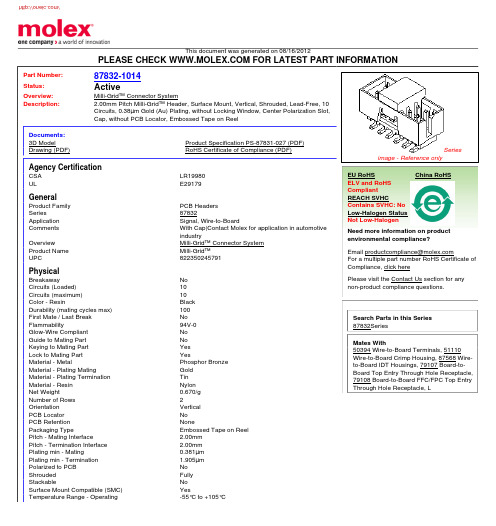
This document was generated on 08/16/2012PLEASE CHECK FOR LATEST PART INFORMATIONPart Number:87832-1014Status:ActiveOverview:Milli-Grid™ Connector SystemDescription:2.00mm Pitch Milli-Grid™ Header, Surface Mount, Vertical, Shrouded, Lead-Free, 10Circuits, 0.38µm Gold (Au) Plating, without Locking Window, Center Polarization Slot,Cap, without PCB Locator, Embossed Tape on ReelDocuments:3D ModelProduct Specification PS-87831-027 (PDF)Drawing (PDF)RoHS Certificate of Compliance (PDF)Agency CertificationCSA LR19980ULE29179GeneralProduct Family PCB Headers Series87832Application Signal, Wire-to-BoardComments With Cap|Contact Molex for application in automotive industryOverviewMilli-Grid™ Connector System Product Name Milli-Grid™UPC822350245791PhysicalBreakawayNo Circuits (Loaded)10Circuits (maximum)10Color - ResinBlack Durability (mating cycles max)100First Mate / Last Break No Flammability94V-0Glow-Wire Compliant No Guide to Mating Part No Keying to Mating Part Yes Lock to Mating Part YesMaterial - MetalPhosphor Bronze Material - Plating MatingGold Material - Plating Termination Tin Material - Resin Nylon Net Weight0.670/g Number of Rows 2Orientation Vertical PCB Locator No PCB Retention NonePackaging TypeEmbossed Tape on Reel Pitch - Mating Interface2.00mm Pitch - Termination Interface 2.00mm Plating min - Mating0.381µm Plating min - Termination 1.905µm Polarized to PCB No Shrouded Fully StackableNo Surface Mount Compatible (SMC)YesTemperature Range - Operating-55°C to +105°CSeriesimage - Reference onlyEU RoHSChina RoHSELV and RoHS Compliant REACH SVHCContains SVHC: No Low-Halogen Status Not Low-HalogenNeed more information on product environmental compliance?Email productcompliance@For a multiple part number RoHS Certificate of Compliance, click herePlease visit the Contact Us section for any non-product compliance questions.Search Parts in this Series 87832SeriesMates With50394 Wire-to-Board Terminals, 51110Wire-to-Board Crimp Housing, 87568 Wire-to-Board IDT Housings, 79107 Board-to-Board Top Entry Through Hole Receptacle,79108 Board-to-Board FFC/FPC Top Entry Through Hole Receptacle, LTermination Interface: Style Through Hole and Surface MountElectricalCurrent - Maximum per Contact2AVoltage - Maximum125VSolder Process DataDuration at Max. Process Temperature (seconds)10Lead-free Process Capability Reflow Capable (SMT only)Max. Cycles at Max. Process Temperature1Process Temperature max. C260Material InfoReference - Drawing NumbersProduct Specification PS-87831-027Sales Drawing SD-87832-008This document was generated on 08/16/2012PLEASE CHECK FOR LATEST PART INFORMATION分销商库存信息: MOLEX 0878321014。
0878321822;中文规格书,Datasheet资料
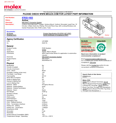
This document was generated on 08/16/2012PLEASE CHECK FOR LATEST PART INFORMATIONPart Number:87832-1822Status:ActiveOverview:Milli-Grid™ Connector SystemDescription:2.00mm Pitch Milli-Grid™ Header, Surface Mount, Vertical, Shrouded, Lead-Free, 18Circuits, 0.38µm Gold (Au) Plating, Pick-and-Place Cap, with Locking Windows and Center Polarization Slot, PCB Locator, TubeDocuments:3D ModelProduct Specification PS-87831-027 (PDF)Drawing (PDF)RoHS Certificate of Compliance (PDF)Agency CertificationCSA LR19980ULE29179GeneralProduct Family PCB Headers Series87832Application Signal, Wire-to-BoardComments With Cap|Contact Molex for application in automotive industryOverviewMilli-Grid™ Connector System Product Name Milli-Grid™UPC822348352173PhysicalBreakawayNo Circuits (Loaded)18Circuits (maximum)18Color - ResinBlack Durability (mating cycles max)100First Mate / Last Break No Flammability94V-0Glow-Wire Compliant No Guide to Mating Part No Keying to Mating Part Yes Lock to Mating Part YesMaterial - MetalPhosphor Bronze Material - Plating MatingGold Material - Plating Termination Tin Material - Resin Nylon Net Weight0.981/g Number of Rows 2Orientation Vertical PCB Locator No PCB Retention None Packaging TypeTube Pitch - Mating Interface2.00mm Pitch - Termination Interface 2.00mm Plating min - Mating0.381µm Plating min - Termination 1.905µm Polarized to PCB No Shrouded Fully StackableNo Surface Mount Compatible (SMC)YesTemperature Range - Operating-55°C to +105°CSeriesimage - Reference onlyEU RoHSChina RoHSELV and RoHS Compliant REACH SVHCContains SVHC: No Low-Halogen Status Not Low-HalogenNeed more information on product environmental compliance?Email productcompliance@For a multiple part number RoHS Certificate of Compliance, click herePlease visit the Contact Us section for any non-product compliance questions.Search Parts in this Series 87832SeriesMates With50394 Wire-to-Board Terminals, 51110Wire-to-Board Crimp Housing, 87568 Wire-to-Board IDT Housings, 79107 Board-to-Board Top Entry Through Hole Receptacle,79108 Board-to-Board FFC/FPC Top Entry Through Hole Receptacle, LTermination Interface: Style Through Hole and Surface MountElectricalCurrent - Maximum per Contact2AVoltage - Maximum125VSolder Process DataDuration at Max. Process Temperature (seconds)10Lead-free Process Capability Reflow Capable (SMT only)Max. Cycles at Max. Process Temperature1Process Temperature max. C260Material InfoReference - Drawing NumbersProduct Specification PS-87831-027Sales Drawing SD-87832-006This document was generated on 08/16/2012PLEASE CHECK FOR LATEST PART INFORMATION分销商库存信息: MOLEX 0878321822。
5082-2830中文资料
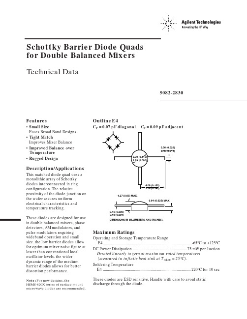
Schottky Barrier Diode Quads for Double Balanced MixersTechnical DataFeatures• Small SizeEases Broad Band Designs• Tight MatchImproves Mixer Balance• Improved Balance overTemperature• Rugged DesignDescription/Applications This matched diode quad uses a monolithic array of Schottky diodes interconnected in ring configuration. The relative proximity of the diode junction on the wafer assures uniform electrical characteristics and temperature tracking.These diodes are designed for use in double balanced mixers, phase detectors, AM modulators, and pulse modulators requiring wideband operation and small size. the low barrier diodes allow for optimum mixer noise figure at lower than conventional local oscillator levels. the wider dynamic range of the medium barrier diodes allows for better distortion performance.Note: For new designs, theHSMS-820X series of surface mount microwave diodes are recommended.5082-2830Outline E4C P = 0.07 pF diagonal C P = 0.09 pF adjacentDIMENSIONS IN MILLIMETERS AND (INCHES).Maximum RatingsOperating and Storage Temperature RangeE4........................................................................................-65°C to +125°C DC Power Dissipation.....................................................75 mW per Juction Derated linearly to zero at maximum rated temperatures(measured in infinite heat sink at T CASE = 25°C).Soldering TemperatureE4.......................................................................................220°C for 10 sec These diodes are ESD sensitive. Handle with care to avoid static discharge through the diode.Electrical Specifications at TA = 25°CMaximum Measured MaximumMaximum Part Maximum Capacitance V FDynamic Forward Number Capacitance Difference Difference Resistance Voltage 5082-Package Barrier C M (pF)∆C M (pF)∆V F (mV)R D (Ω)V F (V)2830E4Medium0.5 Typ.0.2020120.40Test V R = 0I F = 5 mAI F = 1 mA Conditionsf = 1 MHzbetween Adjacent LeadsMeasured between Adjacent LeadsTypical Parameterswhere I B is the bias current in milliamperes. The series resistance is independent of current.The dynamic resistance is more easily measured. If seriesresistance is specified, it is usually obtained by subtracting the calculated junction resistance from the measured dynamic resistance.Quad CapacitanceCapacitance of Schottky diode quads is measured using an HP4271 LCR meter. Thisinstrument effectively isolates individual diode branches from the others, allowing accuratecapacitance measurement of each branch or each diode. The conditions are: 20 mV R.M.S.voltage at 1 MHz. Agilent defines this measurement as “CM”, and it is equivalent to the capacitance of the diode by itself. The equivalent diagonal and adjacent capacitances can then bePackage CharacteristicsThe Agilent outline E4 package is designed for MIC, Microstrip, and Stripline use from dc through C-Band. The leads provide a good continuity of transmission line impedance to the monolithic diode array. The leads are tin plated copper.Dynamic and Series ResistanceSchottky diode resistance may be expressed as series resistance, R S ,or as dynamic ressitance, R D .These two terms are related by the equationR D = R S = R jwhere R j is the resistance of the junction. Junction resistance of a diode with DC bias is quite accurately calculated byR j = 26/I Bcalculated by the formulas given CThe equivalent adjacentcapacitance is the capacitance between points A and C in figure below. This capacitance is calculated using the following formula1C ADJACENT = C 1 + ____________1 1 1–– + –– + –– C2 C 3C 4SPICE ParametersParameterUnits 5082-2830B V V 10C J0pF 4E G eV 0.69I BV A 10E -5I S A 2 x 10E -10N 1.08R S Ω6P B V0.65P T 2M0.5 Data subject to change.Copyright © 1999 Agilent Technologies 5965-8848E (11/99)。
0878312629;中文规格书,Datasheet资料
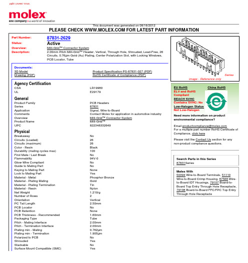
This document was generated on 08/16/2012PLEASE CHECK FOR LATEST PART INFORMATIONPart Number:87831-2629Status:ActiveOverview:Milli-Grid™ Connector SystemDescription:2.00mm Pitch Milli-Grid™ Header, Vertical, Through Hole, Shrouded, Lead-Free, 26Circuits, 0.76µm Gold (Au) Plating, Center Polarization Slot, with Locking Windows,PCB Locator, TubeDocuments:3D ModelProduct Specification PS-87831-027 (PDF)Drawing (PDF)RoHS Certificate of Compliance (PDF)Agency CertificationCSA LR19980ULE29179GeneralProduct Family PCB Headers Series87831Application Signal, Wire-to-BoardComments Contact Molex for application in automotive industry OverviewMilli-Grid™ Connector System Product Name Milli-Grid™UPC822348332649PhysicalBreakawayNo Circuits (Loaded)26Circuits (maximum)26Color - ResinBlack Durability (mating cycles max)100First Mate / Last Break No Flammability94V-0Glow-Wire Compliant No Guide to Mating Part No Keying to Mating Part None Lock to Mating Part YesMaterial - MetalPhosphor Bronze Material - Plating MatingGold Material - Plating Termination Tin Material - Resin Nylon Net Weight1.219/g Number of Rows 2Orientation Vertical PC Tail Length 2.50mm PCB Locator No PCB RetentionNone PCB Thickness - Recommended 1.60mm Packaging TypeTube Pitch - Mating Interface2.00mm Pitch - Termination Interface 2.00mm Plating min - Mating0.762µm Plating min - Termination 1.905µm Polarized to PCB No Shrouded Yes StackableNo Surface Mount Compatible (SMC)YesSeriesimage - Reference onlyEU RoHSChina RoHSELV and RoHS Compliant REACH SVHCContains SVHC: No Low-Halogen Status Not Low-HalogenNeed more information on product environmental compliance?Email productcompliance@For a multiple part number RoHS Certificate of Compliance, click herePlease visit the Contact Us section for any non-product compliance questions.Search Parts in this Series 87831SeriesMates With50394 Wire-to-Board Terminals, 51110Wire-to-Board Crimp Housing, 87568 Wire-to-Board IDT Housings, 79107 Board-to-Board Top Entry Through Hole Receptacle,79108 Board-to-Board FFC/FPC Top Entry Through Hole ReceptacleTemperature Range - Operating-55°C to +105°CTermination Interface: Style Through HoleElectricalCurrent - Maximum per Contact2AVoltage - Maximum125VMaterial InfoReference - Drawing NumbersProduct Specification PS-87831-027Sales Drawing SD-87831-020This document was generated on 08/16/2012PLEASE CHECK FOR LATEST PART INFORMATION分销商库存信息: MOLEX 0878312629。
TL48S-090-0888中文资料
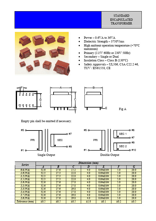
A
67.0 67.0 67.0 Max.
L H
B
56.0 56.0 56.0 Max.
E
∅0.8 ∅0.8 ∅0.8 ±0.1
Dimension (mm) F G H
5.0 5.0 5.0 ±0.2 32.5 32.5 32.5 ±0.5 ∅4.2 ∅4.2 ∅4.2 ±0.2
I
82.5 82.5 82.5 Max.
J
72.5 72.5 72.5 ±0.5
K
11.2 11.2 11.2 ±0.5
L
43.5 43.5 43.5 ±0.5
46.5 46.5 46.5 Max.
E
F G
N
B Mx4
I
O
C
A K
D
J
Fig L
Empty pin shall be omitted if necessary.
#8 130 C #10 PRI SEC #15 #1 #1 PRI SEC 2 #16 #8 130 C SEC 1 #10 #15 #9
Double Output
Dimension (mm) D
4.0 4.0 4.0 4.0 4.0 4.0 4.0 4.0 4.0 4.0 ±1.0
A
32.6 32.3 32.3 32.3 32.6 32.6 32.6 32.6 32.6 32.6 ±0.5
B
27.6 27.3 27.3 27.3 27.6 27.6 27.6 27.6 27.6 27.6 ±0.5
F
#1 #2 #3 #4 #5
A
B
G
#10 #9 #8 #7 #6
C
D
1 2F
- 1、下载文档前请自行甄别文档内容的完整性,平台不提供额外的编辑、内容补充、找答案等附加服务。
- 2、"仅部分预览"的文档,不可在线预览部分如存在完整性等问题,可反馈申请退款(可完整预览的文档不适用该条件!)。
- 3、如文档侵犯您的权益,请联系客服反馈,我们会尽快为您处理(人工客服工作时间:9:00-18:30)。
This document was generated on 05/04/2011
PLEASE CHECK FOR LATEST PART INFORMATION
Part Number:0908581280Status:Active
Overview:rast_5_connector_system
Description:
5.00mm (.197") Pitch Appli-Mate RAST 5 Header, Vertical, 4 Circuits, Reference K65
Documents:3D Model
Packaging Specification PK-90833-001 (PDF)Drawing (PDF)
Packaging Specification PK-90858-001 (PDF)Product Specification PS-99020-0037 (PDF)
RoHS Certificate of Compliance (PDF)
Agency Certification
CSA LR19980UL
E29179
General
Product Family PCB Headers Series
90858
Application Power, Wire-to-Board Overview
rast_5_connector_system Product Name
RAST 5Physical
Breakaway
No Circuits (Loaded)4Circuits (maximum)4
Color - Resin
Natural Durability (mating cycles max)10First Mate / Last Break No Flammability
94V-0Glow-Wire Compliant No Guide to Mating Part No Keying to Mating Part None Lock to Mating Part None Material - Metal
Brass Material - Plating Mating
Tin Material - Plating Termination Tin Number of Rows 1
Orientation Vertical
PC Tail Length 3.50mm (.138")PCB Locator Yes PCB Retention
None
PCB Thickness - Recommended 1.40mm (.055")Packaging Type
Bag
Pitch - Mating Interface 5.00mm (.197")Polarized to PCB Yes Shrouded Fully Stackable
Yes Surface Mount Compatible (SMC)No
Temperature Range - Operating -20°C to +85°C Termination Interface: Style
Through Hole Electrical
Current - Maximum per Contact 16A Voltage - Maximum
250V
Material Info
Series
image - Reference only
EU RoHS
China RoHS
ELV and RoHS Compliant REACH SVHC Not Reviewed
Low-Halogen Status Not Reviewed
Need more information on product environmental compliance?
Email productcompliance@
For a multiple part number RoHS Certificate of Compliance, click here
Please visit the Contact Us section for any non-product compliance questions.
Search Parts in this Series 90858Series
Mates With
Appli-Mate 5.0 IDT Connector System Female Receptacle 90835 , 90833
Reference - Drawing Numbers
Packaging Specification PK-90833-001, PK-90858-001
Product Specification PS-99020-0037
Sales Drawing SD-90858-001
This document was generated on 05/04/2011
PLEASE CHECK FOR LATEST PART INFORMATION
分销商库存信息: MOLEX 0908581280。
