NE334S01_00中文资料
MSMA012资料
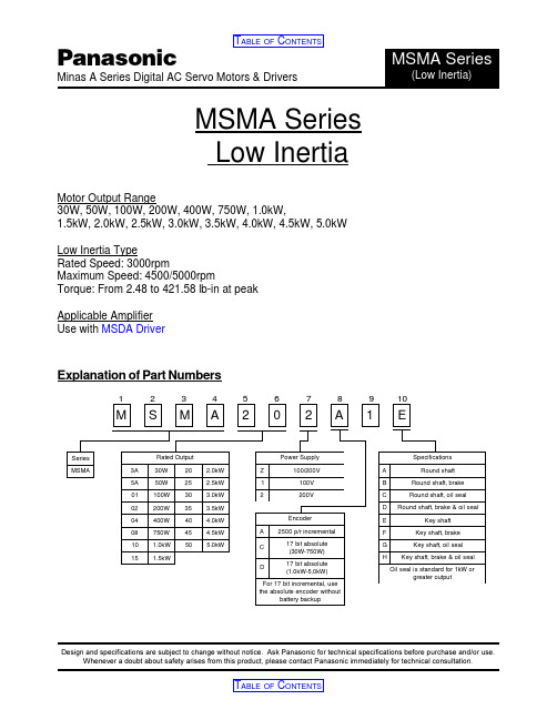
Radial Load Thrust A Thrust B
147.0 N
88.0 N
117.6 N
33.0 lb
19.8 lb
26.4 lb
During Operation of Motor
Radial Load Thrust Load
49.0 N
29.4 N
11.0 lb
6.6 lb
TABLE OF CONTENTS
元器件交易网
TABLE OF CONTENTS
Panasonic
Minas A Series Digital AC Servo Motors & Drivers
MSMA Series
(Low Inertia)
MSMA3AZccc - 30W/100V or 200V
Specifications
(4.803) (3.819) (2.717)
Note: Dimensions reflect incremental type motor. For absolute type motor dimensions, refer to the motor specification.
0.15 Nm
Intermittent Duty Zone
Continuous Duty Zone
1000
3000
5000 r/min.
Temperature Characteristics
Without Oil Seal
Rated T orque(%) 100
10 20 30 40 Ambient T emp.(C)
«««Selects cable length 003 = 3m (9.84ft) 005 = 5m (16.40ft) 010 = 10m (32.81ft) 020 = 20m (65.62ft)
SM-4中文资料
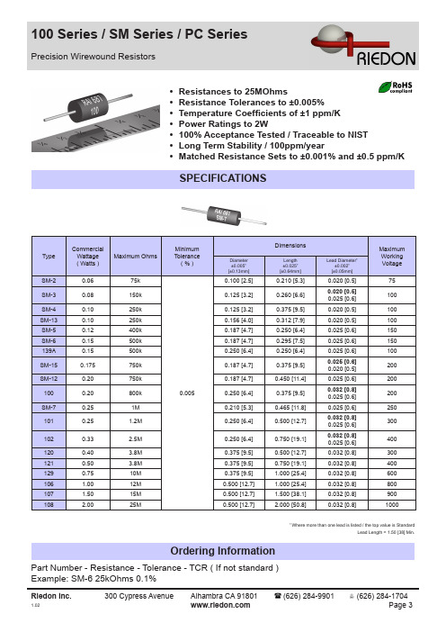
SPECIFICATIONS
Type
Commercial Wattage ( Watts ) 0.06 0.08 0.10 0.10 0.12 0.15 0.15 0.175 0.20 0.20 0.25 0.25 0.33 0.40 0.50 0.75 1.00 1.50 2.00
Maximum Ohms
0.032 [0.8] 0.032 [0.8] 0.025 [0.6] 0.032 [0.8]
0.125 [3.2] 0.250 [6.4] 0.150 [3.8] 0.400 [10.2]
1
Lead Length = 1.00 [25] Min.
Specification
Tolerances Temperature Coefficient ( Standard )
100PC 130PC 131PC 1250 [6.4] 0.250 [6.4] 0.250 [6.4] 0.375 [9.5] 0.500 [12.7]
0.375 [9.5] 0.312 [7.9] 0.312 [7.9] 0.500 [12.7] 0.500 [12.7] 0.500 [12.7]
Where more than one lead is listed / the top value is Standard Lead Length = 1.50 [38] Min.
Ordering Information
Part Number - Resistance - Tolerance - TCR ( If not standard ) Example: SM-6 25kOhms 0.1%
元器件交易网
100 Series / SM Series / PC Series
MB2411E1W01;MB2411E1W03;MB2411E1G01;MB2411S1W01;MB2411E1W03-FA;中文规格书,Datasheet资料
A
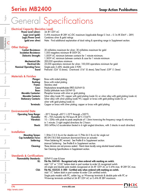
Rated 3A @ 125V AC & 0.4VA max @ 28V
Power Level (silver): 3A @ 125V AC Logic Level (gold): 0.4VA maximum @ 28V AC/DC maximum (Applicable Range 0.1mA ~ 0.1A @ 20mV ~ 28V)
Logic/Power Level: Combines silver & gold ratings (gold over silver) Note: Find additional explanation of dual rating & operating range in Supplement section.
To g g l e s
Rockers
Keylocks Programmable Illuminated PB Pushbuttons
Rotaries
Series MB2400
Snap-Action Pushbuttons
General Specifications
Electrical Capacity (Resistive Load)
Slides
Ta c t i l e s
Tilt
To u c h
Supplement Accessories Indicators
C96 /
w w
To g g l e s
Rockers
Keylocks Programmable Illuminated PB Pushbuttons
TYPICAL SWITCH ORDERING EXAMPLE
MB24 11 E1 W 01 F A
贴片元件标记对应型号资料
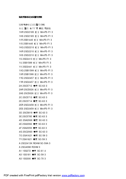
贴片元件标记对应型号资料贴片元件标记对应型号资料标记型号生产厂家封装引脚数1HR 2SD2185 松下MiniP3-F1 3 1HS 2SD2185 松下MiniP3-F1 3 1IR 2SB1440 松下MiniP3-F1 3 1IS 2SB1440 松下MiniP3-F1 3 1KQ 2SD2210 松下MiniP3-F1 3 1KR 2SD2210 松下MiniP3-F1 3 1KS 2SD2210 松下MiniP3-F1 3 1S 2SD2413 松下MiniP3-F1 3 1U 2SB1589 松下MiniP3-F1 3 1V 2SD2441 松下MiniP3-F1 3 1XQ 2SB1599 松下MiniP3-F1 3 1XR 2SB1599 松下MiniP3-F1 3 1YQ 2SD2457 松下MiniP3-F1 3 1YR 2SD2457 松下MiniP3-F1 3 2A 2SC5712 東芝SC-63 32AR 2SC5026 松下MiniP3-F1 3 2AS 2SC5026 松下MiniP3-F1 3 2C 2SC5713 東芝SC-63 32E 2SC5714 東芝SC-63 32ER 2SD2459 松下MiniP3-F1 3 2ES 2SD2459 松下MiniP3-F1 3 3D 2SC5819 東芝SC-63 33E 2SC5785 東芝SC-63 34D 2SA2069 東芝SC-63 34E 2SA2066 東芝SC-63 34F 2SA2059 東芝SC-63 34G 2SC2060 東芝SC-63 37O 2SA1621 東芝SC-59 37Y 2SA1621 東芝SC-59 3A 2SC2413K ROHM SC-59A 3 A 2SC4098 ROHM 3A1 1SS272 東芝SC-61 4A3 1SS181 東芝SC-59 3A3 1SS300 東芝SC-70 3A4 1SS319 東芝SC-61 4A4 1SS383 東芝4A5 1SS384 東芝SOT-343 4A5 1SS391 東芝SC-61 4A6 HN2S01F 東芝SC-74 6A6 HN2S01FU 東芝SC-88 6 A7 1SS402 東芝SOT-343 4A9 1SS294 東芝SC-59 3AL 2SA1971 東芝SC-63 3AL 2SC5307 東芝SC-63 3AN 2SC2532 東芝SC-59 3 AO 2SA2880 東芝SC-63 3 AQ 2SB766 松下MiniP3-F1 3 AR 2SB766 松下MiniP3-F1 3 AS 2SB766 松下MiniP3-F1 3 AU 2SB804 NEC SC-62 3AV 2SB804 NEC SC-62 3AW 2SB804 NEC SC-62 3AY 2SA2880 東芝SC-63 3B 2CS4081 ROHM 3B 2SC2412K ROHM SC-59A 3 B3 1SS184 東芝SC-59 3B3 1SS301 東芝SC-70 3B9 1SS311 東芝SC-59 3B9 1SS397 東芝SC-70 3BD 1SS271 東芝SC-59 3BE 1SV172 東芝BF 1SS268 東芝SC-59 3BG 1SS269 東芝SC-59 3BH 1SS295 東芝SC-59 3BO 2SA1200 東芝SC-63 3 BQ 2SB766A 松下MiniP3-F1 3 BR 2SB766A 松下MiniP3-F1 3 BS 2SB766A 松下MiniP3-F1 3 BU 2SD1005 NEC SC-62 3BU DA228K ROHM SC-59 3 BU DA228U ROHM SC-70 3 BV 2SD1005 NEC SC-62 3BW 2SD1005 NEC SC-62 3BY 2SA1200 東芝SC-63 3C 2SC2411K ROHM SC-59A 3C 2SC4097 ROHM 3C1 1SS352 東芝C1 1SS387 東芝C3 1SS226 東芝SC-59 3C9 1SS307 東芝SC-59 3CEO 2SC3325 東芝SC-59 3 CEY 2SC3325 東芝SC-59 3CG 2SA1163 東芝SC-59 3CK 2SD999 NEC SC-62 3CL 2SD999 NEC SC-62 3CM 2SD999 NEC SC-62 3CO 2SC2881 東芝SC-63 3CO 2SC4209 東芝SC-59 3CQ 2SB767 松下MiniP3-F1 3 CR 2SB767 松下MiniP3-F1 3 CY 2SC2881 東芝SC-63 3CY 2SC4209 東芝SC-59 3D 2SA1037KLN ROHM SC-59A 3 D3 1SS187 東芝SC-59 3DG 2SC2713 東芝SC-59 3DK 2SB798 NEC SC-62 3DL 2SB798 NEC SC-62 3DM 2SB798 NEC SC-62 3DO 2SA1201 東芝SC-63 3DQ 2SB789 松下MiniP3-F1 3 DR 2SB789 松下MiniP3-F1 3 DY 2SA1201 東芝SC-63 3E3 1SS190 東芝SC-59 3EK 2SD1001 NEC SC-62 3EL 2SD1001 NEC SC-62 3EM 2SD1001 NEC SC-62 3EO 2SC2882 東芝SC-63 3EQ 2SB789A 松下MiniP3-F1 3 ER 2SB789A 松下MiniP3-F1 3 EX 2SD2402 NEC SC-62 3EY 2SC2882 東芝SC-63 3EY 2SD2402 NEC SC-62 3EZ 2SD2402 NEC SC-62 3F 2SA1037K ROHM SC-59A 3 F 2SA1576 ROHM 3F3 1SS193 東芝SC-59 3F5 1SS250 東芝SC-59 3F5 1SS370 東芝SC-70 3F5 1SS403 東芝SOD-323 2F9 1SS321 東芝SC-59 3FK 2SB800 NEC SC-62 3FL 2SB800 NEC SC-62 3FM 2SB800 NEC SC-62 3FO 2SA1202 東芝SC-63 3FX 2SB1571 NEC SC-62 3FY 2SA1202 東芝SC-63 3FY 2SB1571 NEC SC-62 3FZ 2SB1571 NEC SC-62 3G3 1SS196 東芝SC-59 3G3 2SA1455K ROHM SC-59A 3 GK 2SD1615 NEC SC-62 3GL 2SD1615 NEC SC-62 3GM 2SD1615 NEC SC-62 3 GO 2SC2883 東芝SC-63 3 GP 2SD1615A NEC SC-62 3 GQ 2SD1615A NEC SC-62 3 GX 2SD2403 NEC SC-62 3GY 2SC2883 東芝SC-63 3GY 2SD2403 NEC SC-62 3GZ 2SD2403 NEC SC-62 3H9 1SS344 東芝SC-59 3HK 2SD1006 NEC SC-62 3HL 2SD1006 NEC SC-62 3HM 2SD1006 NEC SC-62 3 HO 2SA1203 東芝SC-63 3HP 2SD1007 NEC SC-62 3HQ 2SD1007 NEC SC-62 3HR 2SD1007 NEC SC-62 3HR 2SB956 松下MiniP3-F1 3 HS 2SB956 松下MiniP3-F1 3 HX 2SB1572 NEC SC-62 3HY 2SA1203 東芝SC-63 3HY 2SB1572 NEC SC-62 3HZ 2SB1572 NEC SC-62 3I9 1SS336 東芝SC-59 3IK 2SA1463 NEC SC-62 3IL 2SA1463 NEC SC-62 3IO 2SC3515 東芝SC-63 3IQ 2SB1073 松下MiniP3-F1 3 IR 2SC3515 東芝SC-63 3IR 2SB1073 松下MiniP3-F1 3 J 2SC2059K ROHM SC-59A 3J 2SC4099 ROHM 3J9 1SS337 東芝SC-59 3JO 2SA1384 東芝SC-63 3JR 2SK208 東芝SC-59 3JR 2SA1384 東芝SC-63 3K DA221 ROHM SC-75A 3K DA204U ROHM SC-70 3K DA204K ROHM SC-59 3K9 1SS348 東芝SC-59 3KA 2SC4409 東芝SC-63 3KD 2SC4541 東芝SC-63 3KK 2SB805 NEC SC-62 3KL 2SB805 NEC SC-62 3KM 2SB805 NEC SC-62 3KP 2SB806 NEC SC-62 3KQ 2SB806 NEC SC-62 3KR 2SB806 NEC SC-62 3L 2SC2412KLN ROHM SC-59A 3 L9 1SS349 東芝SC-59 3LA 2SA1681 東芝SC-63 3LD 2SA1736 東芝SC-63 3LK 2SD1000 NEC SC-62 3LL 2SD1000 NEC SC-62 3LM 2SD1000 NEC SC-62 3MK 2SB799 NEC SC-62 3 ML 2SB799 NEC SC-62 3 MM 2SB799 NEC SC-62 3 MO 2SC2873 東芝SC-63 3 MY 2SC2873 東芝SC-63 3 N9 1SS372 東芝SC-70 3 N9 1SS374 東芝SC-59 3 NA 2SK1273 NEC SC-62 3 NB 2SK1586 NEC SC-62 3 NC 2SK1485 NEC SC-62 3 ND 2SK1583 NEC SC-62 3 NE 2SK1585 NEC SC-62 3 NF 2SK1587 NEC SC-62 3 NG 2SK1588 NEC SC-62 3 NH 2SK1584 NEC SC-62 3 NI 2SK1586 NEC SC-62 3 NJ 2SK2111 NEC SC-62 3 NK 2SC2780 NEC SC-62 3 NL 2SC2780 NEC SC-62 3 NM 2SC2780 NEC SC-62 3 NO 2SA1213 東芝SC-63 3 NO 2SK1592 NEC SC-62 3 NP 2SK1593 NEC SC-62 3 NQ 2SK1959 NEC SC-62 3 NR 2SK1960 NEC SC-62 3 NS 2SK2109 NEC SC-62 3 NT 2SK2110 NEC SC-62 3 NV 2SK2112 NEC SC-62 3 NW 2SK2159 NEC SC-62 3 NX 2SK2857 NEC SC-62 3 NY 2SA1213 東芝SC-63 3 O9 1SS377 東芝SC-59 3 O9 1SS378 東芝SC-70 3 O9 1SS385 東芝SC-75 3 O9 1SS385F 東芝SC-81 3 OK 2SC3736 NEC SC-62 3 OL 2SC3736 NEC SC-62 3PA 2SJ179 NEC SC-62 3PB 2SJ197 NEC SC-62 3PC 2SJ199 NEC SC-62 3PD 2SJ205 NEC SC-62 3PE 2SJ207 NEC SC-62 3PF 2SJ208 NEC SC-62 3PH 2SJ206 NEC SC-62 3PO 2SC2884 東芝SC-63 3 PO 2SJ212 NEC SC-62 3PP 2SJ213 NEC SC-62 3PQ 2SJ355 NEC SC-62 3PR 2SJ356 NEC SC-62 3PY 2SC2884 東芝SC-63 3 QO 2SC2714 東芝3R12 UMR12N ROHM SC-88 6 R23 2SC3356 Q NEC SC-59 3 R24 2SC3356 R NEC SC-59 3 R25 2SC3356 S NEC SC-59 3 R9 1SS392 東芝SC-59 3R9 1SS393 東芝SC-70 3RQ 2SD1280 松下MiniP3-F1 3 RR 2SD1280 松下MiniP3-F1 3 RS 2SD1280 松下MiniP3-F1 3 S2 1SS315 東芝SC-59 3S9 1SS394 東芝SC-59 3SA 2SC2982 東芝SC-63 3SK 2SC3554 NEC SC-62 3SL 2SC3554 NEC SC-62 3SM 2SC3554 NEC SC-62 3 SO 2SA1162 東芝SC-59 3T9 1SS396 東芝SC-59 3TA 2SA1314 東芝SC-63 3TA 1SV231 東芝1-1E1A 2TB 2SA1314 東芝SC-63 3TC 2SA1314 東芝SC-63 3TE 2SD1702 NEC SC-62 3TF 2SD1702 NEC SC-62 3TL 2SC3617 NEC SC-62 3TM 2SC3617 NEC SC-62 3TQ 2SD1699 NEC SC-62 3TQ 2SD1119 松下MiniP3-F1 3 TR 2SD1699 NEC SC-62 3TR 2SD1119 松下MiniP3-F1 3 UK 2SC3618 NEC SC-62 3UL 2SC3618 NEC SC-62 3UM 2SC3618 NEC SC-62 3VK 2SD1950 NEC SC-62 3VL 2SD1950 NEC SC-62 3VM 2SD1950 NEC SC-62 3 VR 2SD968A 松下MiniP3-F1 3 VS 2SD968A 松下MiniP3-F1 3 VY 2SJ106 東芝SC-59 3W 2SD1383K ROHM SC-59A 3 W3 FMW3 ROHM 5X9 1SS398 東芝SC-59 3XK 2SD1614 NEC SC-62 3XL 2SD1614 NEC SC-62 3XM 2SD1614 NEC SC-62 3 XN 2SD1784 東芝SC-63 3 XR 2SD875 松下MiniP3-F1 3 XS 2SD875 松下MiniP3-F1 3 YB 2SK680A NEC SC-62 3YK 2SB1115 NEC SC-62 3YL 2SB1115 NEC SC-62 3YM 2SB1115 NEC SC-62 3YP 2SB1115A NEC SC-62 3 YQ 2SB1115A NEC SC-62 3 YQ 2SD874A 松下MiniP3-F1 3 YR 2SD874A 松下MiniP3-F1 3 YS 2SD874A 松下MiniP3-F1 3 Z7 2SK2549 東芝SC-63 3Z8 2SJ360 東芝SC-63 3Z9 2SJ465 東芝SC-63 3ZA 2SK2615 東芝SC-63 3ZB 2SK2963 東芝SC-63 3 ZC 2SK2964 東芝SC-63 3 ZD 2SK2992 東芝SC-63 3 ZE 2SJ508 東芝SC-63 3ZF 2SJ511 東芝SC-63 3ZG 2SK3471 東芝SC-63 3 ZK 2SB1114 NEC SC-62 3 ZL 2SB1114 NEC SC-62 3 ZM 2SB1114 NEC SC-62 3 ZO 2SA1182 東芝SC-59 3 ZQ 2SD874 松下MiniP3-F1 3 ZR 2SD874 松下MiniP3-F1 3 ZS 2SD874 松下MiniP3-F1 3 ZX 2SB1628 NEC SC-62 3 ZY 2SB1628 NEC SC-62 3 ZZ 2SB1628 NEC SC-62 3。
LM334中文资料_数据手册_参数
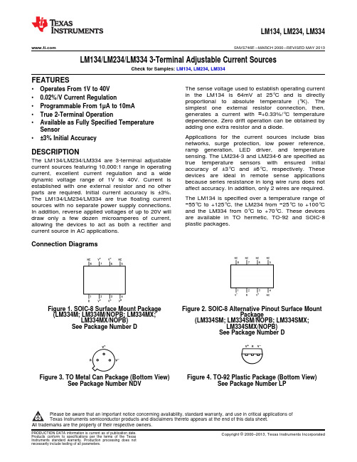
Absolute Maximum Ratings(1)(2)
V+ to V− Forward Voltage
V+ to V− Reverse Voltage R Pin to V− Voltage Set Current Power Dissipation ESD Susceptibility(3) Operating Temperature Range(4)
LM134, LM234, LM334
SNVS746E – MARCH 2000 – REVISED MAY 2013
Electrical Characteristics(1)
Parameter
Conditions
Set Current Error, V+=2.5V(2)
Ratio of Set Current to Bias Current
1mA < ISET ≤ 5mA
Temperature Dependence of Set Current(3) Effective Shunt Capacitance
(LM334SM; LM334SM/NOPB; LM334SMX; LM334SMX/NOPB)
See Petal Can Package (Bottom View) See Package Number NDV
Figure 4. TO-92 Plastic Package (Bottom View) See Package Number LP
AT3341 BDS GPS 双模授时板 产品手册说明书

BDS/GPS 双模接收机模块AT3341BDS/GPS 双模授产品手册版本:2016.01双模授时板AT3341目录一、功能描述 (3)1.1概述 (3)1.2关键特性 (3)二、技术描述 (4)2.1外观尺寸 (4)2.2硬件接口定义 (5)2.3电气参数 (6)2.4技术规范 (7)2.5模块使用注意事项 (9)2.6 PPS信号说明 (10)三、用户接口与协议 (12)3.1字符定义 (12)3.2输入/输出语句说明 (15)联系方式: (25)BDS/GPS双模授时板AT3341一、功能描述1.1概述AT3341是高授时精度的BDS/GPS双模接收机板卡,支持GPS和BDS的单系统授时定位和双系统联合授时定位。
其中的射频前端芯片和基带芯片全部为本公司独立研发,拥有自主知识产权。
AT3341包含32个跟踪通道,可以同时接收所有的GPS和BDS可见卫星。
AT3341可以直接替换国外授时板,主要接口信号Pin-Pin兼容,安装孔一致。
1.2关键特性授时精度:20ns支持BDS、GPS的单系统定位和双系统联合定位工作电流:62mA内置天线短路保护功能内置天线检测功能天线短路电流:50mA@(3.00V~5.00V)天线开路电流:5mA@(3.00V~5.00V)二、技术描述2.1外观尺寸尺寸:66mm×32mm×8.5mm2.2硬件接口定义其中串口为TTL电平、波特率可调。
波特率可选项为:4800bps、9600bps、19200bps、38400bps、115200bps,默认值为9600bps。
传输协议:1位起始位、8位数据位、1位停止位、无校验。
数据协议:见第三部分。
PPS特性:LVCMOS电平(3.3V)脉宽默认为100ms(占空比10%)。
2.3电气参数极限参数运行条件2.4技术规范用户采购时在采购信息表选择波特率予以定制示例:BDS/GPS双模授时板AT3341 2.5模块使用注意事项为了充分发挥AT3341的优良性能,用户在使用本模块时需要注意以下几点:●采用低纹波的LDO电源,将纹波控制在50mVpp以内。
平衡放大器的优点
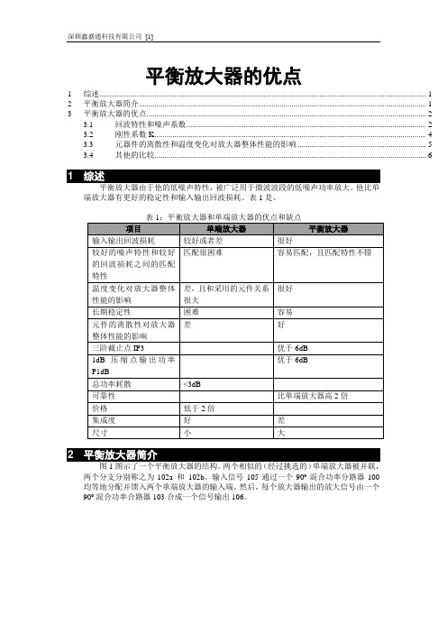
平衡放大器的优点1 综述 (1)2 平衡放大器简介 (1)3 平衡放大器的优点 (2)3.1 回波特性和噪声系数 (2)3.2 刚性系数K (4)3.3 元器件的离散性和温度变化对放大器整体性能的影响 (5)3.4 其他的比较 (6)1平衡放大器由于他的低噪声特性,被广泛用于微波波段的低噪声功率放大。
他比单端放大器有更好的稳定性和输入输出回波损耗。
表1是。
2图1图示了一个平衡放大器的结构。
两个相似的(经过挑选的)单端放大器被并联,两个分支分别称之为102a 和102b。
输入信号105通过一个90º混合功率分路器100均等地分配并馈入两个单端放大器的输入端。
然后,每个放大器输出的放大信号由一个90º混合功率合路器103合成一个信号输出106。
图1:一个平衡放大器的结构图3 平衡放大器的优点举一个例子:一个单端放大器和平衡放大器(他们都使用NE334S01砷化镓场效应管)在3.2 ~3.8 GHz频段的。
其中平衡放大器在每一个分支上使用一个单端放大器。
3.1 回波特性和噪声系数图2画出了一个单端低噪声放大器的原理图,PCB的材料是RO4003,厚度20mil,½ 盎司铜箔。
图2:使用NE334S01砷化镓场效应管的单端低噪声放大器的原理图图3图示了NE334S01砷化镓场效应管具有良好的噪声阻抗。
在这个图中,在3.4 GHz最佳的噪声源阻抗被定位在A点,在史密斯图中,A点远离50欧姆匹配点的中心。
换句话说,如果想得到最低的噪声系数,那回波损耗将很差。
如果设计一个在回波损耗上比较好的放大器,那大约会增加0.5dB的噪声系数。
可以从图3的等效噪声圆NCI 看到。
每个NCI圆表示增加0.25 dB的噪声系数。
在频率3.4GHZ时NE334S01有一个最佳的噪声系数0.35 dB。
图4:NE334S01 FET适宜的噪声阻抗图4图示了单端放大器的测试性能。
为了有0.35 dB的噪声系数,输入回波损耗就低于2 dB图4:使用NE334S01砷化镓场效应管的单端放大器的测试性能图5图示了由2个单端放大器组成的平衡放大器。
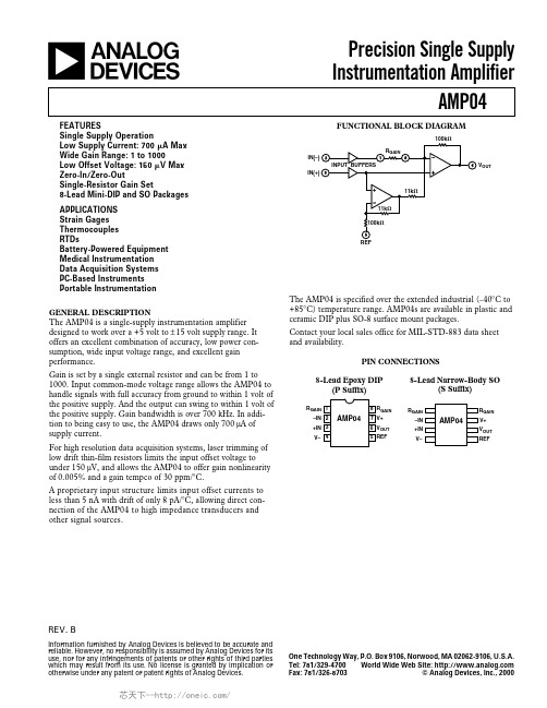
AMP04FSZ,AMP04FPZ,AMP04EPZ,AMP04FSZ-RL,AMP04FSZ-R7,AMP04FS-REEL7,AMP04ESZ-R7, 规格书,Datasheet 资料
One Technology Way, P.O. Box 9106, Norwood, MA 02062-9106, U.S.A.
Tel: 781/329-4700 World Wide Web Site:
Fax: 781/326-8703
© Analog Devices, Inc., 2000
For high resolution data acquisition systems, laser trimming of low drift thin-film resistors limits the input offset voltage to under 150 µV, and allows the AMP04 to offer gain nonlinearity of 0.005% and a gain tempco of 30 ppm/°C.
1000 1 0.005 0.015 0.025 30
0.75 %
1.0 %
0.75
%
1000 V/V
%
%
%
50
ppm/°C
OUTPUT Output Voltage Swing High
Output Voltage Swing Low Output Current Limit
VOH
RL = 2 kΩ
Contact your local sales office for MIL-STD-883 data sheet and availability.
PIN CONNECTIONS
8-Lead Epoxy DIP (P Suffix)
8-Lead Narrow-Body SO (S Suffix)
25
SN74ALS00AN3中文资料

PACKAGING INFORMATIONOrderable Device Status (1)Package Type Package Drawing Pins Package Qty Eco Plan (2)Lead/Ball FinishMSL Peak Temp (3)5962-86833012A ACTIVE LCCC FK 201None Call TI Level-NC-NC-NC 5962-8683301DA ACTIVE CFP W 141None Call TI Level-NC-NC-NC JM38510/37001B2A ACTIVE LCCC FK 201None Call TI Level-NC-NC-NC JM38510/37001BCA ACTIVE CDIP J 141None Call TI Level-NC-NC-NC SN54ALS00AJ ACTIVE CDIP J 141None Call TI Level-NC-NC-NC SN54AS00J ACTIVE CDIP J 141None Call TI Level-NC-NC-NC SN74ALS00AD ACTIVE SOIC D 1450Pb-Free (RoHS)CU NIPDAU Level-2-260C-1YEAR/Level-1-235C-UNLIM SN74ALS00ADBR ACTIVE SSOP DB 142000Pb-Free (RoHS)CU NIPDAU Level-2-260C-1YEAR/Level-1-235C-UNLIM SN74ALS00ADR ACTIVE SOIC D 142500Pb-Free (RoHS)CU NIPDAU Level-2-260C-1YEAR/Level-1-235C-UNLIM SN74ALS00AN ACTIVE PDIP N 1425Pb-Free (RoHS)CU NIPDAU Level-NC-NC-NC SN74ALS00AN3OBSOLETE PDIP N 14None Call TI Call TISN74ALS00ANSR ACTIVE SO NS 142000Pb-Free (RoHS)CU NIPDAU Level-2-260C-1YEAR/Level-1-235C-UNLIM SN74AS00D ACTIVE SOIC D 1450Pb-Free (RoHS)CU NIPDAU Level-2-260C-1YEAR/Level-1-235C-UNLIM SN74AS00DR ACTIVE SOIC D 142500Pb-Free (RoHS)CU NIPDAU Level-2-260C-1YEAR/Level-1-235C-UNLIM SN74AS00N ACTIVE PDIP N 1425Pb-Free (RoHS)CU NIPDAU Level-NC-NC-NC SN74AS00NSR ACTIVE SO NS 142000Pb-Free (RoHS)CU NIPDAU Level-2-260C-1YEAR/Level-1-235C-UNLIM SNJ54ALS00AFK ACTIVE LCCC FK 201None Call TI Level-NC-NC-NC SNJ54ALS00AJ ACTIVE CDIP J 141None Call TI Level-NC-NC-NC SNJ54ALS00AW ACTIVE CFP W 141None Call TI Level-NC-NC-NC SNJ54AS00FK ACTIVE LCCC FK 201None Call TI Level-NC-NC-NC SNJ54AS00JACTIVECDIPJ141NoneCall TILevel-NC-NC-NC(1)The marketing status values are defined as follows:ACTIVE:Product device recommended for new designs.LIFEBUY:TI has announced that the device will be discontinued,and a lifetime-buy period is in effect.NRND:Not recommended for new designs.Device is in production to support existing customers,but TI does not recommend using this part in a new design.PREVIEW:Device has been announced but is not in production.Samples may or may not be available.OBSOLETE:TI has discontinued the production of the device.(2)Eco Plan -May not be currently available -please check /productcontent for the latest availability information and additional product content details.None:Not yet available Lead (Pb-Free).Pb-Free (RoHS):TI's terms "Lead-Free"or "Pb-Free"mean semiconductor products that are compatible with the current RoHS requirements for all 6substances,including the requirement that lead not exceed 0.1%by weight in homogeneous materials.Where designed to be soldered at high temperatures,TI Pb-Free products are suitable for use in specified lead-free processes.Green (RoHS &no Sb/Br):TI defines "Green"to mean "Pb-Free"and in addition,uses package materials that do not contain halogens,including bromine (Br)or antimony (Sb)above 0.1%of total product weight.(3)MSL,Peak Temp.--The Moisture Sensitivity Level rating according to the JEDECindustry standard classifications,and peak solder temperature.28-Feb-2005Important Information and Disclaimer:The information provided on this page represents TI's knowledge and belief as of the date that it is provided.TI bases its knowledge and belief on information provided by third parties,and makes no representation or warranty as to the accuracy of such information.Efforts are underway to better integrate information from third parties.TI has taken and continues to take reasonable steps to provide representative and accurate information but may not have conducted destructive testing or chemical analysis on incoming materials and chemicals.TI and TI suppliers consider certain information to be proprietary,and thus CAS numbers and other limited information may not be available for release.In no event shall TI's liability arising out of such information exceed the total purchase price of the TI part(s)at issue in this document sold by TI to Customer on an annualbasis.28-Feb-2005IMPORTANT NOTICETexas Instruments Incorporated and its subsidiaries (TI) reserve the right to make corrections, modifications, enhancements, improvements, and other changes to its products and services at any time and to discontinue any product or service without notice. Customers should obtain the latest relevant information before placing orders and should verify that such information is current and complete. All products are sold subject to TI’s terms and conditions of sale supplied at the time of order acknowledgment.TI warrants performance of its hardware products to the specifications applicable at the time of sale in accordance with TI’s standard warranty. T esting and other quality control techniques are used to the extent TI deems necessary to support this warranty. Except where mandated by government requirements, testing of all parameters of each product is not necessarily performed.TI assumes no liability for applications assistance or customer product design. Customers are responsible for their products and applications using TI components. T o minimize the risks associated with customer products and applications, customers should provide adequate design and operating safeguards.TI does not warrant or represent that any license, either express or implied, is granted under any TI patent right, copyright, mask work right, or other TI intellectual property right relating to any combination, machine, or process in which TI products or services are used. Information published by TI regarding third-party products or services does not constitute a license from TI to use such products or services or a warranty or endorsement thereof. Use of such information may require a license from a third party under the patents or other intellectual property of the third party, or a license from TI under the patents or other intellectual property of TI.Reproduction of information in TI data books or data sheets is permissible only if reproduction is without alteration and is accompanied by all associated warranties, conditions, limitations, and notices. Reproduction of this information with alteration is an unfair and deceptive business practice. TI is not responsible or liable for such altered documentation.Resale of TI products or services with statements different from or beyond the parameters stated by TI for that product or service voids all express and any implied warranties for the associated TI product or service and is an unfair and deceptive business practice. TI is not responsible or liable for any such statements. Following are URLs where you can obtain information on other Texas Instruments products and application solutions:Products ApplicationsAmplifiers Audio /audioData Converters Automotive /automotiveDSP Broadband /broadbandInterface Digital Control /digitalcontrolLogic Military /militaryPower Mgmt Optical Networking /opticalnetwork Microcontrollers Security /securityTelephony /telephonyVideo & Imaging /videoWireless /wirelessMailing Address:Texas InstrumentsPost Office Box 655303 Dallas, Texas 75265Copyright 2005, Texas Instruments Incorporated。
TC334_中文手册_F1V2.0

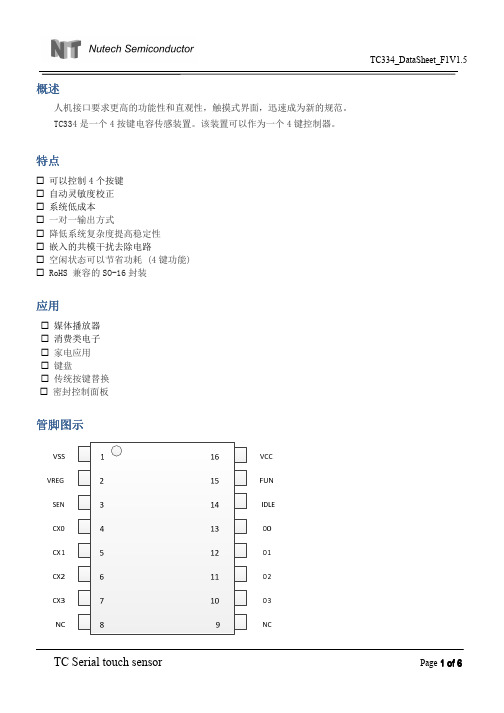
TC334中文手册目录1.概述 (1)2.特点 (1)3.应用 (2)4.管脚图示 (2)5.管脚描述 (2)6.芯片功能 (3)6.1初始化时间 (3)6.2灵敏度 (3)6.3自校正 (4)6.4触摸反应时间 (4)6.5输出逻辑 (4)6.6睡眠模式 (4)7.应用原理图 (4)8.模拟电压输出 (4)9.PCB版图注意事项 (5)10.额定值 (5)11.电气特性 (6)12.ESD特性 (6)13.封装尺寸图(SO-16) (6)1.概述人机接口要求更高的功能性和直观性,触摸式界面,迅速成为新的规范。
TC334是一个4按键电容传感装置。
该装置可以作为一个4键控制器。
2.特点☐可以控制4个按键☐自动灵敏度校正☐系统低成本☐一对一输出方式☐降低系统复杂度提高稳定性☐嵌入的共模干扰去除电路☐空闲状态可以节省功耗(4键功能)☐RoHS兼容的SO-16封装3.应用☐媒体播放器☐消费类电子☐家电应用☐键盘☐传统按键替换☐密封控制面板4.管脚图示5.管脚描述引脚名称输入/输出描述1VSS电源负极地参考2VREG模拟输出内部参考源输出3SEN模拟输入输出灵敏度电容4CX0模拟输入输出感应输入05CX1模拟输入输出感应输入16CX2模拟输入输出感应输入27CX3模拟输入输出感应输入310O3输出按键3输出11O2输出按键2输出12O1输出按键1输出13O0输出按键0输出14IDLE输入空闲使能端口15FUN输入功能选择端口16VCC电源正极供电电压输入SEN此管脚电容大小为15pf~100pf,电容越小灵敏度越高。
VREG内部参考源输出,接4.7nf电容。
CX0~CX3感应管脚,串联电阻是3KΩ。
O0~O3CX0~CX3的相应输出端口,有高阻和低电平两种状态。
IDLE设置为高电平时,如果75秒无按键,芯片进入空闲状态,否则会一直保持正常工作状态。
FUN接VSS6.芯片功能6.1初始化时间上电复位后,芯片需要300ms进行初始化,计算感应管脚的环境电容,然后才能正常工作。
TC334_中文手册_F1V1.5
TC Serial touch sensor
Dimensions In Inches Page 5 of 6
TC334_DataSheet_F1V1.5
Min
Nom
Max
Min
Nom
Max
A
1.30
1.50
1.70
0.051
0.059
0.067
A1
0.06
0.16
0.26
0.002
0.006
0.010
PCB 版图注意事项
1. VCC 和 VSS 电源线要单独走线,不能和其它芯片(单片机和 LCD 驱动芯片等)共用电源走线。以免 使其它芯片的干扰信号通过电源线引到触摸芯片。
2. CP,CVREG,CSEN 三个电容必须靠近芯片放置。感应线上串联的 CX0~CX3 电阻,靠近芯片放置为宜。 3. 尽量大的铺地面积,可以提高抗干扰性。 4. 感应连线和感应焊盘优先布局。芯片靠近感应焊盘放置,感应连线直接引到感应焊盘(或弹簧焊 盘),不同按键的感应连线不需要长度一致。感应连线线宽尽量小。感应连线周围不能走其他电源线和信号 线。如果实在不能避免,其他走线要垂直跨过感应连线。感应焊盘之间至少留 5mm 间距,感应焊盘和铺地 之间距离大于 1.5mm。
额定值 *
工作温度 存储温度 电源电压 管脚最大电流 管脚电压 * 注意 超出额定值可能会导致芯片永久损坏
-40 ~ +85ºC -50 ~ +150ºC -0.3 ~ +6.5V ±20mA -0.3V ~ (Vcc+ 0.3) Volts
电气特性
TA = 25℃ 特性 工作电压 电流消耗
符号 Vcc Idd
O1 高阻 低电平 高阻 高阻 高阻
Renesas(三菱) M54133 Datasheet漏电芯片最新资料
Old Company Name in Catalogs and Other Documents
On April 1st, 2010, NEC Electronics Corporation merged with Renesas Technology Corporation, and Renesas Electronics Corporation took over all the business of both companies. Therefore, although the old company name remains in this document, it is a valid Renesas Electronics document. We appreciate your understanding.
Renesas Electronics website:
April 1st, 2010 Renesas Electronics Corporation
Issued by: Renesas Electronics Corporation () Send any inquiries to /inquiry.
Notice
1. All information included in this document is current as of the date this document is issued. Such information, however, is subject to change without any prior notice. Before purchasing or using any Renesas Electronics products listed
IRS20124S中文资料
IRS20124S中文资料D IGIT AL A UDIO D RIVER WITH D ISCRETE D EAD -TIME AND P ROTECTIONProduct SummaryV SUPPL Y 200V max.I O +/-1A / 1.2A typ.Selectable Dead Time15/25/35/45ns typ.Prop Delay Time 70ns typ.Bi-directional Over Current SensingFeatures200V high voltage ratings deliver up to 1000Woutput power in Class D audio amplifier applicationsIntegrated dead-time generation and bi-directional over current sensing simplify designProgrammable compensated preset dead-time for improved THD performances over temperature ?High noise immunity Shutdown function protects devices from overload conditionsIRS20124S(PbF)SymbolDefinitionMin.Max.UnitsV B High side floating supply voltage -0.3220V V s High side floating supply voltage VB-20VB+0.3V V HO High side floating output voltage Vs-0.3VB+0.3V V CC Low side fixed supply voltage -0.320V V LO Low side output voltage -0.3Vcc+0.3V V INInput voltage-0.3Vcc+0.3V V OC OC pin input voltage-0.3Vcc+0.3V V OCSET1 OCSET1 pin input voltage -0.3Vcc+0.3V V OCSET2OCSET2 pin input voltage-0.3Vcc+0.3V dVs/dt Allowable Vs voltage slew rate-50V/ns Pd Maximum power dissipation- 1.25W Rth JA Thermal resistance, Junction to ambient -100°C/W T J Junctio n Temperature -150°C T S Storage Temperature-55150°CT LLead temperature (Soldering, 10 seconds)-300°CAbsolute Maximum RatingsAbsolute maximum ratings indicate sustained limits beyond which damage to the device may occur. All voltage parameters are absolute voltages referenced to COM. All currents are defined positive into any lead. The thermal resistance and power dissipation ratings are measured under board mounted and still air conditions.DescriptionThe IRS20124S is a high voltage, high speed power MOSFET driver with internal dead-time and shutdown functions specially designed for Class D audio amplifier applications.The internal dead time generation block provides accurate gate switch timing and enables tight dead-time settings for better THD performances.In order to maximize other audio performance characteristics,all switching times are designed for immunity from external disturbances such as VCC perturbation and incoming switching noise on the DT pin. Logic inputs are compatible with LSTTL output or standard CMOS down to 3.0V without speed degradation. The output drivers feature high current buffers capable of sourcing 1.0A and sinking 1.2A. Internal delays are optimized to achieve minimal dead-time variations. Proprietary HVIC and latch immune CMOS technologies guarantee operation down to Vs= –4V, providing outstanding capabilities of latch and surge immunities with rugged monolithic construction.Recommended Operating ConditionsFor Proper operation, the device should be used within the recommended conditions. The Vs and COM offset ratings are tested with all supplies biased at 15V differential.Symbol Definition Min.Max.Units V B High side floating supply absolute voltage Vs+10Vs+18V V S High side floating supply offset voltage Note 1200VV V HO High side floating output voltage Vs VB V CC Low side fixed supply voltage1018V V LO Low side output voltage0VCC V V IN Logic input voltage0VCC V V OC OC pin input voltage0VCC V V OCSET1OCSET1 pin input voltage0VCC V V OCSET2OCSET2 pin input voltage0VCC V T A Ambient Temperature-40125°CDynamic Electrical CharacteristicsV BIAS (V CC, V BS) = 15V, C L = 1nF and T A = 25°C unless otherwise specified. Figure 2 shows the timing definitions.IRS20124S(PbF)Lead DefinitionsSymbol DescriptionVCC Low side logic Supply voltage VB High side floating supply HO High side outputVS High side floating supply returnINLogic input for high and low side gate driver outputs (HO and LO), in phase with HODT/SD Input for programmable dead-time, referenced to COM. Shutdown LO and HO when tied to COM COM Low side supply returnLO Low side outputOC Over current output (negative logic)OC SET1Input for setting negative over current threshold OC SET2Input for setting positive over current thresholdIRS20124S(PbF)VBHOVSO O C S E T O C S E T VccLOCOM50%50%t off(L)t on(L)90%10%90%10%DT HO-LOt off(H)INHOLOt on(H)DT LO-HO DT/SDHO LOV SDT SD90%Figure 1. Switching Time Waveform Definitions Figure 2. Shutdown Waveform Definitions IRS20124S(PbF)toc filt HIGHVSOCV soct COMCOMtwocVSOCV Soc+tdocCOM COMLOV Soc-15V Vsoc+Vsoc-OCVsoc+Vsoc-COM VSOCFigure 5. OC Waveform DefinitionsFigure 3. OC Input FilterTime Definitions IRS20124S(PbF)IRS20124S(PbF)2.0()2()IRS20124S(PbF)2430()()IRS20124S(PbF)10()10()IRS20124S(PbF)。
松下交流伺服说明书A4使用手册+中文
C~F 型:内置制动电阻(也可再外接制动电阻)。
内置
通过参数选择以下 7 种模式:①位置控制;②速度控制;③转矩控制;④位 置/速度控制;⑤位置/转矩控制;⑥速度/转矩控制;⑦全闭环控制
Minas A4 系列驱动器技术资料选编
控制输入
控制输出
最大指令脉冲频率
位 脉冲
置 输入
控
输入脉冲串形式 指令脉冲分倍频 (电子齿轮)
可设定范围:(1~10000)× 20~17 1~10000
对指令脉冲可选择初级延时滤波器或者 FIR 滤波器 可在 CCW、CW 两个方向分别设置转矩限制(3V/额定转矩)
可用 可用 可用 ⑤CW 方向行程禁止,⑥CCW 方向行程禁止,⑦内部速度选择 1, ⑧内部速度选择 2,⑨零速箝位 ⑥速度到达 可输入模拟量速度指令,其比例和方向用参数可调(默认值:6V/额定转速) 可在 CCW、CW 两个方向分别设置转矩限制(3V/额定转矩) 通过控制输入点可选 4 段内部速度 可分别设置 0~10s/1000rpm 的加速、减速时间;S 形加减速时间也可设置 可通过零速箝位输入使得内部速度保持为 0 可用 可用 ⑤CW 方向行程禁止,⑥CCW 方向行程禁止,⑦零速箝位 ⑥速度到达
4 点输出: 编码器信号(A/B/Z 相)或外部反馈装置信号(EXA/EXB/EXZ 相)输出差分 信号;Z 相或 EXZ 相也可以输出集电极开路信号。
主机 1:1 通讯 主机 1:n 通讯,n≤15
①5 个按键(
、 、 、 、 );②6 位 LED 显示
A、B 型驱动器:没有内置制动电阻(只可外接);
环境温度
主电源电缆
MADDCT1105 单相 100V 10A 5A
接地电缆
伺服电机基础
系统的构成
伺服驱动器 伺服电机
执行机构
人机界面 上位机
伺服系统的介绍
按进给伺服系统分类;控制系统的构成可分为: 开环回路控制 半闭环回路控制 全闭环回路控制
控制系统的构成1/3
◎开环回路控制OPEN LOOP 由控制器输出指令讯号;用来驱动马达依指令值位移并且 停止在所指定的位置;
马达
传动机构
注塑机
MSMA 50W 2軸
单挤空自动充填结扎机
灌装机
本机广泛适用于白酒 黄酒 酱油 醋 调味品 植 物油 糖浆 矿泉水等可食性液体以及农药化工 类液体的灌装
雕 刻 机
木工雕刻机
等离子切割机
激光雕刻机
喷绘机
纸箱纵切机
高速电子轴无轴凹版印刷机
多梳经编机
数控拉舍尔经编机
RFB全幅衬纬型缝编机
则机械位置解析度Resolution =PB 1/R/PE 4 =0 002mm <机械定位精度±0 05mm
收益
高精度; 大调速范围; 快速响应提高设备的运行速度;
我们可以认为: 伺服技术应用使得机械设备的整体性能得到 了大幅度的提高;
交流伺服电机与变频电机的区别
低频启动力矩 速度范围
控制方式
※依据不同的控制系统之需求;在驱动 器中有三种控制模式可供选择 扭矩控制
速度控制
位置控制
扭矩控制
扭矩指令输入范围
0 ~ ±10V正电压>CCW扭力 0 ~ 额定扭力
依据输入电压的大小 达到 控制马达输出扭力的目的;
扭矩控制
扭矩控制方式是通过外部模拟量的输入或直接的地址的赋值 来设定电机轴对外的输出转矩的大小;具体表现为 例如10V 对应5Nm的话;当外部模拟量设定为5V时电机轴输出为2 5Nm:如果电机轴负载低于2 5Nm时电机正转;外部负载等于2 5Nm时电机不 转;大于2 5Nm时电机反转通常在有重力负载 情况下产生; 可以通过即时的改变模拟量的设定来改变设定 的力矩大小;也可通过通讯方式改变对应的地址的 数值来实 现; 应用主要在对材质的受力有严格要求的缠绕和放卷的装置中; 例如绕线装置或拉光纤设备;转矩的设定要根据缠绕的半径的 变化随时更改以确保材质的受力不会随着缠绕半径的变化而 改变;
【word】人肌肌酸激酶胍变性时的失活与构象变化的比较研究

人肌肌酸激酶胍变性时的失活与构象变化的比较研究0/∈82/第s卷第4期生物物理1992年12月ACTABIOPHYSICASINICA8f.V01.8No.4人肌肌酸激酶胍变性时的失活与构象变化的比较研究.兰—塑~堡【希成周海梦(祷华大学生物科学与技术系,北京lO00)(一p辑院生物物理所生物大分子国家重点验空-北京100101)摘要07/应用二阶导数光谱,紫外差吸收光谱和荧光光谱等监测手段,研完了人肌肌酸激酶在盐酸胍溶液中的构象变化二阶导数光谱结果表明,若以6M盐酸胍中肌酸激酶酪氨酸残基的暴露程度为100面,旦天然酶酪氨酸残基的暴露程度只有2面.而紫外差吸收光谱和荧光光谱的变化与兔肌肌醢墩酶的结果相似.比较不同胍浓度下人肌肌酸澈酶的失活与构象变化,表明酶的失活先于构象变化.同时还铷定了不同浓度弧溶液中人肌酶的失话与构象变化的速度常数.结果表明以几种方法测定的构象变化均为单相的一瓤过程,而酶的失活却呈现了出快漫两相蛆成的一级反应过程.比较同浓度胍溶液中的失活速度与构象变化速度,发现酶戋活的饶相厦应速度常数比构象变化的速度常数犬1—2个数量级,馒相速度常数与扮象变化速度常数相近.上述结果进一步支持了酶的活性部位构象关键词t人肌肌酸激酶,!兰!塾堡,活性前言f,Ij几酸激酶(A TPtCreatineN-phosphotransferase,EC2.7.3.2)是催化A TP 与肌酸之间转磷酸化反应的重要激酶.近年来许多作者研究了兔肌肌酸激酶在变性剂存在下失活与构象变化,得到了有关酶分子活性部位构象柔性的重要理论【I】,同时还对伸展的酶分子在折叠过程中的复活与构象变化进行了深入的研究,为蛋白质分子的体蚪折叠取得了一些重要的信息[e-t】.本文报导了二阶导数光谱,紫外差吸收光谱剩荧光发射光谱为监测手段,研究人肌肌酸激酶在胍溶液中的构象变化,并与兔肌肌酸澈酶比较,结果表明两者的酪氨酸残基的微环境有显着的差异,但色氢酸残基的微环境很相似.此外比较了各种不同浓度胍溶液中酶的失活程度和构象变化程度,发现在低浓度胍溶液中,构象尚未发生明显变化,丽酶的活力几乎全部丧失.同时还比较了同浓度胍溶液中失话与l构象变牝的速度常数,发现失活速度远快于构象变化速度,得到了酶活性部位构象上柔性的进一步证据.材料与方法人肌肌酸激酶从人骨骼肌中按改造了的Ritter.法制备.酶制品经聚丙烯酰胺凝腔电国家自然社学基金资肋顷E生物物理1992监泳及sDs一凝胶电泳鉴定为一条带.酶的比活力为216/Imol/mg?min. 肌酸为 E.Merck公司产品,A TP为Fluka产品,盐酸胍为UnltedStaLeSBiochemicaICorP产品,uV纯;N乙酰~L色氨酸,N一乙酰一L一酪氨酸均为Sigma 产,其余试剂均为国产分析纯试剂.酶浓度是根据280rim处吸光值按消光系数E=8.8计算….酶活力的测定用pH一比色法….二阶导数光谱在Kontronuvon一860分光光度计上进行,扫描速度为100nm/raln.在蛋白质紫外吸收对波的二阶导数谱图中,280--300nm的吸收峰主要由Tyr釉p产生.比值r=(Azs~一A28)/(虬一Azs)随Trp环境变化很小,但对Tyr环境t 很敏感,此可用r来衡最Tyr所处环境变化”;=(一r.)/(r.一r.)oⅡ为Tyr暴露程度,rl是要测量的蛋白质的r值}r是假设酪氨酸完全暴露时的r值,本文中为6M盐酸胍中变性1小时舶人肌肌酸激酶的ri}r.是由模型化台物得到的参考值,意义是当同样比例的Tyr和Trp处于蛋白质内部时的r值,本文中为相同比例的N乙酰一L一色氨酸与N一乙酰一L一酪氨酸溶于乙二醇中的r值.紫外差吸收光谱也在KonIronUVion一860分光光度计上进行.荧光发射光谱的测定是在HITACHI-850型荧光分光光度计上进行的.激发波长为280nm,扫描范围为3O0nm一420ni32o本文所有测定均在2℃下进行.缓冲液体系采用pH9.0,0.1NNaOH—Glyeine缓冲液.酶的失活动力学过程是采用在盐酸胍存在下连续监测失活的方法测定的.结果.一,人肌肌畦激奠在腻溶液中的=阶导散光谨将人肌肌酸激酶在各种不同浓度的盐酸胍溶液中变性1小时,然后分别测定其二阶导数光谱.从图1可见,人叽肌酸澈酶在胍变性时的:=阶导数光谱在283,287,291,295nm有四个吸收峰.随着盐酸胍浓度增加,Z83nm,287nm吸收峰值都明显增高,而291,295nin处峰值变化不大.所,由材料与方法中所述计算酪氨酸暴露程度可知,随着胍浓度增大,酪氨酸暴露程度增大.如果以6M胍中酪氲酸暴露程度为100,则0,0.3,0.5,1.0,2.0,3.0M胍人肌肌酸激酶酪氨酸暴嚣程度分别为2,14.5,24.1,66.1, 90.6%,97.4.二,人肌肌酸激酶在胍溶液中的紫外整吸收光谱和荧光发射光谱将人肌肌酸酶在各种:间敞度盐酸胍溶液中变性1小时后,分别扫描其紫外差吸收光谱,其结果裘明在1M以F肋低浓度腼溶液中酶的变性差光谱中,只出现281和287nm两个负差吸收峰.随着胍浓度的升高负差吸收峰增高,在2M胍溶液中在292nm处出现微弱的肩峰,j3M胍涪澉{JlJ现驯显的肩峰,并且各蜂均达到最大负吸收值a人肌肌酸激酶在胍溶激中变性l小倒后荧光发射光谱表明天然酶发射蜂位置在334nm处.随着胍浓度加大,发射峰峰位发生明显红移,直到胍浓度为3M时,红移达到最大值,郎355nm处.上述结果与兔肌酶栩似,三,在盐酸腻溶液中酶的活力变化与构象变化程度的比较第4期人叽肌酸墩酶肛变性时的失括与桕象变化的比较研究677在与上述研究胍溶液中拘象变化的同样实驻条件下,测定酶在各种不同浓度的胍溶液中变忭1小时后的剩余活力.胍浓度与剩余活力之间的父系表示于网2中.将在符种不同浓度的胍溶澉r}1’以=:阶导数光谱的”值,287nra紫外差吸收恤和菠光发射光谱红移值的变化为标志的构象变化程度也表示于图2中.从图2rf|可见酶失活先于酶的构象变化,Fig.1SeonddeIivativespectraofhumaⅡrreatiekin&5edenaturatedinguanidine50—1tlti0Ⅱsofdifferentconcentr-tions.Theenzymeconcentratlonw&s15.7Mdissev]edin0.1MN.OH—glycinebuffer,pH9.0.The叩一eetrawerereededafter1hourincubatio11at25℃.TheorfinaIeoneentratio[isofguanidinewere0.0,0.3,0.5,1.0,2.0,3.0M,respe—etirely,forcurves1-6.同时可见在低浓度胍溶液中,例如O.5M时,酶活力已经丧失90以上,而以三种方法监测构象的变化尚在30以下.这表明在低浓度胍溶液中酶的失活先于酶的构象变化.Fig.21nactivati0ⅡanddeⅡ-turatieofhu越-ncr—e-tinekinasetitratedbyguanidines01ution.Theenzymes01utio11waBineubatedwithguaⅡidineofdifferentc0licentrationsforlh0ur4ftertitration£Ddeterrainetherem&inactivity(▲),theUyab—sorbance(0),theexposureofTyrgroups(●), andtheredshiftoffluorescencespectra(△),Fi—naIconcentratl0118ofenzymewer82Mforacti—ityass-y,12.1MforUV-bBorbane0,1.2Mforfluoresc0nc0emissionand15.7Mfor$econd derivativeabsorbance.四,人肌肌馥激酶在各种不同浓度的凰溶液中的构象变化速度以二阶导数光潜监测的Tyr残基暴露为林忐的构象变化速度,结果表示于图3中.圉3a为随时间的变化过程,围3b为半对数ff.以紫外差吸收光谱和荧光发射光谱监测Trp和Tyr残基暴露为怀志的构象变化速度,其结果分别表示予图4和图中. 上述三种方法监测得到的构象变化过程均为单相的一级反应过程,它们的变化速度常数均列表1中.五,人肌肌馥激醴在盐馥凰溶液中的失活速度将人肌肌酸激酶加入台有胍的底物体系叶』,而后连续监测产物随时问的变化(监测A』竹变化)._刑嬲实验表明,在本实验测定范同内,不会因反应过程中底物消耗和产物增加而影响反应初迪度.因此一将产物曲线作一阶导函数,而得到酶的失活曲线(以天然酶~嚣一毖日0生物物Tlmc(mlnTimerainFig.4RatesofUV absorhaneechangesofhumancreatinekinaseinguanidinesol u—tionsofdiff~rentconcentrations.(i)ChangeBinabsorbanceat287nmerereco —rdedafterl2.7Meuzyme珀ixedwithguanidineat25℃.ThefinalconcentrationsofguanidiⅡewere0.3,0.5,1.0,2.0,3.OM,respectively,forcucve1—5.(b)Co—rre3pondingemilogarlthmieplotofcurve3inFig.4atodeterminethedenaturati onratec0113tant.,活力为lo0)?将Jn—r}对时间作囤可求出失活速度常数,发现变化是_两相的,存在一个快相和一个慢鼾『.各种胍浓度下失活过程的两相速度常数k-和k 值列于表l中.从表1的结果可见随着浓度增大,构象变化加快rat{0n0fG…1djn(M)InHtt{v-tI…自LefS_.×10)KK_l…..___二ll二工=I_I.f:l:!::!——厂_T—■—]一¨2919.911.0g.33013052.9139从图4的结果可见,紫外差吸收光谱和荧光发射光谱随着胍浓度的变化趋势几乎一致,这是因为两种方法所监测的都是色氨酸租酪氨酸残基微环境变化,即监测部位相同.而二阶导数光谱监测的仅是酪氨酸残基的变化,因此与用上述两种方法监测的结果略有偏离.但是总的结果看,酶的失活先于均象变化.在低浓度胍溶液中(如0.5M 时),酶的活性已几乎丧失,而分子构象尚未发生严重破坏.然而与兔肌肌酸激酶的结果相比,人肌肌酸激酶构象的稳定性比兔肌酶差a以阶导数光谱,紫外差吸收光谱和荧光发射光谱三种手段监测到的酶在胍溶液中曲构象变化过程是单相的一级反匣过程,j!种方法所测得的反应速度常数基本一致.酶的失活过程却是由快,慢两棚组成的一级反过程.比较同浓度脏溶液中二者变化的速度常数,结果表叫,在lM以下低浓度胍溶液中,酶失活托快相反应速度常数比构象变化速度常数火1—2个数量级,而失活的慢相反应速度常数与构象变化速度常数相接近.在2M一3M的胍溶液变性时,失活速度大幅度加’陕,用常规动力学方法监测不到变化过程而此时枸象变化却还是以较慢的速度进行.上述结果表明酶盼陕相失活可能是由于活性部位构象的变化所引起的.上述结果进一步支持了酶的活性部位柯象柔性的学说r. 参考文献[1:Yao,Q.ztetal:Sol-sL口.,25B-1982,1188-1193[2]Y自0,Q.Zetal:Sci.SiD,25B-1982.1299-]302.[3:YeoQz.etI.Biochemlsti-23,1984.9~40-2744.¨.=._三~“蚰”咀h¨岫m¨h∞一吐哪盯一~“第4期人肌肌酸墩酶胍变性时的失活与构泉变化的比较研兜[8jrt]1O]l】]12]13jLjI1,C.H.et1:ChiⅡe5eScLnceBu1letiD,Ho12】1g89,1036-1040.Ts0uC.L.TrndsinBiohi4】Se;.Dces,11,l08a.425-429.候立向等,生_物1艺学与生物物理.15(5),1083.393—397Zh0,H.M.eⅡdT5.,C.L.B㈣eh1.Biophys.Acta896.1蛐0,a9—74Ritter.C.S.ClinChem.2T(11)tl081.1878—188T~ratt日DC.TheE…Y.(Ed?Boyr.PD),AcadPfe 日,NwY orkaiidLondon,8(1J73),383-453Raffae】,t1.,Biuhemi5ty.23,1884,1871-1875.Robtsrt,V.T.,T11eJ~urnalofBiologica1Chemi{tr,23,1988?17142—1149 Bulstei口,EA.eta1.:Photoohent.PhoL0hio1.18,19T3,263—279睢小之等:生物物理,7(3).1991,335—34O. ACOMPARISONOFCONFORMA TIONALCHANGESAND INACTIV A TIoNRA TESoFCREA TINEKINASE FRoMHUMANMUSCLEDURINGGUANIDINEDENA TURA TIoN LiYingftouLixiangWangXickengZhouHaimeng(Departmento/Bio[ogica[SciencesandBiolechnotogy,Tsinghua Uniuers?Befing,100084)(NationafLaboratoryo/Biomacromoteeutes,[nstitule0,Biophys(csp AeademiaSinica,Bef,fng,100101)ABSTRACTTheconformatlona1changesofcreatinekinasefromhumanmuzeleduffng denaturatlonbydifferentconcerttrationsofguanidinehydrochloridehavebeen studiedbysecondderivativepectra,fluoreseenceanduItlla’~rlMetdifferentia 1口ectroseopiemethods.Theresultsobtainedbysecondderivafivespectrashowed thatifthehiddentyrodneresiduesoftheeuzymein6Mguanidineareconsidered tobeexposedcompletely,only2%tyrosinegroupsofnativchumancreatine kinaseareexposedtohydrophllieenvironment?Thechangesoffluorescencean dUVdifferentia1slUectraarcthesafileasthoseofrabbitcreatinekinase. Rateconstantsofconformationalchangesandinactivationofhumancreatine kinaseduringdenaturationatthedifferentconcentrationsofguauidinehave heenalsodeter111ined.TheconformationalehangecoursesinthedifferentCO LIC—entrationsofguanidinehavebeentobefirstorderre~tctions.1lowever,inact—parisonofrdtesofinactivationandconforma —曲±!物物理tlona1changesshowclearlythattherateCOIlstuntSofthefastphasesofiila etlvationofthehumancreatlnekinaseare12ordersofmagnitudefasterthantherateCODstantsofconformationalchanges.whereasslowphaseconstantSal e vcrvclosetotherateCOilstantsofconformationalchangeS.AboveresultSfur thersupportthesuggestloaofthelocationoftheactlve5iteoftheeazyme inlimitedandflexihiemolecularregi0II.KeyWords:Creatlneklnasefrorahumannlusc]e,Guanidinedenaturation, Conformatlon,Activity.。
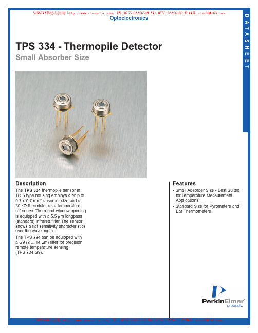
TPS 334 - Thermopile Detector 说明书
TPS 334 - Thermopile Detector Small Absorber Size D A T A S H E E TDescriptionThe TPS 334thermopile sensor in TO 5 type housing employs a chip of 0.7 x 0.7 mm2absorber size and a 30 kΩthermistor as a temperature reference.The round window opening is equipped with a 5.5 µm longpass (standard) infrared filter.The sensor shows a flat sensitivity characteristics over the wavelength.The TPS 334 can be equipped with a G9 (8 ...14 µm) filter for precision remote temperature sensing(TPS 334 G9).OptoelectronicsFeatures• Small Absorber Size - Best Suitedfor T emperature MeasurementApplications• Standard Size for Pyrometers andEar ThermometersSUNSTAR传感与控制/TEL:0755-********FAX:0755-********E-MAIL:************** SUNSTAR自动化/TEL:0755-********FAX:0755-********E-MAIL:**************TPS 334 - Thermopile Detector Small Absorber Siz e Page 2© 2003 PerkinElmer, Inc.All rights reserved.PerkinElmer, the PerkinElmer logo and the stylized “P”are trademarks of PerkinElmer, Inc.DS447-Rev A-0503*******************************************************************/optoelectronicsAll values are nominal;specifications subject to change without notice.North America:PerkinElmer Optoelectronics 16800 Trans-Canada HighwayKirkland, Quebec J7V 8P7 Canada Toll Free:(877) 734-OPTO (6786)Phone:+1-450-424-3300Fax:+1-450-424-3411Europe:PerkinElmer Optoelectronics Wenzel-Jaksch-Str.31D-65199 Wiesbaden, Germany Phone:+49-611-492-430Fax:+49-611-492-165Asia:PerkinElmer Optoelectronics 47 Ayer Rajah Crescent #06-12Singapore 139947Phone:+65-6770-4366Fax:+65-6775-1008Figure 5.Bottom ViewParameter Typical Units Condition Sensitive area 0.7 x 0.7mm 2absorbing area Window size 2.5mm diameterDC sensitivity 35V/W 500K BB 5 ...14µmResistance 75k ΩNoise 38nV/√Hz r.m.s.300K NEP 1.2nW/√Hz 500K BB 5 ...14µm D*0.6 x 108cm √Hz/W 500K BB 5 ...14µm TC of sensitivity 0.02%/K TC of resistance 0.02%/K Time constant 25ms Operating temperature -40 to 100°C non permanent Storage temperature -40 to 100°C non permanent Thermistor resistance30k Ω25°C beta3964K 25°C/100°C Field of view60°at 50% points Table 1.TPS 334Figure 1.Package DrawingFigure 4.Top View Package Dimension Figure 2.Figure 3.SUNSTAR传感与控制/TEL:0755-********FAX:0755-********E-MAIL:**************SUNSTAR自动化/TEL:0755-********FAX:0755-********E-MAIL:**************R i g h t f o r m o d i f i c a t i o n r e s e r v e d / W S /, 21.5.2001D A T A S HE E TThermopile Detector TPS 334Small absorber size best suited for temperature measurement applicationsStandard type for pyrometers and ear thermometersThe TPS 334 thermopile sensor in TO 5 type housing employs a chip of 0.7 x 0.7 mm 2 absorber size and a 30 k V thermistor as temperature reference.The round window opening is equipped with a 5.5 m m longpass (standard)inf rared f ilter. The sensor shows a f lat sensitivity characteristics over the wavelength.The TPS 334 can be equipped with a G9 (8..14 m m) filter for precision remotetemperature sensing (TPS 334 G9).R e l a t i v e s i g n a l o u t p u tFrequency in Hz-100-80-60-40-2002040608010020406080100TPS 334N o r m a l i z e d s i g n a l i n p e r c e n tAngle of incidence in degreesr e t e m a r a P la c i p y t st i n u no i t i d n o c a e r a e v i t i s n e S e z i s w o d n i W y t i v i t i s n e s C D e c n a t s i s e R e s i o N P E N *D y t i v i t i s n e s f o C T e c n a t s i s e r f o C T t n a t s n o c e m i T e r u t a r e p m e t e g a r o t S er u t a r e p m e t g n i t a r e p O r o t s i m r e h T e c n a t s i s e r at e b we i vf o d l e i F Thermopile Infrared DetectorspLighting | Imaging | TelecomS P T 4337.0x 7.0m m 2ae r a g n i b r o s b a 5.2m m r e t e m a i d 53W /V mµ41...5B B K 00557k W 83/V n Öz H ,K 003.s .m .r 2.1/W n ÖzH mµ41...5B B K 0056.0x 018m c ÖW /z H mµ41...5B B K 00520.0/%K 20.0K /%52s m 04-001C °t n e n a m r e p n o n 04-001C °tn e n a m r e p n o n 03k W C °524693K C °001/C °5206°st n i o p %05t a SUNSTAR传感与控制/TEL:0755-********FAX:0755-********E-MAIL:**************Product SpecificationS p e c i f i c a t i o nPerkinElmer Optoelectronics GmbH Wenzel-Jaksch-Straße 31 65199 Wiesbaden, Germany Phone: +49 (6 11) 4 92-0 Fax: +49 (6 11) 4 92-1 77 Product Picture:Product Name:Device Type:Part Number:TPS334-L5.5Thermopile Sensor96383238Rev. No.Date PagesRevision RecordDrawnChecked00 04DEC2001 10Initial ReleaseMSDrawn Mischa SchulzeDate 04DEC2001 Checked DateApproved DateReleasedDateCustomer:Reference No.:First Used:ReleasedDateTABLE OF CONTENTS1 SCOPE (3)2 GENERAL CHARACTERISTICS (3)MAXIMUM RATINGS (3)2.1 ABSOLUTE2.2 ELECTRICAL PARAMETER (3)2.2.1 Thermopile (3)2.2.2 Temperature Reference (4)REQUIREMENTS (4)2.3 HANDLING3 TYPE CHARACTERISTICS (4)CHARACTERISTICS (4)3.1 DESIGNCHARACTERISTICS (5)3.2 ELECTRICAL3.2.1 Thermopile (5)3.2.2 Thermistor (5)CHARACTERISTICS (6)3.3 OPTICAL3.3.1 Parameter (6)3.3.2 Sample Curve (6)CHARACTERISTICS (7)3.4 FILTER3.4.1 Sample Curve (7)3.5 MECHANICALDRAWING (8)4 QUALITY (8)4.1 QUALITY SYSTEM (8)ACCEPTANCE TEST (9)4.2 LOTConditions (9)4.2.1 TestParameter (9)4.2.2 Test4.2.3 Test Level at the End Test (9)4.2.4 Test Level at the Quality Test (9)4.3 REFERENCEDDOCUMENTS (9)4.4 LIABILITY POLICY (9)1 SCOPEThe HEIMANN thermopile sensor consists of a series of thermoelements, forming a sensitive area covered by an IR-absorbing material. The sensor is hermetically sealed into a metal housing. The size of the housing is similar to a TO-package with a window opening. The window is equipped with an IR-transmissible filter. An additional temperature reference sensor can be installed in the sensor housing. The thermopile sensor exhibits an almost white noise, comparable to an ohmic resistance. The thermopile output signal is direct proportional to incident radiation power largely independent from the wavelength. The frequency behaviour corresponds to a low pass characteristic.2 GENERAL CHARACTERISTICS2.1 ABSOLUTE MAXIMUM RATINGSParameter Symbol Limits Units Conditions Min Typ Max Ambient Temperature Range-40 100 °C Operation / Storage 2.2 ELECTRICAL PARAMETER2.2.1 ThermopileParameter Symb Limits Units Conditions Min Typ Max Sensistive Area 0.7*0.7 mm 2 Absorber Resistance R TP 50 75 100 k ΩResponsivity S V 55 V/W -,500K,1Hz 1)Time Constant 2)τ 25 ms Noise Voltage V RMS 35 nV/√Hz R.M.S.,25°C Noise Equivalent PowerNEP 0.64 nW/√Hz -,500K,1Hz 1) Detectivity D * 1.1*108 cm √Hz/W -,500K,1Hz 1)TC of Resistance 0 0.02 0.05 %/K TC of Responsivity -0.01 0.02 0.05 %/KTemperatureCoefficient Note 1: The values are defined without filter and optics.Note 2: The time constant can be measured as response to an object temperature jump (low to high or high to low) based on the following equations :Low to High : ττ=− −∆=∆t t e V V 1*max ⇒ −∆=∆e V V 11*maxHigh to Low : ττ=−∆=∆t teV V *max ⇒∆=∆e V V 1*max2.2.2 Temperature Reference Typ Thermistor 100k Ω Parameter Symbol Limits Units Conditions Min Typ Max Resistance R TH 28.5 30 30.9 k Ω At 25°C BETA-Value β 3944 3964 3984 K Defined at 25°C/100°C 2.3 HANDLING REQUIREMENTSStresses above the absolute maximum ratings may cause damages to the device. The sensor can be damaged by electrostatic discharges. Please take appropriateprecautions for the handling. The thermopile sensors can be damaged by electrostatic discharges. Please take appropriate precautions for the handling.Do not expose the sensor to aggressive detergents such as freon, trichlorethylen, etc. Windows may be cleaned with alcohol and cotton swab.Hand soldering and wave soldering may be applied by a maximum temperature of 300°C for a dwell time less than 10s. Avoid heat exposure to the top and the window of the detector. Reflow soldering is not recommended.3 TYPE CHARACTERISTICS3.1 DESIGN CHARACTERISTICSParameter Description Material Case TO5 Cap Round opening Alloy Nickel Header TO39 Steel with gold plating over Ni coating Optics Lense with focal length 5.5mm Silicon uncoated Leads (3 isolated +1 ground) pins Alloy with gold plating over Ni coating Filter G15 coating Silicon base with diff. coatings Temperature Reference Thermistor Ceramic with gold terminations Case Filling The sensor is hermetically sealed to withstand a gross leaktest according to MIL Std.883 method 1014c1.Dry nitrogenDevice Marking On Cap Side Manufacturer symbol + last 4 digits of the product number : 3 digits date code yww : PE### ###3.2 ELECTRICAL CHARACTERISTICS3.2.1 ThermopileLimits Units Conditions Parameter SymbMaxMinTypResistance R TP 50 75 100kΩ25°CTime Constant τ 25 70 ms 25°C Noise Voltage V RMS 40nV RMS/√Hz3.2.2 ThermistorT Rmin1 Rmin2 Rnom Rmax2 Rmax1°C Ω Ω Ω Ω Ω-40 844572 889932 907200 924468 951684-35 618414 651564 663000 674436 694326-30 457513 481993 489600 497207 511895-25 341771 360026 365100 370174 381127-20 257478 271207 274590 277973 286211-15 195682 206099 208350 210601 216851-10 149931 157900 159390 160880 165661-5 115788 121934 122910 123886 1275730 90086 94861 95490 96119 989845 70598 74335 74730 75125 7736710 55708 58653 58890 59127 6089415 44243 46578 46710 46842 4824320 35393 37259 37320 37381 3850125 28500 30000 30000 30000 3090030 22997 24210 24249 24288 2501635 18677 19663 19716 19769 2036040 15253 16059 16119 16179 1666245 12529 13191 13254 13317 1371450 10340 10888 10950 11012 1134155 8575 9030 9090 9150 942360 7145 7524 7581 7638 786665 5983 6300 6354 6408 659870 5032 5299 5349 5399 555975 4252 4478 4524 4570 470680 3606 3798 3840 3882 399785 3071 3235 3273 3311 341090 2624 2764 2799 2834 291895 2253 2373 2405 2437 2509100 1940 2044 2073 2102 2164Rmin1 : Minimum Thermistor Resistance resulting from the Total Tolerance Rmin2 : Minimum Thermistor Resistance resulting from the BETA-Tolerance Rnom : Typical Thermistor ResistanceRmax1: Maximum Thermistor Resistance resulting from the Total Tolerance Rmax2:Maximum Thermistor Resistance resulting from the BETA-Tolerance3.3 OPTICAL CHARACTERISTICS 3.3.1 ParameterTPS3x4-L5.5Parameter Limits Units Conditions Min Typ Max Field of View 7 10 degree At 50% target signal Optical Axis 0 ±2 degree 3.3.2 Sample Curve233437degrees [癩癩Field of View Measurement with a Thermopile module equipped with a 5,5mm-lens and a Antireflex Inlay3.4 FILTER CHARACTERISTICS 3.4.1 Sample Curve0102030405060708090100246810121416182022Wavelength [祄]T r a n s m i s s i o n [%]3.5 MECHANICAL DRAWING4 QUALITY4.1 QUALITY SYSTEMPerkinElmer Optoelectronics is an ISO 9001 certified manufacturer. All materials are checked according to specifications and final goods meet the specified tests.4.2 LOT ACCEPTANCE TEST4.2.1 Test ConditionsTypical ambient temperature 25°C4.2.2 Test ParameterConditionsLimits UnitsParameter SymbolMaxMinTypResistance TPS R TP50 75 100 kΩRT (room temperature)Resistance TH R TH20 30 40 kΩRT4.2.3 Test Level at the End TestLot conformance to specification of products delivered in volume production is checked bymeans of following tests (manufacturing) :Test Conditions Level Thermopile resistance Acc. to the test parameters, tolerance check 100%Thermistor resistance Acc. to the test parameters, functional check 100%4.2.4 Test Level at the Quality TestLot conformance to specification of products delivered in volume production is checked bymeans of following tests (quality) :Test Conditions Level Thermopile resistance Acc. to the test parameters, tolerance check AQL0.1Thermistor resistance Acc. to the test parameters, functional check AQL0.14.3 REFERENCED DOCUMENTSThe referenced documents form a part of this drawing. The revision level of these referenced documents unless defined shall be that which is in effect on the date of the purchase order.4.4 LIABILITY POLICYChanges or modifications at the product which havn't influence to the performance and/orquality of the device havn't to be announced to said customer in advance or approved by said customer. Customers are advised to consult with PerkinElmer Optoelectronics salesrepresentatives before ordering. Customers considering the use of PerkinElmerOptoelectronics thermopile devices in special applications where failure or abnormalwhere extremely high levels of reliability are demanded, are requested to consult with PerkinElmer Optoelectronics sales representatives before such use. The company will not be responsible for damage arising from such use without prior approval.As any semiconductor device, thermopile sensors or modules have inherently a certain rate of failure. It is therefore necessary to protect against injury, damage or loss from such failures by incorporating safety design measures into the equipment.TECHNICAL DATA THERMOPILE SENSORS O N L Y F O R I N F O R M A T I O NTPS 334-L10.6 / Preliminary S U B J E C T T O C H A N G E DESCRIPTIONThe sensor type TPS334-L10.6 consists of a series of thermoelements, forming a sensitive area of 0.7*0.7mm². The sensor is hermetically sealed into a metal housing. The size of the housing is similar to TO-5. The window is equipped with a lens optics based on silicon. The TPS334-L10.6 is assembled with an additional thermistor temperature reference. The thermopile sensor exhibits an almost white noise, comparable to an ohmic resistance. The thermopile output signal is directly proportional to incident radiation power largely independent from the wavelength. The frequency behaviour corresponds to a low pass characteristic.GENERAL DATAConditionsUnitParameterValueThermopilesmm²typicalabsorber,0.7*0.7SensitiveAreafilter or optics,500K,1Hz,typicalwithout55V/WResponsivity75kΩtypicalResistancenV/√Hz r.m.s.,25°C,typical35VoltageNoisenW/√Hz without filter or optics,500K,1Hz,typicalNEP0.581.2*108cm√Hz/W without filter or optics,500K,1Hz,typicalDetectivitymstypical25TimeConstantTC of Resistance <0.1 %/K%/K0.02typicalResponsivityTCofThermistor Temperature ReferencekΩdefined at 25°C30ResistanceResistance Tolerance +3 / -5 % defined at 25°CK defined3964at25°C/100°CValueBETA-BETA -Tolerance ±1 % for the total range of operation temperature/storageoperationTemperature Range -40..100 °CHERMETIC SEALThe Thermopile sensor is hermetically sealed to withstand a gross leaktest according toMIL Std.883 method 1014c1. The sensor is sealed with dry nitrogen.SOLDERINGHand soldering and wave soldering may be applied by a maximum temperature of 260°C for a dwell time less than 10s. Avoid heat exposure to the top and the window of the detector. Reflow soldering is not recommended. QUALITYHEIMANN is a ISO 9001 certified manufacturer with established SPC and TQM. All materials are checked according to specifications and final goods meet the specified tests.HANDLINGDo not expose the sensors to aggressive detergents such as freon, trichlorethylen, etc. Windows may be cleaned with alcohol and cotton swab.CAUTIONThe thermopile sensors can be damaged by electrostatic discharges. Please take appropriate precautions for the handling.TECHNICAL DATA THERMOPILE SENSORS O N L Y F O R I N F O R M A T I O N TPS 334-L10.6 / Preliminary S U B J E C T T O C H A N G E DIMENSIONS AND CONNECTIONSTECHNICAL DATA THERMOPILE SENSORS O N L Y F O R I N F O R M A T I O N TPS 334-L10.6 / Preliminary S U B J E C T T O C H A N G E FIELD OF VIEWTECHNICAL DATA THERMOPILE SENSORS O N L Y F O R I N F O R M A T I O N TPS 334-L10.6 / Preliminary S U B J E C T T O C H A N G E THERMISTOR REFERENCE DATAT Rmin1 Rmin2 Rnom Rmax2 Rmax1 ∆Tmin1 ∆Tmin2 ∆Tmax2 ∆Tmax1°C Ω Ω Ω Ω Ω °C °C °C °C-40 808655 854015 907200 960385 987601 -1.74 -0.94 0.94 1.42-35 594742 627892 663000 698108 717998 -1.67 -0.86 0.86 1.35-30 441842 466322 489600 512878 527566 -1.63 -0.8 0.8 1.29-25 331372 349627 365100 380573 391526 -1.6 -0.74 0.74 1.26-20 250577 264307 274590 284873 293111 -1.58 -0.68 0.68 1.22-15 191113 201531 208350 215169 221420 -1.54 -0.61 0.61 1.17-10 146923 154893 159390 163887 168669 -1.49 -0.54 0.54 1.11-5 113827 119973 122910 125847 129535 -1.43 -0.47 0.47 1.040 88824 93599 95490 97381 100246 -1.37 -0.39 0.39 0.985 69841 73578 74730 75882 78124 -1.33 -0.32 0.32 0.9310 55297 58241 58890 59539 61305 -1.34 -0.25 0.25 0.915 44016 46352 46710 47068 48470 -1.38 -0.19 0.19 0.9120 35330 37196 37320 37444 38563 -1.24 -0.08 0.08 0.7825 28500 30000 30000 30000 30900 -1.17 0 0 0.730 22930 24143 24250 24357 25085 -1.3 -0.11 0.11 0.8235 18570 19556 19720 19884 20475 -1.42 -0.21 0.21 0.9440 15118 15924 16120 16316 16799 -1.56 -0.31 0.31 1.0645 12383 13045 13250 13455 13852 -1.7 -0.41 0.41 1.1850 10197 10744 10950 11156 11484 -1.84 -0.51 0.51 1.3155 8434 8888 9090 9292 9564 -1.99 -0.62 0.62 1.4460 7010 7389 7581 7773 8001 -2.13 -0.72 0.72 1.5765 5858 6176 6354 6532 6723 -2.25 -0.81 0.81 1.6870 4916 5183 5349 5515 5675 -2.38 -0.92 0.92 1.7975 4146 4372 4524 4676 4812 -2.5 -1.01 1.01 1.980 3508 3700 3840 3980 4095 -2.63 -1.11 1.11 2.0285 2981 3145 3273 3401 3500 -2.77 -1.22 1.22 2.1590 2542 2682 2799 2916 3000 -2.93 -1.34 1.34 2.2995 2179 2299 2405 2511 2583 -3.11 -1.46 1.46 2.45100 1873 1977 2073 2169 2231 -3.34 -1.6 1.6 2.64TECHNICAL DATA THERMOPILE SENSORS O N L Y F O R I N F O R M A T I O NTPS 334-L10.6 / Preliminary S U B J E C T T O C H A N G ETYPICAL FILTER CHARACTERSITICS0102030405060708090100246810121416182022Wavelength [祄]T r a n s m i s s i o n [%]thermophysica minima THERMOELECTRIC INFRARED SENSORS (THERMOPILES) FOR REMOTE TEMPERATURE MEASUREMENTS; PYROMETRYAbstractNowadays, there are thermopile sensors available, which allow remotetemperature sensing at quite low overall system costs. The sensor does notrequire any cooling and – dependent on the measurement range – canreach a typical accuracy of ±1 K. For narrow temperature ranges as e.g. inbody temperature measurement, a precision of 0.1 K is possible.PerkinElmer Optoelectronics has developed a series of thermopile typesadapted for various applications. Available standard devices are:! sensors for ear thermometers to sense body temperature,! sensors with focussing optics and signal processing electronics (on circuit board or integrated in sensor housing) for object temperature control in microwave ovens, hair dryers, cookers, etc.,! sensor arrays with integrated multiplexer and amplifier for pattern recognition in position control ine.g. automobiles (airbag safety), room sensing by position and direction control of humans, etc.! sensors with infrared bandpass filters for gas detection by infrared absorption. This subject is cov-ered by a separate article [1].The achievement of a good performance of thermopile devices requires a minimum of knowledge on infrared technology and thermal management of thermoelectric devices. This article therefore aims at the necessary basics for a correct implementation.1 Introduction (2)1.1 Photonic detectors (2)1.2 Pyroelectric sensors (2)1.3 Thermopile sensors (3)2 Thermopiles by modern microsystem technology (4)3 Characteristic figures of thermopiles (5)4 Temperature measurements by thermopiles (7)4.1 Calibrating a thermopile for temperature measurements (8)4.2 Factors disturbing the accuracy (8)4.3 Practice of ambient temperature compensation (9)4.4 On the emission coefficient (10)5 Frequently asked questions (10)6 Literature (12)thermophysica minima : Thermopiles for pyrometry1 IntroductionEvery object emits radiation which is largely controlled by the object’s temperature. For an object that has “no color”, which means, no wavelength is selectively emitted or absorbed, the radiation spectrum is completely determined by the temperature alone. In this case, one speaks of a “black body”. The spectral radiation character-istics of a black body can be theoretically calcu-lated. Figure 1 shows them for selected tempera-tures.101031061091012S p e c i f i c s p e c t r a l e m i s s i o n i n W /(m 2µm s r )Wavelength in µmFigure 1: Spectral radiation characteristics of a “black body” at different temperatures (Planck’s radiation law). It is to be noted that the curves never intersect, which means that the radiation intensity at every wavelength is a strict function of the temperature. By measuring the intensity of the radiation one can there-fore determine the object’s temperature.With rising temperature, the intensity at every wavelength of the radiation spectrum increases as well. This means that one can remotely determine the temperature of an object by measuring its radiated power. Such a measurement can, for example, be carried out by using your eyes. The human eye is sensitive for radiation in the range from 0.38 to 0.75 µm. This region – it is naturally called the “visible spectrum” – is marked in Fig-ure 1. If the temperature of an object exceeds 400 °C (700 K), it will emit a remarkable portion of radiation at the red end of the visible region. It will start to glow in a dark red color, an effect well known from electrically heated stoves. When further increasing the temperature – lets say to 1000 °C (1300 K), the glowing will not only become more intensive, but also its color will change to light red, because there are now green and yellow portions added. Radiation from an object with a temperature of 6000 K will ap-temperature of the sun and our eyes are adapted to “detect” this radiation as white light.1.1 Photonic detectorsIf the measured body has a temperature lower than 400 °C, one needs a radiation detector which is sensitive to a much longer wavelength than those of the visible spectrum. A detector is needed, which is sensitive to the infrared region (also called heat radiation) around 10 µm wave-length. There are different sensors available, which are capable for accurately detecting and measuring heat radiation in the 3 to 20 µm infra-red (IR) wavelength region. The most common IR detectors employed during the past decades are based on semiconductors, in which the inci-dent IR radiation induces a change in electrical conductivity, which can easily be measured and used as the sensing signal for the incident power. Such photonic detector systems offer a great ac-curacy and sensitivity to IR radiation. The needed semiconductors and thermal and electrical sys-tems, though, are very expensive.1.2 Pyroelectric sensorsFor a long time the high cost issue posed severe constraints on the development of IR systems for the consumer market. This could only be over-come by another class of detectors. A type of sensor capable to detect IR radiation with a good accuracy and at the same time being available at low cost are the so-called pyroelectric sensors. Here, the heat radiation collected by the pyroelectric material generates a static voltage signal across the crystalline material. Under constant illumination, however, the signal declines, which makes a periodical refresh necessary. This is usually achieved by aThermal factsThere are people who think that an infrared temperature measurement needs to send out some sort of radiation which may be harmful.Therefore they hesitate to use an ear ther-mometer, for example.It thus has to be emphasized that a radiative temperature measurement is an entirely pas-sive method – it measures only the natural heat which is sent out by every object.usually achieved by a mechanical chopper in front of the detector.Pyroelectric detectors are applicable for mass production. They have found their way into theconsumer market through applications in burglar alarm systems and automatic light switches. Here, the detector senses the IR radiation from approaching persons. In this case, no chopper is needed, because an optics focuses the radiation from the moving persons alternately onto two detector crystals with opposite polarity. This generates a difference signal, which drives a switch or an alarm. The advantage of pyroelectric detectors is in detecting moving objects and at the same time suppressing quasi-static signals as from furnaces and other heat sources, which vary only slowly in time. On the other hand, for static temperature measurements one still needs a rela-tively expensive setup which includes mechanical parts.1.3 ThermopilesensorsRecently, an over 150 year old method to meas-ure infrared radiation is revived: The utilization of thermocouples. A thermocouple consists of two different materials which are connected at one end, while the other two ends are attached to a voltage meter (cf. Figure 2a). If there is a tem-perature difference between the common junction and the voltmeter ends, a so-called thermovoltage is shown by the meter. The magnitude of the voltage is a function of the temperature differ-ence, but also dependent on the nature of the two employed materials.If we now attach an absorber to the junction, and place it into the IR radiation coming from an object, the absorber will collect the incident heat (Figure 2b). We can simply say that the absorber and thus the thermocouple junction will warm up due to the incident radiation. After a short while, the temperature difference between the (warm) junction and the (colder) reference ends will sta-bilize. The thermocouple material in turn con-verts the temperature difference into a voltage shown by the voltmeter. Thus, the voltmeter reading is a direct measure for the object tem-perature. This method is principally simple, does not need any mechanics, and can accurately sense static signals. Like the pyroelectric detectors, a thermopile sensor generates the measurement signal by itself, not requiring any current source.heatradiation(a)(b) Figure 2: Thermocouple principle. (a) Two dissimilar conductors form a thermocouple. A temperature dif-ference over the couple generates an electrical voltage.(b) The needed temperature difference emerges if heat is absorbed by the thermocouple junction and led to a heat sink. The developing voltage is proportional to the amount of flowing heat.Classically, several ten macroscopic wire ther-moelements were connected in series in order to increase the generated voltage and to make the system more sensitive. The materials employed were mostly antimony and bismuth, as they ex-hibit a large thermovoltage. The resulting system was called a thermopile, because it was indeed a pile, made of a large heavy block. Figure 3 shows an original sketch of such an instrument after N. Nobili (1835). Due to the large thermal masses it was very slow in following signal changes. As can be imagined, these instruments were origi-nally only applicable for laboratory work.Figure 3: In series connected thermocouples made of antimony and bismuth (a) form a thermopile (b). After N. Nobili (1835).Nowadays, modern semiconductor technology makes it possible to produce thermopile sensors consisting of hundreds of thermocouples on an area of several square millimeters. Such a sensor is extremely sensitive, shows a very fast response。
平衡放大器
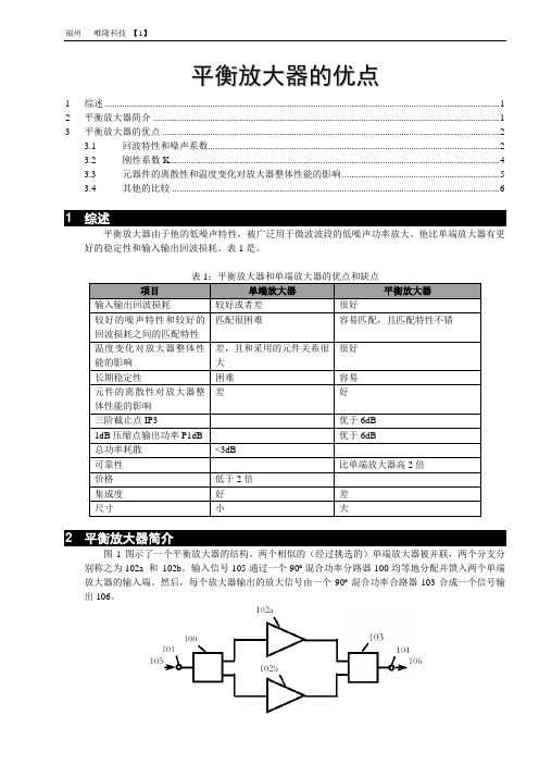
平衡放大器的优点1 综述 (1)2 平衡放大器简介 (1)3 平衡放大器的优点 (2)3.1 回波特性和噪声系数 (2)3.2 刚性系数K (4)3.3 元器件的离散性和温度变化对放大器整体性能的影响 (5)3.4 其他的比较 (6)1 综述平衡放大器由于他的低噪声特性,被广泛用于微波波段的低噪声功率放大。
他比单端放大器有更好的稳定性和输入输出回波损耗。
表1是。
表1:平衡放大器和单端放大器的优点和缺点项目单端放大器平衡放大器输入输出回波损耗较好或者差很好较好的噪声特性和较好的回波损耗之间的匹配特性匹配很困难容易匹配,且匹配特性不错温度变化对放大器整体性能的影响差,且和采用的元件关系很大很好长期稳定性困难容易元件的离散性对放大器整体性能的影响差好三阶截止点IP3 ---- 优于6dB1dB压缩点输出功率P1dB ---- 优于6dB总功率耗散<3dB ----可靠性---- 比单端放大器高2倍价格低于2倍----集成度好差尺寸小大2 平衡放大器简介图1图示了一个平衡放大器的结构。
两个相似的(经过挑选的)单端放大器被并联,两个分支分别称之为102a 和102b。
输入信号105通过一个90º混合功率分路器100均等地分配并馈入两个单端放大器的输入端。
然后,每个放大器输出的放大信号由一个90º混合功率合路器103合成一个信号输出106。
图1:一个平衡放大器的结构图3 平衡放大器的优点举一个例子:一个单端放大器和平衡放大器(他们都使用NE334S01砷化镓场效应管)在3.2 ~3.8 GHz频段的。
其中平衡放大器在每一个分支上使用一个单端放大器。
3.1 回波特性和噪声系数图2画出了一个单端低噪声放大器的原理图,PCB的材料是RO4003,厚度20mil,½ 盎司铜箔。
图2:使用NE334S01砷化镓场效应管的单端低噪声放大器的原理图图3图示了NE334S01砷化镓场效应管具有良好的噪声阻抗。
一汽大众捷达柴油机电控系统
2004 版
内部资料
13
经销商内部培训教程 捷达王柴油电喷一点通 捷达 1.9 L SDI 柴油发动机电子控制系统
2004 版
内部资料
14
经销商内部培训教程 捷达王柴油电喷一点通 宝来发动机电子控制糸统
2004 版
内部资料
15
经销商内部培训教程 捷达王柴油电喷一点通 宝来 1.9 L TDI 柴油发动机电子控制系统
2004 版
内部资料
25
经销商内部培训教程 捷达王柴油电喷一点通
针阀升程传感器G80
针阀升程传感器G80是捷达柴油 发动机系统中重要的传感器之一, 与三缸喷油器和成一体。 信号:采集喷油始点信号 采集喷油持续时间信号 作用: 1. 作为调整柴油发动机正 时 活 塞及喷油时刻的主要信号; 2. 感知喷油持续时间; 3. 可以作为判缸信号。
控制单元从下述传感器信号 中计算一个替代值 • 发动机转速信号G28 • 节气门位置信号G69 • 进气温度信号G72
2004 版
内部资料
23
经销商内部培训教程 捷达王柴油电喷一点通 热膜式空气流量计
结构: -- 热电阻 -- 温度电阻 -- 流量传感器 工作原理:保持空气流量计中热电阻的 温度恒定。 由于流经G70的空气流对热电阻冷却作用不同,因此保持热电阻 温度恒定所需的电流不同。所以,保持热电阻温度恒定所需的电流 值就是吸入空气量的对应值。另外,由于冷空气的冷却作用较强, 需要空气温度作为修正系数。
外部扭矩需求
Air -节气门开度 -进气压力
2004 版
实际扭矩
Spark Fuel
-点火角
-喷油时间
内部资料
11
经销商内部培训教程 捷达王柴油电喷一点通 捷达 1.6L 5阀发动机电子控制系统
- 1、下载文档前请自行甄别文档内容的完整性,平台不提供额外的编辑、内容补充、找答案等附加服务。
- 2、"仅部分预览"的文档,不可在线预览部分如存在完整性等问题,可反馈申请退款(可完整预览的文档不适用该条件!)。
- 3、如文档侵犯您的权益,请联系客服反馈,我们会尽快为您处理(人工客服工作时间:9:00-18:30)。
DESCRIPTIONThe NE334S01 is a Hetero-Junction FET that uses the junction between Si-doped AlGaAs and undoped InGaAs to create very high mobility electrons. Its excellent low noise and high asso-ciated gain make it suitable for TVRO and other commercial systems.NEC's stringent quality assurance and test procedures assure the highest reliability and performance.PART NUMBER NE334S01PACKAGE OUTLINES01SYMBOLSPARAMETERS AND CONDITIONSUNITS MINTYP MAX NF 1Noise Figure, V DS = 2.0 V, I D = 15 mA, f = 4 GHz dB 0.250.35G A 1Associated Gain, V DS = 2.0 V, I D = 15 mA, f = 4 GHz dB 15.016.0I DSS Saturated Drain Current, V DS = 2.0 V, V GS = 0 V mA 2080150g m Transconductance, V DS = 2.0 V, I D = 14 mAmS 7085V GS(off)Gate to Source Cutoff Voltage, V DS = 2.0 V, I D = 100 µA,V -0.2-0.9-2.5I GSOGate to Source Leak Current, V GS = -3.0 VµA0.510NE334S01FEATURES•VERY LOW NOISE FIGURE:0.25 dB TYP at 4 GHz•HIGH ASSOCIATED GAIN:16.0 dB TYP at 4 GHz •GATE WIDTH: 280 µm•TAPE & REEL PACKAGING OPTION AVAILABLE •LOW COST PLASTIC PACKAGEELECTRICAL CHARACTERISTICS (T A = 25°C)MAXIMUM AVAILABLE GAIN, FORWARD INSERTION GAIN vs. FREQUENCYM a x i m u m S t a b l e G a i n , M S G . (d B )M a x i m u m A v a i l a b l e G a i n , M A G . (d B )F o r w a r d I n s e r t i o n G a i n , |S 21S |2 (d B )Frequency, f (GHz)C BAND SUPER LOW NOISE HJ FETCalifornia Eastern Laboratories24201612841PRELIMINARY DATA SHEETNote:1.Typical values of noise figures and associated gain are those obtained when 50% of the devices from a large number of lots were individually measured in a circuit with the input individually tuned to obtain the minimum value. Maximum values are criteria established on the production line as a "go-no-go" screening tuned for the "generic" type but not each specimen.SYMBOLSCHARACTERISTIC UNITS MIN TYP MAX V DS Drain to Source Voltage V 2 2.5I D Drain Current mA 1520P INInput PowerdBmRECOMMENDEDOPERATING CONDITION (T A = 25°C)元器件交易网FREQ.NF MIN G A ΓOPT(GHz)(dB)(dB)MAG ANG Rn/5020.2317.00.77150.1940.2516.00.58430.1860.2814.70.43820.1380.3113.60.321270.08100.3812.50.271750.07120.4811.50.27-1390.10140.6010.50.34-1000.17160.739.60.48-700.29180.888.80.69-560.46SYMBOLSPARAMETERS UNITS RATINGSV DS Drain to Source Voltage V 4.0V GS Gate to Source Voltage V -3.0I DS Drain CurrentmA I DSS T CH Channel Temperature °C 125T STG Storage Temperature °C -65 to +125P TTotal Power DissipationmW300DRAIN CURRENT vs.DRAIN TO SOURCE VOLTAGEABSOLUTE MAXIMUM RATINGS 1 (T A = 25°C)TYPICAL PERFORMANCE CURVES (T A = 25°C)D r a i n C u r r e n t , I D S (m A )Note:1.Operation in excess of any one of these conditions may result in permanent damage.TOTAL POWER DISSIPATION vs.AMBIENT TEMPERATUREAmbient Temperature, T A (°C)Drain to Source Voltage, V DS (V)D r a i n C u r r e n t , I D (m A )DRAIN CURRENT vs.GATE TO SOURCE VOLTAGEGate to Source Voltage, V GS (V) T o t a l P o w e r D i s s i p a t i o n , P T (m W )TYPICAL NOISE PARAMETERS (T A = 25°C)V DS = 2 V, I DS = 15 mA NE334S0150040030020010050100150200250V GS = 0 V-0.2 V-0.4 V-0.6 V1008060402012345100806040200-2.0-1.00TYPICAL CONSTANT NOISE FIGURE CIRCLE (V DS = 2 V, I DS = 15 mA, f = 4 GHz)元器件交易网FREQUENCYS 11S 21S 12S 22KMAG 1(GHz)MAG ANG MAG ANG MAG ANG MAG ANG (dB)TYPICAL COMMON SOURCE SCATTERING PARAMETERS (T A = 25°C)NE334S01V DS = 2 V, I D = 10 mA0.1 1.002-2.0 5.985177.70.00296.60.538-1.3-0.1734.50.50.996-9.7 5.938170.30.01384.00.535-7.50.0626.71.00.981-19.2 5.855160.90.02577.20.529-15.10.1423.71.50.960-28.6 5.765151.70.03671.10.518-22.40.2122.02.00.933-38.0 5.671142.70.04865.50.504-29.90.2620.82.50.903-47.4 5.554133.90.05859.60.488-37.00.3219.83.00.869-57.0 5.429125.10.06853.60.467-44.30.3719.03.50.829-66.6 5.279116.50.07848.30.445-51.50.4318.34.00.788-76.5 5.126108.00.08642.50.420-58.30.4917.74.50.746-86.5 4.95499.40.09437.30.394-65.90.5417.25.00.702-96.7 4.77391.20.10032.30.366-73.20.6016.85.50.662-107.1 4.59383.20.10627.50.339-81.00.6516.46.00.625-117.7 4.42175.50.11122.50.309-88.60.7016.06.50.594-128.4 4.23267.90.11517.50.282-96.40.7515.77.00.566-139.1 4.05960.50.11913.20.257-104.50.7915.37.50.545-149.9 3.88653.20.1219.20.234-112.80.8415.18.00.528-160.6 3.72046.20.123 4.70.210-121.70.8814.88.50.514-170.7 3.56739.30.126 1.20.190-129.40.9214.59.00.511179.1 3.42632.50.128-2.70.172-139.70.9514.39.50.510168.8 3.29225.80.129-6.70.154-150.90.9814.110.00.514158.8 3.15119.00.131-10.80.142-164.7 1.0113.210.50.521148.9 3.02112.50.132-14.20.132177.8 1.0412.411.00.532139.2 2.894 6.30.131-17.90.122158.9 1.0811.711.50.543131.0 2.7640.20.132-21.80.125143.5 1.1111.212.00.562123.0 2.654-6.00.132-25.00.138128.5 1.1210.912.50.580115.5 2.544-12.20.131-28.80.153115.5 1.1410.613.00.598108.5 2.437 -18.10.131-32.00.172104.0 1.1510.313.50.618102.0 2.338-24.20.130-35.50.18995.6 1.1610.114.00.62795.8 2.251-30.30.129-39.00.20387.7 1.189.814.50.64290.1 2.161-36.30.129-42.30.22382.4 1.189.615.00.65784.4 2.074-42.30.130-46.20.24375.6 1.199.415.50.67178.8 1.987-48.60.127-50.00.26269.7 1.219.216.00.68773.6 1.902-54.50.126-54.00.28463.5 1.219.016.50.70468.2 1.821-60.30.126-57.50.30657.0 1.218.817.00.71863.2 1.736-66.00.123-61.20.32852.2 1.238.617.50.73158.7 1.649-71.70.121-64.30.34747.6 1.258.418.00.74953.91.580-77.10.120-68.00.37142.61.238.3Coordinates in Ohms Frequency in GH z V DS = 2 V, I D = 10 mANote:1.Gain Calculations:MAG =|S 21||S 12|K - 1 ).2(K ±∆ = S 11 S 22 - S 21 S 12When K ≤ 1, MAG is undefined and MSG values are used.MSG =|S 21||S 12|, K = 1 + | ∆ | - |S 11| - |S 22|2222 |S 12 S 21|,MAG = Maximum Available GainMSG = Maximum Stable Gainj50+–0元器件交易网FREQUENCYS 11S 21S 12S 22KMAG 1(GHz)MAG ANG MAG ANG MAG ANG MAG ANG (dB)TYPICAL COMMON SOURCE SCATTERING PARAMETERS (T A = 25°C)Note:1.Gain Calculations:MAG =|S 21||S 12|K - 1 ).2(K ±∆ = S 11 S 22 - S 21 S 12When K ≤ 1, MAG is undefined and MSG values are used.MSG =|S 21||S 12|, K = 1 + | ∆ | - |S 11| - |S 22|2222 |S 12 S 21|,NE334S01V DS = 2 V, I D = 15 mA2.0.998-41.77.162140.1 .04268.4.415 -27.5.1041.82 2.5 .927-47.5 6.856133.6.050 65.9 .479-35.8.2326.363.0.860 -61.3 6.603122.0 .05757.5 .423 -43.0.3923.093.5.829 -69.9 6.305114.4 .06454.1 .429-47.9.4221.91 4.0.802 -79.2 6.033106.8 .071 49.6.426 -51.7.4520.95 4.5.716 -87.5 5.68798.5 .075 45.8 .406-56.2.6019.005.0 .659-93.9 5.41591.6.08141.1.394-59.7.6917.885.5 .601 -99.7 5.18484.7 .085 38.9 .374-63.3.7816.896.0 .592 -108.5 5.050 77.6 .091 35.2 .340-68.1.7916.476.5 .550 -118.5 4.912 70.5 .096 30.8 .311-73.0.8415.837.0 .514 -130.2 4.774 63.0 .10227.3 .279 -79.1.8715.26 7.5 .488 -144.5 4.60055.4.10722.0.232-87.5.9114.688.0 .464 -158.9 4.40147.9.10918.6.189-97.7.9614.088.5 .463 -171.7 4.18741.0.11314.9.155-109.3.9813.599.0 .468176.6 3.99734.1.11411.5.134-126.9 1.0015.019.5 .472166.4 3.81227.7.1187.7.121-142.8 1.0214.2110.0 .472156.2 3.62821.5.119 4.7.111-156.2 1.0613.3710.5 .476 147.0 3.47715.6.122 1.0.103-170.1 1.0812.8611.0.476137.8 3.3519.6.124-2.5.098174.4 1.1012.3611.5 .488127.7 3.251 3.5.125-5.8.093157.9 1.1212.0612.0 .518118.1 3.150-2.9.128-9.2.105137.6 1.1011.9812.5 .552109.6 3.036-9.7.130-12.9.131121.0 1.0811.9213.0 .593101.9 2.875-16.4.131-16.7.177107.0 1.0711.7913.5.63595.2 2.714-22.7.129-21.2.22397.8 1.0611.7014.0.66190.1 2.546-28.1.126-22.5.25991.0 1.0811.2914.5.68886.1 2.418-32.6.124-24.9.28487.0 1.0811.1715.0.70782.2 2.327-37.0.127-27.4.31686.0 1.0511.3015.5.71979.7 2.240-41.8.126-28.8.33283.3 1.0411.2016.0.73076.1 2.168-46.8.129-31.6.35281.7 1.0111.5516.5.75271.3 2.100-52.7.131-33.2.38077.4.9810.7417.0.77165.5 2.021-58.4.130-38.5.39872.4.9610.7817.5.80360.4 1.930-65.1.134-42.2.42266.5.8911.0518.0.81755.71.814-70.5.128-44.3.44562.9.9110.92Coordinates in Ohms Frequency in GH z V DS = 2 V, I D = 15 mAMAG = Maximum Available GainMSG = Maximum Stable Gain0+–0元器件交易网FREQUENCYS 11S 21S 12S 22KMAG 1(GHz)MAG ANG MAG ANG MAG ANG MAG ANG (dB)TYPICAL COMMON SOURCE SCATTERING PARAMETERS (T A = 25°C)NE334S01V DS = 2 V, I D = 20 mA0.1 1.002-2.27.768177.70.00383.50.439-1.4-0.0133.90.50.994 -10.77.685169.30.01185.20.436-7.70.0828.41.00.974-21.37.530159.00.02277.50.430-15.50.1825.31.50.946-31.77.350149.10.03371.70.419-23.10.2623.52.00.911 -41.97.155139.50.04266.30.405 -30.50.3322.32.50.870-52.0 6.927130.10.05161.30.388-37.80.4021.33.00.826-62.2 6.682121.00.06055.80.367-45.00.4720.53.50.780-72.4 6.418112.10.06850.50.346-52.10.5319.74.00.733-82.6 6.152103.50.07645.60.322-58.70.6019.14.50.685-93.1 5.87195.00.08340.90.298-66.30.6518.55.00.640 -103.6 5.59286.90.08836.30.272-73.50.7118.05.50.599-114.3 5.32679.10.09431.90.248-81.30.7617.66.00.565-125.1 5.07771.60.09927.70.222-89.00.8117.16.50.536-136.0 4.82264.30.10323.80.198-97.30.8516.77.00.512-146.9 4.59557.20.10719.50.176-106.20.9016.37.50.496-157.8 4.37550.20.11116.00.156-115.60.9316.08.00.483-168.6 4.16643.50.11311.80.138-126.30.9715.78.50.473-178.5 3.97937.00.1178.60.120-135.8 1.0015.39.00.475171.5 3.80730.40.120 5.00.107-149.5 1.0214.29.50.478161.6 3.64424.00.123 1.20.096-165.3 1.0413.510.00.487152.0 3.47917.60.125-2.90.092175.2 1.0613.010.50.498142.5 3.32711.40.128-6.20.097152.5 1.0712.511.00.514133.3 3.181 5.40.128-9.70.103130.1 1.1012.011.50.527125.6 3.036-0.40.130-13.70.116116.5 1.1111.612.00.548118.1 2.911-6.40.131-17.10.137104.9 1.1211.412.50.569111.1 2.789-12.30.132-21.00.16095.2 1.1311.113.00.589104.4 2.670-18.00.132-24.20.18486.9 1.1310.813.50.61098.4 2.562-23.80.132-28.00.20380.3 1.1410.614.00.62092.4 2.466-29.70.134-31.70.21873.7 1.1510.314.50.63686.9 2.368-35.50.134-35.60.23769.5 1.1510.215.00.65281.5 2.272-41.40.134-39.60.25964.1 1.1510.015.50.66876.1 2.178-47.50.134-43.70.27758.7 1.159.816.00.68471.2 2.082-53.20.133-48.00.30053.8 1.169.616.50.70266.1 1.994-58.80.132-51.50.32448.2 1.159.417.00.71661.1 1.904-64.30.130-55.50.34444.0 1.169.217.50.73156.8 1.810-69.80.128-59.10.36239.7 1.179.018.00.75052.01.737-75.00.127-62.60.38535.11.168.9Coordinates in Ohms Frequency in GH z V DS = 2 V, I D = 20 mANote:1.Gain Calculations:MAG =|S 21||S 12|K - 1 ).2(K ±∆ = S 11 S 22 - S 21 S 12When K ≤ 1, MAG is undefined and MSG values are used.MSG =|S 21||S 12|, K = 1 + | ∆ | - |S 11| - |S 22|2222 |S 12 S 21|,MAG = Maximum Available GainMSG = Maximum Stable Gainj50+–0180元器件交易网PART NUMBER AVAILABILITYPACKAGENE334S01BulkS01NE334S01-T1Tape & reel 1K/reel S01NE334S01-T1BTape & reel 4K/reelS01ORDERING INFORMATIONOUTLINE DIMENSIONS (Units in mm)PACKAGE OUTLINE S01NE334S010.125 ±1.5 M A X4. GateEXCLUSIVE NORTH AMERICAN AGENT FOR RF, MICROWAVE & OPTOELECTRONIC SEMICONDUCTORS• Headquarters • 4590 Patrick Henry Drive • Santa Clara, CA 95054-1817 • (408) 988-3500 • Telex 34-6393 • FAX (408) 988-027924-Hour Fax-On-Demand: 800-390-3232 (U.S. and Canada only) • Internet: 7/18/2000DATA SUBJECT TO CHANGE WITHOUT NOTICE元器件交易网。
