2014年3月中国非制造业商务活动指数为54.5%
Eaton AccuProx Analog Sensors 产品指南说明书

Volume 8—Sensing Solutions CA08100010E—October V8-T3-453For Customer Service in the U.S. call 1-877-ETN CARE (386-2273),in Canada call 1-800-268-3578.For Application Assistance in the U.S. and Canadacall 1-800-426-9184.AccuProx Analog SensorsAccuProx Analog SensorsContentsDescriptionPage AccuProx Analog SensorsApplication Guide . . . . . . . . . . . . . . . . . . . . . . .V8-T3-46Product SelectionAccuProx Analog Sensors . . . . . . . . . . . . . .V8-T3-47Compatible Connector Cables . . . . . . . . . . .V8-T3-47Technical Data and Specifications . . . . . . . . . .V8-T3-48Wiring Diagrams . . . . . . . . . . . . . . . . . . . . . . . .V8-T3-50Dimensions . . . . . . . . . . . . . . . . . . . . . . . . . . .V8-T3-50AccuProx Analog SensorsProduct DescriptionThe AccuProx from Eaton’s Electrical Sector is a high performance analog inductive proximity sensor. The AccuProx family of analog sensors provide unmatched sensing range, linearity and resolution in an affordable and compact tubular package.Unlike standard inductive sensors, which send an open or close signal upon target presence or absence, AccuProx analog sensors provide an electrical signal that varies in proportion to the position of the metal target within its sensing range. This makes AccuProx ideal for applications requiring precise position sensing and measurement.The sensing performance of AccuProx sets it apart from traditional analog inductive designs. Utilizingcomponents from the cutting-edge iProx family, AccuProx provides sensing ranges of three to four times that of typical tubular analog inductive sensors—all without compromising accuracy.Unlike many competitive products, which are often hampered by an “S-shaped” output curve, AccuProx outputs are linear.AccuProx has the range and precision to solve your most difficult measurement applications.Application DescriptionTypical Applications ●Part positioning ●Distance, size andthickness measurement ●General inspection and error proofing, such as material imperfection or blemish detection ●Eccentricity or absolute angle detection ●Identification of different metalsSee the Application Guide on Page V8-T3-46 for more detail.Features●Extended linear sensing range of up to 25millimeters—three times longer than standard tubular analog inductive sensors●Outputs available in current (4–20 or 0–20 mA) and voltage (0–10V)●High output resolution and repeatability forapplications requiring precision sensing performance●Robust stainless steel barrel, shock-resistant front cap, polycarbonate end bell and impact-absorbing potting compound●Ideal for extreme temperature or high pressure washdown environments●High noise immunity of 20V/m prevents many problems associated with electrical noiseStandards and Certifications●cUL Listed ●CEDANGERTHIS SENSOR IS NOT ASAFETY DEVICE AND IS NOT INTENDED TO BE USED AS A SAFETY DEVICE. This sensor is designed only to detect and read certain data in an electronic manner and perform no use apart from that, specifically no safety-related use. This sensor product does not include self-checking redundant circuitry, and the failure of this sensor product could cause either an energized or de-energized outputcondition, which could result in death, serious bodily injury, or property damage.For the most current information on this product, visit our Web site:3Application GuidePresenting AccuProx—Unmatched Analog Rangein a Proven PackageHistorically, analog sensorshave been limited by veryshort sensing ranges—aslittle as one or twomillimeters. By utilizingtechnology first perfected inthe iProx family of digitalinductive sensors, AccuProxcan sense objects as far as25millimeters. This extendedrange can be achievedwithout making compromisesoften found in competitiveproducts, such as reducedoutput accuracy.AccuProx utilizes many ofthe proven materials foundin other tubular sensorfamilies. The threaded barreland included mounting nutsare made of stainless steel,which exhibits superiorcorrosion and abrasionresistance versus nickel-plated brass. AccuProx alsofeatures a proprietary internalpotting compound thatabsorbs impacts and vibrationwhile sealing out moisture.The materials used in theconstruction of AccuProx aretime-tested and proven towork.High Output AccuracyAnalog inductive sensors areoften used in applicationsthat require a higher level ofprecision than a standarddigital sensor. For example,applications such as partinspection require a sensorthat can detect very smallvariances. AccuProx has beendesigned with theseapplications in mind.Output accuracy isdetermined by the repeataccuracy, linearity, resolutionand response time of thesensor.Repeat accuracy refers to thevariations in sensing distancebetween successive sensoroperations due to componenttolerances, where alloperating conditions are keptthe same. The repeataccuracy of an 18 millimeter,unshielded AccuProx sensoris less than 20 micrometers.See the chart below for arepeat accuracy comparisonof AccuProx versus thecompetition.Linearity refers to the shape ofthe output curve. Manycompetitive analog sensorsexhibit a wavy or “S-shaped”output curve. This means thata change in target distancemay not always translate intoan equivalent change inoutput, particularly at theinnermost and outermostranges of a non-linear analogsensor. AccuProx features alinear output. See thediagram below for anexample of AccuProxversus a non-linearcompetitive offering.Resolution refers to thenumber of “steps” in thesensor output. A higherresolution is ideal because itwill allow the sensor todetect smaller changes intarget position.An 18 millimeter, unshieldedAccuProx features more than350 output steps, ensuringconsistent performance.Typical Analog ApplicationsMaterial Imperfection orBlemish DetectionEccentricity or AbsoluteAngle DetectionSaw Blade DeflectionV8-T3-46Volume 8—Sensing Solutions CA08100010E—October Volume 8—Sensing Solutions CA08100010E—October V8-T3-473AccuProx Analog SensorsProduct SelectionAccuProx Analog SensorsThree-/Four-Wire SensorsCompatible Connector CablesStandard Cables 3NotesSee listing of compatible connector cables above.1 Published range data is based on a 1 mm thick square target made of Type FE 360 steel per ISO Standard 630.2 Models available in custom output configurations (for example, 1–5V, 0–5V). Contact factory for details.3 For a full selection of connector cables, see Tab 10, section 10.1.Operating VoltageSensing Range 1ShieldingConnection TypeCurrent (0–20 mA) and Voltage (0–10V) Output 2Catalog NumberCurrent (4– 20 mA) Output Only 2Catalog Number12 mm Diameter2-meter cableE59-A12A104C02-CV E59-A12A104C02-C12-meter cableE59-A12C108C02-CVE59-A12C108C02-C118 mm Diameter2-meter cableE59-A18A107C02-CV E59-A18A107C02-C12-meter cableE59-A18C115C02-CVE59-A18C115C02-C12-meter cableE59-A30A112C02-CV E59-A30A112C02-C12-meter cableE59-A30C125C02-CVE59-A30C125C02-C1Voltage StyleNumber of PinsGauge LengthPin Configuration/Wire Colors (Face View Female Shown)PVC Jacket Catalog Number PUR JacketCatalog NumberMicro-Style, Straight Female DC4-pin,3-wire22 AWG6.0 ft (2m)CSDS4A3CY 2202 CSDS4A3RY 222DC4-pin,4-wire22 AWG 6.0 ft (2m)CSDS4A4CY 2202 CSDS4A4RY 220212 mm18 mm 30 mm Micro-Style Straight Female3Technical Data and SpecificationsAccuProx Analog SensorsNotes1Published range data is based on a 1 mm thick square target made of Type FE 360 steel per ISO Standard 630.2The sensor achieves its maximum repeat accuracy after warming up for a period of at least one hour.3Voltage outputs available on models ending in -CV.4Continuous short-circuits can exceed power dissipation ratings and cause eventual destruction.12 mm Models18 mm Models30 mm ModelsDescription Shielded Unshielded Shielded Unshielded Shielded Unshielded PerformanceAnalog operating range 10.5–4 mm1–8 mm1–7 mm1–15 mm1–12 mm1–25 mm Temperature range–40° to 158°F(–40° to 70°C)–40° to 158°F(–40° to 70°C)–40° to 158°F(–40° to 70°C)–40° to 158°F(–40° to 70°C)–40° to 158°F(–40° to 70°C)–40° to 158°F(–40° to 70°C) Temperature drift<± 10%<± 10%<± 10%<± 10%<± 10%<± 10%Conformity<± 10%<± 10%<± 10%<± 10%<± 10%<± 10%Repeat accuracy<25 μm 2<20 μm 2<40 μm 2<20 μm 2<50 μm 2<30 μm 2Minimum repeat accuracy<3.0% at max. range<1.1% at max. range<2.2% at max. range<1.2% at max. range<1.2% at max. range<0.8% at max. range Recovery time<1.0 ms<1.1 ms<1.5 ms<2.0 ms<2.0 ms<3.0 msResponse time200 Hz100 Hz200 Hz100 Hz140 Hz100 HzLinearity tolerance<± 1.0% of full scale<± 1.0% of full scale<± 1.0% of full scale<± 1.0% of full scale<± 1.0% of full scale<± 1.0% of full scale Resolution23 μm max.16 μm max.40 μm max.21 μm max.50 μm max.30 μm max. ElectricalStyle AccuProx Analog,three-/four-wire DCAccuProx Analog,three-/four-wire DCAccuProx Analog,three-/four-wire DCAccuProx Analog,three-/four-wire DCAccuProx Analog,three-/four-wire DCAccuProx Analog,three-/four-wire DC Operating voltage15–30 Vdc15–30 Vdc15–30 Vdc15–30 Vdc15–30 Vdc15–30 VdcCurrent output signal0–20 mA or4–20 mA by model0–20 mA or4–20 mA by model0–20 mA or4–20 mA by model0–20 mA or4–20 mA by model0–20 mA or4–20 mA by model0–20 mA or4–20 mA by model Current output load resistance400–500 ohms400–500 ohms400–500 ohms400–500 ohms400–500 ohms400–500 ohms Current output ripple content± 40 μA max.± 40 μA max.± 40 μA max.± 40 μA max.± 40 μA max.± 40 μA max. Current output minimum change30 μA20 μA50 μA28 μA66 μA40 μAVoltage output signal 30–10V0–10V0–10V0–10V0–10V0–10VVoltage output load resistance 4.7–5.0 kohm(2.5 mA max.)4.7–5.0 kohm(2.5 mA max.)4.7–5.0 kohm(2.5 mA max.)4.7–5.0 kohm(2.5 mA max.)4.7–5.0 kohm(2.5 mA max.)4.7–5.0 kohm(2.5 mA max.) Voltage output ripple content± 10 mV max.± 10 mV max.± 10 mV max.± 10 mV max.± 10 mV max.± 10 mV max. Voltage output minimum change15 mV10 mV25 mV14 mV33 mV20 mVBurden current<20 mA<20 mA<20 mA<20 mA<20 mA<20 mAOutput LED Dual-color,360º viewableDual-color,360º viewableDual-color,360° viewableDual-color,360° viewableDual-color,360° viewableDual-color,360° viewableShort circuit protection Incorporated 4Incorporated 4Incorporated 4Incorporated 4Incorporated 4Incorporated 4Wire breakage protection Incorporated Incorporated Incorporated Incorporated Incorporated Incorporated Reverse polarity protection Incorporated Incorporated Incorporated Incorporated Incorporated Incorporated PhysicalSize See Dimensions on Page V8-T3-50.Enclosure protection NEMA 4, 4X, 6, 6P, 13NEMA 4, 4X, 6, 6P, 13NEMA 4, 4X, 6, 6P, 13NEMA 4, 4X, 6, 6P, 13NEMA 4, 4X, 6, 6P, 13NEMA 4, 4X, 6, 6P, 13 Shock30g half-sine at 11 ms30g half-sine at 11 ms30g half-sine at 11 ms30g half-sine at 11 ms30g half-sine at 11 ms30g half-sine at 11 ms Vibration10–55 Hz,1 mm amplitude10–55 Hz,1 mm amplitude10–55 Hz,1 mm amplitude10–55 Hz,1 mm amplitude10–55 Hz,1 mm amplitude10–55 Hz,1 mm amplitude Housing material Stainless steel,polycarbonate end bell,polyphenylene sulfidefront capStainless steel,polycarbonate end bell,polyphenylene sulfidefront capStainless steel,polycarbonate end bell,polyphenylene sulfidefront capStainless steel,polycarbonate end bell,polyphenylene sulfidefront capStainless steel,polycarbonate end bell,polyphenylene sulfidefront capStainless steel,polycarbonate end bell,polyphenylene sulfidefront cap Termination Micro-connector,potted cable, 2m;Pigtail,micro-connector, 2mMicro-connector,potted cable, 2m;Pigtail,micro-connector, 2mMicro-connector,potted cable, 2m;Pigtail,micro-connector, 2mMicro-connector,potted cable, 2m;Pigtail,micro-connector, 2mMicro-connector,potted cable, 2m;Pigtail,micro-connector, 2mMicro-connector,potted cable, 2m;Pigtail,micro-connector, 2mV8-T3-48Volume 8—Sensing Solutions CA08100010E—October Volume 8—Sensing Solutions CA08100010E—October V8-T3-493AccuProx Analog SensorsAccuProx Analog Performance Graphs Linear Output 12 mm18 mm30 mmMeasurement Resolution 112 mm18 mm30 mmOutput Resolution 212 mm18 mm30 mmNotes1Measurement resolution is the sensor’s ability to detect a change in target position. The measurement resolution is the finest at the highest point in the curve.2Output resolution is the change in output signal relative to target position. The minimum change in output resolution is defined by the lowest point in the curve.3Wiring DiagramsPin numbers are for reference, rely on pin location when wiring.AccuProx Analog SensorsDimensionsApproximate Dimensions in Inches (mm)Micro-Connector ModelsCable and Pigtail ModelsNote1For models ending in -C1 (current output only models), pins 2 and 4 are intentionally connected.Do not connect outputs of -C1 models to separate loads—this sensor should only be connected to a single-output load.Style Output(s)Micro-Connector Models Cable and Pigtail ModelsModels ending in -CV Current: 0–20 mAVoltage: 0–10VSize Shielding A B C D12 mm Shielded 3.05 (77.5) 1.98 (50.3)0.02 (0.50)0.67 (17)Unshielded 3.05 (77.5) 1.64 (41.6)0.36 (9)0.67 (17)18 mm Shielded 2.73 (69.3) 2.00 (50.9)0.02 (0.50)0.94 (24)Unshielded 2.73 (69.3) 1.47 (37.4)0.55 (14)0.94 (24)30 mm Shielded 2.92 (74.1) 2.13 (54.1)0.03 (0.75) 1.41 (36)Unshielded 2.92 (74.1) 1.41 (35.8)0.75 (19) 1.41 (36)Size Shielding A B C D12 mm Shielded 2.46 (62.4) 1.98 (50.3)0.02 (0.5)0.67 (17)Unshielded 2.46 (62.4) 1.64 (41.6)0.36 (9)0.67 (17)18 mm Shielded 2.54 (64.5) 2.00 (50.9)0.02 (0.5)0.94 (24)Unshielded 2.54 (64.5) 1.47 (37.4)0.55 (14)0.94 (24)30 mm Shielded 2.74 (69.6) 2.13 (54.1)0.03 (0.75) 1.41 (36)Unshielded 2.74 (69.6) 1.41 (35.8)0.75 (19) 1.41 (36)V8-T3-50Volume 8—Sensing Solutions CA08100010E—October 。
正常程序
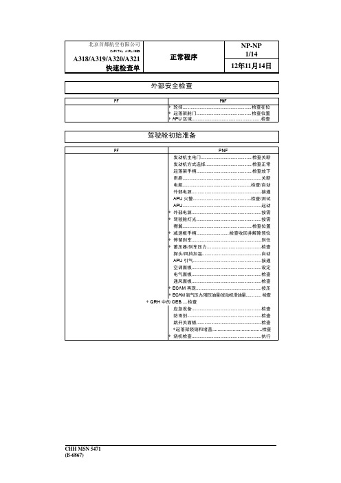
CHH MSN 5471 (B-6867)
北京首都航空有限公司
CAPITAL AIRLINES
A318/A319/0/A321 快速检查单
PF 顶板 所有白灯........................................................... 熄灭 记录器地面控制...............................................接通 驾驶舱舱音记录器...........................................测试 撤离电门........................................................... 按需 ADIRS(大气数据惯性基准系统) ............导航位 外部灯............................................................... 按需 旅客信号牌....................................................... 设定 着陆标高...........................................................自动 组件流量........................................................... 按需 电瓶...................................................................检查 发动机火警..............................................检查/测试 音频转换电门...............................................正常位 第 3 部旅客广播...........................................收听位 维护面板........................................................... 检查 中央仪表板 综合备用仪表系统(ISIS)........................... 检查 时钟..........................................................检查/调整 防滞前轮转弯................................................... 接通 操纵台 音频控制面板(ACP)1................................ 检查 气象雷达........................................................... 设定 转换面板........................................................... 正常 ECAM 状态页................................................... 检查 着陆标高(ECAM)............................... 检查自动 驾驶舱门……............................................检查 推力手柄................................................... 检查慢车 发动机主电门...........................................检查关断 发动机方式选择.......................................检查正常 停留刹车压力................................................... 检查 重力放轮手柄...........................................检查收好 音频控制面板(ACP)2................................ 检查 ATC ..................................................................设定 无线电管理面板............................................... 设定 机场数据........................................................... 获得 ATC 许可............................................................获得 ACARS(飞机通讯寻址和报告系统) 飞行管理引导系统(FMGS)起始: 发动机和机型...................................................检查 数据库有效性...................................................检查 导航台抑制....................................................... 按需 飞行计划起始................................................... 完成 惯性基准系统校准........................................... 视情 飞行计划 A........................................... 完成并检查 爬升/巡航风......................................................输入 飞行计划........................................................... 检查 ...... 起始
A-T Controls FD9-F6 600# Direct Mount Split Body F

Cincinnati, Ohio FAX (513) 247-5462********************FD9F6-3R-20220524Copyright 2013 A-T Controls, Inc.ElectricPneumaticSERIES FD9-F6 600# Direct Mount Split Body Flanged Ball Valve FiresafeSee automated data sheets for pre-sized assembliesEasy to Automate!Triac FD9 Series Flanged Ball Valves feature a direct mount automation pad. The high quality investment castings feature a fully machined bore. The superior live-loaded packing system is accomplished with Belleville washers, “V” ring packing and a unique primary pyramidal stem seal. This advanced sealing system provides protection against stem leaks experienced by ordinary ball valves.available for seat materials. The 50/50 STFE seat option is excellent for services that call for higher temperatures and more difficult applications, including steam. Call us for details.C E R T I F I E D1Graphite Packing FD9C-F6-0150-CXX-X-XXSee part number matrix for itemized options.HOW TO ORDER MANUAL VALVESSAMPLE PART #Valve Series Body MaterialEnd ConnectionSeat MaterialValve SizeSpecial Designation Additional Specials FiresafeSpecial Designation O-RingAdditional Specials*FOR 1/2”-1-1/2” : 4 PCS. OF BOLTS AND NUTS *FOR 2” : 8 PCS. OF BOLTS AND BOLT NUTS $ FOR 1/2” - 1-1/2” : GRAPHITE$ FOR 2” - PTFE: TFM™-1600 GRAPHITE$$ ONLY PRESENT IN 2” DESIGNDIMENSIONS (IN)High Performance, Full Port600# Split Body Flanged Ball Valve Series FD9-F6 (ASME Class 600)2FD9F6-3R-20220524 | Copyright 2013 A-T Controls, Inc. | | (513) 247-5465API 607 - 6th EditionC E R T I F I ED F I RE S AF EHigh Performance, Full Port600# Split Body Flanged Ball Valve Series FD9-F6 (ASME Class 600)2004006008001000120014001600-100-50050100150200250300350400450500550600P r e s s u r e (p s i )(°F)CTFE STFEPTFETFM-16003FD9F6-3R-20220524 | Copyright 2013 A-T Controls, Inc. | | (513) 247-5465ASME Class 600 Flanged Firesafe Tested to API-607Direct MountSERIES FD9-F6 600# Flanged Direct Mount FiresafeAPI 607 - 6th EditionC E R T I F I E DDIMENSIONS (IN)DIMENSIONS SHOWN ARE FOR ASSEMBLIES SIZED FOR 80 PSI SUPPLY4SAMPLE PART #FD9-6C-100/3RED-XXSee automated part number matrix on back cover for complete partnumber and options.Valve SeriesFiresafe Seat MaterialValve SizeEnd ConnectionTRIAC Actuator SeriesActuator Size Double ActingSUFFIX 1: Solenoids SUFFIX 2: Limit Switch Other options available - call for details.Actuators are sized based on full differential pressure with clean water. Consult the Application Sizing Guide for assistance with sizing actuators.FD9F6-3R-20220524 | Copyright 2013 A-T Controls, Inc. | | (513) 247-5465DIMENSIONS (IN)DIMENSIONS SHOWN ARE FOR ASSEMBLIES SIZED FOR 80 PSI SUPPLYSERIES FD9-F6 600# Flanged Direct Mount FiresafeASME Class 600 Flanged Firesafe Tested to API-607Direct MountAPI 607 - 6th EditionC E R T I F I E D5SAMPLE PART #FD9-6C-100/3RFS-XXSee automated partnumber matrix on back cover for complete partnumber and options.Valve SeriesFiresafe Seat MaterialValve SizeEnd ConnectionTRIAC Actuator SeriesActuator Size Double Acting SUFFIX 1: Solenoids SUFFIX 2: Limit Switch Other options available - call for details.Actuators are sized based on full differential pressure with clean water. Consult the Application Sizing Guide for assistance with sizing actuators.FD9F6-3R-20220524 | Copyright 2013 A-T Controls, Inc. | | (513) 247-5465ASME Class 600 Flanged Firesafe Tested to API-607Direct MountSERIES FD9-F6 600# Flanged Direct Mount FiresafeAPI 607 - 6th EditionC E R T I F I E DDIMENSIONS (IN)DIMENSIONS SHOWN ARE FOR ASSEMBLIES SIZED FOR 80 PSI SUPPLY6SAMPLE PART #FD9-6C-100/WEA1-XXSee automated partnumber matrix on back cover for complete partnumber and options.Valve SeriesFiresafe Seat MaterialValve SizeEnd ConnectionTRIAC Actuator SeriesActuator SizeOn-Off SUFFIX 1: Voltage SUFFIX 2: Options Other options available - call for detailsActuators are sized based on full differential pressure with clean water. Consult the Application Sizing Guide for assistance with sizing actuators.FD9F6-3R-20220524 | Copyright 2013 A-T Controls, Inc. | | (513) 247-5465HOW TO ORDER:Manual ValvesChemraz® is a registered trademark of Greene, Tweed & Co.Markez® is a registered trademark of Marco Rubber & Plastic Products Inc.Perlast® is a registered trademark of Precision Polymer Engineering Limited Viton® is a registered trademark of E. I. DuPont de Nemours...TFM™ is a trademark of Dyneon™, a 3M Company.7FD9F6-3R-20220524 | Copyright 2013 A-T Controls, Inc. | | (513) 247-5465HOW TO ORDER:Automated Valves w/ OptionsViton® is a registered trademark of E. I. DuPont de Nemours..TFM™ is a trademark of Dyneon™, a 3M Company.(10) Special DesignationSAMPLE PART #(2) Valve Series(3) Body/Ball/StemMaterial(6) Valve Size(5) Seat, Lining & TrimMaterial(4) End Connection(7A) TRIAC Actuator Series(7A) Actuator Size(7B) Double Acting(8) Accessory(9) AccessoryAUTOMATED VAL VEFD9-6C-150/3RFD-XX-_(1) PrefixFD9F6-3R-20220524Copyright 2013 A-T Controls, Inc.9955 International Blvd.Cincinnati, Ohio 45246PHONE (513) 247-5465FAX (513) 247-5462********************8**2500 & 3500 60 psig spring3P=Teflon™ (PTFE) Coating。
捷豹报警公开价-2014

捷豹套装公开价JK-20-CN(新)60F,RC-40,JA-60N,JA-60P)¥2,718JK-21-CN(新)电话线拨号无线套装(包括JA63KRX,JA-60E,RC-40,JA-60N,JA-60P)¥2,386JK-22(新)GSM 无线报警套装 (包括JA63KRG,JA-60F,RC-40,JA-60N,JA-60P)¥4,252JK-23(新 )GSM 无线报警套装 (包括JA63KRG,JA-60E,RC-40,JA-60N,JA-60P)¥4,017JK-84包含JA-82KR主机,JA-83M门磁,JA-83P红外,RC-86遥控,JA-81F液晶键盘,JA-80L室内警号,PC-01RFID卡,SA-200有线门磁,2.2AH后备电池各1个¥4,663JK-82包含JA-82KR主机,JA-82Y GSM模块,JA-83M门磁,JA-83P红外,RC-86遥控,JA-81F液晶键盘,JA-80L室内警号,PC-01RFID卡,SA-200有线门磁,2.2AH后备电池各1个¥7,813AZOR START主机,读卡器,红外,门磁,电源各1个,ID卡2张¥6,312AZOR PLUS主机,读卡器,电源各1个,3个红外,2个门磁,2张ID卡¥7,339EYE-02 EYE-02是一个独立的安全报警监控系统,易于自己动手安装和操作,它可以录制视频影像资料,并通过GSM网络点播、传输个人单帧影像资料等。
¥5,889EYE-02 3G版EYE-02是一个独立的安全报警监控系统,易于自己动手安装和操作,它可以录制视频影像资料等。
¥7,853OASIS-主机及通讯模块JA-82K报警主机,积木式构造,提供4个有线防区¥791JA-82R无线模块,支持50个无线设备¥628JA-82C有线防区输入模块,扩展10个有线防区,主机最多可使用1个该模块¥450JA-82Y GSM通讯模块,8组电话号码,短信,支持录音,2个报警中心,支持图像传输¥3,087 JA-80X电话线模块,同JA-65X¥574 JA-82V网络通讯模块¥1,208 OASIS-探测器系列JA-83M门磁,不支持有线输入,锂电池,三年,空旷300米¥544JA-81M门磁,支持有线输入,锂电池,三年,空旷300米¥559 JA-82M窗磁,锂电池,三年,空旷200米,窗户专用¥631 2014原装欧洲进口捷克捷豹报价单¥677 JA-80P红外,支持有线输入,锂电池,三年,空旷300米,12米120°JA-83P红外,锂电池,三年,12米120°,空旷300米¥670¥1,712 JA-84P红外+摄像机,锂电池,三年,12米120°,空旷300米JA-85P吸顶红外,锂电池,三年,半径5米,空旷100米¥704¥809 JA-86P双区红外,恶劣环境,锂电池,三年,12米,空旷300米¥3,531 JA-89P室外专用,双区红外,锂电池,三年,12米,空旷300米JA-80PB玻璃破碎+红外,锂电池,三年,空旷300米¥1,187 JA-85B玻璃破碎,锂电池,9米探测,三年,空旷100米¥689¥825 JA-80S烟雾探测器,锂电池,50平方米探测,三年,空旷100米¥870 JA-80G气体泄漏探测器,市电供电,50立方米探测,三年,空旷200米RC-88紧急按钮,锂电池,三年,空旷300米¥483 RC-87便携式紧急按钮,锂电池,三年,空旷50米¥450¥1,027 JA-80W红外+微波,12米110°,电池寿命2年,空旷300米JA-82SH振动/倾斜,10-45°,电池2年,空旷300米¥616 JA-80IR无线对射,2光束60米,电池3年,空旷300米¥8,517 OASIS-键盘¥1,238 JA-81F液晶键盘,锂电池,三年,内置读卡器,空旷100米JA-81E有线液晶键盘,内置读卡器¥900¥1,081 JA-80H室外键盘,带门铃和刷卡功能,有线与WJ-80连接WJ-80室外键盘,室外读卡器连接器,可控电锁¥664 OASIS-警号JA-80A室外警号,AC24V供电,空旷300米¥1,293 JA-80L室内警号,同UC-260¥522 OASIS-其他可选设备AN-81加长天线¥595 JA-80Z信号中继器,距离增加一倍¥1,419 UC-82 接收器,DC12V¥667 AC-82 接收器,AC220V¥701 PC-01RFID CARD ID卡¥21 AZRO SYSTEMAZ-10P红外,功能同60P¥574 AZ-10M门磁,功能同60N¥453 AZ-10T ID卡,钥匙扣外形¥121 AZ-10R遥控器,功能同RC11¥242 AZ-10S烟感,功能同63S¥846 PROFI-63系列主机JA-63KRG PROFI16无线和4有线防区,GSM拨号,不带电池¥3,411¥1,738 JA-63KRX-CN16无线和4有线防区,电话线拨号和语音拨号,不带电池JA-63KR-CN16无线和4有线防区,不带电池¥1,312 JA-63K PROFI4有线防区(带电源)¥754PROFI-63系列键盘¥689 JA-60F无线键盘 配JA63 PROFI 和JA-65 MASTER 主机用¥525 JA-60E有线键盘 配JA-63 PROFI 和JA-65 MASTER主机用PROFI-63系列无线探测器JA-60IR(新)无线红外栅栏-5米¥4,395JA-60N无线门磁带外接输入端,AAA电池¥394JA-60P无线红外探测器,AAA电池¥508 JA-60V无线室外红外探测器¥3,148 JA-60B 无线音频双技术玻璃破碎探测器,AAA电池¥508JA-63S无线光电式烟雾探测器带IR遥控测试功能,AAA电池¥724 JA-60G无线气体泄露探测器¥755 PROFI-63系列遥控器RC-112键式遥控器黑色(RC-11B白色,RC-11A 木色)¥141RC-864键式遥控器,黑色,(RC-86W 白色),兼容63和80系统¥152 RC-22无线墙装或桌下装遥控器或紧急按钮¥177 RC-28无线门铃配UC-260用¥190RC-60无线发射器带有线输入端子,用于对主机布防,撤防,紧急报警用¥361 PROFI-63系列警号JA-63A无线室外警号,带变压器,后备电池¥1,049UC-260无线室内警号带音乐声,门铃声,230V交流插头¥333UC-261(新)UC-261 无线室内警号与报警主机是双向通讯,它可作为无线警号,无线门铃,无线扬声器。
UV-curing behavior and adhesion performance
UV-curing behavior andphotoinitiators blended withfor UV-crosslinkable acrylic pressure sensitive adhesivesHyun-Sung Do 1,Jin-Hee Park,Hyun-Joong Kim *Laboratory of Adhesion and Bio-Composites,Program in Environmental Materials Science,Seoul National University,Seoul 151-921,Republic of Koreaa r t i c l e i n f o Article history:Received 6December 2007Received in revised form 1July 2008Accepted 15July 2008Available online 6August 2008Keywords:UV-crosslinkable acrylic PSAs Polymeric photoinitiatorsHydrogenated rosin epoxy methacrylates Tackifier blendsblended at different levels with the synthesized,UV-crosslinkable polyacrylates for use as PSAs.The effect of the new tackifier,HREM,on the properties of the UV-crosslinkable PSAs was examined in comparison with the properties exhibited by PSA/hydrogenated rosin blends.The characteristics of these PSA/tackifier blends were examined by Fourier-trans-form infrared (FTIR)spectroscopy,differential scanning calorimetry (DSC)and an advanced rheometric expansion system (ARES).In addition,the adhesion performance of the PSA blends was investigated using probe tack tests.DSC and ARES revealed all the PSA blends with HREM or hydrogenated rosin to be miscible at the molecular level.The glass transition temperature (T g )of HREM was À25.6°C,which is lower than that of other commercially available rosin tackifiers.FTIR revealed changes in the relative concentration of benzophe-none groups in the PSAs at 1580cm À1,which demonstrated that the crosslinking efficiency is proportional to the benzophenone content and UV dose,but decreases with increasing hydrogenated rosin content.However,the reduced crosslinking reaction efficiency was improved in the PSA/HREM blends due to the low T g of HREM which only slightly increased the T g of the PSA blends.Moreover,the relative initial decrease in the probe tack of the PSA/HREM blends was lower than that of the PSA/hydrogenated rosin blends after UV irradiation.Ó2008Elsevier Ltd.All rights reserved.1.IntroductionUV-curing of multifunctional monomers produces highly crosslinked networks with high thermal stability,mechani-cal strength,and resistance to solvent absorption.The polymeric networks produced have many industrial appli-cations,particularly as coatings for flooring and furniture,dental restorative materials,optical fiber coatings,hard and soft contact lenses,and photolithography [1–3].Multi-functional acrylates and methacrylates are the monomers used most widely for photo-polymerization [4–10].The photo-polymerization of various acrylates has been studied using differential scanning calorimetry (DSC),dilatometry,dynamic mechanical testing,and real-time infrared spec-troscopy [4,8,11,12].Acrylic ester monomers are widely used to synthesize pressure sensitive adhesives (PSAs)through solution or emulsion polymerization.These synthesized acrylic PSAs have excellent properties.Their saturated nature makes0014-3057/$-see front matter Ó2008Elsevier Ltd.All rights reserved.doi:10.1016/j.eurpolymj.2008.07.046*Corresponding author.Tel.:+8228804784;fax:+8228732318.E-mail address:hjokim@snu.ac.kr (H.-J.Kim).1Present address:Planning Manufacturing Engineering 2Group PDP Business Division,Samsung SDI Co.,Ltd.,South Korea.European Polymer Journal 44(2008)3871–3882Contents lists available at ScienceDirectEuropean Polymer Journaljournal homepage:www.elsevi e r.c o m /l o c a t e /e u r o p o l jthem transparent,colorless,and resistant to yellowing from sunlight or oxidation[13].However,as these synthe-sized acrylic PSAs consist of linear molecules that are held together by physical crosslinking,van der Waals forces,or by hydrogen bonding,they have limited mechanical and thermal properties.A variety of UV-curing techniques have been used to crosslink these acrylic PSAs in an attempt to improve their dimensional stability[13–15].In general,acrylic PSAs had not previously been formulated with tackifier resins because their adhesion properties can be adjusted by varying their monomer com-position.However,recent studies have described the blending of acrylic PSAs and tackifier resins for efficient modification of their adhesion properties[16–18].Tackifi-ers improve the tack property of the base polymers by altering both their surface and viscoelastic properties [19].However,because most tackifiers do not have a UV reactive site,they act as non-crosslinkable species during UV-curing,and retard the UV-curing rate of PSAs.In addi-tion,the miscibility between acrylic PSAs and the tackifier needs to be considered.Moreover,there is a limitation in the blending ratio because most tackifiers have a high glass transition temperature(T g)[16,20–22].In this study,a mono-functional hydrogenated rosin epoxy methacrylate(HREM)was synthesized from a hydrogenated rosin and glycidyl methacrylate(GMA),as a new tackifier,in an attempt to overcome the common problems of tackifiers in a UV-crosslinking PSA system. This HREM was then blended at different levels with the synthesized UV-crosslinkable acrylic PSAs.The UV-curing behavior and characteristics of these PSA blends were examined by comparing the Fourier-transform infrared (FTIR)spectroscopy,DSC,and advanced rheometric expan-sion system(ARES)data with those of the acrylic PSA/ hydrogenated rosin blends.In addition,the adhesion per-formance of the PSA blends was evaluated through probe tack measurements.2.Experimental2.1.MaterialsThe2-ethylhexyl acrylate(2-EHA),butyl acrylate(BA), vinyl acetate(VAc),and acrylic acid(AA)used to synthesize the acrylic PSAs were purchased from Junsei Chemicals Co.,Ltd.(Japan).The2-(acryloyoxy)ethyl4-(4-chlorobenzoyl)benzoate(P-36)used as the polymerizable photoinitiator was obtained from SK Cytec Co.,Ltd.(South Korea).Ethyl acetate(analytical grade,Junsei Chemicals Co.,Ltd.,Japan)and2,20-azobisisobutyronitrile(AIBN,Dae-jung Chemicals&Metals Co.,South Korea)were used as the solvent and initiator for synthesizing the acrylic PSAs, respectively.Hydrogenated rosin(Foral AX-E,Eastman Chemical Co., Ltd.,Netherlands)and GMA(Junsei Chemical Co.,Ltd., Japan)were used to synthesize the HREM in methyl ethyl ketone(MEK,Samchun Pure Chemical Co.,Ltd.,Korea). Hydroquinone(HQ,Sigma–Aldrich)and tetramethylam-monium bromide(TMAB,Sigma–Aldrich)were used the inhibitor and catalyst,respectively.2.2.Synthesis of UV-crosslinkable polymeric photoinitiators and HREMThe UV-crosslinkable polymeric photoinitiators were synthesized using2-EHA,BA,VAc,AA,and P-36through solution polymerization initiated by1.5wt%AIBN in ethyl acetate at40wt%solids.The polymerization was per-formed in a500-ml,four-necked,round-bottomedflask equipped with a thermometer,condenser,dropping funnel, and mechanical stirrer.The typical synthetic method was as follows.Theflask was charged with50%of a monomer and solvent mixture,and then polymerization was started at80°C in a heating mantle for2h.After polymerization, the remaining50%of the monomer and solvent mixture was added over1h,and theflask was kept at80°C for 3h[23].Table1shows the composition of polymeric photoinitiators used without purification in the synthe-sized,UV-crosslinkable,acrylic PSAs.HREM was synthesized from hydrogenated rosin and GMA in MEK.An equimolar mixture of hydrogenated rosin and GMA with1wt%TMAB and0.2wt%HQ dissolved in MEK as50%solid was charged into a500ml,three-necked, round-bottomedflask.The synthesis was carried out at 80°C for24h.The solution was evaporated to remove the MEK.The residue was washed with a5%sodium hydroxide solution to remove the HQ and dried in a vac-uum oven at40°C for72h.Thefinal product was used as HREM.Fig.1shows the procedure for the formation of HREM[24].Each hydrogenated rosin and HREM as a tackifier was blended with the synthesized polymeric photoinitiators at levels ranging from0to30wt%(on a non-volume basis).Table1PSA characteristicsSample Solvent PSA composition(wt%)M w(Â105)PDI T g2-EHA BA VAc AA P-36P01Ethyl acetate65201050.1 6.6 3.1À48.7 P03Ethyl acetate65201050.3 6.4 2.5À50.6 P06Ethyl acetate65201050.6 6.3 2.4À47.9 P09Ethyl acetate65201050.9 6.5 2.8À53.1 P12Ethyl acetate6520105 1.2 6.1 2.1À51.2 P010a Methanol65201050.1–––a Gel formed during polymerization.3872H.-S.Do et al./European Polymer Journal44(2008)3871–38822.3.Preparation of PSA samples and UV-curingThe PSA samples were prepared by coating the PSA blends onto the corona-treated,polyethylene terephthal-ate (SKC Co.,Ltd.,South Korea)at 20l m using a bar coater (No.22),followed by drying in an oven at 70°C for 10min.These dried PSA samples were maintained at 22±2°C and 60±5%RH for 24h before testing,and were cured using a conveyer belt-type,UV-curing machine equipped with a high-pressure mercury lamp (100W/cm,main wave-length:340nm).A cold mirror was used as a reflector to avoid the heating effect of the mercury lamp.The UV doses applied were 0,200,600,1000,1400,1800,and 2200mJ/cm 2,as determined using an IL 390C Light Bug UV radiom-eter (International Light Inc.,USA).2.4.MeasurementsThe T g was measured using a DSC unit (TA,Q-1000).The samples were first cooled to À85°C and then heated to 60°C at 10°C/min for the first scan.They were then quenched immediately to À85°C and maintained at this temperature for 3min.The samples were reheated to 200°C at 10°C/min during the second scan.The T g values were obtained using the second scans to ensure thermo-gram reproducibility and freedom from thermal history effects.The viscoelastic properties (G 0,tan d )of the PSA blends were determined using an ARES unit (Advanced Rheomet-rics Expansion System,Rheometric Scientific Inc.)in 8mm parallel plate mode.A typical scan covered the range from À80to 200°C at 5°C/min with a frequency of 6.3rad/s.The infrared reflectance spectra were measured using an FTIR spectrometer (JASCO FTIR-6300)with a Mylar beam splitter.The spectra were collected for 32scans to reduce the noise at a resolution of 8cm À1between 650and 4000cm À1.During UV-curing of the PSA blends,the benzo-phenone groups were copolymerized,which involved a loss of conjugation between their carbonyl groups and the aro-matic rings,and a reduction of the absorption at ca.1580cm À1[25,26].Therefore,the conversion was analyzed by observing the characteristic absorption band at approxi-mately 1580cm À1and the relative benzophenone concen-tration was estimated [8,25].The C @O stretching vibration at about 1732cm À1of acrylic monomer was adopted as an internal standard band for calculation in order to compen-sate an effect of difference in thickness existing in PSA sam-ples.The relative benzophenone concentration as a function of the UV dose and photoinitiator concentration of the PSA samples was calculated using the following equation:Relative concentration of UV-cured group ð%Þ¼½A P UV =½A C UV ½A P 0=½A C 0Â100where ½A P UV is the peak area of the absorbance at approx-imately 1580cm À1in the normalized spectrum of the UV-cured sample,½A C UV is the peak area intensity of the C @O group in the normalized spectrum of the UV-cured sample,½A P 0is the peak area of absorbance at approxi-mately 1580cm À1in the normalized spectrum of the sam-ple before UV-curing,and ½A C 0is the peak area intensity of the C @O group in the normalized spectrum of the sample before UV-curing.cured PSA samples were weighed and immersed in for 4days at 50°C,and then screened and dried at 80°C to a constant weight.The gel fraction of the samples was calculated using the following equation:Gel fraction ð%Þ¼W tÂ100where W 0and W t are the PSA weights before and after immersion,respectively.The tack measurements of the PSA samples on glass plates were carried out with a TA-XTi Texture Analyzer (Texture Technologies Co.,UK)at 20°C using a probe tack consisting of a polished stainless steel (type 304),5mm-diameter,cylinder probe.The measurements were con-ducted at a debonding speed of 0.5mm/s under a constant pressure of 100g/cm 2and a swell time of 1s.Fig.1.Synthesis of the hydrogenated rosin epoxy methacrylate (HREM).H.-S.Do et al./European Polymer Journal 44(2008)3871–388238733.Results and discussion3.1.Miscibility of PSA blends by DSC and T g measurementsThe phase structure of each blend was assessed by the number of T g transitions observed in the thermograms; two transitions are a clear indication of phase separation. Miscibility was indicated by a single glass transition located at a temperature intermediate between those of the pure components[27].Tackifying a PSA is limited by its miscibility,which highlights the need for miscibility measurements[21].Fig.2(a)shows the T g of hydroge-nated rosin and a P01/30wt%hydrogenated rosin blend. The T g of the hydrogenated rosin was approximately 132.1°C.However,the T g curve disappeared after blend-ing with PSA.In addition,all PSAs blended with hydroge-nated rosin were transparent.Each of the blends with varying hydrogenated rosin contents showed a single T g curve,as shown in Fig.2(b).The T g of P01was approxi-matelyÀ47.8°C,which increased gradually with increas-ing hydrogenated rosin content toÀ41.3,À37.1,and À33.2°C at10and20–30wt%hydrogenated rosin,respec-tively.The existence of a single composition-dependent T g is evidence that PSA is miscible with hydrogenated rosin at the molecular level.Fig.3(a)shows the DSC result for HREM.The T g of HREM was approximatelyÀ25.6°C,and an exothermic reaction was observed at146.4°C.HREM was cured thermally at this temperature because it has an acrylate group,even though it does not have a thermal initiator.Fig.3(b)shows that the T g curve of HREM had disap-peared after blending with P01,and the blends showed a single T g below the T g of HREM.Furthermore,all PSA/ HREM blends were transparent.The T g of P01,À47.8°C, increased slightly with increasing the HREM content to À46.1,À43.1,andÀ42.2°C at10,20,and30wt%HREM, respectively.The existence of a single T g indicates that HREM is also miscible with PSA at the molecular level. Its rate of width increase was very small compared with that of the PSA/hydrogenated rosin blends,which was attributed to the low T g of HREM.As the T g of hydroge-nated rosin decreased drastically from132.1to À25.6°C after reacting with GMA,the T g increase of the PSA/HREM blends with increasing HREM content in PSA was small.3.2.Viscoelastic properties of PSA blendsThe viscoelastic properties of the PSA blends were determined using ARES measurements.A compatible blend will show a single broad transition,which is the weight average of the individual transitions[27].TheinfluenceFig.2.DSC thermograms of(a)hydrogenated rosin and PSA(P01)/30wt%hydrogenated rosin blend,and(b)PSA(P01)/hydrogenated rosin blendswith increasing hydrogenated rosincontent.Fig.3.DSC thermograms of(a)HREM and PSA(P01)/30wt%HREM blend,and of(b)PSA(P01)/HREM blends with increasing HREM content.3874H.-S.Do et al./European Polymer Journal44(2008)3871–3882of a tackifier on the modulus is another index of compati-bility.A decrease in the elasticity of a polymer matrix can be achieved by mixing with viscous compounds.Generally, tackification decreases G0and increases tan d[13,28].Fig.4(a)shows the changes in G0of the P01blends at different hydrogenated rosin contents.G0decreased con-tinuously with increasing content of hydrogenated rosin blended into the PSA.A lower G0favors bonding by increasing the efficiency of contact between PSA and the substrate[29].The tack is related to the tackifier concentration because the tackifier alters the viscoelastic properties of the PSAs[30].PSA should deform easily in the short time required to make intimate contact with substrates with a high tack value[31].Therefore,viscous flow is essential for the quick deformability of PSAs.A probe tack test also includes the process of detaching PSA from the surface.The measured tack results indicate the resistance to detachment.Therefore,a higher G0va-lue is also desired.However,G0cannot increase indefi-nitely while maintaining good tack because good wetting of the surface would be prevented if G0is too high[13].Fig.4(b)shows the changes in the T g of the blends (temperature at peak tan d)in the ARES test,as the hydrogenated rosin was mixed with an acrylic PSA.The T g of all blends increased with increasing hydrogenated rosin content,which is in accordance with the DSC re-sults.In addition,only one glass transition range was de-tected for all PSA blends,indicating that the synthesized acrylic PSAs were miscible with the hydrogenated rosin. As mentioned previously,formulating a PSA with a tack-ifier usually decreases the modulus and increases the T g, but a high tackifier loading increases the modulus.A lower modulus always promotes bond formation,while an increased T g causes bond rupture[19,32].Fig.5(a)shows that the G0of the P01/HREM blends decreased with increasing HREM pared with Fig.4,the hydrogenated rosin with high T g and the HREM with low T g,both tackifiers lowered G0but the low T g HREM showed a more significant decrease in G0.Fig.5(b)shows the changes in T g(temperature at peak tan d)as HREM was blended into the acrylic PSA, P01.While the T g of the PSA/hydrogenated rosin blends increased with increasing hydrogenated rosin content, the PSA/HREM blends showed a similar T g:À20.4,À19.6,andÀ19.7°C for PSA blends containing0,10, and30wt%of HREM,respectively.These results were in accordance with the DSC results shown in Fig.3,i.e. the T g values increased slightly with increasing HREM content.In addition,only one glass transition point was detected for all PSA blends,indicating that the syn-thesized acrylic PSAs are miscible withHREM.Fig.4.Viscoelastic curves of the P01/hydrogenated rosin blends as afunction of the hydrogenated rosin content:(a)G0and(b)tan d.Fig.5.Viscoelastic curves of the P01/HREM blends as a function of HREMcontent:(a)G0and(b)tan d.H.-S.Do et al./European Polymer Journal44(2008)3871–388238753.3.UV-curing behavior3.3.1.FTIR spectroscopyThe synthesized PSAs with benzophenone as the pen-dant groups in the polymer backbone were polymeric photoinitiator compounds.After UV irradiation,the PSAs were crosslinked without the need for further addition of photoinitiators,functional monomers and oligomers [14].During UV-curing of the PSA blends,the copolymerized benzophenone groups were converted.The resonance in the benzene ring showed strong stretching vibrations at approximately 1500cm À1.However,a band at approxi-mately 1580cm À1could be observed when these groups were conjugated to the C @O,such as benzophenone [33].When exposed to UV,the C @O in the benzophenone was excited to a triplet state through a singlet state,which then abstracted hydrogen from a suitable hydrogen donating group.Therefore,the characteristic absorption bands at approximately 1580cm À1decreased in intensity due to the loss of conjugation between the C @O and resonance in the aromatic ring due to the conversion of the C @O group [14,26,34].Fig.6shows the changes in the relative concentration of benzophenone groups in the PSA/hydro-genated rosin blends at approximately 1580cm À1with increasing UV dose and hydrogenated rosin content.Before blending with the hydrogenated rosin,the benzophenone concentration decreased gradually with increasing UV dose (Fig.6(a)).However,in the case of the P01/20and 30wt%hydrogenated rosin blends,the benzophenone con-centration remained relatively unchanged with increasing UV dose,which was similar to that of the P03blends.In contrast,the benzophenone concentration of P03without hydrogenated rosin showed a sharp decrease from 100%to approximately 35%.In the case of the P06,P09,and P12blends with 20and 30wt%hydrogenated rosin,the benzophenone concentration began to decrease with increasing UV dose.At a UV dose of 2200mJ/cm 2,the ben-zophenone concentration in the P06blends containing 0–30wt%of hydrogenated rosin decreased considerably compared to the ones at a UV dose of 200mJ/cm 2.In the PSA blends containing the higher hydrogenated rosin content,the benzophenone concentration still remained at a high value despite the high UV dose.Although the ben-zophenone concentration of these P09and P12blends had decreased to 20%,22%,40%,and 60%,and to 15%,18%,25%,and 35%at a UV dose of 2200mJ/cm 2,respectively,the concentration of benzophenone remained high in the PSA blends containing the higher hydrogenated rosincontent.Fig.6.Changes in the relative concentration of benzophenone groups in the PSAs at 1580cm À1with different UV doses,benzophenone content,and hydrogenated rosin content:(a)0,(b)10,(c)20,and (d)30wt%hydrogenated rosin in PSA.3876H.-S.Do et al./European Polymer Journal 44(2008)3871–3882These results were attributed to the ability of the tackifiers to act as UV-curing retardants.The mixed hydrogenated rosin expanded the distance of the PSA polymers but re-duced the PSA polymer mobility by increasing T g .Fig.7(b)shows the changes in the relative concentra-tions of benzophenone in the PSA/10wt%HREM blends with increasing UV dose.At a UV dose of 200mJ/cm 2,the rate of benzophenone loss in these PSA blends increased rapidly with increasing benzophenone content,and it in-creased gradually at a UV dose >600mJ/cm 2except for the P01blends.At a UV dose of 2200mJ/cm 2,the relative benzophenone concentration in the P01,P03,P06,P09,and P12blends with 10wt%HREM was 87.9%,43.1%,17.2%,13.8%,and 9.2%,respectively.These values were lower than those of the PSA/10wt%hydrogenated rosin blends with the exception of the P01blends,which were 72.1%,53.1%,20.2%,21.8%,and 16.2%,respectively,at this UV dose.This result indicated that the mobility of the PSA polymer increased when the T g of the blended HREM was sufficiently lower (À25.6°C)than that of the hydroge-nated rosin.Hydrogenated rosin increased the stiffness of the PSA polymers because its high T g (132.1°C)increased the T g of the PSA blends.This reduced UV-crosslinking rate increased the concentration of the remaining benzophe-none.The T g is related to the PSA chain flexibility in that chain flexibility decreases with increasing T g of the PSA blends.In general,the conversion at the maximum rate of polymerization increases as the chain flexibility increases,i.e.T g decreases.The reason for the increased conversion at the maximum rate is the delayed gel effect [10].As the mobility of the system was enhanced in the PSA blends containing HREM compared to those contain-ing the hydrogenated rosin,the gel effect was delayed and the level of crosslinking was maximized.Fig.7(c)shows the changes in the relative benzophenone concen-tration in PSA/20wt%HREM blend with increasing UV dose.As shown in Fig.7(b),the rate of benzophenone loss in the PSA blends increased rapidly with increasing benzo-phenone content at a UV dose of 200mJ/cm 2.Even though this loss rate in the PSA/20wt%HREM blend decreased somewhat compared with that of the PSA/10wt%HREM blend,the relative concentration of benzophenone in PSA/20wt%HREM was lower than the values of the PSA/20wt%hydrogenated rosin blends.These variations were caused by the lower T g of HREM compared to that of the hydrogenated rosin.For the same reason,these blends showed a lower benzophenone concentration at a UV dose of 2200mJ/cm 2than that of the PSA/20wt%hydrogenatedFig.7.Changes in the relative concentrations of benzophenone groups in the PSAs at 1580cm À1at different UV doses,benzophenone contents,and HREM content:(a)0,(b)10,(c)20,and (d)30wt%HREM in PSA.H.-S.Do et al./European Polymer Journal 44(2008)3871–38823877rosin blends.Fig.7(d)shows the changes in the relative benzophenone concentration in PSA/30wt%HREM blends with increasing UV doses.These blends showed a similar tendency to the previous results in that the relative con-centration of benzophenone remaining decreased with increasing benzophenone content at a UV dose of 200mJ/cm 2.Moreover,these values were lower than those of the PSA/30wt%hydrogenated rosin blends,as shown in Fig.6.3.3.2.Gel fractionFig.8shows that the gel fraction of P01without the hydrogenated rosin gradually increased with increasing UV dose up to approximately 40%of the gel fraction at a UV dose of 2200mJ/cm 2.However,the gel fraction in the P01blends containing the hydrogenated rosin was rela-tively constant regardless of the UV dose.These results changed with increasing benzophenone content in the PSA blends i.e.the gel fraction in the PSA/hydrogenated rosin blends increased with increasing UV dose.The gel fraction in the P03/hydrogenated rosin blends gradually increased with increasing UV dose,but was relatively low in the P03blends containing a higher hydrogenated rosin content.These results indicated that the hydrogenated rosin acted as a UV-curing retardant.Furthermore,these results corresponded to the FTIR results in that the rate of the decrease in the relative benzophenone concentration decreased with increasing hydrogenated rosin content in the PSA blends.Fig.9(b)shows the changes in the gel fraction in the PSA/10wt%HREM blend with increasing UV doses at vari-ous benzophenone contents.The gel fractions in all PSA/HREM blends increased gradually with increasing UV dose but the trend differed to that with the hydrogenated rosin blends.At a UV dose of 200mJ/cm 2,the gel fraction in the P01,P03,P06,P09,and P12blends with 10wt%HREM was 2.5%,22.5%,58.6%,75.5%,and 84.4%,respectively,while that of the PSA/hydrogenated rosin blends was 3.1%,9.8%,26.9%,39.3%,and 40.8%,respectively.As the T g of HREM is very low,none of the PSA blends exhibited signif-icant increase in T g after being blended with HREM,which indicated that the blended HREM did not stiffen the PSA polymer.Adding a tackifier can alter the intermolecular forces and packing density between polymers and decrease the PSA modulus,which usually improves its adhesion properties.However,because the T g of the tackifiers gener-ally used in the PSA formulation is higher than 60°C,they gradually reduce the PSA polymer mobility as their content in PSA increases [19].These phenomena were also ob-served in these PSA blends because the T g of hydrogenated rosin was 132.1°C.Blending stiffens the PSA polymer,and reduces the UV-crosslinking rate of the PSA blends.There-fore,the gel fraction decreased after thehydrogenatedFig.8.Changes in the gel fraction of the PSA blends at different UV doses and benzophenone and hydrogenated rosin content:(a)0,(b)10,(c)20,and (d)30wt%hydrogenated rosin/PSA blends.3878H.-S.Do et al./European Polymer Journal 44(2008)3871–3882rosin had been blended at each UV dose compared with PSA alone.However,as the T g of HREM was À25.6°C,the PSA/HREM blends were less stiff.Hence,the gel fraction reached higher values after UV irradiation.The gel fraction of the PSA/10wt%HREM blend reached more than 75%after a UV dose of 600mJ/cm 2,with the exception of the P01and P03blends.In particular,the P09and P12blends with HREM contained gel fractions >85%.Fig.9(c)shows the changes in the gel fraction of the PSA/20wt%HREM blends with various benzophenone contents and with increasing UV dose.All PSA/20wt%HREM blends also showed gradually increased gel fractions with increasing UV dose.The P09and P12blends with 20wt%HREM showed gel fractions >90%at a UV dose of 2200mJ/cm 2.In the case of the PSA/30wt%HREM blends,as shown in Fig.9(d),the gel fractions of the P09and P12blends also reached >90%at a UV dose of 2200mJ/cm 2.At a UV dose of 2200mJ/cm 2,the gel fraction of the P12blends contain-ing 10,20,and 30wt%HREM was 90.4%,92.4%,and 94.2%,respectively,i.e.the gel fractions increased with increasing HREM content.These phenomena were explained by the fact that the viscosity of the P12/HREM blend decreased with increasing HREM content due to the reduced modu-lus.Therefore,the reduced viscosity of the PSA/HREM blends increased the molecular mobility and UV-reactivity,and thereby increased the gel fraction of the blends.3.4.Adhesion performanceThe probe tack increased with increasing hydroge-nated rosin content before UV irradiation.Although P01with no hydrogenated rosin showed slightly decreased probe tack with increasing UV dose,the probe tack of the P01blends with hydrogenated rosin remained con-stant regardless of the UV dose (Fig.10).As shown in Fig.4,the modulus decreased with increasing hydroge-nated rosin content,which decreased the viscosity of the PSA/hydrogenated rosin blends and hence decreased the bonding viscosity and increased the wettability of the blends to the probe,which thereby increased the probe tack.However,in spite of the increased probe tack,a fibrillation phenomenon occurred during the debonding process regardless of the UV dose,with the exception of P01which contained no hydrogenated rosin.This phe-nomenon arose because the blended hydrogenated rosin acted as a UV-curing retardant and reduced the cohesive strength between the polymer chains.The probe tack of the P09blends containing 0,10,20,and 30wt%of hydro-genated rosin before UV irradiation was 243,258,271,and 293g,respectively,which was similar to that of the P01,P03,and P06blends.However,these values de-creased at UV doses >200mJ/cm 2due to the higher cross-link density caused by UV exposure.In particular,PSAsFig.9.Changes in the gel fractions of the PSA blends at different UV doses and benzophenone and HREM content:(a)0,(b)10,(c)20,and (d)30%HREM/PSA blends.H.-S.Do et al./European Polymer Journal 44(2008)3871–38823879。
Trane VRF系统简易无线遥控器操作手册说明书
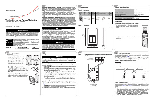
UNITS: inch (mm)
WARNING
Proper Field Wiring and Grounding Required! All field wiring MUST be performed by qualified personnel. Improperly installed and grounded field wiring poses FIRE and ELECTROCUTION hazards.To avoid these hazards, you MUST follow requirements for field wiring installation and grounding as described in NEC and your local/state electrical codes. Failure to follow code could result in death or serious injury.
2.95 (75.0)
0.65 (16.6)
3 Product Specifications
Power supply Power consumption Operating temperature range Operating humidity range Communication Maximum communication length Maximum quantity of controllable devices
2 Pre-installation
Table 1. Components
Remote Cable Cable M4X16 User
U
control tie clamp screw manual Installation terminal
Teledyne Test Tools T3AFG200 T3AFG350 T3AFG500

Debug with Confidence200 MHz – 500 MHzTeledyne Test Tools T3AFG200 / T3AFG350 / T3AFG500 range of function/arbitrary generators are a series of dual-channel waveform generators with specifications of up to 500 MHz maximum bandwidth, 2.4 GSa/s maximum sampling rate and 16-bit vertical resolution. The proprietary Arbitrary & Pulse techniques used in the T3AFG200 / T3AFG350 / T3AFG500 models helps to solve the weaknesses inherent in traditional DDS generators when generating arbitrary, square and pulse waveforms. With the above advantages the T3AFG200 / T3AFG350 / T3AFG500 generators can provide users with a variety of high fidelity and low jitter signals, which can meet the growing requirements of a wide range of complex applications.Tools for Improved Debugging●Deep Memory – 20 Mpts/Ch. G enerate complex arbitrary waveforms.●Wide Range of Modulation Types – AM, DSB-AM, FM, PM, FSK, ASK, PWM, Sweep, Burst, and PSK. Q uickly set up modulated waveforms.●High Resolution – 16 bit resolution. G enerate waveforms with low noise, low spurious signal content and high dynamic range. ●Bandwidth Models up to 500 MHz. W ide choice of bandwidths.●Built In Arbitrary Waveforms. L oad and replay built in Arbitrary Waveforms. ●PRBS, I/Q and user Defined Waveform capability. S upport for complex applications.●Single and dual channel models also available, starting from 5 MHz. I nquire about the T3AFG5, T3AFG10, T3AFG40, T3AFG80 and T3AFG120.Key Specifications2FunctionT3AFG200, T3AFG350, T3AFG500Excellent Performance●Bandwidths from 200 MHz to 500 MHz ●All Models have 2 Channels ●20 Mpts/Channel memoryGreat Connectivity●USB host port for mass storage ●USB device port (USBTMC) ●LAN port on 2 channel modelsThe rise/fall times can be set independently to a minimum of 1 ns (2 ns on T3AFG200) at any frequency and to a maximum of 75 s.The T3AFG range of Function/Arbitrary Waveform Generators support a wide range of modulation types including AM, FM, PM, FSK, ASK, PSK, PWM and DSB-AM.Burst mode supports ‘N Cycle’ and ‘Gated’ modes with the Burst source being configured as ‘Internal’, ‘External’ or ‘Manual’.Output amplitude into a high impedance load can be as high 20 Vpp depending on frequencyand waveform type.Ordering Information3Smart Capabilities●Sweep output carrier can be Sine, Square, Ramp and Arbitrary waveforms. Linear or Log sweep. ●Burst output under internal or external signal control ●Waveforms types include PRBS (PRBS3 – PRBS32) ●Frequency Resolution 1 µHz●DSB-AM: Double Sideband AM modulation Function ●10 Order Harmonic Function ●Optional IQ Modulation (T3AFG-IQ)●Multi-Language User InterfaceThe counter functionality, accessed via the rear panel BNC, gives a DC or AC coupled counter capability from 100 mHz to 400 MHz.The Teledyne Test Tools T3AFG200, T3AFG350 and T3AFG500, with its low jitter design, can generate waveforms with exceptional edge stability. With better jitter performance comes better edge stability, and higher confidence in your circuit design.Sweep mode supports ‘Linear’ and ‘Log’ sweep, with ‘Up’ and ‘Down’ direction, and Sweep sourcecan be configured as ‘Internal’, ‘External’ or ‘Manual’.High Fidelity output with 80 dB dynamic range. Sine wave non-harmonic spurious artifacts are-60 dBc ≤ 350 MHz and -55 dBc > 350 MHz.4Gaussian noise with adjustable bandwidth up to 500 MHz, depending on model. Wide bandwidth Gaussian noise can be added to other waveforms to simulate real-world scenarios in which the signal contains a large degree ofnoise.The T3AFG200, T3AFG350 and T3AFG500 optionally supports IQ signal generation with symbol rates between 250 Symbols/s to 37.5 MSymbols/s, providing ASK, PSK, QAM, FSK, MSK and multi-tone signals.The built-in quadrature modulator provides the possibility to generate IQ signals from baseband to 500 MHz intermediate frequency (depending on T3AFG model).The EasyIQ software is necessary to generate an IQ waveform when using the T3AFG-IQ option.The EasyIQ software is a PC program used to download IQ baseband waveform data to the T3AFG200, T3AFG350 or T3AFG500 through a USB or LAN device interface.T3AFG-IQ, Optional IQ Signal GenerationPhase Locked Operation ModeThe ‘Phase-Locked’ mode automatically aligns the phases of each output. While ‘Independent’ mode permits the two output channels to be used as twoindependent waveform generators.5The T3AFG200, T3AFG350 and T3AFG500 havewaveform combining capability whereby Channel 1 and Channel 2 can be combined to a user selected output. The combined waveform can be output on both Ch 1 and Ch 2 simultaneously, or just on a single output,Waveform CombiningCh 1 or Ch 2, whilst the other channel outputs the un-combined waveform for that channel. Easily combine basic waveforms (sine, square, ramp, pulse, etc), random noise, modulation signals, burst signals and Arb waveforms.The harmonics function gives the user the ability to add higher-order elements to the signal being generated.Harmonic FunctionThe PRBS capability gives the flexibility to generate PRBS waveforms from PRBS3 to PRBS32 at up to 300 Mbps with edge rates from 1 ns to 1 µs. An added differential mode provides an easy way to generatePRBSdifferential PRBS signals using both output channels. Easily set outputs to common logic levels such as TTL, ECL, LVCMOS, LVPECL and LVDS using built-inpresets.616 Bit Resolution●T3AFG200 / T3AFG350 / T3AFG500 are all16 bit resolution●4 x higher resolution than 14 bit systems ●Lower levels of Harmonic Distortion●Lower levels of non-harmonic spurious signals ●Improved dynamic range ●Enhanced signal fi delityI/O Connectivity●LAN and USB connection●10 MHz Reference Input and Output●The Aux Input/Output BNC Connector supports the Trigger Input, Trigger/Sync Output,external modulation input, external sweep/burst trigger input and external gate input ●External Counter input14 Bit Resolution 16 Bit Resolution14 Bit ResolutionLess accurate w aveform generation78910Ordering information11© 2020 Teledyne Test Tools is a brand and trademark of Teledyne LeCroy Inc. All rights reserved. Specifications, prices, availability and delivery subject to change without notice. Product brand or brand names are trademarks or requested trademarks of their respective holders.T3 stands for Teledyne Test Company ProfileTeledyne LeCroy is a leading provider of oscilloscopes, protocolanalyzers and related test and measurement solutions thatenable companies across a wide range of industries to designand test electronic devices of all types. Since our foundingin 1964, we have focused on creating products that improveproductivity by helping engineers resolve design issuesfaster and more effectively. Oscilloscopes are tools used bydesigners and engineers to measure and analyze complexelectronic signals in order to develop high-performancesystems and to validate electronic designs in order to improvetime to market.The Teledyne Test Tools brand extends the Teledyne LeCroyproduct portfolio with a comprehensive range of testequipment solutions. This new range of products deliversa broad range of quality test solutions that enable engineersto rapidly validate product and design and reduce time-to-market. Designers, engineers and educators rely on TeledyneTest Tools solutions to meet their most challenging needs fortesting, education and electronics validation.Location and Facilities Headquartered in Chestnut Ridge, New York, TeledyneTest Tools and Teledyne LeCroy has sales, service anddevelopment subsidiaries in the US and throughoutEurope and Asia. Teledyne Test Tools and Teledyne LeCroyproducts are employed across a wide variety of industries,including semiconductor, computer, consumer electronics,education, military/aerospace, automotive/industrial, andtelecommunications.Teledyne LeCroy (US Headquarters)700 Chestnut Ridge Road Chestnut Ridge, NY. USA 10977-6499 Phone: 800-553-2769 or 845-425-2000Fax Sales: 845-578-5985Phone Support: 1-800-553-2769Email Sales: *******************************Email Support: ************************** Web Site: /Teledyne LeCroy (European Headquarters)Teledyne LeCroy GmbH Im Breitspiel 11c D-69126 Heidelberg, Germany Phone: +49 6221 82700Fax: +49 6221 834655Phone Service: +49 6221 8270 85Phone Support: +49 6221 8270 28 Email Sales: *******************************Email Service: *******************************Email Support: t ********************************Web Site: /germanyWorld wide support contacts can be found at:https:///support/contact/#Distributed by:24july20。
T3破解无线路由密码过程详解(硬盘版

BT3破解无线路由密码过程详解(硬盘版)现在用无线路由的很多,小区里随便搜索一下就能好几个无线信号,不过大部分都是加密的,本教程的目的是破解这些加密的信号,前提必须是用wep 加密的,其实绝大多数都是wep加密的。
由于wap(非wep)加密的破解起来比较困难,成功率很低,故在此暂不讨论。
而wep加密的只要你的无线网卡能够被bt3支持,那么基本上10分钟左右(甚至更快)就能破解一个。
这篇帖子是以装在硬盘上为例进行介绍的====基本思路=====在Windows系统中安装BT3(linux)到D盘;重启后从双启动菜单选择进入BT3操作系统;在BT3中运行Spoonwep这个程序破解无限AP的密码。
====基本条件=====1. 笔记本或台式机(必须有wifi网卡,而且必须能被bt3支持);注:目前701/900/900HA等机型的无线网卡均支持BT3破解,这几款的无线网卡型号好像是Athero 5007EG。
901和1000H好像目前都不支持破解,因为之前我从网上找到了1000H的无线网卡在bt3中的驱动模块,能成功驱动起来,但只支持监听,不支持注入,所以无法破解到密码。
2. 能够在你的周围搜索到无线信号,而且是用wep加密的(本文只讨论wep加密的破解,至于wap加密的暂不讨论);3. 如果无线路由有客户端,也就是有人在用这个路由的信号上网,那么破解起来要快一些;如果没有客户端的话,也可以破解,不过要慢一些。
====软件准备=====软件准备:本文用EeePC900HA(无线网卡:Athero 5007EG)为例做说明,采用硬盘安装bt3的方式(安装到D盘)(U盘安装BT3的方法参见:/redirect.php?tid=16670)。
1. BT3(BT3是linux的一种,好比REDLINUX,好比红旗LINUX。
不过这个BT3集成了大量的黑客工具,尤以破无线网的工具而出名。
)BT3光盘版下载地址:http://ftp.heanet.ie/mirrors/backtrack/bt3-final.iso如果上面的链接你无法下载,你可以自己百度或者迅雷搜索,网上很多这个资源的。
一、单项选择题(在每小题的四个备选答案中,选出一个正确答案,...

一、单项选择题(在每小题的四个备选答案中,选出一个正确答案,并将其序号填在题干的括号内,多选、不选或错选均不得分。
每小题1分,共20分)1.对同一问题所提的意见越新奇独特,则其思维的( )越高。
A.流畅性B.变通性C.独创性D.结构性2.表现出对外在权威的绝对尊敬和顺从的愿望阶段是( )。
A.自我中心阶段B.他律道德阶段C.可逆性阶段D.公正阶段3.心理辅导的目标有两个:一是( ),二是寻求发展。
A.行为矫正B.学会适应C.克服障碍D.学会调适4.力求成功者的目的是获取成就,所以他们最有可能选择的是成功概率为( )的任务。
A.20%B.30%C.50%D.70%5.共同要素理论的代表人物是( )。
A.桑代克B.贾德C.苛勒D.布鲁纳6.( )即操作者自身以外的人和事给予的反馈,有时也称结果知识。
A.内部反馈B.外部反馈C.动觉反馈D.过程反馈7.在群体压力下成员有可能放弃自己的意见而采取与大多数人一致的行为,这就是( )。
A.集体观念B.从众C.服从大局D.群体凝聚8.反馈在操作技能学习过程中的作用是非常关键的,其中( )的作用尤为明显。
A.外部反馈B.方法反馈C.过程反馈D.结果反馈9.加里培林最早对( )进行系统研究。
A.操作技能B.心智技能C.体育技能D.能力技能10.有时学习者为了加深对知识的理解,经常提出一系列的问题,这样的学习策略属于( )。
A.元认知策略B.精细加工策略C.组织策略D.复述策略11.从整体来看,小学生品德发展的关键年龄大致在( )。
A.二年级(8岁左右)B.三年级(9岁左右)C.四年级(10岁左右)D.五年级(11岁左右)12.创造活动的源动力是( )。
A.需要B.兴趣C.好奇心D.理想13.( )强调学习的主动性和认知结构的重要性,所以主张教学的最终目标是促进学生对学科结构的一般理解。
A.苛勒B.桑代克C.布鲁纳D.斯金纳14.以教师为主导的教学策略是( )。
A.指导教学B.发现教学c.情境教学D.合作学习15.( )的课堂气氛是恬静与活跃、热烈与深沉、宽松与严谨的有机统一。
T3价格表(新价格)

3站点 业务通 6站点 10站点 11-及以上站点: 1站点 3站点 存货核算 6站点 10站点 11-及以上站点: 老板通 票据通 跨账套查询 出纳通 1站点 2-及以上站点: 1站点 1-及以上站点: 1-及以上站点: 1站点 3站点 网上银行 6站点 10站点 11-及以上站点: 财务通普及版账表出 纳 财务通普及版存货核算 财务通普及版网上银行
业务管理
1站点 1站点 1站点
1-20站点:
T3普及版
企管通业务管理
企管通业务管理
购销管理 库存核算 财务管理 普及账表
12800元 6800元 1-20站点: 6800元 11800元 3800元 2800元 ([点数]-1)*3000元
企管通财务管理
专业账表 现金银行-出纳 票据打印
1-1站点: 2-3站点: 财务包 4-6站点: 7-10站点: 11-及以上站点: 1-1站点: 2-3站点: 软件包 财务增强包 4-6站点: 7-10站点: 11-及以上站点: 1-1站点: 2-3站点: 财务业务一体包 4-6站点: 7-10站点: 11-及以上站点:
T3系列报价单
产品线 模块名称 站点用户价格
1站点 3站点 总账(含出纳1站点) 6站点 10站点 11-及以上站点: 1站点 3站点 报表 6站点 10站点 11-及以上站点: 工资 1站点 3-及以上站点: 1站点 3-及以上站点: 1站点 2-及以上站点: 1站点
8800元 12800元 16800元 22800元 ([点数]-10)*1800+22800元 2200元 5000元 8000元 11000元 ([点数]-10)*1500+11000元 2200元 6800元 2200元 [点数]*0+6800元 2000元 5800元 12800元 19800元 28800元 38800元 ([点数]-10)*2000+38800元 4800元 7800元 12800元 16800元 ([点数]-10)*1800+16800元 2880元 5000元 2000元 ([点数]-1)*800+1980元 [点数]*2000元 4000元 9000元 11000元 13000元 ([点数]-10)*500+13000元 4980元 3280元 4000元
t3编码方案修改

T3编码方案修改1. 引言在通信领域中,T3编码方案是一种用于数字信号传输的线路编码方案。
然而,在某些特定需求和场景下,对T3编码方案进行修改是必要的。
本文将介绍如何对T3编码方案进行修改,以满足不同的需求和场景。
2. T3编码方案概述T3编码方案是一种基于二进制编码的线路编码方案,用于将数字信号转换为可在传输介质上传输的电子信号。
T3编码方案使用三个电压级别表示二进制数据,即0、+V和-V。
在传输过程中,T3编码方案使用差分编码技术来提高抗干扰性能。
3. T3编码方案修改的需求在实际应用中,可能会遇到一些特定的需求,需要对T3编码方案进行调整。
下面列举了一些常见的需求情况:•需要增强抗干扰性能:在一些噪声环境或干扰严重的情况下,T3编码方案的性能可能会受到影响。
因此,需要对编码方案进行修改,以提高其抗干扰性能。
•需要增加容错能力:在信号传输过程中,可能会出现一些传输错误或信号损失的情况。
针对这些情况,需要对T3编码方案进行修改,以增加其容错能力。
4. T3编码方案的修改方法为了满足不同的需求和场景,可以采取以下方法对T3编码方案进行修改:4.1 增强抗干扰性能为了增强T3编码方案的抗干扰性能,可以考虑以下几个方面的修改:•增加差分编码的级数:增加差分编码的级数可以提高编码方案对干扰的抵抗能力。
通过增加差分编码的级数,可以提高数据传输的稳定性和可靠性。
•引入前向纠错编码:前向纠错编码是一种通过添加冗余数据来纠正传输错误的编码方式。
将前向纠错编码引入到T3编码方案中,可以有效提高编码方案的抗干扰能力。
4.2 增加容错能力为了增加T3编码方案的容错能力,可以考虑以下几个方面的修改:•引入重复编码:在传输过程中,可以对数据进行重复编码,以增加数据的冗余度。
通过引入重复编码,可以提高编码方案对数据传输错误的容错能力。
•增加纠错码技术:纠错码是一种通过引入冗余数据来纠正传输错误的编码方式。
通过引入纠错码技术,可以在数据传输过程中实现错误的检测和纠正,从而提高编码方案的容错能力。
2014年3月公共英语三级考试真题及答案

2014年3月公共英语三级考试真题及答案 SECTION I Listening Comprehension (略) SECTION Ⅱ Use of English ( 15 minutes) Directions: Read the following text. Choose the best word or phrase for each numbered blank and mark A, B,C, or D on your ANSWER SHEET. In the United States today, families basically have two contrasting attitudes toward television. Many families 26 the television to be on at any time of the day or night. Very often, 27 of these families watch television 28 or don' t interact with other family members 29 they are watching. The TV is used to make 30 kind of background noise in the house, 31 as a kind of electronic babysitter. Parents often turn it on to 32 "bored" children. In contrast, other families 33 control when the television will be watched and what programs can be watched. 34 these families watch programs together and discuss them together. In these homes, the TV is rarely on 35 nobody is watching it. Parents don't use it as an electronic babysitter; 36 they insist that children read or play 37 rather than sit in front of a screen. 38 the contrasting attitudes toward television 39, families in America are choosing television 40 other passive activities, such as watching movies, playing video games, and surfing the Web 41 regularity that has never happened before. These activities are 42 in their inactivity. Family members--young and old--watch rather than 43. These passive forms of entertainment 44 , rather than encourage, family 45 and community involvement. 26. [A] allow [B] enable [C] cause [D] require 27. [A] parents [B] members [C] seniors [D] children 28. [ A ] singly [ B ] loosely [ C ] flexibly [ D ] directly 29. [ A ] which [ B ] while [ C ] whereas [ D ] wherever 30. [ A ] little [ B ] such [ C ] some [ D ] this 31. [A] or [B] and [C] thus [D] so 32. [ A ] enlighten [ B ] entertain [ C ] move [ D ] manage [ D ] manage 33. [ A ] effectively [ B ] strictly [ C ] unwillingly [ D ] widely 34. [ A ] Never [ B ] Hardly [ C ] Seldom [ D ] Often 35. [A] if [B] even if [C] so [D] so that 36. [ A ] however [ B ] instead [ C ] moreover [ D ] therefore 37. [A] separately [B] quietly [C] creatively [D] actively 38. [ A ] Because of [ B ] In place of [ C ] In spite of [ D ] Speaking of 39. [A] viewing [R] educating [C] broadcasting [D] programming 40. [ A ] among [ B ] despite [ C ] and [ D ] as 41. [A] with [B] by [C] for [D] over 42. [ A ] usual [ B ] common [ C ] same [ D ] similar 43. [ A ] sleep [ B ] sit [ C ] eat [ D ] do 44. [ A ] weaken [ B ] end [ C ] avoid [ D ] worry45. [ A ] building [ B ] interaction [ C ] planning [ D ] reunion SECTION Ⅲ Reading Comprehension (40 minutes) Part A Directions: Read the following three texts. Answer the questions on each text by choosing A, B, C or D. Mark your answers on your ANSWER SHEET. Text 1 Nisaburo and Hiroko Ohata are unlike most Japanese couples their age. Sure,Hiroko,58, is worried about her husband' s high blood pressure, while Nisaburo,60, promises his wife that if she loses 18 pounds they' 11 take a trip abroad. What makes the Ohatas different is how they met, through a matchmaking organization for single seniors. " On the second date, he asked if I wanted to meet his family," says Hiroko. "I took that as a proposal. " A little rushed, perhaps, but 17years after his wife' s death, Nisaburo knew he' d found a new wife. The couple just celebrated four years of marital happiness last month. In the past, people like Nisaburo and Hiroko might have chosen to live out their lives alone. But as Japan' s society ages, attitudes about love and remarriage late in life are changing. In 2006,according to government data, three times more men and nearly five times more women in their 60sand 70s married for at least the second time, compared with 20 years before. Granted, change is slow. For this silver-haired population, the concept of "dating" is still masked by the term ocha nomi tomodachi (friends having tea together). And older people often need help meeting prospective mates. That' s where specialized matchmaking services such as Ai Senior--" Love Senior"--come in. When Shunichi lkeda started the online service three years ago, he was surprised by how many visits he was getting from people in their 60s. Ikeda says that his clients have an "American perspective" about the dating scene. And their children are often very supportive, sometimes being the ones to register parents. "More older people are realizing that life is supposed to be enjoyable--not lonely," says Ikeda. About 17% of the matchmaking clients in Japan are over 50 years old, according to Ai Senior, and seniors' market share has more than doubled over the past three years. "For older, single men, even doing laundry or cooking is difficult," says Ikeda. "They want to live with a woman. Likewise, it can be boring for women living alone. They want to provide for someone. " 46. According to the writer, the Ohatas are different from most senior Japanese couples in that______ [A] they remarried with the help of an agency[B] they decided to marry on the second date[C] the husband suffers from a health problem[D] the wife is concerned about losing weight 47. As is implied in the text, Nisaburo' s proposal on the second date might be considered______ [A] typical of single seniors [B] irresponsible to his family [C] a surprise to the woman [D] a decision made in haste 48. In Japan, the change in attitudes about remarriage results from an increase in [A] its population [B] single women______ [C] senior people [D] the divorced 49. According to Ai Senior, the matchmaking clients in Japan______ [A] admire the American lifestyle [B] are mostly under 50 years of age [C] share a vague term for "dating" [D] doubled over the past three years 50. According to Ikeda, more single seniors remarry in order to______ [A] live a longer life [B] solve financial problems [ C ] make their life enjoyable [ D ] support their children together Text 2 When you become a parent, much of your focus shifts from your own future to your kids' future. But one of the most effective ways to help your children learn to dream big is to ensure that your own dreams don' t get pushed aside by everyday demands. Our everyday experiences provide learning opportunities. When you tap into them, you create a lifelong learning habit that will always keep you growing. Even your most disappointing experiences can be turned into breakthroughs. Every dream begins in the imagination. Take a few minutes to sit down with a notebook and think about where you would like to be in 20 years. Write down details about all aspects of your ideal life. Feel free to imagine. Don' t worry about whether you know how to get there now—you have 20 years to figure that out. You can also start by picking a year in the future and making a collection of things you' d like in your life by then. Check in on it from time to time to see where you've made progress. We're often encouraged to work on our weaknesses, but working on your strengths is easier and creates better results. For help of identifying them, ask some friends, or colleagues to write down what they most appreciate about you. They' ll enjoy doing this, and you' 11 feel great when you read the responses. Once you know your strengths, you can put them to work to help you achieve your dreams. Confidence is the foundation for all your other abilities. "Progress, notperfection" is a great saying to keep your confidence high. Every night, write down five achievements that happened that day. Big or small, it doesn' t matter. If proper, add ideas for further progress and actions you can take to get started. Find ways to add what you love to do to your life now. This will give you more energy and keep you connected with your bigger dreams. Making a list of old hobbies is a great way to restore your old passions. Things you' re enthusiastic about come with their own store of energy. Connecting with them can give you a push when you most need it. 51. In order to help your children to dream big you must______ [ A] fulfill everyday tasks [ B ] build your own career [C] keep your own dreams [ D] make them look ahead 52. The writer suggests that, to begin your big dream, you should______ [A] stretch your imagination [ B ] have a best-laid plan for 20 years [ C ] recollect all your likes and dislikes [D] engage yourself in lifelong learning 53. According to the writer, to achieve our dreams, we should______ [ A] work on our strengths [ B ] develop our creativity [ C ] identify our weaknesses [ D ] seek advice from friends 54. To keep high confidence, it is important for one to______ [ A ] take appropriate actions [ B ] notice his daily progress [ C ] try his best in everything [ D ] form new ideas every day 55. The writer thinks that one can hold fast to his dream by______ [ A ] listing the details of his ideal life [B] improving some of his old hobbies[C ] adding new ideas to his old dreams [ D ] energizing himself with old passions答案 第一部分听力(略) 第二部分英语知识运用 参考译文 如今,美国家庭对于电视基本上存在着两种对立的态度。
Group Lasso with Overlap and Graph Lasso
Laurent Jacob LAURENT. JACOB @ MINES - PARISTECH . FR Mines ParisTech – CBIO, INSERM U900, Institut Curie, 26 rue d’Ulm, Paris cedex 05, F-75248 France Guillaume Obozinski1 GOBO @ STAT. BERKELEY. EDU INRIA – Willow Project-Team, Ecole Normale Supérieure, 45 rue d’Ulm, Paris cedex 05, F-75230 France Jean-Philippe Vert JEAN - PHILIPPE . VERT @ MINES - PARISTECH . FR Mines ParisTech – CBIO, INSERM U900, Institut Curie, 26 rue d’Ulm, Paris cedex 05, F-75248 France
Abstract
We propose a new penalty function which, when used as regularization for empirical risk minimization procedures, leads to sparse estimators. The support of the sparse vector is typically a union of potentially overlapping groups of covariates defined a priori, or a set of covariates which tend to be connected to each other when a graph of covariates is given. We study theoretical properties of the estimator, and illustrate its behavior on simulated and breast cancer gene expression data.
BH系列电动机说明书

1/750 HP1 W 1/125 HP6 W 1/50 HP15 W 1/30 HP25 W 1/19 HP40 W 1/12 HP60 W 1/8 HP90 W1/19-1/8 HP 40-90 W(2-Pole)Induction Motors BH Series200 W (1/4 HP)Frame Size: Ⅺ4.09 in.(Ⅺ104 mm sq.)ⅥFeatures●BH Series motors provide 200W output power and up to 530 lb-in (60 N•m) of torque in a compact 4.09 in. sq. (104 mm sq.) mounting configuration.●Right-angle gearheads are available.●For easy installation, the BH Series motor and gearhead come pre-assembled.✻Motors and gearheads are also available separately.ⅥProduct LineⅷCombination Type◆Right-Angle Shaft◆Parallel Shaft●Enter the gear ratio in the box (Ⅺ) within the model name.●Enter the gear ratio in the box (Ⅺ) within the model name.T: Contains a built-in thermal protector. If a motor overheats for any reason, the thermal protector is opened and the motor stops.When the motor temperature drops, the thermal protector closes and the motor restarts. Be sure to turn the motor off before inspecting.●Details of Safety Standard➝Page G-2●Enter the gear ratio in the box (Ⅺ) within the model name.●The values in the table are for the motor only.(Cable Type,Right-Angle Hollow Shaft)(Terminal Box Type,Parallel Shaft)(Terminal Box Type,Right-Angle Solid Shaft)A-54System Configuration A-15Features A-14Specifications A-54A-55Dimensions A-57Connection Diagrams A-63List of Motor and Gearhead Combinations A-64AC MotorsInduction Motors Synchronous MotorsTorque Motors Watertight Motors Magnetic BrakeClutch &BrakeBrake PackReversible Motors Right-AngleGearheads AccessoriesIntroductionBefore Using a Standard AC MotorⅷRound Shaft Type●Enter the gear ration in the box (Ⅺ) within the model name. A colored background indicates gear shaft ration in the same direction as the motor shaft; a white background indicates rotation in the opposite direction.●Decimal gearheads are not available for the BH Series.●The speed is calculated by dividing the motor's synchronous speed (50 Hz: 1500 r/min, 60 Hz: 1800 r/min) by the gear ratio. The actual speed is 2ϳ20% less than the displayed value, depending on the size of the load.ⅥPermissible Overhung Load and Permissible Thrust LoadMotor (Round shaft type) ➝Page A-11Gearhead ➝Page A-11ⅥPermissible Load Inertia J for Gearhead➝Page A-12v Single-Phase 230 VAC 50 HzⅷParallel ShaftⅥGearmotor — Torque TableⅷRight-Angle Shaftv Single-Phase 115/230 VAC 60 Hz, Three-Phase 230 VAC 60 HzUnit סUpper Values: lb-in/Lower Values: N •m Unit סUpper Values: lb-in/Lower Values: N •m Unit סUpper Values: lb-in/Lower Values: N •mUnit סUpper Values: lb-in/Lower Values: N •m1/750 HP1 W 1/125 HP6 W 1/50 HP15 W 1/30 HP25 W 1/19 HP40 W 1/12 HP60 W 1/8 HP90 W1/19-1/8 HP 40-90 W(2-Pole)ⅥMounting Method for Hollow Shaft GearheadsⅷStepped-Down ShaftⅷStraight Load ShaftThese diagrams show how to mount loads depending on theshape of the shaft.The tolerance of the inner diameter for the hollow shaft isfinished as H8, and "key slot" processing is given to mountthe load shaft. The recommended tolerance of the load shaftis h7. Apply a coating of molybdenum disulfide or similargrease to the inner diameter of the load shaft to preventbinding. Recommended load shaft dimensions are shownbelow.●Replace the safety cover after installing the load shaft.Note:●Be careful not to apply a shock to the hollow shaft when mounting a load. It maydamage the bearing inside the gearhead.Recommended size of inner diameter for thehollow shaft and load shaftA-56System Configuration A-15Features A-14Specifications A-54A-57Connection Diagrams A-63List of Motor and Gearhead Combinations A-64Induction Motors Synchronous MotorsTorque MotorsWatertight Motors MagneticBrakeClutch &BrakeBrake Pack Reversible Motors Right-Angle Gearheads AccessoriesIntroduction Before Usinga Standard AC MotorⅥDimensions Scale 1/4, Unit = inch (mm)Mounting screws are included with the combination type parallel shaft.➝Page A-223Enter the gear ratio in the box (Ⅺ) within the model name.◆Combination Type Right-Angle, Hollow Shaft Cable TypeBHI62F-ⅪRH, BHI62E-ⅪRHWeight: 22 lb. (10.0 kg) including gearhead Motor Model: BHI62F-G2, BHI62E-G2Gearhead Model: BH6G2-ⅪRH d A299ⅷKey (Included) (Scale 1/2)1/750 HP1 W 1/125 HP6 W 1/50 HP15 W 1/30 HP25 W 1/19 HP40 W 1/12 HP60 W 1/8 HP90 W1/19-1/8 HP 40-90 W(2-Pole)◆Combination Type Right-Angle, Solid Shaft Cable Type BHI62F-ⅪRA, BHI62E-ⅪRAWeight: 22 lb. (10.0 kg) including gearheadMotor Model: BHI62F-G2, BHI62E-G2Gearhead Model: BH6G2-ⅪRAdA300Ϫ.1ⅷKey and Key Slot (Included) (Scale 1/2)∗At the time of shipment, a parallel key is inserted on the gearhead's shaft.A-58System Configuration A-15Features A-14Specifications A-54A-59Connection Diagrams A-63List of Motor and Gearhead Combinations A-64Induction Motors Synchronous MotorsTorque MotorsWatertight Motors Magnetic BrakeClutch &BrakeBrake PackReversible Motors Right-Angle Gearheads AccessoriesIntroductionBefore Usinga Standard AC MotorGearhead Model: BH6G2-ⅪRH d A301ⅷKey (Included) (Scale 1/2)ⅷUse cable (VCTF ) with a diameter of 0.24 inch (6 mm)ϳ0.47 inch (12 mm).ⅷDetails of Terminal Box ➝ Page A-2241/750 HP1 W 1/125 HP6 W 1/50 HP15 W 1/30 HP25 W 1/19 HP40 W 1/12 HP60 W 1/8 HP90 W1/19-1/8 HP 40-90 W(2-Pole)Gearhead Model: BH6G2-ⅪRAdA302Ϫ.1ⅷKey and Key Slot (Included) (Scale 1/2)∗At the time of shipment, a parallel key is inserted on the gearhead's shaft.ⅷUse cable (VCTF) with a diameter of 0.24 inch (6 mm)ϳ0.47 inch (12 mm).ⅷDetails of Terminal Box ➝Page A-224A-60System Configuration A-15Features A-14Specifications A-54A-61Connection Diagrams A-63List of Motor and Gearhead Combinations A-64Induction Motors Synchronous MotorsTorque MotorsWatertight Motors Magnetic BrakeClutch &Brake Brake Pack Reversible Motors Right-Angle Gearheads AccessoriesIntroductionBefore Using a Standard AC Motor◆Combination Type, Parallel Shaft Type Cable TypeBHI62F-Ⅺ, BHI62E-ⅪWeight: 18 lb. (8.0 kg) including gearhead Motor Model: BHI62F-G2, BHI62E-G2Gearhead Model: BH6G2-Ⅺd A3030Ϫ0.1ⅷKey and Key Slot (Included) (Scale 1/2)∗At the time of shipment, a parallel key is inserted on the gearhead's shaft.◆Combination Type, Parallel Shaft Type with Terminal BoxBHI62FT-Ⅺ, BHI62ET-Ⅺ, BHI62ST-ⅪWeight: 18 lb. (8.0 kg) including gearheadMotor Model: BHI62FT-G2, BHI62ET-G2, BHI62ST-G2Gearhead Model: BH6G2-Ⅺd A304Ϫ0.1ⅷKey and Key Slot (Included) (Scale 1/2)∗At the time of shipment, a parallel key is inserted on the gearhead's shaft.ⅷUse cable (VCTF ) with a diameter of 0.24 inch (6 mm)ϳ0.47 inch (12 mm).ⅷDetails of Terminal Box ➝ Page A-2241/750 HP1 W 1/125 HP6 W 1/50 HP15 W 1/30 HP25 W 1/19 HP40 W 1/12 HP60 W 1/8 HP90 W1/19-1/8 HP 40-90 W(2-Pole)◆Round Shaft Type Cable TypeBHI62F-A, BHI62E-AWeight: 11 lb. (5 kg)◆Round Shaft Type with Terminal BoxBHI62FT-A, BHI62ET-A, BHI62ST-AWeight: 11 lb. (5 kg)d A308ⅷCapacitor (Included with single-phase motors)●If you need to order a capacitor without a motor, add "-C" to the capacitor model name shown. A capacitor cap is included with a capacitor.●Enter the gear ratio in the box (Ⅺ) within the model name.Conductors: UL Style 3271, AWG 20ⅷUse cable (VCTF) with a diameter of 0.24 inch (6 mm)ϳ0.47 inch (12 mm).ⅷDetails of Terminal Box ➝Page A-224A-62System Configuration A-15Features A-14Specifications A-54A-63Dimensions A-57Connection Diagrams A-63List of Motor and Gearhead Combinations A-64AC MotorsInduction Motors SynchronousMotorsTorqueMotorsWatertight Motors Magnetic BrakeClutch &Brake Brake Pack Reversible Motors Right-Angle Gearheads Accessories Introduction Before Using a Standard AC MotorⅥConnection Diagrams●The direction of motor rotation is as viewed from the shaft end of the motor.●CW represents the clockwise direction, while CCW represents counterclockwise direction.✽1Enter F or E (power supplyvoltage) in the box (Ⅺ) within the model name.✽2Connecting to the terminal block for terminal box typeApplicable lead wire: AWG 24ϳ12(0.2 mm 2ϳ4.0 mm 2)Strip length: 0.31 inch (8 mm)Note :●Change the direction of single-phase motor rotation only after bringing the motor to a stop. If an attempt is made to change the direction of rotation while the motor is rotating, the motor may ignore the reversing command or change its direction of rotation after some delay.●To protect the contact point of switches, connect a CR circuit.Connecting CR circuit, contact capacity ➝Page A-226●For increased safety, provide a breaker or fuse on the power-supply input.●How to Connect a Capacitor ➝Page A-225ⅷInner Connection Diagram for 4-Terminal CapacitorT erminals of the capacitor are connected as shown in the figure. For lead wire connection, use one lead wire per terminal.1/750 HP1 W 1/125 HP6 W 1/50 HP15 W 1/30 HP25 W 1/19 HP40 W 1/12 HP60 W 1/8 HP90 W1/19-1/8 HP 40-90 W(2-Pole)ⅥList of Motor and Gearhead CombinationsⅷCombination Type Right-Angle Shaft●Enter the gear ratio in the box (Ⅺ) within the model name.ⅷCombination Type Parallel Shaft●Enter the gear ratio in the box (Ⅺ) within the model name.A-64System Configuration A-15Features A-14Specifications A-54。
SINUMERIK SINUMERIK 840D sl 前置操作面板:OP 015A 设备手册 06

1.4 1.4.1 1.4.1.1 1.4.1.2 1.4.1.3 1.4.1.4 1.4.2 1.4.2.1 1.4.2.2 1.4.2.3 1.4.2.4 1.4.2.5 1.4.2.6 1.4.2.7 1.4.2.8 1.4.2.9 1.4.2.10
联网................................................................................................................................40 系统设置.........................................................................................................................40 采用 SINUMERIK solution line 时的设置........................................................................40 设备网络中的系统启动....................................................................................................42 精简型客户端单元(TCU)............................................................................................43 出厂预设置......................................................................................................................44 调试 TCU........................................................................................................................46 操作 TCU 主菜单............................................................................................................46 操作其他 TCU 菜单.........................................................................................................49 在设备网络中注册 TCU..................................................................................................61 校准触摸面板..................................................................................................................64 连接 SIMATIC Thin Client 触摸面板...............................................................................66 配置 SIMATIC Thin Client 触摸面板...............................................................................67 文件“config.ini”中的设置...............................................................................................69 文件“tcu.ini”中的设置....................................................................................................72 采用 TCU 时的置换机制.................................................................................................79 通过 PLC 禁止 TCU 之间的切换.....................................................................................81
FRENIC-Mini 紧凑型变频器 说明书
危险危险危险危险危险危险键只有在通过功能代码H96不能通过操作面板上的危险危险通信卡的安装,请先将电源断开5分钟以上,再使用测试器等确认主电路端子危险危险*protection (motorInstall UL certified fuses between the power supply and the inverter, referring to the键、键操作。
注意提示目录前言 (i)■安全注意事项 (i)■ 使用注意事项 (x)本书构成 (xiii)第1章 使用前.......................1-11.1 现货的确认...................1-11.2 产品的外观...................1-21.3 搬运.........................1-21.4 保管.........................1-31.4.1 暂时保管.................1-31.4.2 长期保管.................1-3 第2章 安装和配线...................2-12.1 使用环境.....................2-12.2 安装.........................2-12.3 配线.........................2-22.3.1 端子台盖的拆除...........2-22.3.2 端子配置图和螺钉规格.....2-32.3.3 推荐电线尺寸.............2-42.3.4 配线上的注意.............2-62.3.5 主电路端子,接地端子的配线...................2-72.3.6 主电路端子台盖的安装....................2-122.3.7 控制电路端子的配线......2-122.3.8 漏/源(跳线开关)的切换............2-172.3.9 RS485通信卡(选配件)的安装........2-182.3.10 控制电路端子台盖的安装...................2-192.3.11 高次谐波x噪声漏电流的注意事项.......2-20 第3章 用操作面板操作...............3-13.1 操作面板各部分的名称和功能....3-13.2 操作模式概要.................3-23.2.1 运转模式.................3-4[ 1 ] 运转状态的监视.........3-4[ 2 ] 设定频率等的设定.......3-6[ 3 ] 运转x停止操作..........3-9[ 4 ] 电动(寸动)运转.......3-93.2.2 程序模式................3-10[ 1 ] 设定功能代码「数据设定」..........3-12 [ 2 ] 确认变更后的功能代码「数据确认」..........3-15 [ 3 ] 监视运转状态「驱动监视器」........3-16[ 4 ] 检查输入输出信号的状态「I/O 检查」...........3-19 [ 5 ] 查看维护保养信息「维护保养信息」.......3-23 [ 6 ] 查看报警信息「报警信息」...........3-253.2.3 报警模式.................3-28第4章 運転..........................4-14.1 试运转........................4-14.1.1 电源接通前的确认..........4-14.1.2 电源接通及接通后的确认......................4-14.1.3 试运转前的准备-功能数据代码的确认......4-24.1.4 试运转....................4-34.2 運転..........................4-3第5章 功能代码......................5-15.1 功能代码一览表................5-15.2 功能代码的概要...............5-10第6章 发生故障时…..................6-16.1 故障检修前....................6-16.2 无报警代码显示时........................6-26.2.1 电机的异常动作............6-26.2.2 变频器设定操作上的故障......................6-66.3 有报警代码显示时........................6-76.4 有报警代码以外的显示时.......................6-16 第7章 保养检查......................7-17.1 日常检查......................7-17.2 定期检查......................7-17.3 主电路电量的测定..............7-57.4 绝缘试验......................7-67.5 定期更换零部件一览表..........7-77.6 产品的咨询和保证..............7-7第8章 规格..........................8-18.1 标准规格......................8-18.1.1 3相系列(200V)...........8-18.1.2 3相系列(400V)...........8-28.1.3 单项系列(200V)...........8-38.1.4 单项系列(100V)...........8-48.2 准标准规格....................8-58.2.1 EMC滤波内置型............8-58.2.2 制动电阻器内置型..........8-58.2.3 RS485通信对应型..........8-5xiv8.3 通用规格.....................8-68.4 端子规格.....................8-88.4.1 端子功能.................8-88.4.2 基本连接图...............8-88.5 外形尺寸图...................8-98.5.1 标准规个及准标准规格(制动电阻器内置型,RS485通信对应型)........8-98.5.2 准标准规格(EMC滤波器内置型).....8-118.6 保护功能....................8-13第9章 外围设备一览表・选配件一览表.................9-1第10章 直流电抗器的适用...........................10-1第11章 关于标准对应...............11-111.1 关于UL标准及加拿大标准(cUL认定)对应.............11-111.1.1 一般...................11-111.1.2 注意事项...............11-111.2 关于欧洲标准的满足..........11-111.3 关于EMC标准的满足..........11-211.3.1 一般...................11-211.3.2 推荐设置方法...........11-211.3.3 关于EMC滤波器内置型及EMC对应滤波器(选配件)的漏电流......11-411.4 关于欧洲的高次谐波的规制....11-511.4.1 一般...................11-511.4.2 关于对应...............11-611.5 关于欧洲的低电压指令的满足.....................11-611.5.1 一般...................11-611.5.2 注意事项...............11-6xv(a) 额定铭牌 图1.1 铭牌表示 制动关联1 无制动电阻器(标准)2 制动电阻器内置型输入电源3相200V3相400V单相100V单相200V表示 结构S 标准型E EMC 滤波器内置型表示 系列名 FRN FRENIC 系列 表示 标准适用电机容量 表示 适用范围 紧凑型 表示 开发系列 表示 选配件内置 1 无2 RS485通信对应型表示 表示 结构S 标准型(IP20)E EMC 内置形(IP20)2467注)选配件内置:无,制动关联:无制动电阻器(标准)时,根据标准规格,最后2位不显示。
HU269外部检查单
2 构架、前横梁、阻力杆,撬管无变形.......................................无变形3 大气温度传感器无堵塞.................................................................无堵塞4 风挡玻璃清洁、无裂痕....................................................清洁、无裂痕5 整流罩、进气系统、天线、空速管状态好...............................状态好机身左侧6 减震器、航行灯、频闪灯、着陆灯状态好...............................状态好7 滑油排放塞、发动机进、排气管、燃、滑油管路良好..............良好8 区域导线、火花塞固定....................................................................良好9 中部构架接头良好............................................................................良好10 电瓶检查...................................................................................固定良好11 发动机滑油液面检查.............................................................符合要求12 座舱门及门锁良好..........................................................................良好13 顶棚边条检查..................................................................................良好14 桨叶、桨毂、阻尼器、变距拉杆、倾斜盘检查........................良好15 后横梁、发动机输出轴、发电机下皮带轮轴承及叶轮、H框架检查........................................................................................良好16 尾传动轴设定对准标记对准.........................................................对准17 排气管、尾梁撑杆接头检查.........................................................良好18尾梁中下部VOR天线、静压孔检查...........................................良好机身后部19 垂直尾面检查........................................................................状态好20 尾桨叶、倾斜盘、变距拉杆检查...........................................良好21 尾撬、尾灯、尾桨轴对准标记检查.......................................良好22 尾减速器滑油液面检查...................................................符合要求23 水平安定面检查........................................................................良好机身右侧24 尾梁无损伤............................................................................无损伤25 尾传动轴阻尼器、尾梁撑杆接头检查...................................正常26 主减速器滑油液面检查...................................................符合要求27 油箱左侧组合摇臂检查............................................................良好28 惰轮、离合器钢索检查............................................................良好29 尾桨操纵钢索检查....................................................................良好30 油箱加油口盖,通气孔检查...................................................良好31 减震器、航行灯、频闪灯检查...........................................状态好32 进、排气管、各区域导线检查...............................................正常33 中部构架检查............................................................................良好34 座舱门及门锁,顶棚边条检查...............................................良好飞行员飞行前检查路线。
- 1、下载文档前请自行甄别文档内容的完整性,平台不提供额外的编辑、内容补充、找答案等附加服务。
- 2、"仅部分预览"的文档,不可在线预览部分如存在完整性等问题,可反馈申请退款(可完整预览的文档不适用该条件!)。
- 3、如文档侵犯您的权益,请联系客服反馈,我们会尽快为您处理(人工客服工作时间:9:00-18:30)。
2014年3月中国非制造业商务活动指数为54.5% 来源:国家统计局发布时间:2014-04-03 09:00
国家统计局服务业调查中心
中国物流与采购联合会
2014年3月,中国非制造业商务活动指数为54.5%,高于荣枯线4.5个百分点,但比上月回落0.5个百分点。
分行业看,服务业商务活动指数为52.8%,比上月回落1.0个百分点,其中住宿业、批发业、水上运输业、互联网及软件信息技术服务业、电信广播电视和卫星传输服务业等行业商务活动指数位于60%以上的较高景气区间,企业业务总量较快增长;餐饮业、航空运输业、装卸搬运及仓储业、铁路运输业、道路运输业、零售业、生态保护环境治理及公共设施管理业商务活动指数位于临界点以下,企业业务总量减少。
建筑业商务活动指数为61.3%,比上月上升1.4
个百分点,位于较高景气区间。
新订单指数有所回落。
新订单指数为50.8%,比上月回落0.6个百分点,位于临界点以上。
分行业看,服务业新订单指数为50.1%,比上月回落0.4个百分点,其中住宿业、互联网及软件信息技术服务业、水上运输业、批发业、电信广播电视和卫星传输服务业、生态保护环境治理及公共设施管理业等行业新订单指数高于临界点,市场需求有所增加;餐饮业、装卸搬运及仓储业、道路运输业、航空运输业、铁路运输业、房地产业、零售业等行业新订单指数低于临界点,市场需求有所减少。
建筑业新订单指数为53.9%,虽比上月回落1.0个百分点,但继续位于临界点以上,表明建筑业市场需求继续保持增长态势。
中间投入价格指数有所回升。
中间投入价格指数为52.8%,比上月上升0.7个百分点,表明非制造业企业用于生产运营的中间投入价格水平有所上涨。
分行业看,服务业中间投入价格指数为53.4%,比上月上升0.9个百分点,其中铁路运输业、居民服务及修理业、住宿业、装卸搬运及仓储业、水上运输业、道路运输业、批发业、零售业、邮政业、房地产业等行业中间投入价格指数高于临界点,企业运营成本压力有所加大;生态保护环境治理及公共设施管理业、航空运输业、电信广播电视和卫星传输服务业中间投入价格指数低于临界点。
建筑业中间投入价格指数为50.5%,比上月回落0.2个百分点,位于临界点以上,表明建筑业生产经营成本涨幅有所收窄。
收费价格指数继续低于临界点。
收费价格指数虽比上月回升0.5个百分点,但仍位于临界点以下的49.5%,表明非制造业企业的销售或收费价格总体水平有所下降。
分行业看,服务业收费价格指数为49.3%,比上月回升0.8个百分点,低于临界点,其中铁路运输业、住宿业、生态保护环境治理及公共设施管理业、装卸搬运及仓储业、邮政业、互联网及软件信息技术服务业、居民服务及修理业等行业收费价格指数高于临界点;航空运输业、租赁及商务服务业、水上运输业、道路运输业、餐饮业等行业收费价格指数低于临界点。
建筑业收费价格指数为50.4%,虽比上月回落0.7个百分点,但仍高于临界点,企业的销售或收费价格总体水平小幅回升。
业务活动预期指数连续高位回升。
业务活动预期指数为61.5%,比上月上升1.6个百分点,并处于较高景气区间,表明非制造业企业对未来3个月市场预期继续持乐观的态度。
分行业看,仅装卸搬运及仓储业低于临界点,其他行业均位于扩张区间。
中国非制造业PMI分类指数(经季节调整)
单位:%
商务活动新订单中间投入
价格
收费价格
业务活动
预期
2013年3月55.652.055.350.062.4 2013年4月54.550.951.147.662.5 2013年5月54.350.154.450.762.9 2013年6月53.950.355.050.661.8 2013年7月54.150.358.252.463.9 2013年8月53.950.957.151.262.9 2013年9月55.453.456.750.660.1 2013年10月56.351.656.151.460.5 2013年11月56.051.054.849.561.3 2013年12月54.651.056.952.058.7 2014年1月53.450.954.550.158.1 2014年2月55.051.452.149.059.9 2014年3月54.550.852.849.561.5附注:
1.指标解释
中国非制造业PMI指标体系,由商务活动指数、新订单指数、新出口订单指数、在手订单指数、存货指数、中间投入价格指数、收费价格指数、从业人员指数、供应商配送时间指数、业务活动预期指数等10个分类指数构成。
由于没有合成的非制造业综合PMI指数,国际上通常用商务活动指数反映非制造业经济发展的总体变化情况,以50%作为经济强弱的分界点,高于50%时,反映非制造业经济扩张;低于50%,则反映非制造业经济收缩。
2.调查范围
涉及《国民经济行业分类》(GB/T4754-2011)中非制造业的27个行业大类,从全国非制造业企业中抽取1200家样本企业进行调查。
3.调查方法
非制造业采购经理调查采用PPS(Probability Proportional to Size)抽样方法,以非制造业行业大类为层,行业样本量按其增加值占全部非制造业增加值的比重分配,层内样本使用与企业主营业务收入成比例的概率抽取。
本调查由国家统计局直属调查队具体组织实施,利用国家统计联网直报系统对企业采购经理进行月度问卷调查。
4.计算方法
非制造业采购经理调查问卷涉及业务总量、新订单(业务需求)、出口、在手订单、存货、中间投入价格、收费价格、从业人员、供应商配送时间、业务活动预期等10个问题。
对每个问题分别计算扩散指数,即正向回答的企业个数百分比加上回答不变的百分比的一半。
5.季节调整说明
采购经理调查是一项月度调查,受季节因素影响,数据波动较大。
目前,我国非制造业PMI时间序列已满足季节调整的技术要求,自2012年3月起发布季节调整后的非制造业PMI分类指数。