armstrong08_basic
爱德华斯传统触发器目录说明书

Page 1 of 4 D A T A S H E E TS85001-0589Not to be used for installation purposes. Issue 2Edwards Signaling Catalog uConventional InitiatingMEARate Compensation Heat Detectors302 SeriesBox mount Surface MountOverviewSeries 302 heat detectors are designed for use in normal environ-ments as well as environments where the detectors are subject to weather, moisture (internal condensation), and explosive atmo-spheres. They are normally-open devices designed to close an electrical circuit upon activation. All models feature rate compen-sation and are available with either 135 °F (57.2 °C) or 194 °F (90 °C) ratings. They are self restoring, hermetically sealed, shock and corrosion resistant, and are tamperproof.Standard Features• Rate compensation offsets thermal lag • Self-restoring – no manual reset required• Explosion proof and weatherproof models available • Weatherproof models available that do not require a special backbox • Box mount and surface mount models availableApplicationSensors rated at 135 °F (57.2 °C) will not respond to momentary temperature fluctuations less than 30 °F/minute between 60 °F (16 °C) and 100 °F (38 °C). Sensors rated at 194°F (90 °C) will not respond to momentary temperature fluctuations less than 50 °F/minute between 60 °F (16 °C) and 150 °F (66 °C). 302 Series sen-sors should not be used in environments where conditions exceed these parameters. Do not install them in hot air ducts, in front of heaters, in paint booths that use heat to cure paint, or any otherlocation subject to temperature fluctuation.194 °F (90 °C)-40 °F (-40 °C)150 °F (66 °C)The sensor's aluminum tube acts as a heat collector when sourc-es of heat radiate directly on the tube. Install these sensors out of direct sunlight and away from radiating heat sources including the direct flow from heaters and heat ducts.Page 2 of 4 D A T A S H E E TS85001-0589Not to be used for installation purposes. Issue 2Typical WiringElectrical Rating6-25 VDC 1 amp 125 VDC0.5 ampMaintenance302 Series heat sensors are low maintenance. Sensors automati-cally restore when temperatures drop below their rated tempera-tures. The accumulation of dust and dirt does not normally affect the sensors’ operation.TestingTesting for operation is simple and can be done before or after the sensor has been installed. Heat the sensor with a hair dryer (do not use any device with an open flame to test sensors). The sen-sor should operate shortly after the hot air is applied.Refer to NFPA 72, National Fire Alarm Code and/or the localauthority having jurisdiction to determine testing frequency, record keeping, and other testing considerations.Rate Compensation302 Series sensors feature rate compensation, which improves performance by offsetting thermal lag, an inherent property of conventional fixed temperature heat sensors.A slow rate of temperature rise allows the heat to penetrate the inner expansion struts. The tubular shell and the struts expand slowly until the total device has been heated to its rated tempera-ture level of 135 °F (57.2 °C) or 194 °F (90 °C). At this point, the silver contact points close and an alarm is initiated.When subjected to a rapid rate temperature rise, there is not as much time for heat to penetrate the inner strut. However, the rapid lengthening of the shell allows the struts to come together at a lower level.When the surrounding air temperature returns to below the rated level, the shell contracts, forcing the contacts to open, thus auto-matically resetting the sensor.Fine silver contact Expansion strutsHigh expansion sensingshell, 0.040 anodized aluminum Heat control sleeve Setting screwDevcon hermetic sealWARNING – Use For Property Protection Only: Heat detectors do not protect life against fire and smoke. In most fires, hazardous levels of smoke, heat and toxic gases can build up before a heat sensor would initiate an alarm. Independent studies indicate that heat sensors should only be used when property protection alone is involved. In cases where life safety is a factor, the use of smoke detectors is recommended.Under no circumstances should heat detectors be relied upon as the sole measure to ensure fire safety. However, if they are spaced in accordance with the specifications found under Application, these sensors can contribute, within an overall fire safety program, to reducing the risk of avoid-able property losses.When used with automatic fire suppression systems such as pre-action and deluge sprinkler systems, carbon dioxide systems, halon systems, and dry chemical systems, at least two sen-sors should be used to initiate the alarm. This is commonly referred to as cross-zoning or prioritymatrix zoning and is necessary to eliminate premature discharge of the system. Refer to NFPA 72 for more information.Detector Spacing(all models)(15.2 x 15.2 m)(15.2 x 15.2 m)(15.2 x 15.2 m)(12.2 x 12.2 m)UL- Horizontal Spacing (all models)40' x 40' (12.2 x 12.2 m)40' x 40' (12.2 x 12.2 m)40' x 40' (12.2 x 12.2 m)30' x 30' (9.1 x 9.1m)FM - Horizontal or vertical spacing.*30' x 30' (9.1 x 9.1m)30' x 30' (9.1 x 9.1m)30' x 30' (9.1 x 9.1m)Not ListedSpacing is based on smooth ceilings that are up to 10' (3 m) high. Refer to NFPA 72 for ceilings that are not considered smooth or are higher than 10' (3 m).* EPM models are not FM approved.DimensionsTube Diameter 0.5" (12.7 mm)0.5" (12.7 mm)NPT Thread 0.5" (12.7 mm)0.5" (12.7 mm)Hex Base1" (25.4 mm) plastic1.25" (31.75 mm)brassOrdering InformationJALX11Explosion proof outlet body with cover (½" thread hubs back, four sides and cover) - Killark 3.5 lb. (1.6 kg)Page 3 of 4D A T A S H E E T S85001-0589Not to be used for installation purposes. Issue 2Contact us...Phone: 1-800-336-4206Web: Edwards Signaling isan EDWARDS brand.3 Farm Glen BoulevardFarmington, CT 06032In Canada, contact Chubb Edwards...Email: **************************Web: © 2013 UTC Fire & Security AmericasCorporation, Inc. All rights reserved.Specifications subject to changewithout notice. Edwards is part of UTCClimate, Controls & Security, a unit ofUnited Technologies Corporation.06-27-13 Page 4 of 4D A T A S H E E T S85001-0589Not to be used for installation purposes. Issue 2。
第2章 Freescale HC(S)08系列单片机概述
第2章Freescale HC08/S08/RS08 MCU概述Freescale的08系列单片机由于其稳定性高、开发周期短、成本低、型号多种多样、兼容性好而被广泛应用。
本章概要介绍08系列单片机的类型、基本结构,并从总体上阐述其性能特点。
主要内容有:在介绍08系列单片机的命名规则和资源状况的基础上,分别以MC908GP32、MC9S08GB60及MC9RS08KA2为例讲述HC08系列、HCS08系列及RS08系列单片机的基本结构和特点。
了解这些基本知识,不仅可以为实际开发应用中的单片机选型提供参考,也对后续章节的学习有很大的帮助。
本书以GP32为主要芯片阐述嵌入式系统基本硬件与软件原理,2.2节讨论的GP32引脚功能、硬件最小系统及GP32的存储器框图是重点掌握的内容。
硬件最小系统是芯片运行的基本条件,应该对此有清晰的理解。
对于GP32不具备的功能,本书将使用其他芯片进行阐述,但编程语言体系是相同的。
2.1 08系列单片机简介目前,Freescale的08系列单片机主要有HC08、HCS08和RS08三种类型。
HC08是1999年开始推出的产品,种类也比较多,针对不同场合的应用都可以选到合适的型号。
HCS08是2004年左右推出的8位MCU,资源丰富,功耗低,性价比很高,是08系列单片机的发展趋势。
HC08与HCS08的最大区别是调试方法不同与最高频率的变化。
RS08是HCS08架构的简化版本,于2006年推出,其内核体积比传统的内核小30%,带有精简指令集,满足用户对体积更小、更加经济高效的解决方案的需求。
RAM及Flash 空间大小差异、封装形式不同、温度范围不同、频率不同、I/O资源差异等形成了不同型号,为嵌入式应用产品的开发提供了丰富的选型。
2.1.1 Freescale单片机的命名规则Freescale单片机的型号庞大,但同一系列的CPU是相同的,也就是说具有相同的指令系统,多种型号只是为了适用于不同的场合。
雷赛BASIC编程手册v2.1
3.2.7 STOP ...............................................................................................................18
3.2.8 AUTO..............................................................................................................18
3.3.1 运算符.............................................................................................................19
3.3.2 ABS.................................................................................................................22
3.2.3 SUB.................................................................................................................17
3.2.4 ON GOSUB ....................................................................................................18
雷赛运动控制器 BASIC 语言编程手册
Version 2.1
ARTISAN技术组合购物指南说明书

User's Guidee-mail: ************** GPIB HARDWARE MANUAL FOR USE WITHPCI-GPIB, ISA-GPIB142.6 CPCI-GPIB (12)2.5 PC104-GPIB (11)2.4.2 Windows 3.1 (11)2.4.1 Windows 95 (10)2.4 PCM-GPIB (8)2.3 ISA-GPIB/LC (6)2.2 ISA-GPIB (5)2.1 PCI-GPIB (5)CHAPTER TWO: INSTALLATION ...................31.2.3 Connection Configurations . (2)1.2.2 GPIB Electrical Signal Configuration (1)1.2.1 Talkers, Listeners, and Controllers (1)1.2 GPIB SYSTEM DESCRIPTION (1)1.1 HISTORY (1)CHAPTER ONE: INTRODUCTION ......................Chapter One: INTRODUCTION1.1 HISTORYThe GPIB (General Purpose Interface Bus) has become the worldwide standard for connecting instruments to computers. Invented in the 1960s by Hewlett Packard and originally designated as HPIB, the bus specification was eventually adopted by a wide variety of both instrument and computer manufacturers. The original specification was documented and sanctioned by the Institute of Electrical and Electronic Engineers as IEEE-488.The advent of the inexpensive and powerful personal computer has driven the GPIB market through explosive growth. As GPIB bus usage expanded, there arose the need for some additional capability and standardization, so in 1987, IEEE-488.2 was adopted. IEEE-488.2 was revised/ammended in 1992 and represents the current GPIB specification. The new specification provides some standardization among compliant instruments. These standardization greatly simplifies the job of the GPIB system designer since 488.2 compliant instruments share common programming conventions.1.2 GPIB SYSTEM DESCRIPTION1.2.1 Talker s, Listeners, and ControllersA GPIB device can be a Talker, Listener, and/or Controller. As the name implies a Talker sends data to one or more Listeners, A Listener accepts data from a Talker and a Controller manages the flow of information over the bus. A GPIB Digital Voltmeter is acting as a Listener as its input configurations and ranges are set, and then as a Talker when it actually sends its readings to the computer.The Controller is in charge of all communications over the bus. The Controller’s job is to make sure only one device tries to talk at a time, and make sure the correct Lis-teners are paying attention when the Talker talks. Each GPIB system has a single sys-tem controller. The system controller is ultimately in charge of the bus, and is in control as the bus is powered up. There can be more than one Controller on the bus and the System Controller can pass active control to another controller capable device, though only one can be Controller In Charge at a given time. TheGPIB board is usually designated as the System Controller.1.2.2 GPIB Electrical Signal Configuration1The GPIB is an 8-bit parallel data transfer bus. In addition to the 8 data bits, the bus carries three handshaking lines and five GPIB specific management and control lines. The remainder of the standard 24 pin GPIB cable is used for the cable shield, signal grounds and returns. The GPIB connector pin-out is shown in the diagram below:Standard GPIB Cable/ConnectorDATA LINESDIO1 through DIO8 are the data transfer bits. Most GPIB systems send 7-bit data and use the eight bit as a parity or disregard it entirely2HANDSHAKING LINESThere are three handshaking lines that control the data transfer between devices.NRFD (Not Ready For Data): this bit is used to indicate the readiness (or lack thereof) of a device to accept dataDAV (Data Valid): bit is used to indicate to receiving devices that data has been placed on the bus and is available to read.NDAC (Not Data Accepted): is asserted by the receiving device to indicate that data has been read and may now be removed from the bus.SYSTEM MANAGEMENT LINESATN (Attention): is used by the controller to specify how data on the DIO lines is interpreted and which devices must respond to the dataIFC (Interface Clear): is used by the system controller to place the entire system in a known quiescent (Cleared) state and to assert itself as Controller In Charge (CIC).SRQ (Service Request): is used by a device on the bus to indicate the need for atten-tion and requests an interrupt of the current event sequence.REN (Remote Enable): is used by the controller in conjunction with other messages to place a device on the bus into either remote or local modeEOI (End or Identify): Is used by Talkers to indicate the end of a message string, or is used by the Controller to command a polling sequence.1.2.3 Connection ConfigurationsThe GPIB specification is quite definitive regarding the number of devices and cable lengths allowed in a GPIB system. There can be no more than 15 devices on a single contiguous GPIB bus. Larger systems are possible by installing additional GPIB inter-face boards in your computerThe maximum, total length of all cables on a single GPIB system is 20 meters. In addition, cable length between consecutive devices may be no greater than 4 meters, and average cable length must be 2 meters or less. Stated another way, the total cable length (in meters) in the system may not be longer than 2 times the number of devices (up to 20 meters). Longer length systems are possible, but only with the use of a GPIB extender card.In addition to the above rules, at least two thirds of all devices on the bus should be powered on for proper operation.3Keeping the above constraints in mind, there is no limitation on the actual connection scheme used to connect the GPIB devices together. Star, Linear or any combination of both may be used. These are shown in the following diagrams.4,QVWUXPHQW &,QVWUXPHQW ',QVWUXPHQW $,QVWUXPHQW %Linear C onnectionC onfiguration ,QVWUXPHQW ',QVWUXPHQW &,QVWUXPHQW (,QVWUXPHQW $,QVWUXPHQW %S tar C onnectionC onfigurationChapter Two: INSTALLATION The following sections describe the hardware installation procedure for GPIB boards. After hardware installation, please refer to your GPIB software installation guide for additional setup and operation details.2.1 PCI-GPIBThe PCI-GPIB board is completely plug and play. To install this board into your sys-tem follow the simple steps shown below.1. Turn your computer off2. Open your computer case3. Insert the PCI-GPIB into any available PCI slot4. Put your computer’s case back on.5. Turn your computer back on, and follow the instructionsin the GPIB software manual you received with your board.52.2 ISA-GPIBThe only hardware configuration required prior to installing the ISA-GPIB/LC is set-ting the board’s Base Address switch. The location of the Base Address switch is shown in the photograph above, while the switch itself is shown in the diagram on the following page.Most computers will have Base Address 300 Hex (768 decimal) free and the default setting of the board is 300 Hex. If there is already a board in your system using address 300 HEX (768 Decimal), you will have to change the board’s base address prior to installing it in your computer. Other typically free addresses include 310 Hex and 330 Hex.6The following diagram shows the base address in its default 300 Hex setting.987 6 5 4S V65LThe address values corresponding to each of the switches are shown in the following table.Hex Dec.Switch Value Value Default9 200 512 up (200 Hex)8 100 256 up (100 Hex)7 80 128 down (0 Hex)6 40 64 down (0 Hex)5 20 32 down (0 Hex)4 10 16 down (0 Hex)-----------------total 300 HexNote: On this base address switch, Up is on, Down is off. This con-figuration is the opposite of most ISA baseddata acquisition boards.72.3 ISA-GPIB/LCThe following diagram shows the base address in its default 300 Hex setting.987654S V65LThe address values corresponding to each of the switches are shown in the following table.Hex Dec.Switch Value Value Default9200512up (200 Hex)8100256up (100 Hex)7 80128down (0 Hex)6 40 64down (0 Hex)5 20 32down (0 Hex)4 10 16down (0 Hex)-----------------total300 HexNote: On this base address switch, Up is on, Down is off. This con-figuration is the opposite of most ISA based data acquisitionboards.92.4 PCM-GPIBThe installation procedure is different for Windows 95 and DOS/Windows 3.1. These procedures are described below:10:LQGRZVThe PCM-GPIB board is completely plug and play. There are no switches or jumpers to set prior to installation in your computer. Simply follow the steps shown below to install you PCM-GPIB hardware. Once your hardware is installed, please refer to the GPIB-488.2 software manual.1. Start Windows 952. Insert the card into a free PC Card/PCMCIA slot. You do not have toturn the computer off. The system is designed for power on installation.3. Windows 95 will automatically detect the card and depending on theversion of Windows 95 you have, you will either see a New HardwareFound dialog box or a Update Device Driver Wizard box.4. Insert PCM-GPIB Disk 1 into your A drive and follow the instructionsprovided by the dialog box/wizard..If no New Hardware Found dialog box appears, check that you computer’s 32-bit PCMCIA drivers are enabled. This can be checked using the following Windows 95 sequence. Start>Settings>Control Panel>System and look in Performance section. It should read 32-bit. If not, enable 32-bit, shut down your computer and try the above procedure again.:LQGRZVMost users are now installing boards on systems with at least Windows 95 operating systems. However, if you wish to install the PCM-GPIB board in a machine running Windows 3.1 and/or DOS, you will need to use the DOS based Card & Socket serv-ices routine. This is included with most newer computers. However, if you need to purchase these routines, they are available as part number PCM-C&SS from Com-puterBoards for a nominal price. To run the C&SS installation routines, place the PCM-C&SS disk in drive a:, from your boot drive (usually C:) type A:Install and hit enter. Then simply follow the instructions on your screen.The PCM-GPIB hardware is completely plug and play. There are no switches or jumpers to set prior to installation in your computer. Once your hardware is installed, please refer to the GPIB-488.2 software manual.112.5 PC104-GPIBThe only hardware configuration required prior to installing the ISA-GPIB/LC is set-ting the board’s Base Address switch. The location of the Base Address switch is shown in the photograph above, while the switch itself is shown in the diagram on the following page.Most computers will have Base Address 300 Hex (768 decimal) free and the default setting of the board is 300 Hex. If there is already a board in your system using address 300 HEX (768 Decimal), you will have to change the board’s base address prior to installing it in your computer. Other typically free addresses include 310 Hex and 330 Hex.12The following diagram shows the base address in its default 300 Hex setting.987654S V65LThe address values corresponding to each of the switches are shown in the following table.Hex Dec.Switch Value Value Default9200512up (200 Hex)8100256up (100 Hex)7 80128down (0 Hex)6 40 64down (0 Hex)5 20 32down (0 Hex)4 10 16down (0 Hex)-----------------total300 HexNote: On this base address switch, Up is on, Down is off. This con-figuration is the opposite of most PC104 based data acquisitionboards.132.6 CPCI-GPIBThe CPCI-GPIB board is completely plug and play. To install this board install this board into you system follow the simple steps shown below.1. Turn your computer off2. Open your computer front panel (if enclosed)3. Insert the CPCI-GPIB into any available 3U CPCI slot4. Put your computer’s case back on (optional).5. Turn your computer back on, and follow the instructionsin the GPIB software manual you received with your board.14EC Declaration of ConformityDescriptionPart Number Computer to GPIB interface Computer to GPIB interface Computer to GPIB interface Computer to GPIB interface Computer to GPIB interface Computer to GPIB interface ISA-GPIBISA-GPIB/LCPCI-GPIBPC104-GPIBPCM-GPIB CPCI-GPIBto which this declaration relates, meets the essential requirements, is in conformitywith, and CE marking has been applied according to the relevant EC Directives listedbelow using the relevant section of the following EC standards and other normativedocuments:EU EMC Directive 89/336/EEC : Essential requirements relating to electromagneticcompatibility.EU 55022 Class B : Limits and methods of measurements of radio interferencecharacteristics of information technology equipment.EN 50082-1: EC generic immunity requirements.IEC 801-2: Electrostatic discharge requirements for industrial process measurementand control equipment.IEC 801-3: Radiated electromagnetic field requirements for industrial processmeasurements and control equipment.IEC 801-4: Electrically fast transients for industrial process measurement and controlequipment.Carl Haapaoja, Director of Quality Assurance。
飞思卡尔半导体 如何在M68HC08、HCS08和HCS12 微控制器上应用IIC模块 说明书

飞思卡尔半导体文件编号:AN3291 应用笔记第1版,03/2007Specifications and information herein are subject to change without notice. ©Freescale Semiconductor,Inc., 2007. All rights reserved.General Business Information如何在M68HC08、HCS08和HCS12微控制器上应用IIC模块作者: Stanislav Arendarik应用工程师捷克共和国,罗斯诺夫1 简介此应用笔记是如何在飞思卡尔的微控制器上应用IIC模块的一个示例。
IIC模块可以分别在主模式或从模式下使用。
在这种情况下,由于IIC 总线主要用于在微控制器(MCU)和IIC外设之间的通信,因此在主模式时与串行EEPROM进行通信。
IIC总线可以在两个微控制器(MCU)之间直接进行通信,然而SPI总线却更适用于这种应用。
此应用笔记总结了通用IIC总线状态和定义,并提供了如何与串行EEPROM进行通信的示例(24C16和24C512)。
您可以轻松地用另外一个IIC器件取代EEPROM,但是必须改变将其标识为从器件的IIC地址字节。
目录1 简介…………… . . . . . . . . . . . . . . . . . . . . . . . .. . . . . . . . . . . . . . . 12 IIC 总线摘要………….. . . . …. . . . . . . . . . . . . . . . . . . . . . . . . . . . 22.1 IIC总线术语.. . . . . . . . . . . . . . . . . . . . . . . . . . . . . . . . . . . . . 22.2 位传输. ………….. . . . . . . . . . . . . . . . . . . . . .. . . . . . . . . . . . 22.3 起始条件和停止条件(START and STOP Conditions)...... . 32.4 总线通信. . ……………………….. . . . . . . . . . . . . . . . . . . . 32.5 控制字节………………………. . . . . . . . . . . . . . . . . . . . .. . . 32.6 地址字节……….... . . . . . . . . . . . . . . . . . . . . . . . . . . . . . . . . 42.7 应答………… . . . . . . . . . . . . . . . . . . . . . . . . . . . . . . . .. . . . 42.8 读/写格式………………………………......…..…... . . . . . . .. 53 用于微控制器的IIC软件程序. ………. . . . . . . . . . . . . . . . . . . . . . . 53.1 IIC的初始化. … . . . …….. . . . . . . . . .. .. . . . .. .. .. . . . . . . . 63.2 写入功能. . . . . . . . . . . . . . . . . . . . . .. . . . . . .. . . . . . . . . . . 73.3 读取功能 .. . . . . . . . . . . . . . . . . . . . .. . .. . . . . .. . . . . . . . . 93.4 中断应用举例. . . . . . ……………. . . . . . . . . . . .. . . . . . . . . 133.4.1 MCU作为主机.. . . . . . . . . . . .. .. . . . . . . . . . . . . . . 133.4.2 MCU作为从机. . . . . . .. . . . . . . .. . . . . . .. . . . . . . 164 结论. . . ……... . . . . . . . . . . . . . . . . . . . . . . . . . . .. . . .. . . . . . . .. . . 17IIC总线摘要2 IIC 总线摘要IIC总线是基于主机和从机间线与(开漏)连接的双向、两线式总线。
4个公司的8脚单片机简单介绍
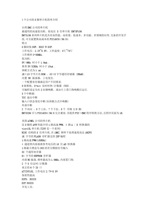
美国 ATMEL 公司的单片机 仅 8 脚的 AVR 性能介绍 1 路高速 PWM、4 路 A / D 转换器的 tiny15L 单片机(TINY 是一个系列) RISC 结构的 8 位单片机,在 1MHZ 频率下处理速度高达 1MIPS 1K 字节的 FLASH 存贮器支持 ISP 编程 1 路高速 PWM(150KHz) 4 通道带内部基准参考电压的 10 位 AD 转换器 1 路最大增益为 20X 的差分模拟信号输入 32 个通用寄存器 64 字节的 EEPROM 存贮器 内部 RC 振荡,频率最高为 1.6MHz,内部看门狗. 2 个 8 位定时/计数器 真正的 6 个 IO 口 ATTINY15L 工作电压 2.7V-5.5V 保密性能高 DIP8、SOIC8 DIP/SOIC8 开发工具:
4 个公司的 8 脚单片机简单介绍
台湾 EMC 公司的单片机 最通用的高速低功耗、低电压 8 位单片机 EM78P156 EM78156 系列单片机是具有高性能、高质量、低成本、多功能、多领域的应用.完备的开发手 段,可全面置换高成本的 PIC16C54/56/84. 特点 8 脚封装 SOP、SOIC 和 DIP. 工作电压: 2.2V~5.5V、工作温度: 0℃~70℃ 工作频率 C-36MHz. 低功耗: 5V/4MHz 时小于 1.6mA . 典型 3V/32KHz 时小于 15uA . 休眠方式为 1 uA . 1K×13 字节片内 ROM 、48×8 字节通用存储器 (SRAM). 内置 RC 振荡器、上电复位. 一个配置寄存器满足用户不同要求. 5 级堆栈、8-bit 实时时钟/计数器 (TCC) . 可编程设定为从 I/O 脚唤醒、或由片上看门狗唤醒后运行. 3 个中断源: TCC 溢出中断 输入口状态变化中断(从休眠方式中唤醒) 外部中断 2 个双向 、8 个上拉、7 个下拉、8 个 开路 I/O 脚. EM78X56 可与 PIC16C54/56/8 完全兼容,并提供 PIC→EMC 程序转换方法,且程序页面为 1K.
安装说明-Compact 5000 I O 数字量 8 点安全拉出型输入模块说明书

安装说明Compact 5000 I/O 数字量 8 点安全拉出型输入模块目录号 5069-OBV8S 、5069-OBV8SKThe 5069-OBV8S 和 5069-OBV8SK 模块是 8 点安全拉出型输入模块。
这些模块在安全控制网络上提供满足以下要求的安全 I/O ,该等要求包括 SIL CL3 和 PLe, Cat. 4,如 IEC 61508、IEC 61511、IEC 62061 和 ISO 13849-1 中所规定。
该模块提供拉出型输出和双极性类型输出。
您可将 Compact 5000™ I/O 安全模块用作带 CompactGuardLogix®5380 控制器的本地和远程 I/O 模块,以及带 Compact GuardLogix 5380 和 GuardLogix 5580 控制器的远程 I/O 模块。
5069-IB8SK 模块提供与 5069-IB8S 模块相同的功能,但具有保形涂层,有助于在恶劣环境中提供保护。
使用 Studio 5000 Logix Designer® 软件配置模块。
Compact GuardLogix 5380 和 GuardLogix 5580 控制器必须使用 32.011 或更高的固件版本,才可使用 Compact 5000 I/O 安全模块。
Compact 5000 I/O 安全模块采用生产者/消费者通信模式。
生产者/消费者通信模式是模块与其他系统设备之间的一种智能数据交换,在通信过程中,每个模块都会生成数据,而不是先被轮询。
有关如何使用 Compact 5000 I/O 模块的更多信息,请参见第12页的其他资源中列出的出版物。
变更摘要主题页码关于模块5安装系统5安装可拆卸端子块7安装模块8安装终端盖9对可拆卸端子块进行接线9断开电线与可拆卸端子块之间的连接9使用束线带10为系统供电10拆卸模块10技术参数11其他资源12主题页码删除接线图有关如何连接模块的信息,请参阅中第12页的其他资源列出的出版物不适用Compact 5000 I/O 数字量 8 点安全拉出型输入模块ATTENTION:Read this document and the documents listed in the Additional Resources section about installation, configuration and operation of this equipment before you install, configure, operate ormaintain this product. Users are required to familiarize themselves with installation and wiring instructions in addition to requirements of all applicable codes, laws, and standards.Activities including installation, adjustments, putting into service, use, assembly, disassembly, and maintenance are required to be carried out by suitably trained personnel in accordance with applicable code of practice.If this equipment is used in a manner not specified by the manufacturer, the protection provided by the equipment may be impaired.注意:在安装、配置、操作和维护本产品前,请阅读本文档以及“其他资源”部分列出的有关设备安装、配置和操作的相应文档。
880 870螺纹钢管诊断仪说明书
Installation & Instruction Manual
Safety Information
Important – Please Read Before Installation
J Flow Controls 880 / 870 Series Diaphragm Actuator instructions contain Danger, Warning and Caution labels, where necessary, to alert you to safety related or other important information. Read the instructions carefully before installing and maintaining your control valve. Danger and Warning hazards are related to personal injury. Caution hazards involve equipment or property damage. Operation of damaged equipment can, under certain operational conditions, result in degraded process system performance that can read to injury or death. Total compliance with all Danger, Warning and Caution notices is required for safe operation. The safety terms Danger, Warning, Caution and Note have used in these instructions to highlight particular dangers and/or to provide additional information on aspects that may not be readily apparent.
腾龙2008智能型编程器使用说明.

腾龙2008智能型编程器使用说明隆重推出腾龙2008智能型编程器,采用电子开关电路取代跳线操作,操作变得更简单、更直接、更稳定。
腾龙2008同样继承本站超越飞越系列特点最大兼容。
支持所有的主板bios芯片、打印机复印机控制芯片、超值增加对PIC系列芯片的全面支持。
采用超线程MCU设计编程速度再次提高60%写入一片8M的芯片仅需要2分钟。
腾龙2008硬件版本为万用硬件版本的独特设计,全面兼容老版本和新版等等的硬件结构,独具时空切换功能,大家再也不会因为不清楚自己用的是什么硬件版本而发愁了。
独具时空切换的功能,可以同时支持PCB3控制软件和最新版控制软件,有些网友可能会感到奇怪,腾龙2008为什么要支持老的软件?原因其实很简单,因为新版软件0.99E,0.99E+等对W27C512和A T28C64B(程序存储器芯片,常用的单片机程序存储外置)等等芯片的支持的没有老版的98系列软件稳定,比如经典的97JA软件在烧写W27C512的成功律能达到100%,另外需要注意的一点是,站长本人在制作ICD2的过程中发现,0.97Ja烧写PIC16F877A的可靠性也是最一流的,而0.99e反倒不如0.97Ja那样完美,但是对于烧写BIOS芯片而言,0.98D2,0.98E等要更快一些。
腾龙2008编程器更新:硬件增加了对编程器过载保护、芯片插反保护、短路保护、软写入模式、电路。
采用3个微动开关选择编程电压,从此不再需要去记忆繁琐的跳线。
软件采用0.99E烧写芯片的速度提高30%。
腾龙2008编程器支持所有的主板BIOS芯片、独家提供对内存SPD芯片、彩电显示器EPROM芯片、打印机复印机控制芯片的完美支持。
唯我忠于维修级编程器开发,腾龙2008编程器于其他网站设计的编程器不同,我们的产品定位在计算机芯片级维修行业,不论是硬件设计还是软件都遵循实用性第一的方针,腾龙2008编程器是一款专业的维修设备。
彻底抛弃DC供电,采用单USB供电设计,工作更稳定专业设计的升压电路可将USB供电提升至35V。
罗克韦尔自动化 Micro800 可编程控制器系列选型指南说明书

Micro800 可编程控制器系列Bulletin 2080、20852罗克韦尔自动化出版物 2080-SG001G-ZH-P - 2022 年 11 月Micro800 可编程控制器系列 选型指南罗克韦尔自动化认识到,目前我们行业和本出版物中使用的一些条款不符合技术中包容性语言的发展趋势。
我们正积极与行业同行合作,寻找此类条款的替代方案,对产品和内容进行更改。
在我们尚未完成实施这些更改之前,请不要使用我们内容中的这些条款。
目录最新产品本出版物中包含以下新增内容或更新信息。
该列表仅列出了主要更新,并未反映出所有变更。
并非每次修订都提供有翻译版本。
主题页码最新产品2Micro800 控制器概述3Micro800 控制器比较4选择 Micro810 控制器8选择 Micro820 控制器9选择 Micro830 控制器10选择 Micro850 控制器11选择 Micro870 控制器12选择 Micro800 扩展 I/O 模块13选择 Micro800 功能性插件模块和附件14其他资源17主题页码添加了有关支持 Kinetix 5100 和 PowerFlex 520 系列变频器用于固件版本为 21.011 或更高版本的 Micro850 (2080-L50E) 和 Micro870 (2080-L70E) 控制器的信息3在 Micro800 产品目录输入/输出数量和类型表中添加了以太网节点列6在 Micro850 产品目录输入/输出表中添加了以太网节点列11、12在 Micro870 产品目录输入/输出表中添加了以太网节点列13罗克韦尔自动化出版物 2080-SG001G-ZH-P - 2022年 11 月3Micro800 可编程控制器系列 选型指南Micro800 控制器概述Micro800™ 控制器设计用于经济型单机控制。
根据基座中内置 I/O 点数的不同,这些经济的小型可编程逻辑控制器 (PLC)具有不同的配置,其拥有的一系列特性足以满足不同的需求。
Basic Training

NS series 內部
ASEKH-Test
Horizontal Mounting Handler
Synax141HC:
可用於三(常、高、低)溫測試,廠內主要用於低溫測試 適用於大部分Tray包裝的產品 此機台只有Single Site Change Kit 可由CAD組設計、製造
Synax141-內部
MCT
Daymarc-717
ASEKH-Test
3. Change Kit / Conversion Kit
Change Kit: 自動測試機台用檢治具
➢安裝於Handler內。 ➢主要功能用來加熱、定位及傳送測試產品,故需依據測試產 品的種類、大小選擇適用之Change Kit。 ➢依Handler種類的不同,大致主要組件如下:
因應手動測試或驗正的需求,一般設計有可拆裝之手測 蓋 Lid(Manual Actuator) 。
Pogo-Pin Socket
含手測蓋-vertical view
含手測蓋-lateral view
ASEKH-Test
Pogo-Pin Socket:
Socket / Contactor
ASET Socket
3.MT9510 / Delta Handler Kit 目前正在建立Change Kit設計能力中
ASEKH-Test
Capability of Change Kit
1. Package Size Limitation: 4mm x 4mm(smallest) 2. Package Type: BGA / BCC / QFN / QFP / PLCC 3. Handler Kit Design Capability: NSxxxx / Synax /
小学上册第二次英语第3单元期末试卷

小学上册英语第3单元期末试卷英语试题一、综合题(本题有100小题,每小题1分,共100分.每小题不选、错误,均不给分)1.What kind of animal is an octopus?A. MammalB. FishC. ReptileD. MolluskD2. (Revolutionary) War was fought for American independence. The ____3.The puppy is very _____ (cute/scary).4.Which animal can swim and fly?A. FishB. BirdC. DuckD. DogC5.Which animal is known as the "King of the Jungle"?A. LionB. TigerC. BearD. ElephantA6. A __________ is a reaction that involves a change in color.7.The ________ was a major conflict fought in the 20th century.8.I have a big collection of _____ (乐高) bricks.9.The chemical formula for carbon dioxide is ________.10.My aunt loves __________ (参与新活动).11.local action network) connects residents for collaborative efforts. The ____12.The boy likes to play ________.13.I look forward to seeing my ____.14.They are ___ (singing/playing) together.15.I like to run in the _____ (公园).16.What is the term for a written account of someone's life written by someone else?A. BiographyB. MemoirC. AutobiographyD. NovelA17.The __________ (历史的多元) enriches perspectives.18. A __________ is a large area of natural wonder.19.What do we call the science of studying living things?A. PhysicsB. ChemistryC. BiologyD. AstronomyC20.We are going to the ___. (fair) this weekend.21.She is wearing ___. (glasses)22. A frog can leap very ______ (远) to catch insects.23.__________ are found on the right side of the periodic table.24.The _____ (芦荟) is good for the skin.25.What is the main ingredient in sushi?A. RiceB. BreadC. NoodlesD. PotatoesA26.What is the largest organ in the human body?A. HeartB. LiverC. SkinD. Brain27.The chemical formula for potassium nitrate is _______.28.The cake is _____ (sweet/sour) and tasty.29.I see a _____ bird in the tree. (yellow)30.The __________ is a layer that protects life on earth.31.The __________ (历史的真相) may be difficult to uncover.32.The sky is _____ (clear/cloudy) today.33.My favorite fruit is ________ (草莓).34.What do plants need to grow?A. WaterB. CandyC. ToysD. MusicA Water35.The main source of energy for the Earth is the _______.36.The ancient Greeks created many famous ______ (戏剧)。
EBS Reidmar 502 专业巴斯头部说明书
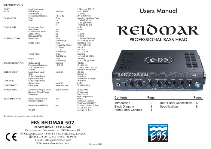
EBS REIDMAR 502PROFESSIONAL BASS HEADD ESIGNED AND D EVELOPED BY EBS S WEDEN AB G RINDSTUVÄGEN 44-46,SE-16733B ROMMA ,S WEDEN+4687350010,F AX :+4687350005E-MAIL :*(******************WEB:Users ManualPROFESSIONAL BASSHEADREIDMARINPUT:GAIN:CHARACTER:COMP/LIMIT:FILTER SECTION:BALANCED OUTPUT:EFFECT LOOP:LINE OUT:PHONES OUT:POWER AMP:AUXILIARY INFO:Input Impedance 2Mohms //100pF Gain Range min/max -oo/+30dB Gain Peak LED+10dBvFrequency Response +0/-3dB 20-20.000HzFilter:Type Shelving High/Low Pass Gain:Lo +7dB @40Hz Mid -2dB @800Hz Hi+3dB @10kHz Compressor Gain 0dB Attenuationmax 24dB Compression Ratio max 3:1Attack (80%)typ <10ms Release (80%)typ 100msBass Filter:Type12dB/oct.Shelving Gain Range +/-18dB @60Hz Middle Filter:TypeBandpass Filter Frequency Range 100-6.000Hz Q -Boost 0.7-1.1Q -Cut0.8->10Gain Range +/-12-15dB Treble Filter:TypeShelvingGain Range +/-18dB @6kHz Bright:TypeShelvingGain Range +15/-0dB @10kHz Output LevelNominal -10dBv Frequency Response +0/-3dB 10-20k HzXLR Connections 1-GND,2-Hot,3-Cold OptionsGND Lift,Pre/Post EQ Loop Signal Level nominal-10dBv GainUnity (1:1)Output Impedance 100ohmsInput Impedance >50kohms //100pF Output Impedance 100ohms Signal Level nominal0dBvImpedancerecommended 32-200ohmsContinuous Output Power @2or 4ohms250W RMS Dynamic Output Power 470W peak ProtectionShort circuit,High temperature Power Requirements max 500WMains Protection:T2.5A Fuse (230V)T5A Fuse (100/120V)Dimensions (WxDxH)max33cm x 25cm x 7.5cm 13”x 9.8”x 3.0”Weight:3.3kg (7.3lbs.)Specifications are subject to change without notice!SPECIFICATIONSNovember 2018Contents:Page:Introduction 2Block Diagram3Front Panel Controls4Page:Rear Panel Connections 6Specifications8INTRODUCTION27Welcome to the EBS Reidmar Bass Head!The EBS Reidmar provides a full bodied,warm and transparent tone throughout the entire range.It is equipped with EBS renowned built in compressor,professional balanced XLR-output,Character filter and an efficient 4-Band EQ that lets you master the sound.The Reidmar does not compromise on the tone,it uses and benefits from all the 250Watts RMS,without getting muddy or clipping,giving a powerful and highly portable amp with an impressive tone that will handle any stage or studio session gig.The EBS Reidmar handles a minimum of 2Ohm load and is the perfect companion to a stack of Mini size ClassicLine or NeoLine cabinets,or used with a single full size EBS cabinet.The Reidmar amp is designed and developed in the heart of Sweden by EBS.GETTING STARTED...1.Carefully unpack the bass head.2.Check that all knobs are set fully counter clockwise besides the EQ controls marked BASS,MIDDLE and TREBLE which should be set to mid position.Make also sure all push switches are set to their outer positions.Now the EBS Reidmars settings are "zeroed"and ready to be personalized.3.Connect one or more speaker cabinets to the speaker output.Make sure the total impedance is not below 4ohms.4.Turn on the POWER switch.5.Plug in your bass.While plucking the strings as hard as you would during your hardest playing,gradually increase the GAIN knob unit the peak LED starts to flash at peaks.6.Move over to the VOLUME knob and adjust for the desired output volume.BUILDING THE SOUND...7.The first tonal shaping circuitry is thenext to the GAIN control.This filters provides a preshape EQprior of further fine tuning of your sound.8.Enable the filters by pressing the pushbutton and explore the filter section.Play your bass.Note that there isn't any difference in sound yet.9.The filters are basically of the boost/cutdesign.This means that the level controls marked with +and -signs,either boost or cuts the selected frequency band.Further,the MIDDLE section has got a frequency control for precise adjustment of the midrange.10.Gradually increase or decrease the level andvary the frequency of the middle filter when operating the middle filter.Notice how the sound is effected.An A/B comparison can be made by toggling the filter active switch.11.Proceed to the COMP/LIMIT knob.This controladjusts the compression and is useful when playing very dynamic or loud.12.Turn up the COMP/LIMIT knob to mid and maxposition.Notice how the peaks in volume will straighten out as you play harder and harder.13.Now,go on to the BRIGHT and turn it half wayup.Play your bass.The BRIGHT filter is a high pass filter which works on the highest fre-quencies of the bass to give enhanced ambiance and presence.Character Filter Filter Active This was a brief introduction and as you go on further in this manual,you will learn how to use and utilize all of the useful features that the offers you.EBS Reidmar GOOD LUCK !F UNCTIONAL D ESCRIPTION R EAR P ANEL :146235BALANCED OUTPUT GND LIFT SWITCH PRE/POST EQ SWITCH -A balanced output functions as a high quality line box for connecting to PA mixing consoles or to studio or broadcast recording units,with high noise immunity.The volume level does not effect this output.-Lifting ground is a great aid in many occasions eliminating ground noise and hum.When required,set this switch to position to disconnect the ground from the balanced output.-The setting sends the signal after the and sections to the balanced output.The setting outputs the signal after the entire preamp.Lift Pre Post Gain Character EFFECTS LOOP –This is a serial effects loop for the use of external units such as box or rack effects.Nominal level is set for use with standard stomp boxes.The loop puts the external effects after the filter and compressor sections.LINE OUT -This is a fullrange output that will drive multiple poweramps,extending the power of the system.The signal present at this output is taken after the volume control.PHONES -Connect standard headphones to this output.This output automatically mutes the internal poweramp and line output LINE OUT when connected.7891011SPEAKER OUTPUT SYSTEM FAN MAINS MAINS SELECTOR SWITCH POWER –Connect your speakers here.Care should be taken when connecting speakers so that the minium total impedance is not lower than 2ohms.–The amps performance is maintained among other techniques with a fan controlling the temperature of the unit.–Connect only to the indicated mains AC voltage and replace fuse if needed only with same type and value.-Selects the operating mains voltage.-Switches the amp on or off.Note:Lower impedance than 2ohms may cause permanent damage to the amp.EBS will not take responsibility for eventual hearing damages caused by the powerful EBS Reidmar.Make sure not to cover the ventilation openings of the amp!IMPORTANT!Unplug the amp before selecting the mains voltage!REAR PANEL DESCRIPTION3FRONT PANELCONTROLSBright Bass +Treble7VOLUME -The VOLUME knob controls all volume in the unit,controlling the poweramp and LINE output.The balanced output (XLR)is not affected by the setting of this knob.8PILOT LAMP -Indicates power on condition.BLOCK DIAGRAM645The LED intensity dynamically indicates the amount of compression during play.–This switch actives the filter section described under point 6.-The filter section contains four enhanced performance filters:is a 'shelving'type 12dB/oct slope phase compensated bass filter with a wide gain range.is a shelving type filter controlling the higher mids and treble registers,giving presence and ambience to the sound.is an advanced high pass filter capable of producing bright high treble timbre,without adding practically any noise.FILTERACTIVE FILTERS BASS MIDDLE TREBLE BRIGHT has an extended frequency range of 100-6000Hz.This filter facilitates total control over the mids,with a wide bandwidth giving a natural and non-peaking result using frequency dependent gain.In addition,at minimum setting this filter facilitates a notch function,suitable for cutting an exact frequency or eliminating acoustic coupling.56BassMidrangeTrebleFRONT PANEL CONTROLS13456872F UNCTIONAL D ESCRIPTION F RONT P ANEL C ONTROLS :INPUT CHARACTER FILTER -A low noise,high impedance instrument input that will interface with passive and active instruments perfectly.-The EBS Reidmar provides a preshape filter,,which operate independently from the other preamp functions.This gives the user the opportunity to preshape the sound before the final processing with the other features of the preamp.When pressed to inner position,boost is achieved in bass and treble ranges respectively,while the midrange has a slight drop in gain.Character 13GAIN COMP/LIMIT -Control to adjust the instruments'signal strength to the right operating level in the EBS Reidmar.For optimum basic signal level,turn up the GAIN knob until the PEAK led starts flashing from the strongest signal from the instrument.-A low noise compressor limiter that works fast and effectively,tightening up the sound and preventing the bass head from saturating at peaks when approaching the headroom limit.A string may be plucked very hard and fast,without any greater difference in level or side effects.The COMP/LIMIT knob sets the compression ratio,i.e.The signal strength relation between the input and output;the higher ratio the more compression.Note:A correctly set GAIN is vital for the signal processing to work properly in the .EBS Reidmar à24Character ONFUNCTIONAL DESCRIPTION。
Dual ADSR双ADSR滑杆式ADSR攻击解除器手册(英语)版本:2021.08.04说明书
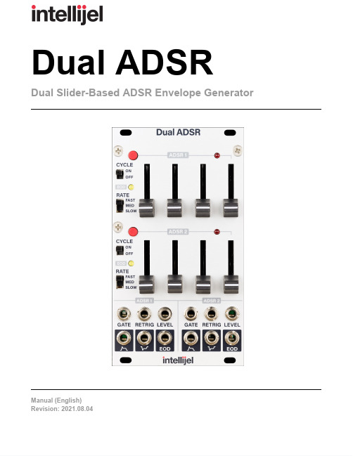
Dual A DSR Dual S lider-Based A DSR E nvelope G eneratorRevision: 2021.08.04TABLE O F C ONTENTSCOMPLIANCE 2 INSTALLATION 3 Installing Y our M odule 3 OVERVIEW 5 FRONT P ANEL 5 Controls 5 Inputs &O utputs 7 ENVELOPE T IMES 8 TECHNICAL S PECIFICATIONS 8COMPLIANCEThis d evice c omplies w ith P art 15 o f t he F CC R ules. O peration i s s ubject to t he f ollowing t wo c onditions: (1) t his d evice m ay n ot c ause h armful interference, a nd (2) t his d evice m ust a ccept a ny i nterference r eceived, including i nterference t hat m ay c ause u ndesired o peration.Changes o r m odifications n ot e xpressly a pproved b y I ntellijel D esigns, Inc. c ould v oid t he u ser’s a uthority t o o perate t he e quipment.Any d igital e quipment h as b een t ested a nd f ound t o c omply w ith t he limits f or a C lass A d igital d evice, p ursuant t o p art 15 o f t he F CC R ules. These l imits a re d esigned t o p rovide r easonable p rotection a gainst harmful i nterference w hen t he e quipment i s o perated i n a c ommercial environment. T his e quipment g enerates, u ses, a nd c an r adiate r adio frequency e nergy a nd, i f n ot i nstalled a nd u sed i n a ccordance w ith t he instruction m anual, m ay c ause h armful i nterference t o r adio communications.This d evice m eets t he r equirements o f t he f ollowing s tandards a nd directives:EMC: 2014/30/EUEN55032:2015 ;E N55103-2:2009 (EN55024) ;E N61000-3-2 ;EN61000-3-3Low V oltage: 2014/35/EUEN 60065:2002+A1:2006+A11:2008+A2:2010+A12:2011RoHS2: 2011/65/EUWEEE: 2012/19/EUINSTALLATIONIntellijel E urorack m odules a re d esigned t o b e u sed w ith a E urorack-compatible c ase a nd p ower supply. W e r ecommend y ou u se I ntellijel c ases a nd p ower s upplies.Before i nstalling a n ew m odule i n y our c ase, y ou m ust e nsure y our p ower s upply h as a f ree p ower header a nd s ufficient a vailable c apacity t o p ower t he m odule:●Sum u p t he s pecified +12V c urrent d raw f or a ll m odules, i ncluding t he n ew o ne. D o t he s ame f orthe -12 V a nd +5V c urrent d raw. T he c urrent d raw w ill b e s pecified i n t he m anufacturer'stechnical s pecifications f or e ach m odule.●Compare e ach o f t he s ums t o s pecifications f or y our c ase’s p ower s upply.●Only p roceed w ith i nstallation i f n one o f t he v alues e xceeds t he p ower s upply’s s pecifications.Otherwise y ou m ust r emove m odules t o f ree u p c apacity o r u pgrade y our p ower s upply.You w ill a lso n eed t o e nsure y our c ase h as e nough f ree s pace (hp) t o f it t he n ew m odule. T oprevent s crews o r o ther d ebris f rom f alling i nto t he c ase a nd s horting a ny e lectrical c ontacts, d o n ot leave g aps b etween a djacent m odules, a nd c over a ll u nused a reas w ith b lank p anels. S imilarly, d o not u se o pen f rames o r a ny o ther e nclosure t hat e xposes t he b ackside o f a ny m odule o r t he p ower distribution b oard.You c an u se a t ool l ike M odularGrid t o a ssist i n y our p lanning. F ailure t o a dequately p ower y our modules m ay r esult i n d amage t o y our m odules o r p ower s upply. I f y ou a re u nsure, p lease c ontact us b efore p roceeding.Installing Y our M oduleWhen i nstalling o r r emoving a m odule f rom y our c asealways t urn o ff t he p ower t o t he c ase a nd d isconnectthe p ower c able. F ailure t o d o s o m ay r esult i nserious i njury o r e quipment d amage.Ensure t he 10-pin c onnector o n t he p ower c able i sconnected c orrectly t o t he m odule b efore p roceeding.The r ed s tripe o n t he c able m ust l ine u p w ith t he-12V p ins o n t he m odule’s p ower c onnector. T he p insare i ndicated w ith t he l abel -12V, a w hite s tripe n extto t he c onnector, t he w ords “red s tripe”, o r s omecombination o f t hose i ndicators.Most m odules w ill c ome w ith t he c able a lreadyconnected b ut i t i s g ood t o d ouble c heck t heorientation. B e a ware t hat s ome m odules m ay h aveheaders t hat s erve o ther p urposes s o e nsure t hecable i s c onnected t o t he r ight o ne.The o ther e nd o f t he c able, w ith a16-pin c onnector,connects t o t he p ower b us b oard o f y our E urorackcase. E nsure t he r ed s tripe o n t he c able l ines u p w iththe -12V p ins o n t he b us b oard. O n I ntellijel p owersupplies t he p ins a re l abelled w ith t he l abel “-12V”and a t hick w hite s tripe:If y ou a re u sing a nother m anufacturer’s p owersupply, c heck t heir d ocumentation f or i nstructions.Once c onnected, t he c abling b etween t he m odule a nd p ower s upply s hould r esemble t he p icture below:Before r econnecting p ower a ndturning o n y our m odular s ystem,double c heck t hat t he r ibboncable i s f ully s eated o n b othends a nd t hat a ll t he p ins a recorrectly a ligned. I f t he p ins a remisaligned i n a ny d irection o rthe r ibbon i s b ackwards y ou c ancause d amage t o y our m odule,power s upply, o r o ther m odules.After y ou h ave c onfirmed a ll t heconnections, y ou c an r econnectthe p ower c able a nd t urn o nyour m odular s ystem. Y ou should i mmediately c heck t hat a ll y our m odules h ave p owered o n a nd a re f unctioning c orrectly. I f you n otice a ny a nomalies, t urn y our s ystem o ff r ight a way a nd c heck y our c abling a gain f ormistakes.OVERVIEWThe D ual A DSR c ontains t wo A DSR (A t tack D e cay S u stain R e lease) e nvelope g enerators m odelled after t hose f ound o n m any c lassic s ynthesizers. T he e nvelope g ates a re n ormalled s o t hey c an b e triggered f rom t he s ame g ate s ource o r i ndependently. T he c ycle s witches a llow t he e nvelopes t o be u sed a s u nipolar L FOs.FRONT P ANELThe f ollowing d escribe o ne o f t he t wo e nvelopes. T he f unctionality i s i dentical f or b oth A DSR 1 a nd ADSR 2 w ith t he e xception o f t he G ATE input.Controls[1]GATE B UTTONThe g ate b utton i s n ormalled t othe G ATE i nput. P ressing a ndholding t he b utton w ill a ctivate t heenvelope i n t he s ame w ay a s a nincoming g ate s ignal f rom akeyboard o r s equencer. I tprovides a u seful w ay t o t est o utthe e nvelope s ettings o r t omanually t o t rigger t he e nvelopeduring p erformance.[2]CYCLE S WITCHWhen i n t he O N p osition t he e ndof t he d ecay p hase w ill s tart t heattack p hase a gain.[3]EOD I NDICATOR L EDThis L ED i s l it w hen t he d ecayphase o f t he e nvelope h ascompleted a nd r emains l it t ill t henext t ime t he a ttack p hase b egins.The E OD o utput g ate w ill a lso b ehigh a t t he s ame t ime.[4]RATE S WITCHThe r ate s witch s elects b etweenthree d ifferent r anges f or t heattack, d ecay, a nd r elease t imes.In F AST m ode t he m aximum t imefor e ach s tage i s a pproximately 1second. I t i s a pproximately 10seconds i n M ED m ode, a nd 1minute i t S LOW m ode.[5]A[TTACK]This s lider s ets t he d uration o f t heenvelope a ttack s tage. T his i s t hetime i t t akes f or t he e nvelope l evelto g o f rom z ero t o t he m aximumlevel. T he d uration i s n early z erowith t he s lider a t t he b ottom, a ndthe l ongest w hen t he s lider i s a tthe t op. T he l ength o f t he l ongestsetting i s s et w ith t he R ATEswitch.[6]D[ECAY]This s lider s ets t he d uration o f t heenvelope d ecay s tage. T his i s t hetime i t t akes f or t he e nvelope l evelto g o f rom t he m aximum t o t hesustain l evel. T he l ength o f t helongest s etting i s s et w ith t heRATE s witch.[7]S[USTAIN]This s lider s ets t he l evel o f t hesustain s tage. I t i s 0V a t t hebottom a nd 5V a t t he t op.[8]R[ELEASE]This s lider s ets t he d uration o f t he e nvelope r elease s tage. T his i s t he t ime i t t akes t he e nvelope to g o f rom t he s ustain l evel b ack t o 0a fter t he g ate i s r eleased. T he l ength o f t he l ongest s etting is s et w ith t he R ATE s witch.[9]LEVEL I NDICATORThe b rightness o f t his L ED i ndicates t he l evel o f t he e nvelope.Inputs &O utputs[A]GATEWhile t he g ate i nput i s h igh t heenvelope m oves t hrough i tsstages u ntil i t h its t he s ustainstage. I f a t a ny t ime t he g ate g oeslow t he e nvelope w ill e nter t herelease s tage.For A DSR 2t his i nput i snormalled t o t he i nput o f A DSR 1so t hat w hen n o c able i sconnected t he G ATE o f A DSR 2,a g ate s ignal a t A DSR 1c antrigger b oth e nvelopes.[B]RETRIGWhen a t rigger i s r eceived a t t hisinput w hile t he g ate i s h igh i tresets t he e nvelope b ack t o 0a ndstarts t he a ttack p hase a gain.[C]LEVELThis i nput e xpects a0t o 5Vsignal a nd c ontrols t he o veralllevel o f t he e nvelope v ia a b uilt-inlinear V CA. I t i s n ormalled t o a5V s ource s o w hen n othing i sconnected t he e nvelope u ses i tsmaximum r ange.[D]OUTPUTThis i s t he p rimary e nvelope o utput. T he l evel i s f rom 0t o 5V.[E]INVERTED O UTPUTThis o utput p rovides t he i nverted v ersion o f t he e nvelope, f rom 0t o -5 V.[F]EODThis g ate o utput g oes h igh o nce t he e nvelope c ompletes t he d ecay p hase a nd r emains h igh until t he n ext a ttack p hase.ENVELOPE T IMESNOTE: T imes a re a pproximate a nd w ill v ary f rom u nit t o u nit d ue t o c omponent t olerances.TECHNICAL S PECIFICATIONSMODEMINIMUMATTACK T IMEMAXIMUMATTACK T IMEMINIMUMDECAY/RELEASETIMEMAXIMUMDECAY/RELEASETIMEFast 0.2 m s 1.5 s 0.6 m s 2.5 s Medium 1.8 m s 10 s 3.5 m s 10 s Slow 9.3 m s60 s30 m s60 sWidth14 h p Maximum D epth 38 m mCurrent D raw 60 m A @ +12V49 m A @ -12V。
触摸芯片TS08N技术条件
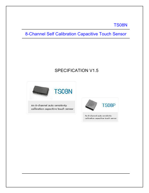
TS08N(8-CH Auto Sensitivity Calibration Capacitive Touch Sensor) 1Specification1.1General Feature32QFN24SOPDrawings not to scaleTS08N(8-CH Auto Sensitivity Calibration Capacitive Touch Sensor) 2Pin Description2.124SOP packageTS08N (8-CH Auto Sensitivity Calibration Capacitive Touch Sensor)2.2 32QFN packagePIN No. Name I/O DescriptionProtection 1 RBIAS Analog Input Internal bias adjust inputVDD/GND 2 VSS Analog Input -VDD/GND 3 CS5 Analog Input CH5 capacitive sensor input VDD/GND 4 CS6 Analog Input CH6 capacitive sensor input VDD/GND 5 CS7 Analog Input CH7 capacitive sensor input VDD/GND 6 CS8 Analog Input CH8 capacitive sensor input VDD/GND 7 CDEG Analog Input3 step sensitivity level selection VDD/GND8 N.C. - No Connection - 9 N.C. - No Connection - 10 N.C. - No Connection - 11 N.C. - No Connection - 12 N.C. - No Connection - 13 VSS Ground Supply ground VDD 14 DUMMY - No Connection Note 1 - 15 N.C. - No Connection- 16 RST Digital Input System reset (High reset) VDD/GND 17 OUT1 Digital Output CH1 output (Open drain) VDD/GND 18 OUT2 Digital Output CH2 output (Open drain) VDD/GND 19 OUT3 Digital Output CH3 output (Open drain) VDD/GND 20 OUT4 Digital Output CH4 output (Open drain) VDD/GND 21 N.C. -No Connection- 22 OUT5 Digital Output CH5 output (Open drain) VDD/GND 23 OUT6 Digital Output CH6 output (Open drain) VDD/GND 24 OUT7 Digital Output CH7 output (Open drain) VDD/GND 25 OUT8 Digital Output CH8 output (Open drain) VDD/GND 26 IMP_SEL Digital Input Sense line impedance selection VDD/GND 27 SYNC/OPTDigital Input/Output Output mode selection(Single Output / Multi Output Note 2) Sync pulse input /output VDD/GND 28 VDD Power Power (2.5V~5.0V)GND 29 CS1 Analog Input CH1 capacitive sensor input VDD/GND 30 CS2 Analog Input CH2 capacitive sensor input VDD/GND 31CS3Analog InputCH3 capacitive sensor inputVDD/GND 32 CS4 Analog Input CH4 capacitive sensor input VDD/GNDNote 1 : DUMMY pin should be no connection. Note 2 : Refer to 6.4 SYNC/OPT implementationTS08N (8-CH Auto Sensitivity Calibration Capacitive Touch Sensor)3 Absolute Maximum RatingBattery supply voltage 5.5VMaximum voltage on any pin VDD+0.3 Maximum current on any PAD 100mA Power Dissipation 800mW Storage Temperature -50 ~ 150℃ Operating Temperature -20 ~ 75℃ Junction Temperature 150℃Note Unless any other command is noted, all above are operated in normal temperature.4 ESD & Latch-up Characteristics4.1 ESD CharacteristicsModePolarityMax Reference 2000VVDD 2000V VSS H.B.MPos / Neg2000V P to P 200VVDD 200V VSS M.MPos / Neg200V P to P500VC.D.MPos / Neg800VDIRECT 4.2 Latch-up CharacteristicsModePolarity Max Test StepPositive200mAI TestNegative-200mA 25mA V supply over 5.0VPositive8.0V1.0VTS08N (8-CH Auto Sensitivity Calibration Capacitive Touch Sensor)5 Electrical Characteristics (Preliminary)▪ V DD =3.3V, Rb=510k, (Unless otherwise noted), T A = 25℃Characteristics Symbol Test Condition Min Typ Max Units Operating supply voltage V DD2.53.3 5.0 V V DD = 3.3V R B =510k - 80 130Current consumption I DD V DD = 5.0V R B =510k- 200 315㎂ Output maximum sinkcurrent I OUT T A = 25℃- - 4.0 ㎃ Sense input capacitance rangeNote1 C S - 10 100㎊ Sense input resistance range R S- 200 1000ΩCs = 10pF, C DEG = 200pF 0.2 - - Cs = 10pF, C DEG = 470pF 0.4 - - Minimum detective capacitance differenceΔCCs = 10pF, C DEG = 1000pF 0.8 - - ㎊ΔC > 0.2pF, Cs = 10pF, C DEG = 200pF- 12 -Output impedance (open drain) ZoΔC < 0.2pF, Cs = 10pF, C DEG = 200pF - 30M - ΩV DD = 3.3V R B = 510k - 100 - Self calibration time aftersystem reset T CALV DD = 5.0V R B = 510k - 80 - msV DD = 2.5V 100 200 470V DD = 3.3V 200 330 680Recommended bias resistance rangeNote2R BV DD = 5.0V 300 510 1000kΩ Maximum bias capacitance C B_MAX - 820 1000pF Recommended sync resistance rangeR SYNC12 20MΩ High sensitivity Note 4Short Medium sensitivityOpenLow sensitivity @V DD =3.3V, 5.0V - 430 - Sensitivity level selectionC DEGNote 3Low sensitivity @V DD =2.5V-470-㎊Note 1: The sensitivity can be increased with lower C S value .The recommended value of C S is 10pF when using 3T PC(Poly Carbonate) cover and 10㎜ x 7㎜ touch pattern. Note 2: The lower R B is recommended in noisy condition. Note 3: C DEG should be in ± 5% tolerance.Note 4: High sensitivity is not recommended in noisy application.TS08N(8-CH Auto Sensitivity Calibration Capacitive Touch Sensor) 6TS08N Implementation6.1R_BIAS implementationR BTS08N(8-CH Auto Sensitivity Calibration Capacitive Touch Sensor) 6.2CS implementationR S8R S1TS08N(8-CH Auto Sensitivity Calibration Capacitive Touch Sensor)Sensitivity example figure at High sensitivityCDEG implementationGND: Higher SensitivityTS08N(8-CH Auto Sensitivity Calibration Capacitive Touch Sensor) 6.4SYNC/OPT implementation6.4.1 Single ConnectionR SYNCTS08N(8-CH Auto Sensitivity Calibration Capacitive Touch Sensor)6.5RESET implementationTS08N has internal data latches, so initial state of these latches must be reset by external reset pulse before normal operation starts. The reset pulse can be controlled by host MCU directly orCTS08N(8-CH Auto Sensitivity Calibration Capacitive Touch Sensor) 6.6Output Circuit ImplementationRRRRROUT6OUT7OUT8TS08N(8-CH Auto Sensitivity Calibration Capacitive Touch Sensor) 6.7IMP_SEL (Sense Line Impedance) ImplementationTS08N(8-CH Auto Sensitivity Calibration Capacitive Touch Sensor) 7Recommended Circuit DiagramTheTS08N(8-CH Auto Sensitivity Calibration Capacitive Touch Sensor) 7.1Example – Power Line Split Strategy PCB LayoutThe noise that is generated by AC load or relay can be loaded at 5V power line. B. Split power Line (One 5V regulator used) – RecommendedC. Split power Line (Separated 5V regulator used) – Strongly recommendedTS08N(8-CH Auto Sensitivity Calibration Capacitive Touch Sensor) 8MECHANICAL DRAWING8.1Mechanical Drawing (24 SOP)TS08N(8-CH Auto Sensitivity Calibration Capacitive Touch Sensor) 8.2Mechanical Drawing (32 QFN)TS08N(8-CH Auto Sensitivity Calibration Capacitive Touch Sensor)TS08N(8-CH Auto Sensitivity Calibration Capacitive Touch Sensor) 9MARKING DESCRIPTIONDevice Code : T S 0 8 N www.epsillon.cz。
BTM02E-08蓝牙模块
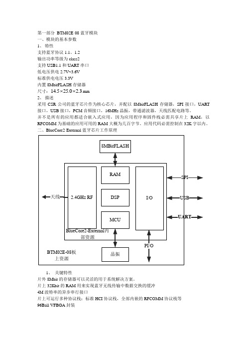
第一部分BTM02E-08蓝牙模块一、模块的基本参数1、特性支持蓝牙协议1.1、1.2输出功率等级为class2支持USB1.1和UART串口低电压供电2.7V~3.6V标准供电电压3.3V内置8MbitFLASH存储器尺寸:14.525.0 2.3⨯⨯mm2、描述采用CSR公司的蓝牙芯片作为核心芯片,并配以8MbitFLASH存储器,SPI接口,UART 接口,USB接口,PCM音频接口,16MHz晶振,带通滤波器,天线匹配电路等。
并不是所有的应用都适合嵌入式应用,因为应用程序和固件栈必需共享片上RAM,以RFCOMM为基础的应用可用的RAM大概为几百字节。
应用代码必需控制在32K字以内。
二、BlueCore2-External蓝牙芯片工作原理1、关键特性片外8Mbit的存储器可以灵活的用于系统解决方案。
片上32Kbit的RAM用来实现蓝牙无线传输中数据交换的缓冲4M波特率的异步串行接口片上可运行多种协议栈:标准HCI协议栈,全部内嵌的RFCOMM协议栈等96Ball-VFBGA封装2、管脚使用USB接口不用时应接地所有IO管脚被配置成输入时,复位后将变成弱下拉不用的AIO(可编程模拟IO)管脚不使用时应该悬空3、内部功能模块USB:用来与其他数字设备的通用接口,BlueCore02扮演外围设备角色,来回应主机的请求SPI(异步串行接口):用来与其它数字设备的接口,SPI口可以用来调试软件和烧写外部FLASH存储器UART:与其他设备通信的通用同步串口可编程IO:共有15个可编程管脚(12个数字的和3个模拟的),有运行在片上的固件来控制4、CSR 软件栈CSR为BlueCore2提供了片上运行的固件(Firmware),片上运行的协议栈仍需HCI的支持1)HCI Stack该Firmware提供了一组特性及支持相应特性的HCI在标准蓝牙协议上做了扩展:●支持蓝牙串口协议——BCSP,一种以UART为物理层,可靠的特有协议(可选)●提供了额外的50个系列HCI指令●可以访问可编程IO端口●访问蓝牙时钟●访问固件上的随机数产生器●动态配置UART(波特率,校验,数据位)●无线传输使能:一个简单的命令,与一个专门的物理开关有关,确定radio是否可以传输数据●可以读取芯片外部管脚上的电压,可以运行在VM或主机上来电池的监测●提供一组BCCMD命令,来访问片上的“persist store”,该数据库存储了器件的蓝牙地址,器件class,radio配置,USB/DFU常数等(Device Firmware Upgrade)●UART上break命令的应用:用于重启,开机进入低功耗,唤醒主机●提供一组“radio test”或者BIST 指令,直接控制片上的radio●虚拟机。
Professional元件库列表及中英文对照合并版
交流电源ALTERNATOR模拟芯片(AnalogICs)放大器(Amplifiers)比较器(Comparators)显示驱动器(DisplayDrivers)过滤器(Filters)数据选择器(Multiplexers)稳压器(Regulators)定时器(Timers)基准电压(VoltageReference)杂类(Miscellananeous)电容(Capacitors)可动态显示充放电电容(Animated)音响专用轴线电容(AudioGrade Axial)轴线聚苯烯电容(AxialLead Polypropene)轴线聚苯烯电容(AxialLead Polystyrene)陶瓷圆片电容(CeramicDisc)去耦片状电容(DecouplingDisc)普通电容(Generic)高温径线电容(HighTemp Radial)高温径线电解电容(HighTemperature Axial Electrolytic)金属化聚酯膜电容(MetallisedPolyester Film)金属化聚烯电容(MetallisedPolypropene)金属化聚烯膜电容(MetallisedPolypropene Film)小型电解电容(MinitureElectrolytic)多层金属化聚酯膜电容(Multilayer MetallisedPolyestern Film) 聚脂膜电容(Mylar Film)镍栅电容(Nickel Barrier)无极性电容(Non Polarised)聚脂层电容(Polyester Layer)径线电解电容(Radial Electrolytic)树脂蚀刻电容(Resin Dipped)钽珠电容(Tantalum Bead)可变电容(Variable)VX轴线电解电容(VXAxial Electolytic) 连接器(Connectors)音频接口(Audio)D 型接口(D-Type)双排插座(DIL)插头(Header Blocks)PCB转接器(PCBTransfer)带线(Ribbon Cable)单排插座(SIL)连线端子(Terminal Blocks)杂类(Miscellananeous)数据转换器(Data Converter)模/数转换器(A/D converters)数/模转换器(D/A converters)采样保持器(Sample & Hold)温度传感器(Temperature Sensore)调试工具(Debugging Tools)断点触发器(Breakpoint Triggers)逻辑探针(Logic Probes)逻辑激励源(Logic Stimuli)二极管(Diode)整流桥(Bridge Rectifiers)普通二极管(Generic)整流管(Rectifiers)肖特基二极管(Schottky)开关管(Switching)隧道二极管(Tunnel)变容二极管(Varicap)齐纳击穿二极管(Zener)ECL 10000系列(ECL 10000 Series) 各种常用集成电路机电(Electromechanical)各种直流和步进电机电感(Inductors)普通电感(Generic)贴片式电感(SMT Inductors)变压器(Transformers)拉普拉斯变换(Laplace Primitives)一阶模型(1st Order)二阶模型(2st Order)控制器(Controllers)非线性模式(Non-Linear)算子(Operators)极点/零点(Poles/Zones)符号(Symbols)存储芯片(Memory Ics)动态数据存储器(Dynamic RAM)电可擦除可编程存储器(EEPROM)可擦除可编程存储器(EPROM)I2C总线存储器(I2C Memories)SPI总线存储器(SPIMemories)存储卡(Memory Cards)静态数据存储器(Static Memories)微处理器芯片(Microprocess ICs) 6800 系列(6800Family)8051 系列(8051Family)ARM 系列(ARM Family)AVR 系列(AVR Family)Parallax 公司微处理器(BASIC Stamp Modules)HCF11 系列(HCF11Family)PIC10 系列(PIC10Family)PIC12 系列(PIC12Family)PIC16 系列(PIC16Family)PIC18 系列(PIC18Family)Z80系列(Z80 Family)CPU 外设(Peripherals)杂项(Miscellaneous)含天线、ATA/IDE硬盘驱动模型、单节与多节电池、串行物理接口模型、晶振、动态与通用保险、模拟电压与电流符号、交通信号灯建模源(Modelling Primitives)模拟(仿真分析)(Analogy-SPICE)数字(缓冲器与门电路)(Digital--Buffers&Gates)数字(杂类)(Digital--Miscellaneous)数字(组合电路)(Digital--Combinational)数字(时序电路)(Digital--Sequential)混合模式(Mixed Mode)可编程逻辑器件单元(PLD Elements)实时激励源(Realtime Actuators)实时指示器(Realtime Indictors)运算放大器(Operational Amplifiers)单路运放(Single)二路运放(Dual)三路运放(Triple)四路运放(Quad)八路运放(Octal)理想运放(Ideal)大量使用的运放(Macromodel)光电子类器件(Optoelectronics)七段数码管(7-Segment Displays)英文字符与数字符号液晶显示器(Alphanumeric LCDs) 条形显示器(Bargraph Displays)点阵显示屏(Dot Matrix Display)图形液晶(Grphical LCDs)灯泡(Lamp)液晶控制器(LCD Controllers)液晶面板显示(LCD Panels Displays)发光二极管(LEDs)光耦元件(Optocouplers)串行液晶(Serial LCDs)可编程逻辑电路与现场可编程门阵列(PLD&FPGA)无子类电阻(Resistors)0.6W金属膜电阻(0.6WMetal Film)10W 绕线电阻(10WWirewound)2W 金属膜电阻(2W MetalFilm)3W 金属膜电阻(3W MetalFilm)7W 金属膜电阻(7W MetalFilm)通用电阻符号(Generic)高压电阻(High Voltage)负温度系数热敏电阻(NTC)排阻(Resisters Packs)滑动变阻器(Variable)可变电阻(Varistors)仿真源(Simulator Primitives)触发器(Flip-Flop)门电路(Gates)电源(Sources)扬声器与音响设备(Speaker&Sounders)无子分类开关与继电器(Switch&Relays)键盘(Keypads)普通继电器(Generic Relays)专用继电器(Specific Relays)按键与拨码(Switchs)开关器件(Switching Devices)双端交流开关元件(DIACs)普通开关元件(Generic)可控硅(SCRs)三端可控硅(TRIACs)热阴极电子管(Thermionic Valves)二极真空管(Diodes)三极真空管(Triodes)四极真空管(Tetrodes)五极真空管(Pentodes)转换器(Transducers)压力传感器(Pressures)温度传感器(Temperature)晶体管(Transistors)双极性晶体管(Bipolar)普通晶体管(Generic)绝缘栅场效应管(IGBY/Insulated Gate BipolarTransistors 结型场效应晶体管(JFET)金属-氧化物半导体场效应晶体管(MOSFET)射频功率LDMOS晶体管(RF Power LDMOS)射频功率VDMOS晶体管(RF Power VDMOS)单结晶体管(Unijunction)CMOS 4000系列(CMOS 4000 seriesTTL 74系列(TTL 74series)TTL 74增强型低功耗肖特基系列(TTL74ALS Series)TTL 74增强型肖特基系列(TTL74AS Series)TTL 74高速系列(TTL 74FSeries)TTL 74HC系列/CMOS工作电平(TTL 74HCSeries)TTL 74HCT系列/TTL工作电平(TTL 74HCTSeries)TTL 74低功耗肖特基系列(TTL74LS Series)TTL 74肖特基系列(TTL 74SSeries)加法器(Adders)缓冲器/驱动器(Buffers&Drivers)比较器(Comparators)计数器(Counters)解码器(Decoders)编码器(Encoders)存储器(Memory)触发器/锁存器(Flip-Flop&Latches)分频器/定时器(Frequency Dividers & Timers)门电路/反相器(Gates&Inverters)数据选择器(Multiplexers)多谐振荡器(Multivibrators)振荡器(Oscillators)锁相环(Phrase-Locked-Loop,PLL)寄存器(Registers)信号开关(Signal Switches)收发器(Tranxceivers)杂类逻辑芯片(Misc.Logic)Proteusisis的元件库中英对照Proteus 元件名称对照1元件名称中文名说明7407 驱动门1N914 二极管74Ls00 与非门74LS04 非门74LS08 与门74LS390 TTL 双十进制计数器7SEG 4针BCD-LED 输出从0-9 对应于4根线的BCD码7SEG 3-8译码器电路BCD-7SEG[size=+0]转换电路ALTERNATOR 交流发电机AMMETER-MILLI mA安培计AND 与门BATTERY 电池/电池组BUS 总线CAP 电容CAPACITOR 电容器CLOCK 时钟信号源CRYSTAL 晶振D-FLIPFLOP D触发器FUSE 保险丝GROUND 地LAMP 灯LED-RED 红色发光二极管LM016L 2行16列液晶可显示2行16列英文字符,有8位数据总线D0-D7,RS,R/W,EN三个控制端口(共14线),工作电压为5V。
VS8传感器系列产品说明书
VS8 Sensor Series Instruction ManualOriginal Instructions201958 Rev. B31 May 2018© Banner Engineering Corp. All rights reservedContents1 Product Description (3)1.1 Models (3)1.2 Features (4)2 Sensor Installation (5)2.1 Wiring Diagrams (5)3 Sensor Configuration (6)3.1 Remote Configuration – 4-Pin Models (6)3.2 Two-Point Static Background Suppression (6)3.3 One-Point Static Background Suppression (7)3.4 Dynamic Background Suppression (8)3.5 Two-Point Static Opposed and Retroreflective (9)3.6 Dynamic Opposed and Retroreflective (10)3.7 Select Light Operate/Dark Operate – 4-Pin Models (11)4 Specifications (12)4.1 Dimensions (12)5 Performance Curves (13)5.1 Beam Spot Sizes (13)6 Accessories (14)6.1 Cordsets for VS8 Models with Suffix Q (14)6.2 Cordsets for VS8 Models with Suffix Q3 (14)6.3 Cordsets for VS8 Models with Suffix Q5 (14)6.4 Brackets (15)6.5 Retroreflectors (16)7 Banner Engineering Corp. Limited Warranty (17)1 Product Description•Miniature sensor for installation in the smallest of spaces•Red laser models provide bright, precise laser light spot for optimum small part detection •High switching frequency for detection in even the fastest processes•User-friendly operation using electronic push button or remote input provides reliable and precise detection•Red laser, Red LED, and Blue LED types available to match sensing beam to application •Robust, glass-fiber-reinforced plastic housing •PNP or NPN output, depending on modelWARNING: Not To Be Used for Personnel ProtectionNever use this device as a sensing device for personnel protection. Doing so could lead to serious injury or death. This device does not include the self-checking redundant circuitry necessary to allow its use in personnel safety applications. A sensor failure or malfunction can cause either an energized or de-energized sensor output condition.1.1 Models1.2 Features1234Figure 1. VS8 Sensor FeaturesFeatures1.Green Indicator2.Amber Indicator3.TEACH Button - Laser Adjustable Field (LAF),Adjustable Field (AF), Polar Retro (LP), and Receiver (R)Models4.Optical Windowsuffix "Q" to the model number. For example, VS8EAPAF70Q. Only available for AF and LAF models.•To order the 200 mm (7.8 in) PUR cable model with a 3-pin M8/Pico-style quick disconnect, add suffix "Q3" to the model number. For example, VS8APFF15Q3. Only available for FF models.•To order the 200 mm (7.8 in) PUR cable model with a 4-pin M12/Euro-style quick disconnect, add suffix "Q5" to the model number. For example, VS8EAPAF70Q5. Only available for AF and LAF models.2 Sensor InstallationInstall the sensor so the object to be detectedmoves horizontally to the sensor.Figure 2. VS8 Sensor Installation2.1 Wiring Diagrams3-Pin NPN Models3-Pin PNP Models–+Key1.Brown2.White3.Blue4.Black4-Pin NPN Models–+ 4-Pin PNP ModelsOpposed Mode EmittersNote: All 4-pin and cabled models have a remote input on the white wire (pin-2).3 Sensor Configuration•Expert™ 4-pin background suppression, retroreflective, and opposed mode receiver models are configurable using either the sealed push button or the remote input wire.•3-pin fixed field and opposed mode emitter models require no user adjustments.•The remote input wire (pin-2/white wire) is used to select light or dark operate or perform the desired TEACH method. Pulse durations for the remote input wire correspond to the indicated press durations of the push button.3.1 Remote Configuration – 4-Pin ModelsThe remote input wire (pin-2/white wire) is used to select light or dark operate, or perform the desired TEACH method. Closing and opening times for the remote input wire correspond to the indicated press/hold durations of the push button.3.2 Two-Point Static Background SuppressionTwo-point TEACH sets a single switch point. The sensor sets the switch point between two taught target distances, relative to the shifted origin location.1.Present the target.2.Start TEACH mode.3.Present the background or second target.4.Configure the sensor.3.3 One-Point Static Background SuppressionOne-point TEACH sets a single switch point. The sensor sets the switch point just behind the taught target distance.1.Present the target.2.Start TEACH mode.3.Configure the sensor.3.4 Dynamic Background SuppressionDynamic TEACH sets a single switch point during machine run conditions. Dynamic TEACH is recommended for applications where a machine or process may not be stopped for teaching. The sensor takes multiple samples and the switch point is set just behind the farthest taught target distance, accounting for a static background.1.Present the target.2.Start TEACH mode.3.Configure the sensor.3.5 Two-Point Static Opposed and RetroreflectiveTwo-point TEACH for Opposed and Retroreflective modes sets a single switching level. The sensor sets the switching level between the blocked and unblocked conditions.1.Align the sensor.2.Start TEACH mode.3.Present the target.4.Configure the sensor.3.6 Dynamic Opposed and RetroreflectiveDynamic TEACH for Opposed and Retroreflective modes sets a single switching level during machine run conditions. Dynamic TEACH is recommended for applications where a machine or process may not be stopped for teaching. The sensor takes multiple samples and the switching level is set between the blocked and unblocked conditions.1.Present the target.2.Start TEACH mode.3.Configure the sensor.3.7 Select Light Operate/Dark Operate – 4-Pin ModelsChange the sensor operation to light operate or dark operate for the desired application. Use either the button or the remote input wire procedure to configure the sensor.4 SpecificationsSupply Voltage and CurrentLED models: 10 V dc to 30 V dc (10% max. ripple) at less than 20 mA,exclusive of loadLaser models: 10 V dc to 30 V dc (10% max. ripple) at less than 12 mA,exclusive of load Supply Protection CircuitryProtected against reverse polarity and short-circuitOutput Protection CircuitryProtected against output short-circuit, continuous overload, and false pulse on power-up Output ConfigurationRetroreflective and Background Suppression Models: Single PNP or NPN on pin 4 (black wire) with remote input on pin 2 (white wire)Opposed Mode Receivers only: Single PNP or NPN on pin 4 (black wire)with remote input on pin 2 (white wire)Output Response Time 500 µs Output Rating 50 mA Indicators2 LED indicators on sensor top Green on: Power onAmber on: Output conducting Emitter LED Wavelength Red LED models: 650 nm Blue LED models: 450 nm Laser models: 655 nmEffective Beam 5.5 mmThis can be adjusted without an aperture by teaching the sensor Connections2 m (6.5 ft) unterminated 4-wire PUR cable or 200 mm (7.8 in) PUR cable with a 3- or 4-pin M8/Pico-style or 4-pin M12/Euro-style male quick disconnect, depending on modelModels ending in suffix "Q", "Q3", or "Q5" must be used with a UL recognized cordset R/C (CYJV2)Search p/n 201958 at to view the Instruction Manual for more information on cordsets Switching Frequency ≤ 1000 Hz Delay Before Power-Up < 300 msLaser ClassificationsAll Models: Class 1; wavelength: 655 nm; frequency: 5 kHz; pulse duration: 3.2 µs; limit value pulse: ≤ 2.3 mW. Reference IEC 60825-1:2001, Section 8.2.All Models: Complies with 21 CFR 1040.10 and 1040.11 except for deviations pursuant to laser Notice No. 50 dated June 24, 2007.Blue LED Models: Risk Group 2; possibly hazardous optical radiation emitted from this product. Do not stare at the operating lamp. May be harmful to the eyes. (EN62471)Opposed Mode Model Adjustments Push button teach input (Receivers)Remote wire teach input (Receivers)Remote wire beam inhibit (Emitters)ConstructionHousing, cable: PUR Front screen: PMMAOperating ConditionsLED models: –20 °C to +60 °C (–4 °F to +140 °F)Laser models: –20 °C to +50 °C (–4 °F to +122 °F)Storage Temperature: –20 °C to +80 °C (–4 °F to +176 °F)UL Operating Temperature: –20 °C to +30 °C (–4 °F to +86 °F)Chemical CompatibilityECOLAB ® certified (2 m cabled models only)Environmental Rating IEC IP67Certifications4.1 DimensionsAll measurements are listed in millimeters [inches], unless noted otherwise.Sensor with Bracket (SMBVS8DT)5 Performance Curves5.1 Beam Spot SizesOpposed ModeDistance (m)S i z e (m m )05101520253012345RetroreflectiveDistance (m)S i z e (m m )00204060801001201400.20.40.60.81 1.4 1.61.2Laser RetroreflectiveDistance (m)S i z e (m m )0246810121416Fixed Field Background Suppression with Blue LEDDistance (mm)S i z e(m m )01234561020304050Fixed Field Background SuppressionDistance (mm)S i z e(m m )01234561020304050Adjustable Field Background SuppressionDistance (mm)S i z e (m m )1234566 Accessories6.1 Cordsets for VS8 Models with Suffix QAll measurements are listed in millimeters, unless noted otherwise.6.2 Cordsets for VS8 Models with Suffix Q36.3 Cordsets for VS8 Models with Suffix Q5All measurements are listed in millimeters, unless noted otherwise.4-Pin Threaded M12/Euro-Style CordsetsCable: PVC jacket, PUR (polyurethane) connector body, nickel-plated brass coupling nut Conductors: 22 AWG, gold-plated contactsConductors: 22 AWG, gold-plated contactsVoltage/Current Rating: 250 V ac/dc, 4.0 ATemperature: –40 °C to +105 °C (–40 °F to +221 °F)Environmental Rating: IP67/IP69K6.4 Brackets6.5 RetroreflectorsNote: For maximum adhesion of all tape products, surfaces must be clean.These are sealed micro-prism style pieces and may not be cut.7 Banner Engineering Corp. Limited WarrantyBanner Engineering Corp. warrants its products to be free from defects in material and workmanship for one year following the date of shipment. Banner Engineering Corp. will repair or replace, free of charge, any product of its manufacture which, at the time it is returned to the factory, is found to have been defective during the warranty period. This warranty does not cover damage or liability for misuse, abuse, or the improper application or installation of the Banner product.THIS LIMITED WARRANTY IS EXCLUSIVE AND IN LIEU OF ALL OTHER WARRANTIES WHETHER EXPRESS OR IMPLIED (INCLUDING, WITHOUT LIMITATION, ANY WARRANTY OF MERCHANTABILITY OR FITNESS FOR A PARTICULAR PURPOSE), AND WHETHER ARISING UNDER COURSE OF PERFORMANCE, COURSE OF DEALING OR TRADE USAGE.This Warranty is exclusive and limited to repair or, at the discretion of Banner Engineering Corp., replacement. IN NO EVENT SHALL BANNER ENGINEERING CORP. BE LIABLE TO BUYER OR ANY OTHER PERSON OR ENTITY FOR ANY EXTRA COSTS, EXPENSES, LOSSES, LOSS OF PROFITS, OR ANY INCIDENTAL, CONSEQUENTIAL OR SPECIAL DAMAGES RESULTING FROM ANY PRODUCT DEFECT OR FROM THE USE OR INABILITY TO USE THE PRODUCT, WHETHER ARISING IN CONTRACT OR WARRANTY, STATUTE, TORT, STRICT LIABILITY, NEGLIGENCE, OR OTHERWISE.Banner Engineering Corp. reserves the right to change, modify or improve the design of the product without assuming any obligations or liabilities relating to any product previously manufactured by Banner Engineering Corp. Any misuse, abuse, or improper application or installation of this product or use of the product for personal protection applications when the product is identified as not intended for such purposes will void the product warranty. Any modifications to this product without prior express approval by Banner Engineering Corp will void the product warranties. All specifications published in this document are subject to change; Banner reserves the right to modify product specifications or update documentation at any time. Specifications and product information in English supersede that which is provided in any other language. For the most recent version of any documentation, refer to: .。
- 1、下载文档前请自行甄别文档内容的完整性,平台不提供额外的编辑、内容补充、找答案等附加服务。
- 2、"仅部分预览"的文档,不可在线预览部分如存在完整性等问题,可反馈申请退款(可完整预览的文档不适用该条件!)。
- 3、如文档侵犯您的权益,请联系客服反馈,我们会尽快为您处理(人工客服工作时间:9:00-18:30)。
•
• • • •
Costs: average cost per customer
Profits: rising Marketing Objective: maximize market share Product: offer extension, service, warranty Price: penetration strategy
•
•
Price: use cost-plus formula
Distribution: build selective distribution
•
Promotion: heavy to entice product trial
8 - 18
Growth Stage of PLC
• Sales: rapidly rising
8-8
Marketing Strategy Development
•
Part One Describes:
The target market, planned product positions, sales, market share, and profit goals
•
Part Two Outlines the First Year’s:
8 - 11
Test Marketing
• Product and program introduced in more realistic market setting.
•
•
Not needed for all products.
Can be expensive and time consuming, but better than making major marketing mistake.
•
Commercialization
8-5
Idea Generation
• • • • • Company employees Customers Competitors Distributors Suppliers
8-6
Idea Screening
• • Process to spot good ideas and drop poor ones. Develop system to estimate: market size, product price, development time and costs, manufacturing costs, and rate of return. Evaluate these findings against set of company criteria for new products.
8 -ems of PLC
• • Hard to identify which stage of the PLC the product is in. Hard to pinpoint when the product moves to the next stage.
•
•
Distribution: build intensive distribution
Promotion: reduce to take advantage of demand
8 - 19
Maturity Stage of PLC
• • • • • • • • Sales: peak Costs: low cost per customer Profits: high Marketing Objective: maximize profits while defending market share Product: diversify brand and models Price: match or best competitors Distribution: build more intensive distribution Promotion: Increase to encourage brand switching
•
• •
Hard to identify factors that affect product’s movement through stages.
Hard to forecast sales level, length of each stage, and shape of PLC. Strategy is both a cause and result of the PLC.
• Involves a review of the sales, costs, and profit projections to assess fit with company objectives.
•
If yes, move to the product development phase.
8 - 10
8-7
•
Concept Development and Testing
•
• •
Product Idea: idea for a possible product that the company can see itself offering. Product Concept: detailed version of the idea stated in meaningful consumer terms. Product Image: the way consumers perceive an actual or potential product.
8 - 12
Commercialization
•
•
•
Must decide on timing (i.e., when to introduce the product). Must decide on where to introduce the product (e.g., single location, state, region, nationally, internationally). Must develop a market rollout plan.
Product’s planned price, distribution, and marketing budget
•
Part Three Describes Long-Run:
Sales and profit goals, marketing mix strategy
8-9
Business Analysis
8 - 14
•
The Product Life Cycle
• • • • • Product development Introduction Growth Maturity Decline
8 - 15
Product Life Cycle Applications
• • • • • Product class has the longest life cycle (e.g., gaspowered cars) Product form tends to have the standard PLC shape (e.g., dial telephone) Brand can change quickly because of changing competitive attacks and responses (e.g., Tide, Cheer) Style is a basic and distinctive mode of expression (e.g., formal clothing, Danish modern furniture) Fashion is a popular style in a given field (e.g., business casual) Fad is a fashion that enters quickly, is adopted quickly, and declines fast (e.g., pet rocks)
8 - 17
Introduction Stage of PLC
• • • • • Sales: low Costs: high cost per customer Profits: negative Marketing Objective: create product awareness and trial Product: offer a basic product
Overestimation of market size Design problems Incorrectly positioned, priced, or advertised Pushed despite poor marketing research findings Development costs Competition
Product Development
•
• • •
Develop concept into physical product Calls for large jump in investment Prototypes are made Prototype must have correct physical features and convey psychological characteristics
8-4
Major Stages in NewProduct Development
• • Idea generation Idea screening
•
• • • •
Concept development and testing
Marketing strategy development Business analysis Product development Test marketing
