JQX-115F-TH中文资料
JQX-14FC22AZ5中文资料
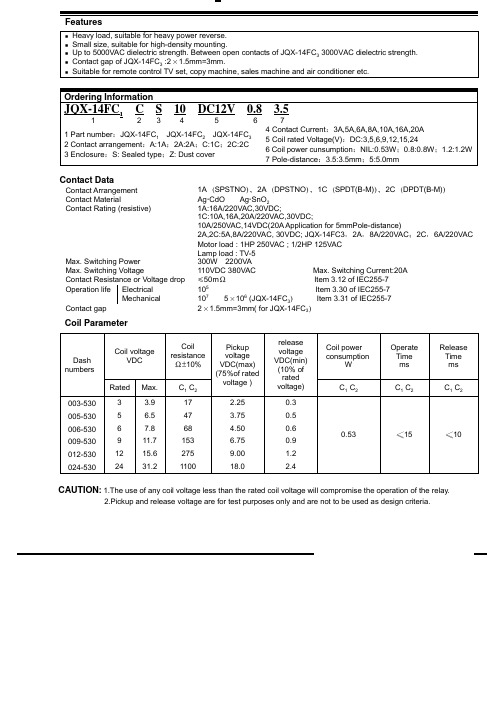
Rated
Max. 7.8 11.7 15.6 19.5 31.2 7.8 11.7 15.6 19.5 31.2
C3 54 100 180 270 740 40 70 120 180 470
voltage )
rated voltage) 2A 0.6 0.9 1.2 1.5 2.4 2C 0.6 0.9 1.2 1.5 2.4
-25~75(JQX-14FC3
Qualification inspection:
Perform the qualification test as specified in the table of IEC255-19-1 and minimum sample size 24.
Safety approvals Safety approval Load
2.Pickup and release voltage are for test purposes only and are not to be used as design criteria.
Operation condition
Insulation Resistance Dielectric Strength Between contacts Between contact and coil Creepage distance Shock resistance Vibration resistance Terminals strength Solderability Ambient Temperature Relative Humidity Mass 1000M min (at 500VDC) JQX-14FC3 3000V 4000v Surge voltage 12kV Item 7 of IEC255-5 Item 6 Item 6 of IEC255-5 of IEC255-5
JQX-10F通用型小型大功率电磁继电器
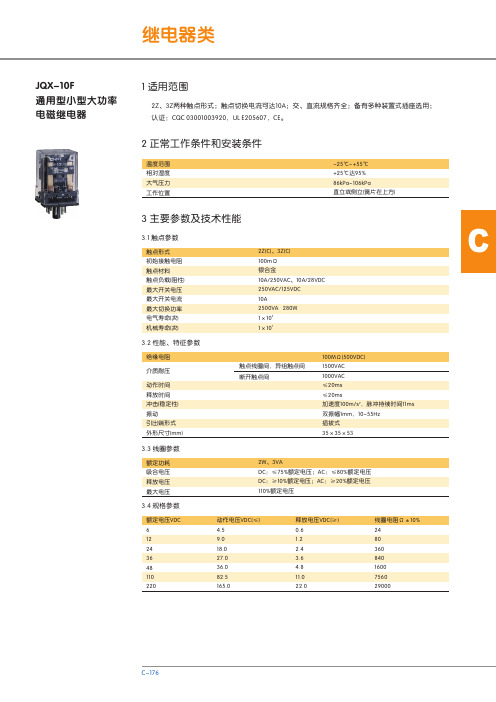
CJQX-10F通用型小型大功率电磁继电器2Z、3Z两种触点形式;触点切换电流可达10A;交、直流规格齐全;备有多种装置式插座选用;认证:CQC 03001003920,UL E205607,CE。
温度范围相对湿度大气压力工作位置-25℃~+55℃+25℃达95%86kPa~106kPa直立或侧立(簧片在上方)触点形式初始接触电阻触点材料触点负载(阻性)最大开关电压最大开关电流最大切换功率电气寿命(次)机械寿命(次)2Z(C)、3Z(C)100mΩ银合金10A/250VAC、10A/28VDC250VAC/125VDC10A2500VA 280W51×1071×103.3 线圈参数3.4 规格参数额定功耗吸合电压释放电压最大电压2W、3VADC:≤75%额定电压;AC:≤80%额定电压DC:≥10%额定电压;AC:≥20%额定电压110%额定电压额定电压VDC612243648110220动作电压VDC(≤)4.59.018.027.036.082.5165.0释放电压VDC(≥)0.61.22.43.64.811.022.0线圈电阻Ω±10%248036084016007560290003.2 性能、特征参数绝缘电阻介质耐压动作时间释放时间冲击(稳定性)振动引出端形式外形尺寸(mm)触点线圈间,异组触点间断开触点间100MΩ(500VDC)1500VAC1000VAC≤20ms≤20ms2加速度100m/s,脉冲持续时间11ms双振幅1mm,10~55Hz插拔式35×35×533.1 触点参数1 适用范围2 正常工作条件和安装条件3 主要参数及技术性能4 配套插座(备选)额定电压VAC 6122448110220380动作电压VAC(≤)4.89.619.238.488.0176.0304.0释放电压VAC(≥)1.22.44.89.6224476线圈电阻Ω±10%7198040016007300225005 外形及安装尺寸2Z:二组转换3Z:三组转换-:直流直流6~220V 交流6~380VCZF08A-E 52×41×21.5JQX-10F/2Z CZF08A 52×41×21.5螺钉型接线端子(装置式、导轨式)继电器型号配用插座型号插座外形尺寸(mm)插座引线形式CZF11A-E 52×44×31JQX-10F/3Z CZF11A 52×44×31螺钉型接线端子(装置式、导轨式)继电器型号配用插座型号插座外形尺寸(mm)插座引线形式6 订货须知。
jqx-15f系列继电器

规格序号
线圈电压 额定值
005
5
006
6
009
9
012
12
015
15
018
18
024
24
048
48
110
110
订货示例
JQX-15F / 006 - 1H 64
陕西群力电工有限责任公司
通讯地址: 陕西省宝鸡市陈仓区群力路 1 号 邮政编码:721300
线圈电阻 (Ω)±10%
27 40 97 155 256 380 660 2560 13450
JQX-15F 型小型大功率通用电磁继电器
该产品为小型大功率通用继电器,主要供空 调、磁卡电表用。
环境条件
温度范围
相对湿度
振动
破坏性 非破坏性
冲击
破坏性 非破坏性
技术特性
-55℃ — 85℃ 40℃时达 98%
10 — 55HZ,1.65mm 双振幅
98 m/s2
触点形式 接触电阻(Ω)
触点间
绝缘电阻 触点组间 (MΩ) 触点线圈间
其它 触点间
介质耐压 Vr.m.s. (50 Hz)
规格表
触点组间 触点线圈间 其它
1H,1D,1Z ≤5
≥1000 ——
≥1000 ≥1000
1500
——
引出端 1:1500;引出端 64:2500 引出端 1:1500;引出端 64:2500
动作时间 释放时间
触点负载 及寿命
外形尺寸 线圈功耗(W) 重 量(g)
电话: 0917-6293792 6293443 6293449 传真: (0917)-6293987
外形尺寸及底视电路图
正泰产品系列类别剖析
万能式断路器
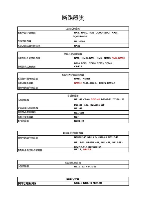
系列万能式断路器
NA8、NA8G、NA1・2OOO-63OO、NA15、D\V15.DW16.
DW17D
万能式断路器
NA1-1000
系列万能式真空断路器
NAK1
塑料外壳式断路器
系列型料外壳式断路器
NM8、NM8S. NM7、NM6、NM6S.NM1. NM10.
DZ20. DZ15、DZ108. DZ253. DZ948
超小型中功率电磁继电器
JZC-32F
小型大功舉电磯继电器
JQX-15F>JQX-16F . JQX-102F . JQX・21F、
JQX・115F、JQX43Fs JQX・13FA、JZX-22F
小型继电器插座系列
时间继电器
系列时间继电器
NJS6. NJS2> NJSK NTE8. JSS48A> JSZ3. JSZ4、
交流弧焊机
系列交流弧焊机BX1、BX3.BX6
宜流弧焊机
系列宜流弧焊机
ZX5、ZX6、ZX5G
系列逆变式宜流电焊机
ZX7
系列交宜流弧焊机
ZXE1
电阻弧焊机
系列脚踏时控点焊机
DN
系列对焊机
UN1
自动半自动弧焊机
系列CO2气体保护弧焊机
NBC
直流铝极氨弧焊机
VVS
系列逆变式直流氨弧焊机
WS
系列宜流脉冲氮弧焊机
型普通整流管
ZPx
型普通晶闸管
KP
型双向晶闸管
KS
型快速整流管
ZK
型快速晶闸管
KK
接线端子
系列
JF5、SAK、JXB、JCUK.JH1.JH2.JH5.JH6、TD、JH9. JH1O. NJDx TK. TB. TC、H、TZ1. DI、JX2、JDO. MJ、TH35・7・5(C45)
JGCS产品描述

产品描述(送试样品)
屉分为1/2单元、1单元、2单元、3单元等系列,单元回路额定电流在400A及以下。相同规格的单元可互换。1/2单元抽屉与电缆室的转接采用背板式结构,功能单元抽屉与电缆室的转接采用棒式或管式结构。馈电柜和电动机控制柜设有专用的电缆室,为了便于功能单元与电缆室内电缆的安装与维修。柜体的保护导体装于柜体底部并与金属框架可靠连接,整个柜体构成完整的接地保护回路。柜体所有金属部件均有防护措施,镀锌或环氧粉末静电喷涂,门、侧板、顶板、顶盖等可见部分采用环氧粉末静电喷涂。母线采用高强度绝缘母线夹固定在柜体上。
2》主要技术参数
额定工作电压:AC380V。
额定绝缘电压:AC660V。
额定频率:50Hz。
过电压类别:1)Ⅰ□,Ⅱ□,Ⅲ■,Ⅳ■
注:如提供的样柜有不同的安装类别应予以说明。
材料组别:Ⅲa
工厂编号:A1CN28254
产品描述(送试样品)
注:注:应提供最底材料组别。
污染等级:3级别
电气间隙:水平母线,垂直母线,分支母线和主电路接插件带电部件之间及其与接地金属构件间不小于20mm;功能单元中带电部件,不同极性的裸露带电部件之间不小于8mm;裸露带电部件对金属件之间不小于10mm。
1)产品型号及名称:GCS-50kA-2500A低压抽出式开关柜。
2)提供图纸及编号:
试样总装配图:JL-GCS-01
试样主电路图:OYK.392.001
3)主要结构数据:
外型尺寸:#1柜2200×800×1000mm;2#柜2200×800×1000mm;
3#柜2200×800×1000mm。
绝缘夹块之间的最大距离:800mm。
1》产品构成的描述及结构特点(结构概要说明):
JQX-13FA 小型大功率电磁 继电器 说明书

2 正常工作条件和安装条件20A触点切换能力;交/直流规格齐全;透明防尘罩封装,安装方式多样;备有各种插座选用;可选带状态指示灯的规格。
JQX-13FA小型大功率电磁继电器3.3 线圈参数3.4 规格参数额定功耗吸合电压释放电压最大电压0.9W、1.2VADC:≤75%额定电压;AC:≤80%额定电压DC:≥10%额定电压;AC:≥20%额定电压110%额定电压温度范围相对湿度大气压力工作位置-30℃~+60℃+40℃达90%86kPa~106kPa 任意额定电压VDC 5612243648110127220动作电压VDC(≤)3.754.59.018.027.036.082.595.3165.0释放电压VDC(≥)0.50.61.22.43.64.811.012.722.0线圈电阻Ω±10%2844160640144025601450017000390001H(A)、1D(B)、1Z(C)100mΩ银合金20A/220VAC、20A/28VDC 250VAC/125VDC 20A4400VA 560W 51×1071×103.2 性能、特征参数绝缘电阻介质耐压动作时间释放时间冲击(稳定性)振动引出端形式外形尺寸(mm)线圈轭轶间,异组触点间断开触点间100MΩ(500VDC)1500VAC 1000VAC ≤25ms ≤25ms2加速度100m/s ,脉冲持续时间11ms 双振幅1mm,10~55Hz 插拔式、PCB式27.5×21.5×35.5触点形式初始接触电阻触点材料触点负载(阻性)最大开关电压最大开关电流最大切换功率电气寿命(次)机械寿命(次)3.1 触点参数1 适用范围3 主要参数及技术性能额定电压VAC 612243648110127220380动作电压VAC(≤)4.89.619.228.838.488.0101.6176.0304.0释放电压VAC(≥)1.22.44.87.29.62225.44476线圈电阻Ω±10%10.5441803806503670410014500390004 配套插座(备选)继电器型号配用插座型号插座外形尺寸(mm)插座引线形式CZT08A -E 79×29×33JQX -13FA螺钉型接线端子(装置式、导轨式)5 外形及安装尺寸注:对于订货示例中引出端形式为单引出规格,只保留端子编号2、3、6、7、8的引出端。
宏发115f继电器的说明书

宏发115f继电器的说明书宏发115F继电器说明书第一章:产品概述宏发115F继电器是一种高性能、高可靠性的电气开关设备。
它采用先进的电磁原理,可以将微弱的控制信号(通常为毫安级别)转换成大电流的输出信号,用于控制各种电气设备的启停和方向变换。
本继电器具有安装简便、体积小巧、操作可靠等特点。
第二章:型号与规格宏发115F继电器提供多种型号和规格,以满足不同的用户需求。
主要规格包括:负荷电压、负荷电流、接线方式、工作温度范围等。
用户在选型时应根据具体需求综合考虑各项指标,选择适合的型号。
第三章:安装与连接1. 安装要求:宏发115F继电器适用于安装在干燥、无腐蚀性气体的室内环境中。
在安装时应注意保持良好的通风和散热条件。
2. 连接方式:本继电器支持多种接线方式,包括直流串联、直流并联、交流系列、交流并联等。
用户应根据实际应用需求选择合适的接线方式,并按照图示正确连接。
第四章:操作与维护1. 操作注意事项:在进行操作时,用户应先确保继电器的控制信号和电源电压是否符合要求,以保证正常工作。
操作时应轻拿轻放,避免碰撞和振动。
2. 维护保养:宏发115F继电器采用密封结构,无需定期保养。
但在使用过程中,应定期检查接线是否松动,继电器表面是否有灰尘积聚,并及时清理。
第五章:故障排除与常见问题解答1. 继电器无法工作:可能是控制信号不稳定、电源电压不足等原因造成的。
用户应检查控制信号和电源电压是否正常,如有异常应进行排除。
2. 继电器发热过高:可能是负荷过大、外界温度过高等原因导致的。
用户应重新评估负荷和环境条件,避免长时间超负荷运行。
第六章:安全警示与注意事项1. 本继电器仅适用于低压电路,禁止直接接触高压电源。
2. 在拆卸和维修继电器时,应确保断开电源,避免触电危险。
3. 禁止将本继电器用于超出规定范围的工作条件下,以免损坏设备和引发安全事故。
第七章:环保与回收宏发115F继电器采用环保材料制造,符合国家相关法规和标准,环境友好。
系统传感器1151低厚型电离侦测氛气设备说明书
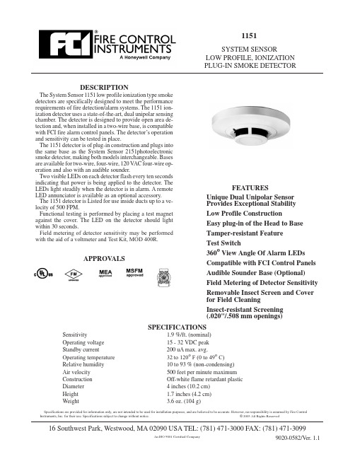
DESCRIPTIONThe System Sensor 1151low profile ionization type smoke detectors are specifically designed to meet the performance requirements of fire detection/alarm systems.The 1151ion-ization detector uses a state-of-the-art,dual unipolar sensing chamber.The detector is designed to provide open area de-tection and,when installed in a two-wire base,is compatible with FCI fire alarm control panels.The detector’s operation and sensitivity can be tested in place.The 1151detector is of plug-in construction and plugs into the same base as the System Sensor 2151photoelectronic smoke detector,making both models interchangeable.Bases are available for two-wire,four-wire,120V AC four-wire op-eration and also with an audible sounder.Two visible LEDs on each detector flash every ten seconds indicating that power is being applied to the detector.The LEDs light steadily when the detector is in alarm.A remote LED annunciator is available as an optional accessory.The 1151detector is Listed for use inside ducts up to a ve-locity of 500FPM.Functional testing is performed by placing a test magnet against the cover.The LED on the detector should light within 30seconds.Field metering of detector sensitivity may be performed with the aid of a voltmeter and Test Kit,MOD 400R.APPROV ALSSPECIFICATIONSSensitivity1.9%/ft.(nominal)Operating voltage 15-32VDC peak Standby current200uA max.avg.Operating temperature 32to 120o F (0to 49o C)Relative humidity 10to 93%(non-condensing)Air velocity 500feet per minute maximum Construction Off-white flame retardant plastic Diameter 4inches (10.2cm)Height 1.7inches (4.2cm)Weight3.6oz.(104g)1151SYSTEM SENSORLOW PROFILE,IONIZATION PLUG-IN SMOKE DETECTOR9020-0582/Ver.1.116Southwest Park,Westwood,MA 02090USA TEL:(781)471-3000FAX:(781)471-3099Specifications are provided for information only,are not intended to be used for installation purposes,and are believed to be accurate.However,no responsibility is assumed by Fire Control Instruments,Inc.for their use.Specifications subject to change without notice.©2003All Rights ReservedFEATURESUnique Dual Unipolar Sensor Provides Exceptional Stability Low Profile ConstructionEasy plug-in of the Head to Base Tamper-resistant Feature Test Switch360o View Angle Of Alarm LEDs Compatible with FCI Control Panels Audible Sounder Base (Optional)Field Metering of Detector Sensitivity Removable Insect Screen and Cover for Field CleaningInsect-resistant Screening (.020"/.508mm openings)An ISO 9001CertifiedCompanyMOUNTINGOn a4-inch square box with or without plasterring.Minimum depth1.5inches.On a3.5-inch octagonal box.Minimum depth1.5inches.INSTALLATIONPlace the detector into the detector base.Turn the de-tector clockwise until the detector locks into place. To use the tamper-proof feature,break the smaller tab on the scribed line in the tamper proof tab located on the detector mounting bracket.Install the detector.To re-move the detector from the base when using the tam-per-proof feature,insert the blade of a small screwdriver into the hole on the side of the base and push the plastic lever away from the detector head.This will allow the detector to be rotated counterclockwise for removal.NOTE:The decorative ring must be re-moved in order to remove the head when using the tam-per-proof feature.The tamper-proof feature may be defeated perma-nently by breaking the plastic lever off the base. NOTE:The number of two-wire smoke detectors which can be accommodated per zone varies with dif-ferent control panels.Consult the control panel in-struction manual to determine the capacity.Refer to NFPA72,Chapter5-3,“Smoke Sensing Fire Detectors”for spacing,location of detectors and other guidelines.TESTINGDetectors may be tested in the following ways: Place a test magnet against the detectoras directed in the installation instructions.The detector should go into alarm within30seconds.Field metering of detector sensitivity may beperformed with the aid of a voltmeter and Test Kit,MOD400R.For the complete procedure,refer to the Installation and MaintenanceInstructions furnished with each detector.MAINTENANCECleaning programs should be adapted to the individ-ual environment.We recommend at least an annual cleaning of the unit.The detector screen and cover as-sembly can be removed,revealing the sensing cham-ber.A vacuum cleaner can be used to remove dust from the screen,cover and sensing chamber.For the com-plete procedure,refer to the Installation and Mainte-nance Instructions furnished with each detector.2of29020-0582 ORDERING AND TECHNICAL INFORMATIONModel Contacts Description1151Ionization DetectorB110LP Base,Two-wireB112LP Form A&C Base,four-wire,24VDC operationB114LP Form A,C&Supv.Base,four-wire,120V AC operationB401BH Base,four-wire,with audible sounderRA-400Z Remote Alarm IndicatorPAM-1Form B End of Line Relay,24VDCMOD400R Test Kit。
CJX2-F系列交流接触器
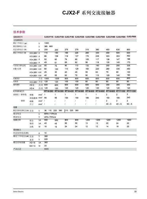
0
00
600
600
0
0
RT6-355 RT6-45
00 600 0 RT6-500
80 600 0 RT6-630
80 600 0 RT6-800
80 300 0 RT6-800
80 300 0 RT7-000
80 300 0 RT7-50
延时范围 0.1-3S 0.1-30S 10-180S 0.1-3S 0.1-30S 10-180S
订货编码 SK420 SK422 SK424 SK430 SK432 SK434
34
Delixi Electric
Delixi Electric
CJX2-F 系列交流接触器
外形及安装尺寸
■ CJX-F5~330外形及安装尺寸
80 0~0
CJX-F50 67 7 7 40 0 M8 3 47 4 07 0 5
80 0~0
CJX-F85 7 74 83 40 0 M8 3 54 7 3.5 0 5
80 0~0
CJX-F5 7 97 83 48 5 M0 3 7 7 3.5 0 5
*
C
0
0
380
F
M
Q
注:除额定电流5A、50A这两种规格外,其余规格的线圈电压无36V
36
Delixi Electric
AC-5 VA 360 DC-3 W 33
CCC
Delixi Electric
33
CJX2-F 系列交流接触器
附件
F4 顶辅助触头
极数
触头形式
NO
NC
1
1
2极
0
2
2
0
0
- 1、下载文档前请自行甄别文档内容的完整性,平台不提供额外的编辑、内容补充、找答案等附加服务。
- 2、"仅部分预览"的文档,不可在线预览部分如存在完整性等问题,可反馈申请退款(可完整预览的文档不适用该条件!)。
- 3、如文档侵犯您的权益,请联系客服反馈,我们会尽快为您处理(人工客服工作时间:9:00-18:30)。
Surge voltage between coil and contacts Operate time (at nomi. Volt.) Release time (at nomi. Volt.) Temperature rise (at nomi. Volt.) Functional Shock Resistance Vibration Resistance Humidity Ambient temperature Termination Unit weight Construction Destructive
CONTACT DATA
Contact Arrangement Initial Contact Resistance Max. Contact Material Max. switching voltage Max. switching current 1A, 1C 50m (at 1A/ 6VDC) See ordering info. 440VAC/ 125VDC 16A 2500VA 10A/ 250VAC Contact Rating 1 x 10⁵OPS(360 ops/hour) 16A/ 250VAC 5 x 10 OPS(360 ops/hour) Mechanical life Electrical life 1 x 10⁷OPS (72,000 ops/hour) 1 x 10⁵OPS (360 ops/hour)
4
COIL
Coil power JQX-115F-TH:0.25W, JQX-115F-T:0.4W
COIL DATA
Nominal Voltage VDC 5 6 9 12 18 24 Standard (JQX-115F-T) Max. Pick-up Drop-out allowable Voltage Voltage Voltage VDC VDC VDC(at 20 ) 3.50 4.20 6.30 8.40 12.6 16.8 33.6 42.0 0.5 0.6 0.9 1.2 1.8 2.4 4.8 6.0 6.5 7.8 11.7 15.6 23.4 31.2 62.4 78 Coil Resistance (at 20 ) 62 90 202 360 810 1440 5760 7500 10% 10% 10% 10% 10% 10% 10% 15%
1H
S
3
A
Coil voltage
Contact arrangement Structure Version
S: Sealed IP67 3: 5.0mm A: AgSnO2
Nil: Unsealed
Contact Material
B: AgNi
Nil: AgCdO
OUTLINE DIMENSIONS, WIRING DIAGRAM AND PC BOARD LAYOUT
元器件交易网
JQX-115F-T/TH
MINIATURE HIGH POWER RELAY
Features
* High Temperature 105 * Low height 15.7 mm File No.:116934 * 5KV dielectric coil to contacts * Creepage distance 10mm * Sealed IP67& unsealed types available File No.:CQC02001001951
18 24 48 60
SAFETY APPROVAL RATINGS
JQX-115F-TH (High Temp and High Sensitive) Specifications VDE JQX-115F-TH1H(S)3(G)(F) Ratings 10A 250VAC @ to105°C 6A 400VAC @ to105°C
48 60
Байду номын сангаас
Sensitive (JQX-115F-TH) Nominal Voltage VDC 5 6 9 12 Pick-up Voltage VDC 3.75 4.50 6.75 9.00 13.50 18.00 36.00 45.00 Max. Coil Drop-out allowable Resistance Voltage Voltage (at 20 ) VDC VDC(at 20 ) 0.5 0.6 0.9 1.2 1.8 2.4 4.8 6.0 6.5 7.8 11.7 15.6 23.4 31.2 62.4 78 100 144 324 576 1,296 2,304 9,216 12,857 10% 10% 10% 10% 10% 10% 15% 15%
1000 3.6 3.4
COIL OPERATING RANGE DC
Operations (X10000 OPS)
Coil Voltage(U/UN)
100
3.0 2.6 2.2 1.8 1.4 1.0
10
10 A
1 0 2 4 6 8 10 12 14 16 18 20
0.6 0 +20 +40 +60 +80 +100 +120
Contact Current (A)
Ambient Temperature(
)
93
General Purpose Power Relays JQX-115F-T/TH
Max. switching power
CHARACTERISTICS
Initial Insulation Resistance Dielectric Between coil and Contacts Strength Between open contacts 1000M , 500VDC 5000VAC 1min. 1000VAC 1min. 10KV (1.2X50µs) Max. 15ms Max. 8ms Max. 55 100 m/s2 1000 m/s2 10 to150Hz , 10g/5g 35% to 85% -40 to +105 PCB 13.5g Sealed IP67 &Unsealed
HONGFA RELAY ISO9001*ISO/TS16949 *ISO14001 CERTIFIED
VERSION: EN02-20040601
92
元器件交易网
ORDERING INFORMATION
JQX-115F-T/TH 012
Type
JQX-115F-TH Sensitive 0.25W 5, 6, 9,12, 18, 24, 48, 60VDC 1H: 1 Form A 1Z: 1 Form C
Outline Dimensions
General Purpose Power Relays JQX-115F-T/TH
PCB layout
5.04 5.04
Wiring Diagram (1 Form A) (1 Form C)
20.16
CHARACTERISTICS CURVE
LIFE CURVE
