飞康 VTL安装手册
VTL软件安装及配置指南
浪潮虚拟磁带库VTL1000软件安装指南1.硬件平台及软件要求硬件平台为AS500N,前两个盘位做RAID1,安装 Update2 X86_64系统。
Raid1大小为470000M安装CentOS时,具体的分区情况为:boot 239988M/ 222000MSwap 8000MCentOS必选包为Xwindows SystemGNOME Desttop EnvironmentApplications:EditorsServers:Server Configuration ToolsMail ServerDNS Name ServerPostgre SQL DatabaseNetwork Server(iscsi-initiator软件包)DevelopmentDevelopment ToolsSystemAdministrator ToolsSystem Tools(sysstat软件包)Campatibility Arch Support安装完CentOS后重新引导并进入系统!!设置系统root帐号的密码为root软件安装将软件光盘放入光驱,挂载光盘#mount /dev/cdrom /mnt.安装VTL软件默认的安装目录时/usr/local/vtl,安装日志存放在/usr/local/vtl-archive下,在此文件目录下,即为安装过程记录文档,如果需要查看安装过称,可以用命令#less 查看。
#cd /mnt#sh vtlinstall当出现如下时,输入Y,并按回车继续安装。
出现输入Luns数时,如图,键入16或是32,即设定磁盘划16或是32个lun当出现如下图示时,默认选择回车继续,表示此文件系统只有一个。
系统要求选择光纤HBA卡型号target驱动时,由于此VTL需要安装完之后打补丁,所以现在不需要选择具体的FC HBA卡的型号,所以我们选择:q,表示没有光纤target模块的支持。
FLIR Navigator II 安装说明书
The Navigator II imaging system is controlled by US export laws. There are special versions of this system that are approved for international distribution and travel. Please contact FLIR Systems if you have any questions.
Navigator™ II
Installation MANUAL
For Static and Pan / Tilt Configurations
Document Number: 432-0001-00-12, rev 100
© FLIR Systems, Inc., 2008. All rights reserved worldwide. No parts of this manual, in whole or in part, may be copied, photocopied, translated, or transmitted to any electronic medium or machine readable form without the prior written permission of FLIR Systems, Inc.
Camera Mounting
Caution! Mount your Navigator II with the pedestal sealed to a flat, horizontal surface with the camera above the mounting plane. Any other type of installation is not appropriate, may result in damage to the camera, and may void the warranty.
VTL软件安装及配置指南
VTL软件安装及配置指南VTL(Virtual Tape Library)软件是一种虚拟磁带库软件,用于模拟磁带库的功能,可以将数据备份到磁带上。
本文将介绍VTL软件的安装和配置步骤,以帮助用户快速上手。
3.执行安装程序。
进入解压后的目录,找到安装程序,并以管理员身份运行。
根据安装程序的提示,选择合适的安装选项,如安装路径、开始菜单的快捷方式等。
4.确认安装完成。
安装过程中,会显示安装进度和完成信息。
待安装完成后,关闭安装程序。
完成了VTL软件的安装后,接下来需要进行相应的配置。
1.启动VTL软件。
在安装目录中找到启动程序,双击运行。
启动后,VTL软件的控制台界面会显示出来。
2.创建虚拟磁带库。
在控制台界面上,选择“设备管理”或类似的选项。
点击“新建”按钮,按照要求填写磁带库的名称、路径、容量等信息,并点击“确定”按钮保存配置。
3. 配置备份软件。
根据实际情况,选择合适的备份软件,如Veritas NetBackup、IBM Tivoli等,然后进入相应的配置界面。
4.添加磁带库。
在备份软件的配置界面上,找到“设备”或类似的选项,点击“添加”按钮。
选择虚拟磁带库,并填写相应的配置参数,如磁带库的名称、IP地址、端口号等。
5.测试备份操作。
完成磁带库的添加后,可以进行备份操作的测试。
根据备份软件的要求,选择相应的文件或目录,并进行备份操作。
在备份过程中,可以观察备份数据的传输速度、备份进度等信息。
6.验证备份数据。
备份完成后,可以对备份的数据进行验证,以确保备份的正确性。
选择备份软件的验证功能,按照要求对备份数据进行验证操作。
根据验证结果,可以判断备份操作的成功与否。
完成了配置后,就可以开始使用VTL软件进行备份操作了。
在实际操作中,还需要注意以下几点:1.定期进行备份操作。
为了保证数据的安全性,建议定期进行备份操作,避免数据的丢失或损坏。
2.注意备份数据的选择。
在进行备份操作时,应该选择重要的数据进行备份,如公司文件、数据库等,以免造成不必要的数据损失。
Falcorn IPStor VTL安装步骤
Falcorn IPStor VTL安装步骤1. 在安装Redhat 7.3的VmWare过程中,SCSI适配器类型选择LSI。
2. 执行ipstorcheck,检查ITStor的安装环境是否满足:ipstorcheck在安装光盘的Server/Linux目录下。
如果提示那个软件包没有安装,用rpm指令在安装缺少的软件包。
3. 执行IPStor安装。
IPStor的安装过程分为两个步骤:a) 首先执行ipstorinstallb) 重启后,IPStor会自动进行配置。
c) 成功安装后启动的Redhat界面:4. 安装和配置IPStor SAN Clienta) 执行IPStor SAN客户端安装。
b) 打开IPStor SAN Client监视器。
c) 添加ITStor VTL服务器d) 启动IPStor SAN Client。
5. 配置IPStor磁带库资源a) 为IPStor的VmWare服务器增加多一个磁盘,作为虚拟磁带库的存储空间。
b) 安装IPStor管理界面,然后登陆。
c) Enable iSCSI、VirtualTape Library资源。
d) 添加物理磁盘资源∙选择Storage Device,然后点击鼠标右键。
∙选择设备准备的模式,下一步。
∙选择Unassigned的磁盘设备,下一步。
Review选择的设备,点击Finish。
∙设备Assign过程会删除磁盘上所有数据,确实是否接受。
填写Yes进行确认。
∙查看设备Assign状态。
e) 创建虚拟磁带库资源。
∙指向Virtual Tape Library System,点击鼠标右键,出现Configuration Wizard。
∙下一步,开始配置虚拟磁带库。
∙选择虚拟带库厂家和配置磁带库名称。
∙选择磁带机型号和配置磁带机名称。
∙配置磁带归档和复制选项。
∙配置条码阅读器的开始和结束编号。
∙选择磁带容量按需分配,动态增长。
∙查看配置信息,点击Finish完成虚拟磁带库配置过程。
Module 3-1 VTL6900 系统安装

Copyright © 2010 Huawei Technologies Co., Ltd. All rights reserved.
操作系统安装—设置系统启动顺序
重启设备;
当KVM上出现右侧
界面时,按F12, 稍候系统将进入
boot manager界面
Copyright © 2010 Huawei Technologies Co., Ltd. All rights reserved.
引擎后面板重要接口示意图
Copyright © 2010 Huawei Technologies Co., Ltd. All rights reserved.
Page 3
产品系统安装前准备
VTL6900系统安装前准备
拆除10GE/GE扩展网卡 --系统安装之前,需要将扩展的10GE网卡或GE网卡拆除,否则安装完成后 网口编号混乱 安装FC HBA 连接KVM --将引擎与KVM连接,包括VGA接口和连接鼠标键盘的USB端口;
VTL6900产品系统安装介绍
Copyright © 2010 Huawei Technologies Co., Ltd. All rights reserved.
目标
学完本课程后,您将能够:
掌握VTL6900系统安装方法及步骤;
Copyright © 2010 Huawei Technologies Co., Ltd. All rights reserved.
Copyright © 2010 Huawei Technologies Co., Ltd. All rights reserved.
Page 5
VTL-S 安装配置文档
VTL-S 安装配置文档一.VTL-S安装1.硬件基本要求a. 229 with 12GB RAMb. 2.5TB total storage capacityc. Recommend RAID set configure with 7 physical luns: (example below, 750GB*6, R5)7 luns will be used for OS(50GB), VTL (1TB),SIR_index (300GB) and SIR_Data_repository(600GB * 4 luns)2.安装Redhat AS 4 U2 x86-643.安装VTL-Sa. ./vtlinstall (或者sh vtlinstall)按提示确认b. options scsi_mod max_luns=10这里要注意!要大些的值c.2200) QLogic 22xx (ISP2200) host adapter family2300) QLogic 2300 (ISP2300 and ISP2312) host adapter family2322) QLogic 2322 (ISP2322) host adapter family2400) QLogic 2400 (ISP2422 and ISP2432) host adapter familyq) No Fibre Channel target mode supportSelect HBA class:这里选择光纤卡,注意VTL只支持QLogic的光纤卡d. Do you want to configure NTP (Network Time Protocol) service on this appliance (Y or N)?多台复制需要配置时间服务器e.Configuration Summary---------------------Server Installation Type: Upgrade options scsi_mod max_luns=20options sd_mod max_scsi_disks_fs=10Target Mode HBA Support: DisabledNTP Service: EnableEnter 'Y' to accept configuration or enter 'N' to change configuration:选择Y,完成安装4.配置VTL-S (基本配置)a. 右击服务器图标→选择license输入注册码b. 选择Physical Resources → Storage devices → SCSI devices → enlist(需要enlist 才能被VTL使用)c. 选择VirtualTape Library Systemnew →创建虚拟带库,驱动器和磁带d. 右击服务器图标→选择options →起用iscsi 和fce. 创建SAN Client 或者使用everyone_Iscsi,指派已经创建的带库到Client5.配置VTL-S (启用De-duplication)a. 右击服务器图标→选择options → enable local SIR按提示完成操作,SIR_index (300GB) and SIR_Data_repository(600GB * 4 luns)系统会建立对应的SAN Resources6.配置VTL-S (配置远程复制)a. 右击服务器图标→选择SIR → Replication → Add VTL Target根据提示完成操作b.选择磁带→右击选择Replication → Add根据提示完成操作c.复制完成后,另一方的Replication Resources 会出现一个标记的记录,同时Virtual Vault会出现一个复制过来的磁带7. callhome 功能a. 右击服务器图标→选择options → enable callhomeb. 根据需要指定不同的callhome策略8. 控制台结构a. VirtualTape Library System objecta.1 Virtual Tape LibrariesThis object lists the virtual tape libraries that are currently available. Each virtual tape library consists of one or more virtual tape drives and one or more virtual tapes.Each virtual tape library and drive can be assigned to one or more backup servers Each library’s virtual tapes are sorted in barcode order.注意:barcode 是一个重要的概念,他用来标识不同的磁带a.2 Virtual VaultList the virtual tapes that are currently in the virtual vault.The virtual vault is a tape storage area for tapes that are not inside a virtual tape library.a.3 Import/ExportThis object lists the import and export jobs that have been submitted.If needed, youcan cancel a pending job from here. You can have up to 32 concurrent import/export jobs running, depending on the number of physical tape drives attached to your VTL.a.4 Physical Tape LibrariesThis object lists the physical tape libraries that are available to VTL.a.5 Replica ResourcesThis object lists the Replica Resources that are on this VTL server.a.6 DatabaseThis object contains configuration information for the VTL.b. SAN Resources objectSAN resources are the virtualized disks that have been configured as the SIR index resource, SIR scratch resource, and SIR configuration repository resource on the VTL server.c. SAN Clients objectSAN clients are the backup servers that use the VTL. VTL supports Fibre Channel and iSCSI backup servers. For client configuration information, refer to theappropriate sections in this guide.d. Reports objectVTL provides reports that offer a wide variety of information:• Throughput• Physical resources - allocation and configuration• Disk space usage• F ibre Channel adapters configuration• Replication status• Virtual tape/library information• Job statuse. Export datafrom a report, you can save the data from the server and device throughput and usage reports.The data can be saved in a comma delimited (.csv) or tab delimited (.txt) text file. Toexport information, right-click on a report that is generated and select Export.f. Physical Resources objectPhysical resources are all of your adapters/FC HBAs and storage devices. Harddisks are used for creating virtual tape libraries/drives and virtual tapes.详细配置文档请参考光碟自带的PDF。
飞康VTL虚拟磁带库解决方
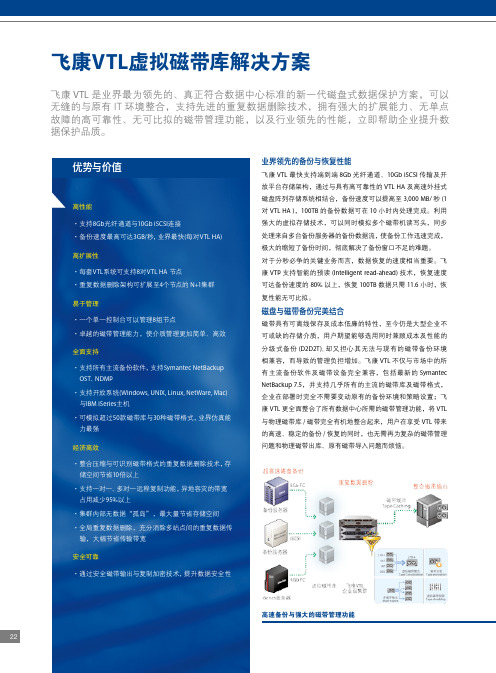
22高速备份与强大的磁带管理功能·集群内部无数据“孤岛”,最大量节省存储空间·全局重复数据删除,充分消除多站点间的重复数据传输,大幅节省传输带宽安全可靠·通过安全磁带输出与复制加密技术,提升数据安全性先进的重复数据删除技术全面兼顾性能、可靠性与成本重复数据删除不能影响备份性能信息系统内储存的数据有相当多的部分都是重复的,其中又以备份数据的重复比例最高。
飞康VTL企业版整合了革命性的重复数据删除技术–单实例存储(SIR),当备份数据写入VTL后,经过SIR的分析比对,只保留唯一不重复的单元,同时删除所有冗余的数据,仅保留容量极小的索引供数据恢复使用。
重复数据删除后节省出的空间,可以用来保存更多的虚拟磁带和周期更长的备份数据。
飞康VTL支持在线去重、并发去重、后处理及不去重四种重复数据删除策略,充分满足用户环境中各种不同类型数据的不同备份需要。
将备份操作和重复数据删除操作分离,因而完全不会影响备份的性能,还可视应用与备份策略的需要,灵活的调整、启动重复数据删除的时机,因此无论是用于高性能海量备份,还是用于小数据量简单环境备份,都能以最小化的成本换取最高的部署灵活性、弹性与备份恢复性能。
飞康VTL将硬件压缩与可识别磁带格式技术相结合,有效的缩短了数据处理的时间并提升重复数据删除比率,非常适合用于备份数据量庞大、备份窗口限制较高的大型企业。
集群架构确保可靠性及扩展性飞康VTL支持企业级集群架构,单台设备可以扩充8节点VTL+5节点SIR,集群内所有数据采用无“孤岛”的单实例方式存储。
所有节点都通过同一管理界面进行管理;节点数越多,备份性能及重复数据删除效率越高;其中任何一个节点发生故障,其它节点可以立即接手工作,确保无单点故障发生,完全符合数据中心对系统可用性及可靠性的要求。
支持全域重复数据删除,节省空间、带宽与管理成本飞康VTL可以扩展远程复制功能,用户可以利用WAN广域网络将备份数据复制到远程,实现异地灾备,并可通过加密功能防止数据在网络传输过程中被恶意窃取。
vtl用户手册
公告
本手册中描述的产品特性和规格如有更改,恕不另行通知。 由于使用或按照包含于此的信息执行而导致的任何损害或数据丢失,制造商将不负担任 何责任。
安规信息
适用于欧洲
本设备符合 EMC (电磁兼容性检验) 标准。
Federal Communications Commission (FCC) 声明
本设备经过测试,结果依据 FCC Rules Part 15之规定,符合 Class B 数字装置之标准。这 些标准的设立目的是在安装本设备的居家环境中,针对有害干扰提供合理防护。本设备产生、 使用、而且能辐射无线电频率能量,若未依据指示安装及使用,则对于无线电通讯可能造成有 害干扰,但是亦无法保证特定安装方式不会产生干扰。若本设备对于收音机或电视机的接收讯 号确实造成有害干扰;这种干扰可藉打开及关闭本设备电源加以确认;则我们鼓励使用者采取 下列措施,尝试消除干扰: 改变接收天线的方向或位置。 增加设备与接收机之间的距离。 设备与接收机使用个别的电源插座。 请联系经销商或经验丰富的广播/电视机故障,最好给存储系统配置UPS。在用UPS供电时,应保证UPS启动至少1分钟后再 接通存储系统电源,以避免UPS在刚启动时对存储子系统造成冲击。
5
目
录
序言...................................................................................................................................................1 安规信息...........................................................................................................................................1 安全警告和注意事项.......................................................................................................................2 第一章 SureSave VTL500i/1000i 介绍......................................................................................... 6 1.1 产品概述...........................................................................................................................6 1.2 接口与面板说明............................................................................................................... 7 1.3 现场可更换部件............................................................................................................... 8 第二章 硬件安装与连接.................................................................................................................9 2.1 安全注意事项...................................................................................................................9 2.2 安装条件...........................................................................................................................9 2.3 设备开箱.........................................................................................................................10 2.4 安装到机架..................................................................................................................... 11 2.5 安装磁盘.........................................................................................................................12 2.6 设备连接.........................................................................................................................13 第三章 系统配置...........................................................................................................................16 3.1 基本知识.........................................................................................................................16 3.2 系统配置概要.................................................................................................................17 3.3 基本配置步骤.................................................................................................................18 3.4 存储管理.........................................................................................................................20 3.5 虚拟磁带库管理............................................................................................................. 22 3.6 系统设置.........................................................................................................................27 第五章 注意要点及故障处理....................................................................................................... 31 5.1 注意要点.........................................................................................................................31 5.2 常见故障处理.................................................................................................................31 联系我们.........................................................................................................................................32
飞康VTL企业版白皮书
优势与价值高性能>支持8Gb 光纤通道与10Gb iSCSI 连接 >备份速度最高可达2.8GB/秒,业界最快(每对VTL HA)高扩展性>每套VTL 系统可支持8对VTL HA 节点 >可扩展8个SIR N+1集群节点,提供企业级高可用性及扩展能力易管理性>单一控制台可以管理8组节点>支持磁带缓冲(Tape Caching )、虚拟磁带整合及多磁带输出(Multi-Tape Export )等功能,提升磁带的管理效率无缝兼容>支持所有主流备份软件,包括Symantec NetBackup OST >同时支持开放系统(Windows, UNIX, Linux, NetWare, Mac)与IBM iSeries 主机 >可模拟超过60款磁带库与30种磁带格式,业界仿真能力最强低成本/高效益>整合压缩与可识别磁带格式的重复数据删除技术,存储空间节省10倍以上 >支持一对一、多对一远程复制功能,删除各站点之间的重复数据后,可降低95%异地灾备的网络带宽占用高安全性>通过安全磁带输出(Secure Tape Export )、加密的数据复制,提升磁带安全性,确保数据安全飞康VTL 虚拟磁带库备份速度最快、整合重复数据删除的企业级虚拟磁带库方案,立即提升数据保护的效率与品质飞康VTL 是真正符合数据中心标准的新一代磁盘式数据方案,可以无缝的与原有IT 环境整合,支持先进的重复数据删除技术,拥有强大的扩展能力、无单点故障的高可靠性、无可比拟的磁带管理功能,以及行业领先的性能。
业界领先的备份与恢复性能飞康VTL 最快支持端到端8Gb 光纤通道、10Gb iSCSI 传输及开放平台存储架构,通过与具有高可靠性的VTL HA 及高速外挂式磁盘阵列存储系统相结合,备份速度可以提高至2,800 MB/秒(1对VTL HA ),100TB 的备份数据可在10小时内处理完成。
ICON WESLO 2 健身机操作指南说明书
目 录WESLO 是 ICON IP, Inc. 的注册商标重要注意事项............................................................................................................................................................3用前说明...................................................................................................................................................................5组装..........................................................................................................................................................................6操作与调整..............................................................................................................................................................12如何折叠和移动跑步机............................................................................................................................................18故障检修.................................................................................................................................................................20锻炼指导.................................................................................................................................................................22零件清单.................................................................................................................................................................24分解图.....................................................................................................................................................................25售后服务..............................................................................................................................................................封底有限担保..............................................................................................................................................................封底1.产品所有人有责任确保所有跑步机使用者都充分了解所有的警告和注意事项。
NetStor VTL150G3 快速安装指南V1.0
NetStor® VTL 150G3 快速安装指南
第 1 章 警告和注意事项
本章节包含在安装使用 Netstor VTL 150G3 虚拟磁带库之前以及在安装 使用过程中需要注意的一些事项。请仔细阅读并严格遵守本手册中的所有警 告标识和注意事项。如果存在任何疑问,请与同有技术咨询部门联系。
1.1 警告
静电保护
本手册中所有操作必须在具有静电保护的工作台上执行,因为虚拟磁带 库部件对静电非常敏感。如果没有所要求工作环境,可通过下列方法减小静 电放电导致的危害:
戴上防静电腕,并将它与虚拟磁带库的机箱或其它金属外壳连接 在接触虚拟磁带库部件前,先触摸一下虚拟磁带库的机箱 在取走一些部件之前,使身体与虚拟磁带库金属机箱保持接触,放完静电 避免不必要的来回走动 在拿虚拟磁带库的部件时,仅拿住部件(特别是板卡)的边缘 将虚拟磁带库的部件放在接地的、防静电的平台上。最好有导电薄膜垫(但
第 3 章 配制虚拟磁带库............................................................................................. 10 3.1 安装 Netstor VTL 控制台..................................................................... 10 3.2 VTL 150G3 管理软件的配置 ............................................................. 16 3.2.1 登录到服务器 ..................................................................................... 16 3.2.2 输入许可证 ......................................................................................... 18 3.2.3 设置加密秘钥 ..................................................................................... 19 3.2.4 设置网络 ............................................................................................. 20 3.2.5 设置主机名称 ..................................................................................... 21 3.2.6 启用光纤通道 ..................................................................................... 22 3.2.7 转换目标模式 ..................................................................................... 23 3.2.8 为虚拟带库准备磁盘设备 ................................................................. 24 3.2.9 启用虚拟磁带库功能 ......................................................................... 25 3.2.10 创建虚拟磁带库 ............................................................................... 29 3.2.12 添加 SAN 客户端 ............................................................................. 38 3.2.14 为虚拟磁带库系统准备物理磁带库/磁带机设备 .......................... 49 3.2.15 进入虚拟磁带库管理界面 ............................................................... 50
WayCon UFP系列超声波传感器安装指南说明书

INSTALLATION GUIDE Ultrasonic Sensors Series UFPFor further information please see the data sheet at /products/ultrasonic-sensors/ WayCon Positionsmesstechnik GmbH would like to thank you for the trust you have placed in us and ourproducts. This manual will make you familiar with the installation and operation of our ultrasonic sensors.Please read this manual carefully before initial operation!Unpacking and checking:Carefully lift the device out of the box by grabbing the housing. After unpacking the device, check it for any visible damage as a result of rough handling during the shipment. Check the delivery for completeness. If necessary consult the transportation company, or contact WayCon directly.Ultrasonic sensors may be installed in any position, as long as depositions like dust, spray mist, or condensing humidity are avoided on the sound active membrane.It is important to avoid structure-borne sound bridges between the sensor and it's holder.In case several ultrasonic sensors are used in one application, it is important to leave sufficient distance between them. Otherwise the sensors may interact which leads to false measurement values.By using a sound deflection angle the sound beam can be redirected, at the expense of the sensor's maximum measurement range. A plain and hard surface should be used for the defection of the sound beam. Redirecting the sound beam with multiple sound deflection angles should be avoided.UFP-200Pin 1+24 VPin 2Teach-InPin 30 VPin 4Switch, Analog Output Pin 1+24 VPin 30 VPin 4Pin 5Teach-InUFP-400 to 3500, A nalog OutputAnalog OutputUFP-400 to 3500, Switching Output Pin 1+24 VPin 2Switching Point P2Pin 30 VPin 4Switching Point P1Pin 5Teach-InINSTALLATION GUIDEUltrasonic Sensors Series UFPFor further information please see the data sheet at /products/ultrasonic-sensors/ UFP-200range: 250 mmoutput: 1 x switching point or 0...10 VUFP-400/ 500/ 800/ 1600/ 2000:range up to 2000 mmoutput: 2 x switching points or 0...10 V or 4...20 mAModel XUFP-40089UFP-500/800/1600/200096UFP-3500:range: 3500 mmoutput: 2 x switching points or 0...10 V or 4...20 mASOUND CONE GEOMETRYThe exact geometry of the sound cone depends on the air-pressure, temperature, humidity and the size of the target.UFP-200UFP-400UFP-500UFP-800UFP-1600UFP-2000UFP-3500Guaranteed detection of a target100 x 100 mm2Possible detection of a largetargetTEACH-IN GUIDEUltrasonic Sensors Series UFPFor further information please see the data sheet at /products/ultrasonic-sensors/Sensor with analog output:Every sensor is delivered with the factory set-up (max. measuring range). The teach-in feature is designed to choose a smaller range within the nominal measuring range for optimizing the resolution and linearity. Output current, or output voltage adapt to the new range and get new characteristic curves. The two positions P1 and P2 must be taught.Sensor with switching output:The teaching procedure is used to set the operation mode of the switching output and the 2 switching points.TEACH-IN ELEMENTSEC (Echo LED) green: is on, when an echo is received (alignment LED).P1, P2 LED yellow: LEDs P1 and P2 indicate the status of the switching outputs (UFP-200: just P1).UFP-400/ 500/ 800/ 1600/ 2000/ 3500Teach-InLine :: Teach-In LineUFP-200TEACHING THE ANALOG OUTPUTCharacteristicsP1 and P2 define the analog output slope.P1 determines the 0 V / 4 mA position and P2 the 10V / 20 mA position.0 V / 10 V /Positive slope: P1 < P210 V /0 V /Negative slope: P2 < P1TEACHING THE SWITCHING OUTPUTThree different modes of switching outputs can be selected:normal switching function / window function / adjustable hysteresisAll these functions will be taught with the Teach In line present in the connector. Each mode has a different sequence using the Echo, P1 and P2 LEDs. The diagram displays the timing.Teach in of switching output SP1 at position P1. The switching output can be either NO (opener) or NC (closer).Teach in of switching outputSP2 at position P2. Theswitching output can be eitherNO (opener) or NC (closer).Window function/Selection of hysteresis Mode.SP1 is switching when object is between P1 andP2. SP2 is switching when the object is NOTbetween P1 and P2.Hysteresis adjustment of SP1 at P1.Distance between P1 and P2 determines thehysteresis of the switching outputs. SP1 has NO(opener) and SP2 has NC (closer)characteristics.6 sec.14 sec.25 sec.Teach-In of P1 (SP1 position)Connect Teach In line with GND until P1 and Echo LEDs start blinking with a 2 Hz frequency (UFP-200 just yellow). and then release the contact. The sensor is now in the Teach In mode for P1: P1 LED will now blink with 1 Hz frequency (UFP-200 with ½ Hz) and the Echo LED will go back to normal function (alignment LED). There is a time window of 30 seconds to do the programming of P1.Place the target at the new position P1. Contact and release Teach In line with GND: P1 is now programmed. Sensor returns to normal function with the new value for P1.Teach-In of P2 (SP2 position)Connect the Teach In line with GND until the P2 and Echo LEDs start blinking with a 2 Hz frequency (UFP just yellow, 1 Hz). First P1 and Echo LEDs will be blinking, but it is important to wait to reach P2. The sensor is now in the Teach In mode for P2: P2 LED blinks with 1 Hz frequency now (UFP-200 just yellow, ½ Hz). The Echo LED returns to normal function (alignment LED). There is a time window of 30 seconds to do the programming of P2.Place target at the new position P2. Contact and release the Teach In line with GND: P2 is now programmed. Sensor returns to normal function with the new value for P2.TEACHING THE ANALOG OUTPUTTEACH-IN GUIDEUltrasonic Sensors Series UFPFor further information please see the data sheet at /products/ultrasonic-sensors/Normal Switching FunctionTeach In of P1 (SP1 position)Connect Teach In line with GND until P1 and Echo LEDs start blinking with a 2 Hz frequency and then release the contact. The sensor is now in Teach In mode for P1: P1 LED will now blink with 1 Hz frequency and the Echo LED will go back to normal function (alignment LED). There is a time window of 30 sec. to do the programming of P1. Place the target at the new position P1. Contact and release Teach In line with GND: P1 is now programmed. Sensor returns into normal function with new value for P1. Teach In of P2 (SP2 position)Connect the Teach In line with GND until the P2 and Echo LEDs start blinking with a 2 Hz frequency. First P1 and Echo LEDs will be blinking but it is important to wait to reach P2. The sensor is now in Teach In mode for P2: P1 LED blinks with 1 Hz frequency now. The Echo LED returns to normal function (alignment LED). There is a time window of 30 sec. to do the programming of P2. Place target to the new position P2. Contact and release the Teach In line with GND: P2 is now programmed. Sensor returns into normal function with new value for P2.Switching output characteristicscan be selected during teach in of the set points P1 and P2. For each set point and during the teaching procedure, when the LED is ON when contacting and releasing the teach in line to ground, the switching output will have NO characteristics, when doing this when the LED is it OFF, the switching output will have NC characteristics.NO characteristics (opener)NC characteristics (closer)Window function / Hysteresis adjustmentConnect the teach In line with GND until P1, P2 and Echo LEDs start blinking with a 2 Hz frequency. Before reaching the hysteresis teach in mode, the sensor will go through the P1 and P2 teaching sequence. Keep the teach in line connected to the ground until reaching the point when all LEDs are blinking with a 2 Hz frequency. Release the teach in line contact. The sensor is now in Teach In mode for window function/ hysteresis adjustment: P1+P2 LEDs are blinking with a 1 Hz frequency. The Echo LED returns to its normal function (alignment LED). There is a time window of 30 sec. to complete the programming. Contact and release the teach In line with GND. Pay attention to P1 and P2:If P1+P2 LEDs are OFF during the contact with the teach in line, the sensor will operate the in window function: If there is an object between P1 and P2, SP1 will switch ON and SP2 will switch OFF. If there is no object between P1 and P2, SP1 will switch OFF and SP2 will switch ON.If P1+P2 LEDs are ON during contact, the sensor will operate in hysteresis mode: The switching output SP1 will be (NO) at P1 with hysteresis P1-P2 and switching output SP2 will be (NC), also at P1 with hysteresis P1-P2.Window Function Hysteresis adjustmentWarningThese devices are not designed for critical safety or emergency shut-down purposes. Therefore they should never be used in an application, where a malfunction of the device could cause personal injury. Environmental InfluencesUltrasonic sensors are made for the use in atmospheric air. Environmental Influences like rain, snow, dust or smoke have no influence on the accuracy of the measurement. However, measurements under pressure (higher that the atmospheric pressure) are not possible with ultrasound sensors.Strong wind or air turbulences may lead to instability in measurement values. A flow speed up to a few m/s is unproblematic and will have no influence on the sensor's accuracy.Target InfluencesLiquidsare excellently detectable with ultra sound. A classic application for ultrasonic sensors is level measurement. The sound beam axis however must have a maximum deviation of 3° vertically to the liquid level (no strong waves), otherwise the reflected sound will miss the sensor.Hot Targetswith high temperatures cause a thermal convection in the surrounding air. For this reason the sound beam may be strongly diverted vertically to it's axis, so that the echo is weakened, or can no longer be received at all.For convex (cylindrical and spherical) surfaces,every area element has a different angle to the sound cone’s axis. The reflected cone thus diverges and the portion of the sound energy reflected to the receiver is reduced correspondingly. The maximum range decreases with the decreasing size of the cylinder (ball).The roughness and surface structures of the objectto be detected also determine the scanning capacities of the ultrasonic sensors. Surface structures that are larger than the ultrasound wavelength, as well as coarse-grained bulk materials, reflect ultrasound in a scattered manner, and are not detected optimally by the sensor under these conditions.Hard materialreflects almost all of the impulse energy from ultrasound applications in a way that makes them very easy to detect with ultrasound.Soft material,on the other hand, absorbs almost all of the impulse energy. It is thus harder to detect with ultrasound. These materials include felt, cotton, coarse meshes, foam, etc.Thin-walled foilsbehave like soft materials. To be able to use ultrasound, the foil thickness should be at least 0.01 mm.WayCon Positionsmesstechnik GmbH Mehlbeerenstrasse 482024 Taufkirchen / Germany This is to certify that the productsClassification Ultrasonic Sensors SeriesUFPfulfill the current request of the following EC-directives:EMV-directive 2004/108/CE applied harmonized standards:EN 61000-6-2:2005, EN 61000-6-4:2007, EN 61326-1:2006The declaration of conformity loses its validity if the product is misused or modified without proper authorisation.Taufkirchen, 13.03.2013Andreas Täger CEODECLARATION OF EC-CONFORMITYACCESSORIESPIN Cable colour 1brown 2white 3blue 4black 5greyUFP-400 (3500)Cable with M12 connector, 5-pole, shielded K5P2M-S-M12K5P5M-S-M12K5P10M-S-M12K5P2M-SW-M12K5P5M-SW-M12K5P10M-SW-M12 2 m, straight connector, IP675 m, straight connector, IP6710 m, straight connector, IP672 m, angular connector, IP675 m, angular connector, IP6710 m, angular connector, IP67PIN Cable colour 1brown 2white 3blue 4blackUFP-200Cable with mating connector M12, 4 pole, shielded K4P2M-S-M12K4P5M-S-M12K4P10M-S-M12K4P2M-SW-M12K4P5M-SW-M12K4P10M-SW-M122 m, straight connector, IP675 m, straight connector, IP6710 m, straight connector, IP672 m, angular connector, IP675 m, angular connector, IP6710 m, angular connector, IP67。
vive 无线套件商用版安装说明书

BE-01H-UG-01 VIVE 无线套件商用版安装说明书包含物说明主要部件说明连接说明安装软件客户端使用步骤PC发射端架设说明注意事项产品常见问题扫码查看无线套件安装视频使用产品前,请先阅读用户安装指南。
非印刷版的安装指南将定期更新以提升准确性和完整性。
要获得最新版本,请查看 。
TPCAST客服热线:400-7009-566一、包含物说明② *PC 发射端 x2③ *电源盒 x2⑦ *尼龙网袋 x2⑧ 说明书及搭建方案 ④ *移动电源 x2⑤ *专用长连接线 x2⑥ *短连接线 x2注:*标记的配件在四人套中数量为4。
⑨ 路由器 ① *头盔接收端 x29101112*网线 x211*腰带 x212*支架 x213⑩ 路由器电源12374二、主要部件说明1、头盔接收端2、PC 发射端①HDMI 接口 ④云台固定接口②电源接口⑤视频连接信号指示灯③视频连接配对按钮①头带及线缆通过孔 ④USB 线接口②HDMI 短连接线接口 ⑤视频连接配对按钮③视频连接信号指示灯3、电源盒4、移动电源①专用长连接线电源接口 ②专用长连接线U SB 接口③移动电源US B 接口④指示灯①U SB 电源输出孔③电量查看指示按钮②Micro USB 电源充电口 ④电量指示灯5、路由器①网线接口WAN口②网线接口LAN口③路由器电源适配器接口④路由器工作状态指示灯6、线材专用长连接线1-C三、单机连接说明短HDMI 连接线第一步:拆除原有连接线缆① 通过图示角度,打开头盔顶部连线顶部舱盖 。
1、头盔接收端连接说明2请将无线套件三个主要组成部分按壳体标识的数字签分好,分别组装在相应的V IVE 头盔上,长连接线和HDM I 短线无需区分,可通过,单机组装操作如下:②拔掉三合一连接线三个接头及音频线接头,总计4个。
③将三合一连接使之与头盔彻底分开。
④分开头部滑带与舱盖的连接部分。
第二步:固定头盔接收端① 如图所示,将专用长连接线1-A 、1-B 、1-C 三个接头及音频线接头,自头盔接收端有T PC AST 字样的一侧穿入,从另一侧穿出。
Contour Electrol 2 安装说明书
INSTRUCTION BOOK FOR Contour® Electrol®Tools Required for Installation NOTE: Remove the black tape and rubber bands from the slat bar after the case has been installed.There are three ways to install the Contour Electrol — Wall Mount, Ceiling Mount, or Ceiling Hook. Procedures for each method are as follows:Wall Mount1. Using a #2 Phillips screwdriver, loosen the two stop screwsand remove the wall mount bracket from the back sideof the case (Figure 1).NOTE: The ceiling flush mount and ceiling hook mountbrackets are attached to the top side of the case. Thesebrackets are not necessary for wall mounting and can beremoved at this time.2. Secure the wall mount bracket to the wall at the desiredheight. The wall mount bracket should be fastened to thewall studs or some reinforcement within the wall. Concrete or brick walls require special fasteners and anchors. Allow atleast 2-3/8” above the wall mount bracket to be able toposition the case on the bracket (Figure 2). InstallationImportant Safety InstructionsWhen using your video equipment, basic safety precautions should always be followed, including the following:1. Read and understand all instructions before using.2. Position the cord so that it will not be tripped over, pulled, orcontact hot surfaces.3. If an extension cord is necessary, a cord with a current ratingat least equal to that of the appliance should be used. Cords rated for less amperage than the appliance may overheat.4. To reduce the risk of electric shock, do not disassemble thisappliance. Contact an authorized service dealer when repair work is required. Incorrect reassembly can cause electricshock when the appliance is used subsequently.5. The use of an accessory attachment not recommended bythe manufacturer may cause a risk of fire, electric shock, or injury to persons.Pre-Installation1. Carefully unpack screen and remove outer wrappingfrom case.2. Set aside the Installation Kit. Items inside will be usedduring installation.#2 Phillips ScrewdriverFigure 123Installation (continued)3. Make sure the bracket is level.4. Hang the screen case on the wall mount bracket as shown in (Figure 2). Be sure the case is fully seated on the bracket.5. Tighten the two stop screws against the wall mount bracket using a #2 Phillips screwdriver (Figure 1).Ceiling Flush Mount1. The ceiling hook brackets are attached to the top side of the housing. They must be removed prior to ceiling flush mount.NOTE: Do not remove the wall mount bracket, even if you are not using it for mounting. This provides structural stability to the case.2. Using a #2 Phillips screwdriver, loosen the four 1/4”x 5/8” screws holding the ceiling flush mount brackets (Figure 3).3. Slide the ceiling flush mount brackets so that the mounting holes extend beyond the ends of the case. All four 1/4”x 5/8” screws must remain within the channels.4. Tighten the four 1/4”x 5/8” screws holding the ceiling flush mount brackets (Figure 3).5. Before mounting your Contour Electrol, be sure the ceiling has adequate reinforcement.6. Hold the screen case up to the ceiling and mark the hole locations. The brackets have a set of front holes and a set of rear holes. Attach the Contour Electrol using the appropriate hardware for your ceiling type. It is best to use at least one hole in each set.Ceiling Hook Mount1. The ceiling hook mount brackets are tied together and attached to the ceiling flush mount bracket at one end of the case. Remove the ceiling hook mount brackets.2. Remove the ceiling flush mount brackets using a #2 Phillips screwdriver (Figure 3). Retain four 1/4”x 5/8” screws.NOTE: Do not remove the wall mount bracket, even if you are not using it for mounting. This provides structural stability to the case.3. The top of the screen case has two channels with threaded nuts that slide the length of the case. Attach the two ceiling hook mount brackets using the 1/4”x 5/8” screws and threaded nuts, two per bracket. The brackets can be attached anywhere within 12" of the ends of the case (Figure 4).4. Before hanging your Contour Electrol, be sure the ceiling has adequate reinforcement.5. Using the holes in the ceiling hook brackets, hang the Contour Electrol using the appropriate hardware and fasteners for your ceiling type.Figure 4Figure 3Electrical Installation1. Open the junction box on the left end of the case using a #2Phillips screwdriver. Install electrical connections that apply to your unit. Make sure to review the wiring diagram for proper hook up. Replace the junction box cover.NOTE: Must be installed in accordance with the requirements of the Local Building Codes, the Canadian Electrical Code(CEC), CAN/CSA C22.1 and the National Electric Code (NEC), NFPA 70.2. Test installation by running screen up and down a few times.Be prepared to stop screen should any objects obstruct themovement of the screen. To prevent damage to the motor,the standard duty cycle is 1 minute on and 3 minutes off.Figure 5JunctionBox Cover45Screen Adjustment for 120V Screens1. Remove the cover plate from the 3-button wall switch andremove the switch from the junction box.2. Locate small 3-position switch on back of wall switch.(See Figure 11)3. To adjust the down limit switch, slide the 3-position switch tothe down position. Press and hold the down button to run the screen down to the desired stop position. Release the button to stop the screen. DO NOT PUSH THE STOP BUTTON.4. When the screen is in the desired down position, slide the 3-position switch to the off (center) position. The down limit switch is now set.5. To adjust the up limit switch, slide the 3-position switch to the up position. Press and hold the up button to run the screen up to the desired stop position. Release the button to stop the screen. DO NOT PUSH THE STOP BUTTON.6. When the screen is in the desired up position, slide the 3-position switch to the off (center) position. The up limit switch is now set.7. To test limit switch setting, make sure the 3-position switchis in the off (center) position. Press and release the up or down button on the wall switch to operate the screen.8. Replace switch and cover plate on the wall.NOTE: If stop button is pressed, the wall switch will reverse direction. To correct this, press the stop button again. This will reset the switch. You will have to re-set both the up and the down settings.IMPORTANT NOTE: The wall switch is REQUIRED to make any limit switch adjustments, EVEN if a third party control system is used. Therefore, it is advised to wire the switch or provide a 4-conductor connection that is accessible.CAUTION: Do not adjust for more drop than what was ordered. At least 1-1/2 wraps of fabric must remain on the roller. This screen comes standard with 0" or 2" black at the top. See the specification data sheet for details.ATTENTION! N'effectuez pas de réglage pour obtenir un déroulement supérieur à celui commandé. Au moins 1 à 1/2 tour de toile doit être maintenu sur le cylindre. Cet écran est doté de série d'une bande noire supérieure de 0 cm (0 po) ou 5 cm (2 po). Consultez la fiche technique pour plus de renseignements.Screen Adjustment for 220V/240V Screens with a Built-In Low Voltage Control1. Locate the wall switch and remove the cover plate from thewall switch and remove the switch from the junction box.2. Locate the two tactile buttons on the back of the switch. They are black round buttons on silver plates. See 120V Wiring Diagram.3. To adjust the down limit switch, press and hold the downtactile button until the LED on the back of the switch turns solid red. This will put the motor in limit set mode. Turn the wall switch over and use the down button on the front of the switch. Press and hold the down button until the desireddown position is reached. If you travel too far down, press the up button to move the screen upward. If you press and let go of either the up or down buttons, the motor will do a small jog in that direction for fine adjustment of the screen. Once the desired position is reached, turn the switch over; press and hold the down tactile button until the LED on back of switch blinks red twice. The down limit is now set.NOTE: If the screen is in limit set mode and no buttons are pushed for 20 seconds, the LED on the back of the wallswitch will turn off, the motor will return to run mode and no changes will be saved. If this occurs, return to step 3 for down limit adjustment or step 4 for up limit adjustment.4. To adjust the up limit switch, press and hold the up tactilebutton until the LED on the back of the switch turns solid green. This will put the motor in limit set mode. Turn the wall switch over and use the up button on the front of the switch.Press and hold the up button until the desired up position is reached. If you travel too far up, press the down button to move the screen downward. If you press and let go of either the up or down buttons, the motor will do a small jog in that direction for fine adjustment of the screen. Once the desired position is reached, turn the switch over; press and hold the up tactile button until the LED on back of switch blinks green twice. The up limit is now set.5. To test the limit switch settings, press and release the up ordown buttons on the switch to operate the screen.6. Replace the switch and cover plate on the wall.IMPORTANT NOTE: The wall switch is REQUIRED to make any limit switch adjustments, even if a third party control system is used. Therefore, it is advised to wire the switch or provide a 3-conductor connection that is accessible.roller. This screen comes standard with 0" or 2" black at the top. See the specification data sheet for details.déroulement supérieur à celui commandé. Au moins 1 à 1/2 tour de toile doit être maintenu sur le cylindre. Cet écran est doté de série d'une bande noire supérieure de 0 cm (0 po) ou 5 cm (2 po). Consultez la fiche technique pour plus de renseignements.6RJ-22 Pin-Outs (Tab Is Facing Up)Standard RJ-22 can be used in place of RJ-14 cableBus (RP Data)+12VRQ ClockRQ Data+5V Ground Yellow Green Red Black WhiteBlue RJ-45 Pin-Outs (Tab Is Facing Up)+12VManual 2Ground Manual 1RQ Clock Bus (RP Data)RQ Data+5V Blue Green Yellow Red Black Orange PurpleBrown RJ-14 Pin-Outs (Tab Is Facing Up)Supplied RJ-14 cable Bus (RP Data)RQ Data+5V GroundWhite Green Red Black7RJ-45ReceptaclePower Input 120VAC / 60HzGreen (Ground)(Ground–Must be Connected to Building Ground)Black (Hot)White (Common)Power WireData CableRJ-45 JackRJ-22 Jack(Connection to Wall Switch)RJ-22JackBlackRedVPI Trigger Module240V Wiring DiagramIMPORTANT NOTE: The wall switch is REQUIRED to make any limit switch adjustments, EVEN if a third party control system is used. Therefore, it is advised to wire the switch or provide a 4-conductor connection that is accessible.Contour ® Electrol ® Installation for 220/240V ScreensILT RJ-9 Pin-Outs (Tab Is Facing Up)Ground CommonIR or Up+5VData or DownRed Green WhiteBlack 240V Wiring Diagram with Optional Built-in Video Projector Interfaceconnecting the trigger wires to the projector. Failure todo so may damage the controller.manquement à cette instruction pourrait endommager le contrôleur.1. Use 2-conductor 20-24 gauge wire to extend the low voltage connection from the projector’s 5 or 12-volt screen trigger output to the length required to reach the VPI. Whenscreen trigger output, be sure to maintain the proper polarity. The red wire from the VPI is the “signal” and the black wire from the VPI is the “ground”.2. Connect the wires from the VPI that are labeled “Low Voltage Connection” to the end of the extended screen trigger wires above.IMPORTANT NOTE: The wall switch is REQUIRED to make any limit switch adjustments, EVEN if a third party control system is used. Therefore, it is advised to wire the switch or provide a 4-conductor connection that is accessible.UP DNU P +5V C O M D NUP STOPDOWNGND +5V3-POSITION SWITCH RJ9RJ9RJ9MotorFront of Wall Switch SplitterDry ContactsBack of Wall SwitchGreenBrown (Hot)Blue (Common)NOTE: Ground–Must be Connected to Building GroundGround to Case GreenPower Input 240VAC / 50Hz9TroubleshootingVisit www.da /products/tutorials.php to find installation and troubleshooting tutorials. You will also find a link to Live Chat for interactive support.***************************************************800.622.3737 or 574.267.8101 with any additional troubleshootingquestions.SymptomCauseSolutionRestoring Lost Roller Wrap1. Tape a strap to the bottom of the screen surface.2. Push strap over back of roller.3. Feed fabric as you pull strap to draw fabric over top of roller.4. Remove tape and strap.1011LIMITED FIVE YEAR WARRANTY ON DA-LITE TENSIONED ADVANTAGE ® ELECTROL ®, ADVANTAGE ® ELECTROL ®,TENSIONED LARGE ADVANTAGE ® ELECTROL ®, LARGE ADVANTAGE ® ELECTROL ®, TENSIONED CONTOUR ® ELECTROL ®AND CONTOUR ® ELECTROL ® PRODUCTS ONLYMilestone AV Technologies LLC warrants these Da-Lite branded products to the original purchaser only, to be free from defects in materials and workmanship for a period of five (5) years from the date of purchase by the original purchaser; provided they are properly operated according to Da-Lite’s instructions and are not damaged due to improper handling or treatment after shipment from the factory.This warranty does not apply to equipment showing evidence of misuse, abuse or accidental damage,or which has been tampered with or repaired by a person other than authorized Da-Lite personnel.Da-Lite’s sole obligation under this warranty shall be to repair or to replace (at Da-Lite’s option) the defective part of the merchandise. Returns for service should be made to your Da-Lite dealer. If it is necessary for the dealer to return the screen or part to Da-Lite, transportation expenses to and from Da-Lite are payable by the purchaser and Da-Lite is not responsible for damage in shipment.To protect yourself against damage or loss in transit, insure the product and prepay all transportation expenses.TO THE MAXIMUM EXTENT PERMITTED BY APPLICABLE LAW, THIS WARRANTY IS IN LIEU OF ALL OTHER WARRANTIES, EXPRESS OR IMPLIED, INCLUDING WARRANTIES AS TO FITNESS FOR USE AND MERCHANTABILITY. Any implied warranties of fitness for use, or merchantability, that may be mandated by statute or rule of law are limited to the five (5) year warranty period. This warranty gives you specific legal rights, and you may also have other rights, which vary from state-to-state. TO THE MAXIMUM EXTENT PERMITTED BY APPLICABLE LAW, NO LIABILITY IS ASSUMED FOR EXPENSES OR DAMAGES RESULTING FROM INTERRUPTION IN OPERATION OF EQUIPMENT, OR FOR INCIDENTAL, DIRECT, OR CONSEQUENTIAL DAMAGES OF ANY NATURE.In the event that there is a defect in materials or workmanship of a Da-Lite product, you may contact our Sales Partners at PO Box 137, Warsaw, IN 46581-0137, (574) 267-8101, (800) 622-3737.IMPORTANT: THIS WARRANTY SHALL NOT BE VALID AND DA-LITE BRANDED PRODUCTS SHALL NOT BE BOUND BY THISWARRANTY IF THE PRODUCT IS NOT OPERATED IN ACCORDANCE WITH THE DA-LITE WRITTEN INSTRUCTIONS.Keep your sales receipt to prove the date of purchase and your original ownership.88819A Milestone AV Technologies Brand3100 North Detroit StreetWarsaw, Indiana 46582P: 574.267.8101 or 800.622.3737F: 574.267.7804 or 877.325.4832E:****************DL–0114 (Rev. 2) 07.14 © 2014 Milestone AV Technologies LLC. Printed in U.S.A.。
飞康培训教程第四部分维护(增加附录条款)

飞康培训教程第四部分维护(增加附录条款) 飞康培训教程第四部分:维护第一章:维护的重要性1.1定义与目的维护是指对计算机系统、网络、应用程序等进行检查、更新、优化和修复,以确保其正常运行和安全性。
本教程的目的是帮助读者了解维护的重要性,掌握维护的基本知识和技能。
1.2维护的意义维护对于保障计算机系统的正常运行至关重要。
它可以帮助发现和修复系统中的问题,提高系统的性能和稳定性,减少故障发生的概率,延长系统的使用寿命,确保系统的安全性,提高工作效率和生产力。
第二章:维护的基本原则2.1定期性定期进行维护是保障系统正常运行的关键。
定期维护可以帮助发现和修复系统中的问题,防止问题的积累和恶化,提高系统的性能和稳定性。
2.2全面性维护应该涵盖系统的各个方面,包括硬件、软件、网络、数据等。
全面性维护可以确保系统的各个部分都得到充分的关注和照顾,提高系统的整体性能和稳定性。
2.3及时性及时进行维护是保障系统安全的关键。
及时维护可以帮助发现和修复系统中的安全漏洞,防止恶意攻击和病毒感染,保障系统的安全性和可靠性。
第三章:维护的基本内容3.1硬件维护硬件维护包括对计算机主机、外部设备、网络设备等进行检查、清洁、更换和升级。
硬件维护可以确保设备的正常运行,提高系统的性能和稳定性。
3.2软件维护软件维护包括对操作系统、应用程序、驱动程序等进行更新、优化和修复。
软件维护可以提高系统的性能和稳定性,减少故障发生的概率,保障系统的安全性。
3.3网络维护网络维护包括对网络设备、网络连接、网络配置等进行检查、优化和修复。
网络维护可以确保网络的正常运行,提高网络的性能和稳定性,保障网络的安全性。
3.4数据维护数据维护包括对数据进行备份、恢复、整理和清理。
数据维护可以确保数据的安全性和可靠性,提高数据的管理效率和工作效率。
第四章:维护的基本方法4.1自动维护自动维护是指利用系统工具和软件自动进行维护操作。
自动维护可以提高维护的效率,减少人工干预,降低维护成本。
FLIR LHV1000 安装指南说明书
1CGuide mobile rapideAndroide f Appuyer sur Connecter . Il vous sera demandé de changer le mot de passe du DVR.gEntrez un nouveau mot de passe de 6 caractères et appuyez sur OK . Désormais, ce mot de passe sera utilisé pour la connexion au système.L'application s'ouvre en mode visualisation en direct et diffuse les vidéos de toutes les caméras qui sont connectées.Avant de commencer :• S'assurer d'avoir un accès à Internethaut débit et un routeur (non inclus).Série LHV1000Installez l'application gratuite FLIR Cloud™ depuis la boutique en ligne de Google Play. Appuyez sur l'icône de FLIR Cloud™ pour ouvrir l'application.a cb dConfigurer les éléments suivants :iPhone1AFélicitations! Vous pouvez maintenant visionner la vidéo provenant de vos caméras sur votre téléphone intelligent ou votre tablette.3 minutesiPadc dConfigurer les éléments suivants :12345e f gInstallez l'application gratuite FLIR Cloud™ depuis la boutique en ligne App Store. Appuyez sur l'icône de FLIR Cloud™ pour ouvrir l'application.a b Appuyez sur Démarrer la numérisationet enlignez le code QR sur le dessus du DVR en utilisant la caméra de votre iPad.OU sous Identification de l'appareil , entrez manuellement l'identification de l'appa-reil imprimé sur l'étiquette.Nom : Entrer un nom de votre choix pour votre système.Port client : Entrez le Port client (par défaut : 35000).Nom d'utilisateur : Entrez le Nom d'uti-lisateur du DVR (par défaut : admin ).Mot de passe : Entrez le Mot de passe du DVR (par défaut : 000000).Nombre de canaux : Entrez le nombre de canaux que possède le DVR (par exemple 4, 8 ou 16).1B• Brancher votre DVR à votre routeurpar l'entremise d'un câble Ethernet (pour plus de détails, consulter le Guide de connexion rapide).• Effectuer la mise à jour dumicrologiciel de votre DVR et du logiciel client ou de l'application mobile.• Noter qu'une vitesse de téléversementde 1 Mbps est requise pour la lecture en transit de fichier visuel et à distance. Jusqu'à 3 appareils peuvent seconnecter en même temps au système.1234Appuyez sur Numériser le code QR et enlignez le code QR sur le dessus du DVR en utilisant la caméra de votre téléphone ou de votre tablette.OU sous Identification de l'appareil , entrezmanuellement l'identification de l'appareil imprimé sur l'étiquette.Nom : Entrer un nom de votre choix pour votre système.Port client : Entrez le Port client (par défaut : 35000).Nom d'utilisateur : Entrez le Nom d'utilisateur du DVR (par défaut : admin ).Mot de passe : Entrez le Mot de passe du DVR (par défaut : 000000).13452EXEMPLEEXEMPLEAppuyerAppuyer ensuite sur +5e f Appuyer sur Connecter . Il vous sera demandé de changer le mot de passe du DVR.gEntrez un nouveau mot de passe de 6 caractères et appuyez sur OK . Désormais, ce mot de passe sera utilisé pour la connexion au système.L'application s'ouvre en mode visualisation en direct et diffuse les vidéos de toutes les caméras qui sont connectées.Installez l'application gratuite FLIR Cloud™ depuis la boutique en ligne App Store. Appuyez sur l'icône de FLIR Cloud™ pour ouvrir l'application.a cb dConfigurer les éléments suivants :1234Appuyez sur Numériser le code QR et enlignez le code QR sur le dessus du DVR en utilisant la caméra de votre iPhone.OU sous Identification de l'appareil , entrez manuellement l'identification de l'appareil imprimé sur l'étiquette.Nom : Entrer un nom de votre choix pour votre système.Port client : Entrez le Port client (par défaut : 35000).Nom d'utilisateur : Entrez le Nom d'utilisateur du DVR (par défaut : admin ).Mot de passe : Entrez le Mot de passe du DVR (par défaut : 000000).13452ID : xxxxxxxxxxxEXEMPLEAppuyerAppuyer ensuite sur +5ID : xxxxxxxxxxxAppuyez sur Ajouter .Appuyez sur Commencer le visionnement en direct . Il vous sera demandé de changer le mot de passe du DVR.Entrez un nouveau mot de passe de 6 caractères et appuyez sur OK . Désormais, ce mot de passe sera utilisé pour la connexion au système.L'application s'ouvre en mode visualisation en direct et diffuse les vidéos de toutes les caméras qui sont connectées.AppuyerAppuyer ensuite6ID : xxxxxxxxxxx123456VOIR VOTRE MONDEPour créer un nouveau compte, appuyer sur Créer un compte et insérer votre adresse courriel et un mot de passe.Pour créer un nouveau compte, appuyer sur Créer un compte et insérer votre adresse courriel et un mot de passe.Trouver l'Identifiant de l'appareilEntrer vos informations ci-dessous :IDENTIFIANT DE L'APPAREIL :Référence RapideInformations d'accès par défaut :• Nom d'utilisateur par défaut :admin• Mot de passe par défaut :000000Ports du système par défaut :• Port HTTP : 80• Port client : 35000Les informations contenues dans ce document sont indiquées sous réserve de modifications sans préavis. Nos produits étant sans cesse améliorés, Lorex Corporation et ses filiales se réservent le droit de modifier la conception du produit, les caractéristiques et les prix sans préavis et sans aucune obligation. E&OE © 2015 LOREX. Tous droits réservés.lorex.ca/LHV1000Tout est sur InternetBesoin d'aide ?Visitez /supportLHV1000_QNG_FR_R3Si vous avez oublié votre motde passe, contactezle soutien technique de Lorex.2b • Utilisateurs PC : Téléchargez et installez le Logiciel client pour PC en allant à lorex.ca/LHV1000. • Utilisateurs Mac : Téléchargez et installez le Logiciel client pour Mac en allant àlorex.ca/LHV1000. Double cliquez pour extraire le logiciel. Puis faites glisser le logiciel dans Applications .aUne fois l'installation terminée, double cliquez sur l'icône FLIR Cloud Client ™ () qui apparaît sur le bureau ou dans la liste des Applications.e12345Entrer les informations suivantes :3Branchement sur un PC ou MACGuide rapide pour ordinateurpersonnel ou MACFélicitations! Vous pouvez maintenant vous connecter à Internet pour visionner et lire la vidéo sur votre ordinateur.15 minutesL' Identification de l'appareil est imprimé sur l'étiquette du panneau supérieur du DVR.Veuillez consulter l'étiquette sur le dessus de votre DVR pour connaître l'Identification del'appareil.REMARQUE : Aucune configuration (PC ou MAC) n'est requise pour se connecter avec un téléphoneintelligent ou une tablette. Voir l'endos pour le réglage d'un téléphone intelligent ou d'une tablette.Numériser le code QR ou visiter l'adresse ci-dessous pour avoir accès au logiciel récent et aux guides.ID : xxxxxxxxxxxcConnectez-vous au Logiciel client en utilisant le nom d'utilisateur du Logiciel client (par défaut : admin ) et le mot de passe (par défaut : admin ) puis cliquez sur Connexion .dNom de l'appareil : Entrer un nom de votre choix pour votresystème.Identifiant de périphérique : Saisir manuellementl'identifiant de l'appareil qui apparait sur l'étiquette du dispositif.Port client : Entrez le Port client (par défaut : 35000).Nom d'utilisateur : Entrez le Nom d'utilisateur du DVR(par défaut : admin ).Mot de passe : Entrez le Mot de passe du DVR(par défaut : 000000).f Il vous sera demandé de changer le mot de passe du DVR. Cliquez sur OK .g Entrez un nouveau mot de passe de 6 caractères et appuyez sur OK . Désormais, ce mot depasse sera utilisé pour la connexion au système.h Cliquez surpuis sur.iCliquez et faites glisser le Groupe par dé-faut vers la fenêtre d'affichage afin d'ouvrir vos caméras en visionnement en direct.Nom d'utilisateur : admin Mot de passe : adminCliquez sur Ajouter un dispositif .12345Cliquez sur AjouterEXEMPLETéléchargez et installez le logiciel client VOIR VOTRE MONDE。
飞esto型号SM..-10、SM..-8F的安装包说明书

Mounting kits for proximity sensors“Always fits”The SMBZ: its mounting rail is adjustable and allows universal and quick assembly. Includes cable strain release and clip-on feature for inscription label.New freedom for type SM..-10proximity sensors.Type 10 sensor secured to a profile cylinder: the SMBN-10 mounting kit is the solution. Using the kit, simply mount the sensor in the cylinder slot and adjust via the kit or proximity sensor.Quick:Design and assemblyNo matter whether with reed con-tacts or as contactless sensors,welding field immune or heat resistant, open cable end or plug,pneumatically controlled or as Namur version (Atex 1G): The type 8 proximity sensors can be used with all drives.New: Heat resistant up to 120 °C The SMBR-S6: fits all round cylin-ders of Ø 8 ... 100 mm. Thanks to an adjustable metal strap.Integrated mounting facility for SM..O-8E.New: The mounting kits SMBZ, SMBR-S6 and SMBN-10Ideal for mounting Festo’s cost-effective standard type SM..-8F prox-imity sensors on all profile, round and tie-rod cylinders. Excellent price-performance ratio. Reduced warehousing, handling and ordering costs.Fits: round cylinder DSNU,tie rod cylinder DNG,profile cylinder DNC.313.1.PSIProduct Short InformationDesignationSMBN-10•Kit for mounting cylinder sensors for type 10 slot: SMx-10, in type 8 slot of standard cylindersSMBR-8-S6•Kit for mounting cylinder sensors for type 8 slot: SMx-8/8M/8-SL, SMxO-8E and SMTSO-8E, on round cylinders• Fits round cylinders of type DSNU, ESNU of piston diameter 8 ... 63 mm and CRHD of diameter 32 ... 100 mm•Heat-resistant version, can be used at temperatures of up to 120 °C, also on appropriate DSNU-, ESNU-, CRHD-S6SMBZ-8-32/100, SMBZ-8-125/320•Mounting kit with T-slot profile for tie-rod cylinders DNGdiameter 32 ... 100 mm, suitable for proximity switches of series 8, 8M,8-SL, SMPO-8E-SMTSO-8E.•Mounting kit with T-slot profile for tie-rod cylinders DNG diameter 125 ... 320 mm, suitable for cylinder sensors of series 8, 8M, 8-SL, SMPO-8E-SMTSO-8E Festo AG &Co.KGRuiter Strasse 82D-73734 EsslingenInternet Tel. ++49 (0)711 347-0 Fax ++49 (0)711 347-2144E-mail service_international@120307S u b j e c t t o c h a n g eMounting kits for proximity sensorsTechnical data and functions SM..-8M , SM..-10:Quick installation plus sturdy mountingSME/SMT-8-SL:Quick sensor replacement and secure mounting Outstanding economyReliable cable installationFlexibleSimply insert the sensor into the slot and turn the retaining screw.Thanks to a plug-in coupling directly on the housing and a full-length guide in the slot.Thanks to an excellent price-per-formance ratio and universal use with cylinders from Festo.With the cable clip whichprotects the cable and absorbs tensile forces in dynamic applications.Depending upon choice and requirements M5, M8, M12 or open-ended cable and plug connections are available.Proximity sensors SM – advantages at a glance。
Polycom Vortex SoundStation VTX 1000 快速安装指南说明书
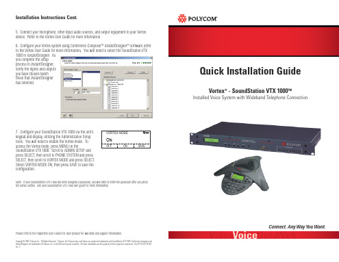
Option A: Connect the wall jack to the LINE connection on the rear of the Vortex device, then connect the PHONE jack on the Vortex device to the phone jack on the Interface Module. This will allow you to control the narrowband telephone capabilities of your Vortex device via a control system such as an AMX® or Crestron®, or with the keypad of the SoundStation VTX 1000.
2. Using the supplied color coded (white connector) cable, connect the desired output (such as Output B) of the Vortex Device (F) to the Auxiliary Input of the Interface Module (D).
- 1、下载文档前请自行甄别文档内容的完整性,平台不提供额外的编辑、内容补充、找答案等附加服务。
- 2、"仅部分预览"的文档,不可在线预览部分如存在完整性等问题,可反馈申请退款(可完整预览的文档不适用该条件!)。
- 3、如文档侵犯您的权益,请联系客服反馈,我们会尽快为您处理(人工客服工作时间:9:00-18:30)。
目录
目录 (1)
Linux 的安装 (2)
VTL软件安装 (15)
Linux 的安装
1.将Linux CD1 放入VTL机器的光驱,重启并选择光驱启动
2.回车继续
3.选择Skip,跳过光盘检查。
4.选择next进入下一页
5.选择下一步进入下一页
6.选择下一步进入下一页
7. 选择Custom, 并点击next进入下一页
8.选择Manually partition with Disk Druid,进行手动分区
9.选择Yes 确认手动分区会将现在磁盘数据进行破坏
10.创建最小三个分区
i. /boot 分区,建议容量>=100MB
ii. / 根分区,建议容量>=10GB
iii. Swap 交换分区,建议容量>=1.7GB
11. 选择Next进入下一页
12,按照当前环境,设置用户名,网络地址及掩码等
12. 取消防火墙设定
13.选择proceed进入下一页
14.点击下一步
15.输入管理员密码并进入下一页
16.选择上述模块
注:并在System tools这组包中增加选择sysstat 软件包
17.选择Next
18. 确认开始安装,直至结束。
19.选择reboot重启,操作系统安装完毕
VTL软件安装
1.将VTLCD放入光盘
2.Mount VTL CD
3.执行VTL安装命令
4.确认并续安装
5.确认每个SCSI ID后最多可以加载多少个LUN, 最大值为255
6.确定加载的设备及在操作系统创建设备文件的个数
7.确认做为VTL Target 的光纤卡的类型
8.确认是否配置
9.确认开始安装VTL软件
10.完成安装后,请确认重启
11.重启动完成后,可通过以下命令对VTL服务时行管理
a)#vtl status 看VTL的运行状态
b)#vtl start 启动VTL进程
c)#vtl stop 停止VTL进程。
