RCWP5100KKMWB中文资料
埃森平台 MW 系列微型电路保护器说明书

Protective Devices Miniature Circuit Breakers PLN4Catalog1.11EATON CORPORATION CA019074ENProtective DevicesMiniature Circuit Breakers PLN4 (MW)• T op-quality miniature circuit breakers 1P+N with a width of 1 module unit requiring little space for installation• Contact position indicator red - green • Guide for secure terminal connection • C omprehensive range of accessories can be mounted subsequently • Rated currents up to 40 A • Tripping characteristics B, C• R ated breaking capacity 4.5 kA according to IEC/EN 60898-1DescriptionSG157112EATON CORPORATION CA019074EN 3EATON CORPORATION CA019074ENSpecifications | Miniature Circuit Breakers PLN6, PLN4Description• High selectivity between MCB and back-up fuse due to low let-through energy • B usbar positioning optionally above or below • Compatible with standard busbar• Switching toggle in colour designating the rated current • M eets the requirements of insulation co-ordination, distance between con-tacts ³ 4 mm, for secure isolation • 1-pole breaking capacityI cn 1 = 3 kA Accessories:Auxiliary switch for subsequent installation ZP-IHK 286052ZP-WHK 286053Tripping signal switch for subsequent installation ZP-NHK 248437Remote control and automatic switching device Z-FW/LP 248296Shunt trip release ZP-ASA/..248438, 248439Undervoltage releaseZ-USA/..248288-248291Busbars:see capter busbar systemsTechnical DataPLN6, PLN4ElectricalDesign according toCurrent test marks as printed onto the device IEC/EN 60898-1Rated voltage U n 230 VAC Rated frequency50/60 Hz Rated breaking capacity according to IEC/EN 60898-1I cnPLN6 6 kA PLN4 4.5 kA Characteristic B, CBack-up fuse>6 kA max. 100 A gL/gG >4.5 kA max. 80 A gL/gG Selectivity class3Endurance electrical components ³ 8,000 switching operationsMechanical Frame size 45 mm Device height 80 mmDevice width 17.5 mm (1MU for 1+N)Mountingquick fastening with 2 lock-in positions on DIN rail IEC/EN 60715Degree of protectionIP20Upper and lower terminals open-mouthed/lift terminalsTerminal protection finger and hand touch safe, DGUV VS3, EN 50274Terminal capacity1-16 mm 2Connection diagram1+N-poleDimensions (mm)Rated current I n (A)TypeDesignationArticle No.Units per package4.5 kA, Characteristic BSG157116PLN4-B6/1N 26317912/12010PLN4-B10/1N 26318012/12013PLN4-B13/1N 26318112/12016PLN4-B16/1N 26318212/12020PLN4-B20/1N 26318312/12025PLN4-B25/1N 26318412/12032PLN4-B32/1N 26318512/12040PLN4-B40/1N26318612/1201+N-pole4.5 kA, Characteristic CSG157116PLN4-C6/1N 26318912/12010PLN4-C10/1N 26319012/12013PLN4-C13/1N 26319112/12016PLN4-C16/1N 26319212/12020PLN4-C20/1N 26319312/12025PLN4-C25/1N 26319412/12032PLN4-C32/1N 26319512/12040PLN4-C40/1N26319612/1201+N-pole Explanation PLN4:P = xPole , LN = Miniature Circuit Breakers 1P+N, 1MU , 4 = 4.5 kA4EATON CORPORATION CA019074EN5EATON CORPORATION CA019074ENShort-circuit Selectivity PLN4In case of short-circuit, there is selectivity between the miniature circuit breakers PLN4 and the upstream fuses up to the specified values of the selectivity limit current I s [kA] (i. e. in case of short-circuit currents I ks under I s only the MCB will trip, in case of short-circuit currents above this value both protective devices will respond).*) basically in accordance with EN 60898-1 D.5.2.bShort-circuit selectivity Characteristic B towards fuse link DII-DIV *)Short-circuit selectivity Characteristic C towards fuse link DII-DIV *)PLN4DII-DIV gL/gG I n [A]20253550638010060.7 1.2 2.9 4.52) 4.52) 4.52) 4.52)100.60.9 1.9 3.1 4.52) 4.52) 4.52)130.50.7 1.5 2.5 4.52) 4.52) 4.52)160.50.7 1.4 2.3 4.3 4.52) 4.52)200.50.7 1.4 2.2 4.0 4.52) 4.52)250.50.6 1.3 2.0 3.8 4.52) 4.52)320.50.6 1.2 1.8 3.4 4.52) 4.52)40<0.51)0.61.1 1.7 3.1 4.52) 4.52)Short-circuit selectivity Characteristic B towards fuse link D01-D03*)Short-circuit selectivity Characteristic C towards fuse link D01-D03*)PLN4DII-DIV gL/gG I n [A]2025355063801002 1.5 3.8 4.52) 4.52) 4.52) 4.52) 4.52)40.7 1.2 3.3 4.52) 4.52) 4.52) 4.52)60.7 1.1 2.6 4.52) 4.52) 4.52) 4.52)100.50.8 1.7 2.8 4.52) 4.52) 4.52)130.50.7 1.5 2.5 4.52) 4.52) 4.52)160.50.6 1.2 2.0 3.6 4.52) 4.52)200.50.61.2 1.8 3.3 4.52) 4.52)25<0.51)0.6 1.1 1.7 3.0 4.52) 4.52)32<0.51)0.6 1.0 1.6 2.8 4.52) 4.52)40<0.51)0.6 1.0 1.5 2.6 4.0 4.52)PLN4D01-D03 gL/gG I n [A]20253550638010060.60.9 2.5 4.52) 4.52) 4.52) 4.52)100.50.8 1.6 3.4 4.52) 4.52) 4.52)130.50.7 1.3 2.7 4.0 4.52) 4.52)160.50.6 1.3 2.5 3.8 4.52) 4.52)20<0.51)0.61.32.43.64.52) 4.52)25<0.51)0.6 1.2 2.3 3.3 4.52) 4.52)32<0.51)0.6 1.1 2.1 3.0 4.52) 4.52)40<0.51)0.6 1.0 2.0 2.8 4.52) 4.52)PLN4D01-D03 gL/gG I n [A]2025355063801002 1.1 2.0 4.52) 4.52) 4.52) 4.52) 4.52)40.60.9 2.7 4.52) 4.52) 4.52) 4.52)60.60.9 2.3 4.52) 4.52) 4.52) 4.52)100.50.7 1.5 3.0 4.52) 4.52) 4.52)130.50.71.32.7 4.0 4.52) 4.52)16<0.51)0.6 1.1 2.23.14.52) 4.52)20<0.51)0.6 1.1 2.1 2.9 4.52) 4.52)25<0.51)0.5 1.0 2.0 2.7 4.52) 4.52)32<0.51)0.5 1.0 1.9 2.6 4.52) 4.52)40<0.51)0.50.9 1.7 2.3 4.0 4.52)1) Selectivity limit current I sunder 0.5 kA2) S electivity limit current I s = rated breaking capacity I cn of the MCBShort-circuit selectivity Characteristic B towards fuse link NH-00*)Short-circuit selectivity Characteristic C towards fuse link NH-00*)PLN4NH-00 gL/gG I n [A]202532354050638010060.50.91.52.33.24.52) 4.52) 4.52) 4.52)10<0.51)0.7 1.2 1.5 2.0 3.1 3.9 4.52) 4.52)13<0.51)0.6 1.0 1.3 1.7 2.5 3.1 4.52) 4.52)16<0.51)0.6 1.0 1.3 1.6 2.4 2.9 4.52) 4.52)20<0.51)0.50.9 1.3 1.5 2.3 2.8 4.3 4.52)25<0.51)0.50.9 1.1 1.4 2.1 2.6 4.0 4.52)32<0.51)0.50.8 1.0 1.3 1.9 2.4 3.6 4.52)40<0.51)0.50.80.9 1.1 1.7 2.2 3.3 4.52)PLN4NH-00 gL/gG I n [A]202532354050638010020.7 2.1 4.52) 4.52) 4.52) 4.52) 4.52) 4.52) 4.52)40.50.9 1.6 2.6 3.7 4.52) 4.52) 4.52) 4.52)60.50.8 1.4 2.1 2.9 4.52) 4.52) 4.52) 4.52)10<0.51)0.6 1.0 1.4 1.9 2.8 3.5 4.52) 4.52)13<0.51)0.60.9 1.3 1.7 2.5 3.1 4.52) 4.52)16<0.51)0.50.7 1.0 1.3 2.0 2.5 3.8 4.52)20<0.51)0.50.70.9 1.2 1.8 2.3 3.5 4.52)25<0.51)0.50.70.9 1.1 1.6 2.1 3.3 4.52)32<0.51)<0.51)0.60.8 1.1 1.5 2.0 3.1 4.52)40<0.51)<0.51)0.60.8 1.0 1.4 1.9 2.9 4.52)Load Capacity PLN4Let-through Energy PLN4Determined according to 60898-1.Maximum let-through energy PLN4, Characteristic BMaximum let-through energy PLN4, Characteristic CLoad capacity in case of MCB block installationCurrent carrying capacity at ambient temperature (I n = 2-13 A)Permitted permanent load at ambient temperature T (°C) with n devices: I DL = I n K T (T)K N (N).Current carrying capacity at ambient temperature (I n = 16-25 A)Current carrying capacity at ambient temperature (I n = 32, 40 A)Number of devices (n)L o a d c a p a c i t y f a c t o r K N500300500100015002000300040005000600070001000015000800090004009007008006001500100030002000500040002000090007000100008000600015000300005000060000400007000080000prospektiver Kurzschlußstrom [A]D u r c h l a ße n e r g i e I t [A s e c ]22prospektiver Kurzschlußstrom [A]D u r c h l a ße n e r g i e I t [A s e c ]22500300500100015002000300040005000600070001000015000800090004009007008006001500100030002000500040002000090007000100008000600015000300005000060000400007000080000Prospective short-circuit current [A]L e t t h r o u g h e n e r g y I 2t [A 2 s e c ]Prospective short-circuit current [A]L e t t h r o u g h e n e r g y I 2t [A2 s e c ]EatonEMEA Headquarters Route de la Longeraie 71110 Morges, Switzerland Eaton.eu© 2020 EatonAll Rights Reserved Printed in AustriaPublication No. CA019074EN Article number 302799-MK July 2023Grafics: SRA, Schrems9010238178694Eaton Industries (Austria) GmbH Scheydgasse 421210 Vienna AustriaFollow us on social media to get the latest product and support information.Eaton is a registered trademark.All other trademarks are property of their respective owners.To contact us please visit https:///contacts For technical questions please contact your local Eaton team.Changes to the products, to the information contained in thisdocument, and to prices are reserved; as are errors and omissions.Only order confirmations and technical documentation by Eaton is binding. Photos and pictures also do not warrant a specific layout or functionality. Their use in whatever form is subject to prior approval by Eaton. The same applies to trademarks (especially Eaton, Moeller,and Cutler-Hammer). The Terms and Conditions of Eaton apply, as referenced on Eaton Internet pages and Eaton order confirmations.Eaton is an intelligent power management company dedicated toimproving the quality of life and protecting the environment for people everywhere. We are guided by our commitment to do business right, to operate sustainably and to help our customers manage power - today and well into the future. By capitalizing on the global growth trends of electrification and digitalization, we’re accelerating the planet’s transition to renewable energy, helping to solve the world’s most urgent power management challenges, and doing what’s best for our stakeholders and all of society.For more information, visit .。
RC0R5DB1K00JET;RW2S0CBR020JT;RW2R0DAR020JT;RW1S5CAR040J;RW3R5EAR050J;中文规格书,Datasheet资料
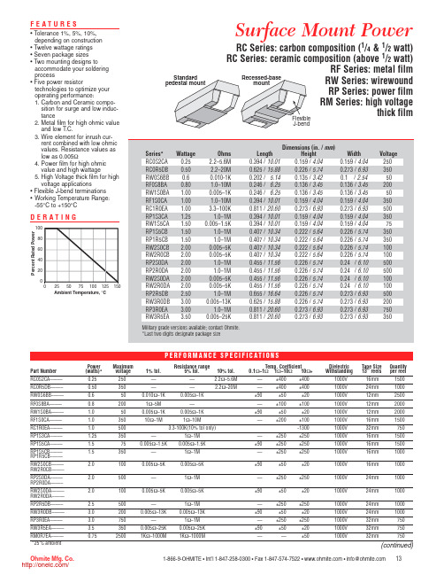
Width 0.159 / 4.04 0.273 / 6.93 0.1 / 2.54 0.136 / 3.45 0.136 / 3.45 0.159 / 4.04 0.273 / 6.93 0.159 / 4.04 0.159 / 4.04 0.226 / 5.74 0.226 / 5.74 0.226 / 5.74 0.226 / 5.74 0.24 / 6.10 0.24 / 6.10 0.24 / 6.10 0.24 / 6.10 0.273 / 6.93 0.273 / 6.93 0.273 / 6.93 0.273 / 6.93
Features
• Tolerance 1%, 5%, 10%, depending on construction • Twelve wattage ratings • Seven package sizes • Two mounting designs to accommodate your soldering process • Five power resistor technologies to optimize your operating performance: 1. Carbon and Ceramic composition for surge and low inductance 2. Metal film for high ohmic value and low T.C. 3. Wire element for inrush current combined with low ohmic values. Resistance values as low as 0.005Ω 4. Power film for high ohmic value and high wattage 5. High Voltage thick film for high voltage applications • Flexible J-bend terminations • Working Temperature Range: -55°C to +150°C
帕顿530以太网防雷器说明书.pdf
3
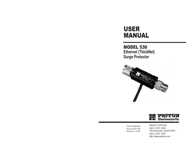
Using a hybrid circuit that incorporates Silicon Avalanche Diodes, the Model 530 can take repeated "hits" up to its rated capacity without degrading in performance. If the Model 530 should encounter a severe transient above its voltage rating, it will fail "open" to protect the connected hardware from damage. In this case, all signals (including data) are sent directly to ground, indicating to you that the Model 530 has "sacrificed itself" for your system and needs to be replaced.
• Operates at data rates to 10 Mbps
• Provides separate connection to chassis ground for surge handling
• Easy to install
DESCRIPTION
The Patton Model 530 thick Ethernet surge protector guards N-type Ethernet ports and connected equipment against data loss and hardware damage due to transient surges. Providing 1.8 Kilowatts of clamping transient protection, the Model 530 is easy to install and won't slow network performance.
MICOM-P520-电动机保护资料
!"#$%&'"#$()
!(
)
:90%
!"#$%&'
!"#$% !"#$% !"#$ !"#$ % !"
!"#$%& !"# !" !" !" #
!"#$%&'()*+,
!"#$%
!" äÉÖE
!"#$ I
F
1
!"#$
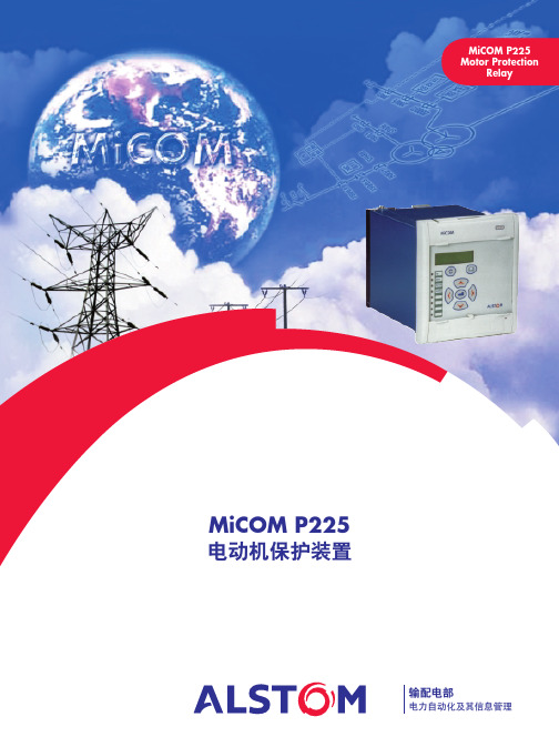
!"#$%&'( !"#$%&' MiCOM P225
!"#$%&'()*+,
2
!"#$
!"# 52 52+ !
!
1 0.1s 1 - 5 Iθ
!" Istart 0.5 Iθ 1s
CT
CT 1 - 3000A CT 1 - 3000A CT 1A 5A CT 1A 5A !"# CT 5P10-5VA !" CT CT !" CT !"#$%&'()*+ ! 1A 1A
! 0 - 100s !" /
!"#$%&'( )
4 MiCOM S10
!
!"#$%&'()*+, !"#$% !"
3 MiCOM S1 !" !"#$%&
!"#$
!"# !"# !
$%&'"() !"# !%&' !"#$% MiCOM
常用三极管参数大全

玉林万顺达电脑芯片级维修资料 2010-07-20整理玉林万顺达电脑芯片级维修资料 2010-07-20整理玉林万顺达电脑芯片级维修资料 2010-07-20整理玉林万顺达电脑芯片级维修资料 2010-07-20整理玉林万顺达电脑芯片级维修资料 2010-07-20整理玉林万顺达电脑芯片级维修资料 2010-07-20整理玉林万顺达电脑芯片级维修资料 2010-07-20整理玉林万顺达电脑芯片级维修资料 2010-07-20整理玉林万顺达电脑芯片级维修资料 2010-07-20整理玉林万顺达电脑芯片级维修资料 2010-07-20整理玉林万顺达电脑芯片级维修资料 2010-07-20整理玉林万顺达电脑芯片级维修资料 2010-07-20整理玉林万顺达电脑芯片级维修资料 2010-07-20整理玉林万顺达电脑芯片级维修资料 2010-07-20整理玉林万顺达电脑芯片级维修资料 2010-07-20整理玉林万顺达电脑芯片级维修资料 2010-07-20整理玉林万顺达电脑芯片级维修资料 2010-07-20整理玉林万顺达电脑芯片级维修资料 2010-07-20整理玉林万顺达电脑芯片级维修资料 2010-07-20整理玉林万顺达电脑芯片级维修资料 2010-07-20整理玉林万顺达电脑芯片级维修资料 2010-07-20整理玉林万顺达电脑芯片级维修资料 2010-07-20整理玉林万顺达电脑芯片级维修资料 2010-07-20整理玉林万顺达电脑芯片级维修资料 2010-07-20整理玉林万顺达电脑芯片级维修资料 2010-07-20整理玉林万顺达电脑芯片级维修资料 2010-07-20整理玉林万顺达电脑芯片级维修资料 2010-07-20整理玉林万顺达电脑芯片级维修资料 2010-07-20整理玉林万顺达电脑芯片级维修资料 2010-07-20整理玉林万顺达电脑芯片级维修资料 2010-07-20整理。
MGP W M 25 电机说明书
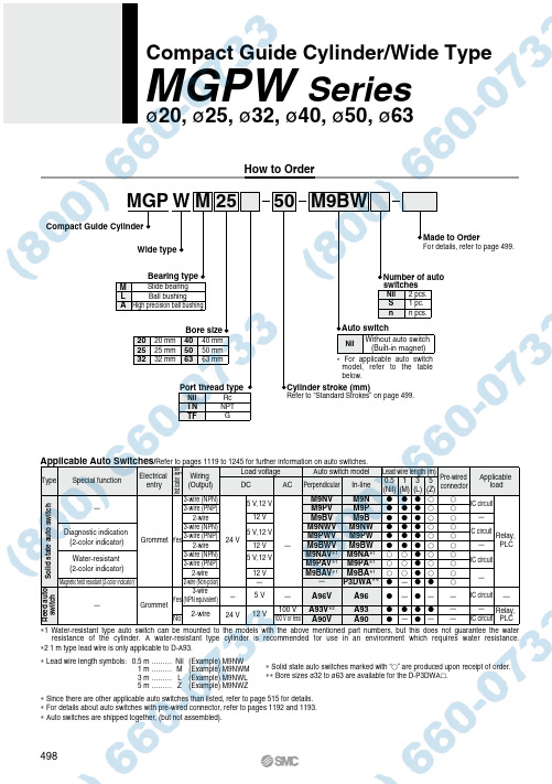
1.0 MPa
Minimum operating pressure
0.1 MPa
Ambient and fluid temperature
−10 to 60°C (No freezing)
Piston speed Note)
50 to 500 mm/s
Cushion
Rubber bumper on both ends
Lubrication Stroke length tolerance
Not required (Non-lube)
+1.5 0
mm
Note) Speed with no load
Standard Strokes
Bore size (mm) 20 to 63
Standard stroke (mm) 25, 50, 75, 100, 125, 150, 175, 200
—
Reed auto switch
—
3-wire Grommet Yes (NPN equivalent)
No 2-wire
— 24 V
5V
—
A96V
12 V
100 V 100 V or less
A93V∗2 A90V
A96
A93 A90
——
——
— IC circuit —
—
— Relay,
Applicable load
Solid state auto switch
—
3-wire (NPN) 3-wire (PNP)
5 V,12 V
M9NV M9PV
M9N M9P
IC circuit
2-wire
12 V
KWFB无密封自控自吸泵服务
故障现象
可能产生的原因
排除方法
4. 电 机 发 热
a.流量过大、超载运行。 b.碰擦。 c.电机轴承损坏。 d.电压不足。
a.关小出口阀。 b.检查排除。 c.更换轴承。 d.稳压。
5. 水 泵 漏 水
a.密封面不平整。 b.密封面螺栓松动。 c.出口止回阀损坏,停泵 时,副叶轮处漏水。
a.修整。 b.紧固。 c.修理或更换出口止 回阀
空气控制阀切断虹吸过程
KWFB产品特点
5. 特殊结构的导叶设计, 有4到5个出口,大大 增强了抽气能力,自 吸性能显著提高,较 采用单蜗壳式压水室 的泵型自吸时间缩短 1/3 ~ 1/2 以 上 。 增 强 了抽气能力,自吸性 能显著提高。
6. 优化设计的水力模型,采 用闭式叶轮,提高了水力 效率,降低了轴功率,具 有很明显的节能优势。
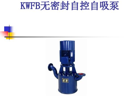
KWFB无密封自控自吸泵
KWFB产品应用场合
KWFB系列无密封自控自吸泵, 是我公司在 反复研究国内外同类产品的基础上,开发 成功的新产品。
该产品具有耐温、耐压、耐磨,“一次引 流,终身自吸”等多种功能与优点。在一 定条件下替代长轴泵、液下泵、潜水潜污 泵等设备。在石油、电力、化工、钢铁、 医药、焦化、电镀、环保、消防、市政、 净水、国防军工、纺织印染、采掘选矿、 民用建筑等行业中广泛应用,深受用户的 好评。
KWFB产品特点
1.采 用 优 化 设 计 的 “ 泵 用 连 环式多面离心动力密封装 置” ,革除了传统水泵的填 料密封、机械密封,彻底制 服了“跑、冒、滴、漏”。
2.可 靠 性 高 , 运 行中密封装置不 摩擦,使用寿命 较 同 类 产 品 长 10 倍以上,可靠性 高。增加了停机 密封装置,更加 适用于频繁起动 场合。
MP502W资料
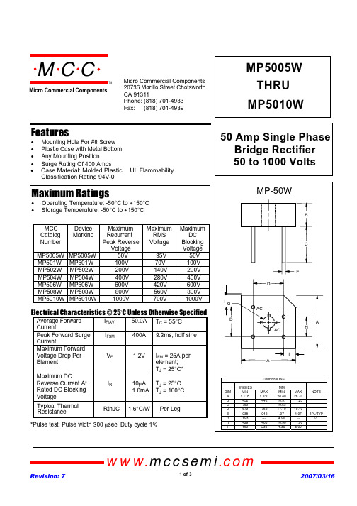
MP5005WTHRU MP5010W50 Amp Single Phase Bridge Rectifier 50 to 1000 VoltsFeaturesMaximum Ratings• Operating Temperature: -50°C to +150°C •Storage Temperature: -50°C to +150°C MCC Catalog NumberDevice MarkingMaximum Recurrent Peak Reverse VoltageMaximum RMS Voltage Maximum DC Blocking Voltage MP5005W MP5005W 50V 35V 50V MP501W MP501W 100V 70V 100V MP502W MP502W 200V 140V 200V MP504W MP504W 400V 280V 400V MP506W MP506W 600V 420V 600V MP508W MP508W 800V 560V 800V MP5010W MP5010W 1000V 700V1000VElectrical Characteristics @ 25°C Unless Otherwise SpecifiedAverage Forward CurrentI F(AV)50.0A T C = 55°C Peak Forward Surge CurrentI FSM 400A 8.3ms, half sine Maximum Forward Voltage Drop Per ElementV F1.2VI FM = 25A per element;T J = 25°C*Maximum DCReverse Current At Rated DC Blocking VoltageI R10µA 1.0mA T J = 25°C T J = 100°C *Pulse test: Pulse width 300 µsec, Duty cycle 1%• Mounting Hole For #8 Screw • Plastic Case with Metal Bottom • Any Mounting Position• Surge Rating Of 400 Ampsomp onents 20736 Marilla Street Chatsworth! "# $ % ! "#Micro Commercial ComponentsTypical Thermal ResistanceRthJC1.6°C/WxCase Material: Molded Plastic. UL Flammability Classification Rating 94V-0www.mccsemi .comPer LegMP5005W thru MP5010WFigure 1Typical Forward Characteristics AmpsFigure 2Typical Reverse CharacteristicsPeak Forward Surge Current - Amperes versus Number Of Cycles At 60Hz - CyclesCyclesAverage Forward Rectified Current - Amperes versus Case Temperature - °C102030Amps°C405060TMMicro Commercial Components www.mccsemi .comMicro Commercial Components***IMPORTANT NOTICE***Micro Commercial Components Corp.reserve s the right to make changes without further notice to any product herein to make corrections, modifications , enhancements , improvements , or other changes .Micro Commercial Components Corp.does not assume any liability arising out of the application or use of any product described herein; neither does it convey any license under its patent rights ,northe rights of others . The user of products in such applications shall assume all risks of such use and will agree to hold Micro Commercial Components Corp.and all the companies whoseproducts are represented on our website, harmless against all damages.***APPLICATIONS DISCLAIMER***Products offer by Micro Commercial Components Corp.are not intended for use in Medical,Aerospace or Military Applications.。
2050培训讲义

电台编程
• • 选择信道 信道编程
编程功能
2050电台有三种编程方式:• 用2050编程软件通过计算机编程,可以通过电台的辅助插口或前面板的红外端口传输信息; • 直接用前面板的键盘编程;
注意:- 这个功能可以由网络管理员在计算机编程时禁用。
• 用克隆电缆通过电台的辅助插口复制信息到另一个电台。
注意:- 如果需要,网络管理员可以在PC编程时禁用保护菜单和通用菜单。
保护菜单
常规设置 (General) 设置手咪上/下行键 (Mic Up/Down Keys)
手咪顶部的按键可以设置两种功能:选择信道和控制音量。也可以设置为禁用。
用翻页键选择需要的功能,然后按
键确认:
:
常规设置 “发送完毕”提示音 (Tx Over Beep)
8.
9.
CW电键输入
扬声器输出
10. 机壳接地
用户控制 - 2050 键盘
呼叫键 信道上行键 通用翻页键
音量增加 通用翻页键
信道下行键 通用翻页键
音量降低 通用翻页键
电源开/关
确认键
紧急呼叫键
向左翻页 数字键 1 向下翻页 ‘jkl ‟ 和 ‘5’ 进入调谐 接收方式 ‘ghi ‟ 和‘4’ 方式选择
天线类型 (Antenna Type)
I/O设置
选择所连接天线的类型,可以 以下5种选择:
Base Station( 基站) 使用宽带天线时选择此项。 910 Mobile antenna(910车载天线) 使用2019或910车载鞭天线时选择此项。 911 Automatic Tuner(911自动天调) 使用911自动天调或其它自动天调时选择此项。 Linear amplifier(线性放大器)
RCWP5100KZMWB中文资料
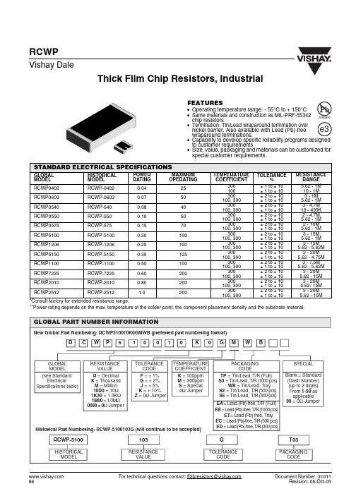
Thick Film Chip Resistors, Industrial For technical questions contact: ff2bresistors@Document Number: 31011RCWPVishay DaleFEATURES•Operating temperature range: - 55°C to + 150°C•Same materials and construction as MIL-PRF-55342chip resistors•Termination: Tin/Lead wraparound termination overnickel barrier. Also available with Lead (Pb)-freewraparound terminations.•to customer requirements•Size, value, packaging and materials can be customized for special customer requirements.*Consult factory for extended resistance range.**Power rating depends on the max. temperature at the solder point, the component placement density and the substrate material.STANDARD ELECTRICAL SPECIFICATIONSGLOBAL MODEL HISTORICAL MODEL POWER RATING MAXIMUM OPERATINGTEMPERATURE COEFFICIENTTOLERANCE%RESISTANCE RANGE RCWP0402RCWP-04020.0425300100± 1 to ± 10± 1 to ± 10 5.62 - 1M 10 - 1M RCWP0603RCWP-06030.0750300100, 300± 2 to ± 10± 1 to ± 10 3 - 1M 5.62 - 1M RCWP0540RCWP-5400.0840300100, 300± 2 to ± 10± 1 to ± 10 3 - 4.7M 10 - 499K RCWP0550RCWP-5500.1050300100, 300± 2 to ± 10± 1 to ± 10 2 - 4.7M 5.62 - 1M RCWP0575RCWP-5750.1570300100, 300± 2 to ± 10± 1 to ± 10 2 - 10M 5.62 - 1M RCWP5100RCWP-51000.20100300100, 300± 2 to ± 10± 1 to ± 10 3 - 15M 5.62 - 1M RCWP1206RCWP-12060.25100300100, 300± 2 to ± 10± 1 to ± 10 3 - 15M 5.62 - 5.62M RCWP5150RCWP-51500.35125300100, 300± 2 to ± 10± 1 to ± 10 3 - 20M 5.62 - 4.75M RCWP1100RCWP-11000.50100300100, 300± 2 to ± 10± 1 to ± 10 3 - 7.5M 5.62 - 5.62M RCWP7225RCWP-72250.60200300100, 300± 2 to ± 10± 1 to ± 10 3 - 20M 5.62 - 15M RCWP2010RCWP-20100.80200300100, 300± 2 to ± 10± 1 to ± 10 3 - 20M 5.62- 15M RCWP2512RCWP-25121.0200300100, 300± 2 to ± 10± 1 to ± 105 - 20M 5.62 - 15MRCWPThick Film Chip Resistors, IndustrialVishay DaleDocument Number: 31011For technical questions contact: ff2bresistors@DIMENSIONSDIMENSIONS [in millimeters]GLOBAL MODEL A (Len g th)B (Width)C (Hei g ht)D(Top Term)E(Bottom Term)RCWP04020.039 ± 0.003[0.99 ± 0.08]0.020 ± 0.003[0.51 ± 0.08]0.013 ± 0.003[0.33 ± 0.08]0.010 ± 0.005[0.25 ± 0.13]0.010 ± 0.005[0.25 ± 0.13]RCWP05400.055 ± 0.005[1.40 ± 0.13]0.040 ± 0.005[1.02 ± 0.13]0.020 ± 0.005[0.51 ± 0.13]0.010 ± 0.005[0.25 ± 0.13]0.010 ± 0.005[0.25 ± 0.13]RCWP05500.055 ± 0.005[1.40 ± 0.13]0.050 ± 0.005[1.27 ± 0.13]0.020 ± 0.005[0.51 ± 0.13]0.010 ± 0.005[0.25 ± 0.13]0.015 ± 0.005[0.38 ± 0.13]RCWP05750.080 ± 0.005[2.03 ± 0.13]0.050 ± 0.005[1.27 ± 0.13]0.020 ± 0.005[0.51 ± 0.13]0.015 ± 0.005[0.38 ± 0.13]0.015 ± 0.005[0.38 ± 0.13]RCWP06030.063 ± 0.005[1.60 ± 0.13]0.032 ± 0.005[0.81 ± 0.13]0.018 ± 0.005[0.46 ± 0.13]0.012 ± 0.005[0.31 ± 0.13]0.015 ± 0.005[0.38 ± 0.13]RCWP11000.105 ± 0.005[2.67 ± 0.13]0.100 ± 0.005[2.54 ± 0.13]0.020 ± 0.005[0.51 ± 0.13]0.015 ± 0.005[0.38 ± 0.13]0.015 ± 0.005[0.38 ± 0.13]RCWP12060.125 ± 0.005[3.18 ± 0.13]0.063 ± 0.005[1.60 ± 0.13]0.020 ± 0.005[0.51 ± 0.13]0.015 ± 0.005[0.38 ± 0.13]0.015 ± 0.005[0.38 ± 0.13]RCWP20100.197 ± 0.006[5.00 ± 0.15]0.098 ± 0.005[2.49 ± 0.13]0.020 ± 0.005[0.51 ± 0.13]0.020 ± 0.005[0.51 ± 0.13]0.020 ± 0.005[0.51 ± 0.13]RCWP25120.250 ± 0.006[6.35 ± 0.15]0.124 ± 0.005[3.15 ± 0.13]0.020 ± 0.005[0.51 ± 0.13]0.020 ± 0.005[0.51 ± 0.13]0.020 ± 0.005[0.51 ± 0.13]RCWP51000.105 ± 0.005[02.67 ± 0.13]0.050 ± 0.005[1.27 ± 0.13]0.020 ± 0.005[0.51 ± 0.13]0.015 ± 0.005[0.38 ± 0.13]0.015 ± 0.005[0.38 ± 0.13]RCWP51500.155 ± 0.005[3.94 ± 0.13]0.050 ± 0.005[1.27 ± 0.13]0.020 ± 0.005[0.51 ± 0.13]0.015 ± 0.005[0.38 ± 0.13]0.015 ± 0.005[0.38 ± 0.13]RCWP72250.230 ± 0.005[5.84 ± 0.13]0.075 ± 0.005[1.91 ± 0.13]0.020 ± 0.005[0.51 ± 0.13]0.020 ± 0.005[0.51 ± 0.13]0.020 ± 0.005[0.51 ± 0.13]Legal Disclaimer NoticeVishayNoticeSpecifications of the products displayed herein are subject to change without notice. Vishay Intertechnology, Inc., or anyone on its behalf, assumes no responsibility or liability for any errors or inaccuracies.Information contained herein is intended to provide a product description only. No license, express or implied, by estoppel or otherwise, to any intellectual property rights is granted by this document. Except as provided in Vishay's terms and conditions of sale for such products, Vishay assumes no liability whatsoever, and disclaims any express or implied warranty, relating to sale and/or use of Vishay products including liability or warranties relating to fitness for a particular purpose, merchantability, or infringement of any patent, copyright, or other intellectual property right. The products shown herein are not designed for use in medical, life-saving, or life-sustaining applications. Customers using or selling these products for use in such applications do so at their own risk and agree to fully indemnify Vishay for any damages resulting from such improper use or sale.。
IPAM-4050 数字量非隔离输入输出模块 用户手册
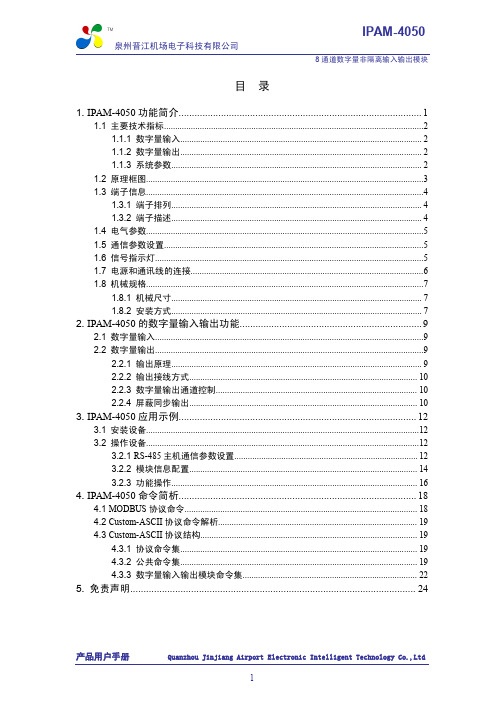
5. 免责声明............................................................................................................ 24
产品用户手册
Quanzhou Jinjiang Airport Electronic Intelligent Technology Co.,Ltd
4. IPAM-4050 命令简析.......................................................................................... 18
4.1 MODBUS 协议命令........................................................................................................ 18 4.2 Custom-ASCII 协议命令解析......................................................................................... 19 4.3 Custom-ASCII 协议结构................................................................................................. 19 4.3.1 协议命令集.......................................................................................................... 19 4.3.2 公共命令集.......................................................................................................... 19 4.3.3 数字量输入输出模块命令集.............................................................................. 22
VKM 系列中心力直径风机用户指南说明书

VKM 100 E VKM 100 VKM 125 E VKM 125 VKM 150 E VKM 150VKM 200 EVKM 200VKMS 200VKM 250 EVKM 250VKM 305 EVKM 305VKMS 305VKM 355 QVKM 400VKM 450 Centrifugal inline fansUSER’S MANUALVKM CONTENTSThis user’s manual is the primary operating document intended for technical, maintenance and operations staff.The user’s manual contains information regarding the field of application, delivery package, operating principle, and design of the VKM fan and all its modifications.Technical and maintenance staff must have proper theoretical knowledge and practical training specific to ventilation systems as well as the necessary skills to carry out the work in accordance with labour safety and construction regulations and standards applicable in the respective territory.The information provided in the present document is true as at the document preparation.Due to the continuous product development the company reserves the right to update the technical specifications, design or delivery package of its products.No part of the present publication may be reproduced, uploaded or saved in reference-providing information systems or translated into other languages in any form whatsoever without the company’s prior written consent.SAFETY REQUIREMENTS• Please read the user’s manual carefully prior to installing and operating the unit.• All user’s manual requirements as well as the provisions of all the applicable local and national construction, electrical, and technical norms and standards must be observed when installing and operating the unit.• The warnings contained in the user’s manual must be considered most seriously since they contain vital personal safety information.• Failure to follow the rules and safety precautions noted in this user’s manual may result in an injury or unit damage.• After a careful reading of the manual, keep it for the entire service life of the unit.• While transferring the unit control, the user’s manual must be turned over to the receiving operator.UNIT INSTALLATION AND OPERATION SAFETY PRECAUTIONS• Disconnect the unit from power mains priorto any installation operations.•Unpack the unit with care.• The unit must be grounded!• While installing the unit, follow the safety regulations specific to the use of electric tools.Safety requirements (2)Purpose (4)Delivery set (4)Designation key (4)Technical data (5)Design and operating principle (6)Installation and set-up (6)Connection to power mains (7)Technical maintenance (8)Possible malfunctions and troubleshooting (9)Storage and transportation regulations (9)Manufacturer’s warranty (10)Certificate of acceptance (11)Seller information (11)Installation certificate (11)Warranty card (11)• Do not change the power cable lengthat your own discretion. Do not bend the power cable. Avoid damaging the power cable. Do not put any foreign objects on thepower cable.• Do not lay the power cable of the unit in close proximity to heating equipment.• Do not use damaged equipment or cableswhen connecting the unit to power mains.• Do not operate the unit outside the temperature range stated in the user’s manual. Do not operate the unit inaggressive or explosive environments.• Do not touch the unit controls with wet hands. Do not carry out the installation and maintenance operations with wet hands.• Do not wash the unit with water. Protect the electric parts of the unit against ingress of water.• Do not allow children to operate the unit.• Disconnect the unit from power mains prior to any technical maintenance.• Do not store any explosive or highly flammable substances in close proximity to the unit.• When the unit generates unusual sounds, odour, or emits smoke, disconnect it from power supply and contact the Seller.• Do not open the unit during operation.• Do not direct the air flow produced by the unit towards open flame or ignition sources.• Do not block the air duct when the unit is switched on.• In case of continuous operation of the unit, periodically check the security of mounting.• Do not sit on the unit and avoid placingforeign objects on it.• Use the unit only for its intended purpose.VKMPURPOSEThe VENTS VKM centrifugal fans are designed for ventilation of domestic, public and manufacturing premises heated during winter.The transported air temperature must be within the limits stated in the «Technical data» section.The fan is designed for horizontal or vertical mounting in an air duct and is used both for supply and exhaust ventilation.Transported air must not contain any flammable or explosive mixtures, evaporation of chemicals, sticky substances, fibrous materials, coarse dust, soot and oil particles or environments favourable for the formation of hazardous substances (toxic substances, dust, pathogenic germs).NAMENUMBER Fan1 pc.Outer mounting bracket for VKM fans2 pcs.Outer mounting bracket for VKM E fans 1 er's manual 1 pc.Packing box1 pc.DESIGNATION KEYVKMSXXAdditional optionsE – equipped with an energy-saving motor Q - low powered motor Exhaust spigot diameter Increased capacity Fan seriesVKM – centrifugal inline fanDELIVERY SETTECHNICAL DATA Permitted deviation of mains voltage: ±10 % of the rated voltage. The fan must be grounded.* The parameters Volts, Watts, Amps are indicated at 0.2 in WG static pressureThe unit design is constantly being improved, thus some models, their wiring diagrams and terminal symbols may be slightly differentVKMDESIGN AND OPERATING PRINCIPLEINSTALLATION AND SET-UPThe fan consists of the casing 1, the electric motor attached to the inner fixing bracket 4, the cover 2 that is fixed to the casing with screws 3 (the casing spigot diameter and the cover diameter are equal to the connected air duct diameter), the terminal box 5 that incorporates a terminal block and a capacitor and enables connection of the fan to single-phase power mains.12345678 6 – outer fixing bracket 7 – screws 8 – boltFig. 1The fans are designed for vertical or horizontal mounting. Air motion in the system must be in compliance with the direction of the arrow on the fan casing. Install a hood on outlet (discharge) spigot side in case of the vertical fan installation. Provide a straight air duct sectionMounting sequence:• Remove the bolt from the casing 1 and install the fixing brackets in such a way so that the holes on the fixing brackets are aligned with the heads of the screws 3.• Fix the fixing brackets on the casing with bolts.• Drill the holes in the mounting surface to match the fitment holes of the fixing brackets.• Fix the fan with the screws.CONNECTION TO POWER MAINSThe fan is designed for 120 V / 60 Hz (for the VKM 100...305 fans ) or 230 V / 60 Hz (for the VKM 355Q, VKM 400, VKM 450 fans )single-phase alternating current mains.The fan shall be connected to power supply by means of insulated, durable and thermal-resistant cords (cables, wires) through the external circuit breaker with a thermal-magnetic trip built into the stationary wiring to disconnect all the power mains phases. The rated current must be not below the rated current consumption (refer to the «Technical data» section). The QF external switch location must ensure free access for quick shutdown of the fan.The recommended rated current of the circuit breaker:• 2 A for the VKM 355 Q fans• 3.15 A for the VKM 400, VKM 450 fans• 1 A for all other fansThe recommended wire cross section is minimum AWG 19.The actual conductor cross-section selection must be based on its type, maximum permissible heating, insulation, length and installation method (in the air, pipes or inside walls). Connect the cables to the terminal block incorporated inside the terminal box located on the fan casing in compliance with the fan wiring diagram and the terminal designation. The terminal designations are shown on the sticker inside the fan casing.The wiring diagram:~ 230 V60 HzFor the VKM 400, VKM 450 fans For the VKM 355 Q For the other fans The TW1, TW2 terminals are the electrical leads of the normally closed contact of the motor overheating protection.The QF circuit breaker is not included in the delivery and must be installed by the user.VKM TECHNICAL MAINTENANCEThe technical maintenance includes periodic cleaning of the surfaces from accumulated dust and dirt. Use a soft dry brush or a vacuum cleaner to remove dust.The impeller blades require thorough cleaning once in 6 months.To do this, unscrew the self-tapping screws 3 and remove the cover 2 (Fig. 1).Clean the impeller blades with a soft cloth wetted in mild water detergent solution. Avoid liquid dripping on the motor.PROBLEM POSSIBLE REASONS TROUBLESHOOTINGWhen switching on the unit the fan does not start.No power supply.Check the electrical connections and the power switch status. Motor jamming.Turn off the fan. Troubleshoot the impeller jamming. Restart thefan.Circuit breaker tripping during the fan start.The automatic circuit breaker istriggered by an abnormally high currentconsumption due to a short circuit.Disconnect the fan from power mains and contact the Seller.Do not turn on the fan again!Low air flow.Clogging of air ducts or other ventilationsystem elements. Impeller clogging.Damaged air ducts. Air damper closure.Clean the air ducts and other ventilation system elements aswell as the impeller. Check the air ducts for damage. Make surethe air dampers and louvre shutters are open.POSSIBLE MALFUNCTIONS AND TROUBLESHOOTINGSTORAGE AND TRANSPORTATION REGULATIONS• Store the unit in the manufacturer’s original packaging box in a dry closed ventilated premise with temperature range + 41...+104 ˚F and relative humidity up to 70 %.• Storage environment must not contain aggressive vapours and chemical mixtures provoking corrosion, insulation, and sealing deformation.• Use suitable hoist machinery for handling and storage operations to prevent possible damage to the unit.• Follow the handling requirements applicable for the particular type of cargo.• The unit can be carried in the original packaging by any mode of transport provided proper protection against precipitation and mechanical damage. The unit must be transported only in the working position.• Avoid sharp blows, scratches, or rough handling during loading and unloading.• Prior to the initial power-up after transportation at low temperatures allow the unit to warm up at room temperature for at least 3-4 hours.VKMMANUFACTURER’S WARRANTY Production meets standard operating requirements in the USA and Canada.VENTS warrants to the original purchaser of the unit that it will be free from defects in materials or workmanship for a period of 60 months from the date of original purchase. The VENTS warrants to the original purchaser of the unit that the integrated control unit will be free from defects in materials and workmanship for a period of 60 months from the date of original purchase.THERE ARE NO OTHER WARRANTIES, EXPRESS OR IMPLIED, INCLUDING, BUT NOT LIMITED TO,IMPLIED WARRANTIES OF MERCHANTABILITY OR FITNESS FOR A PARTICULAR PURPOSE.During the stated warranty period, VENTS will, at its option, repair or replace, without charge, any product or part which is found to be defective under normal use and service. This warranty does not cover (a) normal maintenance and normal service or (b) any products or parts which have been subject to misuse, negligence, accident, improper maintenance or repair (other than by VENTS), faulty installation or negligence, accident, improper maintenance or repair (other than by VENTS), faulty installation or installation contrary to recommended installation instructions. Labor to remove and replace products is not covered. The duration of any implied warranty is limited to the time period specified for the express warranty. Some states do not allow limitations on how long an implied warranty lasts, so the above limitation may not apply to you.VENTS US OBLIGATION TO REPAIR OR REPLACE, AT VENTS US OPTION, SHALL BE THE PURCHASER’S SOLE AND EXCLUSIVE REMEDY UNDER THIS WARRANTY. VENTS US SHALL NOT BE LIABLE FOR INCIDENTAL, CONSEQUENTIAL OR SPECIAL DAMAGES ARISING OUT OF OR IN CONNECTION WITH PRODUCT USE OR PERFORMANCE.Some states do not allow the exclusion or limitations of incidental or consequential damages, so the above limitation or exclusion may not apply to you. This warranty gives you specific legal rights, and you may also have other rights which vary from state to state. This warranty supersedes all prior warranties. If proof of sales date is absent, warranty period is calculated from the production date. The unit can be exchanged at the following address:Bodor Vents, LLC DBA: VENTS11013 Kenwood Road Cincinnati, Ohio 45242Phone: (513)348-3853e-mail:*****************Please follow guidelines in this manual for product problem-free operation. Unit TypeCentrifugal inline fan Seller’s Stamp ModelVKM______Serial NumberManufacture DatePurchase DateWarranty PeriodSellerSellerSeller’s StampAddressPhone NumberE-mailPurchase DateThis is to certify acceptance of the complete unit delivery with the user’s manual. The warranty terms are acknowledged and accepted.Customer’s Signature The VKM______ unit has been connected to power mains pursuant to the requirements stated in the present user’s manual.Installation Stamp SellerAddressPhone NumberInstallation Technician’s Full NameInstallation Date:Signature:The unit has been installed in accordance with the provisions of all the applicable local and national construction,electrical and technical codes and standards. The unit operates normally as intended by the manufacturer.Signature:Seller informationInstallation certificateWarranty cardVUSA05EN-08。
Makita WT01 无线电力扳手说明书

011762ENGLISH (Original instructions) SPECIFICATIONSModelWT01 Standard bolt M8 - M12 (5/16" - 1/2")CapacitiesHigh tensile bolt M6 - M10 (1/4" - 3/8")Square drive 9.5 mm (3/8")No load speed (RPM) 0 -2,300/min.Impacts per minute 0 - 3,000Max. fastening torque 110 N.m (1,000 in.lbs)Overall length 163 mm (6-3/8")Net weight 0.95 kg (2.1 lbs)Rated voltage D.C. 10.8V/12VmaxStandard battery cartridges BL1014• Due to our continuing programme of research and development, the specifications herein are subject to change without notice. • Specifications and battery cartridge may differ from country to country.• Weight, with battery cartridge, according to EPTA-Procedure 01/2003GEA006-2 General Power Tool SafetyWARNING Read all safety warnings and all instructions. Failure to follow the warnings and instructions may result in electric shock, fire and/or serious injury.Save all warnings and instructions for future reference. The term "power tool" in the warnings refers to your mains-operated (corded) power tool or battery-operated (cordless) power tool.Work area safety1. Keep work area clean and well lit. Cluttered ordark areas invite accidents.2. Do not operate power tools in explosiveatmospheres, such as in the presence offlammable liquids, gases or dust. Power toolscreate sparks which may ignite the dust or fumes.3. Keep children and bystanders away whileoperating a power tool. Distractions can causeyou to lose control.Electrical safety4. Power tool plugs must match the outlet. Nevermodify the plug in any way. Do not use anyadapter plugs with earthed (grounded) powertools. Unmodified plugs and matching outlets willreduce risk of electric shock.5. Avoid body contact with earthed or groundedsurfaces such as pipes, radiators, ranges andrefrigerators. There is an increased risk ofelectric shock if your body is earthed or grounded.6. Do not expose power tools to rain or wetconditions. Water entering a power tool willincrease the risk of electric shock.7. Do not abuse the cord. Never use the cord forcarrying, pulling or unplugging the power tool.Keep cord away from heat, oil, sharp edges ormoving parts. Damaged or entangled cordsincrease the risk of electric shock.8. When operating a power tool outdoors, use anextension cord suitable for outdoor use. Use ofa cord suitable for outdoor use reduces the risk ofelectric shock.9. If operating a power tool in a damp location isunavoidable, use a ground fault circuitinterrupter (GFCI) protected supply. Use of anGFCI reduces the risk of electric shock.Personal safety10. Stay alert, watch what you are doing and usecommon sense when operating a power tool.Do not use a power tool while you are tired orunder the influence of drugs, alcohol ormedication. A moment of inattention whileoperating power tools may result in seriouspersonal injury.e personal protective equipment. Alwayswear eye protection. Protective equipment suchas dust mask, non-skid safety shoes, hard hat, orhearing protection used for appropriate conditionswill reduce personal injuries.12. Prevent unintentional starting. Ensure theswitch is in the off-position before connectingto power source and/or battery pack, pickingup or carrying the tool. Carrying power tools withyour finger on the switch or energising power toolsthat have the switch on invites accidents.13. Remove any adjusting key or wrench beforeturning the power tool on. A wrench or a key leftattached to a rotating part of the power tool mayresult in personal injury.14. Do not overreach. Keep proper footing andbalance at all times. This enables better controlof the power tool in unexpected situations.15. Dress properly. Do not wear loose clothing orjewellery. Keep your hair, clothing, and glovesaway from moving parts. Loose clothes,jewellery or long hair can be caught in movingparts.16. If devices are provided for the connection ofdust extraction and collection facilities,ensure these are connected and properly used.Use of dust collection can reduce dust-relatedhazards.Power tool use and care17. Do not force the power tool. Use the correctpower tool for your application. The correctpower tool will do the job better and safer at therate for which it was designed.18. Do not use the power tool if the switch doesnot turn it on and off. Any power tool that cannotbe controlled with the switch is dangerous andmust be repaired.19. Disconnect the plug from the power sourceand/or the battery pack from the power toolbefore making any adjustments, changingaccessories, or storing power tools. Suchpreventive safety measures reduce the risk ofstarting the power tool accidentally.20. Store idle power tools out of the reach ofchildren and do not allow persons unfamiliarwith the power tool or these instructions tooperate the power tool. Power tools aredangerous in the hands of untrained users.21. Maintain power tools. Check for misalignmentor binding of moving parts, breakage of partsand any other condition that may affect thepower tool’s operation. If damaged, have thepower tool repaired before use. Many accidentsare caused by poorly maintained power tools. 22. Keep cutting tools sharp and clean. Properlymaintained cutting tools with sharp cutting edgesare less likely to bind and are easier to control. 23. Use the power tool, accessories and tool bitsetc. in accordance with these instructions,taking into account the working conditionsand the work to be performed. Use of the powertool for operations different from those intendedcould result in a hazardous situation.Battery tool use and care24. Recharge only with the charger specified bythe manufacturer. A charger that is suitable forone type of battery pack may create a risk of firewhen used with another battery pack.25. Use power tools only with specificallydesignated battery packs. Use of any otherbattery packs may create a risk of injury and fire.26. When battery pack is not in use, keep it awayfrom other metal objects, like paper clips,coins, keys, nails, screws or other small metalobjects, that can make a connection from oneterminal to another. Shorting the batteryterminals together may cause burns or a fire.27. Under abusive conditions, liquid may beejected from the battery; avoid contact. Ifcontact accidentally occurs, flush with water. Ifliquid contacts eyes, additionally seek medicalhelp. Liquid ejected from the battery may causeirritation or burns.Service28. Have your power tool serviced by a qualifiedrepair person using only identical replacementparts. This will ensure that the safety of the powertool is maintained.29. Follow instruction for lubricating andchanging accessories.30. Keep handles dry, clean and free from oil andgrease.GEB049-2 CORDLESS IMPACT WRENCH SAFETY WARNINGS1. Hold power tool by insulated grippingsurfaces, when performing an operation wherethe fastener may contact hidden wiring.Fasteners contacting a "live" wire may makeexposed metal parts of the power tool "live" andcould give the operator an electric shock.2. Wear ear protectors.3. Check the socket carefully for wear, cracks ordamage before installation.4. Hold the tool firmly.5. Always be sure you have a firm footing.Be sure no one is below when using the tool inhigh locations.6. The proper fastening torque may differdepending upon the kind or size of the bolt.Check the torque with a torque wrench.SAVE THESE INSTRUCTIONS.DO NOT let comfort or familiarity with product (gained from repeated use) replace strict adherence to safety rules for the subject product. MISUSE or failure to follow the safety rules stated in this instruction manual may cause serious personalinjury.USD302-1 SymbolsThe followings show the symbols used for tool.voltsdirect currentno load speedrevolutions or reciprocation per minutenumber of blowENC007-7 IMPORTANT SAFETY INSTRUCTIONSFOR BATTERY CARTRIDGE1. Before using battery cartridge, read allinstructions and cautionary markings on (1)battery charger, (2) battery, and (3) productusing battery.2. Do not disassemble battery cartridge.3. If operating time has become excessivelyshorter, stop operating immediately. It mayresult in a risk of overheating, possible burnsand even an explosion.4. If electrolyte gets into your eyes, rinse themout with clear water and seek medicalattention right away. It may result in loss ofyour eyesight.5. Do not short the battery cartridge:(1) Do not touch the terminals with anyconductive material.(2) Avoid storing battery cartridge in acontainer with other metal objects such asnails, coins, etc.(3) Do not expose battery cartridge to wateror rain.A battery short can cause a large current flow,overheating, possible burns and even a breakdown.6. Do not store the tool and battery cartridge inlocations where the temperature may reach orexceed 50 C (122F).7. Do not incinerate the battery cartridge even ifit is severely damaged or is completely wornout. The battery cartridge can explode in a fire.8. Be careful not to drop or strike battery.9. Do not use a damaged battery.SAVE THESE INSTRUCTIONS. Tips for maintaining maximum battery life1. Charge the battery cartridge before completelydischarged.Always stop tool operation and charge thebattery cartridge when you notice less toolpower.2. Never recharge a fully charged batterycartridge.Overcharging shortens the battery service life.3. Charge the battery cartridge with roomtemperature at 10 C - 40 C (50 F - 104F).Let a hot battery cartridge cool down beforecharging it.4. Charge the battery cartridge once in every sixmonths if you do not use it for a long period oftime.FUNCTIONAL DESCRIPTION• Always be sure that the tool is switched off and the battery cartridge is removed before adjusting or checking function on the tool.Installing or removing battery cartridge• Always switch off the tool before installing or removing of the battery cartridge.• To remove the battery cartridge, withdraw it from the tool while pressing the buttons on both sides ofthe cartridge.• To install the battery cartridge, hold it so that the battery cartridge front shape fits to that of thebattery installment opening and slip it into place.Always insert it all the way until it locks in place witha little click. If not, it may accidentally fall out of thetool, causing injury to you or someone around you. • Do not use force when installing the battery cartridge. If the cartridge does not slide in easily, itis not being inserted correctly.1. Button2. Battery cartridgeSwitch action1• Before inserting the battery cartridge into the tool, always check to see that the switch trigger actuatesproperly and returns to the "OFF" position whenreleased.To start the tool, simply pull the switch trigger. Tool speed is increased by increasing pressure on the switch trigger. Release the switch trigger to stop.Electric brakeThis tool is equipped with an electric brake. If the tool consistently fails to quickly stop after switch trigger release, have tool serviced at a Makita service center. Turning on the front lamp1• Do not look in the light or see the source of light directly.Pull the switch trigger to turn on the light. The lamp keeps on lighting while the switch trigger is being pulled. NOTE:• Use a dry cloth to wipe the dirt off the lens of lamp.Be careful not to scratch the lens of lamp, or it maylower the illumination.Reversing switch actionThis tool has a reversing switch to change the direction of rotation. Depress the reversing switch lever from the A side for clockwise rotation or from the B side for counterclockwise rotation.When the reversing switch lever is in the neutral position,the switch trigger cannot be pulled.• Always check the direction of rotation before operation.• Use the reversing switch only after the tool comes to a complete stop. Changing the direction of rotation before the tool stops may damage the tool. • When not operating the tool, always set the reversing switch lever to the neutral position.ASSEMBLY• Always be sure that the tool is switched off and the battery cartridge is removed before carrying outany work on the tool.Selecting correct socketAlways use the correct size socket for bolts and nuts. An incorrect size socket will result in inaccurate and inconsistent fastening torque and/or damage to the bolt or nut.Installing or removing socketTo install the socket, push it onto the anvil of the tool until it locks into place.To remove the socket, simply pull it off.1. Socket2. Anvil1. Reversingswitch lever1. Lamp1. Switch triggerOPERATIONThe proper fastening torque may differ depending upon the kind or size of the bolt, the material of the workpiece to be fastened, etc. The relation between fastening torque and fastening time is shown in the figures.Hold the tool firmly and place the socket over the bolt or nut. Turn the tool on and fasten for the proper fastening time.NOTE:•When fastening screw M8 (5/16") or smaller, carefully adjust pressure on the switch trigger so that the screw is not damaged.• Hold the tool pointed straight at the bolt or nutwithout applying excessive pressure on the tool. • Excessive fastening torque may damage thebolt/nut or socket. Before starting your job, alwaysperform a test operation to determine the properfastening time for your bolt or nut. Especially for thebolt smaller than M8 (5/16"), perform the above testoperation to prevent the trouble on socket or bolt,etc.• If the tool is operated continuously until the battery cartridge has discharged, allow the tool to rest formore than 15 minutes before proceeding with afresh battery.The fastening torque is affected by a wide variety of factors including the following. After fastening, always check the torque with a torque wrench.1.When the battery cartridge is discharged almostcompletely, voltage will drop and the fasteningtorque will be reduced.2.Socket• Failure to use the correct size socket will causea reduction in the fastening torque.• A worn socket (wear on the hex end or square end) will cause a reduction in the fasteningtorque.3.Bolt• Even though the torque coefficient and the class of bolt are the same, the proper fasteningtorque will differ according to the diameter ofbolt.• Even though the diameters of bolts are the same, the proper fastening torque will differaccording to the torque coefficient, the class ofbolt and the bolt length.4.The use of the universal joint or the extension barsomewhat reduces the fastening force of theimpact wrench. Compensate by fastening for alonger period of time.5.The manner of holding the tool or the material ofdriving position to be fastened will affect thetorque.6.Operating the tool at low speed will cause areduction in the fastening torque.Using holster (optional accessory)• Do not use for tools such as a drill with a bit installed on them.• Turn off a tool and wait until it comes to a complete stop before placing in the holster.Be sure to close the holster securely so that it holdsthe tool firmly.008807Thread a waist belt or similar through holster holder.008808Put the tool in the holster and lock it with the holster button.MAINTENANCE• Always be sure that the tool is switched off and the battery cartridge is removed before attempting toperform inspection or maintenance.• Never use gasoline, benzine, thinner, alcohol or the like. Discoloration, deformation or cracks mayresult.To maintain product SAFETY and RELIABILITY, repairs, any other maintenance or adjustment should be performed by Makita Authorized or Factory Service Centers, always using Makita replacement parts.OPTIONAL ACCESSORIES• These accessories or attachments are recommended for use with your Makita toolspecified in this manual. The use of any otheraccessories or attachments might present a risk ofinjury to persons. Only use accessory or attachment for its stated purpose.If you need any assistance for more details regarding these accessories, ask your local Makita Service Center. • Plastic carrying case• Various type of Makita genuine batteries and chargers• Holster NOTE:• Some items in the list may be included in the tool package as standard accessories. They may differ from country to country.。
戴尔 P513w 系列用户手册说明书

Dell P513w Series 用户手册2010年8月 | 机器类型:4443型号:目录安全信息 (5)关于您的打印机 (6)感谢您选择此打印机! (6)使您的打印机对环境的影响最小 (6)查找有关打印机的信息 (7)了解打印机的部件 (9)订购和更换耗材 (11)订购打印墨盒 (11)更换打印墨盒 (11)回收Dell产品 (13)使用打印机操作面板按钮和菜单 (14)使用打印机操作面板 (14)将临时设置改变为新的默认设置 (15)改变节约能源时限 (16)使用经济模式节约纸张和能源 (17)恢复出厂默认设置 (17)使用打印机软件 (18)最小系统需求 (18)使用Windows打印机软件 (18)使用Macintosh(英文版)打印机软件 (20)查找并安装可选的软件 (21)升级打印机软件(仅限于Windows) (21)重新安装打印机软件 (22)装入纸张和文档原件 (24)装入纸张 (24)保存纸张默认设置 (27)将文档原件放置在扫描仪玻璃上 (28)打印 (29)打印提示 (29)打印基本文档 (29)打印特殊文档 (33)操作照片 (35)在纸张的双面进行打印 (41)管理打印作业 (44)复印 (48)复印提示 (48)进行复印 (48)复印照片 (48)复印双面文档 (49)放大或缩小图像 (49)调整复印质量 (49)使复印结果较浅或者较深 (50)使用打印机操作面板进行逐份复印 (50)在一页纸上复制图像 (50)将多页文档复印到一张纸上 (51)进行双面复印 (51)取消复印作业 (52)扫描 (53)扫描提示 (53)扫描到本地或网络计算机 (53)扫描至闪存驱动器或存储卡 (54)扫描照片并发送到编辑应用程序中 (54)扫描文档并发送到编辑应用程序中 (55)使用打印机软件直接扫描至电子邮件 (56)扫描至PDF (56)扫描常见问答 (57)取消扫描作业 (58)网络 (59)在无线网络中安装打印机 (59)高级无线设置 (63)网络常见问答 (69)维护打印机 (80)维护打印墨盒 (80)清洗打印机的外壳 (82)擦洗扫描仪玻璃 (82)问题解答 (83)在您解决问题之前 (83)使用服务中心解决打印机问题 (83)如果问题解答没有解决您的问题 (83)安装问题解答 (83)卡纸和进纸错误问题解答 (89)打印问题解答 (92)复印和扫描问题解答 (94)存储卡问题解答 (96)无线问题解答 (97)通告 (115)产品信息 (115)版本通告 (115)能源消耗 (117)索引 (120)安全信息电源线所连接的电源插座与产品的距离不可太远,并且要符合使用方便的原则。
CW主机说明书中文资料
CW系列电涡流测功机主机使用说明书豫制03000011号凯迈 (洛阳) 机电有限公司(原洛阳南峰机电设备制造有限公司)目录1、引言 (4)1.1 概述 (4)1.2 电涡流测功机型号含义及技术参数 (5)2、电涡流测功机的主机结构和工作原理 (6)2.1电涡流测功机的工作原理 (6)2.2 电涡流测功机的功率计算 (6)2.3 电涡流测功机的主机结构 (6)2.4 电涡流测功机的报警装置 (7)3、电涡流测功机的主要技术指标 (8)4、电涡流测功机的布置和安装 (8)4.1 电涡流测功机的工作条件 (8)4.2 电涡流测功机的布置 (8)4.3 电涡流测功机的安装 (8)5、电涡流测功机测功机的冷却 (11)5.1.电涡流测功机的冷却原理 (11)5.2 电涡流测功机对冷却水水质的要求 (11)5.3 电涡流测功机冷却水水量的确定 (11)6、电涡流测功机的润滑 (12)6.1电涡流测功机的油润滑 (12)6.2电涡流测功机的脂润滑 (13)6.3电涡流测功机摆动轴承的润滑 (13)7、电涡流测功机的校准和调节 (14)7.1 电涡流测功机的静校 (14)7.2 电涡流测功机的灵敏度检查 (18)8、电涡流测功机的运输和维护 (18)8.1 电涡流测功机的贮存 (18)8.2 电涡流测功机的运输 (18)8.3 电涡流测功机的检查和维护 (19)9、电涡流测功机的配套 (19)10、电涡流测功机主机的常见故障和排除方法 (20)11、电涡流测功机新润滑系统的使用和维护 (21)12、电涡流测功机的图册部分 (22)图1(a)~(b)电涡流测功机的主机结构 (23)图2(a)~(o)电涡流测功机的机械特性曲线 (25)图3(a)~(m)电涡流测功机的外形尺寸 (40)图4(a)~(i)电涡流测功机的接线图 (53)图5 电涡流测功机进水温度、使用功率和水量之间的关系 (62)1、引言1.1 概述我公司根据德国策尔纳(ZÖLLNER)公司专有技术生产的CW系列电涡流测功机,具有低惯性、高精度、高稳定性和结构简单、维修方便、自成系列并适用于操作控制自动化等优点。
KKKAP风机的运行保护手册中英文对照
Operating and Maintenance Manualfor Fans Type KK&KKK&K风机的运行和保护手册Type: 类型:CKPF-Job-No.: 工作号:Machine-No.: 设备号:Application: 应用:Year of design: 设计年份:Client No.: 客户号Plant: 厂家:Plant Location: 厂家地址:Chengdu KK&K Power Fan Co. Ltd. 成都KK&K电站风机有限公司610041 Changyi Road 12 610041 长益路 12Wuhou District Chengdu City 成都市武侯区Sichuan Province 四川省Tel. +86…Fax +86…This instruction is exclusive property of Chengdu KK&K Power Fan Co. Ltd.Availability is limited to supervisors or service personnel. Surrender to or access by third persons, as well as duplication of the plant in its entirety or in parts is prohibited. We reserve the right to claim for full reimbursement of all damages resulting form non-compliance.We must point out that these operating instructions cannot always cover every eventuality completely. Accordingly they do not free the operator from the usual responsibility when operating technical equipment also in respects of health, safety and environmental protection. It is assumed that the operation personnel has been instructed and knows how to run the plant.No claims of any kind may be derived from these operating & maintenance instructions.该说明书版权为成都KK&K所有。
MW电源产品样本和技术资料中的术语解释
4. 减载曲线:电源在产品标准允许的工作温度、拔海高度范围、输入电压、安装方式(水平/垂直)规定条件以外应用时,反映其负载能力下降的函数关系。例如:工作温度超过40度后,输出功率将降低,即不能满功率应用。如果选型时未留功率余量,此刻将会触发过流或过载报警/保护。为防止该状况出现,用户需减载运行。
2. 交流突入电流:启动时的输入线中流过的浪涌电流。
3. 过载/过流/短路保护模式:有以下几种方式:1.重启(断开电源后再次接通,分自动和手动两种);2.打嗝(hiccup:间断式输出);3.Fold back limiting(在负载接近短路时,能线性地降低输出电流至正常值的方法);4.限流(Constant current lim恒流);5.宕机
ip是电源外壳防护等级的符号后面的数字越大防护等级越高详见国家标准ip67防护等级的电源可以在水深不超过1米的水中放置不超过30分钟可长期连续在湿度为100的环境下工作
MW电源产品样本和技术资料中的术语解释
1. 国际通用全范围输入:90(85)~295(305)Vac/127~431Vdc。或者180~480(528)Vac/254~679(747)Vdc输入电压范围。
5. PFC/双级/单级:PFC是功率因数校正,双级/单级是指PFC电路的数量。单级的功率因数最大不超过0.9,纹波较大。应用会受到某些限制(输入电源能力,将电路板用防水胶密封起来称为灌胶。此胶还有导热作用,可起到散热作用,以利于延长电源寿命。
10. Class 2电源:是指电源的绝缘通过加强措施,不需要通过机壳连接地线来提供防触电保护。供电只需用两线即可。
11. 泄漏电流:是指由电源外壳流入地线的电流。其中包含外壳的感应电流,和EMI电路中Y电容跨接于相线(火线)与地线所产生的电流。
- 1、下载文档前请自行甄别文档内容的完整性,平台不提供额外的编辑、内容补充、找答案等附加服务。
- 2、"仅部分预览"的文档,不可在线预览部分如存在完整性等问题,可反馈申请退款(可完整预览的文档不适用该条件!)。
- 3、如文档侵犯您的权益,请联系客服反馈,我们会尽快为您处理(人工客服工作时间:9:00-18:30)。
Thick Film Chip Resistors, Industrial For technical questions contact: ff2bresistors@Document Number: 31011RCWPVishay DaleFEATURES•Operating temperature range: - 55°C to + 150°C•Same materials and construction as MIL-PRF-55342chip resistors•Termination: Tin/Lead wraparound termination overnickel barrier. Also available with Lead (Pb)-freewraparound terminations.•to customer requirements•Size, value, packaging and materials can be customized for special customer requirements.*Consult factory for extended resistance range.**Power rating depends on the max. temperature at the solder point, the component placement density and the substrate material.STANDARD ELECTRICAL SPECIFICATIONSGLOBAL MODEL HISTORICAL MODEL POWER RATING MAXIMUM OPERATINGTEMPERATURE COEFFICIENTTOLERANCE%RESISTANCE RANGE RCWP0402RCWP-04020.0425300100± 1 to ± 10± 1 to ± 10 5.62 - 1M 10 - 1M RCWP0603RCWP-06030.0750300100, 300± 2 to ± 10± 1 to ± 10 3 - 1M 5.62 - 1M RCWP0540RCWP-5400.0840300100, 300± 2 to ± 10± 1 to ± 10 3 - 4.7M 10 - 499K RCWP0550RCWP-5500.1050300100, 300± 2 to ± 10± 1 to ± 10 2 - 4.7M 5.62 - 1M RCWP0575RCWP-5750.1570300100, 300± 2 to ± 10± 1 to ± 10 2 - 10M 5.62 - 1M RCWP5100RCWP-51000.20100300100, 300± 2 to ± 10± 1 to ± 10 3 - 15M 5.62 - 1M RCWP1206RCWP-12060.25100300100, 300± 2 to ± 10± 1 to ± 10 3 - 15M 5.62 - 5.62M RCWP5150RCWP-51500.35125300100, 300± 2 to ± 10± 1 to ± 10 3 - 20M 5.62 - 4.75M RCWP1100RCWP-11000.50100300100, 300± 2 to ± 10± 1 to ± 10 3 - 7.5M 5.62 - 5.62M RCWP7225RCWP-72250.60200300100, 300± 2 to ± 10± 1 to ± 10 3 - 20M 5.62 - 15M RCWP2010RCWP-20100.80200300100, 300± 2 to ± 10± 1 to ± 10 3 - 20M 5.62- 15M RCWP2512RCWP-25121.0200300100, 300± 2 to ± 10± 1 to ± 105 - 20M 5.62 - 15MRCWPThick Film Chip Resistors, IndustrialVishay DaleDocument Number: 31011For technical questions contact: ff2bresistors@DIMENSIONSDIMENSIONS [in millimeters]GLOBAL MODEL A (Len g th)B (Width)C (Hei g ht)D(Top Term)E(Bottom Term)RCWP04020.039 ± 0.003[0.99 ± 0.08]0.020 ± 0.003[0.51 ± 0.08]0.013 ± 0.003[0.33 ± 0.08]0.010 ± 0.005[0.25 ± 0.13]0.010 ± 0.005[0.25 ± 0.13]RCWP05400.055 ± 0.005[1.40 ± 0.13]0.040 ± 0.005[1.02 ± 0.13]0.020 ± 0.005[0.51 ± 0.13]0.010 ± 0.005[0.25 ± 0.13]0.010 ± 0.005[0.25 ± 0.13]RCWP05500.055 ± 0.005[1.40 ± 0.13]0.050 ± 0.005[1.27 ± 0.13]0.020 ± 0.005[0.51 ± 0.13]0.010 ± 0.005[0.25 ± 0.13]0.015 ± 0.005[0.38 ± 0.13]RCWP05750.080 ± 0.005[2.03 ± 0.13]0.050 ± 0.005[1.27 ± 0.13]0.020 ± 0.005[0.51 ± 0.13]0.015 ± 0.005[0.38 ± 0.13]0.015 ± 0.005[0.38 ± 0.13]RCWP06030.063 ± 0.005[1.60 ± 0.13]0.032 ± 0.005[0.81 ± 0.13]0.018 ± 0.005[0.46 ± 0.13]0.012 ± 0.005[0.31 ± 0.13]0.015 ± 0.005[0.38 ± 0.13]RCWP11000.105 ± 0.005[2.67 ± 0.13]0.100 ± 0.005[2.54 ± 0.13]0.020 ± 0.005[0.51 ± 0.13]0.015 ± 0.005[0.38 ± 0.13]0.015 ± 0.005[0.38 ± 0.13]RCWP12060.125 ± 0.005[3.18 ± 0.13]0.063 ± 0.005[1.60 ± 0.13]0.020 ± 0.005[0.51 ± 0.13]0.015 ± 0.005[0.38 ± 0.13]0.015 ± 0.005[0.38 ± 0.13]RCWP20100.197 ± 0.006[5.00 ± 0.15]0.098 ± 0.005[2.49 ± 0.13]0.020 ± 0.005[0.51 ± 0.13]0.020 ± 0.005[0.51 ± 0.13]0.020 ± 0.005[0.51 ± 0.13]RCWP25120.250 ± 0.006[6.35 ± 0.15]0.124 ± 0.005[3.15 ± 0.13]0.020 ± 0.005[0.51 ± 0.13]0.020 ± 0.005[0.51 ± 0.13]0.020 ± 0.005[0.51 ± 0.13]RCWP51000.105 ± 0.005[02.67 ± 0.13]0.050 ± 0.005[1.27 ± 0.13]0.020 ± 0.005[0.51 ± 0.13]0.015 ± 0.005[0.38 ± 0.13]0.015 ± 0.005[0.38 ± 0.13]RCWP51500.155 ± 0.005[3.94 ± 0.13]0.050 ± 0.005[1.27 ± 0.13]0.020 ± 0.005[0.51 ± 0.13]0.015 ± 0.005[0.38 ± 0.13]0.015 ± 0.005[0.38 ± 0.13]RCWP72250.230 ± 0.005[5.84 ± 0.13]0.075 ± 0.005[1.91 ± 0.13]0.020 ± 0.005[0.51 ± 0.13]0.020 ± 0.005[0.51 ± 0.13]0.020 ± 0.005[0.51 ± 0.13]Legal Disclaimer NoticeVishayNoticeSpecifications of the products displayed herein are subject to change without notice. Vishay Intertechnology, Inc., or anyone on its behalf, assumes no responsibility or liability for any errors or inaccuracies.Information contained herein is intended to provide a product description only. No license, express or implied, by estoppel or otherwise, to any intellectual property rights is granted by this document. Except as provided in Vishay's terms and conditions of sale for such products, Vishay assumes no liability whatsoever, and disclaims any express or implied warranty, relating to sale and/or use of Vishay products including liability or warranties relating to fitness for a particular purpose, merchantability, or infringement of any patent, copyright, or other intellectual property right. The products shown herein are not designed for use in medical, life-saving, or life-sustaining applications. Customers using or selling these products for use in such applications do so at their own risk and agree to fully indemnify Vishay for any damages resulting from such improper use or sale.。
