HK-8141C-460-1 OV2710 Model (1)
无刷电动调速器用户手册说明书
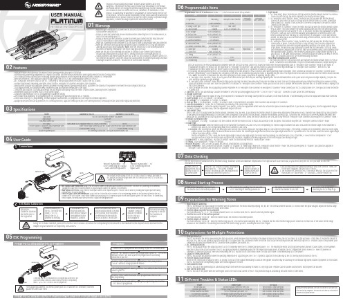
0103Specifications04User Guide05ESC Programming06Programmable Items07Data CheckingProgrammable Item List of Platinum 60A V4 ESC. (“*” in the form below indicate factory defaults. )USER MANUALHV 130A V4 / HV 130A OPTO V4Brushless Electronic Speed Controller1. Flight Mode:1.1 In “Fixed-wing” mode, the motor will start up when the throttle amount reaches 5% or above. There is no soft start-up, the motor responds to the throttle increase rapidly.1.2 In “Helicopter (Linear Throttle)” mode, the motor will start up when the throttle amount reaches 5% and it will start up in a soft way with the throttle (from 0 to 100%) acceleration time is fixed to 3.5 seconds. It will accelerate to the RPM corresponds to the specific throttle amount at the fixed rate.1.3 In “Helicopter (Elf Governor)” mode, the motor will start up when the throttle amount reaches 40% or above. And it will complete the speed standardization and enter the speed-governing operation in the preset start-up time (4~25s). In this mode, the motor will standardize its speed every time it starts up. Due to different discharge rates/capabilities of different batteries, the RPM you standardize each time may be a little different. In consequence, at the same throttle amount, the RPM may be a bit different when using different batteries, but this won’t affect the speed-governing effect.1.4 In “Helicopter (Store Governor)” mode, the motor will start up when the throttle amount reaches 40% or above. It will also start up in a very soft way. And it will also complete the speed standardization and enter the speed-governing operation in the preset start-up time. In this mode, the motor will only standardize its speed the first time when it starts up. When performing RPM standardization for the first time, we recommend using a fully-charged battery with good discharge capability. After the RPM standardization, change another battery to fly your aircraft. At the same throttle amount, the RPM should be the same as the RPM of the first flight. For consistent control feel, we recommend using this mode. About RPM Standardization & OthersI. The motor will enter the soft start-up when user switches the throttle amount from 0 to 40% or above (50%throttle is recommended). The pitch of main blades should be 0 degree during the• High performance microprocessor for excellent motor speed-governing and super soft start-up.• Microprocessor powered by independent DC regulator has better anti-interference performance, which greatly reduces the risk of losing control.• DEO (Driving Efficiency Optimization) Technology adopted greatly improves throttle response & driving efficiency, reduces ESC temperature.• New switch-mode BEC with adjustable output voltage ranges from 5V to 8V and continuous/peak current of 10A/25A.• BEC is separated from other circuits of the ESC, it will keep its normal output when the MOSFET board of the ESC is burnt. • Multiple flight modes: Fixed-wing, Helicopter (Linear Throttle), Helicopter (Elf Governor),Helicopter (Store Governor).• New governor program with adjustable governor parameter P/I brings excellent speed-governing effect, guarantees the stability of the propeller’s revs when the load changes dramatically. • Data logging records the standardized RPM, minimum voltage and maximum temperature of the flight.• "Restart in auto rotation" can manually interrupt the auto rotation and quickly restart the motor to avoid crashes caused by incorrect operations. • Independent output port for RPM (that is: motor speed) signals.• Separate programming port for ESC programming or parameter setting.• WIFI module (sold separately) for programming the ESC wirelessly with your smart phone (IOS or Android).• Online data checking, ESC programming, firmware upgrade (Multifunction LCD program box or WIFI Express is needed) supported.• Multiple protections like start-up protection, ESC thermal protection, capacitor thermal protection, over-current protection, overload protection, and throttle signal loss protection.Model Applications Input Voltage Cont./Peak Current (10s)BEC OutputThrottle Signal/BEC Output/RPM Signal Transmission WiresSize/WeightSeparate Programming PortPlatinum HV 130A V4White Throttle Signal Wire/Red & Black BEC Output Wires/Yellow RPM Signal Transmission WireFor connecting Multifunction LCD Program Box/WIFI module or fanSwitch-mode, 5V-8V Adjustable (Step:0.1V), 10A/25A Cont./Peak101x45.5x27mm / 168.5gProgrammingConnect the LCD program box and a battery to your ESC as shown above.successfully connected to your ESC.relates to the ESC.main blades =R ÷ Motor Poles ÷ 2 ÷ Gear Ratio × Throttle Amount (%).channel on the VBAR system. About which channel you should plug it in, it depends on your receiver and flybarless system. The White wire is for transmitting Program Your ESC with a WIFI Express: For detailed information, please refer to the user manual of WIFI Express.The ESC will record the standardized RPM, minimum voltage, maximum current and maximum temperatures of the flight but won’t save these data, so you need to keep the ESC on if you want to check theinformation of the flight.08Normal Start-up ProcessTurn on the transmitter, and then move the throttle stick to the bottom position.After connected to a battery, the ESC will emit “♪123” indicating it’s normally powered on.The motor will emit several beeps to indicate the number of LiPo cells.The motor emits a long beep indicating the ESC is ready to go.09Explanations for Warning Tones1. Input voltage is abnormal:The ESC will measure the input voltage the moment when it’s powered on. The motor will keep beeping “BB, BB, BB” (the interval between two BBs is 1 second) when the input voltage is beyond the normal range. The warning tone won’t stop until the voltage turns normal. 2. Throttle signal loss protection is activated:The motor will beep “B-, B-, B-” (the interval between two B-s is 2 seconds) when the ESC doesn’t detect any throttle signal. 3. Throttle stick is not at the bottom position:The motor will beep “B-B-B-B-B-” when the throttle stick is not moved to the bottom position.4. Throttle range is to narrow:The motor will beep “B-B-B-B-B-” when the throttle range you set is too narrow (when designing this ESC, it requires that the entire throttle range you set cannot be less than 50% of the whole throttle range available on the transmitter.) The warning tone indicates the throttle range you set is void and you need to set it again.10Explanations for Multiple Protections11Different Troubles & Status LEDs1. Start-up Protection:The ESC will monitor the motor speed during the start-up process. When the speed stops increasing or the speed increase is not stable, the ESC will take it as a start-up failure. At that time, if the throttle amount is less than 15%, the ESC will automatically try to restart up; if it is larger than 15%, you need to move the throttle stick to back the bottom position and then restart up the ESC. (Possible causes of this problem: poor connection/ disconnection between the ESC and motor wires, propellers are blocked, etc.)2. ESC Thermal Protection:The ESC will gradually reduce the output but won’t cut it off completely when the ESC temperature goes above 110℃. For ensuring the motor can still get some power and won’t cause crashes, so the maximum reduction is about 50% of the full power. The ESC will gradually resume its maximum power after the temperature lowers down. In addition, the ESC temperature cannot exceed 70℃ when it’s powered on. Otherwise, it cannot be started up. (Here we are describing the ESC’s reaction in soft cutoff mode, while if in hard cutoff mode; it will immediately cut off the power.) 3. Capacitor Thermal Protection:The ESC will activate this protection when the operating temperature of capacitors goes over 130℃. It protects capacitors in the same way as the ESC thermal protection does to the ESC .4. Throttle Signal Loss Protection:When the ESC detects loss of signal for over 0.25 second, it will cut off the output immediately to avoid an even greater loss which may be caused by the continuous high-speed rotation of propellers or rotor blades. The ESC will resume the corresponding output after normal signals are received. 5. Overload Protection:The ESC will cut off the power/output or automatically restart itself when the load suddenly increases to a very high value. (Possible cause to sudden load increase is that propellers are blocked.)6. Over-current Protection:The ESC will cut off the power when the current gets close to the short circuit current (of 400A). This protection may be activated by the burnt motor or some others.soft start-up process, the RPM standardization completes when the soft start-up ends, and the ESC makes the motor enter the speed-governing state. In “Helicopter (Store Governor)” mode, if user wants to re-standardize the speed, he needs to set the flight mode to “Helicopter (Elf Governor)” and save this mode first, and then reset the flight mode back to “Helicopter (Store Governor)”, then the ESC will re-standardize the motor speed when the motor rotates for the first time after the ESC is powered off and then on again.II. For ensuring the speed-governing effect, we recommend setting the throttle amount to 85% or below in both speed-governing modes (Helicopter (Store Governor) & Helicopter (Elf Governor)), so there will besufficient compensating room to maintain the consistency of the RPM. We recommend replacing the motor or adjusting the gear ratio if the expected RPM still cannot be reached when the throttle amount exceeds 85%. (Note: You need to re-standardize the RPM after replacing the motor, blades, body frame or adjusting the gear ratio.)III. In “Helicopter (Store Governor)” mode, if you fly your aircraft with another pack that has poor discharge capability after the RPM standardization (with a pack which has good discharge capability), the pack has poor discharge capability will get damaged.IV. In “Helicopter (Store Governor)” mode, different battery packs can bring the same stable RPM only if they have the same cell count. This won’t change even when you change the battery pack. However, battery packs with different cell count don’t have the same effect. For instance, in “Helicopter (Store Governor)” mode, you can not use a 4S to calibrate the motor RPM and then use a 6S to drive the motor, hoping it can run at the same RPM.V. User can decide the control feel via adjusting Governor Parameter P/I. In “Helicopter (Store Governor) or Helicopter (Elf Governor)” mode, connect your ESC to a smart phone or PC, then you can check the throttle vs speed chart.2. LiPo Cells: The ESC will automatically calculate the number of LiPo cells you have plugged in as per the “3.7V/Cell” rule if “Auto Calc.” is selected. Or user can set this item manually. 3. Voltage Cutoff Type:The ESC will gradually reduce the output to 50% of the full power in 3 seconds after the voltage cutoff protection is activated, if soft mode is selected . It will immediately cut off all the output when hard mode is selected. 4. Cutoff Voltage: 2.8V-3.8V (custom), 3.0V (default).5. BEC Voltage: 5-8V (adjustable), 0.1V (step), 6V (default).6. Start-up Time: 4-25s (adjustable), 1s (step), 15s (default). (Note: It only functions in Helicopter (Store Governor) and Helicopter (Elf Governor))7. Governor Parameter P: Control the ESC maintaining the stability of the current motor speed.8. Governor Parameter I: Control the dynamic response. To be specific, control the supplement extent when the actual motor speed is below expectation. If you choose a very big value, then the supplement may be too much. If select a very small value, then the supplement may not sufficient.9. Auto Restart Time:the ESC will cut off its output when the throttle amount is between 25% and 40%. If you increase the throttle amount to above 40% within preset time period (0-90s), the motor will rapidly start up and accelerate to the speed (in the programmed Restart Acceleration Time) corresponds to the specific throttle amount, complete the shutdown and restart up . If you move the throttle stick to over 40% beyond the preset time period, the ESC will enter the soft start-up process. (Note: This function won’t effect unless the throttle amount is over 25% and it only effects in “Helicopter (Store Governor) and Helicopter (Elf Governor)” mode.)10. Restart Acceleration Time:1-3s (adjustable), 0.5s (step), 1.5s (default). This item controls the time the motor will cost to restart and accelerate to the full speed. (This function only effects in “Helicopter Governor Elf/Store” mode) 11. Brake Type:11.1 Proportional Brake: when the throttle range on the transmitter is between 20% and 100%, the corresponding ESC throttle output is between 0% and 100%.When the throttle range on the transmitter is between 20% and 0%, the corresponding brake force is between 0 and 100%.11.2 Reverse: after selecting this option, the RPM signal wire will turn into a reverse signal wire (the signal range is in line with the throttle range). After setting a channel on the transmitter, when the reverse signal length is above 20% signal length, the Reverse mode will be activated. The reverse signal length must be below 20% signal length when the ESC is powered on for the first time. When the reverse signal length is below 20% signal length, 0-100%throttle corresponds to “CW”; when the reverse signal length is above 20% signal length, the motor will stop spinning CW (and then spin CCW); at this time, 0-100% throttle corresponds to “CCW”. Any signal loss will activate the throttle signal loss protection, no matter it happens to the RPM signal wire or the throttle signal cable during the flight.12. Brake Force: 0-100% (adjustable), 1% (step), 0 (default). (Note: this function only effects in “Normal Brake” mode.)13. Timing: 0-30° (adjustable), 1° (step), 15° (default).14. Motor Rotation: CW/CCW. User can adjust this item via a multifunction LCD program box.15. DEO (Freewheel): User can decide this function “Enabled” or “Disabled” in “Fixed Wing” mode or in “Helicopter (Linear Throttle)” mode. This item has been preset to “Enabled” and cannot be adjusted in “Helicopter (Store Governor) and Helicopter (Elf Governor)” mode. This function can brings better throttle linearity.During the normal operation, the Blue LED on the ESC will turn solid after the start-up completes. The Red LED will come on at full throttle and dies out at partial throttle.。
Motorola 3.5 kHz 产品说明书

RVN4126 3.59100-386-9100-386/T DEVICERVN41772-CD2-3.5MCS/MTSRVN41821-CD2-3.5XTS3000/SABER PORTABLE YES RKN4046KHVN9085 3.51-20 R NO HLN9359 PROG. STAND RVN4057 3.532 X 8 CODEPLUG NO3080385B23 & 5880385B30 MDVN4965 3.59100-WS/T CONFIG KITRVN4053 3.5ASTRO DIGITAL INTERFACE NO3080385B23RVN41842-CD RKN4046A (Portable) 2-3.5ASTRO PORTABLE /MOBILE YES3080369B73 or0180300B10 (Mobile) RVN41831-CD3080369B732-3.5ASTRO SPECTRA MOBILE YES(Low / Mid Power)0180300B10 (High Power) RVN4185CD ASTRO SPECTRA PLUS MOBILE NO MANY OPTIONS; SEESERVICE BRIEF#SB-MO-0101RVN4186CD ASTRO SPECTRA PLUS MANY OPTIONS;MOBILE/PORTABLE COMB SEE SERVICE BRIEF#SB-MO-0101RVN4154 3.5ASTROTAC 3000 COMPAR.3080385B23RVN5003 3.5ASTROTAC COMPARATORS NO3080399E31 Adpt.5880385B34RVN4083 3.5BSC II NO FKN5836ARVN4171 3.5C200RVN4029 3.5CENTRACOM SERIES II NO VARIOUS-SEE MANUAL6881121E49RVN4112 3.5COMMAND PLUS NORVN4149 3.5COMTEGRA YES3082056X02HVN6053CD CT250, 450, 450LS YES AAPMKN4004RVN4079 3.5DESKTRAC CONVENTIONAL YES3080070N01RVN4093 3.5DESKTRAC TRUNKED YES3080070N01RVN4091 3.5DGT 9000 DESKSET YES0180358A22RVN4114 3.5GLOBAL POSITIONING SYS.NO RKN4021AHVN8177 3.5GM/GR300/GR500/GR400M10/M120/130YES3080070N01RVN4159 3.5GP60 SERIES YES PMLN4074AHVN9128 3.5GP300 & GP350RVN4152 3.5GP350 AVSRVN4150 3.5GTX YES HKN9857 (Portable)3080070N01(Mobile) HVN9025CD HT CDM/MTX/EX SERIES YES AARKN4083/AARKN4081RiblessAARKN4075RIBLESS NON-USA RKN4074RVN4098H 3.5HT1000/JT1000-VISAR YES3080371E46(VISAR CONV)RVN4151 3.5HT1000 AVSRVN4098 3.5HT1000/ VISAR CONV’L.YES RKN4035B (HT1000) HVN9084 3.5i750YES HLN-9102ARVN4156 3.5LCS/LTS 2000YES HKN9857(Portable)3080070N01(Mobile) RVN4087 3.5LORAN C LOC. RECV’R.NO RKN4021ARVN4135 3.5M100/M200,M110,M400,R100 includesHVN9173,9177,9646,9774YES3080070N01RVN4023 3.5MARATRAC YES3080070N01RVN4019 3.5MAXTRAC CONVENTIONAL YES3080070N01RVN4139 3.5MAXTRAC LS YES3080070N01RVN4043 3.5MAXTRAC TRK DUPLEX YES3080070N01RVN4178CD MC SERIES, MC2000/2500DDN6124AW/DB25 CONNECTORDDN6367AW/DB9 CONNECTOR RVN41751-CD Rib to MIC connector 1-3.5MCS2000 RKN4062BRVN41131-3.5MCS2000RVN4011 3.5MCX1000YES3000056M01RVN4063 3.5MCX1000 MARINE YES3000056M01RVN4117 3.5MDC/RDLAP DEVICESRVN4105 3.5MOBILE PROG. TOOLRVN4119 3.5MOBITEX DEVICESRVN4128 3.5MPT1327-1200 SERIES YES SEE MANUALRVN4025 3.5MSF5000/PURC/ANALOG YES0180355A30RVN4077 3.5MSF5000/10000FLD YES0180355A30RVN4017K 3.5MT 1000YES RTK4205CRVN4148 3.5MTR 2000YES3082056X02RVN4140 3.5MTRI 2000NORVN41761-CD MTS2000, MT2000*, MTX8000, MTX90001-3.5*programmed by DOS which is included in the RVN4176RVN4131 3.5MTVA CODE PLUG FIXRVN4142 3.5MTVA DOCTOR YES3080070N01RVN4131 3.5MTVA3.EXERVN4013 3.5MTX800 & MTX800S YES RTK4205CRVN4097 1-CD MTX8000/MTX9000,MTS2000,MT2000*,* programmed by DOS which is included in the RVN4176HVN9067CD MTX850/MTX8250MTX950,MTX925RVN4138 3.5MTX-LS YES RKN4035DRVN4035 3.5MX 1000YES RTK4203CRVN4073 3.5MX 800YES RKN4006BHVN9395 P100, P200 LB, P50+, P210, P500, PR3000RVN4134 3.5P100 (HVN9175)P200 LB (HVN9794)P50+ (HVN9395)P210 (HVN9763)P500 (HVN9941)PR3000 (HVN9586)YES RTK4205HVN9852 3.5P110YES HKN9755A/REX1143 HVN9262 3.5P200 UHF/VHF YES RTK4205RVN4129 3.5PDT220YVN4051 3.5PORTABLE REPEATER Portable rptr.P1820/P1821AXRVN4061C 3.5PP 1000/500NO3080385B23 & 5880385B30 RVN5002 3.5QUANTAR/QUANTRO NO3O80369E31RVN4135 3.5R100 (HVN9177)M100/M200/M110/M400YES0180358A52RVN4146 3.5RPM500/660RVN4002 3.5SABER YES RTK4203CRVN4131 3.5SETTLET.EXEHVN9007 3.5SM50 & SM120YESRVN4039 3.5SMART STATUS YES FKN5825AHVN9054 3.5SOFTWARE R03.2 P1225YES3080070N01HVN9001 3.5SOFTWARE R05.00.00 1225LS YES HLN9359AHVN9012 3.5SP50RVN4001N 3.5SPECTRA YES3080369B73 (STANDARD)0180300B10 (HIGH POWER) RVN4099 3.5SPECTRA RAILROAD YES3080369B73RVN4110 3.5STATION ACCESS MODULE NO3080369E31RVN4089A 3.5STX TRANSIT YES0180357A54RVN4051 3.5SYSTEMS SABER YES RTK4203BRVN4075 3.5T5600/T5620 SERIES NO3080385B23HVN9060CD TC3000, TS3000, TR3000RVN4123 3.5VISAR PRIVACY PLUS YES3080371E46FVN4333 3.5VRM 100 TOOLBOX FKN4486A CABLE &ADAPTORRVN4133 3.5VRM 500/600/650/850NORVN4181CD XTS 2500/5000 PORTABLES RKN4105A/RKN4106A RVN41002- 3.5XTS3000 ASTRO PORTABLE/MOBILERVN4170 3.5XTS3500YES RKN4035DRIB SET UPRLN4008E RADIO INTERFACE BOX (RIB)0180357A57RIB AC POWER PACK 120V0180358A56RIB AC POWER PACK 220V3080369B71IBM TO RIB CABLE (25 PIN) (USE WITH XT & PS2)3080369B72IBM TO RIB CABLE (9 PIN)RLN443825 PIN (F) TO 9 PIN (M) ADAPTOR (USE W/3080369B72 FOR AT APPLICATION) 5880385B308 PIN MODULAR TO 25 PIN ”D” ADAPTOR (FOR T5600 ONLY)0180359A29DUPLEX ADAPTOR (MOSTAR/TRAXAR TRNK’D ONLY)Item Disk Radio RIB Cable Number Size Product Required Number Item Disk Radio RIB Cable Number Size Product Required NumberUtilizing your personal computer, Radio Service Software (RSS)/Customer Programming Software (CPS)/CustomerConfiguration Software (CCS) enables you to add or reprogram features/parameters as your requirements change. RSS/CPS/CCS is compatible with IBM XT, AT, PS/2 models 30, 50, 60 and 80.Requires 640K RAM. DOS 3.1 or later. Consult the RSS users guide for the computer configuration and DOS requirements. (ForHT1000, MT/MTS2000, MTX838/8000/9000, Visar and some newer products —IBM model 386, 4 MEG RAM and DOS 5.0 or higher are recommended.) A Radio Interface Box (RIB) may be required as well as the appropriate cables. The RIB and cables must be ordered separately.Licensing:A license is required before a software (RVN) order is placed. The software license is site specific (customer number and ultimate destination tag). All sites/locations must purchase their own software.Be sure to place subsequent orders using the original customer number and ship-to-tag or other licensed sites; ordering software without a licensed customer number and ultimate tag may result in unnecessary delays. To obtain a no charge license agreement kit, order RPX4719. To place an order in the U.S. call 1-800-422-4210. Outside the U.S., FAX 847-576-3023.Subscription Program:The purchase of Radio ServiceSoftware/Customer Programming/Customer ConfigurationSoftware (RVN & HVN kits) entitles the buyer/subscriber to three years of free upgrades. At the end of these three years, the sub-scriber must purchase the same Radio Service Software kit to receive an additional three years of free upgrades. If the sub-scriber does not elect to purchase the same Radio Service Software kit, no upgrades will be sent. Annually a subscription status report is mailed to inform subscribers of the RSS/CPS/CCS items on our database and their expiration dates.Notes:1)A subscription service is offered on “RVN”-Radio Service Software/Customer Programming/Customer Configuration Software kits only.2)“RVN” software must only be procured through Radio Products and Services Division (RPSD). Software not procured through the RPSD will not be recorded on the subscription database; upgrades will not be mailed.3)Upgrades are mailed to the original buyer (customer number & ultimate tag).4)SP software is available through the radio product groups.The Motorola General Radio Service Software Agreement is now available on Motorola Online. If you need assistance please feel free to submit a “Contact Us” or call 800-422-4210.SMART RIB SET UPRLN1015D SMART RIB0180302E27 AC POWER PACK 120V 2580373E86 AC POWER PACK 220V3080390B49SMARTRIB CABLE (9 PIN (F) TO 9 PIN (M) (USE WITH AT)3080390B48SMARTRIB CABLE (25 PIN (F) TO 9 PIN (M) (USE WITH XT)RLN4488ASMART RIB BATTERY PACKWIRELESS DATA GROUP PRODUTS SOFTWARERVN4126 3.59100-386/9100T DEVICES MDVN4965 3.59100-WS/T CONFIG’TN RVN41173.5MDC/RDLAP DEVICESPAGING PRODUCTS MANUALS6881011B54 3.5ADVISOR6881029B90 3.5ADVISOR ELITE 6881023B20 3.5ADVISOR GOLD 6881020B35 3.5ADVISOR PRO FLX 6881032B30 3.5BR8506881032B30 3.5LS3506881032B30 3.5LS5506881032B30 3.5LS7506881033B10 3.5LS9506881035B20 3.5MINITOR III8262947A15 3.5PAGEWRITER 20008262947A15 3.5PAGEWRITER 2000X 6881028B10 3.5TALKABOUT T3406881029B35 3.5TIMEPORT P7308262947A15 3.5TIMEPORT P930NLN3548BUNIVERSAL INTERFACE KITItem Disk Radio NumberSize Product。
Hikvision DS-7200HQHI-K1 商品说明书
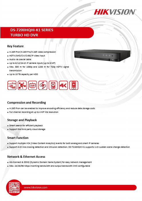
Key Feature● H.265 Pro+/H.265 Pro/H.265 video compression ● HDTVI/AHD/CVI/CVBS/IP video input ● Audio via coaxial cable● Up to 6/12/24-ch IP camera inputs (up to 6 MP) ● Max.800 m for 1080p and 1200 m for 720p HDTVI signaltransmission● Up to 10 TB capacity per HDDCompression and Recording● H.265 Pro+ can be enabled to improve encoding efficiency and reduce data storage costs ● Full channel recording at up to 4 MP lite resolutionStorage and Playback● Smart search for efficient playback ● Support the third party cloud storageSmart Function● Support multiple VCA (Video Content Analytics) events for both analog and smart IP cameras● Support 4-ch line crossing detection and intrusion detection; DS-7216HQHI-K1 supports 1-ch sudden scene change detectionNetwork & Ethernet Access● Hik-Connect & DDNS (Dynamic Domain Name System) for easy network management ● Max. 24/48/96 Mbps incoming bandwidth and output bandwidth limit configurableSpecificationModel DS-7204HQHI-K1DS-7208HQHI-K1DS-7216HQHI-K1 Perimeter Protection¹Line Crossing Detection/ Intrusion Detection 2-chEnhanced VCA mode on: 4-ch2-chEnhanced VCA mode on: 4-ch2-chEnhanced VCA mode on: 4-chRecordingVideo compression H.265 Pro+/H.265 Pro/H.265/H.264+/H.264Encoding resolution When 1080p lite mode is not enabled:4 MP lite/3 MP/1080p/720p/VGA/WD1/4CIF/CIF When 1080p Lite mode is enabled:4 MP lite/3 MP/1080p lite/720p lite/VGA/WD1/4CIF/CIFFrame rate Main stream:When 1080p Lite mode is not enabled:For 4 MP stream access:4 MP lite@15fps; 1080p lite/720p/WD1/4CIF/VGA/CIF@25fps (P)/30fps (N)For 3 MP stream access: 3 MP/1080p/720p/VGA/WD1/4CIF/CIF@15fpsFor 1080p stream access:1080p/720p@15fps; VGA/WD1/4CIF/CIF@25fps (P)/30fps (N)For 720p stream access: 720p/VGA/WD1/4CIF/CIF@25fps (P)/30fps (N)When 1080p Lite mode is enabled:4 MP lite/3 MP@15fps; 1080p lite/720p lite/VGA/WD1/4CIF/CIF@25fps (P)/30fps (N) Sub-stream:WD1/4CIF@12fps; CIF@25fps (P)/30fps (N)Video bit rate32 Kbps to 6 Mbps Dual stream SupportStream type Video, Video & Audio Audio compression G.711uAudio bit rate64 KbpsVideo and AudioIP video input21-ch (up to 5-ch)Enhanced IP mode on:2-ch (up to 6-ch), each upto 4 Mbps2-ch (up to 10-ch)Enhanced IP mode on:4-ch (up to 12-ch), each upto 4 Mbps2-ch (up to 18-ch)Enhanced IP mode on:8-ch (up to 24-ch), each upto 4 MbpsUp to 6 MP resolutionSupport H.265+/H.265/H.264+/H.264 IP camerasAnalog video input 4-ch8-ch16-ch BNC interface (1.0 Vp-p, 75 Ω), supporting coaxitron connectionHDTVI input 4 MP, 3 MP, 1080p30, 1080p25, 720p60, 720p50, 720p30, 720p25*: The 3 MP signal input is only available for channel 1 of DS-7204HQHI-K1, for channel 1/2 of DS-7208HQHI-K1, and for channel 1/2/3/4 of DS-7216HQHI-K1.AHD input 4 MP, 1080p25, 1080p30, 720p25, 720p30 HDCVI input 4 MP, 1080p25, 1080p30, 720p25, 720p30CVBS input PAL/NTSCCVBS output1-ch, BNC (1.0 Vp-p, 75 Ω), resolution: PAL: 704 × 576, NTSC: 704 × 480VGA output1-ch, 1920 × 1080/60Hz, 1280 × 1024/60Hz, 1280 × 720/60Hz, 1024 × 768/60HzHDMI output 1-ch, 1920 × 1080/60Hz, 1280 × 1024/60Hz, 1280 ×720/60Hz, 1024 × 768/60Hz1-ch, 4K (3840 ×2160)/30Hz, 2K (2560 ×1440)/60Hz, 1920 ×1080/60Hz, 1280 ×1024/60Hz, 1280 ×720/60Hz, 1024 ×768/60HzAudio input 1-ch, RCA (2.0 Vp-p, 1 KΩ)4-ch via coaxial cable8-ch via coaxial cable16-ch via coaxial cableAudio output1-ch, RCA (Linear, 1 KΩ)Two-way audio1-ch, RCA (2.0 Vp-p, 1 KΩ) (using the first audio input) Synchronous playback4-ch8-ch16-ch NetworkTotal bandwidth72 Mbps96 Mbps128 Mbps Incoming bandwidth(Enhanced IP mode)24 Mbps48 Mbps96 Mbps Remote connection3264128Network protocol TCP/IP, PPPoE, DHCP, Hik-Connect, DNS, DDNS, NTP, SADP, NFS, iSCSI, UPnP™, HTTPS, ONVIFNetwork interface1, RJ45 10M/100M self-adaptive Ethernet interface 1, RJ4510M/100M/1000M self-adaptive Ethernet interfaceAuxiliary interfaceSATA 1 SATA interfaceCapacity Up to 10 TB capacity for each disk Serial interface RS-485 (half-duplex)USB interface 2 × USB 2.0Front panel: 1 × USB 2.0 Rear panel: 1 × USB 3.0Alarm in/out N/AGeneralPower supply12 VDC, 1.5 A12 VDC, 1.5 A12 VDC, 3.33 A Consumption(without HDD)≤ 6 W≤ 7.5 W≤ 25 WWorking temperature-10 °C to +55 °C (+14 °F to +131 °F)Working humidity10% to 90%Dimension (W × D × H)315 × 242 × 45 mm (12.4 × 9.5 × 1.8 inch)Weight (without HDD)≤ 1.16 kg (2.6 lb)≤ 1.78 kg (3.9 lb)≤ 2 kg (4.4 lb)Note:1: Enabling enhanced VCA mode will maximize the connectable channel number for perimeter protection (line crossing detection and intrusion detection), but disable 2K/4K HDMI output resolution and 4 MP signal input.2: Enhanced IP mode might be conflicted with smart events (perimeter protection) or other functions, please refer to the user manual for details.Physical Interface*: The rear panel of DS-7204/7208HQHI-K1 provides 4/8 video input interfaces.No.Description No.Description1Video and Coaxial Audio In7LAN Network Interface2AUDIO IN, RCA Connector8RS-485 Serial Interface3AUDIO OUT, RCA Connector9Power Input4VGA Interface10Power Switch5HDMI Interface11GND6USB Interface12VIDEO OUTAvailable ModelDS-7204HQHI-K1, DS-7208HQHI-K1, DS-7216HQHI-K104250002010224。
650驱动器基本启动指南说明书
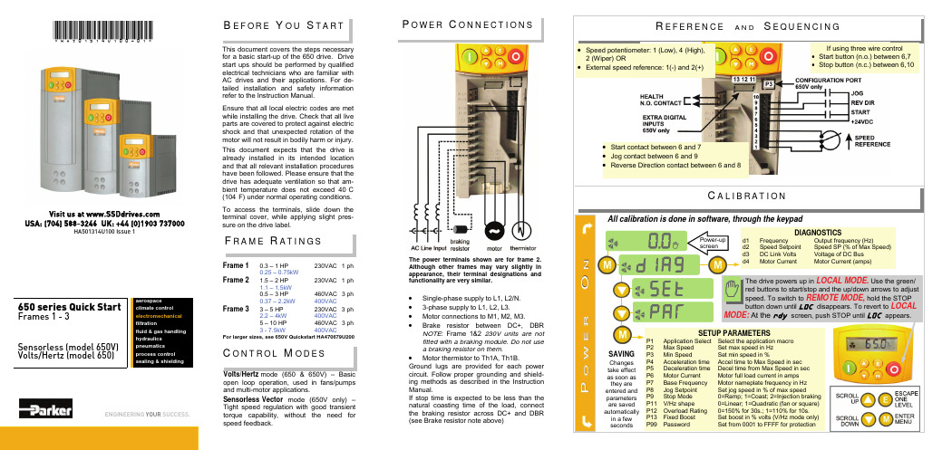
B E F O R E Y O U S TA R TThis document covers the steps necessary for a basic start-up of the 650 drive. Drive start ups should be performed by qualified electrical technicians who are familiar with AC drives and their applications. For de-tailed installation and safety information refer to the Instruction Manual.Ensure that all local electric codes are met while installing the drive. Check that all live parts are covered to protect against electric shock and that unexpected rotation of the motor will not result in bodily harm or injury. This document expects that the drive is already installed in its intended location and that all relevant installation procedures have been followed. Please ensure that the drive has adequate ventilation so that am-bient temperature does not exceed 40°C (104°F) under normal operating conditions.To access the terminals, slide down the terminal cover, while applying slight pres-sure on the drive label.•Single-phase supply to L1, L2/N. •3-phase supply to L1, L2, L3.•Motor connections to M1, M2, M3.•Brake resistor between DC+, DBR NOTE : Frame 1&2 230V units are not fitted with a braking module. Do not use a braking resistor on them .•Motor thermistor to Th1A, Th1B.Ground lugs are provided for each power circuit. Follow proper grounding and shield-ing methods as described in the Instruction Manual.If stop time is expected to be less than the natural coasting time of the load, connect the braking resistor across DC+ and DBR (see Brake resistor note above)The power terminals shown are for frame 2. Although other frames may vary slightly in appearance, their terminal designations and functionality are very similar.Frame 1 0.3 – 1 HP 230VAC 1 ph0.25 – 0.75kWFrame 2 1.5 – 2 HP 230VAC 1 ph 1.1 – 1.5kW0.5 – 3 HP 460VAC 3 ph 0.37 – 2.2kW 400VACFrame 3 3 – 5 HP 230VAC 3 ph 2.2 – 4kW 400VAC5 – 10 HP 460VAC 3 ph 3 - 7.5kW 400VACFor larger sizes, see 650V Quickstart HA470679U200P OW E R C O N N E C T I O N S*HA501314U100-01*650 series Quick StartFrames 1 - 3Sensorless (model 650V) Volts/Hertz (model 650)ENGINEERING YOUR SUCCESS.aerospaceclimate control electromechanical filtrationfluid & gas handling hydraulics pneumatics process control sealing & shieldingVolts/Hertz mode (650 & 650V) – Basic open loop operation, used in fans/pumps and multi-motor applications.Sensorless Vector mode (650V only) – Tight speed regulation with good transient torque capability, without the need for speed feedback.C O N T R O L M ODE SF R A M E R AT I NG SAll calibration is done in software, through the keypadC A L I B R AT I O NIf using three wire control •Start button (n.o.) between 6,7 •Stop button (n.c.) between 6,10Speed potentiometer: 1 (Low), 4 (High),External speed reference: 1(-) and 2(+)Start contact between 6 and 7 Jog contact between 6 and 9Reverse Direction contact between 6 and 8Visit us at USA: (704) 588-3246 UK: +44 (0)1903 737000HA501314U100 Issue 1S E R I A L C O M M SC LO N I N G650 and 650V drives may be cloned using the 6514 Clone option that plugs into the keypad slot. Settings include to/from, I/O configuration and full/part transfer.The 650 has additional features which can beaccessed via the drive menu, or for the 650V using DSE Lite. Refer to the product manual for details. Flycatching - When enabled, lets the drive start into a spinning load by doing a frequency search. Skip Frequencies – Two selectable avoidance frequencies and associated window for each. PID – Provides closed loop process control S-Ramp – When enabled, introduces a second order slope to the ramp for smoother transitions. Configurable Outputs – The digital outputs on the 650 can be configured to pick one of 6 parameters. The outputs on the 650V are totally configurable. Auto Restart - After a fault, the drive attempts a number of restarts after a settable delay.Custom Screens - Allows the use of a Custom parameter to be displayed. (650V only)Encoder – Terminals 12 &13 (650V only) can be used for a quadrature (not complementary) encoder input for steady-state speed feedback.Associated Literature650 Installation Manual HA464828Uxxx 650 Software Manual HA467872Uxxx 650V Installation Manual HA467649Uxxx 650V Software Manual HA501306UxxxThe 6513 Serial Communication option can be plugged into the keypad slot. It can be used to exchange information between the Master and Slave drives in RS485/232 format, up to 32 units can be connected together. Front panel LED indicators provide status and health indication.A DVA N C E D F E AT U R E S。
10KV高压无线核相仪

准确度:同相误差≤10°,不同相≤15°主机电源9V±2V采集器电源7.5V±1.5V采集器X、Y与主机的视距传输距离≤70米采集器采集的电压等级为0.22KV-500KV工作温度-35℃- +50℃可伸缩绝缘操作杆:缩态为600mm,伸态为3000mm包装箱尺寸:长×宽×高)650mm×250mm×100mm产品重量:主机重约0.3Kg,重约5Kg。
1、现场核相时,操作人员必须按照《电力安全工作规程》的标准要求进行操作。2、可伸缩绝缘操作杆的电压等级为 ≤ 220KV 。3、在≥66KV线路或电气设备上核相时,X和Y采集器应采取非接触方法核相。
1、主机显示有:无线高压核相仪、不同相、同相、角度、X、Y、 、2、采样速率3次/秒3、采用内置电源:主机采用的电池型号为NEDA/604/6F22、9V或同等型号的电池:X和Y采集器采用5节AG13、1.5V电池 4、工作环境:-35℃- +50℃,湿度:≤90%RH5、储存环境:-40℃- +55℃,湿度:≤95%RH6、10KV高压无线核相仪价格附件:1)铝合金包装箱一个2)带交流220V插头和测试线夹的测试线一条3)型号为6F22、9V电池一节4、型号为AG13、1.5V的钮扣电池10节5、说明书一本
无线高压核相仪性能指标
单击此处添加标题
无线高压核相仪系统组成及特点测试系统组成:主机(接收)、X采集器(发射)、Y采集器(发射)、针式和挂钩式两种采集头、可伸缩绝缘操作杆等所组成。(附件包括铝合金包装箱、备用电池、带插头的专用校验测试线夹)。本系统全部采用数字电路,功能齐全、功耗低,正常使用每年更换一次电池即可(因普通电池自然放电)。当X和Y采集器或主机电源电压低时,主机屏幕有低压告警显示。无线高压核相仪安全可靠X和Y采集器,将采集到的电压相位信号通过无线信号发往主机,具有可靠的高电压电气安全隔离性能。本产品全部采用数字电路,抗干扰性强、数据稳定准确。方便快捷X和Y采集器使用方便,主机具有自动关机功能。绝缘杆采用可伸缩式拉杆,现场核相时不需要任何连线,核相距离可达70米,并不受现场各种条件影响,全部核相过程只需两人在2分钟内就可完成。10KV高压无线核相仪价格仪更多功能可在两个不同的电压等级间进行核相,既可定性测量(同相、不同相),又可定量测量(两供电线路相角差如30°、60°等)。测量相序:正相序120°,逆相序240°。验电功能:当X或Y采集器的采集头接触到高压线路或电气设备的带电部分时,如线路或设备有电,主机则显示X或Y。
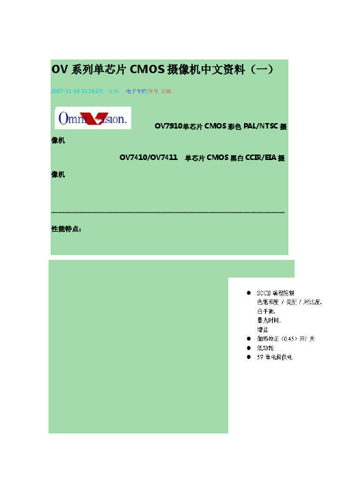
OV系列单芯片CMOS摄像机中文资料
电视机,视频监视器和其他75欧姆终端输入的视频设
备。OV7910 / OV7410 / OV7411视频摄像机是低功耗设
计,仅需要5V 直流供电。这两个产品非常合适于小体
感光阵列
NTSC:510*492像素
PAL:628*582像素
靶面尺寸
NTSC:4.69*3.54毫米
PAL:5.78*4.19毫米
单芯片1/3英寸
视频摄像机
全电视信号输
出:NTSC/ PAL 或
S-视频
分量电视信号
输出:RGB 或 YUV
灵敏度提升
(+18Db)/ AGC
关闭时
自动暴光控制
/ 自动增益控制/
自动白平衡
外部桢同步输
入
孔阑校正
视频会议
可视电视
视频电子邮件
PC 电脑眼 玩具 保安监视 医疗仪器 汽车尾视
VTO-P 视频峰值电平
-
2.3
2.4
-
VTO-B 视频黑电平
-
0.7
1.2
-
VSYNC 视频同步脉冲
-
0.7
0.4
-
幅度
RO 视频输出负载
75
75
单位
V V V Ohm
2. SCCB 总线 OV7910/OV7410/OV7411中的许多功能是设置寄存器都可以通过 SCCB 高
速 串行接口操作。通过将 SBB 管脚(管脚34)和 VDD 之间一个10K 电阻,即可 允许 SCCB 接口。当 SCCB 操作允许时(SBB=1),OV7910/OV7410/OV7411 图像传感器就以从设备方式工作,支持7位地址/数据和400K 位/秒的串行传输 速度。每一个字节,第一位是最高位,读写控制位是第一字节的最低位。协议
长虹IPC需要HK发货情况

注1:①申请人应根据第四章技术需求书中的技术要求,按包报出相应的选型产品型号,并须以该产品参加本项目后续产品技术测试和入围选型及谈判(如获得资格),若发现申请人在后续提交的响应文件中所报产品型号与本表中所报产品型号出现不一致的情况,则申请人的响应文件将被拒绝;②供应商所报产品型号数量必须严格按第四章<选型目录>中的规定报出,如有不符,则申请人的申请将为无效申请而被拒绝;③供应商所报产品的功能、技术指标不低于相应产品系列的要求。
注1:以上四款表格分别适用于本项目不同的包,请申请人按所报包分别填写不同的表格。
注2:①申请人必须将本表单独密封提交,但在装订成册的申请文件中不得再提供本表,否则将视为未实质性响应的申请文件而被拒绝。
采购人和采购代理机构将对各申请人提供的本表进行封存,在响应文件的评审阶段由评审委员会进行拆封。
②本表中的产品型号必须与申请人提供的附件2产品型号一览表中所报完全一致,如资格预审合格,申请人须以本表所报型号产品参加本项目后续产品技术测试和入围选型,申请人在后续提交的响应文件中所报产品型号和报价必须与其在本表中所报产品和报价相一致,否则其响应文件将视为未实质性响应的文件而被拒绝。
③本表中的报价均为产品运至交货地点的最终目的地价,均已包含售后服务(含指导安装、技术培训、原厂保修等)及达到和满足采购文件技术要求所需的全部费用。
申请人名称(公章):四川长虹电子系统有限公司
申请人代表签字:。
深圳希林产品介绍

Hilin Intelligence Electronic Co.,LTD第一部分:产品介绍第二部分:产品应用第三部分:产品操作说明HL-A901企业数据信息采集器,TCP/IP 协议,WiFi无线组网,不带电池HL-A902企业数据信息移动采集器,TCP/IP协议,WiFi无线组网,自带电池HL-B901企业数据信息采集器,TCP/IP协议,有线组网,不带电池HL-C901企业数据信息屏接收器,TCP/IP协议,无线接收HL-AT900考勤机TCP/IP协议,无线接收HL-AT800门禁机TCP/IP协议,无线接收(c.基本参数)(d.功能特点)(e.开发平台)uC/OS-IIμC/OS 和μC/OS-II 是专门为计算机的嵌入式应用设计的,绝大部分代码是用C语言编写的。
CPU 硬件相关部分是用汇编语言编写的、总量约200行的汇编语言部分被压缩到最低限度,为的是便于移植到任何一种其它的CPU 上。
用户只要有标准的ANSI 的C交叉编译器,有汇编器、连接器等软件工具,就可以将μC/OS-II嵌人到开发的产品中。
μC/OS-II 具有执行效率高、占用空间小、实时性能优良和可扩展性强等特点,最小内核可编译至2KB 。
μC/OS-II 已经移植到了几乎所有知名的CPU 上(f.可支持的二次开发语言)JAVAC-SHAP(C#)Visual BasicVisual C++PowerBuilder Delphi(g.可采集的数据模式)PS2接口扫描枪智能卡RFIDIO开关机床接口矩阵键盘温度湿度红外传感器(h.工作模式)A.实时模式:数据实时存储在服务器上;B:脱机模式:数据暂存在机器上,后台监控软件打开数据会自动上传数据;C:实时交互模式:终端数据实时上传,lcd显示、蜂鸣器、led指示灯、继电器等可能过后台控制。
(a.应用领域)服装加工鞋业制造考勤门禁注塑机管理汽车生产五金加工电力负荷监控自来水管网监测城市路灯监控远程抄表(b.基本组网样图)(c.Server Demo)ERP是英文Enterprise Resource Planning(企业资源计划)的简称ERP系统是指建立在信息技术基础上,以系统化的管理思想,为企业决策层及员工提供决策运行手段的管理平台。
武汉供货清单1126

26
赫斯曼
德国
10
终端交换机
OCTOPUS OS20-0010001M1MTREPHH
二层交换机,IP67防护等级,2个100M多模光口,8个10/100M M12端口
套
169
赫斯曼
德国
四、车站现场设备
1
自动售票机
TVM-02-WH6
台
228
华铭
中国
自动售票机(TVM)主要模块配置清单(单台)
序号
台
52
理光
中国
5
机柜
图腾K36042标配机柜
PDU电源、配线设施,底部支架
套
26
图腾
中国
6
紧急按钮控制模块及配件
华腾EB-W06紧急按钮控制器
套
26
华腾
中国
7
配电柜
(按图定制,非标)
含柜体、空开、防雷器件、漏电保护器等全部附件
个
52
森高电气
中国
8
配电箱
(按图定制,非标)
定制,含空开、防雷器件、漏电保器
套
1
联想/IBM
中国
7
设备监控及维修管理工作站
同一、5工作站规格型号一致
含桌椅
台
10
联想
中国
8
机柜
图腾K36042标配机柜
PDU电源、配线设施,底部支架
套
2
图腾
中国
9
车站服务器
同一、3防病毒服务器规格型号一致
套
1
联想/IBM
中国
10
PC工作站
同一、5工作站规格型号一致
含桌椅
套
1
EFLOW用户指南 Release 12.3说明书

Path
:
Online
: True
RestartNeeded : False
2. Set execution policy and verify.
Set-ExecutionPolicy -ExecutionPolicy AllSigned -Force
Get-ExecutionPolicy AllSigned
5
EFLOW User's Guide, Release 12.3
3. Download and install EFLOW.
$msiPath = $([io.Path]::Combine($env:TEMP, 'AzureIoTEdge.msi')) $ProgressPreference = 'SilentlyContinue' Invoke-WebRequest "https:∕∕aka.ms∕AzEFLOWMSI_1_4_LTS_X64" -OutFile $msiPath
▶ The Windows host OS with virtualization enabled ▶ A Linux virtual machine ▶ IoT Edge Runtime ▶ IoT Edge Modules, or otherwise any docker-compatible containerized application (runs on
深圳海伊视讯产品型录
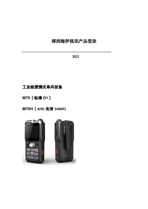
深圳海伊视讯产品型录2021工业级便携式单兵设备M70〔标清D1〕M70H〔AHD高清1080P)产品简介:该产品采纳工业级设计理念,使用高速处理器和嵌入式操作系统,集音视频、GPS、报警等传感器,可配置各种适应于不同应用场景的拔插型外置摄像头,协同后端功能完善的监控调度指挥系统实现针对户外移动式个体的远程调度指挥功能。
产品特点:1)工业级设计,IP542) 2.4英寸的高清LCD屏幕,图像细腻,色彩真实3)主机与摄像机分体设计,适合手持、腰胯、肩头佩戴等多种佩戴方式4)封装锂电池供电,便于充电和携带,可配套充电底座5)支持WIFI、移动网络自动切换、支持3G/4G网络、可选GPS或北斗定位模块6)超长工作时长,>=5个小时7)丰富的网络传输功能,包括实时预览、远程回放、远程下载、广播对讲、短信互动等功能8)多种传输画质可选9)支持Micro-SD卡,最大支持128G10)支持IP集群功能11)支持移动管控平台治理软件适应行业:交警、巡警、城管、海防、武警、保险回放支持播放、暂停、2、4、8、16倍速度快进或快退,支持文件选时播放屏幕参数尺寸 2.4 英寸类型TFT辨论率480*234无线传输内置3G/4G无线传输模块, 支持WCDMA、CDMA2000、TD-SCDMA、LTE-FDD/TDD制式可选;兼容GPRS, EDGE;内置WIFI;定位内置GPS或北斗〔可选〕系统升级支持Micro-SD卡升级外部接口USB从接口支持,用于数据导出电源及功耗电源治理手动开关机、支持手动关屏、超时自动关屏电池容量14.8Wh , 7.4V充电时长< 3小时工作时长>= 5小时工作环境温度-20℃~ +50℃湿度10% to 95%尺寸主机65(W) x130(H) x30(D) mm 附件整体图:迷你型单SD卡车载录像机M10H〔AHD高清720P〕产品简介:该产品是专为车载移动监控大众市场设计的一款高性价比的迷你型SD车载监控录像机。
NOTIFIRE WEB SERVER NWS-3 说明书

NWS-3NOTI•FIRE•NET™Web ServerDN-6928:C • A0-810GeneralThe NOTI•FIRE•NET™ Web Server(NWS-3) is a web-baseddevice that acts as an HTML server, allowing remote access tothe NOTI•FIRE•NET™ network via the Internet or an intranet.With the NWS-3 interface, users can view fire alarm controlpanel (FACP) event history, event status, device properties andother information based on access permissions defined by thesystem administrator. All data available on the NWS-3 is a“snapshot” of the data on the NOTI•FIRE•NET™ network atthe time the browser requested the information.The NWS-3 interfaces to the Internet/intranet using an IP-basedwire Ethernet connection.FeaturesFOR THE NOTI•FIRE•NET™ WEB SER ER ANDBROWSER CONFIGURATION TOOL•Access NOTI•FIRE•NET™ device statuses and properties remotely via the Internet or an intranet.•Automatically send up to 50 emails or text messages in response to any system event.•Compatible with standard and high speed NOTI•FIRE•NET™.•Unacknowledged Beep feature, if enabled, causes the com-puter browsing the NWS-3 to beep at three-second intervals if there are unacknowledged events in the Multiple Event List.•Compatible with NOTI•FIRE•NET™ version 5.0 and higher.•One NWS-3 supports multiple users.•Standard Ethernet over IP connection.•Y our system remains secure by installing the NWS-3 behind your network firewall.•Supports up to 64 operator and 64 administrator accounts.•Built-in password security and user-access record.•Multiple users can access the web server at the same time.•Supports standard Microsoft® Internet Explorer 8.0 or higher.•Intuitive Explorer-style user interface.•Ability to use V eriFire® Tools (version 3.0 or higher) for remote programming/configuration of the NWS-3 and ONYX® Series products.NOTE: No fire alarm control functions are permitted. The NWS-3 is an ancillary device and not intended for primary reporting.CompatibilityThe NWS-3 is compatible with NOTI•FIRE•NET™ version 5.0 and higher for the following panels and devices:•ONYX® Series.•AM2020/AFP1010 (version 5.0 SIB).•AFP-200 (events only).•AFP-300/AFP-400.•BACnet Gateway (events only).•NCS Network Control Station (events only).•NCA(-2) Network Control Annunciator (events only).•Compatible with high speed network HS-NCM version 1.0 and higher.NOTE: The NWS-3 is NOT intended as a primary annunciator and is ancillary in nature.System Requirements•NOTI•FIRE•NET™ Web Server (NWS-3).•NCM card.•Browser: Microsoft Internet Explorer, version 8.0 or higher.•JAVA version 6 or later.Agency Listings and ApprovalsThese listings and approvals apply to the NOTI•FIRE•NET™Web Server. In some cases, certain modules or applications may not be listed by certain approval agencies, or listing may be in process. Consult factory for latest listing status.•UL/ULC Listed: S635.•CSFM: 7165-0028:0247.•FDNY: COA#6045.NFN-GW-EM-3.JPGDN-6928:C • 08/15/2012 — Page 1 of 2Page 2 of 2 — DN-6928:C • 08/15/2012ONYX ®, NOTIFIER ®, and VeriFire ® are registered trademarks, and NOTI•FIRE•NET ™ and ONYXWorks ™ are trademarks of Honeywell International Inc. Microsoft ® and Windows ® are registered trademarks of Microsoft Corporation.©2012 by Honeywell International Inc. All rights reserved. Unauthorized use of this document is strictly prohibited.This document is not intended to be used for installation purposes. We try to keep our product information up-to-date and accurate. We cannot cover all specific applications or anticipate all requirements.All specifications are subject to change without notice.For more information, contact Notifier. Phone: (203) 484-7161, FAX: (203) 484-7118.System Architecture•Connect to the NOTI•FIRE•NET™ network. The NWS-3can be connected to the NOTI•FIRE•NET™ network via the Network Control Module (NCM) network interface card (see diagram).•The NWS-3 can be directly connected to ONYX® series pan-els for stand-alone panel applications.•The NWS-3 can also be connected to high speed networks using HS-NCM network interface.System Architecture DiagramNWS -3 HS-NCM OR NCM ARCHITECTURECAB-4 Cabinet with NWS-3 Assembly and HS-NCM W/SF/MF or NCM W/F BoardNFN NetworkInternet/IntranetSupported FACP Supported FACPPC Browser InterfaceHS-NCM-W/SF/MFor NCM-W/FHS-NCM-W/SF/MF or NCM-W/FNWS-3 DIRECT PANEL ARCHITECTUREInternet/IntranetPC Browser InterfaceSupported ONYX Series FACPwith Web Server Assembly。
Honeywell楼宇对讲产品介绍

RF
门锁 分机:最多 5 个 AC220V
AC220V
AC220V
厨房电视电话
电话
6芯 RS-485
AC220V
6芯 RS-485 8芯 RS-485
浴室电话:最多 2 个
单户门口机
双核 触点
4芯 音频/视频传输 3芯 信号 2芯 触点
视/音频通信
小门口机
厨房电视
浴室电话
控制 本地服务器 本地
温度控制器 电话抄表服务器 APT 服务器 管理员机 窗帘 灯光 门锁 煤气阀
安防
单元门口机 安防服务器
停车场服 务器
门磁
红外探头
火灾
煤气
紧急按钮
提供给客户满意完善的社区安防和家居控制解决方案/引领数码未来家居生活模式
住房内配置
HGW-102 终端安装在家中(通常在起居室内),与包括分机、厨房电视电话、单户门口机、浴室电话以及数个探测器在内 的多个设备相连。
September 12, 2014
Honeywell楼宇对讲产品介绍
© ABB Group September 12, 2014 | Slide 0
产品家族
小区产品 分类
Honeywell产品 应用对象 高档别墅
智能家居
•HS-7000V
顶级公寓
•IS-6500 ( tcp / ip )
别墅 顶级、高档公寓
控制终端
屏幕: 7” TFT LCD • 功能 - 可视对讲 - 空调/灯光/窗帘等控制功能 - 安防功能
屏幕: 10” TFT LCD •更加人性化的操作界面 •定制功能更强 •10寸屏
富士胶片 内镜系列 双气囊肠镜 说明书

Iris Image storage Power rating Dimensions W×H×D
Weight DICOM
HD-SDIHDTV 1080i 2ch
DVI Digital Visual Interface
1280×1024p Ethernet100 / 10Base RGB1280×1024p SDTV 120V/NTSC,230V/PAL
Less invasiveness
EPX-3500HD
Tube kit
Over-tubes Balloons
Hood
System Configuration
Using silicone rubber accessories
New
Balloon Controller: PB-30/PB-20
Tube Kit: TY-500*
DBE 3.2mm
Close Focus
Double-balloon endoscope suitable for both observation and treatment. The 3.2mm instrument channel diameter enables improved suction performance and supports a wider variety of procedures including hemostasis and balloon dilatation. The new High Resolution Super CCD ensures vivid and high quality images, and the new optical lens enables the observation range of 2-100mm and a wide-angle 140° field of view.
Baumer POG 10 增量编码器商品说明书
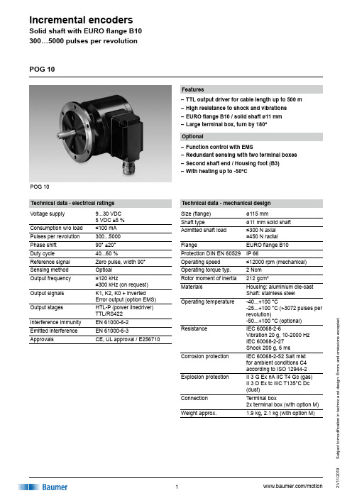
POG 10Features–TTL output driver for cable length up to 500 m –High resistance to shock and vibrations –EURO flange B10 / solid shaft ø11 mm –Large terminal box, turn by 180°Technical data - electrical ratings Voltage supply 9...30 VDC 5 VDC ±5 %Consumption w/o load ≤100 mA Pulses per revolution 300...5000Phase shift 90° ±20°Duty cycle 40...60 %Reference signal Zero pulse, width 90°Sensing method OpticalOutput frequency ≤120 kHz≤300 kHz (on request)Output signals K1, K2, K0 + inverted Error output (option EMS)Output stages HTL-P (power linedriver) TTL/RS422Interference immunity EN 61000-6-2Emitted interference EN 61000-6-3ApprovalsCE, UL approval / E256710POG 10Technical data - mechanical design Size (flange)ø115 mmShaft typeø11 mm solid shaft Admitted shaft load ≤300 N axial ≤450 N radial FlangeEURO flange B10Protection DIN EN 60529IP 66Operating speed ≤12000 rpm (mechanical)Operating torque typ. 2 Ncm Rotor moment of inertia 212 gcm²MaterialsHousing: aluminium die-cast Shaft: stainless steelOperating temperature-40...+100 °C-25...+100 °C (>3072 pulses per revolution)-50...+100 °C (optional)ResistanceIEC 60068-2-6Vibration 20 g, 10-2000 Hz IEC 60068-2-27 Shock 200 g, 6 ms Corrosion protection IEC 60068-2-52 Salt mist for ambient conditions C4 according to ISO 12944-2Explosion protectionII 3 G Ex nA IIC T4 Gc (gas) II 3 D Ex tc IIIC T135°C Dc (dust)Connection Terminal box2x terminal box (with option M)Weight approx.1.9 kg,2.1 kg (with option M)Optional–Function control with EMS–Redundant sensing with two terminal boxes –Second shaft end / Housing foot (B3) –With heating up to -50°CS u b j e c t t o m o d i fi c a t i o n i n t e c h n i c a n d d e s i g n . E r r o r s a n d o m i s s i o n s e x c e p t e d .S u b j e c t t o m o d i fi c a t i o n i n t e c h n i c a n d d e s i g n . E r r o r s a n d o m i s s i o n s e x c e p t e d .POG 10Part number POG10DNMounting type EURO flange B10B3Housing foot B3Voltage supply / signalsI 9...30 VDC / output stage HTL with inverted signals TTL 5 VDC / output stage TTL with inverted signals R 9...30 VDC / output stage TTL with inverted signalsPulse number - see tableOutput signals DN K1, K2, K0Redundant sensingWithout redundant sensingM With redundant sensing (not possible at version with housing foot B3)EMS - Enhanced Monitoring System Without EMS .2With EMSAccessoriesConnectors and cables HEK 8Sensor cable for encoders Mounting accessoriesK 35Spring washer coupling for solid shaft ø6...12 mm K 50Spring washer coupling for solid shaft ø11...16 mm K 60Spring washer coupling for solid shaft ø11...22 mm Diagnostic accessories 11075858Analyzer for encoders HENQ 1100Other pulse numbers on request.Incremental encoder Pulse number 30010002048409650010242500500051212003072Terminal assignmentPOG 10Output signals+UB Voltage supply (for the device); Ground (for the signals); Earth ground (housing)K1; A; A+ Output signal channel 1K1; A; A- Output signal channel 1 invertedK2; B; B+ Output signal channel 2 (offset by 90° tochannel 1)K2; B; B- Output signal channel 2 (offset by 90° tochannel 1) invertedK0; C; R; R+ Zero pulse (reference signal)K0; C; R; R- Zero pulse (reference signal) invertedErr; Err- Error output (option EMS)dnu Do not useTerminal significanceSubjecttomodificationintechnicanddesign.Errorsandomissionsexcepted.S u b j e c t t o m o d i fi c a t i o n i n t e c h n i c a n d d e s i g n . E r r o r s a n d o m i s s i o n s e x c e p t e d .DimensionsPOG 10 - Version with housing foot (B3)POG 10 (POG 10.2, POG 10 M, POG 10.2 M) - Version with Euro flange (B10)POG 10。
海康威视周界防范系统引导方案设计

海康威视周界防范系统自动跟踪引导方案V2.1第1章概述 (3)第2章需求分析 (4)2.1 主动红外报警系统的存在以下的问题 (4)2.2智能视觉监控系统的优势 (4)第3章应用场景 (6)第4章系统介绍 (7)4.1系统架构 (7)4.2系统组成 (7)4.3系统特点 (8)4.4智能功能 (9)4.5智能监控管理平台介绍 (10)4.5.1实时监控功能 (10)4.5.2管理配置功能 (10)4.5.3报警联动功能 (11)4.6系统清单 (11)第5章应用案例 (12)第6章注意事项 (13)6.1摄像机安装条件 (13)6.2场景选择要求 (13)6.3不适合做智能视频分析的场景 (13)第1章概述随着国家经济的提高,城市和城市化进程在不断的发展,各种社会矛盾和暴力事件逐渐增多,政府和相关部分对加强城市各地联网型监控系统越来越重视,当前城市和小区监控系统建设使用监控录像存储,事件发生后调取查阅的方式,这种方式在一定程度上满足了社会的需求,但是无法避免事态趋于恶化.传统的视频监控系统存在以下几方面的问题:⏹监控时间:视频监控系统在大部分情况下,视频源的视频画面并没有被安全人员看到,很可能在这些时间内就有值得注意的异常现象出现。
人不可能24小时不间断的盯着监视器,研究表明,人连续监视某个画面22分钟以后,会丢失90%以上的画面信息。
⏹数据分析困难:传统视频监控系统缺乏智能因素,需要24小时完整的录像,占用大量磁盘存储空间,而且录像数据无法被有效的分类存储,最多只能打上时间标签,数据分析工作变得非常耗时,很难获得全部的相关信息。
⏹被动监控:目前的监控系统大部分情况下都仅起到一个“录像”的工作,即将一段时间内的视频源使用DVR录制下来,异常情况甚至于突发事故已经发生之后,再进行事后的查验,但此时损失和影响已经造成,无法挽回,完全是一种“亡羊补牢”式的“被动监控”。
现阶段行业内周界报警器材及系统主要有以下几种:⏹主动红外报警系统⏹微波墙式报警系统⏹智能视觉监控系统⏹电子围栏报警系统智能视频(IV,Intelligent Video)源自计算机视觉(CV,Computer Vision)技术。
