DSP 设计流程指南
简述dsp的应用软件开发流程

简述dsp的应用软件开发流程Developing software applications for Digital Signal Processors (DSP) requires a systematic approach to ensure the efficiency and reliability of the final product. 在为数字信号处理器(DSP)开发软件应用程序时,需要采取系统化的方法,以确保最终产品的效率和可靠性。
The first step in the DSP application software development process is to clearly define the project requirements. 首先,DSP应用软件开发过程的第一步是明确定义项目需求。
This involves understanding the specific functionality and performance goals of the application, as well as any constraints or limitations that may impact the development process. 这包括了解该应用程序的特定功能和性能目标,以及可能影响开发过程的任何限制或限制。
Once the project requirements have been established, the next step is to design the software architecture. 一旦确定了项目需求,下一步是设计软件架构。
This involves defining the overall structure of the application, including the various components and how they interact with each other. 这涉及定义应用程序的整体结构,包括各种组件以及它们之间的交互方式。
dsp教程
dsp教程
我来给你介绍一下DSP(数字信号处理)的基本知识和技巧。
DSP是一种通过数字方式处理和分析信号的技术。
它广泛应
用于音频、图像、视频、通信等领域。
首先,我们需要了解数字信号和模拟信号的区别。
数字信号是离散的,它以一系列离散的数值表示,而模拟信号是连续的,它以连续的变化表示。
在DSP中,我们常常需要进行数字信号的采样和量化。
采样
是指将连续的模拟信号转化为离散的数字信号,而量化是指将连续的信号幅度值映射为离散的数值。
然后,我们需要学习数字滤波器的设计和应用。
滤波器可以在频域上对信号进行过滤和去噪。
常见的滤波器类型包括低通滤波器、高通滤波器、带通滤波器和带阻滤波器。
此外,我们还需要了解数字信号的时域和频域分析方法。
时域分析主要是分析信号的幅度和相位特性,而频域分析则是分析信号在频率上的特性。
最后,了解数字信号处理的应用和实践也很重要。
DSP技术
广泛应用于音频处理、语音识别、图像处理、通信系统等领域。
通过学习和掌握上述基本知识和技巧,你将能够理解和应用DSP相关的原理和算法。
希望这些介绍对你有帮助!。
dsp应用系统设计流程
DSP应用系统设计流程:有以下几步:(1)确定系统性能指标;(2)核心算法模拟和验证;(3)选择DSP芯片及其他系统组件;(4)硬件设计和调试;(5)软件设计和测试;(6)系统测试、集成。
芯片选择:芯片选择要注意几个因素:(1)预算速度;(2)算法格式和数据宽度;(3)存储器;(4)功耗;(5)开发工具。
DSP芯片选择中通常有下列几条应注意的:(1)精度:表数格式(定点或浮点),通常可以用定点器件解决的问题,尽量用定点器件,因为它经济、速度快、成本低,功耗小。
但是在编程时要关注信号的动态范围,在代码中增加限制信号动态范围的定标运算。
(2)字长的选择:一般浮点DSP芯片都用32位的数据字,大多数定点DSP芯片是16位数据字。
而MOTOROLA公司定点芯片用24位数据字,以便在定点和浮点精度之间取得折中。
字长大小是影响成本的重要因素,它影响芯片的大小、引脚数以及存储器的大小,设计时在满足性能指标的条件下,尽可能选用最小的数据字。
(3)存储器安排:包括存储器的大小,片内存储器的数量,总线寻址空间等。
片内存储器的大小决定了芯片运行速度和成本,例如TI公司同一系列的DSP芯片,不同种类芯片存储器的配置等硬件资源各不相同。
(4)开发工具:在DSP系统设计中,开发工具是必不可少的,一个复杂的DSP系统,必须有功能强大的开发工具支持。
开发工具包括软件和硬件两部分。
软件开发工具主要包括:C编译器、汇编器、链接器、程序库、软件仿真器等,在确定DSP算法后,编写的程序代码通过软件仿真器进行仿真运行,来确定必要的性能指标。
硬件开发工具包括在线硬件仿真器和系统开发板。
在线硬件仿真器通常是JTAG周边扫描接口板,可以对设计的硬件进行在线调试;在硬件系统完成之前,不同功能的开发板上实时运行设计的DSP软件,可以提高开发效率。
甚至在有的数量小的产品中,直接将开发板当作最终产品。
(5)功耗与电源管理:在一些手提便携式的消费类电子产品中,供电电源的节省是很重要的问题,因而目前DSP生产厂商越来越重视这方面。
dsp软件课程设计

dsp软件课程设计一、教学目标本课程的教学目标是使学生掌握DSP软件的基本原理、方法和应用技能。
通过本课程的学习,学生将能够了解DSP软件的基本概念、熟悉DSP软件的开发环境、掌握DSP软件的基本算法和编程技巧,并能够运用DSP软件解决实际问题。
具体来说,知识目标包括:了解DSP软件的基本概念、熟悉DSP软件的开发环境和工具、掌握DSP软件的基本算法和编程技巧。
技能目标包括:能够熟练地使用DSP软件开发环境和工具、能够编写和调试DSP软件程序、能够运用DSP软件解决实际问题。
情感态度价值观目标包括:培养学生对DSP软件技术的兴趣和热情、培养学生团队合作和自主学习的意识、培养学生的创新精神和实践能力。
二、教学内容本课程的教学内容主要包括DSP软件的基本原理、方法和应用。
具体安排如下:1.第一章:DSP软件概述。
介绍DSP软件的基本概念、发展历程和应用领域。
2.第二章:DSP软件开发环境。
介绍DSP软件的开发环境、工具和编程语言。
3.第三章:DSP软件的基本算法。
介绍DSP软件的基本算法,如数字滤波器、快速傅里叶变换等。
4.第四章:DSP软件的编程技巧。
介绍DSP软件的编程技巧,如数据存储、中断处理、指令优化等。
5.第五章:DSP软件应用实例。
介绍DSP软件在实际应用中的典型案例,如音频处理、图像处理等。
三、教学方法为了实现本课程的教学目标,我们将采用多种教学方法,包括讲授法、讨论法、案例分析法和实验法等。
1.讲授法:通过教师的讲解,使学生了解和掌握DSP软件的基本概念、原理和算法。
2.讨论法:通过小组讨论,激发学生的思考,培养学生的团队合作和自主学习的能力。
3.案例分析法:通过分析实际案例,使学生了解DSP软件在实际应用中的方法和技巧。
4.实验法:通过实验操作,使学生掌握DSP软件的开发环境和编程技巧,培养学生的实践能力。
四、教学资源为了支持本课程的教学内容和教学方法的实施,我们将准备以下教学资源:1.教材:选用权威、实用的DSP软件教材,为学生提供系统、全面的学习材料。
DSP软件开发流程
软件开发基础
DSP C语言:C运行环境(3) 语言: 运行环境 运行环境( ) 语言
系统初始化
在运行C程序前,必须建立C运行环境,此任务由C引导程序 _c_int00完成 _c_int00包含在库函数中,build时自动将其链接进可执行程序中, 程序的入口地址必须设为_c_int00起始地址 _c_int00的源程序存放在由rts.src分离出来的boot.asm中,用户可 根据需要修改
初试化段和未初始化段
.bss和.usect为未初始化段,用于为变量、堆栈等保留一块存储空 间 .text、.data和.sect为初试化段,用于存放代码块或有初值的数据 块
系统定义的段和用户定义的段
.text、.data和.bss为系统已定义好的段名 用户根据需要用. sect和.usect伪指令来定义段名,创建相应的“段 ”
软件开发基础
软件build流程 流程 软件
.CPP file .C file .ASM file .ASM file .OBJ file Linker .OUT file .HEX file .OBJ file .ASM file Assembler .OBJ file
目标文件地址是浮动的,能被重定位 链接器用.cmd文件对链接目标,进行重定位
加载时定位:PC机系统采用
编程、编译和链接时均未对程序进行绝对定位 程序运行前,由操作系统对程序进行重定位,并加载到存储空间中
软件开发基础
程序定位方式的比较
编译时定位:
ORG xxxx,绝对定位 优点:简单、容易上 手 缺点:程序员必须熟 悉 硬件资源 模块化编程差 工程化不支持 持
链接时定位:
SECTION,相对定位 缺点:灵活、上手较 难 优点:程序员不必熟 悉 硬件资源 模块化编程强 工程化管理支
简述使用dsp芯进行系统开发的一般流程
简述使用DSP芯片进行系统开发的一般流程1. 概述DSP(Digital Signal Processor)芯片是一种专门用于处理数字信号的芯片,广泛应用于通信、音视频处理等领域。
使用DSP芯片进行系统开发需要经过一系列的步骤和流程,本文将简要介绍一般的开发流程。
2. DSP系统开发流程2.1 需求分析首先,在进行DSP系统开发之前,需进行需求分析,明确系统的功能和性能要求。
根据需求,确定DSP芯片的型号和规格,并确定系统的硬件和软件接口要求。
2.2 硬件设计硬件设计是DSP系统开发的重要一环。
根据需求分析,进行DSP系统的硬件设计,包括电路原理图和PCB设计。
在设计过程中,需要考虑电源、时钟、接口电路等因素,确保硬件设计满足系统要求。
2.3 软件设计软件设计是DSP系统开发的关键环节。
根据需求和硬件设计,进行DSP系统的软件设计。
具体步骤包括编写算法和信号处理流程、选择适当的编程语言和开发工具、设计系统框架和接口等。
2.4 软件开发在软件设计的基础上,进行DSP系统的软件开发。
根据软件设计确定的算法和接口,使用相应的编程语言和开发工具,编写软件代码。
在开发过程中,需要进行代码调试、性能优化和错误修复等工作。
2.5 硬件调试完成软件开发后,进行DSP系统的硬件调试。
通过连接电源、外部设备和接口,对DSP系统进行调试和测试。
此阶段还可以进行性能测试和功能验证。
2.6 系统集成在完成硬件调试后,进行DSP系统的系统集成。
将软件和硬件组合起来,确保系统正常运行。
在此阶段,需要进行整体测试和交付前的验收。
2.7 产品发布和维护完成系统集成后,进行DSP系统的产品发布。
将DSP系统交付给客户或用于实际应用。
同时,需要进行系统的维护和迭代,及时修复BUG和优化性能。
3. 总结使用DSP芯片进行系统开发涉及多个步骤和流程,包括需求分析、硬件设计、软件设计、软件开发、硬件调试、系统集成、产品发布和维护等。
通过合理的规划和有序的流程,可以确保DSP系统开发的顺利进行,并最终得到可靠和高性能的系统。
教你构建一个完整的DSP工程(ccs3.3)

手把手教你构建一个完整的工程注意:在构建工程之前请先把仿真器正确连接好试验箱和计算机,接通试验箱电源。
1、双击图标,进入CCS环境。
2、打开CCS选择projec t→New3、在弹出的对话框中点击下图红色圆圈中的按钮,选择工程合适的位置。
注意:路径中不要有中文。
选择好工程需要建立的位置后,点击确定。
4、在弹出的对话框中,输入工程的名字。
例如,test。
5、点击Finish。
出现下图对话框,红圈内为添加的工程,点击工程名前面的加号,出现下图。
6、打开CCS选择Fil e→New→Source File 命令。
7、点击保存按钮。
8、输入文件的名字,点击保存。
注意:C源程序的后缀名应为.c;汇编程序的后缀名为.asm;CMD文件的后缀名为.cmd。
例如:test.c9、如下图所示,单击右键,将test.c添加到工程中。
10、选中test.c,点击打开。
11、如下图所示,即可在test.c文件中输入编写的C程序了。
注意随时保存自己编写的源文件。
12、重复上述6—11步,添加cmd文件。
13、同样的方法将rts.lib 添加到工程中。
rts.lib在C:\CCStudio_v3.3\C5400\cgtools\lib目录下。
■设置编译和连接选项1、点击Project 选择Build Opintions;2、在弹出的对话框中设置相应的编译参数,一般情况下,按默认值就可以。
3、在弹出的对话框中选择连接的参数设置,Heap Size:1000;Stack Size:1000;点击确定结束设置。
4、点击Projec t→Build命令,对工程进行编译,如正确则生成out文件。
5、点击Fil e→load program ,在弹出的对话框中载入debug文件夹下的.out可知性文件。
6、装载完毕。
7、点击debu g→Go Main回到C程序的入口。
自此,一个工程从建立到运行所有的过程介绍完毕,关于汇编工程的建立和C源程序工程的建立大同小异,请同学们自行设置。
DSP实现方案及设计流程

现代大容量、高速度的FPGA的出现,克服了上述 方案的诸多不足。在这些FPGA中,一般都内嵌有可配 置的高速 RAM 、 PLL 、 LVDS 、 LVTTL 以及硬件乘法 累加器等DSP模块。用FPGA来实现数字信号处理可以 很好地解决并行性和速度问题,而且其灵活的可配置 特性,使得FPGA构成的DSP系统非常易于修改、易于 测试及硬件升级。
为了满足 DSP 技术领域 中的各种需求以及顺应
DSP市场的发展,DSP应用系统的实现方式和目标器件 的品种类型、结构特点乃至开发技术本身都经历着不 断的改善和变革。 1.1.1 常用DSP应用器件及其性能特点 如前所述, DSP 作为数字信号的算法的实现方案 有多种,对于不同的应用领域、适用范围和指标要求, 可以选用不同的解决方案和 DSP 系统的实现器件。目
传统的 DSP 开发者通常都选用 DSP 处理器来构成 DSP应用系统。DSP处理器的优势主要是具有很好的通 用性和灵活性,有适用于各种 DSP 算法实现的通用硬 件结构。图1-1 所示的是一种比较典型的 DSP 系统电路 图,除了选用的是 DSP 处理器以及应用程序加载工作 方式外,与普通单片机应用系统十分相似,只要将调 试好的机器码放在程序 ROM中,就能使系统正常工作。 因此通过这种硬件结构,能对实现各种数据处理的程
● FPGA。 DSP Processor主要是指目前最常用的基于CPU架构 的器件,通过软件指令的方式完成DSP算法。早期的 DSP处理器(如大多数DSP实验室中采用的 TMS320VC5402)中只有一个乘法器,而现在的处理器 (如C6000系列)中,有的已达8个乘法器,工作性能有 了很大的提高。
序进行有效的执行。由此可知,这种灵活性几乎是没
有限制的,因为,只要能用对应指令程序表达出 DSP 算法,其硬件结构都能接受并执行。
简述dsp的应用软件开发流程

简述dsp的应用软件开发流程英文回答:DSP (Digital Signal Processing) software development involves a series of steps to create applications that process digital signals. These applications are used in various fields such as telecommunications, audio processing, image and video processing, and control systems. In this answer, I will outline the general process of developing DSP software.First, the development process starts with requirements gathering. This involves understanding the specific needs and goals of the DSP application. For example, if we are developing an audio processing application, therequirements could include noise reduction, equalization, and audio enhancement.Once the requirements are defined, the next step is system design. This involves designing the overallarchitecture of the DSP application and deciding on the algorithms and techniques to be used. For example, in the audio processing application, we might decide to use a Fast Fourier Transform (FFT) algorithm for frequency analysis and a digital filter for noise reduction.After the system design is complete, the next step is algorithm development. This involves implementing the chosen algorithms and techniques using programming languages such as C or MATLAB. For example, we would write code to perform the FFT and digital filtering operations.Once the algorithms are implemented, the next step is integration and testing. This involves combining all the individual components of the DSP application and testing their functionality. For example, we would test the audio processing application by inputting different audio signals and evaluating the output for noise reduction and equalization.After successful integration and testing, the next step is optimization and performance tuning. This involvesoptimizing the code and algorithms to improve theefficiency and speed of the DSP application. For example, we might optimize the FFT algorithm to reduce the computational complexity and improve real-time performance.Once the optimization is complete, the final step is deployment and maintenance. This involves deploying the DSP application in the target environment and providing ongoing support and maintenance. For example, we might deploy the audio processing application on a mobile device or a dedicated DSP hardware.In summary, the DSP software development process involves requirements gathering, system design, algorithm development, integration and testing, optimization, and deployment. Each step is crucial for creating efficient and reliable DSP applications that meet the specific requirements of the target domain.中文回答:DSP(数字信号处理)软件开发涉及一系列步骤,用于创建处理数字信号的应用程序。
DSP程序设计步骤

DSP程序设计步骤
第一篇:DSP程序的基本框架
对DSP进行开发时,需要对其底层的硬件及外设进行相应的配置,当配置完成后才可以将其相应模块激活,才可以在其内部进行程序编写及调试处理。
下面对程序配置及操作进行简单的整理,仅供参考。
第一步:初始化系统控制,PLL,看门狗,使能外设时钟等,一般调用函数InitSysCtrl();第二步:初始化GPIO,对于不同的硬件系统,进行不同的功能配置;
第三步:清除所有的中断并初始化PIE中断向量表
禁用CPU中断
DINT;
初始化PIE控制寄存器为默认状态
InitPieVectTable();
禁用CPU中断并清除所有的CPU中断标志
IER=0x0000;
IFR=0x0000;
初始化PIE中断向量表
InitPieVectTable();
EALLOW;
XXX-------此处填写程序中需要的中断,将其映射到中断向量表中(如
Pie VectTable.SCIRXINTA=&sciaRxFifoIsr;)
EDIS;
第四步:初始化所有外设(如果没有外设结构,此部分可省略);
第五步:用户程序段,使能中断。
以上为初步设计DSP程序的基本框架,具体要实现的功能还需在其中添加!。
dsp应用系统的设计流程
dsp应用系统的设计流程下载温馨提示:该文档是我店铺精心编制而成,希望大家下载以后,能够帮助大家解决实际的问题。
文档下载后可定制随意修改,请根据实际需要进行相应的调整和使用,谢谢!并且,本店铺为大家提供各种各样类型的实用资料,如教育随笔、日记赏析、句子摘抄、古诗大全、经典美文、话题作文、工作总结、词语解析、文案摘录、其他资料等等,如想了解不同资料格式和写法,敬请关注!Download tips: This document is carefully compiled by theeditor. I hope that after you download them,they can help yousolve practical problems. The document can be customized andmodified after downloading,please adjust and use it according toactual needs, thank you!In addition, our shop provides you with various types ofpractical materials,such as educational essays, diaryappreciation,sentence excerpts,ancient poems,classic articles,topic composition,work summary,word parsing,copy excerpts,other materials and so on,want to know different data formats andwriting methods,please pay attention!一、确定系统需求在设计DSP 应用系统之前,首先需要明确系统的需求。
dsp课程设计设计方案
dsp课程设计设计方案一、教学目标本课程的教学目标是使学生掌握数字信号处理的基本理论、方法和应用,培养学生运用数字信号处理技术解决实际问题的能力。
具体目标如下:1.知识目标:(1)了解数字信号处理的基本概念、原理和特点;(2)掌握数字信号处理的基本算法和常用算法;(3)熟悉数字信号处理技术的应用领域。
2.技能目标:(1)能够运用数字信号处理理论分析和解决实际问题;(2)具备使用数字信号处理软件和工具进行算法实现和数据分析的能力;(3)掌握数学建模和编程技巧,提高科学研究和工程实践能力。
3.情感态度价值观目标:(1)培养学生的创新意识,提高学生分析问题和解决问题的能力;(2)培养学生团队合作精神,提高学生的沟通与协作能力;(3)培养学生对科学事业的热爱,激发学生持续学习的动力。
二、教学内容本课程的教学内容主要包括以下几个方面:1.数字信号处理基本概念:数字信号、离散时间信号、离散时间系统、Z域等;2.数字信号处理基础算法:离散傅里叶变换、快速傅里叶变换、离散余弦变换、快速离散余弦变换等;3.数字信号处理应用领域:通信系统、语音处理、图像处理、音频处理等;4.数学建模与编程实践:MATLAB软件的使用,数字信号处理算法的实现与分析。
三、教学方法本课程采用多种教学方法相结合,以提高学生的学习兴趣和主动性:1.讲授法:通过讲解基本概念、原理和算法,使学生掌握数字信号处理的基本知识;2.讨论法:学生进行课堂讨论,培养学生的思考能力和团队协作能力;3.案例分析法:分析实际案例,使学生了解数字信号处理在工程应用中的重要性;4.实验法:通过实验操作,让学生亲手实践,加深对数字信号处理算法的理解和掌握。
四、教学资源本课程的教学资源包括以下几个方面:1.教材:选用国内外优秀教材,如《数字信号处理》(郑志中)、《数字信号处理原理与应用》(李翠莲)等;2.参考书:提供相关领域的参考书籍,如《数字信号处理教程》(谢维信)、《数字信号处理学习指导》(张刺激)等;3.多媒体资料:制作课件、教学视频等,以图文并茂的形式展示教学内容;4.实验设备:配备计算机、MATLAB软件、信号发生器、示波器等实验设备,为学生提供实践操作的机会。
dsp项目设计方案
dsp项目设计方案设计方案项目名称:DSP项目设计方案项目目标:通过使用数字信号处理(DSP)技术,设计一个用于音频处理的系统,能够实现音频输入、处理和输出,并具备一定的音频效果处理功能。
设计理念:本项目的设计理念是利用DSP技术对音频信号进行数字处理,实现音频的实时录入、处理和播放。
通过在DSP处理过程中引入一定的音频效果算法,使得音频的输出能够拥有一定的附加效果,提升音频的质量和乐曲的观赏性。
设计流程:1.音频输入:设计一个音频输入模块,通过麦克风将外部音频信号输入到DSP系统中。
2.音频处理:利用DSP技术,对输入的音频信号进行数字化处理。
常见的处理算法有均衡器、混响和合唱等。
可以根据用户需求,选择合适的算法进行处理。
3.音频效果:在音频处理的基础上,引入一定的音频效果算法,例如混响、合唱、延迟、颤音等,增加音频的层次感和立体感。
4.音频输出:将处理后的音频信号通过扬声器等设备输出,使用户能够听到效果处理后的音频。
5.用户界面:设计一个易于操作的用户界面,用户可以通过界面选择输入音频源、调整音频处理参数、控制音频效果等操作。
6.系统控制:设计一个系统控制模块,实现对整个系统的控制和管理,包括系统启动、关闭、参数设置等。
7.项目测试:在完成项目设计和开发后,进行全面测试,确保系统的功能和性能达到设计要求。
项目意义:这个DSP项目的设计和开发,可以应用于音频处理领域。
例如在音乐制作中,可以用于对音乐进行处理和调节,增加音乐的层次感和魅力。
在语音识别和语音合成领域,可以应用于信号增强和去噪等方面的处理。
总结:本DSP项目设计方案实现了音频的输入、处理和输出,通过引入音频效果算法,能够对音频进行一定的效果处理。
这个项目可以应用于音频处理和音乐制作等领域,具有一定的实际应用价值。
DSP系统的设计过程
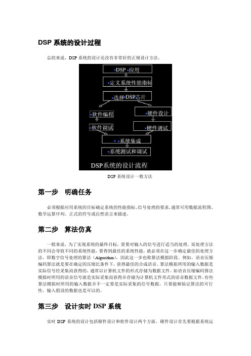
DSP系统的设计过程总的来说,DSP系统的设计还没有非常好的正规设计方法。
DSP系统设计一般方法第一步明确任务必须根据应用系统的目标确定系统的性能指标、信号处理的要求,通常可用数据流程图、数学运算序列、正式的符号或自然语言来描述。
第二步算法仿真一般来说,为了实现系统的最终目标,需要对输入的信号进行适当的处理,而处理方法的不同会导致不同的系统性能,要得到最佳的系统性能,就必须在这一步确定最佳的处理方法,即数字信号处理的算法(Algorithm),因此这一步也称算法模拟阶段。
例如,语音压缩编码算法就是要在确定的压缩比条件下,获得最佳的合成语音。
算法模拟所用的输入数据是实际信号经采集而获得的,通常以计算机文件的形式存储为数据文件。
如语音压缩编码算法模拟时所用的语音信号就是实际采集而获得并存储为计算机文件形式的语音数据文件。
有些算法模拟时所用的输入数据并不一定要是实际采集的信号数据,只要能够验证算法的可行性,输入假设的数据也是可以的。
第三步设计实时DSP系统实时DSP系统的设计包括硬件设计和软件设计两个方面。
硬件设计首先要根据系统运算量的大小、对运算精度的要求、系统成本限制以及体积、功耗等要求选择合适的DSP芯片。
然后设计DSP芯片的外围电路及其他电路。
软件设计和编程主要根据系统要求和所选的DSP芯片编写相应的DSP汇编程序,若系统运算量不大且有高级语言编译器支持,也可用高级语言(如C语言)编程。
由于现有的高级语言编译器的效率还比不上手工编写汇编语言的效率,因此在实际应用系统中常常采用高级语言和汇编语言的混合编程方法,即在算法运算量大的地方,用手工编写的方法编写汇编语言,而运算量不大的地方则采用高级语言。
采用这种方法,既可缩短软件开发的周期,提高程序的可读性和可移植性,又能满足系统实时运算的要求。
DSP硬件和软件设计完成后,就需要进行硬件和软件的调试。
软件的调试一般借助于DSP开发工具,如软件模拟器、DSP开发系统或仿真器等。
关于DSP课程设计指导书

虽说是图片粘贴,但都是心血啊!!!SEED-BLDC模板本章描述SEED-BLDC模板的物理布局,说明各连接器的定义、跳针的设置,以及它们在模板上的位置。
5.1 板子外形和物理尺寸SEED-BLDC 采用两层板工艺,长116.9mm×100.7mm,采用表面贴装元器件,元器件双面安装。
SEED-BLDC 模板正面布局如下图所示:SEED-BLDC 模板反面布局如下图所示:5.2 连接器5.2.1 P3: 三相无刷电机U、V、W图5-3三相无刷电机U、V、W 的输入端SEED-BLDC 上有一个三孔的凤凰端子,为三相直流无刷电机U、V、W 的输入端。
如图5-3。
5.2.2 P4: 有位置传感器的电机的霍尔传感器输出端采用2mm 间距、5-芯单排直插式连接器,与有位置传感器的电机的霍尔传感器输出5.2.3 P5: 模拟部分电源的输入端5.2.4 P6: 电机控制驱动部分接口电机控制驱动部分接口采用 2.54mm 间距、26-芯双排直插式连接器,其引脚定义如下:5.2.5 P8: 无位置传感器电机反电动势输出端5.2.7 P10: 电机的直流母线电压的输入端SEED-BLDC 上有一个两孔的凤凰端子,为三相直流无刷电机直流母线电压的输入端,如图5-4。
图5-4 直流母线电压的输入端5.3 LED指示灯在SEED-BLDC 系统中共有5 个指示灯,分别为D12、D13、D14、D15、D16,SEED-BLDC 系统的测试程序包括一下几个部分:⏹有位置传感器无刷电机的开环控制⏹有位置传感器无刷电机的闭环控制,采用PID 控制⏹无位置传感器无刷电机的开环控制⏹若与实验箱连,与上位机相连的有位置传感器的无刷电机的闭环PID 控制注:测试程序的工程调试环境是以合众达公司的USB 口仿真器建立的,为了方便起见,推荐用户使用合众达公司的USB 口仿真器进行测试。
如果使用其他类型的仿真器,请参考附录创建相应的工程调试环境。
DSP芯片制造工艺流程
DSP芯片制造工艺流程DSP(Digital Signal Processing)芯片是一种专门用于数字信号处理的集成电路芯片。
它可以通过算法来解析、处理和转换数字信号,广泛应用于音频、视频和无线通信等领域。
下面将介绍DSP芯片的制造工艺流程。
首先,DSP芯片的制造工艺流程包括概念设计、前期设计、制造工艺设计、掩膜制作、晶圆加工、封装测试等多个环节。
首先是概念设计阶段。
在这个阶段,芯片设计工程师会根据芯片的功能需求和性能指标进行初步的设计方案制定。
他们会选择适合的处理器核心、内存、接口等组件,并进行电路图设计和模拟仿真以验证设计的可行性。
接下来是前期设计阶段。
在这个阶段,芯片设计工程师会使用专业的EDA(Electronic Design Automation)软件工具进行详细的电路设计和布局。
他们会将电路图转换为物理结构,考虑电路元件的大小、位置和连接方式,以及电源分配和信号路由等。
在此过程中,他们还会进行各种静态和动态的电性能分析和优化。
然后是制造工艺设计阶段。
在这个阶段,芯片制造工程师会根据芯片设计图纸,选择合适的制造工艺流程,并确定各种加工步骤和参数。
这些包括光刻、薄膜沉积、腐蚀、离子注入、扩散、金属化和封装测试等。
随后是掩膜制作阶段。
掩膜是制造芯片的重要工具,它是一种透明薄膜,上面印刷有电路图案。
掩膜制作工程师会根据制造工艺设计的要求,通过光刻技术将电路图案转移到掩膜上。
然后是晶圆加工阶段。
晶圆是制造芯片的基材,它通常是用纯度极高的硅材料制成。
晶圆加工工程师会使用掩膜将电路图案印刷到晶圆表面上,并通过一系列的工艺步骤,将掩膜中的电路图案转移到晶圆上。
这些步骤包括光刻、薄膜沉积、腐蚀、离子注入、扩散、金属化等。
最后是封装测试阶段。
在这个阶段,芯片封装工程师会将晶圆上的芯片切割成单独的芯片,并将其封装到塑料、陶瓷或金属封装中。
接下来进行测试,以确保芯片的功能和性能符合设计要求。
总结起来,DSP芯片的制造工艺流程包括概念设计、前期设计、制造工艺设计、掩膜制作、晶圆加工、封装测试等多个环节。
DSP设计流程

DSP设计流程
引言
世界正处于高科技下一波快速增长的开端,AccelChip 公司Dan Ganousis DSP 已经成为业界公认的、将按指数增长的技术焦点。
目前,大多数DSP 设计已经能在半导体生产商(如T1、ADI、Freescale 等)提供的通用DSP 芯片上实现。
通用处理器的价格相对比较便宜,并且有高质量和廉价的编程工具、方便快速实现DSP 算法的支持,但开发人员更希望在原型创建和调试过程中能进行重新编程。
速度的需要
现在,对电子系统的性能要求已经超过了通用DSP 处理器的能力。
传统上DSP 开发者可以获得的改变通用DSP 处理器性能的唯一方法就是将DSP 算法注入到ASIC 中,以达到加速硬件的目的。
然而这种ASIC 的解决方法实现
起来非常困难,而且在ASIC 上实现DSP 算法是以牺牲可重编程的灵活性为代价的,同时还需要大量的非重复设计费用、漫长的原型初始化,以及购买大量
昂贵的集成电路设计工具等。
随着先进的FPGA 架构如Xilinx Virtex-II 和Altera Stratix-II 的引入,DSP 设计者可以获得一种把通用DSP 处理器的所有优点与ASIC 的先进性能综合在一起的新型硬件。
这些新型的FPGA 架构可以优化DSP 的实现,并能提供满足现今电子系统所必需的处理能力。
FPGA 的优越性表现在它能允许DSP 设计者做到使结构适应算法,设计者能够根据实现系统性能的需要最大限度地使用FPGA 内部的并行资源。
而在通用DSP 处理器中资源是固定的,因为每个处理器只包含一些数量有限的类似乘法器一样的基本运算功能,设计者必须做到使算法适应结构,因而无法达到在。
- 1、下载文档前请自行甄别文档内容的完整性,平台不提供额外的编辑、内容补充、找答案等附加服务。
- 2、"仅部分预览"的文档,不可在线预览部分如存在完整性等问题,可反馈申请退款(可完整预览的文档不适用该条件!)。
- 3、如文档侵犯您的权益,请联系客服反馈,我们会尽快为您处理(人工客服工作时间:9:00-18:30)。
101 Innovation DriveSan Jose, CA 95134 DSP Design FlowUser GuideDocument Date:April 2009Copyright © 2009 Altera Corporation. All rights reserved. Altera, The Programmable Solutions Company, the stylized Altera logo, specific device designations, and all other words and logos that are identified as trademarks and/or service marks are, unless noted otherwise, the trademarks and service marks of Altera Corporation in the U.S. and other countries. All other product or service names are the property of their respective holders. Altera products are protected under numerous U.S. and foreign patents and pending ap-plications, maskwork rights, and copyrights. Altera warrants performance of its semiconductor products to current specifications in accordance with Altera's standard warranty, but reserves the right to make changes to any products and services at any time without notice. Altera assumes no responsibility or liability arising out of the application or use of any information, product, or service described herein except as expressly agreed to in writing by Altera Corporation. Altera customers are advised to obtain the latest version of device specifications before relying on any published information and before placing orders for products or services.UG-10039-3.1© April 2009Altera CorporationDSP Design Flow User Guide ContentsChapter 1.IntroductionDigital Signal Processing . . . . . . . . . . . . . . . . . . . . . . . . . . . . . . . . . . . . . . . . . . . . . . . . . . . . . . . . . . . . . . . . . 1–1FPGA Architecture Features . . . . . . . . . . . . . . . . . . . . . . . . . . . . . . . . . . . . . . . . . . . . . . . . . . . . . . . . . . . . . . 1–1Software Design Flow with DSP Processors . . . . . . . . . . . . . . . . . . . . . . . . . . . . . . . . . . . . . . . . . . . . . . . . . 1–3DSP Design Flow in FPGAs . . . . . . . . . . . . . . . . . . . . . . . . . . . . . . . . . . . . . . . . . . . . . . . . . . . . . . . . . . . . . . . 1–4Software Flow in FPGAs . . . . . . . . . . . . . . . . . . . . . . . . . . . . . . . . . . . . . . . . . . . . . . . . . . . . . . . . . . . . . . . 1–4Software Combined with Hardware Acceleration . . . . . . . . . . . . . . . . . . . . . . . . . . . . . . . . . . . . . . . . . 1–4Hardware Design Flow . . . . . . . . . . . . . . . . . . . . . . . . . . . . . . . . . . . . . . . . . . . . . . . . . . . . . . . . . . . . . . . . 1–5Benefits of FPGAs in DSP Designs . . . . . . . . . . . . . . . . . . . . . . . . . . . . . . . . . . . . . . . . . . . . . . . . . . . . . . . . . 1–5Chapter 2.DSP Design Building BlocksMegaCore Functions . . . . . . . . . . . . . . . . . . . . . . . . . . . . . . . . . . . . . . . . . . . . . . . . . . . . . . . . . . . . . . . . . . . . . 2–1Design Flows . . . . . . . . . . . . . . . . . . . . . . . . . . . . . . . . . . . . . . . . . . . . . . . . . . . . . . . . . . . . . . . . . . . . . . . . . . . 2–2Chapter 3.DSP BuilderDSP Builder Design Flow . . . . . . . . . . . . . . . . . . . . . . . . . . . . . . . . . . . . . . . . . . . . . . . . . . . . . . . . . . . . . . . . . 3–1Standard and Advanced Blocksets . . . . . . . . . . . . . . . . . . . . . . . . . . . . . . . . . . . . . . . . . . . . . . . . . . . . . . . . . 3–1Standard Blockset . . . . . . . . . . . . . . . . . . . . . . . . . . . . . . . . . . . . . . . . . . . . . . . . . . . . . . . . . . . . . . . . . . . . . 3–2Advanced Blockset . . . . . . . . . . . . . . . . . . . . . . . . . . . . . . . . . . . . . . . . . . . . . . . . . . . . . . . . . . . . . . . . . . . . 3–3Installing DSP Builder . . . . . . . . . . . . . . . . . . . . . . . . . . . . . . . . . . . . . . . . . . . . . . . . . . . . . . . . . . . . . . . . . . . 3–3DSP Builder Standard and Advanced Blockset Interoperability . . . . . . . . . . . . . . . . . . . . . . . . . . . . . . . . 3–4Combined Blockset Example . . . . . . . . . . . . . . . . . . . . . . . . . . . . . . . . . . . . . . . . . . . . . . . . . . . . . . . . . . . 3–6Archiving Combined Blockset Designs . . . . . . . . . . . . . . . . . . . . . . . . . . . . . . . . . . . . . . . . . . . . . . . . . . 3–10Tool Integration . . . . . . . . . . . . . . . . . . . . . . . . . . . . . . . . . . . . . . . . . . . . . . . . . . . . . . . . . . . . . . . . . . . . . . . . 3–10Simulink . . . . . . . . . . . . . . . . . . . . . . . . . . . . . . . . . . . . . . . . . . . . . . . . . . . . . . . . . . . . . . . . . . . . . . . . . . . . 3–10ModelSim . . . . . . . . . . . . . . . . . . . . . . . . . . . . . . . . . . . . . . . . . . . . . . . . . . . . . . . . . . . . . . . . . . . . . . . . . . . 3–11Quartus II . . . . . . . . . . . . . . . . . . . . . . . . . . . . . . . . . . . . . . . . . . . . . . . . . . . . . . . . . . . . . . . . . . . . . . . . . . . 3–12SOPC Builder . . . . . . . . . . . . . . . . . . . . . . . . . . . . . . . . . . . . . . . . . . . . . . . . . . . . . . . . . . . . . . . . . . . . . . . 3–12Appendix ing Hardware in the Loop with the DSP Builder Advanced BlocksetCombined Blockset Example . . . . . . . . . . . . . . . . . . . . . . . . . . . . . . . . . . . . . . . . . . . . . . . . . . . . . . . . . . . . . A–1Advanced Blockset Example . . . . . . . . . . . . . . . . . . . . . . . . . . . . . . . . . . . . . . . . . . . . . . . . . . . . . . . . . . . . . A–6Additional InformationRevision History . . . . . . . . . . . . . . . . . . . . . . . . . . . . . . . . . . . . . . . . . . . . . . . . . . . . . . . . . . . . . . . . . . . . . Info–1How to Contact Altera . . . . . . . . . . . . . . . . . . . . . . . . . . . . . . . . . . . . . . . . . . . . . . . . . . . . . . . . . . . . . . . . Info–1Typographic Conventions . . . . . . . . . . . . . . . . . . . . . . . . . . . . . . . . . . . . . . . . . . . . . . . . . . . . . . . . . . . . . Info–1iv Contents DSP Design Flow User Guide© April 2009Altera Corporation© April 2009Altera CorporationDSP Design Flow User Guide 1.IntroductionThis document is an introduction to DSP design for implementation in AlteraFPGAs. using Altera DSP Builder. It introduces the DSP Builder standard andadvanced blockset tools, and the DSP IP libraries that are provided with these tools.Digital Signal ProcessingThe digital signal processing (DSP) market includes rapidly evolving applicationssuch as 3G Wireless, voice over Internet protocol (VoIP), multimedia systems, radarand satellite systems, medical systems, image-processing applications, and consumerelectronics. These applications cover a broad spectrum of performance and costrequirements.Specialized DSP processors are used for implementing many of these applications.Although these DSP processors are programmable through software, their hardwarearchitecture is not flexible. Therefore, DSP processors are limited by fixed hardwarearchitecture such as bus performance bottlenecks, a fixed number of multiplyaccumulate (MAC) blocks, fixed memory, fixed hardware accelerator blocks, andfixed data widths. The DSP processor’s fixed hardware architecture is not suitable forcertain applications that might require customized DSP function implementations.FPGAs provide a reconfigurable solution for implementing DSP applications as wellas higher DSP throughput and raw data processing power than DSP processors.Because FPGAs can be reconfigured in hardware, they offer complete hardwarecustomization while implementing various DSP applications. Therefore, DSP systemsimplemented in FPGAs can have customized architecture, customized bus structure,customized memory, customized hardware accelerator blocks, and a variable numberof MAC blocks.FPGA Architecture FeaturesFPGA devices consist of logic elements (LEs) and memory that can be configured tooperate in different modes corresponding to a required functionality. This hardwareflexibility allows a you to implement any hardware design described using a suitablehardware description language (HDL) such as VHDL or Verilog HDL. Thus, the sameFPGA can implement a DSL router, a DSL modem, a JPEG encoder, a digital broadcastsystem, or a backplane switch fabric interface.High-density FPGAs, such as Altera’s Stratix ® families, incorporate embedded siliconfeatures that can implement complete systems inside an FPGA, creating a system on aprogrammable chip (SOPC) implementation. Embedded silicon features such asembedded memory, DSP blocks, and embedded processors are ideally suited forimplementing DSP functions such as finite impulse response (FIR) filters, fast Fouriertransforms (FFTs), correlators, equalizers, encoders, and decoders.FPGA Architecture FeaturesDSP Design Flow User Guide © April 2009Altera Corporation The embedded DSP blocks also provide other functionality such as accumulation,addition/subtraction, and summation that are common arithmetic operations in DSPfunctions. For example, Stratix device DSP blocks offer up to 224 multipliers that canperform 224 multiplications in a single clock cycle. Compared to DSP processors thatonly offer a limited number of multipliers, Altera FPGAs offer much more multiplierbandwidth.One determining factor of the overall DSP bandwidth is the multiplier bandwidth,therefore the overall DSP bandwidth of FPGAs can be much higher using FPGAs thanwith a DSP processors. For example, Stratix device DSP blocks can deliver 70 GMACSof DSP throughput while typical DSP processors available can deliver only up to 4.8GMACS. Figure 1–2 highlights the DSP-related features available in Altera FPGAdevice families.Many DSP applications use external memory devices to manage large amounts ofdata processing. The embedded memory in FPGAs meets these requirements and alsoeliminates the need for external memory devices in certain cases. For example, theStratix device family offers up to 10 Mbits of embedded memory through theTriMatrix TM memory feature.Embedded processors in FPGAs provide overall system integration and flexibilitywhile partitioning the system between hardware and software. You can implementthe system’s software components in the embedded processors and implement thehardware components in the FPGA's general logic resources. Altera devices provide achoice between embedded soft core processors and embedded hard core processors.You can implement soft core processors such as the Nios ® II embedded processor inFPGAs and add multiple system peripherals. The Nios II processor supports auser-determinable multi-master bus architecture that optimizes the bus bandwidthand removes potential bottlenecks found in DSP processors. You can use multi-masterbuses to define as many buses and as much performance as needed for a particularapplication. Off-the-shelf DSP processors make compromises between size andperformance when they choose the number of data buses on the chip, potentiallylimiting performance.Figure 1–1.DSP Related Features in Altera FPGA DevicesEmbedded HardMicroprocessor CoresNios â Embedded Soft Micorprocessor CoresI/O StandardsHigh Speed I/OInterface Embedded DSP BlocksEmbedded MemoryEmbedded Multipliers External MemoryInterfacesSoftware Design Flow with DSP ProcessorsSoft embedded processors in FPGAs provide access to custom instructions such as theMUL instruction in Nios II processors that can perform a multiplication operation intwo clock cycles using hardware multipliers. FPGA devices provide a flexibleplatform to accelerate performance-critical functions in hardware because of theconfigurability of the device’s logic resources. Unlike DSP processors that havepredefined hardware accelerator blocks, FPGAs can implement hardware acceleratorsfor each application, allowing the best achievable performance from hardwareacceleration. You can implement hardware accelerator blocks by designing suchblocks using parameterizable IP functions or from scratch using HDL.Altera offers the MegaCore® functions for DSP design that support error detectionand correction (Reed Solomon and Viterbi), filters (CIC and FIR), signal generation(NCO), transforms (FFT) and video and image processing (Alpha Blending Mixer,Chroma Resampler, Clipper, Clocked Video Input, Clocked Video Output, ColorPlane Sequencer, Deinterlacer, 2D FIR Filter, 2D Median Filter, Frame Buffer, GammaCorrector, Line Buffer Compiler, Scaler).For more information about these MegaCore functions, refer to Chapter2, DSPDesign Building Blocks.Each of these functions can be parameterized (using the MegaWizard™ interface) todesign the most efficient hardware implementation for a given set of parameters. Thisprovides maximum flexibility, allowing you to customize IP without changing adesign's source code. You can integrate a parameterized IP core in any hardwaredescription language (HDL) or netlist file generated using any EDA tool. You caneasily port the IP to new FPGA families, leading to higher performance and lowercost. The flexibility of programmable logic and soft IP cores allows you to quicklyadapt your designs to new standards without waiting for long lead times usuallyassociated with DSP processors.Software Design Flow with DSP ProcessorsFigure1–2 shows the typical software design flow that DSP programmers follow.Figure1–2.Software-Based DSP Design Flow© April 2009Altera Corporation DSP Design Flow User GuideDSP Design Flow in FPGAs Algorithm development tools such as MATLAB are often used to optimize DSPalgorithms and Simulink for system-level modeling. The algorithms and thesystem-level models are then implemented in C/C++ or Assembly code using anintegrated development environment, that provides design, simulation, debug, andreal-time verification tools. You can use standard C-based DSP libraries to shortendesign cycles and derive the benefits of design re-use.DSP Design Flow in FPGAsTraditionally, DSP systems were implemented in FPGAs using the hardware flowbased on a HDL language such as Verilog HDL and VHDL. Altera DSP tools such asDSP Builder, SOPC Builder, and a complete software development platform nowenable you to follow a software-based design flow while targeting FPGAs.Figure1–3 outlines the various design-flow options available for FPGAs.Figure1–3.FPGA-Based DSP Design Flow OptionsSoftware Flow in FPGAsAltera FPGAs with embedded processors support a software-based design flow.Altera provides software development tools for compiling, debugging, assemblingand linking software designs. These software designs can then be downloaded to anFPGA using either on-chip RAM or an external memory device.Software Combined with Hardware AccelerationEmbedded processors and hardware acceleration offer the flexibility, performance,and cost effectiveness in a development flow that is familiar to software developers.You can combine a software design flow along with hardware acceleration. In thisflow, you first profile C code and identify the functions that are the mostperformance-intensive. Then, you can use Altera's DSP IP or develop your owncustom instructions to accelerate those tasks in the FPGA.DSP Design Flow User Guide© April 2009Altera CorporationBenefits of FPGAs in DSP DesignsThe system control code along with the other low-performance DSP algorithms can berun on a Nios II embedded processor.Altera also provides system-level tools such as SOPC Builder for system-levelpartitioning and integration. You can use SOPC Builder to build entire hardwaresystems by combining the embedded processor, such as a Nios II embeddedprocessor, system peripherals, as well as IP MegaCore functions.Altera's DSP Builder tool provides an interface from Simulink directly to the FPGAhardware (Figure1–4). The DSP Builder tool simplifies hardware implementation ofDSP functions, provides a system-level verification tool to the system engineer who isnot necessarily familiar with HDL design flow, and allows the system engineer toimplement DSP functions in FPGAs without learning HDL. Additionally, you canincorporate the designs created by DSP Builder into a SOPC Builder system for acomplete DSP system implementation.Figure1–4.DSP Builder Design Flow for Altera FPGAsHardware Design FlowYou can also develop a pure hardware implementation of a DSP system using aHDL-based design flow. Altera provides a complete set of FPGA development toolsincluding the Quartus® II software and interfaces to other EDA tools such asSynopsys, Synplify, and Precision Synthesis. These tools enable hardware design,simulation, debug, and in-system verification of the DSP system. The suite ofpre-optimized DSP MegaCore functions can simplify this development process. Youcan also follow the DSP Builder design flow shown in Figure1–4 and implementhardware-only DSP systems in FPGAs without learning HDL.Benefits of FPGAs in DSP DesignsFPGA devices provide a reconfigurable DSP solution for various DSP applications.FPGA devices incorporate a variety of embedded features such as embeddedprocessors, DSP blocks, and memory blocks. These device features provide very highDSP capability in FPGAs compared to DSP processors. Using FPGAs, you cancustomize their hardware for optimal implementation of their applications.© April 2009Altera Corporation DSP Design Flow User GuideBenefits of FPGAs in DSP Designs Using embedded processors such as the Nios II embedded processor, FPGAs alsooffer a software-based design flow similar to the traditional DSP software design flow.In addition, FPGAs offer a design flow using SOPC Builder that enables a softwaredesign flow to be combined with hardware acceleration. Using this design flow, youcan implement a complete DSP system in an FPGA and thereby develop acost-effective, high-performance DSP system.Altera FPGAs also offer a design flow based on the DSP Builder tool that allows a DSPsystem engineer designing in MATLAB/Simulink to implement a system on an FPGAwithout learning HDL. The DSP Builder tool flow can also be combined with theSOPC Builder tool flow for implementing a complete DSP system.Hence FPGAs from Altera provide the benefits of system integration, flexibility whilepartitioning the system, lower system costs, and higher performance when comparedto pure DSP processor based implementations.For information about the DSP Builder design flow, refer to Chapter3, DSP Builder.f For information about the SOPC Builder design flow, refer to Volume 4: SOPC Builderof the Quartus II Handbook.DSP Design Flow User Guide© April 2009Altera Corporation© April 2009Altera CorporationDSP Design Flow User Guide 2.DSP Design Building BlocksMegaCore FunctionsThe Altera MegaCore IP library includes the following MegaCore functions that canbe used for DSP design:■Error Detection and Correction■The Reed-Solomon (RS) Compiler implements a fully parameterizable encoderand decoder for forward error correction applications. RS codes are widelyused for error detection and correction in a wide range of DSP applications forstorage, retrieval, and transmission of data.fFor more information, refer to the Reed-Solomon Compiler User Guide .■The Viterbi Compiler implements high-performance, soft-decision ViterbiMegaCore functions that implement a wide range of standard Viterbi decoders.Viterbi decoding (also known as maximum likelihood decoding or forwarddynamic programming) is the most common way of decoding convolutionalcodes by using an asymptotically optimum decoding technique. In its basicform, Viterbi decoding is an efficient, recursive algorithm that performs anoptimal exhaustive search.fFor more information, refer to the Viterbi Compiler User Guide .■Filters■Cascaded integrator-comb (CIC) filters, also known as Hogenauer filters, arecomputationally efficient for extracting baseband signals from narrow bandsources using decimation, and for constructing narrow-band signals fromprocessed baseband signals using interpolation. CIC filters use only addersand registers, and require no multipliers to handle large rate changes.Therefore, CIC is a suitable and economical filter architecture for hardwareimplementation, and is widely used in sample rate conversion designs such asdigital down converters (DDC) and digital up converters (DUC).fFor more information, refer to the CIC MegaCore Function User Guide .■The FIR Compiler provides a fully integrated finite impulse response (FIR)filter development environment. You can use the FIR Compiler to implement avariety of filter architectures, including fully parallel, serial, or multibit serialdistributed arithmetic, and multicycle fixed/variable filters. The FIR Compilerincludes a coefficient generator.fFor more information, refer to the FIR Compiler User Guide .2–2Chapter 2:DSP Design Building BlocksDesign FlowsDSP Design Flow User Guide © April 2009Altera Corporation■Signal Generation■The NCO MegaCore function generates numerically controlled oscillators(NCOs) customized for Altera devices. You can implement a variety ofarchitectures, including ROM-based, CORDIC-based, and multiplier-basedNCOs.fFor more information, refer to the NCO MegaCore Function User Guide .■Transforms■The FFT MegaCore function is a high performance, highly parameterizable fastFourier transform (FFT) processor. The FFT MegaCore function implements acomplex FFT or inverse FFT (IFFT) for high-performance applications using afixed transform size or variable streaming architecture.fFor more information, refer to the FFT MegaCore Function User Guide .■Video and Image Processing■The Video and Image Processing Suite is a collection of MegaCore functionsthat facilitate the development of video and image processing designs. TheMegaCore functions are suitable for use in a wide variety of image processingand display applications and include:Alpha Blending Mixer, Chroma Resampler, Clipper, Clocked Video Input,Clocked Video Output, Color Plane Sequencer, Deinterlacer, 2D FIR Filter, 2DMedian Filter, Frame Buffer, Gamma Corrector, Line Buffer Compiler, Scaler,Clipper, Test Pattern Generator.f For more information, refer to the Video and Image Processing Suite UserGuide .Design FlowsAltera DSP IP MegaCore ® functions can be used in several design flows:■The MegaWizard™ Plug-In Manager can be used with any of the DSP IPMegaCore functions when you want to create a MegaCore function variation thatyou can instantiate manually in your design.■The CIC, FFT, FIR, NCO, Reed-Solomon, and Viterbi MegaCore functions can beincluded as a block in a DSP Builder design. If required, the DSP Builder designcan then be instantiated in a SOPC Builder system.■The Video and Image Processing Suite MegaCore functions can be instantiateddirectly in a SOPC Builder system.f For more information about using MegaCore functions in these design flows, refer tothe appropriate MegaCore function user guide.© April 2009Altera CorporationDSP Design Flow User Guide 3.DSP BuilderDSP Builder Design FlowDSP Builder shortens DSP design cycles by helping you create the hardwarerepresentation of a DSP design in an algorithm-friendly development environment.DSP Builder integrates the algorithm development, simulation, and verificationcapabilities of The MathWorks MATLAB ® and Simulink ® system-level design toolswith the Altera Quartus II software and third-party synthesis and simulation tools.You can combine Simulink blocks with DSP Builder blocks and IP blocks to verifysystem level specifications and perform simulation (Figure 3–1).Standard and Advanced BlocksetsWhen you install DSP Builder two separate blocksets (Altera DSP Builder Blocksetand Altera DSP Builder Advanced Blockset) are added to the Simulink librarybrowser and can be used separately or together.The standard DSP Builder blockset includes libraries of design building and interfaceblocks and a library of blocks that represent each of the DSP MegaCore functions.The advanced DSP Builder blockset does not interface directly with the DSPMegaCore functions but instead includes its own timing-driven IP blocks that can beused to generate high performance FIR, CIC, NCO, and FFT models.Table 3–1 on page 3–2 summarizes the key features of the standard and advancedblocksets.Figure 3–1.DSP Builder Design FlowStandard and Advanced BlocksetsTable3–1.Key Features of the Standard and Advanced BlocksetsBlockset Key FeaturesStandard Blockset Cycle accurate behavioral modelsMultiple clock domain managementControl rich with backpressure supportAccess to specific hardware device featuresHardware-in-the-loop support enables FPGA hardware cosimulationHDL import of VHDL or Verilog HDL design entitiesTabular and graphical state machine supportRapid prototyping using Altera DSP development boardsSignalTap II debug facilitiesDSP MegaCore function variations can be directly instantiatedAdvanced Blockset Specification driven design with automatic pipelining and foldingHigh level synthesis technologyHigh performance timing-driven IP modelsMultichannel designs with automatically vectorized inputsAutomatic generation of memory-mapped interfacesUses Simulink fixed-point typesSingle system clock for the main data path logicFeed forward data path with minimum controlPortability across different device familiesHigh level resource trade-offs such as hard versus soft multipliersYou can use both blocksets in subsystems of the same design when you want tocombine features from each blockset. For example, when you want to combine an IPmodel from the advanced blockset with development board support or hardware-in-the-loop from the standard blockset.Standard BlocksetYou can use blocks from the standard blockset to create a hardware implementationof a system modeled in Simulink in sampled time. DSP Builder contains bit- andcycle-accurate Simulink blocks—which cover basic operations such as arithmetic orstorage functions—and takes advantage of key device features such as built-in PLLs,DSP blocks, or embedded memory.You can integrate complex functions by including MegaCore functions in your DSPBuilder model. You can also use the faster performance and richer instrumentation ofhardware co-simulation by implementing parts of your design in an FPGA.The standard blockset supports imported HDL subsystems including HDL defined ina Quartus II project file.f For more information about the advanced blockset, refer to the DSP Builder ReferenceManual and the DSP Builder User Guide.DSP Design Flow User Guide© April 2009Altera CorporationInstalling DSP Builder © April 2009Altera Corporation DSP Design Flow User Guide Advanced BlocksetThe DSP Builder Advanced Blockset consists of a number of Simulink libraries thatallow you to implement DSP designs quickly and easily. The blockset is based on ahigh level synthesis technology that optimizes the high level, untimed netlist into lowlevel, pipelined hardware targeted to your chosen FPGA device and chosen clockrate. The hardware is written out as VHDL, along with scripts that integrate with theQuartus II software and the Model Sim ® simulator.The combinations of these features allows you to create a design without needingintimate device knowledge, and then generate a high quality implementation thatruns on a variety of FPGA families with different hardware architectures.After specifying your desired clock frequency, number of channels and othertop-level design constraints, the generated RTL is automatically pipelined to achievetiming closure. By analyzing the system-level constraints, the tool also optimizesfolding (that is, time division multiplexing) to achieve optimum logic utilization, withno need for manual RTL editing.The synthesis technology also allows you to easily increase or decrease the number ofchannels—for example, in your FIR filter or digital up conversion signal chain—simply by using a parameter file within the Simulink design. DSP Builder adds therequired time-division multiplexing control logic and generates the updated RTL in amatter of minutes.The advanced blockset includes a library of basic control blocks and two componentlibraries - ModelIP and ModelPrim. These are useful in the following circumstances:■ModelIP: The ModelIP library consists of a set of multichannel, multirate cycle-accurate filters, mixers and a numerically controlled oscillator (NCO) that allowyou to quickly create designs for digital front end applications. Severalimplementation examples including up and down converters are provided.■ModelPrim: The ModelPrim library allows you to create fast efficient designscaptured in the behavioral domain rather than the implementation domain bycombining zero latency primitive blocks. For example, you can use a delay blockand let the tool decide how to implement that delay.The advanced blockset is particularly suited for streaming algorithms characterizedby continuous data streams and occasional control. (For example, RF card designsthat comprise long filter chains.)f For more information about the advanced blockset, refer to the DSP Builder AdvancedBlockset Reference Manual and the DSP Builder Advanced Blockset User Guide .Installing DSP BuilderDSP Builder can be installed by selecting an option in the install program for theQuartus II software. The installer allows you to install either or both blocksets.f For more information, refer to the DSP Builder Installation and Licensing manual.。
