FR02FC10P-S中文资料
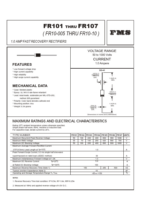
FR10-10中文资料
.01
.6
.8
1.0
1.2
1.4
1.6
1.8
2.0
FORWARD VOLT AGE,(V)
24
FIG.3- TEST CIRCUIT DIAGRAM AND REVERSE RECOVERY TIME CHARACTERISTICS
50W NONINDUCTIVE 10W NONINDUCTIVE
.034(.9) .028(.7) DIA. .205(5.2) .166(4.2)
1.0(25.4) MIN.
Dimensions in inches and (millimeters)
MAXIMUM RATINGS AND ELECTRICAL CHARACTERISTICS
Rating 25 C ambient temperature uniess otherwies specified. Single phase half wave, 60Hz, resistive or inductive load. For capacitive load, derate current by 20%.
TYPE NUMBER
Maximum Recurrent Peak Reverse Voltage Maximum RMS Voltage Maximum DC Blocking Voltage Maximum Average Forward Rectified Current .375"(9.5mm) Lead Length at Ta=75 C Peak Forward Surge Current, 8.3 ms single half sine-wave superimposed on rated load (JEDEC method) Maximum Instantaneous Forward Voltage at 1.0A Maximum DC Reverse Current Ta=25 C at Rated DC Blocking Voltage Ta=100 C Maximum Reverse Recovery Time (Note 1) Typical Junction Capacitance (Note 2) Operating and Storage Temperature RaTj=25 C 8.3ms Single Half Sine Wave JEDEC method
FR10M中文资料

MCC
Features
• • • •
omponents 21201 Itasca Street Chatsworth !"# $
% !"#
元器件交易网
MCC
FR10A thru FR10M
Figure 1 Typical Forward Characteristics 20 10 6 4 2 Amps 1 .6 .4 .2 .1 .06 .04 .02 .01 .8 1.0 1.2 Volts Instantaneous Forward Current - Amperes versus Instantaneous Forward Voltage - Volts 1.4 1.6 1.8 0 Amps 12 10 25° C 8 6 4 2 Figure 2 Forward Derating Curve
Single Phase, Half Wave 60Hz Resistive or Inductive Load 0 50 75 100 ° C 125 150 175
Figure 3 Junction Capacitance 100 60 40 20 pF 10 6 4 2 1 .1 .2 .4 1 Volts 2 4 10 20 40 100 200 400 1000 T J =25° C
-1.0 1cm Set Time Base for 20/100ns/cm
• Operating Temperature: -55° to +150° C C • Storage Temperature: -55° to +150° C C MCC Part Number FR10A FR10B FR10D FR10G FR10J FR10K FR10M Maximum Recurrent Peak Reverse Voltage 50V 100V 200V 400V 600V 800V 1000V Maximum RMS Voltage 35V 70V 140V 280V 420V 560V 700V Maximum DC Blocking Voltage 50V 100V 200V 400V 600V 800V 1000V
FR01AR10PB-S中文资料
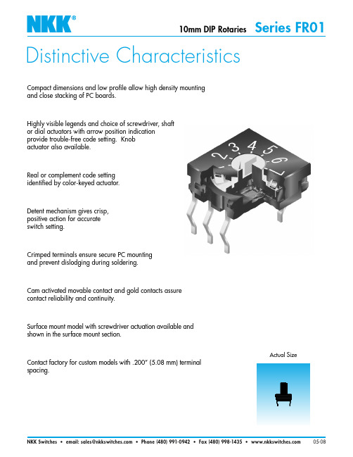
Distinctive CharacteristicsActual SizeCompact dimensions and low profile allow high density mounting and close stacking of PC boards.Highly visible legends and choice of screwdriver, shaft or dial actuators with arrow position indication provide trouble-free code setting. Knob actuator also available.Real or complement code setting identified by color-keyed actuator.Detent mechanism gives crisp, positive action for accurate switch setting.Crimped terminals ensure secure PC mounting and prevent dislodging during soldering.Cam activated movable contact and gold contacts assure contact reliability and continuity.Surface mount model with screwdriver actuation available and shown in the surface mount section.Contact factory for custom models with .200” (5.08 mm) terminal spacing.General SpecificationsElectrical Capacity (Resistive Load)Switching Rating:100mA @ 5V DCNonswitching Rating:100mA @ 50V DCOther RatingsContact Resistance:100 milliohms maximum for circuit; 30 milliohms maximum for contact pointInsulation Resistance: 1,000 megohms minimum @ 250V DCDielectric Strength: 250V AC minimum for 1 minute minimumMechanical Life: 10,000 detent operations minimumElectrical Life: 10,000 detent operations minimumNotes: A detent operation is one actuator position operation or stepping.A cycle is one 360° rotation. 10,000 detent operations equal 625cycles for hexadecimal devices or 1,000 cycles for decimal devices.Nominal Operating Torque:Metal Shaft: 0.009Nm for decimal devices; 0.011Nm for hexadecimal devicesAll other Actuator types: 0.008Nm for decimal devices; 0.01Nm for hexadecimal devices Contact Timing:Shorting (Avoid possible false signal by turning off power before switching.)Materials & FinishesActuators: Screwdriver and Plastic Shaft - Glass fiber reinforced polyamide (UL94V-0);Dial - Polyoxymethylene; Metal Shaft - Brass with nickel platingBushing : Brass with nickel plating (for Metal Shaft model)Outer Case: Glass fiber reinforced PBT (for Metal Shaft model)Housing & Base: Glass fiber reinforced polyamide (UL94V-0)Movable Contacts: Copper alloy with gold platingStationary Contacts: Phosphor bronze with gold platingTerminals: Phosphor bronze with gold platingTerminal Cover: Polyamide (Right angle model only)Bracket: Phospher bronze with tin plating (for Metal Shaft model)Environmental DataOperating Temperature Range: –25°C through +85°C (–13°F through +185°F)Humidity:90 ~ 95% humidity for 240 hours @ 40°C (104°F)Vibration: 10 ~ 55Hz with peak-to-peak amplitude of 1.5mm traversing the frequency range & returningin 5 minutes; 3 right angled directions for 2 hoursShock: 50G (490m/s2) acceleration (tested in 6 right angled directions, with 5 shocks in each direction)PCB ProcessingSoldering: Wave Soldering Recommended. See Profile A in Supplement section.Manual Soldering: See Profile A in Supplement section.Cleaning:These devices are not process sealed. Hand clean locally using alcohol based solution.Custom process sealed version available; contact factory.Standards & CertificationsFlammability Standards:UL94V-0 rated actuator, housing and baseUL Recognition The FR01 Series rotaries have not been tested for UL recognition or CSA certification.or CSA Certification:These switches are designed for use in a low-voltage, low-current circuit.When used as intended, the results do not produce hazardous energy.TYPICAL SWITCH ORDERING EXAMPLEFScrewdriverACTUATIONAdjusted with a flat tipped screwdriverInstall knob before mounting on PCB for right angle type; it should not be removed once mounted. When mounting, align slit in knob with arrowhead on actuator.Polyamide Black knob with transparent flangeAT4180Actuators are fully rotational either clockwise or counterclockwise.Actuator Colors: Orange for real coded devices; Yellow for complement coded devices.01Through-holeMOUNTINGDESCRIPTION FOR TYPICAL ORDERING EXAMPLEFR01KR16P-SHexadecimal PositionsReal CodedStraight PC TerminalsPlastic ShaftPackaged in Stick-TubeOPTIONAL KNOBS FOR METAL SHAFTPolyester Base:BlackPolyamide TipColors:A, B, C, E, F, G, HMaterial:PolyacetalColor:BlackPolyester Base:BlackPolyamide TipColors:A, B, C, E, F, G, HAT4103 SmallColor TippedAT4104 LargeColor TippedAT433Plain BlackAMetal ShaftKnob optionsillustrated belowwith color choicesActuators are fully rotational and operate either clockwise or counterclockwise.Colors for Actuators K and S: Orange for real coded devices; Yellow for complement coded devicesACTUATIONKPlastic ShaftAdjusted by handor with flat tippedscrewdriverSDialAdjusted by handor with flat tippedscrewdriverTerminal numbers are actually on the switch.Above sequence shown for clockwise rotation.Color Codes: A Black B White C Red E Yellow F Green G Blue H GrayMounting hardware is available if needed for models with Actuator A:Hexagon Nut AT513M, Locking Ring AT515M, and Lockwasher AT509; all are shown in the Accessories and Hardware section.Knob Orientation: When installed with shaft flat rotated 180° from bushing flat as shown in “Typical Switch Dimensions,”white line on cap points to Actuator Position 0 noted in truth tables below.FR01FC10PFR01FR10HCDecimal HexadecimalDecimal HexadecimalPRight Angle PC • ScrewdriverHRight Angle PC • Plastic ShaftStraight PC • Plastic ShaftFR01KR16PFR01KC16HC.100CDecimal HexadecimalDecimal HexadecimalPHStraight PC • ScrewdriverFR01SR10P FR01AR10PB Shown in Position 0 with shaft flat rotated 180° from bushing flatStraight PC • DialPStraight PC • Metal ShaftPRight Angle PC • Metal ShaftFR01AC16HB Shown in Position 0 with shaft flat rotated 180° from bushing flatHDecimalHexadecimalC.090.100PACKAGINGFR01F with Screwdriver Actuation & Straight PC FR01F , FR01K & FR01SEach stick-tube contains 50 switches.Switches must be ordered in 50-piece increments.FR01AEach stick-tube contains 25 switches.Switches must be ordered in 25-piece increments.Note: Transport and storage temperatures should not exceed 50°C (122°F). Store stick tubes on flat surface.SStick-TubeFR01K with Plastic Shaft & Right Angle PCFR01S with Dial Actuation & Straight PCFR01A with Metal Shaft & Straight PCFR01A with Metal Shaft & Right Angle PC。
IR2010SPBF中文资料
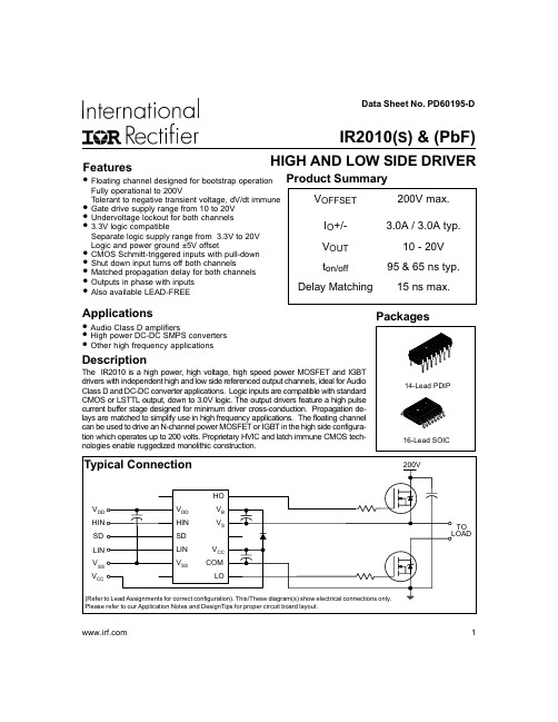
Packages
14-Lead PDIP 16-Lead SOIC
Typical Connection
200V
HO
VDD
VDD
VB
HIN
HIN
VS
SD
SD
LIN
LIN
VCC
VSS
VSS
COM
VCC
LO
(Refer to Lead Assignments for correct configuration). This/These diagram(s) show electrical connections only. Please refer to our Application Notes and DesignTips for proper circuit board layout.
元器件交易网
Data Sheet No. PD60195-D
IR2010(S) & (PbF)
Features
HIGH AND LOW SIDE DRIVER
• Floating channel designed for bootstrap operation Product Summary
Package power dissipation @ TA ≤ +25°C (14 lead DIP) (16 lead SOIC)
Thermal resistance, junction to ambient
(14 lead DIP)
(16 lead SOIC)
Junction temperature
Symbol
VB VS VHO VCC VLO VDD VSS VIN dVs/dt PD
富士通用变频器 FRNFSC

以往变频器的节能功能,是根据负载状态将电动机单体的损耗降低到最小。
新开发的FRENIC-VP系列更新了着眼点,将变频器自身也作为电器产品之一考虑。
不仅将电动机的损耗降低到最小,同时也将变频器的耗电量控制到最低程度(最适合最小耗电量控制)。
由此,节能效果再次提高数个百分比。
2005年2月16日《京都协定》正式生效,这也是中国政府和中国企业不可回避的责任,达到行业最高水准的高效节能FRENIC-VP系列则是您最好的选择。
使用变频器的操作面板,可以随时确认有关电力的数据。
可监控项目功率消耗(kW)累计功率消耗(kWh)累计消耗电费(元/kWh)※累计数值可以复原。
选择累计消耗电费表示时,需要事先设定1kWh的电费单价,可以选择外国的货币单位。
●右表中列出了风机/泵类设备在依靠节气闸(阀门)/变频器控制进行运转时,风量/流量和用电量之间的对应关系计算式。
另列举了在变频器控制时,电源频率fs(Hz)和变频器频率fINV(Hz)之间的计算关系式。
●可见,风量/流量越小节能效果越显着。
■使用变频器的节能效果计算方式(公式)3相200V系列(*1) 标准适用电动机指富士电机公司的4极标准电动机。
(*2) 额定容量显示为200V系列:220V额定/400V系列:440V额定两种。
(*3) 不能输出高于电源的电压。
(*4) 载频设定过低时,电动机的温度会大幅上升,有可能启动变频器的保护功能(限制输出电流)。
载频值在1kHz以下运行时,请将选用的变频器的额定输出电流值设定为实际输出电流值的80%。
(*5) 电源容量是500KVA(变频器容量超过50KVA时,是变频容量的十倍)在连接到%X=5%的电源时的计算值。
(*6) 使用直流电抗器(DCR)时适用的值。
(*7) 电动机本体平均制动转矩的数值。
(随电动机的效率变化。
)(*8) 相间不平衡率[%] = ( 最大电压[V]-最小电压[V] )/3相平均电压(V)×67(根据IEC61800-3)相间不平衡率为2~3%时,请使用交流电抗器(ACR选配件)(*9) 和附带电源再生功能的PWM换流器组合使用时,作为AC风扇的电源输入使用。
塑壳断路器1

10KA
D3 C45N
结论: 级联技术可以使得分断能力大大低于其安 装处预期短路电流的断路器可以在正常分断的条 件下运行.
施耐德电器公司-ABT产品培训教材-ZXF
23
E37960
Compact NS
有选择性的级联
Compact NS 的配合
无选择性的级联
I B
I A 5 0 k A
A
BP B
P A
Compact 系列产品
一般特性
KA
160
150
150
150
140
120
100
80
70
70
70
70
70
60
50
45
40 36
25
20
0
NS80
NS100 NS160/250 NS400/630 NS800/1250
施耐德电器公司-ABT产品培训教材-ZXF
E37951
=N =H =L
9
Compact NS
15 5/1 15 5/1 15 5/1 15 5/1 15 5/1155/1 15 5/1155/11 55/1155/1155/11 55/1 15 5/1155/1 15 5/1 25 0/2 2
15 5/1 15 5/1 15 5/1 15 5/1 15 5/1155/1 15 5/1155/11 55/1155/1155/11 55/1 15 5/1155/1 25 0/20/2 2
在承受门限电流的电动力之后:能量选择性
17
Compact NS
选择性
新系列
产品:
工具:
1 个标准的脱扣器
1 个简单的原则。
FC202系列标准负载变频器

持续 间歇/60秒
输 出容量 ( 2 0 8 V)
持续
最 大电缆横截面 ( 输入电源端, 电机输出端, 制动电阻端 )
最 大输入电流
持续 间歇/60秒
最 大外接输入快 熔(主电源)
环境 额 定最大负载时 的预计功率损 耗
重量 IP20
IP21
I P5 5 ,I P66
效率
[kW] [H P] [A] [A]
50℃运行环境温度
变 频器能在高达50℃的环境温度下达 到 最大的输出 ,在 最大55℃的环境 温 度下仍可降容运行。
VLT®FC202本 地控 制面板20 04年获 得 国际iF设计奖 ,在“界面 通讯” 类 来自34个国 家的1000项产 品中一 举夺魁。
直流电抗器
内置直流电抗器,有效降低电源的谐 波 干 扰 , 符 合 IEC-1000-3-2国 际标 准。设计紧凑、无需外部选件。
13 防腐蚀
具 有防腐蚀性的背 部散热通道组件 和 散 热片可以作为选 件订购,用于一 些 恶 劣的环境,例如 靠近海边的含盐 空 气中。
14 控制端子
专 门开发的笼式弹 簧夹紧端子增强 了 可靠性,而且便于调试和维护。
外壳封装
变 频器外壳封装符 合保 护等级IP20, 另 有 IP00, IP21, IP54, IP55和 IP66多种封装等级可选。
FC202系列 标准负载变频器
模 块 式V L T ®FC 2 0 2变 频 器
——使风机、水泵、以及轻过载型通用机械的控制省心省力、得心应手
用于泵和风机
在任 何工 业的泵 、风 机等 变转矩 应用
中, VLT®FC202系列变频器 都能 取得
较高 的传 动质量 和显 著的 节能效 果。
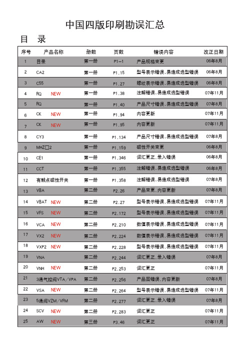
中文四版-SMC样本
2.5, 4
CAT.C06-02A
6, 10, 15
CAT.C06-02A
6, 10, 16
CAT.C04-01A
错误内容 产品规格变更
改正日期 06年8月
型号表示错误,易造成选型错误 06年8月
螺纹表示错误,易造成选型错误 06年8月
注解错误,易造成选型错误
07年11月
产品尺寸错误,易造成选型错误 07年8月
内容更新
07年11月
内容更新
07年11月
产品尺寸错误,易造成选型错误 磁性开关变更 词汇更正、录入错误
CAT.ES20-152B CAT.ES20-177A CAT.E256A CAT.ES20-179B CAT.E216B CAT.ES20-95B CAT.ES20-157B P-1991-6 CAT.ES20-160A CAT.E204A CAT.ES20-159A CAT.ES20-159A CAT.ES20-159A CAT.ES20-147A
9
f
B1
h+
□C
ZZ + + 行程
□B
A KF N H
S + 行程 ZZ + 行程
N M
(mm)
缸径 行程范围 (mm)
A AL □B B1 □C D E F G H1
J
(mm) 无防护套 带防护套
无防护套
带防护套
K KA M MM N P S
H ZZ e f h
施瓦特PG02抗冲击电阻式电丝箱说明书
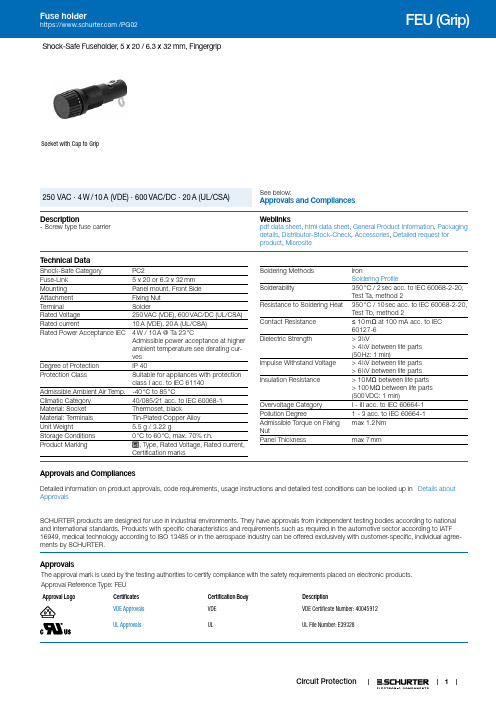
Shock-Safe Fuseholder, 5 x 20 / 6.3 x 32 mm, FingergripSocket with Cap to GripSee below:Approvals and Compliances 250 VAC · 4 W / 10 A (VDE) · 600 VAC/DC · 20 A (UL/CSA)Description- Screw type fuse carrier Weblinkspdf data sheet, html data sheet, General Product Information, Packaging details, Distributor-Stock-Check, Accessories, Detailed request for product, MicrositeT echnical DataShock-Safe Category PC2Fuse-Link 5 x 20 or 6.3 x 32 mmMounting Panel mount, Front SideAttachment Fixing NutTerminal SolderRated Voltage250 VAC (VDE), 600 VAC/DC (UL/CSA) Rated current10 A (VDE), 20 A (UL/CSA)Rated Power Acceptance IEC 4 W / 10 A @ Ta 23 °CAdmissible power acceptance at higherambient temperature see derating cur-vesDegree of Protection IP 40Protection Class Suitable for appliances with protectionclass I acc. to IEC 61140Admissible Ambient Air Temp.-40 °C to 85 °CClimatic Category40/085/21 acc. to IEC 60068-1 Material: Socket Thermoset, blackMaterial: Terminals Tin-Plated Copper AlloyUnit Weight 5.5 g / 3.22 gStorage Conditions0 °C to 60 °C, max. 70% r.h.Product Marking, Type, Rated Voltage, Rated current,Certification marks Soldering Methods IronSoldering ProfileSolderability350 °C / 2 sec acc. to IEC 60068-2-20,Test Ta, method 2Resistance to Soldering Heat350 °C / 10 sec acc. to IEC 60068-2-20,Test Tb, method 2Contact Resistance≤10 mΩ at 100 mA acc. to IEC60127-6Dielectric Strength> 3 kV> 4 kV between life parts(50 Hz: 1 min)Impulse Withstand Voltage> 4 kV between life parts> 6 kV between life partsInsulation Resistance> 10 MΩ between life parts> 100 MΩ between life parts(500 VDC: 1 min)Overvoltage Category I - III acc. to IEC 60664-1Pollution Degree 1 - 3 acc. to IEC 60664-1Admissible Torque on FixingNutmax 1.2 NmPanel Thickness max 7 mmApprovals and CompliancesDetailed information on product approvals, code requirements, usage instructions and detailed test conditions can be looked up in Details about ApprovalsSCHURTER products are designed for use in industrial environments. They have approvals from independent testing bodies according to national and international standards. Products with specific characteristics and requirements such as required in the automotive sector according to IATF 16949, medical technology according to ISO 13485 or in the aerospace industry can be offered exclusively with customer-specific, individual agree-ments by SCHURTER.ApprovalsThe approval mark is used by the testing authorities to certify compliance with the safety requirements placed on electronic products.Approval Reference T ype: FEUApproval Logo Certificates Certification Body DescriptionVDE Approvals VDE VDE Certificate Number: 40045912UL Approvals UL UL File Number: E393281Product standardsProduct standards that are referencedOrganization Design StandardDescriptionDesigned according to IEC 60127-6Miniature fuses. Part 6. Fuse-holders for miniature fuse-linksDesigned according to UL 4248-1Standard for Safety FuseholdersDesigned according to CSA C22.2 no. 4248.1Fuseholder general requirements Application standardsApplication standards where the product can be usedOrganization Design StandardDescriptionDesigned for applications acc.IEC/UL 60950IEC 60950-1 includes the basic requirements for the safety of informationtechnology equipment.Designed for applications acc.IEC 60335-1Safety of electrical appliances for household and similar purposes. Meetsthe requirements for appliances in unattended use. This includes theenhanced requirements of glow wire tests acc. to IEC 60695-2-11 or -12& -13.CompliancesThe product complies with following Guide LinesIdentification Details Initiator DescriptionCE declaration of conformity SCHURTER AG The CE marking declares that the product complies with the applicablerequirements laid down in the harmonisation of Community legislation onits affixing in accordance with EU Regulation 765/2008.RoHS SCHURTER AG EU Directive RoHS 2011/65/EUChina RoHS SCHURTER AG The law SJ / T 11363-2006 (China RoHS) has been in force since 1 March2007. It is similar to the EU directive RoHS.REACH SCHURTER AG On 1 June 2007, Regulation (EC) No 1907/2006 on the Registration,Evaluation, Authorization and Restriction of Chemicals 1 (abbreviated as"REACH") entered into force.White paper Glow wire test SCHURTER AG Meets the requirements of IEC 60335-1 for appliances in unattended use.This includes the enhanced requirements of glow wire tests acc. to IEC60695-2-11 or -12 &-13.Dimension [mm]Variant 0031.1801 Mounting holes23Derating CurvesA d m i s s i b l e P o w e r A c c e p t a n c e i n W a t t204060801000.50.04.01.51.02.03.02.53.5Ambient Air Temperature Ta °CAll VariantsPackaging Unit Bulk (100 pcs.)AccessoriesDescriptionCaps to FEU (Grip)Caps for Holder FEU (Grip)The specifications, descriptions and illustrations indicated in this document are based on currentinformation. All content is subject to modifications and amendments. Information furnished is believed 13.02.2019。
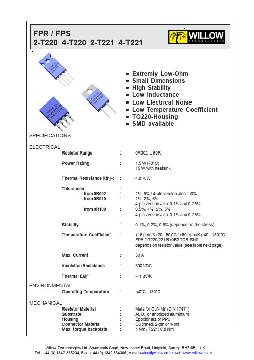
FPR2-T2210R068资料
元器件交易网
FPR / FPS
2-T220 4-T220 2-T221 4-T221 TEMPERATURE COEFFICIENT
250
2000 1000 + 15 ppm/K
200
TCR - Shift (ppm/K)
0
dR/R (ppm )
-1000 -2000 -3000
元器件交易网
FPR / FPS
2-T220 4-T220 2-T221 4-T221 DIMENSIONS
FPR 2-T221
FPR 4-T221
FPS 2-T220
FPS 4-T220
HOW TO ORDER FPR 2-T220 10R 0.25% FPR 2-T221 0R068 0.5% FPS 2-T220 1R0 1% FPR 4-T221 0R1 0.5%
Willow Technologies Ltd. Shawlands Court, Newchapel Road, Lingfield, Surrey, RH7 6BL, UK Tel. + 44 (0) 1342 835234, Fax. + 44 (0) 1342 834306, e-mail sales@ web
DERATING CURVE
120 Power ( % from nominal power) 100 80 60 40 20 0 25 50 85 100 115 130 Tem perature of the backplate (°C) 0,5% 0,2% % 0,1%
DIMENSIONS
FPR 2-T220
Stability Temperature Coefficient
贝士德FC说明书
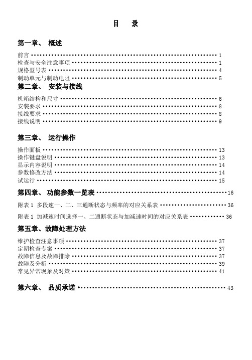
目录第一章、概述前言 (1)检查与安全注意事项 (1)规格型号表 (4)制动单元与制动电阻 (5)第二章、安装与接线机箱结构和尺寸 (6)安装要求 (8)接线要求 (8)接线说明 (9)第三章、运行操作操作面板 (13)操作键盘说明 (13)显示内容说明 (14)参数修改方法 (14)试运行 (15)第四章、功能参数一览表 (16)附表1 多段速一、二、三通断状态与频率的对应关系表 (36)附表1 加减速时间选择一、二通断状态与加减速时间的对应关系表 (36)第五章、故障处理方法维护检查注意事项 (37)定期检查专案 (37)故障信息及故障排除 (37)故障及分析 (39)常见异常现象及对策 (41)第六章、品质承诺 (43)第一章概述前言FC300系列变频器是针对各种专用场合而精心设计的一款多功能高性能产品。
调试参数简单实用,只须一键设置便可改为您需要的专用机型,再加上参数拷贝功能,使您在使用本变频器时变得异常的简单。
使用之前请务必熟读此说明书,便于您更好的使用此变频器,阅读后请妥善保管,对以后的维护,保护及其他使用场合有很好的帮助。
如在使用过程中存在着无法解决的问题,请务必由合格的专业电机工程人员安装调试及修改参数。
本手册中有频器使用更加安全。
检查与安全注意事项FC300系列变频器在出厂之前已经过测试和品质检验,在购买之后。
拆箱之前请检查产品包装是否因运输不慎而造成损失,产品的规格和型号,是否与定购机种相符,如有问题请与本公司联系。
拆箱后检查1 内含本机使用说明书一本,保修卡及合格证一张。
2检测变频器侧面的铭牌,以确定在您手上的产品是您说定购的产品。
变频器铭牌说明安全注意事项的注意事项,它们对我们的个人安全都很重要搬运和放置注意事项送电前● 所选用电源电压必须与变频器输入电压规格相同。
符号为接地端子,请确实将电机及变频器正确接地,以确保安全。
或停止,否则,会影响变频器的使用寿命。
● 主回路端子配线必须正确,()为电源输入端子,绝对不可接在上,否则在送电时,将造成变频器的损坏。
FHP20100中文资料

t 方波宽度(s)
Junction to Case
瞬态反向电流(mA)
10 TA = 125 °C 1
0.1 TA = 25 °C
0.01
热阻抗(℃/W)
VF20100C 0.001 10 1 0.01
20
30
40
50
60
70
80
90
100
0.1
1
10
100
图3. 单侧反向特性
10 000 TJ = 25 °C f = 1.0 MHz Vsig = 50 mVp-p 1000
瞬态反向电压(V)
图4. 单侧热阻抗
t 方波宽度(s)
电容(pF)
100
10 0.1 1 10 100
图5. 结温特性(单侧)
反向电压(V)
±0.20 1.30 ±0.10 2.80 ±0.10 (8.70) ø3.60 ±0.10 (1.70) 4.50 ±0.20
TA = 25 °C 1
热阻抗(℃/W)
TA = 125 °C
V(B,I)20100C 0.1 0 0.2 0.4 0.6 0.8 1.0 1.2 1.4 1.6 1 0.01
0.1
1
10
100
图1. 瞬态正向特性(单侧)
100 TA = 150 °C 10
瞬态正向电压(V)
图2. 热阻抗变化(单侧)
(1.00x45°)
9.75 ±0.30
MAX1.47 0.80 ±0.10
(3 0° )
0.35 ±0.10 2.54TYP [2.54 ±0.20]
#1 2.54TYP [2.54 ±0.20] 4.70 ±0.20
台达变频器02SS-SC手册

簡中-3
基本配線圖
下圖為 VFD-S 出廠時交流電機驅動器的標準配線圖 For VFDXXXSXXA/B/D/U
¾ 切斷交流電源后,交流電機驅動器數字操作器指示燈未熄滅前,表示交流電機驅動內 部仍有高壓十分危險,請勿觸摸內部電路及零組件。
¾ 絕對不可以自行改裝交流電機驅動器內部的零件或線路。 ¾ 絕不可將交流電機驅動器輸出端子 U/T1、V/T2、W/T3 連接至 AC 電源。
¾ ¾ ¾ ¾
¾
¾ ¾ NOTE ¾ ¾
交流電機驅動器是精密的電力電子產品,為了操作者及機械設備的安全,請務必交由專業的電機工程人員 安裝試車及調整參數,本手冊中有”危險”、”注意”等符號說明的地方請務必仔細研讀,若有任何疑慮的地 方請連絡本公司各地的代理商咨詢,我們的專業人員會樂于為您服務。
以下為特別需要注意的事項:
¾ 實施配線,務必關閉電源。
主 回 路端 子 的 規 格為M 3 . 0
短路片
制 動 電阻(選 購)
無熔絲斷路器
R NFB
S
T 異常或電源瞬間斷路
保護建議線路。此保
護線路利用變頻器多
功能輸出 端子, 當變
頻器發生異常時接
OFF
點導通將 電源斷開,
以保護電源系統。
出廠設定 正轉/停止
反 轉/停 止
多 異常復歸 功
能
輸 入
多 段 速指 令1
1.7
富强鑫FCS-2100注塑机操作说明书

2-3 開鎖模/調模設定頁…………………………………………… 15
2-4 射膠/加料設定頁……………………………………………… 18
2-5 頂出設定頁-托模、頂出、吹氣……………………………… 22
2-6 功能/時間設定頁……………………………………………… 25
2-7 特殊功能頁……………………………………………………. 28
.〔托模/吹氣〕畫面呼出按鍵。
.〔功能/時間設定〕畫面呼出按鍵。
.〔生產管制〕畫面呼出按鍵。
.〔中子設定〕畫面呼出按鍵。
.〔射出終點曲線〕畫面呼出按鍵。
.〔溫度追蹤曲線〕畫面呼出按鍵。
.〔清料/射座〕畫面呼出按鍵。
.〔印表〕畫面呼出按鍵。
6
(三)數字/文字輸入鍵 .數字鍵則是提供數值輸入之用。
本微電腦具有高度的擴充性,可依使用者的需求更改成使用者喜 愛的畫面,更可依使用者的特殊需求更改作動形式,但前提為機器本 體之硬體需符合需求,若有此方面的需求,請與原廠聯絡修改事宜。
4
螢幕
手
動
、
半
畫面切換鍵
自
動
方向鍵
、
全
自
動
模
式
鍵
手動動
作操作
英文字
鍵
母輸入
鍵
緊急停止
資料保 護鎖
3
FCS-2100 型控制器操作說明
導言
微電腦是操作者與機器的溝通工具,一台性能良好的機器必須輔 以聰明的操作者,才能發揮其強大的功能。本章節將詳述微電腦與機 器搭配的各項功能,包含狀態監視頁、溫度設定頁、開關模設定頁、 射出/加料設定頁、托模設定頁、時間/功能頁、特殊功能頁、生產管 制頁、檔案管理頁、中子設定頁、清料/射座設定頁、溫度曲線頁、 射出終點曲線頁、列印等頁次。請操作人員務必熟讀本章節後,才開 始進行微電腦之操作。
- 1、下载文档前请自行甄别文档内容的完整性,平台不提供额外的编辑、内容补充、找答案等附加服务。
- 2、"仅部分预览"的文档,不可在线预览部分如存在完整性等问题,可反馈申请退款(可完整预览的文档不适用该条件!)。
- 3、如文档侵犯您的权益,请联系客服反馈,我们会尽快为您处理(人工客服工作时间:9:00-18:30)。
Distinctive Characteristics
Slim .150” (3.8mm) body has the lowest profile in the industry and
allows close stacking of PC boards.
Highly visible legends and screwdriver actuator with
arrow position indication provide trouble-free
code setting.
Detent mechanism gives crisp, positive action
for accurate switch setting.
Use of heat resistant resin allows infrared
convection reflow soldering.
Gull-winged terminals ensure mechanical
stability during soldering and simplify solder
joint inspection.
Cam activated movable contact and gold contacts
assure contact reliability and continuity.
Tape-reel packaging meets EIA-481-2 Standard.
Coplanarity: all considered surfaces must lie between two parallel planes
that are a maximum distance apart of .0059” (0.15mm). (Additional
coplanarity details in Terms and Acronyms in the Supplement section.)
Actual Size
General Specifications
Electrical Capacity (Resistive Load)
Switching Rating:100mA @ 5V DC
Nonswitching Rating:100mA @ 50V DC
Other Ratings
Contact Resistance:100 milliohms maximum for circuit; 30 milliohms maximum for contact point
Insulation Resistance: 1,000 megohms minimum @ 250V DC
Dielectric Strength: 250V AC minimum for 1 minute minimum
Mechanical Life: 10,000 detent operations minimum
Electrical Life: 10,000 detent operations minimum
Notes: A detent operation is one actuator position operation or stepping.
A cycle is one 360° rotation. 10,000 detent operations equal
625 cycles for hexadecimal devices or 1,000 cycles for decimal devices.
Nominal Operating Torque:0.008Nm for decimal devices; 0.01Nm for hexadecimal devices
Contact Timing:Shorting (Avoid possible false signal by turning off power before switching.)
Materials & Finishes
Actuator: Glass fiber reinforced polyamide (UL94V-0)
Housing & Base: Glass fiber reinforced polyamide (UL94V-0)
Leaf Spring: Stainless steel
Movable Contacts: Copper alloy with gold plating
Stationary Contacts: Phosphor bronze with gold plating
Terminals: Phosphor bronze with gold plating
Environmental Data
Operating Temperature Range: –25°C through +85°C (–13°F through +185°F)
Humidity:90 ~ 95% humidity for 240 hours @ 40°C (104°F)
Vibration: 10 ~ 55Hz with peak-to-peak amplitude of 1.5mm traversing the frequency range & returning
in 5 minutes; 3 right angled directions for 2 hours
Shock: 50G (490m/s2) acceleration (tested in 6 right angled directions, with 5 shocks in each direction) Processing
Soldering:Reflow Soldering Recommended. See Profile A in Supplement section.
Note: During Reflow Soldering process, set the switch to the following position:
FR02FR10P, FR02FR16P: 0 position; FR02FC10P: 7 position; FR02FC16P: F position
Manual Soldering: See Profile A in Supplement section.
Cleaning:These devices are not process sealed. Hand clean locally using alcohol based solution.
Standards & Certifications
Flammability Standards:UL94V-0 rated actuator, housing, & base
UL Recognition The FR Series rotaries have not been tested for UL recognition or CSA certification.
or CSA Certification:These switches are designed for use in a low-voltage, low-current circuit.
When used as intended, the results do not produce hazardous energy.
TYPICAL SWITCH ORDERING EXAMPLE
ACTUATORS
F
Screwdriver Actuated
Adjusted with a flat tipped screwdriver
DESCRIPTION FOR TYPICAL ORDERING EXAMPLE
FR02FR10P-S
Real Coded
Gull Wing Terminals for Upright Mount
Screwdriver Actuated Decimal Actuator Positions
Packaged in Stick-Tube
Actuators are fully rotational either clockwise or counterclockwise.Actuator Colors: Orange for real coded devices; Yellow for complement coded devices.
Upright • Screwdriver Actuated
TYPICAL SWITCH DIMENSIONS
P
FR02FC10P
.039 .100
C
Decimal
Hexadecimal
PACKAGING
Each stick-tube contains 50 switches.
Switches must be ordered in 50-piece increments.
S
Stick-Tube
.413
.079
Switches must be ordered in 500-piece increments.This packaging meets EIA-481-2 Standard.
R
Tape-Reel
3ϒ
Direction of Feed
Each tape-reel of 550 pockets contains 500 switches. Minimum Leader Length: 15.748” (400mm)Minimum Trailer Length: 6.299” (160mm)。
