OMD系统操作
数控机床操作入门

目录第一章绪论近来来,数控技术的发展十分迅速,数控机床的普及率越来越高,在机械制造业中得到了广泛的应用。
制造业的工程技术人员和数控机床的操作与编程技术人员对数控机床及其操作与编程技术的需求越来越大。
数控机床是一种完全新型的自动化机床,是典型的机电一体化产品。
数控技术集计算机技术、成组技术、自动控制技术、传感检测技术、液压气动技术以及精密机械等高新技术于一体,是现代化制造技术的基础技术和共性技术。
随着数控机床的广泛应用,急需培养大批能熟练掌握现代数控机床编程、操作、维修的工程技术人员。
为普及与提高数控加工新技术,本教程针对目前广泛运用的FANUC和SIEMENS两种系统进行操作介绍。
第二章数控车床结构第一节数控车床简介数控车床分为立式数控车床和卧式数控车床两种类型。
立式数控车床用于回转直径较大的盘类零件的车削加工。
卧式数控车床用于轴向尺寸较长或小型盘类零件的车削加工。
相对于立式数控车床来说,卧式数控车床的结构形式较多、加工功能丰富、使用面广。
本教程主要针对卧式数控车床进行介绍。
卧式数控车床按功能可进一步分为经济型数控车床、普通数控车床和车削加工中心。
1.经济型数控车床采用步进电动机和单片机对普通车床的车削进给系统进行改造后形成的简易型数控车床,成本较低,但自动化程度和功能都比较差,车削加工精度也不高,适用于要求不高的回转类零件的车削加工。
2.普通数控车床根据车削加工要求在结构上进行专门设计并配备通用数控系统而形成的数控车床,数控系统功能强,自动化程度和加工精度也比较高,适用于一般回转类零件的车削加工。
这种数控车床可同时控制两个坐标轴,即X轴和Z轴。
3.车削加工中心在普通数控车床的基础上,增加了C轴和动力头,更高级的机床还带有刀库,可控制 X、Z和 C三个坐标轴,联动控制轴可以是(X、Z)、(、C)或(Z、C)。
由于增加了C轴和铣削动力头,这种数控车床的加工功能大大增强,除可以进行一般车削外,还可以进行径向和轴向铣削、曲面铣削、中心线不在零件回转中心的孔和径向孔的钻削等加工。
激光甲烷检测车OMD操作使用规程

OMD激光甲烷检测仪操作使用规程一、开机前检查1、车辆检查1.1、检查车辆外观是否完好整洁,每周对车辆进行清洗。
1.2、检查车辆行驶证、警灯使用证是否在有效期内并符合相关规定。
1.3、检查车辆刹车系统、指示灯、安全带、转向系统等是否完好正常。
1.4、检查车载仪器、设备是否齐全,能否正常使用。
1.5、由驾驶人员填写《OMD车辆运行检查表》,并签字,由巡线队队长进行核准签字。
2、OMD操作检查2.1、检查设备是否完整,所有数据线是否连接完好。
2.2、接收器镜面是否干净,定期使用柔软的干抹布擦拭干净。
2.3、检查静电带是否装好(静电带须连接地面至少3CM)。
2.4、检查激光探测杆螺丝的松紧程度,不能太紧或太松,保证用手轻拉不会松动。
2.5、由驾驶人员填写《OMD操作检查表》,并签字二、设备操作1、打开逆变器电源以及电瓶开关(在副驾驶座储物盒)。
2、打开电脑以及OMD控制器系统电源开关。
3、OMD控制器上面的英文ALARM SET POINT设置报警值 CALIBRATION TEST标定测试DISPLAY FUNCTION 显示功能 SAMPLE采样 LIGHT灯光强度 HOLD 保持PPM RANGE 显示PPM范围 LIGHT SOURCE 激光开关SYSTEM POWER 系统电源开关 CONTRAST 对比度 SPEAKER 声音大小调节4、根据面板上面的提示Push Display to continue(按下功能键以继续),即按下左边白键。
5、再按下左边白键,屏幕显示SYSTEM WARMING UP(系统预热中),等待。
6、当控制器产生“嘀”的一声响,屏幕显示Push Light Source To BEGIN(按下激光开关键以开始),即按下激光开关键。
7、屏幕上面的英文PRESENT 当前测试值 MAXIMUM 最大值 SETPOINT设置报警值8、车载激光数据及电源线连接示意图其中红色为串口数据线,负责数据的传输;蓝色为OMD的电源线;绿色为显示器数据线,负责将前方的数据显示在控制器上;两条黑色则为激光采集数据线,负责采集数据;粉红色为GPS数据传输线。
FANUC技术和操作技巧
请问何谓MDI键盘为全键盘,谢谢答:数字键与字母键是独立分开的,比标准键盘要长。可以输入# 等特殊字符用于MACRO B
7、 专用操作面板占用资源问题,急切需要回答,谢谢谢谢 (0MD)
老师您好,我们用的是0md系统,0md系统有专用操作面板接口,并且里面有管理软件。他占用的资源是X20、X21、X22、Y51,可我们不需要专用的面板,我们自己开发,用到了X20、X21、X22、Y51这些资源,发现这些资源不能用,如何解决。 我们的梯形图长度是700,可是发现生成的代码是从0000-3700,那么0000-3000应该是你们专用操作面板的管理软件,这个管理软件影响我们的X20、X21、X22、Y51正常运行,如何取消这个管理软件的运行。我们是通过232串口把程序下载进去的,每次下载都要从0000开始到3700结束,我们想知道如何只需要将3000-3700这段程序下载进去。谢谢,急切您的解答答:从LADDER PROGRAMMER MENU中选 01从切换到PMC SYSTEM PARAMETEROPERATOR PANEL = NO; 1=YES/0=NO选0这样就可以不使用专用操作面板接口
9、 关于0i MC数控系统的配置问题? (0i MC)
你好 我是西安的一家公司,我公司的数控设备原用的是FANUC 0I MA数控系统,配的是α和β系列的伺服放大器以及相应的α和β系列的伺服电机,现该为FANUC OI MC数控系统以后能否仍用原来的α和β系列伺服放大器和伺服电机,还是必须用αI和βI系列的伺服放大器和伺服电机,这两者有什么区别吗? 希望能尽快给与答复!谢谢!答:你好,0iA和0IB/0IC的区别就是放大器和电机不同,前者是α/β系列,而后者是αi和βi系列,不能互换。
OMD培训资料-新

销售终端参与计划
新OMD流程的业务价值 流程的业务价值
对客户
缩短客户交车等待时间: 缩短客户交车等待时间:经销商可以用未来9
周订单资源中预计最快下线的车辆来匹配(或更 改后匹配)客户的购车需求,缩短客户的实际等 待时间
2
对经销商
经销商提前掌握未来9周的资源: 经销商提前掌握未来 周的资源:经销商能 周的资源
订单管理与分销(OMD)流程及系统推广 流程及系统推广 订单管理与分销 - 经销商培训材料
部门 Department 版本号 Version 保密级别 Secrecy level 更新日期 Date
OMD Project V 0.4 Internal 2011/6/28
SVW OMD Implementation Project Internal
5
每月第四 个工作日 提报本区域特 种车预测
3
经销商
每月第二 个工作日 提交3+2预测
SVW OMD Implementation Project Internal
18
预测参考值的计算
零售任务
车型大类总量 可用资源 各6位码数量
前三月 平均零售量
第一轮产销平衡 第二轮产销平衡 第三轮产销平衡
3
SSS
总部销售 需求
5
分配配额
8
预配车
10
配车优化
11
资金优化 车辆运输
2
分销中心
调整特种 车预测
6
分配特种 车配额
1
经销商
提交3+2 预测
7
经销商提报订单 修改订单/查询下线周
12
经销商打 款
交车/零售
SVW OMD Implementation Project Internal
OMD系统销售员身份信息维护操作手册pdf
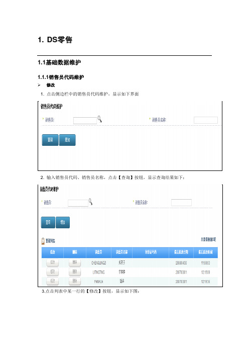
1. DS零售1.1基础数据维护1.1.1销售员代码维护¾修改1. 点击侧边栏中的销售员代码维护,显示如下界面2. 输入销售员代码、销售员名称,点击【查询】按钮,显示查询结果如下:3.点击列表中某一行的【修改】按钮,显示如下图:点击【确认】按钮时,程序会校验销售员名称和身份证号码是否为空,并验证身份证的有效性,全部通过完成修改操作。
¾新增1. 点击界面上的【增加】,增加新的销售员信息2.录入销售员信息在该界面中录入销售员、销售员名称、身份证号码,点击【确认】按钮,校验输入框中的数据是否为空,并校验身份证号码的有效性。
1.2 零售业务1.2.1零售订单(发票)维护¾修改1.点击侧边栏中的零售订单(发票)维护,显示如下界面2.输入车辆代码、颜色代码、零售订单号、用户名称、日期,点击【查询】按钮,显示查询结果如下:3.点击列表中某一行的【修改】按钮,显示如下图:(1) 修改销售员后,如果销售员是已经在销售员代码维护界面里维护过的,例如下图:点击【选择】按钮后,返回到原来的修改屏,点击【确认】按钮后,显示如下图:点击【确定】按钮后,程序会通过校验销售员名称,进而校验身份证号码是否为空,因为此销售员已经在销售员代码维护界面维护过身份证,所以此时全部通过完成修改操作,返回前一屏。
(2) 修改销售员后,如果销售员未在销售员维护界面里维护过的,例如下图:点击【选择】按钮后,返回到原来的修改屏,点击【确认】按钮后,显示如下图:点击【确定】按钮后,程序会通过校验销售员名称,进而校验身份证号码是否为空,因为此销售员未在销售员代码维护界面维护过身份证,所以此时会提示如下图:后,返回零售订单(发票)维护进行维护操作。
FANUC OMD系统操作编程说明书
该指令是我们最常用的指令之一。
假设ቤተ መጻሕፍቲ ባይዱ前刀具所在点为X-50. Y-75.,则如下程序段
N1 G01 X150. Y25. F100;
N2 X50. Y75.;
2.1
G00给定一个位置。
格式:G00 IP;
IP在本说明书中代表任意不超过三个进给轴地址的组合,当然,每个地址后面都会有一个数字作为赋给该地址的值,一般机床有三个或四个进给轴即X,Y,Z,A所以IP可以代表如X12. Y119. Z-37.或X287.3 Z73.5 A45.等等内容。
G00这条指令所作的就是使刀具以快速的速率移动到IP指定的位置,被指令的各轴之间的运动是互不相关的,也就是说刀具移动的轨迹不一定是一条直线。G00指令下,快速倍率为100%时,各轴运动的速度:X、Y、Z轴均为15m/min,该速度不受当前F值的控制。当各运动轴到达运动终点并发出位置到达信号后,CNC认为该程序段已经结束,并转向执行下一程序段。
*G91
03
增量值指令方式
G92
00
工件零点设定
*G98
10
固定循环返回初始点
G99
10
固定循环返回R点
从表1.1中我们可以看到,G代码被分为了不同的组,这是由于大多数的G代码是模态的,所谓模态G代码,是指这些G代码不只在当前的程序段中起作用,而且在以后的程序段中一直起作用,直到程序中出现另一个同组的G代码为止,同组的模态G代码控制同一个目标但起不同的作用,它们之间是不相容的。00组的G代码是非模态的,这些G代码只在它们所在的程序段中起作用。标有*号的G代码是上电时的初始状态。对于G01和G00、G90和G91上电时的初始状态由参数决定。
上海迅时智能电话系统OM系列IPPBX开局指导教程

主要型号
4FXS, 8FXS, 12FXS, 4FXO, 8FXO, 12FXO, 2FXS/2FXO, 4FXS/4FXO, 6FXS/2FXO, 8FXS/4FXO, 10FXS/2FXO
OM12外观说明
前面板
后面板
OM80主要型号
主要型号
16FXS, 32FXS, 48FXS, 8FXS/8FXO, 24FXS/8FXO, 40FXS/8FXO, 16FXS/16FXO, 32FXS/16FXO, 24FXS/24FXO
操作员
不允许
部分参数 允许
网络参数配置
设备若需要使用域名或文字转欢迎词功能,需打开DNS服务,并填写正确的 DNS服务器的地址。
拨号规则
1、分机直拨外线时无需加前缀,但内部分机互拨要加*。 2、IP外线与模拟外线同时存在时,智能外线才有效。
总机配置
1、可以自定义上下班时间,并且根据设置选择不同的欢迎词。 2、可设置5个分机为总机组,并选择不同的话务分配方式。 3、秘书功能,所有来电先转秘书分机,由秘书分机判断是否需要转接来电。
常见问题处理
登录不上Web管理员界面
• 将话机连接到Phone端口,摘机拨 ## 听设备的网络参数是否正确; • 检查设备所在局域网; • 检查局域网到设备之间的连接。
来电时话机不振铃
• 通过更换话机,判断原话机振铃功能是否正常。 • 点击 系统配置 > 模拟分机,确认号码显示传输模式与话机匹配。 • 调整设备提供的话机振铃频率。
登录
为了安全,首次登录后,请立即 修改管理员与操作员密码。
缺省登录密码 型号
OM4 OM12 OM80 OM200
权限说明 操作员
operator operator operator operator
OMD100 安装和操作说明说明书
—I N S TA LL ATI O N A N D O PER ATI N G I N S TR U C TI O NAutomatic control unit OMD100— A u t o m a t i c c o n t r o l u n i t 34O M D 100 r e v . C / 1S C C 390124M 02022AUTO M ATI C CO NTRO L U N IT, O M D100—Table of contents1. Introduction 41.1 Use of symbols 41.2 Explanations of abbreviations and terms 42. Product overview 52.1 Typical applications 63. Description 73.1 OMD100 switching sequence 73.1.1 Line 1 priority 73.1.2 No line priority 83.1.3 Manual back switching 94. Installation 104.1 Dimensional drawings 104.2 Mounting 114.2.1 Automatic control unit OMD100, door mounting 114.2.2 Automatic control unit OMD100, DIN-rail mounting 125. Connecting 135.1 Power circuit 135.2 Control circuit 145.2.1 Control circuit diagram OMD100 with motorized440...125_CMA_ 1OTM5.2.2 Control circuit diagram OMD100 with motorizedOTM160...2500_CM_ 155.2.3 Connectors, OMD100 165.2.4 OMD100 outputs 175.2.5 OMD100 inputs 176. Operating 186.1 Automatic control unit in Manual Mode 18 – 206.2 Automatic control unit in Automatic Mode 206.3 Selection of delay time, voltage threshold andTEST function 21 – 226.4 Operating modes 236.4.1 Operating modes in OMD100 236.4.2 Choice of Operating mode in OMD100 24 – 263 AU TO M ATI C CO NTR O L U N IT, O M D1007. Using automatic control unit OMD100 277.1 Interface 277.1.1 Keypad 27 – 287.1.2 LEDs 28 – 297.2 Configuration 307.2.1 Rotary switches 307.2.2 DIP switches / parameter setting 31 – 327.3 TEST sequence 338. Technical data of the automatic control unit OMD100 349. Troubleshooting 359.1 OMD100 359.2 Explanations of internal faults, OMD100 369.3 Change-over switch does not respond 36 – 3710. Accessories 3810.1 Fastener 384AUTO M ATI C CO NTRO L U N IT, O M D100—1. IntroductionThis manual describes the installation and the basic operation of the OMD100 automatic control unit. The instructive part is followed by a section on available accessories.—1.1 Use of symbolsOMD The control unit of automatic transfer switching equipment, common type name for the automatic control unitOMD100 The automatic control unit, basic version with simplified functionalities LN1-Switch I Power supply line, eg. the primary lineLN2-Switch IIPower supply line, eg. the secondary line used in emergency cases Test sequence A sequence to test the functionality of the OMD and the connected change-overswitchTs Switching delay TbsBack switching delayCaution: provides important information or warns about a situation that may have a detrimental effect on equipment.General warning: warns about a situation where something other than electrical equipment may cause physical injury to a person or damage to equipment.Hazardous voltage: warns about a situation where a hazardous voltage may cause physical injury to a person or damage to equipment.Information: provides important information about the equipment.—1.2 Explanations of abbreviations and terms5AU TO M ATI C CO NTR O L U N IT, O M D100—2. Product overviewThe automatic transfer switch concept is applied to any application requiring switching from the primary power line to secondary power line to ensure the supply of loads.OMD100 is the basic version of the control unit of automatic switching equipment. It has two sensors to monitor two three-phase power lines, both able to work with single phase, too. OMD100 can measure voltage, frequency and the phase balance of the primary and secondary power line. OMD100 is able to command a single motorized change-over switch. The neutral has to be always connected.Figure 2.1Automatic control unit OMD1001 User interface consists of LEDs, keypad and rotary switches2 Connectors to connect automatic control unit with application and motorized change-over switch3 DIP switches for parameter setting4 Places for fasteners, used when OMD100 is mounted on the door 5Place for DIN rail516AUTO M ATI C CO NTRO L U N IT, O M D100Figure 2.2 Network line a - Network line bAutomatic control unit type OMD100 is designed for single and three-phase distribution systems in diverse applications. OMD100 is supplied from Line 1 and Line 2 and can be used without external power supply.Figure 2.3OMD100 has two sensors to monitor two three-phase power lines, both able to work with single phase, too. Neutral has to be always connected.—2.1 Typical applicationsNetwork line a – Network line bIn case of loss of the primary power line, the OMD100 device manages the switching to a secondary power line used as an emergency source.7AU TO M ATI C CO NTR O L U N IT, O M D100—3. Description—3.1 OMD100 switching sequence3.1.1 Line 1 priorityThe switching sequence can be summarized in following steps:An anomaly occurs on the Line 1 Switching delayChange-over switch (Switch I) to the position OChange-over switch (Switch II) to the position IIAnd the back switching sequence can be summarized in the following steps:The Line 1 will start the normal functioning Back switching delayChange-over switch (Switch II) to the position OChange-over switch (Switch I) to the position IFigure 3.1 Automatic Switching Sequence, Line 1 priorityTs : Switching delay, Tbs :Back switching delay8AUTO M ATI C CO NTRO L U N IT, O M D1003.1.2 No line priorityThe switching sequence can be summarized in following steps: An anomaly occurs on the Line 1Switching delayChange-over switch (Switch I) to the position OChange-over switch (Switch II) to the position IIAnd the back switching sequence can be summarized in the following steps: The Line 1 will start the normal functioningChange-over switch stays in position IIAn anomaly occurs on the Line 2Back switching delayChange-over switch (Switch II) to the position OChange-over switch (Switch I) to the position ITs: Switching delay, Tbs:Back switching delayFigure 3.2 Automatic Switching Sequence, no line priority9AU TO M ATI C CO NTR O L U N IT, O M D100Figure 3.3 Automatic Switching Sequence, manual back switchingTs : Switching delay, Tbs :Back switching delay3.1.3 Manual back switchingThe switching sequence can be summarized in following steps:An anomaly occurs on the Line 1 Switching delayChange-over switch (Switch I) to the position OChange-over switch (Switch II) to the position IIAnd the back switching sequence can be summarized in the following steps:The Line 1 will start the normal functioning Change-over switch stays in position II An anomaly occurs on the Line 2 Back switching delayChange-over switch (Switch II) to the position O The Line 2 will start the normal functioning Switching delayChange-over switch (Switch II) to the position IIA 0725210AUTO M ATI C CO NTRO L U N IT, O M D100—4. Installation—4.1 Dimensional drawingsFigure 4.1OMD100, dimensions of the device—4.2 Mounting4.2.1 Automatic control unit OMD100, door mountingThe automatic control unit OMD100 can be mounted on the door with the fastener OMZD1,4.2.2 Automatic control unit OMD100, DIN-rail mountingThe automatic control unit OMD100 can be mounted on the 35 mm DIN-rail and the door drilling, if needed, according to Figure 4.3.—5. Connecting—5.1 Power circuitOperating voltage:Main voltage: 380 Vac (±20 %)Phase voltage: 220 Vac (±20 %)Frequency: 50 Hz (±10 %)Neutral must always be connected.Phase setting with DIP switch: Single phase or Three-phase (default).—5.2 Control circuitFigure 5.1 Control circuit diagram OMD100 with motorized OTM40…125_CMA_Equipment earth must always be connected.5.2.1 Control circuit diagram OMD100 with motorized OTM 40...125_CMA_A 07281Signaling OK/Equipment AlarmEquipment earthSupplyEquipment earth from DIN-railOMD100MotorizedOTM40-125F_CMAL1L2L3NL1L2L3NCOM D01D02COM COM D03DI3DI1DI2DI L1L2L3NL1L2L3ND06COM D06OK COM AlarmX5X4X1X2LN1LN2M e a s u r e m e n tM e a s u r e m e n tFigure 5.2 Control circuit diagram OMD100 with motorized OTM160…2500_CM_Equipment earth must always be connected.5.2.2 Control circuit diagram OMD100 with motorizedOTM160...2500_CM_A 07256OMD100MotorizedOTM160-2500_CMO A 1G 10S w i t c h I a u x i l i a r y c o n t a c tS w i t c h I I a u x i l i a r y c o n t a c tSignaling OK/Equipment AlarmEquipment earthSupplyEquipment earth from DIN-railL1L2L3NL1L2L3NCOM D01D02COM COM D03DI3DI1DI2DI D06COM D06X2X1J1O A 1G 10M e a s u r e m e n tM e a s u r e m e n tL1L2L3NL1L2L3NLN1LN2OK COM Alarm5.2.3 Connectors, OMD100Table 5.1 Connectors OMD 100Figure 5.3 Connectors, OMD100Connector DescriptionX11:1X11:2X11:3X11:4Supply I: L1Supply I: L2Supply I: L3Supply I: N X12:1X12:2X12:3X12:4Supply II: L1Supply II: L2Supply II: L3Supply II: NX21:1X21:2X21:3X21:4Voltage supply from motor operator OME_ Common Output to close switch I NO Output to close switch IINOVoltage supply from motor operator OME_ Common X22:1X22:2X22:3X22:4Voltage supply from motor operator OME_ Common Output to open switch I and switch II NOReserved ReservedX24:1X24:2X24:3Output to signal OK (no alarm)CommonOutput to signal AlarmX31:1X31:2X31:3X31:4Manual / Alarm input from handle Status of switch I auxiliary contact Status of switch II auxiliary contactVoltage supply from the automatic control unit OMD100X61Equipment earthK A 0028721212112341234123412341234123X26X27X28X31X21X22X11X24X12X615.2.4 OMD100 outputs5.2.4.1 Opening/closing command to change-over switches, X21 (DO1-DO3)These outputs command the change-over switch to open and close Switch I or Switch II.To guarantee the highest-level safety OMD100 monitors the correct operation of the change-over switch after a command has been sent. If the feedback of the switch status is not received within 3 seconds of the sending of the command, the device considers it as a failed command and operates as follows:An alarm is generated: DO6 activate.Alarm LED switches on.Alarm is set off by pushing the AUTO key. After that the device is always in the Manual Mode to prevent unwanted operation of the change-over switch.Exactly the same operations are performed on the secondary line (LN2-Switch II) during the back switching sequence.5.2.4.2 Alarm signaling, X24 (DO6)When the relay contact Alarm (X24:3) is open and contact OK (X24:1) is closed, the automatic transfer logic is enabled. If the relay contact Alarm (X24:3) is closed and the contact OK (X24:1) is open the automatic transfer logic is disabled and an alarm is active.5.2.5 OMD100 inputs5.2.5.1 Switch status input, X31:2 (DI1), X31:3 (DI2)These two inputs are connected to change-over switch auxiliary contacts. Input X31:2 (DI1) is connected to LN1-Switch I and input X31:3 (DI2) is connected to LN2-Switch II (Switch I / II open= input inactive, Switch I / II closed = input active). Auxiliary contacts are in-built in motorized OTM40…125_CMA_. If OMD100 is used with motorized OTM160…2500_CM_, use always typeOA1G10 auxiliary contacts with DI1 and DI2. See the wiring diagrams on Figure 5.1 and Figure 5.2.5.2.5.2 Force manual, X31:1 (DI3)When the handle is attached this input is closed and OMD100 is forced to Manual Mode. To set the OMD100 back to the Automatic Mode the handle must be removed and the AUTO key pushed (Auto LED is ON).—6. OperatingNever open any covers on the product. There may be dangerous external control voltages inside the automatic transfer switch even if the voltage is turned off.Never handle control cables when the voltage of the automatic transfer switch or external control circuits are connected.Exercise sufficient caution when handling the unit.—6.1 Automatic control unit in Manual ModeSelecting the automatic control unit OMD100 to the Manual Mode:a. Make sure that the power LED is ON, see the Figure 6.1/.b. If the Auto LED is OFF /, the automatic control unit is in Manual Mode.c. If the Auto LED is ON, push the Auto key once /. The Auto LED switches to OFF and theautomatic control unit OMD100 is in Manual Mode /.Figure 6.1OR99Manual modeManual modeTo select the switch to operate by the automatic control unit OMD100 in Manual Mode:a.Push the appropriate I, O or II key.b.When pushing the I-key (see the Figure 6.2/, the I-switch will be in theON position (the status and the line indication, see the Figure 6.2/ and the II-switch will be in the OFF position. If the I-switch is already in the ON position, pushing the I-key does not have any influence.c.When pushing the O-key, the I-switch will be in the OFF position. The II-switch remains in theOFF position.d.When pushing the II-key, the II-switch will be in the ON position and the I-switch will be in theOFF position.e.If you push the I-key while the II-switch is in the ON position, first the II-switch opens (OFFposition) and then the I-switch closes its contacts (ON position).Figure 6.2 Selecting the switch to operate, the switch status and the chosen line indication with LEDs in OMD100If a new command is given before the switch has reached the position of the previouscommand, the fuse (F1) of the motor operator may operate.Figure 6.4See the OMD100 Automatic Mode operation in Section 7.Figure 6.3 Manual Mode controlPushing of the O-key (= O-command) will override the commands of the other keys. For example, if you simultaneously give an O-command and another command (I or II), the motorized change-over switch OTM_C is driven to the position O.—6.2 Automatic control unit in Automatic ModeSelecting the automatic control unit OMD100 to the Automatic Mode:a. Make sure that power LED is ON. If Auto LED is ON/, the automatic control unit is in Automatic Mode.b. If Auto LED is OFF/, check that the Lim rotary switch is not in the TEST or SETUP position/.c.Push the Auto key once/. The Auto LED switches ON and the automatic control unit OMD_ is in AutomaticMode/K A 00212Automatic modeOR4Automatic—6.3 Selection of delay time, voltage threshold andTEST functionThe delay time and the voltage threshold are set by the rotary switches in automatic control units OMD100.Ts / Tbs = Delay times for automatic switchingThe delay time is the time before activating the switching sequence and the back switching sequence. User can choose two types of settings for delay times:Choice 1: Darker side of the rotary switchAvailable selections for the delay times are: 0, 5, 10 and 30 s. When this side is used the back switching delay Tbs is always same as switching delay Ts.Choice 2: Lighter side of the rotary switchAvailable selections for the delay times are: 0, 5, 10 and 30 s. When this side is used the back switching delay Tbs is always set to 300s.Lim = Voltage threshold with SETUP and TEST functionThe available selections for voltage threshold in OMD100 are: ± 5, ± 10, ± 15, ± 20 %. By setting the voltage threshold, the unbalance is also set to the same level.When the user wants to enter to the SETUP mode, the automatic control unit has to be set to manual mode and Lim rotary switch has to be set to SETUP position. In SETUP mode it is possible to choose between three operating modes: standard switching mode, no priority mode or manual back switching mode. In the SETUP –mode user must also choose between automatic OTM_C_D, motorized OTM40…125_CMA_ or motorized OTM_160…2500_CM_ change-over switch.See Section 6.4.2 Choice of Operating mode in OMD100.When the Lim rotary switch is set to the TEST position, the automatic control unit OMD100 enters the test sequence. In test sequence it is possible to simulate switching and back switching sequences step by step by pushing the AUTO key.Figure 6.5 Selection of delay time and voltage threshold in OMD100Steps in the TEST sequence are:1.Push AUTO; change-over switch to position II2.Push AUTO; change-over switch to position IAfter final step, the TEST sequence restarts. The user can stop the TEST sequence by turning the Lim rotary switch back to the voltage threshold wanted. After stopping the TEST sequence the device returns to the MANUAL mode. By pushing AUTO key once after stopping test sequence the device is set to the AUTO mode.Figure 6.6 Lim rotary switch is set to the TEST function in OMD100—6.4 Operating modes6.4.1 Operating modes in OMD1006.4.1.1 Normal switching sequence + automatic OTM_C_D or motorized OTM40…125_CMA_ This operating mode is used when user has automatic OTM_C_D change-over switch or motorized OTM40…125_CMA_ and line priority is Line 1 – Switch I.6.4.1.2 No priority mode + automatic OTM_C_D or motorized OTM40…125_CMA_This operating mode is used when user has automatic OTM_C_D change-over switch or motorized OTM40…125_CMA_ and neither of the lines has priority. No line priority means that after switching sequence the device remains on the Line 2 although the Line 1 starts to work properly. The back switching is performed only if the Line 2 fails.6.4.1.3 Manual back switching mode + automatic OTM_C_D or motorizedOTM40…125_CMA_This operating mode is used when user has automatic OTM_C_D change-over switch or motorized OTM40…125_CMA_ and the automatic back switching sequence has to be inhibited for example while performing maintenance on the Line 1. If the Line 2 fails the switch is changed to the position O.6.4.1.4 Normal switching sequence + motorized OTM160…2500_CM_This operating mode is used when user has motorized OTM160…2500_CM_ change-over switch and line priority is Line 1 – Switch I.6.4.1.5 No priority mode + motorized OTM160…2500_CM_This operating mode is used when user has motorized OTM160…2500_CM_ change-over switch and neither of the lines has priority. No line priority means that after switching sequence the device remains on the Line 2 although the Line 1 starts to work properly. The back switching is performed only if the Line 2 fails.6.4.1.6 Manual back switching mode + motorized OTM160…2500_CM_This operating mode is used when user has motorized OTM160…2500_CM_ change-over switch and the automatic back switching sequence has to be inhibited for example while performing maintenance on the Line 1. If the Line 2 fails the switch is changed to the position O.Figure 6.7 Selecting the automatic control unit OMD100 to Manual Mode3. Press AUTO button to choose the mode. The Operation modes are indicated by LEDs accordingthe Table 6.1, see next page.Figure 6.9 Choosing the Operation mode by pressing the AUTO button. See the Table 6.1 of LED indications for wanted Operation modeFigure 6.8 Setting of SETUP mode with Lim rotary switch in automatic control unit OMD1002. Choose SETUP mode with Lim rotary switch according to the Figure 6.86.4.2 Choice of Operating mode in OMD1001. Set device to MANUAL mode according the Figure 6.7ORK A 00199Manual modeManual modeTable 6.1 Indications of the Operating modes in automatic control unit OMD1004. Set Lim rotary switch back to original positionFigure 6.10 Setting of SETUP mode with Lim rotary switch in automatic control unit OMD 1005. Set device to AUTO mode according to the Figure6.11.Figure 6.1112Automatic modeOR4Automatic—7. Using automatic control unit OMD100—7.1 Interface7.1.1 KeypadFigure 7.1 Interface of OMD100Figure 7.2 Keypad on OMD100AUTO keySelecting the automatic control unit OMD100 to the manual or automatic mode. An active alarm can reset by the AUTO key.O keySetting the motorized change-over switch OTM_C to the OFF position in manual and auto mode; both switches (I and II) are in the OFF position. After pressing the O-key the automatic control unit OMD100 is always in manual mode.I keySetting in manual mode the motorized change-over switch OTM_C to position I, when the I-switch will be in the ON position and the II-switch will be in the OFF position.II keySetting in manual mode the motorized change-over switch OTM_C to position II, when the II-switch will be in the ON position and the I-switch will be in the OFF position.7.1.2 LEDsFigure 7.3 LEDs on OMD100Line 1 status (LN1)A red LN 1 LED signals the status of the line LN 1. Line status and indication is explained in the Table 7.1.Line 2 status (LN2)A red LN 2 LED signals the status of the line LN 2. Line status and indication is explained in the Table 7.1.Line Status LED IndicationVoltage OK ONNo voltage OFFOvervoltage Fast blinking (5 Hz, 50 % ON / 50 % OFF)Undervoltage Blinking (1 Hz, 50 % ON / 50 % OFF)Invalid frequency Blinking (1 Hz, 90 % ON / 10 % OFF)Unbalance Blinking (1Hz, 10 % ON / 90 % OFF)Table 7.1 Line status indicationSwitch in position I (I)A red I LED is ON, when the motorized change-over switch OTM_C is in the I position (the I-switch is ON and the II-switch is OFF), the LED is OFF otherwise. If transition from the O position to the I position fails, the I LED will blink.Switch in position II (II)A red II LED is ON, when the motorized change-over switch OTM_C is in the II position (the II-switch is ON and the I-switch is OFF), the LED is OFF otherwise. If transition from the O position to the II position fails, the II LED will blink.AlarmA red Alarm LED signals an external alarm. Alarm status is explained in the Table 7.2. An active alarm is set off by pushing the AUTO key.Alarm Status LED IndicationHandle attached ONSwitching logic alarm BlinkingNo alarm OFFTable 7.2 Alarm status indicationNOTE: When the handle is removed, the automatic control unit will stay in manual mode and the Alarm LED will be OFF.When the Alarm LED is ON or blinking, check the state of the motorized change-over switchand repair the possible fault situation. An active alarm is set off by pushing the AUTO key.AutoA green Auto LED signals the automatic or the manual mode. When the OMD100 is in automatic mode, the Auto LED is ON. When the device is in manual mode, the Auto LED is OFF. In test sequence the Auto LED is blinking.PowerA green Power LED signals the power status. When power is ON, the Power LED is ON.—7.2 Configuration7.2.1 Rotary switchesTs / Tbs = Delay times for automatic switchingThe delay time is the time before activating the switching sequence and the back switching sequence. User can choose two types of settings for delay times: Choice 1: Darker side of the rotary switchAvailable selections for the delay times are: 0, 5, 10 and 30 s. When this side is used the back switching delay Tbs is always same as switching delay Ts.Choice 2: Lighter side of the rotary switchAvailable selections for the delay times are: 0, 5, 10 and 30 s. When this side is used the back switching delay Tbs is always set to 300 s.Lim = Voltage threshold with SETUP and TEST functionThe available selections for voltage threshold in OMD100 are: ±5, ±10, ±15, ±20 %.When the user wants to enter to the SETUP mode, the automatic control unit has to be set to manual mode and Lim rotary switch has to be set to SETUP position. In SETUP mode it is possible to choose between three operating modes: standard switching mode, no priority mode or manual back switching mode. In the SETUP –mode user must also choose between automatic OTM_C_D, motorized OTM40…125_CMA_ or motorized OTM_160…2500_CM_ change-over switch. . See Section 6.4.2 Choice of Operating mode in OMD100.When the Lim rotary switch is set to the TEST position, the automatic control unit OMD100 enters the test sequence. In test sequence it is possible to simulate switching and back switching sequences step by step by pushing the AUTO key.Figure 7.4 Selection of delay time and voltage threshold, the factory settings are shown in the figure31AU TO M ATI C CO NTR O L U N IT, O M D100Automatic control unit OMD100 has a total of four (4) adjustable parameters. The parameter settings are performed by the DIP switch and by the rotary switches.Ph Number of phases, setting by DIP switch S23-1Ts Switching delay, setting by Ts / Tbs rotary switch, see Section 7.2.1Tbs Back switching delay, setting by Ts / Tbs rotary switch, see Section 7.2.1THRVoltage threshold, setting by Lim rotary switch, see Section 7.2.1Figure 7.5 Place of the DIP switch7.2.2 DIP switches / parameter settingOnly an authorised electrician may perform the electrical installation and maintenance of automatic transfer switches. Do not attempt any installation or maintenance actions when an automatic transfer switch is connected to the electrical mains. Before starting work, make sure that the switch is de-energised.The parameter setting of automatic control unit OMD100 is performed by the DIP switch. The DIP12341234ON DIPON DIP S23S2432AUTO M ATI C CO NTRO L U N IT, O M D100DIP switch S23-1 to set phase system S23-1 PositionPhase systemOFF three-phase (default)ON single phaseDIP switch S23-2 is not in use.Figure 7.6 DIP switches in OMD100, the positions are factory default settings7.2.2.1 Parameter settings by DIP switches S2333AU TO M ATI C CO NTR O L U N IT, O M D100When the Lim rotary switch is set to the TEST position, automatic control unit OMD100 enters the test sequence. While entering the test sequence OMD100 blinks all LEDs twice to give the information that the LEDs are functioning.In the TEST position it is possible to simulate switching and back switching sequences step-by-step by pressing the AUTO key. The user can interrupt the simulation at any place and return to normal use of the device. More information, see Section 6.3.NOTE : In the TEST sequence the power circuit is switched on!NOTE : After testing the user must ensure that the device is not left in the TEST position by accident.NOTE : If TEST sequence is interrupted for example because of power failure, it is continuedfrom that same situation where it was when interrupted.—7.3 TEST sequenceFigure 7.7 Lim rotary switch is set to the TEST position34AUTO M ATI C CO NTRO L U N IT, O M D100—8. Technical data of the automatic control unit OMD100Operating voltageMain voltage380Vac (±20 %) + NPhase voltage220Vac (±20 %)Frequency50 Hz (±10 %)Voltage and frequency sensing precisionVoltage 5 %Frequency 1 %Relay utilization categoryX21, X2212 A, AC1, 250 V / 12 A, DC1, 24 VX248 A, AC1, 250 V / 5 A, DC1, 24 V Over voltage category III, U imp 4 kVIP rating IP40 for the front panel Temperature area– 20 to + 60 °CTransportation and storage temperature– 40 to + 90 °CHumiditywith condensation 5 % - 98 %without condensation 5 % - 90 %Table 8.1 Technical data of OMD10035 AU TO M ATI C CO NTR O L U N IT, O M D100State ActionSwitching from position I to position O fails. After 3 seconds the Alarm LED blinks and the I LED is ON.The alarm can be reset by pressing the AUTO key.If the alarm does not disappear, please check that the handle has been removed from the change-over switch and the change-over switch is not padlocked from the front panel.If the alarm can be reset but it activates again after trying to operate the switch, please check that the Motor/Manual selector of the change-over switch (only with motorized change-over switches OTM160...2500_ CM) is in Motor (M) position and check the fuse (F1) of the motor operator.Switching from position II to position O fails. After 3 seconds the Alarm LED is blinking and the II LED is ON. The alarm can be reset by pressing the AUTO key.If the alarm does not disappear, please check that the handle has been removed from the change-over switch and the change-over switch is not padlocked from the front panel.If the alarm can be reset but it activates again after trying to operate the switch, please check that the Motor/Manual selector of the change-over switch (only with motorized change-over switches OTM160...2500_ CM) is in Motor (M) position and check the fuse (F1) of the motor operator.Switching from position O to position I fails. After 3 seconds the Alarm LED and theI LED are blinking.The alarm can be reset by pressing the AUTO key.If the alarm does not disappear, please check that the handle has been removed from the change-over switch and the change-over switch is not padlocked from the front panel.If the alarm can be reset but it activates again after trying to operate the switch, please check that the Motor/Manual selector of the change-over switch (only with motorized change-over switches OTM160...2500_ CM) is in Motor (M) position and check the fuse (F1) of the motor operator.Switching from position O to position II fails. After 3 seconds the Alarm LED and the II LED are blinking.The alarm can be reset by pressing the AUTO key.If the alarm does not disappear, please check that the handle has been removed from the change-over switch and the change-over switch is not padlocked from the front panel.If the alarm can be reset but it activates again after trying to operate the switch, please check that the Motor/Manual selector of the change-over switch (only with motorized change-over switches OTM160...2500_ CM) is in Motor (M) position and check the fuse (F1) of the motor operator.—9. Troubleshooting —9.1 OMD100Table 9.1 Fault situations in OMD100。
FANUC 0TD数控系统

FANUC 0TD数控系统操作在“视图”下拉菜单或者浮动菜单中选择“控制面板切换”后,数控系统操作键盘会出现在视窗的右上角,其左侧为数控系统显示屏,如下图所示。
用操作键盘结合显示屏可以进行数控系统操作。
数字/字母键数字/字母键用于输入数据到输入区域(如下图所示),系统自动判别取字母还是取数字。
键的输入顺序是:K→J→I→K•••循环。
编辑键替代键。
用输入的数据替代光标所在的数据。
删除键。
删除光标所在的数据;或者删除一个数控程序或者删除全部数控程序。
插入键。
把输入域之中的数据插入到当前光标之后的位置。
修改键。
消除输入域内的数据。
回撤换行键。
结束一行程序的输入并且换行。
页面切换键数控程序显示与编辑页面。
位置显示页面。
位置显示有三种方式,用PAGE按钮选择。
参数输入页面。
按第一次进入坐标系设置页面,按第二次进入刀具补偿参数页面。
进入不同的页面以后,用PAGE 按钮切换。
翻页按钮(PAGE)向下或向上翻页。
光标移动(CURSOR)向下或向上移动光标。
输入键输入键。
把输入域内的数据输入参数页面或者输入一个外部的数控程序。
输出键输出键。
把当前数控程序输出到计算机。
手动操作虚拟数控铣床回参考点*置模式旋钮在“HOME”位置*选择各轴,按住按钮,即回参考点.移动手动移动机床的方法有三种:方法一: 连续移动。
这种方法用于较长距离的台面移动。
(1) 置模式旋钮在“JOG”位置:(2) 选择各轴,按方向钮,按住按钮机床台面运动,松开后停止运动。
(3) 用旋钮调节移动速度。
方法二: 点动(JOG),这种方法用于微量调整,如用在对基准操作中。
(1) 置模式旋钮在“JOG INC”位置:(2) 选择各轴,按按钮,每按一次,台面移动一步。
(3) 用单步进给量控制旋钮调节每一步移动距离。
方法三: 操纵“手脉”(MPG),这种方法用于微量调整。
在实际生产中,使用手脉可以让操作者容易调整自己的工作位置。
(1) 置模式旋钮在“MPG”位置:(2) 把光标置于“手轮”之上,按住鼠标旋转,松开鼠标键停止机床移动。
OMD-32操作手册中文版 (1)

OMD-32/32A水中油份浓度报警仪操作手册目录1.0介绍(INTRODUCTION) (4)2.0重要事项(IMPORTANT NOTES) (4)3.0操作原理(PRINCIPLE OF OPERATION) (4)3.1 测量原理(Measuring Principle) (4)3.2功能(Features) (5)3.3调整(Adjustment) (5)3.4显示及警报(Displays and Alarms) (5)3.5 数据记录(Data Recording) (5)4.0规格(SPECIFICATION) (6)5.0结构(CONSTRUCTION) (7)6.0安装INSTALLATION(参阅图2和图3) (8)7.0配管PIPING (请参阅图3) (9)8.0配线WIRING(请参阅图4+5) (10)8.1 控制系统(Typical Control System) (12)9.0电源(POWER SUPPLY) (12)10.0 调试(COMMISSIONING) (12)10.1 电气 (Electrical) (12)10.2 配管 (Piping) (12)10.3 功能测试(Functional Tests) (12)10.4 编程模式(Programming Mode) (13)11.0操作指导(OPERATING INSTRUCTIONS) (17)11.1操作者注意事项(Operator Notes) (18)12.0操作维护(OPERATOR MAINTENANCE) (18)12.1手动测量槽清洗装置DH77780(Manual Cell Clean Unit) (19)12.2自动清洗装置(Automatic Cell Clean Unit) (19)12.3操作说明(Operating Instructions) (19)13.0 排修(FAULT FINDING) (19)13.1 存储卡Memory Card (参考图6) (23)14.0 校正(CALIBRATION) (23)14.1 校正和重现性确认(Calibration and Repeatability Check) (23)14.2功能测试(Function Test) (24)15.0配件(SPARE PARTS) (24)15.1 建议现场需要的配件(Recommended On Site Spares) (24)1.0介绍(INTRODUCTION)OMD-32特别设计与油水分离设备配套使用。
光波分复用(WDM)技术
光波分复用(WDM)技术一、波分复用技术的概念波分复用(WDM)是将两种或多种不同波长的光载波信号(携带各种信息)在发送端经复用器(亦称合波器,Multiplexer)汇合在一起,并耦合到光线路的同一根光纤中进行传输的技术;在接收端,经解复用器(亦称分波器或称去复用器,D emultiplexer)将各种波长的光载波分离,然后由光接收机作进一步处理以恢复原信号。
这种在同一根光纤中同时传输两个或众多不同波长光信号的技术,称为波分复用。
通信系统的设计不同,每个波长之间的间隔宽度也有不同。
按照通道间隔的不同,WDM可以细分为CWDM(稀疏波分复用)和DWDM(密集波分复用)。
CWDM 的信道间隔为20nm,而DWDM的信道间隔从0.2nm 到1.2nm,所以相对于DWDM,CWDM称为稀疏波分复用技术。
CWDM和DWDM的区别主要有二点:一是CWDM载波通道间距较宽,因此,同一根光纤上只能复用5到6个左右波长的光波,“稀疏”与“密集”称谓的差别就由此而来;二是CWDM调制激光采用非冷却激光,而DWDM采用的是冷却激光。
冷却激光采用温度调谐,非冷却激光采用电子调谐。
由于在一个很宽的波长区段内温度分布很不均匀,因此温度调谐实现起来难度很大,成本也很高。
CWDM避开了这一难点,因而大幅降低了成本,整个CWDM系统成本只有DWDM的30%。
CW DM是通过利用光复用器将在不同光纤中传输的波长结合到一根光纤中传输来实现。
在链路的接收端,利用解复用器将分解后的波长分别送到不同的光纤,接到不同的接收机。
二、波分复用技术的优点WDM技术之所以在近几年得到迅猛发展是因为它具有下述优点:(1) 传输容量大,可节约宝贵的光纤资源。
对单波长光纤系统而言,收发一个信号需要使用一对光纤,而对于WDM系统,不管有多少个信号,整个复用系统只需要一对光纤。
例如对于16个2.5Gb/s系统来说,单波长光纤系统需要32根光纤,而WDM系统仅需要2根光纤。
【VIP专享】OMD-32操作手册中文版(1).docx

OMD-32/32A水中油份浓度报警仪操作手册目录1.0介绍(INTRODUCTION) (4)2.0重要事项(IMPORTANT NOTES) (4)3.0操作原理(PRINCIPLE OF OPERATION) (4)3.1测量原理(Measuring Principle) (4)3.2功能(Features) (5)3.3调整(Adjustment) (5)3.4显示及警报(Displays and Alarms ) (5)3.5数据记录(Data Recording ) (5)4.0规格(SPECIFICATION) (6)5.0结构(CONSTRUCTION) (7)6.0安装INSTALLATION(参阅图 2 和图3) (8)7.0配管PIPING (请参阅图 3) (9)8.0配线WIRING(请参阅图4+5) (10)8.1控制系统(Typical Control System ) (12)9.0电源(POWER SUPPLY) (12)10.0调试(COMMISSIONING) (12)10.1电气(Electrical ) (12)10.2配管(Piping ) (12)10.3功能测试(Functional Tests ) (12)10.4编程模式(Programming Mode) (13)11.0操作指导(OPERATING INSTRUCTIONS) (17)11.1操作者注意事项(Operator Notes ) (18)12.0操作维护(OPERATOR MAINTENANCE) (18)12.1手动测量槽清洗装置 DH77780(Manual Cell Clean Unit) (19)12.2自动清洗装置(Automatic Cell Clean Unit) (19)12.3操作说明(Operating Instructions) (19)13.0排修(FAULT FINDING) (19)13.1存储卡Memory Card(参考图6) (23)14.0 校正(CALIBRATION) (23)14.1校正和重现性确认( Calibration and Repeatability Check) (23)14.2功能测试(Function Test ) (24)15.0 配件(SPARE PARTS) (24)15.1建议现场需要的配件( Recommended On Site Spares) (24)第 3 页,共 24 页1.0 介绍( INTRODUCTION)OMD-32特别设计与油水分离设备配套使用。
OMD车载巡检车使用方案

OMD车载巡检车使用方案一、巡检车设备人员配置巡检车设备配置表序号设备名称数量备注1 车辆1辆2 车载OMD光学甲烷探测仪1台3 RMLD激光甲烷遥距检漏仪1台4 314(3140)测漏仪(VOL级)1台5 便携式(PPm-LEL级)测漏仪1台6 乙烷分析仪1台7 GPS模块8 笔记本电脑1台9 手持式GPS 1台10 照相机1台11 通讯设备1台12 打孔棒1根13 警示锥筒4个14 警示带1卷15 灭火器2个16 LED指示牌1个17 安全帽3顶巡检车人员配置及职责人员人数人员要求人员职责驾驶人员1人必须持证上岗,技术熟练,必须取得分公司准驾人员资格,检测行驶中应严格遵守交通法规,遵守检测仪器的技术要求。
负责检测车的维护保养及安全驾驶。
运行人员1人必须经过专门培训,能熟练操作检负责检测设备的保管使测车、RMLD和计算机软件。
用和维护保养。
检测人员1人必须熟悉管线的走向、压力及管径,能熟练使用便携式检测仪、乙烷分析仪等设备,具有丰富的巡检经验,能够较为准确的判断泄漏气体是否为天然气。
负责对运行人员发现的疑似泄漏进行复查和确认。
二、巡检计划1、通过巡线队前期开展的管线普查统计,约128公里管线在车行道、1612公里管线在人行道、43公里管线在绿化带、127公里管线在慢车道内,共计1910公里管线。
该部分管线可应用巡检车并配合使用RMLD进行巡检。
2、针对该部份管线,打印巡检图纸,制定出管线巡检月、周、日计划。
3、为确保大型重大活动、重大会议的安全稳定供气,在大型重大活动、重大会议前对重点管线采用检测车进行巡检。
三、巡检周期结合考察北京燃气公司巡检车使用情况和成都交通、管线的实际情况,每台巡检车每天巡检长度约为30公里左右,两台车每2个月可以完成一次巡检,每年可完成6次巡检任务。
四、巡检方法1、巡检前检查:驾驶人员负责检查巡检车车况,确认车辆能正常运行;运行人员对检测车上的检测设备和RMLD进行检查,确认设备能正常使用;检测人员对便携式检测仪及其它设备进行检查,确认设备能正常使用。
FANUC OMD系统操作编程说明书

第一篇:编程 61.综述 6 1.1可编程功能 6 1.2准备功能 61.3辅助功能82.插补功能9 2.1快速定位(G00)9 2.2直线插补(G01)102.3圆弧插补(G02/G03)113.进给功能12 3.1进给速度12 3.2自动加减速控制13 3.3切削方式(G64)13 3.4精确停止(G09)及精确停止方式(G61) 133.5暂停(G04) 134.参考点和坐标系14 4.1机床坐标系14 4.2关于参考点的指令(G27、G28、G29及G30) 14 4.2.1 自动返回参考点(G28)14 4.2.2 从参考点自动返回(G29)15 4.2.3 参考点返回检查(G27)15 4.2.4 返回第二参考点(G30)15 4.3工件坐标系16 4.3.1 选用机床坐标系(G53)16 4.3.2 使用预置的工件坐标系(G54~G59)16 4.3.3 可编程工件坐标系(G92)17 4.3.4 局部坐标系(G52) 184.4平面选择185.坐标值和尺寸单位195.1绝对值和增量值编程(G90和G91)196.辅助功能19 6.1M代码19 6.1.1 程序控制用M代码19 6.1.2 其它M代码206.2T代码6.3主轴转速指令(S代码) 216.4刚性攻丝指令(M29)217.程序结构21 7.1程序结构21 7.1.1 纸带程序起始符(Tape Start) 21 7.1.2 前导(Leader Section) 21 7.1.3 程序起始符(Program Start) 22 7.1.4 程序正文(Program Section) 22 7.1.5 注释(Comment Section) 22 7.1.6 程序结束符(Program End) 22 7.1.7 纸带程序结束符(Tape End) 22 7.2程序正文结构22 7.2.1 地址和词22 7.2.2 程序段结构237.2.3 主程序和子程序238.简化编程功能26 8.1孔加工固定循环(G73,G74,G76,G80~G89) 26 8.1.1 G73(高速深孔钻削循环)30 8.1.2 G74(左螺纹攻丝循环)31 8.1.3 G76(精镗循环) 32 8.1.4 G80(取消固定循环) 33 8.1.5 G81(钻削循环) 33 8.1.6 G82(钻削循环,粗镗削循环) 33 8.1.7 G83(深孔钻削循环) 34 8.1.8 G84(攻丝循环) 34 8.1.9 G85(镗削循环) 35 8.1.10 G86(镗削循环) 35 8.1.11 G87(反镗削循环) 36 8.1.12 G88(镗削循环) 36 8.1.13 G89(镗削循环) 37 8.1.14 刚性攻丝方式378.1.15 使用孔加工固定循环的注意事项389.刀具补偿功能39 9.1刀具长度补偿(G43,G44,G49) 39 9.2刀具半径补偿399.2.1 补偿向量39 9.2.2 补偿值39 9.2.3 平面选择40 9.2.4 G40、G41和G42 40 9.2.5 使用刀具半径补偿的注意事项40第二篇:NC操作411.自动执行程序的操作41 1.1CRT/MDI操作面板41 1.1.1 软件键41 1.1.2 系统操作键41 1.1.3 数据输入键41 1.1.4 光标移动键41 1.1.5 编辑键和输入键42 1.1.6 NC功能键42 1.1.6 电源开关按钮42 1.2MDI方式下执行可编程指令42 1.3自动运行方式下执行加工程序42 1.3.1 启动运行程序421.3.2 停止运行程序432.程序验证和安全功能43 2.1程序验证功能43 2.1.1 机床闭锁43 2.1.2 Z轴闭锁43 2.1.3 自动进给的倍率43 2.1.4 快速进给的倍率43 2.1.5 试运行44 2.1.6 单程序段运行44 2.2安全功能44 2.2.1 紧急停止442.2.2 超程检查443.零件程序的输入、编辑和存储44 3.1新程序的注册44 3.2搜索并调出程序45 3.3插入一段程序453.4删除一段程序45 3.5修改一个词463.6搜索一个词464.数据的显示和设定46 4.1刀具偏置值的显示和输入46 4.2G54~G59工件坐标系的显示和输入47 4.3NC参数的显示和设定474.4刀具表的修改485.显示功能48 5.1程序显示485.2当前位置显示496.在线加工功能49 6.1有关参数的修改:496.2有关在线加工的操作. 507.机床参数的输入﹑输出508.用户宏B功能538.1变量53 8.1.1变量概述53 8.1.2系统变量54 8.2算术和逻辑操作59 8.3分支和循环语句61 8.3.1无条件分支(GOTO语句)61 8.3.2条件分支(IF语句)61 8.3.3循环(WHILE语句) 62 8.3.4注意63 8.4宏调用63 8.4.1简单调用(G65)63 8.4.2、模调用(G66、G67)65 8.4.3G码调用宏66 8.4.4、M码调用宏66 8.4.5M码调用子程序67 8.4.6T码调用子程序67 8.5附加说明67附录1:报警代码表581.程序报警(P/S报警) 582.伺服报警593.超程报警604.过热报警及系统报警60 附录2:CRT/MDI面板图61第一篇:编程1. 综述1.1 可编程功能通过编程并运行这些程序而使数控机床能够实现的功能我们称之为可编程功能。
全程一体化办公系统之OM软件自学教程

全程一体化办公系统之OM软件自学教程目录一、系统架构搭建流程............................................................................错误!未定义书签。
步骤1:建机构.........................................................................................错误!未定义书签。
步骤2:建部门.........................................................................................错误!未定义书签。
步骤3:建职位.........................................................................................错误!未定义书签。
步骤4:建帐号.........................................................................................错误!未定义书签。
步骤5:建权限角色组.............................................................................错误!未定义书签。
步骤6:给角色权限组分配权限.............................................................错误!未定义书签。
步骤7:给帐号分配角色权限组.............................................................错误!未定义书签。
二、日程事务建立流程............................................................................错误!未定义书签。
OM模块订单管理系统工作流

OM模块订单管理系统工作流OM模块设置工作流设置工作流流程订单管理系统本身已植入用来处理订单和行的工作流定义数据。
在创建自定义的工作流流程之前,您必须先复查植入数据。
警告订单管理系统所有植入数据均在级别为 20 的访问级别上锁定。
请不要更改这些锁。
任何修改植入数据的操作均被视为自定义。
自定义例外项目属性“OM WF 管理员”设置为职责'SYSADMIN'。
可更改此属性以设置为另一个责任。
您可以根据业务需要更改植入消息中的消息正文。
订单管理系统本身已植入了多个订单题头和行流。
植入流和您定义的新流均可在“事务处理类型”窗口分配给订单和行类型。
如果植入的流程不能完全满足您的业务处理需要,因此您需要创建自已的流,您就可以使用以下三种方法之一来更改流:复制植入的订单或行流,然后在工作流生成器中更改其内部名称、显示名称和说明;并根据需要更改定义。
您实际上是在使用植入的活动和流程重新配置。
将植入流作为实例,在工作流生成器中使用植入函数活动来创建新的订单流或行流。
您实际上是在使用植入的活动和流程重新配置。
将植入流作为实例,在工作流生成器中使用植入函数活动和流程以及(或)自定义活动来创建新的订单流或行流。
注:在创建自定义流时,建议您使用植入函数子流程,而不要使用单个函数活动,除非植入流使用指定函数的活动,如完成活动。
在您定义的所有新函数、流程或流中将 RETRY_ONLY 设置为默认错误流程。
有关详情,请参阅“订单管理系统工作流标准”中的“命名标准”。
请参阅:《Oracle Workflow Builder User's Guide》中的Creating Process Definitions in Oracle Workflow Builder。
注:工作流标准 RETRY_ONLY 错误流程仅支持重试处于错误状态的活动。
它不支持中止流或跳过处于错误状态的活动。
如果您指定任何其它错误流程或根本不指定错误流程,则订单管理系统可能无法正常运行。
OMD车载激光甲烷检测车 操作手册
OMD激光甲烷检测仪操作手册一.仪器概述 (1)二.软件安装与调试 (2)三.标定步骤 (4)四.仪器操作流程 (6)五.日常维护和故障处理 (8)六.中英文对照表 (9)七、影响气体透出的因素 (10)一.仪器概述OMD激光甲烷检测仪基于光学和电学原理,采用红外传感器,针对甲烷气体吸收红外激光束,对波长影响的特定参数,激光束能量被所测气体分子吸收而发生衰减,接收单元探测到的光强度所发生的衰减与发射器和接收器之间的被测气体含量成正比,通过分析激光强度衰减可以获得所测气体的浓度,采用红外传感器检测甲烷,从而减少误报警。
红外灯柱探测器安装在检测车前,可在各种环境条件下运行,检测管道泄漏,分析泄漏气体中是否存在甲烷成分,如无甲烷成分,甲烷敏感波厂不受影响,从而检测仪产生稳定的输出信号;如果有甲烷的话,则产生声音和视频信号报警,这些信号被传送给仪器内部的数字和模拟显示器,将显示器连接到PC机直接监测并进行气体成分分析,同时显示GPS数据、行驶速度和检测时间等信息。
系统参数灵敏度: 1 PPM / 米 CH4测量范围: 1 to 200 PPM精确度: ± 10% (1 to 100 PPM)± 20% (100 to 200 PPM)显示量程: 10,30,90 PPM显示: 薄膜按键,带背景灯2" x 6" 图形LCD显示,可调对比度,报警声大小,错误信息显示系统功率: 72 瓦@ 12 VDC系统电压: 12 - 16 VDC组合4.温度扫描探测器长度: 51.25in. ±2in.操作温度范围: - (-30℃~50℃)操作湿度范围: 5 to 100 % RH, 无冷凝OMD测试软件概述基于Microsoft Windows 的OMD WINCAL是维护和引证OMD操作及标定的软件平台。
标定程序包括温度扫描,回零和测试量程设置。
该软件在标定认证菜单里提供了存储,检索,回顾浏览和打印标定菜单的功能。
