104M06QC100;104M06QC47;104M06QC22;104M06QC150;504M02QA220;中文规格书,Datasheet资料
CAN总线微型一体化步进驱动器PMC007使用手册
2 概述 ..........................................................................................................................................6
2.1
主要特性...................................................................................................................6
4.4.1 错误状态.........................................................................................................13
4.4.2 控制器状态.....................................................................................................13
4.4.3 转动方向.........................................................................................................14
4.4.4 最大速度.........................................................................................................14
4.3.4 系统控制.........................................................................................................13
威乐NL、NGL

zh 安装及操作说明 2 136 329-Ed.03 / 2013-07-Wilo
中文
1 概述 ........................................................................................................................................................ 4
5 产品相关数据 ........................................................................................................................................ 9
5.1 型号代码 ................................................................................................................................................................. 9 5.2 技术数据 ................................................................................................................................................................. 9 5.3 供货范围 ............................................................................................................................................................... 10 5.4 附件 ....................................................................................................................................................................... 10
航盛维修手册统一版

www. hangsheng- sh. com
3.3.2.3 车内部半球摄像头................................................................28 3.3.2.3.1 车内部半球摄像头参数.....................................................28 3.3.2.3.2 车内部半球摄像头尺寸图.................................................28 3.3.2.3.3 车内部半球摄像头接口定义.............................................29 3.3.3 连接线参数 .............................................................................. 29 3.3.4 控制盒尺寸 .............................................................................. 29 3.3.5 系统连接总成图....................................................................... 29 3.4 故障排除指导 ..................................................................................... 30 3.5 注意事项 ............................................................................................ 30 影音类 ............................................................................................................... 31 4 高清播放器(固态存储).......................................................................... 31 4.1 功能描述 ............................................................................................. 31 4.2 系统组成 ............................................................................................. 31 4.2.1 产品图示 .................................................................................. 31 4.2.2 系统组成图 .............................................................................. 32 4.2.3 整机接线图 .............................................................................. 32 4.3 技术参数 ............................................................................................. 33 4.3.1 性能及技术参数....................................................................... 33 4.3.2 面板及定义 .............................................................................. 33 4.4 故障排除及维护指导.......................................................................... 34 4.4.1 故障排除 ................................................................................. 34 4.4.2 日常维护保养.......................................................................... 34 5 液晶显示器 ................................................................................................. 35 5.1 功能描述 ............................................................................................. 35 5.1.1 功能介绍:.............................................................................. 35 5.2 系统组成 ............................................................................................. 35
HIVERT系列高压变频用户手册-北京合康亿盛

用 户 手 册
User's Manual
2007 年 4 月 版本 V2.3
北京合康亿盛科技有限公司
高压变频器用户手册
目
录
HIVERT 系列高压变频器 ................................................................................................................................... 1 安全性规则和警告 ............................................................................................................................................ 5 1 概述 ................................................................................................................................................................. 6 1.1 变频器特性 .......................................................................................................................................... 6 1.1.1 高质量电源输入 ................................................................
AD9914_CN

DDS内核 ..................................................................................... 19 12位DAC输出............................................................................ 20 DAC校准输出............................................................................ 20 重构滤波器 ................................................................................ 20 时钟输入(REF_CLK/REF_CLK) ............................................ 21 PLL锁定指令.............................................................................. 22 输出幅度键控(OSK)................................................................. 22 数字斜坡发生器(DRG) ........................................................... 23 省电控制..................................................................................... 27 编程和功能引脚............................................................................. 28 串行编程 .......................................................................................... 31 控制接口——串行I/O.............................................................. 31 通用串行I/O操作...................................................................... 31 指令字节..................................................................................... 31 串行I/O端口引脚功能描述 .................................................... 31 串行I/O时序图 .......................................................................... 32 MSB/LSB传输 ............................................................................ 32 并行编程(8/16位)........................................................................... 33 寄存器图和位功能描述................................................................ 34 寄存器位功能描述 ................................................................... 39 外形尺寸 .......................................................................................... 45 订购指南..................................................................................... 45
Belimo SH24A-MP100 通信式线性电机说明书

SH24A-MP100Communicative linear actuator adjustingdampers and slide valves in technical building installations• Actuating force 450 N• Nominal voltage AC/DC 24 V• Control modulating, communicative 2...10 V variable• Position feedback 2...10 V variable• Length of Stroke Max. 100 mm, adjustable in 20 mm increments• Communication via Belimo MP-Bus • Conversion of sensor signalsTechnical dataElectrical dataNominal voltageAC/DC 24 V Nominal voltage frequency 50/60 HzNominal voltage rangeAC 19.2...28.8 V / DC 21.6...28.8 V Power consumption in operation 3.5 W Power consumption in rest position 1.4 W Power consumption for wire sizing 6 VAConnection supply / control Cable 1 m, 4x 0.75 mm²Parallel operationYes (note the performance data)Data bus communicationCommunicative control MP-Bus Number of nodesMP-Bus max. 8Functional dataActuating force motor 450 NActuating force variable 25%, 50%, 75% reduced Operating range Y 2...10 V Input impedance100 kΩOperating range Y variable Start point 0.5...30 V End point 2.5...32 V Operating modes optionalOpen/close3-point (AC only)Modulating (DC 0...32 V)Position feedback U 2...10 V Position feedback U note Max. 0.5 mA Position feedback U variable Start point 0.5...8 V End point 2.5...10 V Position accuracy ±5%Direction of motion motor selectable with switchDirection of motion note Y = 0 V: with switch 0 (retracted) / 1 (extended)Direction of motion variable electronically reversible Manual override with push-button, can be locked Stroke100 mmLength of Stroke Max. 100 mm, adjustable in 20 mm incrementsStroke limitation can be limited on both sides with mechanical end stops Running time motor 150 s / 100 mm Running time motor variable 150...600 s / 100 mm Adaptation setting rangemanualSH24A-MP100Technical dataFunctional data Adaptation setting range variable No actionAdaptation when switched onAdaptation after pushing the manual overridebuttonOverride control MAX (maximum position) = 100%MIN (minimum position) = 0%ZS (intermediate position, AC only) = 50%Override control variable MAX = (MIN + 32%)...100%MIN = 0%...(MAX – 32%)ZS = MIN...MAXSound power level, motor52 dB(A)Safety data Protection class IEC/EN III, Safety Extra-Low Voltage (SELV)Power source UL Class 2 SupplyDegree of protection IEC/EN IP54Degree of protection NEMA/UL NEMA 2Enclosure UL Enclosure Type 2EMC CE according to 2014/30/EUCertification IEC/EN IEC/EN 60730-1 and IEC/EN 60730-2-14UL Approval cULus according to UL60730-1A, UL60730-2-14and CAN/CSA E60730-1The UL marking on the actuator depends onthe production site, the device is UL-compliantin any caseHygiene test According to VDI 6022 Part 1 / SWKI VA104-01, cleanable and disinfectable, lowemissionType of action Type 1Rated impulse voltage supply / control0.8 kVPollution degree3Ambient humidity Max. 95% RH, non-condensingAmbient temperature-30...50°C [-22...122°F]Storage temperature-40...80°C [-40...176°F]Servicing maintenance-freeWeight Weight 1.1 kgSH24A-MP100•••••••••••Safety notesThis device has been designed for use in stationary heating, ventilation and air-conditioning systems and must not be used outside the specified field of application, especially in aircraft or in any other airborne means of transport.Outdoor application: only possible in case that no (sea) water, snow, ice, insolation or aggressive gases interfere directly with the device and that it is ensured that the ambient conditions remain within the thresholds according to the data sheet at any time.Only authorised specialists may carry out installation. All applicable legal or institutional installation regulations must be complied with during installation.The device may only be opened at the manufacturer's site. It does not contain any parts that can be replaced or repaired by the user.Cables must not be removed from the device.The rotary supports and coupling pieces available as accessories must always be used if transverse forces are likely. In addition, the actuator must not be tightly bolted to the application. It must remain movable via the rotary support (refer to «Installation notes»).If the actuator is exposed to severely contaminated ambient air, appropriate precautions must be taken on the system side. Excessive deposits of dust, soot etc. can prevent the gear rod from being extended and retracted correctly.If not installed horizontally, the maual override button may only be actuated when there is no pressure on the gear rod.To calculate the actuating force required for air dampers and slide valves, the specifications supplied by the damper manufacturers concerning the cross- section and the design, as well as the installation situation and the ventilation conditions must be observed.If a rotary support and/or coupling piece is used, actuation force losses are to be expected.The device contains electrical and electronic components and must not be disposed of as household refuse. All locally valid regulations and requirements must be observed.Product featuresOperating modeConventional operation:The actuator is connected with a standard control signal of 0...10 V and drives to the position defined by the control signal. Measuring voltage U serves for the electrical display of the damper position 0...100% and as control signal for other actuators.Operation on Bus:The actuator receives its digital control signal from the higher level controller via the MP-Bus and drives to the position defined. Connection U serves as communication interface and does not supply an analogue measuring voltage.The actuator has a seal closing function. The mechanical end stop is actively approached as soon as the control signal < DC 2.1 V or > DC 9.9 V. As soon as the control signal is again > DC 2.2 V or < DC 9.8 V, the actuator drives to the position defined by the control signal in the adapted range.Converter for sensorsConnection option for a sensor (passive or active sensor or switching contact). The MPactuator serves as an analogue/digital converter for the transmission of the sensor signal via MP-Bus to the higher level system.Parametrisable actuators The factory settings cover the most common applications. Single parameters can be modified with the Belimo service tools MFT-P or ZTH EU.Simple direct mountingThe actuator can be directly connected with the application using the enclosed screws. The head of the gear rod is connected to the moving part of the ventilating application individually on the mounting side or with the Z-KS1 coupling piece provided for this purpose.Manual overrideManual override with push-button possible (the gear train is disengaged for as long as the button is pressed or remains locked).SH24A-MP100Adjustable strokeIf a stroke limitation will be adjusted, the operating range on this side of the gear rod can be used starting with an extension length of 20 mm and then can be limited respectively in increments of 20 mm by means of the mechanical end stops Z-AS1.High functional reliabilityThe actuator is overload protected, requires no limit switches and automatically stops when the end stop is reached.Home positionThe first time the supply voltage is switched on, i.e. at the time of commissioning, the actuator carries out a synchronisation. The synchronisation is in the home position (0%).The actuator then moves into the position defined by the control signal.Adaptation and synchronisationAn adaptation can be triggered manually by pressing the "Adaptation" button or with the PC-Tool. Both mechanical end stops are detected during the adaptation (entire setting range).Automatic synchronisation after pressing the manual override button is configured. The synchronisation is in the home position (0%).The actuator then moves into the position defined by the control signal.A range of settings can be adapted using the PC-Tool (see MFT-P documentation)Product featuresAccessoriesGatewaysDescriptionType Gateway MP to BACnet MS/TP UK24BAC Gateway MP to Modbus RTUUK24MOD Electrical accessoriesDescriptionType Signal converter voltage/current 100 kΩ 4...20 mA, Supply AC/DC 24 V Z-UIC Positioner for wall mounting SGA24Positioner for built-in mounting SGE24Positioner for front-panel mounting SGF24Positioner for wall mountingCRP24-B1MP-Bus power supply for MP actuatorsZN230-24MP Mechanical accessoriesDescriptionType End stop kit, Multipack 20 pcs.Z-AS1Rotary support, for linear actuator, for compensation of transverse forcesZ-DS1Coupling piece M8Z-KS1ToolsDescriptionType Service tool, with ZIP-USB function, for parametrisable andcommunicative Belimo actuators, VAV controller and HVAC performance devicesZTH EUBelimo PC-Tool, Software for adjustments and diagnostics MFT-P Adapter for Service-Tool ZTHMFT-C Connecting cable 5 m, A: RJ11 6/4 ZTH EU, B: 6-pin for connection to service socketZK1-GEN Connecting cable 5 m, A: RJ11 6/4 ZTH EU, B: free wire end for connection to MP/PP terminalZK2-GENElectrical installationSupply from isolating transformer.Parallel connection of other actuators possible. Observe the performance data.SH24A-MP100 Wire colours:1 = black2 = red3 = white5 = orangeWiring diagramsMP-BusAC/DC 24 V, modulatingElectrical installationFunctionsFunctions with basic values (conventional mode)Override control with AC 24 V with relay contacts Override control with AC 24 V withrotary switchControl remotely 0...100% withpositioner SG..Minimum limit with positioner SG..Primary/secondary operation (position-dependent)Functions with basic values (conventional mode)Control with 4...20 mA via external resistorCaution:The operating range must be set to DC 2...10 V.The 500 Ohm resistor converts the 4...20 mA current signal to a voltage signal DC 2...10 V.Functional checkProcedure1. Connect 24 V to connections 1 and 22. Disconnect connection 3:– with direction of rotation L: Actuator rotates to the left – with direction of rotation R: Actuator rotates to the right3. Short-circuit connections 2 and 3:– Actuator runs in opposite directionFunctions with specific parameters (Parametrisation necessary)Connection on the MP-BusMP-Bus Network topologyMax. 8 MP-Bus nodesThere are no restrictions for the network topology (star, ring, tree or mixed forms are permitted).Supply and communication in one and the same 3-wire cable • no shielding or twisting necessary• no terminating resistors required•••••Functions with specific parameters (Parametrisation necessary)Connection of active sensorsConnection of external switching contactSupply AC/DC 24 VOutput signal 0...10 V (max. 0...32 V)Resolution 30 mVSwitching current 16 mA @ 24 VStart point of the operating range must be parametrised on the MP actuator as ≥0.5 VConnection of passive sensors1) Depending on the type 2) Resolution 1 OhmCompensation of the measured value is recommendedOverride control and limiting with AC 24 V with relay contactsControl open/closeSH24A-MP100Functions with specific parameters (Parametrisation necessary)Override control and limiting with AC 24 V with rotary switchControl 3-point with AC 24 VCaution:The "Close" function is only guaranteed if the start point of the operating range is definedas min. 0.5 V.FunctionsOperating controls and indicators1Direction of stroke switch Switch over:Direction of stroke changes2Push-button and LED display green Off:No power supply or malfunction On:In operationPress button:Triggers stroke adaptation, followed by standard mode3Push-button and LED display yellow Off:Standard modeOn:Adaptation or synchronisation process active Flickering:MP-Bus communication active Flashing:Request for addressing from MP client Press button:Confirmation of the addressing4Manual override button Press button:Gear train disengages, motor stops, manual override possible Release button:Gear train engages, synchronisation starts, followed by standard mode5Service plugFor connecting parametrisation and service tools Check power supply connection 2 Off and 3 OnPossible wiring error in power supplyInstallation notesIf a rotary support and/or coupling piece is used, losses in the actuation force losses are to be expected.SH24A-MP100Applications without transverse forcesThe linear actuator is screwed directly to the housing at three points. Afterwards, the head of the gear rod is fastened to the moving part of the ventilation application (e.g. damper or slide valve).Applications with transverse forcesThe coupling piece with the internal thread (Z-KS1) is connected to the head of the gear rod. The rotary support (Z-DS1) is screwed to the ventilation application. Afterwards, the linear actuator is screwed to the previously mounted rotary support with the enclosed screw.Afterwards, the coupling piece, which is mounted to the head of the gear rod, is attached to the moving part of the ventilating application (e.g. damper or slide valve). The transverse forces can be compensated for to a certain limit with the rotary support and/or coupling piece. The maximum permissible swivel angle of the rotary support and coupling piece is 10° (angle), laterally and upwards.Installation notesServiceTool connectionThe actuator can be parametrised by ZTH EU via the service socket.For an extended parametrisation the PC tool can be connected.Connection ZTH EU / PC-ToolDimensionsFurther documentation• Overview MP Cooperation Partners• Tool connections• Introduction to MP-Bus TechnologyApplication notes• For digital control of actuators in VAV applications patent EP 3163399 must be considered.。
ESDA交流伺服驱动器使用说明书(V1.02版本)

2、安装
z 禁止将产品暴露在有水气,腐蚀性、可燃性气体的场合使用,否则会导致触电或火灾。 z 禁止将产品用于阳光直射,灰尘、盐分及金属粉末较多的场所。 z 禁止将产品用于有水、油及药品滴落的场所。
3、配线
z 请勿将 220V 驱动器电源接入 380V 电源,否则会造成设备损坏、触电或火灾。 z 必须将 U、V、W 电机输出端子和电机接线端子 U、V、W 一一对应连接,否则电机可
安全注意事项
本手册为 ESDA 系列伺服驱动器的操作指导手册 V1.02 版。ESDA 系列通用型伺服驱动器,采 用 DSP+FPGA 体系结构,加快了数据的采集和处理速度,集成度高、可靠性好。丰富的数字量与模 拟量接口,能与多种上位控制装置配套。优化的 PID 控制算法,实现力矩、速度、位置精确的全数 字控制,精度高、响应快,可使用于多种工业应用场合。
1.1 铭牌型号说明 ...................................................................... 1 1.1.1 铭牌说明 ....................................................................... 1 1.1.2 型号说明 ....................................................................... 1
汽车行业标准-QCT
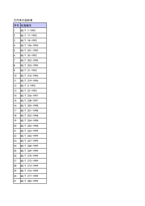
131 132 133 134 135 136 137 138 139 140 141 142 143 144 145 146 147 148 149 150 151 152 153 154 155 156 157 158 159 160 161 162 163
QC/T 508-1999 QC/T 509-1999 QC/T 510-1999 QC/T 511-1999 QC/T 512-1999 QC/T 513-1999 QC/T 515-2000 QC/T 516-1999 QC/T 517-1999 QC/T 5-1992 QC/T 520-1999 QC/T 521-1999 QC/T 527-1999 QC/T 540-1999 QC/T 541-1999 QC/T 542-1999 QC/T 543-1999 QC/T 544-2000 QC/T 551-1999 QC/T 55-1993 QC/T 552-1999 QC/T 555-2000 QC/T 556-1999 QC/T 558-1999 QC/T 56-1993 QC/T 570-1999 QC/T 571-1999 QC/T 572-1999 QC/T 573-1999 QC/T 574-1999 QC/T 575-1999 QC/T 583-1999 QC/T 584-1999
263 264 265 266 267 268 269 79 280 281 282 283 284 285 286 287 288 289 290 291 292 293 294 295
QC/T 232-1997 QC/T 233-1997 QC/T 234-1997 QC/T 237-1997 QC/T 239-1997 QC/T 240-1997 QC/T 241-1997 QC/T 24-1992 QC/T 245-2002 QC/T 246-1997 QC/T 247-2002 QC/T 253-1998 QC/T 256-1998 QC/T 258-1998 QC/T 259-1998 QC/T 262-1999 QC/T 271-1999 QC/T 279-1999 QC/T 284-1999 QC/T 287-1999 QC/T 29015-1991 QC/T 29018-1991 QC/T 29032-1991 QC/T 29033-1991 QC/T 29035-1991 QC/T 29061-1992 QC/T 29063-1992 QC/T 29078-1992 QC/T 29082-1992 QC/T 29089-1992 QC/T 29090-1992 QC/T 29096-1992 QC/T 29097-1992
康普型号
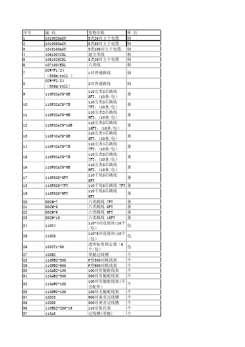
SC多模连接器 72口光纤配线架 机架式光纤配线架 机架式光纤配线架 600A系列支架 STII单模光纤连接器 6口ST耦合器面板 (不含耦合器,12个/ 包) ST单模耦合器 24口LC双工空面板 光纤夹 固线器 光线衰减测试仪 光纤耗材 光纤耗材 788H1替换头 五对打线工具 光纤耗材 挑线勾 单对打线工具(含手 柄及刀头) 单对打线工具手柄 单对打线工具刀头 光纤耗材 小型光纤工具( ST SC LC 多模/单模连 接) 光纤耗材 光纤工具(STⅡ,ST Ⅱ+,SC连接) 环氧胶水 OSP缓冲套管零件箱 (光纤消耗品附件) 光纤梳理器
货物名称 3类25对主干电缆 3类50对主干电缆 3类100对主干电缆 超五类线 5类25对主干电缆 六类线 1对普通跳线 2对普通跳线 110五类2芯跳线 5FT,(10条/包) 110五类2芯跳线 7FT,(10条/包) 110五类2芯跳线 9FT,(10条/包) 110五类2芯跳线 15FT,(10条/包) 110五类4芯跳线 5FT,(10条/包) 110五类4芯跳线 7FT,(10条/包) 110五类8芯跳线 7FT,(10条/包) 110五类8芯跳线 9FT,(10条/包) 110千兆8芯跳线 5FT 110千兆8芯跳线 7FT 110千兆8芯跳线 9FT 六类跳线 7FT 六类跳线 5FT 六类跳线 9FT 六类跳线 15FT 110-4对连接块(10个 /包) 110-5对连接块(10个 /包) 透明标签固定器(6 个/包) 带腿过线槽 P型300对跳线架 P型900对跳线架 100对有腿配线架 300对有腿配线架 100对有腿配线架(不 含配件) 100对无腿配线架 900对垂直过线槽 300对垂直过线槽 110安装托架 过线槽(带腿)
单 位 轴 轴 轴 箱 轴 箱 轴 轴 条 条 条 条 条 条 条 条 条 条 条 条 条 条 条 包 包 包 个 个 个 个 个 个 个 个 个 个 个
PCS-9705_ABC_说明书

我们定期仔细检查本文档中的内容,在后续版本中会有必要的修正。 资料相关,请联系: 但不可避免会有一些错误之处,欢迎提出改进的意见。 电话:025-87178185、传真:025-8718208 我们保留在不事先通知的情况下进行技术改进的权利。 电子信箱:nr_techsupport@ 南京南瑞继保电气有限公司 公司地址:中国南京江宁区苏源大道 69 号 邮编 211102 公司网址:
ii
南京南瑞继保电气有限公司
PCS-9705 系列测控装置
目录
前言.................................................................................................................................................... i 目录.................................................................................................................................................. iii 第 1 章 概述...................................................................................................................................... 1 1.1 应用范围 ............................................................................................................................. 1 1.2 功能配置 ............................................................................................................................. 2 1.3 性能特征 ............................................................................................................................. 3 1.4 订货选型 ............................................................................................................................. 3 1.5 产品执行标准 ...................................................................................................................... 3 第 2 章 技术参数 .............................................................................................................................. 5 2.1 电气参数 ............................................................................................................................. 5 2.1.1 交流电流 ................................................................................................................... 5 2.1.2 交流电压 ................................................................................................................... 5 2.1.3 直流电源 ................................................................................................................... 5 2.1.4 传感器输入 ............................................................................................................... 5 2.1.5 RTD 测温参数 ........................................................................................................... 6 2.1.6 传感器输出 ............................................................................................................... 6 2.1.7 开关量输入 ............................................................................................................... 6 2.1.8 开关量输出 ............................................................................................................... 6 2.2 机械特性 ............................................................................................................................. 6 2.3 环境条件参数 ...................................................................................................................... 7 2.4 通讯接口参数 ...................................................................................................................... 7 2.4.1 EIA-485 接口............................................................................................................. 7 2.4.2 以太网接口 ............................................................................................................... 7 2.4.3 光纤接口 ................................................................................................................... 7 2.4.4 对时接口 ................................................................................................................... 8 2.5 型式试验参数 ...................................................................................................................... 8 2.5.1 环境试验 ................................................................................................................... 8 2.5.2 机械试验 ................................................................................................................... 8
中兴S330硬件手册及应用
资料名称
产品版本
V1.2
您单位安装该设备的时间
ZXMP S330(V1.2)基于 SDH 的多业务节点设备 硬件手册
资料版本
20060325-R1.0
为了能够及时与您联系,请填写以下有关您的信息
姓名
单位名称
邮编
单位地址
电话
好
较好
一般
较差
差
总体满意
工作指导
您对本资料 的评价
查阅方便 内容正确 内容完整
声明
本资料著作权属中兴通讯股份有限公司所有。未经著作权人书面许可,任何单位或 个人不得以任何方式摘录、复制或翻译。
侵权必究。
和
是中兴通讯股份有限公司的注册商标。中兴通讯产品的名称和标志是
中兴通讯的专有标志或注册商标。在本手册中提及的其他产品或公司的名称可能是其各
自所有者的商标或商名。在未经中兴通讯或第三方商标或商名所有者事先书面同意的情
资料名称产品版本v12您单位安装该设备的时间zxmps330v12基于sdh的多业务节点设备硬件手册资料版本20060325r10为了能够及时与您联系请填写以下有关您的信息姓名邮编电话总体满意工作指导您对本资料的评价查阅方便内容正确内容完整结构合理图表说明通俗易懂内容结构内容详细您对本资料的改进建议内容深度表达简洁增加图形增加实例增加faq其他您对中兴通讯用户资料的其他建议单位名称单位地址较好一般详细说明较差差email好前言手册说明内容介绍本手册适用于unitranszxmps330v12基于sdh的多业务节点设备以下简称zxmps330
3. 《Unitrans ZXMP S330(V1.2)基于 SDH 的多业务节点设备 安装手册》 介绍设备的工程安装步骤,包括安装准备、硬件安装、线缆布放、安装检 查、设备上下电的具体操作。
G1000使用说明

g1000技术参数基本特性支持egprs900和gprs1800双频支持数字语音短消息和传真提供sim应用工具射频特性频率范围双频gprs900mhzdcs1800mhz动态范围104dbmfer05动态范围25dbmfer05闭环功控范围eighthdown24dbm闭环功控范围eighthup24dbm闭环功控范围fulldown24dbm闭环功控范围fullup24dbm闭环功控范围halfdown24dbm闭环功控范围halfup24dbm闭环功控范围quarterdown24dbm闭环功控范围quarterup24dbm波形质量0944开环功控范围254895dbm开环功控范围65895dbm开环功控范围9352095dbm频率误差df300hz国爵电子
G1000 硬件接口说明 .................................................................................................................................................................................................... 4
V1.00
UNI800 称重仪表手册
2
UNI800 使用说明书
目录
用前须知: ...................................................................................................................................................................1
2 技术参数...............................................................................................................................................................7
UNI800 使用说明书
1
用前须知:
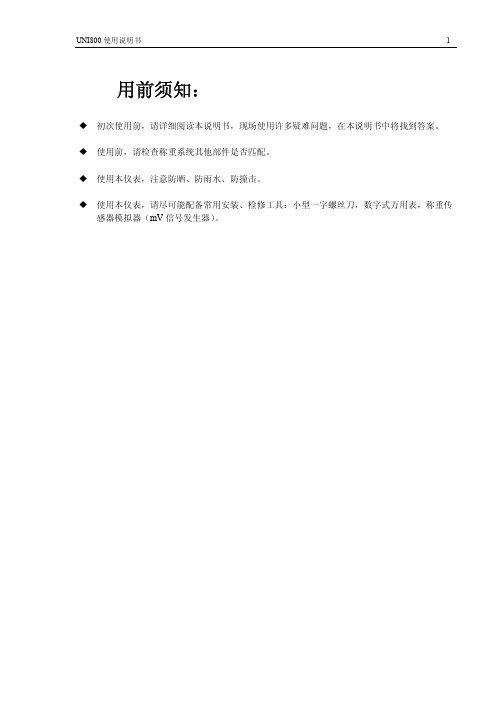
初次使用前,请详细阅读本说明书,现场使用许多疑难问题,在本说明书中将找到答案。 使用前,请检查称重系统其他部件是否匹配。 使用本仪表,注意防晒、防雨水、防撞击。 使用本仪表,请尽可能配备常用安装、检修工具:小型一字螺丝刀,数字式万用表,称重传 感器模拟器(mV 信号发生器)。
5 功能设置.............................................................................................................................................................14
1 概述.......................................................................................................................................................................5
2000汽车标准汇编目录

GB/T1332-1991 QC/T29020-1991 QC/T256-1998 QC/T257-1998 QC/T75-1998 QC/T76.1-1993 QC/T76.2-1993 QC/T76.3-1993 QC/T76.4-1993 QC/T76.5-1993 QC/T76.6-1993 QC/T76.7-1993 QC/T76.8-1993 QC/T76.9-1993 QC/T76.10-1993 QC/T76.11-1993 QC/T202-1995 QC/T250-1998 QC/T203-1995 GB/T12478-1990 GB/T12480-1990 GB/T11382-1989 QC/T29037-1991 QC/T29022-1991 QC/T29021-1991 QC/T271-1999 GB/T12675-1990 GB/T15087-1994 GB/T15088-1994 QCn29008.10-1991 QCn29008.11-1991 QCn29008.12-1991 QCn29008.13-1991 QC/T29056-1992
2000汽车标准汇编 第四卷 传动 制动 悬架
标准号 QC/T465-1999 QC/T470-1999 QC/T580-1999 GB/T13051-1991 QC/T29063-1992 QC/T568-1999 QC/T291-1999 QC/T292-1999 GB/T5727-1985 QC/T463-1999 QC/T29033-1991 QC/T557-1999 GB/T5728-1985 QC/T25-1992 QC/T27-1992 GB/T5764-1998 GB/T5333-1985 QC/T534-1999 QC/T533-1999 QC/T494-1999 QC/T483-1999 QC/T513-1999 QC/T294-1999 QC/T293-1999 QC/T29082-1992 QC/T523-1999 QC/T319-1999 QC/T460-1999 QC/T461-1999 GB5620.1-1985 GB5620.2-1985 GB13594-1992
超同步45P5GH1B说明书

GH DRIVERCTB资料编号:Z L-14-808-I B C NB E I J I N GC T B S E R V O C O.,L T D.GH DRIVER使用说明书交流伺服驱动器型号:BKSC-□□□□GHX400V级 1.5~315KW (2.5~460KVA)请将此使用说明书,交给最终用户,并妥善保存CTB TECHNOLOGY北京超同步伺服股份有限公司序 言感谢您惠购北京超同步伺服股份有限公司生产的GH系列交流伺服驱动器。
GH系列交流伺服驱动器是北京超同步伺服股份有限公司研制、开发生产的高品质、多功能、低噪音的交流伺服驱动器。
G H系列交流伺服驱动器是交流感应电机(I M)及交流永磁同步电机(PM)的交流伺服驱动器,可对各种交流伺服电机的位置、转速、加速度和输出转矩方便地进行控制,G H系列交流伺服驱动器采用双32位C P U,配置丰富的控制功能模块,可以实现各种机床的控制功能。
标配的控制接口可以和国内外各种数控系统方便地连接,使数控系统的功能得以充分地发挥。
配置G H系列交流伺服驱动器的机床,其力矩特性、加减速特性、精度特性以及效率特性都将表现非凡,并可以轻松地实现准停、C轴、刚性攻丝、电子换挡、多轴同步等功能。
G H系列交流伺服驱动器,可广泛应用于数控铣床、立式加工中心、卧式加工中心、数控镗床、数控车床、立车、重型卧车、龙门机床等产品的驱动,是各种机床动力轴的首选驱动产品。
在使用G H系列交流伺服驱动器之前,请您仔细阅读该手册,以保证正确使用。
错误使用可能造成驱动器运行不正常、发生故障或降低使用寿命,乃至发生人身伤害事故。
因此使用前应反复阅读本说明书,严格按说明使用。
本手册为随机发送的附件,务必请您使用后妥善保管,以备日后对驱动器进行检修和维护时使用。
01本说明书中与安全有关的内容,使用了下述符号,标注了安全符号的语句,所叙述的都是重要内容,请一定要遵守。
如果未按安全内容要求,使用该产品可能会造成产品使用不正常,甚至损坏产品,严重的可能会引起危险、造成人身伤亡。
- 1、下载文档前请自行甄别文档内容的完整性,平台不提供额外的编辑、内容补充、找答案等附加服务。
- 2、"仅部分预览"的文档,不可在线预览部分如存在完整性等问题,可反馈申请退款(可完整预览的文档不适用该条件!)。
- 3、如文档侵犯您的权益,请联系客服反馈,我们会尽快为您处理(人工客服工作时间:9:00-18:30)。
QUENCHARC
.850" Min.
.25" Max.
d
S Typ.
Capacitance Range: Voltage Range: Capacitance Tolerance: Resistor Tolerance: Resistor Values: Operating Temperature Range : Construction: Dielectric Withstand Voltage: DC Life Test:
"ARCING", "SPARKING", and "TRANSIENTS" often cause premature failures in relays, switches, thyristors, triacs, contactors, and related products. QUENCHARC extends operating life when properly selected and applied.
分销商库存信息:
CORNELL-DUBILIER 104M06QC100 104M06QC150 104MACQRL150 104M06QC47 504M02QA220 105M02QB47 104M06QC22 504M02QA100
Radial Metallized Polyester RC Network for Transient Suppression
QUENCHARC
Type Q/QRL (Quencharc® ) Arc Suppressor/Snubber Network
QUENCHARC Arc Suppressor Snubber Network
0.10 µF, 0.05 µF, 1.0 µF 200 Vdc/125 Vac, 60 Hz and 600 Vdc/250 Vac, 60 Hz ±20% ±10% 22, 47, 100, 150, 220 ohms –55 ºC to +85 ºC at full rated voltage Metallized polyester in series with a carbon composition resistor 1.6 x DC rated voltage @ +25 ºC 125% of rated voltage for a period of 500 hours at 85 ºC with capacitance change ≤5% and DF ≤ original limits Long Term Stability: The capacitance shall not change more than 2% when stored at ambient temperature and humidity for a period of two years or less.
Highlights
♦ ♦ ♦ ♦ ♦ ♦ ♦ ♦
Outline Dimensions
L Max.
Specifications
Noise and arc suppression RC Snubber Network Relay contact protection Noise reduction on controllers and drives EMI/RFI reduction Type QRL - UL/CSA verison Other ratings available by special request Coated with flame retardant epoxy
RoHS Compliant
200 Vdc / 125 Vac
600 Vdc / 250 Vac
UL/CSA Recognized Across-the-Line Application 104MACQRL150 0.10
Type QRL 125 Vac
Complies with UL1414/CSA-C22.2 No. 1)
Ratings
Catalog Part Number 504M02QA100 504M02QA220 105M02QB47 104M06QC22 104M06QC47 104M06QC100 104M06QC150 Cap (µF) 0.50 0.50 1.00 0.10 0.10 0.10 0.10 Ohms Watts ±10% 1/2 1/2 1/2 1/2 1/2 1/2 1/2 1/2 100 220 47 22 47 100 150 150
Type QRL: UL File No. E33628, CSA File No. LR32208
CDE Cornell Dubilier • 1605 E. Rodney French Blvd. • New Bedford, MA 02744 • Phone: (508)996-8561 • Fax: (508)996-3830 • /
Resistor Inches L Max 1.08 1.08 1.45 1.08 1.08 1.08 1.08 1.08 T Max 0.37 0.37 0.39 0.39 0.39 0.39 0.39 0.44 H Max 0.64 0.64 0.66 0.66 0.66 0.66 0.66 0.66 S Typ. 0.82 0.82 1.20 0.82 0.82 0.82 0.82 0.82 Ød 0.032 0.032 0.032 0.032 0.032 0.032 0.032 0.032 L Max 27.4 27.4 36.8 27.4 27.4 27.4 27.4 27.4 T Max 9.4 9.4 9.9 9.9 9.9 9.9 9.9 11.2 Millimeters H Max 16.3 16.3 16.8 16.8 16.8 16.8 16.8 16.8 S Typ. 20.8 20.8 30.5 20.8 20.8 20.8 20.8 20.8 Ød 0.8 0.8 0.8 0.8 0.8 0.8 0.8 0.8
