EFLC150P72中文资料
千伏表
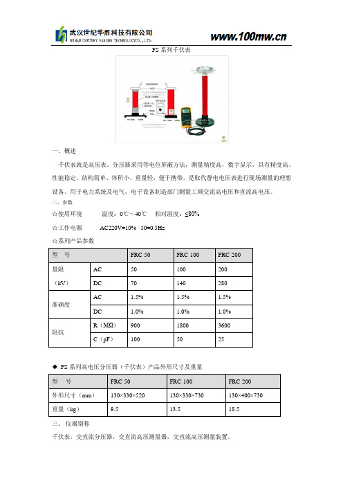
FS 系列千伏表
一、概述
千伏表就是高压表。
分压器采用等电位屏蔽方法,测量精度高,数字显示,具有精度高、性能稳定,结构简单、体积小,重量轻,便于携带,是取代静电电压表进行现场测量的理想设备。
用于电力系统及电气、电子设备制造部门测量工频交流高电压和直流高电压。
二、参数
☆使用环境 温度:0℃~40℃ 相对湿度:≤80% ☆工作电源 AC220V±10% 50±0.5Hz ☆系列产品参数
◆ FS 系列高电压分压器(千伏表)产品外形尺寸及重量 三、 仪器别称
千伏表,交直流分压器,交直流高压测量器,交直流高压测量装置。
Televac MP7ER FR双反向磁漏电子说明书
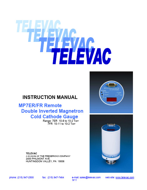
INSTRUCTION MANUAL MP7ER/FR RemoteDouble Inverted Magnetron Cold Cathode GaugeRange: 7ER 10-8 to 10-2 Torr7FR 10-11 to 10-2 TorrTELEVACA DIVISION OF THE FREDERICKS COMPANY2400 PHILMONT AVE.HUNTINGDON VALLEY, PA 19006PARTS LISTDescription and Instrument OperationThe MP7ER/FR series Remote Module provides a compact stand-alone measurement solution for applications that do not require traditional panel-mounted instrument readouts. These modules can provide local readout and control or can be interfaced directly with a PLC, chart recorder, or data acquisition system. The MP7ER/FR series of instruments use the time proven reliable and rugged TELEVAC 7ER/FR Sensor, which can be changed in seconds. These instruments operate from low voltage DC and are easily integrated into the largest process system with a minimal effort. Likewise, the MP7ER/FR Remote Gauge can be used as a small stand-alone vacuum measurement solution.Features» Wide range 10-2 to 10-11 Torr» Fast restart at high vacuum» No x-ray limit» Reduced external magnetic field» Compact design» Rugged/durable» No-filament burnout»No degassing required» Long life» Cleanable sensor (7ER)START BY READING THESE IMPORTANT SAFETY INSTRUCTIONS AND NOTES collected here for your convenience and repeated with additional information at appropriate points in these instructionsIn these instructions the word “product” refers to the MP7ER/FR and all of its approved parts and accessories.NOTE: These instructions do not and cannot provide for every contingency that may arise in connection with the installation, operation, or maintenance of this product. Should you require further assistance; please contact Televac at the address on the title page of this manual.This product has been designed and tested to offer reasonably safe service provided in it’s installed, operated and serviced in strict accordance with these safety instructions.These safety precautions must be observed during all phases of operation, installation, and service of this product. Failure to comply with these precautions or with specific warnings elsewhere in this manual violates safety standards of design, manufacture, and intended use of the instrument. Televac disclaims all liability for the customer’s failure to comply with these requirements.√ READ Instructions – Read all safety and operating instructions before operating the product. √ RETAIN instructions – Retain the Safety and Operating Instructions for future reference. √ HEED warnings – Adhere to all warnings on the product and in the operating instructions. √ FOLLOW instructions – Follow all operating and maintenance instructions.√ ACCESORIES – Do not use accessories not recommended in this manual as they may require a technician to restore the product to its normal operation.CHAPTER 3Principles of Sensor OperationDouble Inverted MagnetronCold Cathode GaugeThe cold cathode gauge is a high vacuum sensor that measures pressure by ionizing the residual gases in a magnetron discharge. The body of the gauge serves as a cathode, and is at ground potential. The anode operates at voltages up to 4000 volts. The permanent magnet traps electrons in the gauge to sustain the discharge at very low pressure. This gauge is sensitive to gas type. Because of the relative ruggedness of this gauge and since it has no filament to burn out, it is often used in applications where hot cathode gauges are not reliable.SENSOR OPERATION AND INSTALLATION1.0 Connect the gauge to the vacuum system, (can be connected in any position, but mounting withthe vacuum port facing down eliminates any chance of particles entering into the gauge).2.0 Assure that there are no leaks.3.0 Apply 24 DC volt power between pin #4 (+) and #2 (-). Monitor the signal output with a digital voltmeter between pin # 3 (+) and pin # 7. The display will show “OFF” and the signal output will be between 10.5 volts and 14.5 volts.4.0 The gauge is activated by grounding the wire from pin # 1 of the connector and may be operatedover any vacuum range, however, the following cautions.4.1 Activate the gauge only at pressures below 10-2 Torr. Continuous operation above thisrange will result in build up of contaminants inside the gauge and will produce errors inreading. In addition, at even higher pressures the gauge may falsely indicate lowerpressures by having passed beyond the peak of its curve.4.2 Initial activation of the gauge at pressures below 10-6 Torr may exhibit a delay inproviding an accurate reading of pressure until the electrical discharge within the tubehas established itself. This initial delay increases significantly at even lower pressures.Once established the discharge within the tube is maintained over the entire range. Avery rough estimate of start time can be calculated as T, sec = 1/pressure in µTorr.5.0 While the pressure is above the range of the gauge it will display “HI” and the signal output will bejust above the highest reading. If, on the other hand the pressure is below the lower gauge limit, the display will display “LO” and the signal output will remain at its lowest value.6.0 The trip pressure for the setpoint relay can be displayed by pressing the “Display Setpoint”button. It can also be read as a voltage – anytime – on the wire pin # 9 of the connector. Thedisplay will show the setpoint pressure as a blinking number (to distinguish it from a pressurereading) until the button is again pressed or it times out automatically after 60 seconds. Thesetpoint pressure can be changed only during the blinking display by means of the labeledadjustment screw. The new value is retained in memory and the corresponding new voltage isprovided at the setpoint terminal on the connector and is scaled in the same way as the signaloutput.SENSOR OPERATION AND INSTALLATION (cont.)M P 7F R lo g 10-110123456789101.00E -111.00E -101.00E -091.00E -081.00E -071.00E -061.00E -051.00E -041.00E -031.00E -02P R E S S U R E (T O R R )V O L T A G ERecorder Outputs“HI”9.210.2Maintenance1.0 1.1 1.2 1.3 1.42.02.2 2.3 2.4 Blast the2.5 After cleaning, blow out any residual glass beads or dust with dry air.2.6 Rinse with alcohol, followed with a rinse of de-ionized water. 2.7 Dry anode assembly and the body in a clean oven @ ~ 200° F.2.8 Re-grease the “O” ring with Apiezon L or M Grease. (A vacuum approved grease).DO NOT APPLY EXCESS GREASE. “O” ring should be shiny. 2.9 Install “O” ring in body..2.10 Replace the anode assembly in the body after the “O” ring has been installed.2.11 Screw the cap on and hand tighten.CHAPTER 6TELEVACCHAPTER 8CHAPTER 7 3.1 Without removing the sensor from the vacuum system, separate the electronic block from the sensor as described in Section 1.0 (Disassembling the 7ER/7FR ). 3.2 After separating the electronics from the sensor, but before disassembling of the sensor for cleaning, use a marker to mark the orientation and positions of the magnets relative to each other and relative to the stainless steel sensor tube. These are aligned at the factory for optimum performance of the sensor. When reassembling after cleaning, reassemble I reverse order with the magnets in their original respective locations and like pole surfaces facing each other (N to N, S to S). 3.3 Holding the magnets, use a 1/32” Allen wrench to remove three setscrews on the top aluminum holding ring. 3.4 Slide away the magnet’s washers and aluminum spacers from the tube’s body. Do not remove the lower aluminum holding ring (one that is closest to the flange). 3.5 Bake out the sensor using heat tape, blanket or other means with temperature controls. Temperature on the gauge’s surface should not exceed 350°C. NOTE : if the bake out temperature does not exceed 180°C for 2 hours, the sensor could be baked out with the magnets in place. 3.6 After cooling the sensor down to room temperature, re-assemble with the magnets in their original respective locations and like pole surfaces facing each other (N to N, S to S). 3.7 Put the electronic block onto the sensor and secure it with flat socket screw. CalibrationAll instrumentation is calibrated at the factory. No further calibration at the customer’s facility should be required, even if the gauge tube is replaced. For a reliable recalibration at a later date, it is necessary to have a reference standard vacuum system whose pressure is known to be accurate. For such a calibration, the instrument and sensor tube should be returned to the factory for re-certification. However, if the vacuum calibration verification must be done at the customer’s facility, a knowledgeable electronics technician trained in vacuum calibration should operate equipment of certifiable accuracy. Troubleshooting1.0 If display consistently displays “HI”, the pressure may be above the gauge upper limit (1 x 10⁻² TORR) units to the gauge or there may be a leak locally. Check the integrity of the vacuum connection and, if the 7E sensor is used, check the o-ring seal on the sensor tube.2.0 If the display constantly reads “LO”, the sensor may have become inoperative. Check for correct reassembly after bake out.3.0 If the display continues to read “LO” or “HI” after completing step 1.0 or 2.0, the sensor may be contaminated. Contamination can prevent the sensor from properly discharging (reference chapter 4, paragraph4.0 of this manual for information on operation of the sensor). To clean the sensor, refer to chapter 6, paragraph 2.0 of this manual. NOTE: If, after doing some or all of the above, the unit is still inoperative, return to the factory for repair.SpecificationsMeasurement Range RangeOutput Options1. Log 10 -10 to 10-2 Torr MP7ER: 10-2 TO 10-8 TORR2. Linear 10-8 to 10-3 Torr MP7FR 10-2 TO 10-11 TORR3. Log 2 X 10-11 to 10-2 TorrAccuracy Mounting Orientation+/-0.2 of decade of reading NoneInput Voltage/Power Ion ControlRequired +24 V DC @ 250 mA Ion ON/OFF Control is included Power ON Indicator LED is includedSetpoint Relay Adjustment PotentiometerForm C Contact SetpointOperating Temperature Calibration Medium+ 15 to 50C Dry Air or NitrogenSensor Material Overpressure ToleranceStainless Steel (Type 304) 150 PSIUnpacking and InspectionBefore each unit is installed or operated, a quick inspection should be performed and the following noted:a. damage to the unit (scratches, nicks, dents, cracks, etc.)b. missing: screws, switches or switch hardwarec. broken barrier strips, etc.d. broken or loose components within instrumentShould any of the above problems be encountered, contact the factory immediately. Any unauthorized repairs will void the warranty.CHAPTER 12Warranty informationThe Televac division warrants instruments and components to be free of defects in material and workmanship for a period of one year after the date of shipment unless otherwise specified in the quotation pr product literature. No salesman, Representative or agent of the Fredericks Company, or its divisions is authorized to give any guarantee or warranty or make any representation in addition or contrary to those stated herein.Other than those expressly stated herein, there are no other warranties of any kind, express or implied and specially excluded but not by way of limitation, are the implied warranties of fitness for a particular purpose and merchantability. It is understood and agreed the seller’s liability whether in contract, in tort, under any warranty, in negligence or otherwise shall not exceed the return of the amount of the purchase price paid by the purchases and under no circumstances shall seller be liable for special, indirect, incidental or consequential damages. The price stated for the equipment is a consideration in limiting seller’s liability. No action regardless of form, arising out of transactions of this agreement may be brought by purchase more than one year after the cause of action has accrued, seller’s maximum liability shall not exceed and buyer’s remedy is limited to either (1) repair or replacement.。
奥特维操作说明书

全自动光伏串焊机产品手册(Vol.2)
操作说明书
Operator Manual
无锡奥特维科技有限公司
Wuxi Autowell Technology Co., Ltd.
版 本 号:2.32 发布日期:2013 年 12 月
本手册为奥特维公司提供给客户使用的机器随机手册,部分内容涉及奥特维公 司技术秘密,未经奥特维公司书面同意,任何人不得向第三方复制或分发本手册的 部分或全部内容,如有违反,奥特维公司有权追究其法律责任。
目录
1 生产准备 ......................................................................................................................................................................1 1.1 生产准备流程 ...................................................................................................................................................1 1.2 开机前检查 .......................................................................................................................................................1 1.2 通电及生产准备 ..............................................................................................................2
TCL150DA2-W中文资料
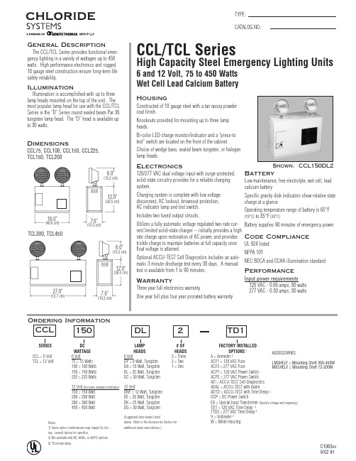
ACCESSORIESLMSHELF = Mounting Shelf 300-450W MXSHELF = Mounting Shelf 72-200WOrdering InformationSERIES DC WATTAGE HEADS HEADS OPTIONS 1CCL = 6 Volt 6 Volt6 Volt3 = Three A = Ammeter 2TCL = 12 Volt75 = 75 Watts DY = 8 Watt, Tungsten 2 = Two ACF1 = 120 VAC Fuse 100 = 100 Watts DA = 18 Watt, Tungsten 1 = OneACF2 = 277 VAC Fuse 150 = 150 Watts DL = 25 Watt, Tungsten ACP1 = 120 VAC Power Switch 225 = 225 WattsDC = 30 Watt, Tungsten ACP2 = 277 VAC Power Switch AD = ACCU-TEST Self-Diagnostics 12 Volt (Includes standard voltmeter)12 VoltADAL = ACCU-TEST with Alarm150 = 150 Watt DNY = 12 Watt, Tungsten ADTD = ACCU-TEST with Time Delay 3200 = 200 Watt DE = 28 Watt, Tungsten DCP = DC Power Switch300 = 300 Watt DK = 25 Watt, Tungsten EX = Special Input Transformer (Specify voltage and frequency)450 = 450 WattDG = 30 Watt, TungstenTD1 = 120 VAC Time Delay 3TTD2 = 277 VAC Time Delay 3(Suggested lamp heads listedV = Voltmeter 2above. Refer to the Accessories Section for W = White Housingadditional lamp head choices.)CCL15016.0”(40.6 cm)TCL300, TCL4506.0”(15.2 cm)7.6”(19.3 cm)12.0”(30.5 cm)27.0”(12.7 cm)6.0”(15.2 cm)7.6”(19.3 cm)12.0”(30.5 cm)Notes:1) Some option combinations may impact UL list-ing. consult factory for specifics.2) Not available witj AD, ADAL, or ADTD options.3) 15 minute delay.元器件交易网Housing18 gauge steel housing with a tan epoxy powder coat finish.Knockouts provided for mounting up to three lamp heads.The suggested lamp head is the “D” Series round sealed beam Par 36 tungsten. To order lamp heads other than the suggested “D” head, refer to Chloride Accessories Section..Suggested SpecificationFurnish and install Chloride Systems emergency lighting unit model ________. The unit shall be constructed to meet Underwriter’s Laboratories, Inc. Standard #924and the National Electrical Code (NEC).INSTALLATION AND OPERATION -Unit shall be easily field connected to a 120 or 277 VAC, 60 hertz, unswitched power source. Installation must comply with the NEC as well as other applicable codes. Upon utility power failure or brownout, the unit shall automatically transfer to battery power and maintain the required illumina-tion level for a minimum period of 90 minutes. Upon restoration of utility power, the charger shall restore the battery to full charge within UL 924 requirements follow-ing a rated discharge of not more than 90 minutes.CHARGER -Product shall utilize a fully automatic, voltage regulated, two-rate current limited solid-state charger. The charging system shall maintain the battery at full capacity without the need for periodic exercising or equalization. The following features shall be standard: Low voltage disconnect (LVD), brownout protection and AC lockout.BATTERY -The battery shall be a low maintenance, free electrolyte, wet cell, lead calcium battery. The lead calcium battery shall provide trouble-free operation in temperatures up to 85°F (30°C).HOUSING -The unit housing shall be constructed of 18 gauge steel with a tan epoxy powder coat finish.Chloride SystemsISO8C1063R49/02 IH272 West Stag Park Service Road •Burgaw NC 28425Telephone: (910) 259 1000 •Facsimile: (800) 258 Lamp Head Photometrics(For DL, suggested head for CCL)(For DK, suggested head for TCL)Vertical203050100Up 2010feet 010Down 20.2.1406070.31.5Horizontal203050100Left 2010feet 010Right 20.2.1406070.31.5203050100Up 2010feet 010Down 20Photometric No. 3406070801.3.2.1.5Horizontal203050100Left 3010feet 01020Right 301.3.2.120.540607080。
pic16c72中文资料

PIC16C73 通信波特率为 9600bps;通信采用查询方式,差错控制采用奇偶校验法;数据的 帻格式为 1 位起止位、8 位数据位、1 位奇偶位、1 位停止位;双方设置的握手信号如下:
“FFH”:为 PC 机请求接收信号;
“01H”:为 PC 机接收信号完毕;
b.PIC16C73 与红外线遥控器的通信协议
PIC16C71 单片机按键换醒 CPU 源程序 ; p=pic16c71,xt=40000hz LIST P=16c71 ; Z EQU 2 RBPU EQU 7 TEMP EQU 10H OPTIONREG EQU 1H F EQU 1 PORT_B EQU 06H ; INCLUDE <P16c71.INC> LIST ; ORG 0 ;复位地址 GOTO START ; ORG 4 ;中断向量
电子发烧友 电子技术论坛
SCI 利用 RC6 和 RC7 两个引脚来作为通信线的二线制串行通信接口。它们可被定义为三种 方式:全双工异步方式、半双工同步主控方式和半双工同步从动方式。
SIC 部件含有两个 8 位的可读写状态和控制寄存器,分别为发送和控制寄存器 TXSTA、接 收和控制寄存器 RCSTA。
RC0~RC7:复用引脚,为 C 口双向数据信号线,C 口引脚均为多功能复用引脚。
RC0/T1OS0/T1CK1 可选择 TMR1 振荡器输出或 TMR1 时钟输入;
RC1/T1OS1/CCP2 可作为 TMR1 振荡器输入或捕捉器 2 输入/比较器输出/PWH2 输出;
电子发烧友 电子技术论坛
d.片内器件模块
●有 3 个定时/计数器和 3 个双向 I/O 口。
●含有 16 位捕捉/比较/PWM 模块。其中捕捉器的最大分辨率为 12.5ns;而比较器的最大分 辨率为 200ns;PWM 的分辨率为 10 位。
EFKA控制箱参数项中文简单翻译

F-161 1=逆时针方向 F-162 电子夹线器全功率保持时间 F-163 电子夹线器的夹紧力度 F-164 电子夹线器全功率释放时间 F-165 电子夹线器的释放力度 F-170 调节参考位置 1=(设定针的最低位)停针位置和开始剪线位置 F-171 1A=关闭剪线功能位置 2=开始松线功能位置 2A=设定针的最高位置 用V810/V820面板测试输入/输出信号 01=倒回针 02=胎压脚 03=剪线 04=拨线 05=大小针码替换 06=松线 07=减低线张力 08=机针冷却 F-173 09=马达转动 10=最高压脚行程 12=机针上下位指示灯 13=大针码 14=夹线器 15=HP指示灯 16=右方底线监测指示灯 20=左方底线监测指示灯 21=手轮反转 23=手动倒回针指示灯 F-174 调较电眼位置 F-176 查看上次服务以后到现在的使用小时数/视软件版本有可能是F-177 F-178 语言选择
F-101 始缝倒回针时,启动针码调整延迟时间(起针夹线器) F-102 始缝倒回针时,关闭针码调整延迟时间(起针夹线器) F-103 终缝倒回针时,启动针码调整延迟时间(起针夹线器) F-104 终缝倒回针时,关闭针码调整延迟时间(起针夹线器) F-110 定针速度设定 F-111 最高速度设定 F-112 始缝倒回针速度设定 F-113 终缝倒回针速度设定 F-114 光电感应器感应后的车缝速度 F-115 慢针起缝速度 F-116 剪线速度设定 F-117 压脚最高抬升的车缝速度 F-118 启动数针功能以后的转速/看F-141和F-142的模式 转速等级 F-119 1=直线型 2=轻微渐进式 3=大渐进式 F-120 速度控制机针冷却,但超过设定速度以后,启动机针冷却装置(F-185=3) F-121 最高车缝速度 F-123 始缝倒回针同步时间 F-124 终缝倒回针同步速度 F-125 开始倒回针速度2(F-284打开) F-126 结束倒回针速度2(F-284打开) 声音信号设置(底线倒计数报警声音) 0=关闭 F-127 1=达到设置针数以后,发出声音并一直延续到按下复原键 2=达到设置针数后,马达会停顿一下,等车缝结束以后报警,一直到按下复位键 3=达到设置针数以后,马达会停顿一下,并且开始报警5次,等车缝结束以后长响,按复位停 止 F-128 光电感应器感应后的启动延时(F-129打开) F-129 光电感应器遮挡后缝纫机自动启动(F-132打开) F-130 光电感应器针织布料过滤功能 电眼感应启动方式 F-131
飞鸟科技 FP2 系列产品参数表说明书

0.5A (12-24V DC), 0.1A (5V DC) 0.1A (12-24V DC), 50mA (5V DC) 0.1A (12-24V DC), 50mA (5V DC)
FP2-Y16P FP2-Y32P FP2-Y64P
DC input, Transistor Input 32 points
Note: Please refer to “FPΣ Product Types” for FP Memory Loader.
Backplane
Part number AFP2207 AFP5208 AFP5209 AIC50020 AIC52000
Product name
FP2 Backplane
AFP25005 AFP25007 AFP25009 AFP25012 AFP25014 AFP25011MH AFP25010EH AFP2510 AFP2512
Product name
Specification
Product number Part number
FP2 Power supply unit
Not available
note 2)
note 3)
Available
AvailableFP2-CBiblioteka FP2-C1D FP2-C1SL
Standard type CPU unit FPSH CPU unit with IC memory card interface
CPU unit with IC memory card interface
Product types
CPU units (Built-in RAM)
Product name
东芝VFP7系列变频器中文说明书

务请接好地线,否则会在故障或漏电时引发触电或火灾事故。
2
TOSHIBA
危险
禁止接触
禁止
请勿接触变频调速器的散热风扇或放电电阻器,否则会引起高温和烫伤。
应使用与电源电压及三相感应电机的规格相匹配的变频调速器,否则不仅电机无法正确运 转,而且可能会导致变频调速器或电机过热或烧毁等重大事故。
东芝(中国)有限公司上海事务所
地址:上海市浦东新区银城东路 101 号 邮政编码:200120
电话:(021)-6841-5666(代表)
传真:(021)-6841-1161
东芝(中国)有限公司广州事务所
地址:广州环市东路 403 号广州国际电子大厦 1201-1202 邮政编码:510015 电话:(020)-8732-2646 传真:(020)-8732-2651
图标的意义
图标
意义 表示禁止事项(不允许做的事情)。 具体内容由图标中间或旁边的图文表示。 表示强制事项(必须做的事情)。 具体内容由图标中间或旁边的图文表示。
g 用户使用须知
用户选购的变频调速器用于一般工业用三相感应电动机的变速运转。
安全注意事项
t 在因变频调速器故障或工作错误可威胁生命或危害人体的设备(核动力控制设备、宇航设备、 交通工具用设备、各种安定设备等)中不可使用本变频调速器。如需要作特殊用途,请事先 问询本公司的经销负责人。
-对安装厂家的要求- 请注意务必把本使用说明书交到变频调速器的实际使用者手中。
株式会社 东芝
总公司 日本国东京都港区芝浦 1 丁目 1 番 1 号
邮政编码:105-0081 电话:03-3457-4880 传真:03-5444-9268
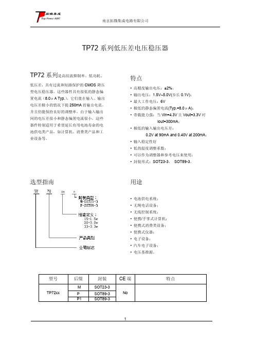
tp72
45
短路电流
Ishort
Vin=Vout(T)+1.5V Vout=Vss
25
过流保护电流
I limit
200
单位
V mA mV mV mV μA %/V
dB mA mA
3
南京拓微集成电路有限公司
TP7228
(Vin=Vout+1V,Cin=Cout=1u,Ta=25OC 除特别指定)
特性
符号
条件
最小值 典型值 最大值
X 0.98 100
VOUT(T) (Note 1)
X 1.02
10
180
360
静态电流
ISS
VIN=Vout+1V
7
电源电压调整率
∆VOUT ∆VIN •VOUT
IOUT =10mA Vout+1V ≤VIN≤5V
0.1
纹波抑制比
PSRR
Vin= [Vout+1]V +1Vp-pAC IOUT =10mA,f=1kHz
用途
• 电池供电系统; • 无绳电话设备; • 无线控制系统; • 便携/手掌式计算机; • 便携式消费类设备; • 便携式仪器; • 电子设备; • 汽车电子设备; • 电压基准源。
型号
TP72xx
后缀
M P P1
封装
SOT23-3 SOT89-3 SOT89-3
CE 端
No
1
特点
引脚排列图
南京拓微集成电路有限公司
南京拓微集成电路有限公司
TP72 系列低压差电压稳压器
TP72 系列是高纹波抑制率、低功耗、
低压差,具有过流和短路保护的 CMOS 降压 型电压稳压器。这些器件具有很低的静态偏 置电流(8.0μA Typ.),它们能在输入、输出 电压差极小的情况下提 250mA 的输出电流, 并且仍能保持良好的调整率。由于输入输出 间的电压差很小和静态偏置电流很小,这些 器件特别适用于希望延长有用电池寿命的电 池供电类产品,如计算机、消费类产品和工 业设备等。
EntelliGuard 中文样本
S
N
1000
690
50
65
50
65
40
50
50
65
50
65
40
50
50
65
40
50
105 143
20000
12500
10000
GG13 H 3,4
1250 12
1000 750
B ● 1250 85 65 65 35 85 65 65 35 65 50 187
50 35 20
E
1000
690
85 85 85
●
●
●
●
●
●
●
●
●
●
●
●
●
●
●
●
GJ10
S
N
3.4
1000 1000
12
690 690
B
●
1000
50
65
40
50
88.2 143
20000
12500
10000
M 3.4 1250 12 1000 750 B ● 1000 85 50 187 20000 10000 10000
GJ13
S
N
3.4
1000 1000
442
442
442
442
442
442
442
442
342
432
342
432
342
432
342
432
442
562
442
562
442
562
442
562
328
328
常州艾兰电气科技有限公司 弧压调高AL1002 系统说明书

数控弧压高度控制器
型号:AL1002
本控制器是一个闭环PWM控制系统,适合等离子切割机的割据高度自动控制,国产进口等离子都可以适配,本控制器采用100:1的分压板。
一、 技术参数:
输入电源:DC24V ,5A 输出功率:100W
控制电机:24V永磁直流电机 弧压检测:30V-350V
调整精度:可调 外形尺寸:145x105x25
二、接线示意图
三、 装箱单
序号 名称 数量
1 弧压高度控制板 1
2 隔离分压板 1
3 1K电位器 1
5 数显表头 1
6 使用说明书 1
产品质保说明:
本产品提供一年质保,终身成本维修。
下列情况,不属于服务范围:
1)不符合保修规定,产品编号不符,或缺失。
2)由于环境,及使用不当,未经我公司同意擅自维修造成损坏。
有疑问,请联系:0519‐83265602/5702
134****5692
常州艾兰电气科技有限公司。
74LVC1G157单片2输入多路选择器产品数据手册说明书

74LVC1G157Single 2-input multiplexerRev. 9 — 8 October 2019Product data sheet1. General descriptionThe 74LVC1G157 is a single 2-input multiplexer which select data from two data inputs (I0 and I1)under control of a common data select input (S). The state of the common data select inputdetermines the particular register from which the data comes. The output (Y) presents the selecteddata in the true (non-inverted) form.Inputs can be driven from either 3.3 V or 5 V devices. This feature allows the use of these devicesas translators in mixed 3.3 V and 5 V applications.This device is fully specified for partial power-down applications using I OFF. The I OFF circuitrydisables the output, preventing the damaging backflow current through the device when it ispowered down.Schmitt-trigger action at all inputs makes the circuit highly tolerant to slower input rise andfall times.2. Features and benefits•Wide supply voltage range from 1.65 V to 5.5 V•High noise immunity•Complies with JEDEC standard:•JESD8-7 (1.65 V to 1.95 V)•JESD8-5 (2.3 V to 2.7 V)•JESD8B/JESD36 (2.7 V to 3.6 V)•±24 mA output drive (V CC = 3.0 V)•CMOS low power consumption•Latch-up performance exceeds 250 mA•Direct interface with TTL levels•Inputs accept voltages up to 5 V•ESD protection:•HBM JESD22-A114F exceeds 2000 V•MM JESD22-A115-A exceeds 200 V•Multiple package options•Specified from -40 °C to +85 °C and -40 °C to +125 °C3. Ordering information4. Marking[1]The pin 1 indicator is located on the lower left corner of the device, below the marking code.5. Functional diagram6. Pinning information6.1. Pinning74LVC1G157I1SGND I0Y001aac6561236V CC54Fig. 5.Pin configuration SOT363 (SC-88) and SOT457 (SC-74)74LVC1G157GND 001aac657I1I0V CCSYT ransparent top view231546Fig. 6.Pin configuration SOT886 (XSON6)74LVC1G157GND 001aaf545I1I0V CC S YT ransparent top view231546Fig. 7.Pin configurationSOT891, SOT1115 and SOT1202 (XSON6)6.2. Pin description7. Functional descriptionTable 4. Function tableH = HIGH voltage level; L = LOW voltage level; X = don’t care.8. Limiting valuesTable 5. Limiting valuesIn accordance with the Absolute Maximum Rating System (IEC 60134). Voltages are referenced to GND (ground = 0 V).[1]The input and output voltage ratings may be exceeded if the input and output current ratings are observed.[2]For SOT363 (TSSOP6) packages: P tot derates linearly with 3.7 mW/K above 83 °C.For SOT457 (TSOP6) packages: P tot derates linearly with 4.1 mW/K above 89 °C.For SOT886 (XSON6) packages: P tot derates linearly with 3.3 mW/K above 74 °C.For SOT891 (XSON6) packages: P tot derates linearly with 3.3 mW/K above 74 °C.For SOT1115 (XSON6) packages: P tot derates linearly with 3.2 mW/K above 71 °C.For SOT1202 (XSON6) packages: P tot derates linearly with 3.3 mW/K above 74 °C.9. Recommended operating conditions10. Static characteristicsTable 7. Static characteristicsAt recommended operating conditions. Voltages are referenced to GND (ground = 0 V).[1]All typical values are measured at T amb = 25 °C.11. Dynamic characteristicsTable 8. Dynamic characteristicsVoltages are referenced to GND (ground = 0 V); for test circuit see Fig. 9.[1]Typical values are measured at T amb = 25 °C and V CC = 1.8 V, 2.5 V, 2.7 V, 3.3 V and 5.0 V respectively.[2]t pd is the same as t PLH and t PHL.[3]C PD is used to determine the dynamic power dissipation (P D in μW).P D = C PD x V CC2 x f i x N + Σ(C L x V CC2 x f o) where:f i = input frequency in MHz;f o = output frequency in MHz;C L = output load capacitance in pF;V CC = supply voltage in Volts;N = number of inputs switching;Σ(C L x V CC2 x f o) = sum of the outputs.11.1. Waveforms and test circuit12. Package outline13. Abbreviations14. Revision history15. Legal informationData sheet status[1]Please consult the most recently issued document before initiating orcompleting a design.[2]The term 'short data sheet' is explained in section "Definitions".[3]The product status of device(s) described in this document may havechanged since this document was published and may differ in case ofmultiple devices. The latest product status information is available onthe internet at https://.DefinitionsDraft — The document is a draft version only. The content is still under internal review and subject to formal approval, which may result in modifications or additions. Nexperia does not give any representations or warranties as to the accuracy or completeness of information included herein and shall have no liability for the consequences of use of such information. Short data sheet — A short data sheet is an extract from a full data sheet with the same product type number(s) and title. A short data sheet is intended for quick reference only and should not be relied upon to contain detailed and full information. For detailed and full information see the relevant full data sheet, which is available on request via the local Nexperia sales office. In case of any inconsistency or conflict with the short data sheet, the full data sheet shall prevail.Product specification — The information and data provided in a Product data sheet shall define the specification of the product as agreed between Nexperia and its customer, unless Nexperia and customer have explicitly agreed otherwise in writing. In no event however, shall an agreement be valid in which the Nexperia product is deemed to offer functions and qualities beyond those described in the Product data sheet.DisclaimersLimited warranty and liability — Information in this document is believedto be accurate and reliable. However, Nexperia does not give any representations or warranties, expressed or implied, as to the accuracyor completeness of such information and shall have no liability for the consequences of use of such information. Nexperia takes no responsibility for the content in this document if provided by an information source outside of Nexperia.In no event shall Nexperia be liable for any indirect, incidental, punitive, special or consequential damages (including - without limitation - lost profits, lost savings, business interruption, costs related to the removalor replacement of any products or rework charges) whether or not such damages are based on tort (including negligence), warranty, breach of contract or any other legal theory.Notwithstanding any damages that customer might incur for any reason whatsoever, Nexperia’s aggregate and cumulative liability towards customer for the products described herein shall be limited in accordance with the Terms and conditions of commercial sale of Nexperia.Right to make changes — Nexperia reserves the right to make changesto information published in this document, including without limitation specifications and product descriptions, at any time and without notice. This document supersedes and replaces all information supplied prior to the publication hereof.Suitability for use — Nexperia products are not designed, authorized or warranted to be suitable for use in life support, life-critical or safety-critical systems or equipment, nor in applications where failure or malfunctionof an Nexperia product can reasonably be expected to result in personal injury, death or severe property or environmental damage. Nexperia and its suppliers accept no liability for inclusion and/or use of Nexperia products in such equipment or applications and therefore such inclusion and/or use is at the customer’s own risk.Quick reference data — The Quick reference data is an extract of the product data given in the Limiting values and Characteristics sections of this document, and as such is not complete, exhaustive or legally binding. Applications — Applications that are described herein for any of these products are for illustrative purposes only. Nexperia makes no representation or warranty that such applications will be suitable for the specified use without further testing or modification.Customers are responsible for the design and operation of their applications and products using Nexperia products, and Nexperia accepts no liability for any assistance with applications or customer product design. It is customer’s sole responsibility to determine whether the Nexperia product is suitableand fit for the customer’s applications and products planned, as well asfor the planned application and use of customer’s third party customer(s). Customers should provide appropriate design and operating safeguards to minimize the risks associated with their applications and products. Nexperia does not accept any liability related to any default, damage, costs or problem which is based on any weakness or default in the customer’s applications or products, or the application or use by customer’s third party customer(s). Customer is responsible for doing all necessary testing for the customer’s applications and products using Nexperia products in order to avoid a default of the applications and the products or of the application or use by customer’s third party customer(s). Nexperia does not accept any liability in this respect.Limiting values — Stress above one or more limiting values (as defined in the Absolute Maximum Ratings System of IEC 60134) will cause permanent damage to the device. Limiting values are stress ratings only and (proper) operation of the device at these or any other conditions above thosegiven in the Recommended operating conditions section (if present) or the Characteristics sections of this document is not warranted. Constant or repeated exposure to limiting values will permanently and irreversibly affect the quality and reliability of the device.Terms and conditions of commercial sale — Nexperia products aresold subject to the general terms and conditions of commercial sale, as published at /profile/terms, unless otherwise agreed in a valid written individual agreement. In case an individual agreement is concluded only the terms and conditions of the respective agreement shall apply. Nexperia hereby expressly objects to applying the customer’s general terms and conditions with regard to the purchase of Nexperia products by customer.No offer to sell or license — Nothing in this document may be interpreted or construed as an offer to sell products that is open for acceptance or the grant, conveyance or implication of any license under any copyrights, patents or other industrial or intellectual property rights.Export control — This document as well as the item(s) described herein may be subject to export control regulations. Export might require a prior authorization from competent authorities.Non-automotive qualified products — Unless this data sheet expressly states that this specific Nexperia product is automotive qualified, the product is not suitable for automotive use. It is neither qualified nor tested in accordance with automotive testing or application requirements. Nexperia accepts no liability for inclusion and/or use of non-automotive qualified products in automotive equipment or applications.In the event that customer uses the product for design-in and use in automotive applications to automotive specifications and standards, customer (a) shall use the product without Nexperia’s warranty of the product for such automotive applications, use and specifications, and (b) whenever customer uses the product for automotive applications beyond Nexperia’s specifications such use shall be solely at customer’s own risk, and (c) customer fully indemnifies Nexperia for any liability, damages or failed product claims resulting from customer design and use of the product for automotive applications beyond Nexperia’s standard warranty and Nexperia’s product specifications.Translations — A non-English (translated) version of a document is for reference only. The English version shall prevail in case of any discrepancy between the translated and English versions.TrademarksNotice: All referenced brands, product names, service names and trademarks are the property of their respective owners.Contents1. General description (1)2. Features and benefits (1)3. Ordering information (2)4. Marking (2)5. Functional diagram (2)6. Pinning information (3)6.1. Pinning (3)6.2. Pin description (3)7. Functional description (3)8. Limiting values (4)9. Recommended operating conditions (4)10. Static characteristics (5)11. Dynamic characteristics (6)11.1. Waveforms and test circuit (7)12. Package outline (8)13. Abbreviations (14)14. Revision history (14)15. Legal information (15)© Nexperia B.V. 2019. All rights reservedFor more information, please visit: Forsalesofficeaddresses,pleasesendanemailto:*************************** Date of release: 8 October 2019Mouser ElectronicsAuthorized DistributorClick to View Pricing, Inventory, Delivery & Lifecycle Information:N experia:74LVC1G157GS,13274LVC1G157GN,13274LVC1G157GF,13274LVC1G157GM,11574LVC1G157GM,132 74LVC1G157GV,12574LVC1G157GW,125。
变频器的选择
• 2.滤波器 滤波器作用--阻止干扰信号沿电源线传播并
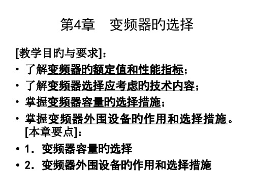
进行阻抗变换,使干扰信号不能经过地线 传播而被反射回干扰源。
在变频器输出端串联安装滤波器,能处理 电动机过热和噪声问题。
3.制动电阻
• b.由电网向变频器切换:在变频器运营中将电动机由电网向变频器切换将是对变频器作 一次破坏性旳试验,过大旳冲击电流将使变频器跳闸或损坏。假如电动机拖动旳负载 不允许忽然停车旳话,或者必须由定速运营转为调速运营时,能够这么操作:先将电 动机由电网切出,自由停车运营并延时l-2s,避开反电动势旳影响,在封锁变频器输出 旳情况下将电动机接到变频器上,跟踪电动机转速并以跟踪频率起动运营,冲击将会 较小。
冷切换:在变频器停车停电时进行切换,等切换完毕后再开机运营。
热切换:在变频器运营中进行带电切换。
其中,热切换又可分为:
(1) 硬切换:电动机在切换时要瞬时停电,因而可能会产生电流冲击。
• a.由变频器向电网切换:当电动机脱离变频器后,电动机定子绕组中旳电流及磁场立即 消失。因为电动机转子绕组是自成回路旳,由电磁原理,转子电流将受转子绕组旳自 感电动势阻止,而产生一种逐渐衰减旳过程,其初始值因转子转速及当初所带旳负载 而异,衰减过程时间一般为1~3 s。转子旳动能使转子继续旋转,在转子电流衰减为零 之前,旋转旳转子磁场在定子绕组中感生出感应电动势,将能量转移到定子中。定子 磁场能量以反电动势旳形式出现,其大小与转子电流有关,频率和相位与转子旳转速 、位置有关,这部分能量将伴随转子电流旳衰减而消失。若合闸时电源电压与定子感 应电动势旳相位差刚好为l80度,则将会产生比起动电流还要大旳冲击电流。矛盾集中 在切换时机旳选择上,而电动机转速降低和磁场衰减又与详细旳工况有关,较难把握 这是硬切换方式不可防止旳一种问题。
HCCCAP EDLCs 超级电容规格书说明书
HCCCAP EDLCsSPECIFICATION HCCCAP超级电容规格书【PRODUCT】产品:HCCCAP EDLCs【MODEL】型号:HCAP-D5R5474-F北京合众汇能科技有限公司HCC ENERGY TECH.Co.,LTD.TEL:+86-10-82897371email:*******************1.适用范围Scope本产品规格书对产品的性能,测试方法进行了规范,作为技术确认的参照。
数据参数仅作参考,不同批次与不同时间生产的实际产品参数可能会有所变化,以实际收到的产品为准,确切参数请及时向厂家核实。
This specification describes,the product property and test method,and should serve as the reference for technical assurance.These data is only for reference,actual product data in different batches and different times may vary,with the actual receipt of the product as a prospective,exact parameters,please promptly to the manufacturers to verify.2.一般特性General Specifications1)产品性能Features●高能量密度Ultra High Energy Density●长寿命Long Usage Life●高低温性能Excellent Performance at High and Low Temperatures●环保Environmental Friendly●免维护Maintenance Free2)产品应用范围Typical Applications●智能电网及其它配套设备Smart grid and other ancillary equipment●智能三表Intelligent Three-ammeters●集中器Concentrator●故障指示器Fault Indicator●混合动力汽车HEV/EV●太阳能/风能Solar/Wind energy●电机启动Motor drive●后备电源Memory Back up Batteries3)标准测试条件在标准大气压,温度5~35℃,相对湿度小于85%条件下进行测试;本规格书标准测试条件为标准大气压,温度25℃,相对湿度小于60%。
PowerBlock CPB150 150 Watt Stereo Guitar Amplifier

CPB150150 Watt Stereo Guitar AmplifierUser’s GuideTABLE OF CONTENTS:Introduction . . . . . . . . . . . . . . . . . . . . . . . . . . . . . . . . . .3The Front Panel . . . . . . . . . . . . . . . . . . . . . . . . . . . . . . .4The Rear Panel . . . . . . . . . . . . . . . . . . . . . . . . . . . . . . .5Using the Effects Loop Jack . . . . . . . . . . . . . . . . . . . . .6System Block Diagram . . . . . . . . . . . . . . . . . . . . . . . . .7T echnical Specifications . . . . . . . . . . . . . . . . .back cover2Congratulations and thank you for choosing another Crate first in guitar amplification:the Crate CPB150 PowerBlock TM 150 watt stereo guitar amplifier. The PowerBlock packs a lot of power and patching options into an amazingly compact and light weight package: 75 watts per channel @ 4 ohms, or 150 watts (mono) @ 8 ohms. With its switch-mode power supply and Class D power section, the PowerBlock offers lots of power, flexibility and tone, along with something no one thought you could get with such a powerful performer: extreme portability! (The PowerBlock even comes with its own padded travelling bag, which can be carried or slung on your shoulder, and even fits neatly into the semi-open back design of Crate’s GT112SL speaker cabinet.)The PowerBlock is housed in a light weight but virtually bullet proof anodized aluminum chassis which also cools the amplifier when in use. The unit is protected against speaker impedances below the recommended minimum, signal levels outside the proper operating range for the unit, and extreme unbalanced stereo conditions. The front panel features three bands of equalization, a gain and level control, and a headphone jack for private practice sessions. The rear panel of the PowerBlock is loaded with speaker output jacks (for stereo or mono use), a balanced XLR Line Out jack with level control, CD input jacks, and dual purpose line in / effects loop jacks for adding external effects or for patching an external line level signal into the PowerBlock. The PowerBlock also features speaker simulation circuitry for enhanced sound at each of the audio outputs.Designed by players and built for players, there’s really nothing else quite like your new Crate PowerBlock! (In order to get the most from your new PowerBlock, please read this user’s guide prior to its use.)3The Crate PowerBlock amplifier can drive up to four of our GT112SL cabinets, in stereo,or drive a single Celestion speaker-loaded GT112SL to the hilt in mono mode.412384567The Front Panel:1. INPUT: Use this 1/4” jack to connect your instrument to the amplifier by means of a 5. LOW:Use this control to adjust the low fre-quency output of the amplifier.13141516 The Rear Panel:9. SPEAKER OUTPUTS: Use these jacks to connect the amplifier to your speaker cabi-nets. Observe the wattage and impedance rat-ings adjacent to each jack. The Mono output is to be used when the Bridge Mono switch (#10) is depressed. The Right and Left jacks are to be used when running the amplifier in the stereo mode.NOTE:Do not operate the unit with stereo cabinets that have a common shield. Operating the unit with this type of cabinet will activate the protection circuitry caus-ing the unit to shut down.10. BRIDGE MONO:This switch, when depressed, sends the left channel to both power amplifiers and their outputs to the Mono Speaker Output jack (#9). When this switch is in the out position, the amplifier is in the stereo mode and the left and right signals are sent to the Left and Right Speaker Output jacks (#9).11. LEVEL:Use this control to adjust the level of the signal at the Line Out jack (#12).12. LINE OUT:Use this balanced XLR jack to send a line level signal to another amplifier, the house mixing board, or a recording console. (The signal at the Line Out jack is enhanced by the speaker simulator circuitry for superior sound.)13. CD INPUT:Use these RCA jacks to con-nect the outputs of a CD (or MP3)player to the amplifier. The level of the signal into these jacks must be controlled by the source.14. LINE IN RIGHT / LEFT/MONO / EFFECTS LOOP SND/RTN:Use these jacks to perform the following: (1) Send a line level signal into the amplifier for processing – for stereo sig-nals, use both jacks; for a mono signal, use the “Left/Mono” jack. (2) Connect an external effects device to the amplifier by means of a 1/4”T/R/S Y-cord inserted into the Effects Loop Snd/Rtn jack. (See page 6 for additional infor-mation.) These jacks are post eq, post Level.15. POWER:Use this switch to turn the ampli-fier on (top of the switch depressed) and off (bottom of the switch depressed).16. AC LINE IN: Connect the AC power cordsecurely into this jack.The grounded power cord should only be plugged into a grounded power outlet that meets all applicable electri-cal codes and is compatible with the voltage, power and frequency requirements stated on the rear panel. Do not attempt to defeat the safety ground connection!5Using the Effects Loop Jack:The Effects Loop Snd/Rtn jack allows for virtually noise free connection ofexternal effects. You will need a stereo-to-dual-mono 1/4” adapter asdescribed in the illustrations below. This T/R/S jack is wired as follows: tip= return, ring = send, sleeve = ground.67System Block Diagram:INPUT BRIDGE MONOOUTPUTSLEFTMONORIGHTLEFTRIGHTPREAMPSND/RTNOUTSPEAKER SIMLEFTSPEAKER SIM RIGHT++–Declaration of ConformityManufacturer ’s Name:SLM ElectronicsCorporate Headquarters:1901 Congressional Drive, St. Louis, Missouri 63146Primary Production Facility:700 Hwy 202 W, Yellville, Arkansas, 72687Product Type:Audio AmplifierProducts meet the regulations for compliance marking under:ETL standards UL6500, UL60065, or UL813CSA standards E60065 or C22.2 No.1-M90CE safety standard EN60065CE EMC standards EN55103 or EN55013 and EN61000C-tick designation Level 2, ABN #56748810738, ARBN# N222KETI standard K60065 (limited model approval)Compliance Support Contact: SLM Electronics, Attn: R&D Compliance Engineer1901 Congressional Drive, St Louis, Missouri, 63146 • Tel.: 314-569-0141, Fax: 314-569-0175*Please refer to Item 9, Speaker Outputs (page 5)CPB150TECHNICAL SPECIFICATIONS:Output Power Rating Mono 150W RMS @10% THD @ 8 ohms Stereo 75W RMS @10% THD per side @ 4 ohms Input ImpedanceInstrument700k ohm CD 22k ohm Line In22k ohmTotal System Gain (all controls @10)Instrument91dB CD 33dB Line34dBMaximum Input Signal Accepted 8 volts peak to peak Tone ControlsLow 20dB range @ 110Hz Mid 15dB range @ 1kHz High20dB range @ 10kHz Power Requirements120 VAC, 60Hz, 35VA 100/115VAC, 50/60Hz, 35VA 230VAC, 50/60Hz, 35VADimensions 3.2”H x 10” W x 5.6”D Weight4.6 lbs.The CPB150 is housed in an anodized aluminum chassis: occasionally wipe it clean with a lint-free cloth.Never spray cleaning agents onto the unit. Avoid abrasive cleansers which would damage the finish.Crate continually develops new products, as well as improves existing ones. For this reason, the specificationsand information in this manual are subject to change without notice.@2005 SLM Electronics, a division of St. Louis Music, Inc • 1400 Ferguson Avenue • St. Louis, MO 6313347-463-02 • 061305This equipment has been tested and found to comply with the limits for a Class B digital device, pursuant to part 15 of the FCC Rules. These limits are designed to provide reasonable protection against harmful interference in a residential installation. This equipment generates, uses and can radiate radio frequen-cy energy and, if not installed and used in accordance with the instructions, may cause harmful interfer-ence to radio communications. However, there is no guarantee that interference will not occur in a par-ticular installation. If this equipment does cause harmful interference to radio or television reception,which can be determined by turning the equipment off and on, the user is encouraged to try to correct the interference by one or more of the following measures:• Reorient or relocate the receiving antenna.• Increase the separation between the equipment and the receiver.• Connect the equipment into an outlet on a circuit different from that to which the receiver is connected.• Consult the dealer or an experienced radio/TV technician for help.Changes or modifications to this device not expressly approved by SLM Electronics could void the user’s authority to operate the equipment under FCC rules.。
DH72150资料
TUNING VARACTORSelection GuidePAGE SURFACE MOUNT SILICON ABRUPT TUNING VARACTOR1-32HIGH Q SILICON ABRUPT JUNCTION TUNING VARACTOR-VBR = 30 V1-34 -VBR = 45 V1-35 SILICON HYPERABRUPT JUNCTION TUNING VARACTOR1-36 MICROWAVE SILICON HYPERABRUPT JUNCTION TUNING VARACTOR1-39 A tuning varactor is a P-N diode that acts as a voltage controlled capacitor. These devices perform the same function as the familiar, bulky, air dielectric stacked capacitors featured in traditional broadcast band receivers.DescriptionThis series of silicon tuning varactors have an epitaxial mesa design with a high temperature passivation. This technology is used to produce abrupt tuning varactor in SOT23 package. This family is designed for a low cost medium to high volume market that may be supplied in tape and reel for automated pick and place assembly on surface mount circuit boards.ApplicationsThe DH71000 series abrupt tuning varactor are offered in a large selection of capacitance range. They provide the highest Q factor (low reverse series resistance) available for a 30 volts silicon device.Typical applications include low noise narrow and moderate frequency bandwidth applications (VCO mainly) from HF to Microwave frequencies (up to 3 GHz). Other applications are voltage tuned filters, phase shifters, delay line, etc.NOTE : Variation of the junction capacitance versus reverse voltage follows this equation:C j (V r) C j (0 V)1 + V rV r : Reversevoltage φ: Built-in potential .7V for Siγ: .5 for abrupt tuning varactor[ ]SOT23 SURFACE MOUNT SILICON ABRUPT TUNING VARACTORγ=Electrical characteristics at T a = +25°CReverse breakdown voltage, Vb = @10 µA: 30 V min.T emperature ranges:Operating junction (T j): -55°C to +125°C Storage:-65°C to +150°C Packages(1) Other configuration available on request.How to order?DH71010-51T3Diode type Package Conditioninginformation51: single SOT23T3: 3000 pieces53: dual common tape & reelcathode SOT23T10: 10000 pieces54: dual common tape & reelanode SOT23blank: bulk60: single SOD32370: dual SOT143V BR 30VThis series of high Q epi-junction microwave tuning varactors (30 V) incorporates a passivated mesa technology. It is well suited for frequency tuning applications up to Ku band.Description(1)Custom cases available on requestT emperature ranges:(2)Closer capacitance tolerances available on request Operating junction (T j ):-55°C to +150°C (3)C = C + C Storage:-65°C to +175°CThis series of high Q epi-junction microwave tuning varactors (45 V) incorporates a passivated mesa technology. It is well suited for frequency tuning applications up to X band.DescriptionV BR 45VPLASTIC PACKAGE, SURFACE MOUNT HYPERABRUPT TUNING VARACTORDescriptionThis series of silicon tuning varactors consists of hyperabrupt epitaxial devices. They incorporate a passivated mesa technology. T his family is designed for a low cost medium to high volume market that may be supplied in tape and reel for automated pick and place assembly on surface mount circuit boards. ApplicationThe DH76000 and DH77000 series hyperabrupt tuning varactor are offered in a large selection of capacitance range. They provide the highest Q factor (low reverse series resistance). Typical applications include low noise narrow and moderate frequency bandwidth applications (VCO mainly) from HF to Microwave frequencies (up to 3 GHz). Other applications are voltage tuned filters, phase shifters, delay lines...20 Volt hyperabrupt junction varactorsCharacteristics @ T a=+25°C T emperature ranges:Reverse breakdown voltage, Vb = 20 V min. @ 10 µA Operating junction (Tj) : -55°C to +125°C Reverse Current, Ir = 200 nA @ 16 V Storage : -55°C to +150°C12 Volt hyperabrupt junction varactorsCharacteristics @ T a=+25°C T emperature ranges:Reverse breakdown voltage, Vb = 12 V min. @ 10 µA Operating junction (Tj) : -55°C to +125°C Reverse Current, Ir = 200 nA @ 8 V Storage : -55°C to +150°CT ypical junction capacitance versus reverse voltageVR (V)V (V)C j (p F )Packages(1) Other configuration available on request.How to order?DH76150-51T3Diode type Package Conditioninginformation51: single SOT23T3: 3000 pieces53: dual common tape & reelcathode SOT23T10: 10000 pieces54: dual common tape & reelanode SOT23blank: bulk60: single SOD32370: dual SOT143HIGH Q SILICON HYPERABRUPT JUNCTION TUNING VARACTORDescriptionThis series of silicon tuning varactors consists of hyperabrupt epitaxial devices.They incorporate a passivated mesa technology. Packaged or chip devices are available for linear electronic tuning from VHF up to Ku band.Characteristics @ T a = +25°CReverse breakdown voltage, Vb = @ 10 µA:20 V min.Reverse current, Ir @ 16 V: 200 nA(1)Custom cases available on requestT emperature ranges:Operating junction (T j ):-55°C to +150°C Storage:-65°C to +150°CT ypical junction capacitance reverse voltage。
PHOENIX CONTACT 5孔绿色头部(PC 4 3-G-7,62)商品说明书
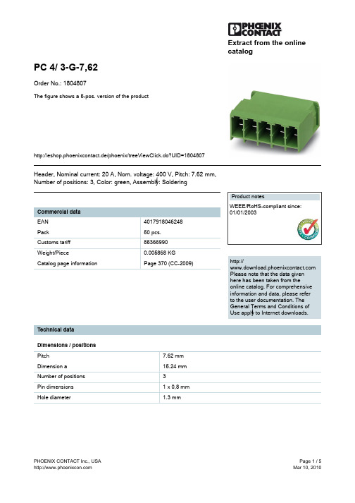
Extract from the onlinecatalogPC 4/ 3-G-7,62Order No.: 1804807The figure shows a 5-pos. version of the producthttp://eshop.phoenixcontact.de/phoenix/treeViewClick.do?UID=1804807Header, Nominal current: 20 A, Nom. voltage: 400 V, Pitch: 7.62 mm, Number of positions: 3, Color: green, Assembly: Solderinghttp://Please note that the data givenhere has been taken from theonline catalog. For comprehensiveinformation and data, please referto the user documentation. TheGeneral Terms and Conditions ofUse apply to Internet downloads. Technical dataDimensions / positionsPitch7.62 mmDimension a15.24 mmNumber of positions3Pin dimensions 1 x 0,8 mmHole diameter 1.3 mmTechnical dataInsulating material group IRated surge voltage (III/3) 6 kVRated surge voltage (III/2) 6 kVRated surge voltage (II/2) 6 kVRated voltage (III/2)630 VRated voltage (II/2)630 VConnection in acc. with standard EN-VDENominal current I N20 ANominal voltage U N400 VMaximum load current20 AInsulating material PAInflammability class acc. to UL 94V0Certificates / ApprovalsCertification BV, CSA, CUL, DNV, GL, GOST, LR, RS, ULCSANominal voltage U N300 VNominal current I N20 ACULNominal voltage U N300 VNominal current I N35 AULNominal voltage U N300 VNominal current I N35 AAccessoriesItem Designation DescriptionAssembly1827570BF-PC 4Mounting flange, is snapped onto the left and right of the headers,for screw connection with PC 4/...-STF-7.62Marking1051993B-STIFT Marker pen, for manual labeling of unprinted Zack strips, smear-proof and waterproof, line thickness 0.5 mm0804549SK 7,62/3,8:FORTL.ZAHLEN Marker card, printed horizontally, self-adhesive, 10-section markerstrip, 12 identical decades marked 1-10, 11-20 etc. up to 91-99,sufficient for 120 terminal blocks0805153SK 7,62/3,8:SO Marker card, special printing, self-adhesive, labeled acc. tocustomer requirements, 12 identical marker strips per card, max.25-position labeling per strip, color: white0803906SK U/3,8 WH:UNBEDRUCKT Unprinted marker cards, DIN A4 format, pitch as desired, self-adhesive, with 40 stamped marker strips, 185 mm strip length, canbe labeled with the CMS system or manually with the M-PENPlug/Adapter1600027CP-HCC 4Coding profile, Color: redAdditional productsItem Designation DescriptionGeneral1848902PC 4 HV/ 3-ST-7,62Plug component, Nominal current: 20 A, Nom. voltage: 800 V,Pitch: 7.62 mm, Number of positions: 3, Connection type: Screwconnection, Color: green1882382PC 4 HV/ 3-STF-7,62Plug component, Nominal current: 20 A, Nom. voltage: 800 V,Pitch: 7.62 mm, Number of positions: 3, Connection type: Screwconnection, Color: green1804917PC 4/ 3-ST-7,62Plug component, Nominal current: 20 A, Nom. voltage: 400 V,Pitch: 7.62 mm, Number of positions: 3, Connection type: Screwconnection, Color: green1828252PC 4/ 3-STF-7,62Plug component, Nominal current: 20 A, Nom. voltage: 400 V,Pitch: 7.62 mm, Number of positions: 3, Connection type: Screwconnection, Color: green1840188PCC 4/ 3-ST-7,62Plug component, Nominal current: 20 A, Nom. voltage: 400 V,Pitch: 7.62 mm, Number of positions: 3, Connection type: Crimpconnection, Color: greenDiagrams/DrawingsDrilling plan/solder pad geometryDiagramThe illustration shows the derating curve for plugs PC 5/...-ST-7,62 in combination with header PC 4/...-G-7,62. Dimensioned drawingAddressPHOENIX CONTACT Inc., USA586 Fulling Mill Road Middletown, PA 17057,USA Phone (800) 888-7388Fax (717) 944-1625© 2010 Phoenix Contact Technical modifications reserved;。
IP67防水pH计说明书

p age |4pH / mV / Temperature Best value for an IP67-rated waterproof pH meter • Large, three line LCD – View pH or mV measurement with temperature and % slope• Built-in memory function – Stores up to 150 measurements along with temperature• Auto buffer recognition – Automatically identifies USA, NIST or DIN buffer sets for rapid calibration• Power with AA batteries or use optional AC adapter for benchtop measurements• Calibration due alarm – Set a visible reminder when it is time to recalibrate the meterSpecification TableOrdering InformationpH / Ion / ORP / ºC / ºF pH / ORP / ºC / ºF pH / Ion / ORP / ºC / ºF pH / ORP / ºC / ºF Graphic LCD with backlight & extensive display Large LCD with dual display-2.000 to 20.000 pH0.1 / 0.01 / 0.001 pHpH / ORP /Ion / ºC / ºF pH / ORP / ºC / ºF pH / ORP / ºC pH / ORP /ºC / ºF pH / ORP / ºCIon / pH /ORP / ºC pH / ORP / ºC pH / ºCWaterproof, GLP, RS232C, IrDA, Ion, 0.001 pH Waterproof,GLP, RS232C,IrDA,0.001 pHWaterproof,GLP, RS232C,IrDA, 0.01 pHWaterproof,GLPWaterproofhandheldExpandedmemory,RS232CoutputStandardhandheldEconomicalIon, pH, ORPmeasurementEconomicalpH, ORPmeasurementEconomicalpHmeasurement>> Wastewater Treatment<< Aquaculture>> Food Processing << Cooling TowerspHTestr 30pHTestr 20EcoTestr pH 2pHTestr 10BNC pH Spear ORPTestr 10ORPTestr 10BNC pH / ºC / ºF pH ORP 0.01 resolution, temp. display 0.01 resolution 0.1 resolution BNC connection Open pore, spear tip Platinum band sensor BNC connection -1.00 to 15.00 pH -1.0 to 15.0 pH 0.0 to 14.0 pH -1.00 to 15.00 pH -999 to +1000 mV 0.01 pH 0.1 pH 0.01 pH 1 mV ±0.01 pH ±0.1 pH ±0.01 pH ±2 mV 1 manualAccurate, Convenient, and ReliableWelcome to Ohaus! With over 100 years of success in weighing products, now Ohaus is getting into more areas of laboratory products. We are proudly presenting STARTER series of pH meters and conductivity meters. With a clear focus on meeting our customers’ needs, Ohaus electrochemistry products are designed to provide a reliable, fast and easy solution for our customers with many unique and innovative features. Standard Features Include:● Well orgnized menu on white backlit LCD screen● pH Electrode Condition Icons give user information of the electrode condition● Date and Time display, with the most recent calibration data● Stand alone electrode arm, can be placed anywhere near the meter● 3-in-1 pH electrode/4-ring conductivity electrode● Auto buffer recognition, with 3-point calibration● Auto Functions: ATC, auto endpoint, auto self-diagnosis ● STARTER Series products are manufactured at ISO 9001 facilities, and meet CE requirements Our goal is to provide the best value in its class!STARTER Series pH & Conductivity ProductsSTARTER Series pH & Conductivity ProductsSTARTER 3000/2000STARTER 3000 and 2000 are both benchtop pH meters that can be used for a variety of measurement applications. They are accurate, fast, and easy.Other convenient features:●Well-organized menu in bright white backlit LCD●Auto/manual endpoint modes, can be switched to meet different test situations*Only available on STARTER 3000●*Date and Time DisplayAlso record the most recent calibration data● Electrode Condition Icon Shows electrode condition information●*Auto TemperatureCompensation (ATC)With 3-in-1 electrode to make accurate measurements●*Auto Buffer Recognition,3-point Calibration●Electrode ArmCan be placed anywhere near the meter●Auto Self-diagnosisDisplays error message, helps end-users find problemsSTARTER 300A portable pH meter that provides the best value in its class.Spec.STARTER 3000 STARTER 2000 STARTER 300Measurement Range 0.00...14.00 pH 0.00...14.00 pH 0.00...14.00 pH -1999...+1999mV -1600...+1600mV -1999...+1999mV-5 ˚C...105 ˚C -0 ˚C...100 ˚C Resolution 0.01 pH 0.01 pH 0.01 pH 1 mV 1 mV 1 mV0.1 ˚C -0.1 ˚C Error Limits/Accuracy ± 0.01 pH ± 0.05 pH ± 0.01 pH ± 1 mV ± 5 mV ± 1 mV± 0.5 ˚C-± 0.5 ˚CpH Calibration Up to 3 pointsUp to 2 pointsUp to 3 pointsCalibration Buffer 4 predefined buffer group4.01, 7.00, 10.01 predefined buffer 4 predefined buffer groupMemory1024 sets, most recent calibration data with date&time -30 sets, most recent calibration data Power/Battery 100-240V/50-60Hz, 9 V DC100-240V/50-60Hz, 9 V DC4 x AAA >500 hrsSize/Weight 160 W x 200 D x 65 H mm /0.65kg 150 W x 195 D x 60 H mm /0.55kg 90 W x 170 D x 35 H mm/0.18 kg Display White backlight liquid crystal White backlight liquid crystal Liquid crystalpH Input BNC, impedance >10e+12 Ω BNC, impedance >5x10e+11 Ω BNC, impedance >10e+12 ΩTemp InputCinch, NTC 30 kΩ - Cinch, NTC 30 kΩTemp CompensationATC or MTC MTCATC or MTC Temp Compensation Range 0 ˚C...100 ˚C 0 ˚C...60 ˚C 0 ˚C...100 ˚C IP Rating- - IP54Housing MaterialsABSABSABSSpecifications●Wrist WrapAdditional security during transport●Built-in Meter Stand For benchtop using●Electrode ClipCan be attached to either side of the meter●Integrated Labeling For quick product identification●Auto Buffer Recognition,3-point Calibration●ATC with 3-in-1 Electrode ●Auto Self-diagnosis, Auto/manual Endpoint Modes●Ergonomic and CompactDesignpH ElectrodesOHAUS offers a wide electrode portfolio to meet different pH measurment applications.ST310 3-in-1 refillable pH electrode, for general samplesST320 3-in-1 gel pH electrode, no need to refill reference electrolyte, for general samplesST210 2-in-1 refillable pH electrode, for general samplesST230 2-in-1 muddy sample pH elec-trode, for samples like juice, sauce, grape wine etc.STPURE 2-in-1 pure water pH electrode, for low ion concentration water such as distilled water, rain water, tap water etc.STTEMP30 temperature electrode with 30K thermistor, long life time, can work with 2-in-1 pH electrodeSTARTER 3000CSTARTER 300C●4-ring Conductivity ElectrodeGives more accurate results, comes with temperature sensor, ATC●White Backlit LCD ScreenBright and clear screen, well-organized menu●Auto/manual Endpoint ModesTwo modes can be switched for different situations●Auto Self-diagnosisGives error message, helps users troubleshoot●One-touch ConversionSwitch between conductivity and TDS value●4-ring Conductivity Electrode ●Ergonomic and Compact Design ●Built-in Meter Standing Feet ●Integrated Labeling Design ●One-touch ConversionSTARTER 3000C is bench meter for general conductivity or TDS measurement.STARTER 300C is portable meter used in the field, or as a benchtop奥豪斯始终致力于其产品功能的改进工作。
