USB3000H
USBCANFD-100U-mini产品用户手册说明书
USBCANFD-100U-miniUSBCANFD 系列CANFD 接口卡修订历史目录1.产品简介 (1)1.1产品概述 (1)1.2产品外观 (1)1.3功能特点 (1)1.4产品规格 (2)1.4.1电气参数 (2)1.4.2工作温度 (2)1.5机械安装尺寸 (2)1.6典型应用 (3)2.设备硬件接口说明 (4)2.1USB接口 (4)2.2CAN通讯接口 (4)2.3信号指示灯 (5)2.4系统连接 (5)3.驱动程序安装 (8)3.1Windows系统下安装驱动程序 (8)4.检查和维护 (11)5.装箱清单 (12)6. ZCANPRO软件使用指南 (13)6.1ZCANPRO软件简介 (13)6.2USBCANFD在ZCANPRO上使用指南 (13)7.免责声明 (14)1.产品简介1.1 产品概述USBCANFD-100U-mini是广州致远电子开发的一款便捷式、高性能CANFD接口卡,其兼容USB2.0总线规范,集成1路CANFD接口,CAN通道集成独立的电气隔离保护电路。
接口卡使PC通过USB端口连接至CAN(FD)网络,构成CAN(FD)-bus控制节点。
USBCANFD-100U-mini高性能CANFD接口卡是CAN(FD)-bus产品开发、CAN(FD)-bus 数据分析的强大工具;USBCANFD-100U-mini接口卡上自带电气隔离模块,使接口卡避免由于地环流的损坏,增强系统在恶劣环境中使用的可靠性。
USBCANFD-100U-mini高性能CAN 接口卡支持Win7/Win10等操作系统。
1.2 产品外观图1.1产品外观1.3 功能特点●USB接口符合USB2.0高速规范;●支持CAN2.0A、B协议,符合ISO11898-1规范;●集成1路CANFD接口;●兼容高速CAN和CANFD;●CANFD支持ISO标准、Non-ISO标准。
●CAN通讯波特率在40Kbps~1Mbps之间任意可编程;●CANFD波特率在1Mbps~5Mbps之间任意可编程;●单通道发送最高数据流量:3000帧/秒(远程帧、单帧发送);●单通道接收最高数据流量:10000帧/秒(远程帧);●每通道支持最高64条ID滤波;●每通道支持最高100条定时发送报文,定时精度可达500us;●内置120欧终端电阻,可由软件控制接入与断开;●支持USB总线电源供电;●支持ZCANPRO配套软件(支持Win7、Win10操作系统);●提供上位机二次开发接口函数。
联想dm3000h安装教程

联想dm3000h安装教程
1.首先,将联想DM3000H连接到电源并打开电源开关。
等待几分钟,直到系统启动完成。
2.接下来,您需要设置BIOS。
按下DEL键进入BIOS设置界面,然后按照屏幕上的提示进行设置。
在BIOS设置中,您需要选择正确的启动设备和语言选项。
3.然后,您需要安装操作系统。
您可以使用光盘或USB驱动器来安装操作系统。
如果您使用光盘,请将其插入光驱并按照屏幕上的提示进行操作。
如果您使用USB驱动器,请将其插入计算机并按照屏幕上的提示进行操作。
4.在安装操作系统时,您需要选择正确的分区和格式化选项。
请注意,格式化会删除所有数据,因此请确保备份重要文件。
5.安装完成后,您需要安装联想DM3000H的驱动程序和其他必要的软件。
您可以从联想官方网站下载这些软件。
6.最后,您需要配置联想DM3000H的网络连接和其他设置。
您可以按照屏幕上的提示进行操作,或者参考联想DM3000H的用户手册。
以上是联想DM3000H的安装教程。
请注意,在安装过程中可能会遇到一些问题,因此请务必仔细阅读用户手册并遵循屏幕上的提示。
如果您
遇到任何问题,请参考联想官方网站或联系联想客户支持。
华硕 M5A78L USB3 主板用户手册

或認可之配件所引起之故障與損壞。 D. 因用戶自行安裝軟件及設定不當所造成之使用問題及故障。 E. 計算機病毒所造成之問題及故障。 F. 本公司保修識別標籤撕毀或無法辨認,涂改保修服務卡或與產品不符。 G. 要求華碩提供軟件安裝服務(用戶需自行提供原版軟件)、軟件故障排除或清除密碼等。 H. 其它不正常使用所造成之問題及故障。 用戶手冊中所談論到的產品名稱僅做識別之用,而這些名稱可能是屬於其他公司的註冊商標 或是版權。 關於產品規格最新的升級信息請您到華碩的官方網站瀏覽或是直接與華碩公司聯絡。
usb3.0 hub方案
USB3.0 Hub方案概述USB(Universal Serial Bus,通用串行总线)是一种用于在计算机系统之间传输数据和供电的通用接口标准。
USB接口得到了广泛应用,如连接打印机、键盘、鼠标、摄像头、存储设备等。
随着需求的增加,USB集线器(Hub)变得不可或缺。
本文将介绍一种USB3.0集线器方案,以满足高速数据传输需求。
USB3.0技术概述USB3.0是USB接口的升级版本,提供更高的数据传输速度和更高的功率输出。
相对于USB2.0,USB3.0的主要改进有: - 更高的传输速度:USB3.0的传输速度最高可达到5 Gbit/s,比USB2.0的480 Mbit/s要快10倍。
- 增加带宽:USB3.0使用双向数据传输,在USB2.0的基础上新增了四条数据线,分别用于接收和发送数据。
- 更强大的供电能力:USB3.0接口提供更高的功率输出,最高可达到4.5 W。
USB3.0 Hub方案设计为了实现高速数据传输,USB3.0集线器需要具备以下关键特性: 1. 快速传输速度:支持USB3.0的5 Gbit/s传输速度。
2. 多口输出:提供多个USB接口,方便用户同时连接多个USB设备。
3. 适配器供电:为连接的USB设备提供稳定的电力。
4. 多系统兼容性:兼容与USB2.0和USB1.1设备的连接,并自动适配传输速度。
USB3.0集线器芯片选择选择一款适合的USB3.0集线器芯片对方案的成功至关重要。
以下是一些常见的USB3.0集线器芯片供参考: - 瑞萨电子(Renesas)的µPD720210:该芯片集成了USB3.0 Hub控制器和USB接口电路,支持4个USB3.0端口和电源管理功能。
- VIA Technologies的VL812:该芯片支持7个USB3.0端口,提供72 Mhz的内部晶振,并通过FIFO(先进先出)架构来提供高传输速度。
- Genesys Logic的GL3520:该芯片支持4个USB3.0端口,并具备多种保护功能,如过流保护、超过温度保护等。
科威尔 C3000H系列高性能可编程直流电源 产品用户手册说明书

高性能可编程直流电源C3000H系列产品用户手册型号:C3000H系列科威尔技术股份有限公司(KEWELL TECHNOLOGY CO.,LTD.)是一家专注于测试设备制造的高新技术企业,坚持自主创新,依托电力电子技术平台,融合软件仿真算法与测控技术,为众多行业提供专业、可靠、高性能测试电源和测试系统。
公司总部位于安徽合肥,在北京、上海、深圳、西安、南京共设立五个分公司。
目前产品主要应用于新能源发电、电动车辆、燃料电池及功率器件等工业领域。
公司注重研发团队的建设及技术创新,坚持“产、学、研”合作,自成立以来便长期与合肥工业大学开展多项校企合作,并设立“科威尔奖学金”;同时公司积极联合电源行业内公益组织在浙江大学、南京航空航天大学、华中科技大学、西安交通大学及西安理工大学等多所高校发放奖学助学金,助力电力电子学科未来电源精英人才建设。
“勇担当、敢创新、精益求精”是公司的核心价值观,科威尔致力成为全球领先的测试电源及系统供应商,为客户提供专业的产品和服务,让测试精准便捷。
如果您有关于我公司产品的任何问题请与我们联系,我们将非常乐意为您解答。
联系方式:地址:合肥市高新区大龙山路8号邮箱:******************.cn网址:科威尔技术股份有限公司版权所有(C)2020Copyright Kewell版本号:K-CPSC-3900112有限性本手册适用于C3000H系列高性能可编程直流电源产品。
法律声明此文档涉及科威尔技术股份有限公司的C3000H系列产品的专利及保密信息。
未经本公司许可,不得将本手册以复印、拍照、发布网上等形式流传。
本手册是针对C3000H系列产品的基本功能及特性进行说明,由于产品型号分类较多,未能对所有型号进行详细描述,或增加其他功能的特规机型,均不在此通用手册内进行说明,具体操作说明请参考随机发送的操作指南。
科威尔技术股份有限公司有权对本手册的细节内容进行修改。
质保服务■质保期本产品根据合同的规定以对其进行质量保证和售后维护■证据在质保期内,我公司要求客户出示购买产品的发票和日期。
MF833V USB Modem 快速入门指南说明书
MF833VUSB ModemQuick Start Guide ZTE CORPORATIONNO. 55, Hi-tech Road South, Shenzhen, P.R.ChinaLEGAL INFORMATIONCopyright © 2017 ZTE CORPORATION.All rights reserved.No part of this publication may be excerpted, reproduced, translated or utilized in any form or by any means, electronic or mechanical, including photocopying and microfilm, without the prior written permission of ZTE Corporation.The manual is published by ZTE Corporation. We reserve the right to make modifications on print errors or update specifications without prior notice.Version No. : R1.0Edition Time: April 13, 2017Manual No.:Getting to Know Your Your modem supports data an enabling you to communicate The following figure is only for 1. Modem cap 2. Front cover 3. Indicator light 4. USB connector 5. microSDHC™ card slot 6. micro-SIM card slotNOTE:microSDHC logoInstalling the micro-SIM 1. Press and push the front co NOTE:ur Modemata and SMS services through the mobile phon icate anytime and anywhere.nly for your reference. The actual product mayis a trademark of SD-3C, LLC.SIM Card and microSDHC Cardont cover and remove it.e phone network, may be different.Do not open the front cover ru2. Install a micro-SIM card to t WARNING!Your modem does not supp modem, do not use those card3. Install a microSDHC card to th ver rudely. Failing to do so may cause damage to d to the micro-SIM card slot.support SIM cards and nano-SIM cards. To av e cards or any card holders.d to the microSDHC card slot.ge to the front cover.avoid damage to the4. Slide the front cover gently baConnecting the Modem Insert the modem into you automatically detects and idetly back into place.dem to Your PCo your computer’s USB port securely. The nd identifies your modem and starts the installoperating system nstallation wizard.NOTE:If the system does not launc installation icon in My CompuAccessing the Internet After the modem is connected Internet in Automatic or ManModeAutomaticManualNOTE:To modify the parameters of yby visiting http://192.168.10Getting More HelpYou can get help by:●Sending an email to mob●Visiting www.ztedevice.launch installation automatically, you can doubomputer to install the software.netected to your computer successfully, you canManual mode. The default mode is AutomatOperationYour modem is connected to the Internetyou can surf on the Internet directly.1. Log in to the 4G Hostless Modem conf2. Select Network Settings > Connectioand then click Apply.3.Click to return to the home page,or .s of your modem, log in to the 4G Hostless Modem100.1.**************.cndouble-click the modemcan access theomatic.ernet automatically, andconfiguration page.ection Mode > Manual,page, and then clickModem configuration pageWarning and NoticeUsing Your Modem●If inadequately shielded, some electronic devices may be affected by theelectromagnetic interference caused by the modem, such as the electronic system of vehicles. Consult the manufacturers of such devices before using the modem if necessary.●Operating the modem may interfere with medical instruments such as hearing aidsand pacemakers. Always keep the modem more than 20 centimeters away from such medical instruments when your modem is turned on. Turn the modem off if necessary.Consult a physician or the manufacturers of medical instruments before using the modem if necessary.●Be aware of the usage limitation when using the modem at places such as oilwarehouses or chemical factories, where there are explosive gases or explosive products being processed. Turn off the modem if necessary.●Do not use electronic transmission devices in aircrafts, at petrol stations or inhospitals. Observe and obey all warning signs, and turn off the modem in these conditions.●Do not touch the inner antenna area unless it is necessary. Otherwise theperformance of the modern may be affected.●Keep the modem out of the reach of little children. The modem may cause an injury ifused as a toy.●When the modem is operating, do not touch the metallic parts. Failing to do so maycause burns.●Use original accessories or accessories that are authorized. Using any unauthorizedaccessories may affect the performance of the modem and violate the related national regulations about telecom terminals.●Avoid using the modem near or inside metallic structures or establishments that canemit electromagnetic waves, because signal reception may be affected.●The modem is not waterproof. Keep the modem dry and store it in a shady and coolplace.●Do not use the modem immediately after a sudden temperature change. In such case,dew may be generated inside and outside the modem, so do not use it until it becomes dry.●Handle the modem carefully. Do not drop, bend or strike it. Otherwise the modemmay be damaged.●Only qualified personnel can dismantle and repair the modem.●An operating temperature between -10°C and +55°C and a humidity between 5% and95% are recommended.Limited Warranty• This warranty does not apply to defects or errors in the product caused by:i. Reasonable abrasion.ii. End users’ failure to follow ZTE’s installation, operation or maintenance instructions or procedures.iii. End users’ mishandling, misuse, negligence, or improper installation, disassembly, storage, servicing or operation of the product.iv. Modifications or repairs not provided by ZTE or a ZTE-certified individual.v. Power failures, surges, fire, flood, accidents, and actions of third parties or other events outside ZTE’s reasonable control.vi. Usage of third-party products, or usage in conjunction with third-party products if such defects are due to the combined usage.vii. Any other cause beyond the range of normal usage intended for the product.End users have no right to reject or return the product, or receive a refund for the product from ZTE under the above-mentioned situations.This warranty is end users’ sole remedy and ZTE’s sole liability for defective or nonconforming items, and is in lieu of all other warranties, expressed, implied or statutory, including but not limited to the implied warranties of merchantability and fitness for a particular purpose, unless otherwise required under the mandatory provisions of the law.Limitation of LiabilityZTE shall not be liable for any loss of profits or indirect, special, incidental or consequential damages resulting from or arising out of or in connection with using of this product, no matter whether or not ZTE had been advised, knew or should have known of the possibility of such damages, including, but not limited to lost profits, interruption of business, cost of capital, cost of substitute facilities or product, or any downtime cost.FCC RegulationsThis device complies with part 15 of the FCC Rules. Operation is subject to the condition that this device does not cause harmful interference.This device has been tested and found to comply with the limits for a Class B digital device, pursuant to Part 15 of the FCC Rules. These limits are designed to provide reasonable protection against harmful interference in a residential installation. This equipment generates uses and can radiate radio frequency energy and, if not installed and used in accordance with the instructions, may cause harmful interference to radio communications. However, there is no guarantee that interference will not occur in a particular installation. If this equipment does cause harmful interference to radio or television reception, which can be determined by turning the equipment off and on, the user is encouraged to try to correct the interference by one or more of the following measures:●Reorient or relocate the receiving antenna.●Increase the separation between the equipment and receiver.●Connect the equipment into an outlet on a circuit different from that to which thereceiver is connected.●Consult the dealer or an experienced radio/TV technician for help.CAUTION:Changes or modifications not expressly approved by the party responsible for compliance could void the user’s authority to operate the equipment.FCC RF Exposure Information (SAR)This device is designed and manufactured not to exceed the emission limits for exposure to radio frequency (RF) energy set by the Federal Communications Commission of the United States.During SAR testing, this device is set to transmit at its highest certified power level in all tested frequency bands, and placed in positions that simulate RF exposure in usage against the head with no separation, and near the body with the separation of 5 mm. Although the SAR is determined at the highest certified power level, the actual SAR level of the device while operating can be well below the maximum value. This is because the device is designed to operate at multiple power levels so as to use only the power required to reach the network. In general, the closer you are to a wireless base station antenna, the lower the power output.The exposure standard for wireless devices employs a unit of measurement known as the Specific Absorption Rate, or SAR. The SAR limit set by the FCC is 1.6 W/kg.Tests for SAR are conducted using standard operating positions accepted by the FCC with the device transmitting at its highest certified power level in all tested frequency bands.The FCC has granted an Equipment Authorization for this model device with all reported SAR levels evaluated as in compliance with the FCC RF exposure guidelines. SAR information on this model device is on file with the FCC and can be found under the Display Grant section of /oet/ea/fccid after searching onFCC ID: SRQ-MF833V.For this device, the highest reported SAR value for usage near the body is 1.11 W/kg. While there may be differences between the SAR levels of various devices and at various positions, they all meet the government requirement.SAR compliance for body operation is based on a separation distance of 5 mm between the unit and the human body. Carry this device, at least 5 mm away from your body to ensure RF exposure level compliant or lower to the reported level. To support body operation, choose the belt clips or holsters that do not contain metallic components to maintain a separation of 5 mm between this device and your body.9IC CautionThis device complies with Industry Canada license-exempt RSS standard(s). Operation is subject to the following two conditions:(1) This device may not cause interference, and(2) This device must accept any interference, including interference that may cause undesired operation of the device.Le présent appareil est conforme aux CNR d'Industrie Canada applicables aux appareils radio exempts de licence. L'exploitation est autorisée aux deux conditions suivantes:(1) l'appareil ne doit pas produire de brouillage, et(2) l'utilisateur de l'appareil doit accepter tout brouillage radioélectrique subi, même si le brouillage est susceptible d'enThis Class B digital apparatus complies with Canadian ICES-003.Cet appareil numérique de la classe B est conforme àla norme NMB-003 du Canada. IC: 10719A-C561010。
英特尔 服务器主板 S3000AH 说明书
Consignes de sécurité
Lisez attention toutes les consignes de sécurité et les mises en garde indiquées dans ce document avant de suivre toute instruction. Consultez Intel Server Boards and Server Chassis Safety Information sur le Intel® Server Deployment Toolkit 2.0 CD ou bien rendez-vous sur le site /support/motherboards/server/sb/cs010770.htm.
英特尔 ® 服务器主板 S3000AH 用户指南
Hale Waihona Puke vvi英特尔 ® 服务器主板 S3000AH 用户指南
前言
关于本手册
感谢您购买和使用英特尔 ® 服务器主板 S3000AH。 本手册面向负责对该服务器主板进行故障排除、升级和修复的系统技术人员。本 文档概述了主板 / 机箱的功能、提供了附件或您可能需要的其他组件的列表、故障 排除信息以及有关如何在文档标题上添加和更换组件的说明。若要获取本手册的 最新版本,请访问 /support/cn/motherboards/server/S3000AH/
其他信息和软件
如果您需要有关本产品的更多信息,或有关本服务器主板可用附件的信息,请使 用以下资源。可从 /support/cn/motherboards/server/S3000AH/ 获得这些文件。 除非在下表中另有说明,否则,请在该 Web 页屏幕左侧的搜索栏中键入文档名称 或软件名称,然后选择搜索 “本产品”的选项。 表 1. 其他信息和软件
迈德斯MIDAS U-PHORIA UMC202HD 2x2,24位 192kHz USB音频接口说

Audiophile 2x2, 24-Bit/192 kHzUSB Audio Interface withMIDAS Mic Preamplifi ersThe incredible U-PH ORIA UMC202H Dbridges the gap between your creativity and your fans. This blazingly fast USB 2.0 studio in a box will have you recording your next masterpiece in minutes with all the connectivity required for your microphones, guitars, keyboards and even MIDI devices.Record the perfect vocal right to your computer-based DAW thanks to the 4 astonishingly pure, world-class MIDAS-designed mic preamps, which include +48 Volt phantom power for condenser microphones, all going through studio-grade 24-Bit/192 kHz converters for the best possible sound quality. Whether you’re a singer-songwriter, producer on the go, or just need a rock-solid interface for running backing tracks at a gig, the ultra-dependable U-PHORIA UMC202HD will help you shine in the digital domain.Studio in a Little Black Box When it’s time to make recording history on your Mac or Windows computer, plug in microphones, instruments or line level sources to the UMC202H D’s 2 combination XLR/T RS inputs for the ultimate in studio fl exibility! Connect and communicate with MIDI devices to add the benefi t of control surfaces to your studio workfl ow.#2x2 USB 2.0 audio interfacefor recording microphonesand instruments#Audiophile 24-Bit/192 kHz resolutionfor professional audio quality#Compatible with popularrecording software includingAvid Pro Tools*, Ableton Live*,Steinberg Cubase*, etc.#Streams 2 inputs / 2 outputs withultra-low latency to your computer,supporting Mac* OS X* andWindows XP* or higher# 2 state-of-the-art, MIDASdesigned Mic Preamplifi ers with+48 V phantom power#Zero-latency directmonitoring while recording#Powerful Phones output with Levelcontrol and Direct Monitor select#Status, Signal and Clip indicationsfor perfect overview#USB port for connection and power#Free audio recording,editing and podcasting softwareplus 150 instrument/eff ect plug-insdownloadable at #“Built-like-a-tank”, impact-resistantmetal chassis#3-Year Warranty Program**#Conceived and designed byBEHRINGER Germany*Mac and OS X are trademarks of Apple Inc. Windows XP is aregistered trademark of Microsoft Corporation in the United Statesand other countries. All third-party trademarks are the property ofAudiophile 2x2, 24-Bit/192 kHzUSB Audio Interface withMIDAS Mic Preamplifi ers192 kHz PrecisionYou take your tracks seriously, and the UMC202HD respects that, providing up to 192 kHz resolutionfor even the most demanding applications in music as well as video post production. Work withconfi dence and accuracy in your favorite recording software for professional results every time.MIDAS - The Legend in Sound QualityEver since its formation in the 1970s, MIDAS has had a long history of innovation and leadership in the world of audio mixing consoles. Employed by the most famous touring acts and installations world-wide, legendary MIDAS consoles such as the XL4 and Heritage H3000 quickly became industry standards.MIDAS has earned their impeccable reputation due to their no-compromise approach for audio and build quality and in particular for their Award-winning Mic Preamps which are considered by industry experts as the industry’s best sounding designs. Building on this legacy, the XL8 and PRO Series of Live Mixing Systems continue this great heritage of Award-winning audio quality.BEHRINGER is proud to incorporate a MIDAS designed mic preamp for the ultimate in high-quality audio reproduction in both live and studio environments. Find out more about MIDAS’ amazing legacy by visiting their extensive website .Audiophile 2x2, 24-Bit/192 kHzUSB Audio Interface withMIDAS Mic Preamplifi ers“Zero-Latency” MonitoringThe UMC202H D mix control allows zero-latency direct monitoring, which means musicians canexperience their performance clearly – with no delay or lag in the returning signal, resulting in abetter performance and recording. A powerful phones output has its own level control and MonitorA/B source select for DJ-style cueing. To make it a done-deal, we provide free audio recording,editing and podcasting software, plus 150 instrument / eff ects plug-ins – just a download away at.Getting ConnectedOn the rear panel of the UMC202HD, you’ll fi nd the USB 2.0 port for simple and easy connectionto your computer, along with plenty of analog playback options including ¼" TRS, RCA and XLR.The UMC202HD also features 2 analog Inserts for use with external eff ects such as compressors,gates and EQs, etc. Built-in MIDI I/O allows you to connect keyboards and all your favorite outboardMIDI hardware.Tracktion - Record, Edit, Mix and ShareTracktion is one of the world’s fastest and easiest Digital Audio Workstations (DAW) for composing,recording, editing, mixing and sharing your music with the world. Featuring a single-screeninterface, and pushing the envelope in design elegance, Tracktion brings together outstanding ProDAW features, such as dynamic automation, unlimited track count, MIDI recording and support forVST and AU plug-ins. This powerful music production software gives you all the tools of an entireprofessional-grade recording studio. Learning a DAW has never been easier, thanks to their vast andreadily available library of resources.As our way of saying “Thank You”, when you register your (insert the product name) at, we’ll reward you with a complimentary download code for the full versionof Tracktion 4. Recording and editing couldn’t be easier. To learn more about Tracktion, visit/support/videos.Audiophile 2x2, 24-Bit/192 kHzUSB Audio Interface withMIDAS Mic Preamplifi ersEverything You Need to Sound AmazingThe U-PHORIA UMC202HD is a powerful 2 input, 2 output USB recording interface featuring genuineMIDAS-designed mic preamps with exceptional 24-Bit/192 kHz high-resolution converters, designedto help your recordings and mixes sound their absolute best. Visit your local dealer or online resellerand fi nd out what a great addition to any studio or mobile recording rig it can be.You Are CoveredWe always strive to provide the best possible Customer Experience. Our products are made in ourown MUSIC Group factory using state-of-the-art automation, enhanced production workfl ows andquality assurance labs with the most sophisticated test equipment available in the world. As a result,we have one of the lowest product failure rates in the industry, and we confi dently back it up with agenerous 3-Year Warranty program.Audiophile 2x2, 24-Bit/192 kHz USB Audio Interface with MIDAS Mic Preamplifi ersFor service, support or more information contact the BEHRINGER location nearest you:EuropeM USIC Group Services UK Tel: +44 156 273 2290USA/Canada M USIC Group Services NV Inc.Tel: +1 702 800 8290Japan M USIC Group Services JP K.K.Tel.: +81 3 6231 0454Audiophile 2x2, 24-Bit/192 kHzUSB Audio Interface withMIDAS Mic Preamplifi ers。
普洛菲斯触摸屏,GP3000H系列(中文版)硬件手册
< 注意事项 >
将 GP 嵌入终端产品之前请明确以下几点: • GP 只能在室内使用。
*1 嵌入以下三个部件的系统符合 UL/c-UL 标准: • GP3000H
• GP3000H 直连电缆 ( 带接头 )
GP3000H-CBLHD-10M, GP3000H-CBLSD-3M, GP3000H-CBLSD-5M, GP3000H-CBLSD-10M
单色 LCD STN 伪彩 LCD TFT 真彩 LCD 使用直流电源 标准型
GP3000H 系列型号
“GP3000H”系列包含以下 GP 型号: 系列
GP3000 系列 GP3000H 系列
名称 AGP-3300HL AGP-3300HS AGP-3310HT
型号 AGP3300H-L1-D24 AGP3300H-S1-D24 AGP3310H-T1-D24
• GP3000H 转换适配器
AGP3000H-ADPCOM-01
CE 标记
以下机型标有 CE 标记,符合 EMC 指令。 它们符合 EN55011 Class A, EN61000-6-2 标准。
AGP3300H-L1-D24 AGP3300H-S1-D24 AGP3310H-T1-D24
关于版本号
GP 铭牌上标有 GP 的版本号。下例中,星号位于 “A”的位置,表示版本号为 “A”。
9
目录
前言 ........................................................................................................................... 1 基本安全事项............................................................................................................. 2 符号说明 .................................................................................................................... 6 关于手册 .................................................................................................................... 6 GP3000H 系列型号说明 ............................................................................................ 7 GP3000H 系列型号 ................................................................................................... 7 装箱单 ....................................................................................................................... 8 UL/c-UL 认证 ............................................................................................................. 9 CE 标记 ..................................................................................................................... 9 关于版本号 ................................................................................................................ 9 目录 ........................................................................................................................ 10
Pro-face America AGP3300H系列手持HMI说明书
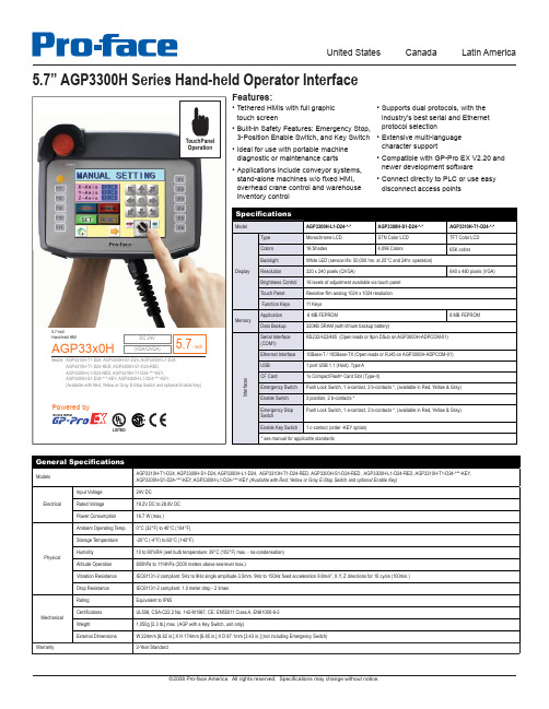
Hand Held, 5.7” TFT Color LCD (VGA), 24VDC, Red E-Stop, No Key
• Extensive multi-language character support
• Compatible with GP-Pro EX V2.20 and newer development software
• Connect directly to PLC or use easy disconnect access points
United States
Canada
Latin America
5.7” AGP3300H Series Hand-held Operator Interface
TouchPanel Operation
Features:
• Tethered HMIs with full graphic touch screen
• Applications include conveyor systems, stand-alone machines w/o fixed HMI, overhead crane control and warehouse inventory control
• Supports dual protocols, with the industry’s best serial and Ethernet protocol selection
Brightness Control 16 levels of adjustment available via touch panel
CDD3000双硬盘 DOCK 用户手册说明书
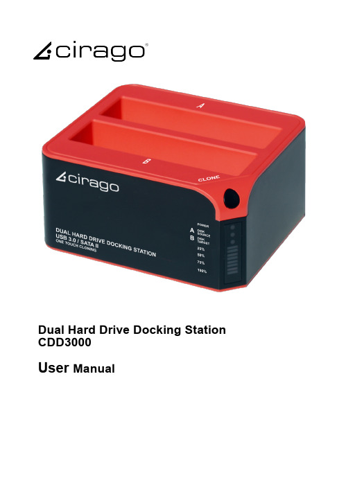
Dual Hard Drive Docking Station CDD3000User ManualIntroductionCDD3000 is a USB 3.0 dual-SATA 2.0 hard drive docking station. It supports simultaneous use of two 2.5” or 3.5” SATA hard disks for both data read and data write. It is also backward compatible with USB 2.0 and USB 1.1. It features One Touch Cloning, which clones your hard drive with touch of a button. One Touch Cloning copies data and system files from Source HDD to Target HDD, so if your Source HDD is bootable, so will your Target HDD.1) Power indicator 2) Slot ‘A’ indicator 3) Slot ‘B’ indicator 4) Clone processing indicator 5) Clone button 6) Slot ‘B’ 7) Slot ‘A’ 8) USB 3.0 input 9) Power switch (ON/OFF) 10) DC inputNote:When using E-SATA interface, the PC can only recognize one HDD in the docking station. If two HDDs are in the docking station, only Slot ‘A’ HDD will be recognized by the PC. If only one HDD is inserted to the dock, then you may use either Slot ’A’ or Slot ’B’.Function:•Complies with Gen2i/Gen2m of Serial ATA II Electrical Specification 2.6•Supports SATA II Asynchronous Signal Recovery (Hot Plug) feature•Supports SATA to SATA pass through•Complies with USB 3.0 Specification, USB Mass Storage Class, Bulk-Only Transport Specification•Supports USB Super-Speed/High-Speed/Full-Speed Operation •Supports USB HID operation•Supports USB2.0/USB3.0/eSATA power saving mode •Supports Dual LUN for USB2.0/USB3.0•One Touch Cloning•Easy to Install and Set-up•Design for Windows 2000/XP/Vista/7, Mac OS X or later version.CLONE:Please note the below conditions before clone:-Slot ‘A’ = SOURCE HDD-Slot ‘B’ = TARGET HDD-TARGET HDD’s capacity MUST be larger than SOURCE HDD, otherwise the CLONE cannot be completed. (Same capacity is also not acceptable)-Before CLONE function starts, make sure you back up any important data in TARGET HDD; once CLONE started, all data from TARGET HDD will gone.-Once the docking station is connected to the PC via USB, One Touch Cloning will not be active. See Cloning with USB section for details.1)One Touch Cloninga) Insert source HDD to Slot ‘A’; target HDD to Slot ‘B’, and then turn on the powerb)Once the Slot indicators are on, that means CDD3000 is ready for cloning.c) Press and hold the clone button for 3 seconds until the indicator light is on, press the button once more for Clone confirmation. Cloning process begins.d) Clone progress indicator flashes and shows the progress (25%, 50%, 75%, 100%).e) Once cloning is finished, all progress indicators will light up.f) Turn off power and remove the HDDs carefully2) Cloning with USBSoftware Installation (Windows only)a) Please insert the CD drive and click “setup.exe”. Chooseb) Fill in the S/N # accordingly (you can find the S/N# on the cover of CD)c) Click “Install” to begin installationd) Installation progress is displayedClone from Source HDD to Target HDDa) Insert Source HDD and Target HDD into the docking station and connect CDD3000 to PC via USB cable. Turn on the power, and you can find the clone icon on the right bottom of window. Double click the CLONE Icon to start the program.CLONE Iconb) CloneDrive activated, click “Start”c) Press start to proceed with Cloned) Clone progress is displayede) Click “OK” once clone is finishedf) You should find the same contents of Source HDD in Target HDDg) If your target HDD has extra space, the system will allocate it to “unallocated” area automatically, please refer to the below picture. Windows system only allows a maximum of fourprimary partitions, if the original disc already exist fourprimarypartitions, then it can not distinguish the extra space but logical drives can have more than oneHDD Partitiona) Open Disk management and select the unallocated areab) Right click “New partition” for further actionc) “Next”d) Base on your need and click “Next”e) Please enter the new partition capacity and click “Next” for further actionf) Assign the drive letter and “Next”g) Select “Quick Format” to format the new partitionh) Click “Finish”i) m Partition completed, the new partition can be found.Limited WarrantyThis is to certify that this Product is free of congenital defects in materials and workmanship. Cirago’s Limited warranty provides the customer 1-year free service with the following conditions:1. Warranty service is valid only in the United States and only applies to Cirago Products.2. If you are having trouble with a product, before seeking limited warranty service, first following the troubleshooting procedures that Cirago or your reseller provides.Visit to download product drivers and troubleshooting instructions.3. If you are unable to correct the problem after following the troubleshooting instructions, please call the Cirago service hotline at 408-331-8824. Have your product’s serial number and your date of purchase available when you make the call to expedite service.4. If the problem cannot be corrected over the telephone, you must take the Product, or deliver the Product freight prepaid, in either its original packaging or packaging affording an equal degree of protection to Cirago’s service center together with a copy of your dated proof of purchase, a complete explanation of the problem and a return address. Do not include other items with the defective Product.5. Any Product received by Cirago's service center that is not covered by the limited warranty will be returned unrepaired.6. We are responsible for repairing or replacing parts that are considered manufacturing defects or damaged under normal user behavior by our technicians. These parts will be free of charge within the 1-year warranty period from the date of purchase.7. All damaged parts will become Cirago’s property.8. Free warranty service will not be provided if:i) The Product has been explicitly or implicitly modified, tampered with, altered or repaired in any way by persons other than our technicians or approved vendors; orii) The Product has been damaged due to misuse, negligence, accident, shipment, inserts or natural calamities; or iii) The Product has been installed, maintained or operated not in accordance with the instructions furnished by Cirago; or iv) Any damage, deterioration or malfunction is caused by power interruption or abnormal voltage input.9. Warranty will only be valid if the date of purchase on the warranty card corresponds with that of the official purchase receipt.10. The warranty card should be properly completed and mailed back to the address indicated within 14 Days of purchase.11. The original purchase receipt shall be provided upon request for service.12. Under no circumstances will Cirago be liable for any consequential damages caused in relation to the use of this product.13. This warranty gives you specific legal rights, and you may have other rights which vary from state to state.For your convenience, Cirago has established a service hotline for frequently asked questions and service assistance or resolution of a service problem, or for product information or operation:Cirago Service CenterAddress: 611 Vaqueros Ave., Sunnyvale, CA 94085Service : 408-331-8824。
USB线检验规范(含表格)
USB线检验规范(IATF16949-2016/ISO9001-2015)1.0目的:1.1确保公司生产的USB线均能正确检验,以确认其符合品质要求。
2.0范围:2.1公司生产所需的USB线,包括来料、制程、成品等。
3.0职责:3.1品保部:负责对USB的来料、制程、成品的抽检检验;3.2SQE负责NG处理。
4.0名词定义:无5.0步骤:5.1. 确认以下资料是否完整:●供应商在合格供应商清单上●有零件承认书和工程资料备注:如上任何一条不完整,不可进行检验。
5.2 抽样方案:具体参照《检验抽样管理规范》中二级检验水准单次抽样计划执行正常检验,采用AQL:MAJ0.25进行抽样。
5.3 检验内容与记录:5.3.1 外观与尺寸检验:序号项目内容检验方法备注1 包装完整、无破损、包装正确、厂商、日期、ROHS等标示正确目视检验2 外观外观完好、无刮伤、变形、沾污、氧化、表面光亮、有光泽、不粗糙目视检验对比样品MAJAQL=0.253 尺寸参照根据具体WI或工程图纸游标卡尺MAJ AQL=0.255.3.2 可靠性检验:序号项目试验方法和条件要求1 额定电压/电流电阻负载AC30/1AmaxF=50/60Hz2 接触电阻电压≤20mV电流I≤100mA USBAM≤30mΩMICRO5PIN≤50 mΩ3 绝缘电阻直流电压DC=300V ≥20MΩ4 耐电压交流电压AC=500V频率F=50/60Hz时间T=1min漏电流I≤1mA不可有短路,绝缘破坏5 插入力速度U=12.5mm/min ≤35N6 拔出力速度U=12.5mm/min USBAM≥10NMICRO 5P≥8N7 反复操作无负荷的情况下,以6-7次/min的速度反复插拔USBA公3000次/MICRO5P10000次插入力≤35N拔出力≥8N接触电阻≤50 mΩ绝缘电阻≥20MΩ耐电压不可短路,绝缘破坏8 弯曲强度固定插头一端,在电线的任意位置加上500g的重量,以每分钟20次的速度,左右往返60o ,120o为一次做3000次弯曲不可有芯线断线,短路等9 抗拉强度在插头与电线间加上荷重5Kg,静吊1min 不可有芯线断线,短路等10 耐热性在温度85℃±2℃中放置48h后取出,在常温常湿的环境下放置1h-2h后进行测试接触电阻≤100 mΩ绝缘电阻≥20MΩ耐电压:不可有短路,绝缘破坏外观:不可有明显的生锈,变色,破裂等11 耐寒性在温度-40℃±3℃中放置48h后取出,在常温常湿的环境下放置1h-2h后进行测试12 耐湿性在温度70℃±2℃相对湿度90%-95%中放置48h后取出,在常温常湿的环境下放置1h-2h后进行测试13 盐雾温度35℃±2℃,盐水浓度(重量比:5%±1%)连续喷雾24h后,在常温常湿的环境中放置1h-2h后进行测试接触电阻≤100 mΩ14 冷热循环以下面列表所示的温度,连续循环5次后,在常温常湿的环境中放置1h-2h后进行测试接触电阻≤100 mΩ阶段温度放置时间1 -40℃±3℃2h2 常温1h3 85℃±3℃3h4 常温1h6.0相关文件:6.1 物料承认书6.2 公司各产品工程图面6.3进料检验管理程序6.4 成品检验程序6.5 检验抽样管理规范6.6 不合格品控制程序7.0使用表单:7.1 IQC检验报告IQC进料检验报告(2).xls7.2 材料不良状况联络单材料不良联络书.xls7.3 供应商品质履历表供货商品质记录履历表.doc7.4 成品检验报告成品检验报告.doc。
USB信号完整性测试讲解

USB信号完整性测试讲解USB 2.0 信号完整性测试需要使用示波器,大部分示波器使用大同小异,本文详细讲解USB2.0的信号完整性测量过程。
测试工具用于高速USB信号质量测试工具包括:1)使用SMA线缆的测试装置,如下图:该设备包括两个RF SMA (m) 垂直50 ohm 终端连接器和两个4 英寸USB A-B 电缆(E2646-61601)、一个USB 2.0 插头和USB 2.0 微型插头之间的转接插头,以及一条从主机端口给该装置供电的电缆。
下图为高速信号质量测试装置有连接SMA 电缆。
2)使用测试探头,如下图探头包括一对差分引线3)测试电缆:4)测试设备(主机)可以从USB Implementers Forum 网站的开发人员工具页下载高速电气测试工具包软件(USBHSET)。
USB设备高速信号质量测试流程操作1.在设备高速信号质量测试装置上,将TEST 开关(S1) 置于ON 位置。
验证黄色TEST LED 亮起。
2.在示波器前面板上,按下[Analyze] 分析键。
3.在"分析菜单"中,按下功能软键,选择USB 信号质量。
4.按下测试软键,选择设备高速信号质量测试。
5.按设置软键。
在"USB 信号质量"菜单中:a)按下测试连接软键,选择是使用单端(带SMA 电缆)还是差分探头连接。
b 如果使用差分连接,请按下源软键,选择连接到差分探头的模拟输入源通道。
b)如果使用单端(SMA 电缆)连接,请按下DP SMA 软键,选择连接到D+信号的模拟输入源通道。
然后,按下DN SMA 软键,选择连接到D- 信号的模拟输入源通道。
在4 通道示波器上,将强制您对D+ 和D- 信号使用不同的通道对。
这将提供最大采样率。
(通道1 和2 是一对,通道3 和4是另一对。
)通道示波器不支持使用单端SMA 电缆连接进行高速测试,因为采样率不符合所需的5 GSa/s。
c)按下测试类型软键,选择近端或远端。
element H USB 3.0 INTERFACE 说明书
USB 3.0 Interface User ManualIn order to improve the quality of the PC USB port through the data transmission and the noise level of power supply, element H USB 3.0 INTERFACE is made to meet the high standard requirements of Hi-Fi audio transmission and from source signal to bring a complete change.Using the USB 3.0 bridge chip from Texas Instruments and a Crystek CCHD-575 super-low noise femtosecond clock, which opens up an independent data channel for USB audio stream, by the means of bypassing from the USB controller on the motherboard, directly bridging to PCI-E port, and to avoid sharing the data channel with other USB devices.The multiple filter units are integrated for USB power supply, which uses the heavy current LDO chip with 6μVRMS and the solid-state capacitor, even if it's using the internal power supply, it can also filter the high-frequency noise of PC switching power. The USB port can supply a maximum currentat 5V 1500mA for all audio devices supplied by the USB port, as well as the measuring function to over-current and short circuit.The two power supply (external/internal) modes can be configured through the switch on the dam-board. With regard to the non-USB power supply audio devices, you can switch off the power supply of the USB port.The four-layer PCB with high speed circuit design standard, according with the differential on the impedance standards and line length requirements. The CNC aluminum enclosure covers the entire board, effectively shielded radiation interference from computer chassis, meanwhile taking intoaccount the cooling requirements of power supply chip.Summary 1. SummaryBracket2. BracketExternal power supply port 123USB3.0 port (compatible with USB2.0/1.1/1.0)Switch for power supply modeSide3. Side212SATA-15Pin power supply port (for internal power supply)PCI-E x1 Gen2 port1Installation 4. InstallationInstallation for boardTo prevent the hardware damage, please unplug the computer power cable before installing the card. To prevent static damage to the card, please release of static electricity before touch the card. According to the specification of your own PC, you should use the attached dam-board with two M3*6mm screws to fix it on the board enclosure.Then choose the PCI-E x1 port on the main-board or PCI-E x4/x8/x16 port to install the board, while fastening the screws and connecting SATA-15Pin power cable from PC power supply to the socket at the rear-end of the board. (Not necessary for external power supply.) As shown below:123Driver installation 5. Driver installationYou can see the device name when your PC find the new hardware under the Windows7/8/8.1/10 system, as shown below:The driver can be downloaded automatically under Windows8/8.1/10 system.If not, please visit to download the driver.The driver not necessary for mainstream Linux OS.6. USB power supply settings:By sliding the switch on the rear panel of card can set the USB port power supply mode, this switch is a three-position switch, as shown below:OFF: Turn off the USB port output power, when the external DAC and other products do not need USB bus power supply. In this mode, the devices such as USB flash disk which require USB bus power supply will not be available.INT: Internal power supply, USB bus power supply from SATA_15P port on the end of card, the input power through the low noise LDO regulator and output from the USB port.EXT: External power supply, USB bus power supply from the DC input port which on the rear panel of the card, the power from DC input through the low noise LDO regulator and then output from USB port.Precautions:Some USB devices do not use the power supply from USB port, but it does not mean the bus power supply could be unplugged, or it will cause the USB devices to malfunction.Please disconnect your USB device before you change the power supply mode of element H. If you switch the power supply mode when device is connected, the USB bus power supply surge may cause the device to malfunction.When the USB port does not work properly, please check the following items:Make sure that the card is properly installed in the PC chassis and that the driver is installed correctly, the hardware device is visible in the Device Manager after the driver is properly installed. Use the internal power supply, please ensure that the SATA_15Pin connector on the end of the card is properly connected to the power cable in the PC chassis.Use an external power supply, please ensure that the DC input jack on the rear panel of card is proper-ly connected to the external power supply and within the appropriate voltage range. Make sure that the power supply mode switch on the rear panel of the card is in the correct position, set to "INT" when using internal power supply, set to 'EXT' when using external power supply, and 'OFF' when no need power supply.Technical specifications 7. Technical specificationsUSB PortUSB 3.0-Compliant x HCI Host ControllerPCI-E x1 Gen2 InterfaceOne downstream portSpecifications for power supplyUSB power supply:5V/1500mA MAXExternal power supply:DC 9~12V,≥1200mAPower supply port: outer diameter 5.5mm inner diameter 2.1mm (+ for inner, - for outer) Notice: Don't connect to the power above 12V, or will damage the device! Boundary dimension114 x 64 x 23 mm (including protruding parts)For purpose of improvement design and specifications are subject to change without notice.Customer service098. Customer serviceFrom purchase date, we provide you one-year-limited warranty, warranty does not contain the accessories.Free warranty is only for the faulty caused by the quality, not including the wrong operation, negligence or accident.It is beyond our free warranty terms when you change the components or fix it by your own.For more information, please visit .201811 Ver.1.0。
USB3.0规范标准与技术内容解析
USB3.0 规范标准与技术内容解析
随着电子产品的小型化集成化发展,USB 接口的标准也迎来了必须变化 的时刻。原有的 USB2.0 标准已经无法满足新产品的科技需要,于是新的 USB3.0 技术走进人们的生活。但是很多人对于 USB3.0 技术仍旧不是非常了 解,针对于此,本文就将针对 USB3.0 的规范内容进行介绍,并对其技术内 容进行解析。 传输速率 新标准超高速接口的实际传输速率大约是 3.2Gbps(即 400MB/S)。理论上 的最高速率是 5.0Gbps(即 625MB/S)。 数据传输 USB3.0 引入全双工数据传输。5 根线路中 2 根用来发送数据,另 2 根用来 接收数据,还有 1 根是地线。也就是说,USB3.0 可以同步全速地进行读写操 作。以前的 USB 版本并不支持全双工数据传输。 电源 电源的负载已增加到 150 毫安(USB2.0 是 100 毫安左右),配置设备可以 提高到 900 毫安。这比 USB2.0 高了 80%,充电速度更快。另外,USB3.0 的 最小工作电压从 4.4 伏特降到 4 伏特,更加省电。 电源管理 USB3.0 并没有采用设备轮询,而是采用中断驱动协议。因此,在有中断请 求数据传输之前,待机设备并不耗电。简而言之,USB3.0 支持待机、休眠和 暂停等状态。 物理外观 上述的规范也会体现在 USB3.0 的物理外观上。但 USB3.0 的线缆会更
Hale Waihona Puke “厚”,这是因为 USB3.0 的数据线比 2.0 的多了 4 根内部线。不过,这个插口 是 USB3.0 的缺陷。它包含了额外的连接设备。 已支持的操作系统 WindowsVista、Windows7(据传要等到 Windows7SP1)和 Linux 已支持 USB3.0.Mac 还在观望,应该也会支持的。鉴于 WindowsXP 的“年纪”,它能 支持 USB3.0 的希望几乎渺茫。
星辰科技 ST4200USBM 可拔枪式4口坚固工业USB串口说明书

DE: Bedienungsanleitung - FR: Guide de l'utilisateur - ES: Guía del usuario - IT: Guida per l'uso - NL: Gebruiksaanwijzing - PT: Guia do usuário - ST4200USBMMountable 4 Port Rugged Industrial USB Hub *actual product may vary from photosFCC Compliance StatementThis equipment has been tested and found to comply with the limits for a Class B digital device, pursuant to part 15 of the FCC Rules. These limits are designed to provide reasonable protection against harmful interference in a residential installation. This equipment generates, uses and can radiate radio frequency energy and, if not installed and used in accordance with the instructions, may cause harmful interference to radio communications. However, there is no guarantee that interference will not occur in a particular installation. If this equipment does cause harmful interference to radio or television reception, which can be determined by turning the equipment off and on, the user is encouraged to try to correct the interference by one or more of the following measures:• Reorient or relocate the receiving antenna.• Increase the separation between the equipment and receiver.• Connect the equipment into an outlet on a circuit different from that to which the receiver is connected.• Consult the dealer or an experienced radio/TV technician for help.Use of Trademarks, Registered Trademarks, and other Protected Names and SymbolsThis manual may make reference to trademarks, registered trademarks, and other protected names and/or symbols of third-party companies not related in any way to . Where they occur these references are for illustrative purposes only and do not represent an endorsement of a product or service by , or an endorsement of the product(s) to which this manual applies by the third-party company in question. Regardless of any direct acknowledgement elsewhere in the body of this document, hereby acknowledges that all trademarks, registered trademarks, service marks, and other protected names and/or symbols contained in this manual and related documents are the property of their respective holders.Table of ContentsIntroduction (1)Features (1)Package Contents (1)Connector Layout (2)Hardware Installation (3)Checking the Hub Installation (4)Specifications (4)Technical Support (5)Warranty Information (5)IntroductionThank you for purchasing a ST4200USBM High-Speed 4-Port USB2.0 hub. This ruggedly built hub is ideal for industrial environments and can be wall-mounted or installed onto a DIN rail for convenient access to the ports. This four port industrial hub can be bus-powered or self powered, with a three wire terminal block connector (7-24V).Features• Choice of Bus Power and/or External Terminal Block Power• Compact space saving and mountable design (mount on a wall or DIN rail)• Max data transfer rate of up to 480 Mbps and backwards compatible with USB 1.1 • Includes a 2 meter USB cable for quick and easy installationsPackage Contents• USB 2.0 Hub• User’s Manual• 2m USB A-B cable• DIN Rail Mounting KitConnector LayoutActivity LEDs for Downstream Ports: These 4 LED indicators will blink whenever the USB ports are transferring data.Upstream Port Connector: Type-B USB connector for upstream USB connection.Self-Power Input Connectors: 3-Pin terminal block connectors used to connect the hub to an available power source. The voltage can be in the range of +7V to 24VDC.WARNING: Ensure that the polarity of the input power is correctly matched to that ofthe terminal block pins. Otherwise, it may damage the hub.Hardware Installation1. Use static electricity discharge precautionsEliminate the potential for static discharge from any objects that the hub may come in contact with before the installation. This can be accomplished by touching a bare metal chassis rail after you have turned off the power.2. Apply DC power to the 3-pin Terminal Block ConnectorThe terminal block connector adds power to ensure there is enough to run the 4 downstream USB ports.3. Connect the USB host cableThe host cable is a standard A-to-B USB2.0 cable. Connect the type-A connector to the upstream USB port being used, then connect the type-B connector to the USB hub. Since the hub is plug and play, it can be connected while the host computer is powered on.4. Connect the USB devices to the downstream ports of the hub.5. Mount the hub on the wall or DIN RAIL if required.Checking the Hub InstallationTo check the USB hub installation in Windows Device Manager, follow these steps:1. Click Start2. Click Control Panel3. Click System4. Click Device Manager5. Double click Universal Serial Bus Controller6. Double click Generic USB HUB7. The message should show that the device is working properlySpecificationsTechnical Support’s lifetime technical support is an integral part of our commitment to provide industry-leading solutions. If you ever need help with your product, visit /support and access our comprehensive selection of online tools, documentation, and downloads.For the latest drivers/software, please visit /downloads Warranty InformationThis product is backed by a two year warranty.In addition, warrants its products against defects in materials and workmanship for the periods noted, following the initial date of purchase. During this period, the products may be returned for repair, or replacement with equivalent products at our discretion. The warranty covers parts and labor costs only. does not warrant its products from defects or damages arising from misuse, abuse, alteration, or normal wear and tear.Limitation of LiabilityIn no event shall the liability of Ltd. and USA LLP (or their officers, directors, employees or agents) for any damages (whether direct or indirect, special, punitive, incidental, consequential, or otherwise), loss of profits, loss of business, or any pecuniary loss, arising out of or related to the use of the product exceed the actual price paid for the product. Some states do not allow the exclusion or limitation of incidental or consequential damages. If such laws apply, the limitations or exclusions contained in this statement may not apply to you.Hard-to-find made easy. At , that isn’t a slogan. It’s a promise. is your one-stop source for every connectivity part you need. From the latest technology to legacy products — and all the parts that bridge the old and new — we can help you find the parts that connect your solutions.We make it easy to locate the parts, and we quickly deliver them wherever they need to go. Just talk to one of our tech advisors or visit our website. You’ll be connected to the products you need in no time.Visit for complete information on all products and to access exclusive resources and time-saving tools. is an ISO 9001 Registered manufacturer of connectivity and technology parts. was founded in 1985 and has operations in the United States,。
长城汽车使用手册说明书
操作
介绍了钥匙、车门、车窗、座椅等车内装备的基本操作方法。
驾驶
介绍了车辆启动、换挡方法、仪表等驾驶相关内容。
视听系统
介绍了蓝牙电话、系统设置等视听系统相关内容。
安全性
介绍了车辆防盗系统、安全带等保护装置。
紧急情况
介绍了爆胎、蓄电池亏电等车辆故障的处理方法。
维护保养
介绍了车辆的日常检查以及定期维护保养的事项。
4
外观 A
B
C
DE
F
G
H
I
J
K
5
Ⓐ 货箱门把手 25 Ⓑ 高位制动灯 Ⓒ 车窗 28 Ⓓ 外后视镜 47 Ⓔ 前雨刮 54 Ⓕ 门锁 22
Ⓖ 倒车影像 93 Ⓗ 后组合灯 49 Ⓘ 充电口 33 Ⓙ 前组合灯 49 Ⓚ 侧转向灯 49
6
内饰
AB
C
D EF G
H
IJK
L MN
QO
7
Ⓐ 中控锁按钮 22 Ⓑ 灯光控制组合开关 49 Ⓒ 组合仪表 120 Ⓓ 雨刮控制组合开关 54 Ⓔ 中控面板开关总成 Ⓕ 换挡杆 87 Ⓖ 空调出风口 61 Ⓗ 车门内扣手 23
〉 谨慎驾驶:务必谨慎驾驶。随时注意路面 上其他驾驶员或行人的错误动向,以便及 时做出判断,防止意外事故的发生。
〉 专注驾驶:驾驶时务必全神贯注。任何分 散驾驶员注意力的事情,如调节控制按 钮、接打手机或阅读都可能引发碰撞事故 并导致您、车上的乘客以及其他人员严重 伤亡。
警告
禁止将儿童单独留在车内,也不要让儿童携 带或使用钥匙。 儿童可能会启动车辆或随意切换换挡杆挡 位。儿童玩耍车窗、天窗或车辆的其他设备 时也可能会伤害到他们自己。此外,车内温 度过高或过低,也可能会对儿童造成致命伤 害。
五大USB30解决方案速度比拼

目前市场上提供USB 3.0接口的主板越来越多,新上市的中高端主板USB 3.0接口基本上成为了标配,甚至还有些低端的H61主板也带了USB 3.0接口,随着原生支持USB 3.0的AMD A75主板上市,USB 3.0又向着全民普及前进了一大步。
除了AMD A75主板外,目前其他在售的主板上的USB 3.0接口都是通过第三方芯片桥接出来的,各个厂家有各自的方案,性能上也会有所不同,基本上都是通过PCI-E 2.0通道与主板芯片组(南桥)连接,不过在P55、H55这些主板上由于主板芯片提供的是PCI-E 1.1的带宽,因此速度上会有所限制。
话说早在AMD A75主板推出时就想测试一下原生的USB 3.0接口与桥接的在性能上有什么差别,不过单纯与一款方案对比的话好像有点不靠谱,毕竟不能用一家的芯片来代表全部第三方芯片的性能,于是索性找来了目前常见的USB 3.0解决方案来一次大比武。
除了A75之外,还包括有NEC、钰创、祥硕和威盛等第三方USB 3.0控制器,一共五种解决方案。
常见的USB 3.0解决方案NEC D720200F1桥接芯片NEC D720200F1芯片,是最早推出的USB 3.0控制芯片,在去年NEC 的芯片基本上独占了这个市场,当时几乎所有拥有USB 3.0接口的主板都搭载了这颗芯片,它可以提供两个USB 3.0接口,支持xHCI 0.96,目前是非常常见的一颗USB 3.0控制芯片。
钰创(EtronTech)EJ168A桥接芯片钰创(EtronTech)的EJ168A USB 3.0控制芯片,与其他几款芯片相比个体比较大,在技嘉和华擎新推出的Intel 6系列主板上较为常见,同样的它可以提供两个USB 3.0接口,是目前市场上可以买到的唯一一款支持xHCI 1.0的芯片。
相比xHCI 0.96,xHCI 1.0能提供更好的驱动和硬件性能,提供更好的向下兼容性,更加复杂,认证更难,这也是很多USB 3.0控制器只能通过xHCI 0.96但不能通过xHCI 1.0认证的原因。
通用充电器快充协议QC2.0,QC3.0,MTK PE,PE+,充电识别

通用USB充电器(快充)说明一、快充的意义:USB得到广泛普及是因为其能够为外围设备供电。
USB孕育于上世纪90年代中期,最初的目的是将外部设备(例如键盘、鼠标、打印机、外置驱动器等)连接至计算机。
随着越来越多的各种便携式设备受到青睐,也同样需要为其供电。
利用数据传输连接器供电的能力使得USB在便携式市场具有直接而显著的优势。
在2007年第一个电池充电规范颁布之前,尝试为电池充电本质上是一种冒险——结果非常难以预测。
2009年4月,全球移动通信系统协会(GSMA)联合OTMP(手机开放组织联盟)17家移动运营商和制造商宣布实施跨行业的通用充电器标准,此标准采纳了USB-IF的micro-USB接口作为手机数据和充电的统一接口,并采纳USB-IF的Battery Charging 规范作为充电规范。
USB-IF公布了BC 1.1版的电池充电规范,到2010年BC1.2版也正式发布。
即使有BC1.2规范可循,有些电子设备制造商仍然为其专用充电器开发定制协议(例如Apple)。
当您将这样的设备连接至完全符合BC1.2规范的充电端口时,可能仍然会产生报错消息:“Charging is not supported with this accessory.”(不支持该附件充电)。
直到目前给智能设备充电(包括手机,平板电脑,蓝牙设备)等,在国际上还没有统一的强制性的标准出台,各个厂家都有着自己的定义,当前以苹果,三星,及其部分国内的安卓机为代表,有着自已的定义的充电规范,存在互不兼容的情况。
而伴随着大电池容量的智能设备增加,有些设备的电容容量大于了3000mA/H,平板电脑有些达到10000mA/H以上。
采用Type-A及MicroA/B接口的手机受限于USB2.0标准的影响,充电电流限制在1.5A以下,接口允许的最大电流为1.8A。
各手机厂家自定义数据线可以将电流提升到2A,但当电流大于2A后损耗将变得很大。
USBCAN-I-mini 小型智能 CAN 接口卡产品用户手册说明书
USBCAN-I-mini小型智能CAN 接口卡修订历史目录1. 功能简介 (1)1.1产品概述 (1)1.2参数指标 (1)1.3产品外观 (2)1.4典型应用 (2)2. 设备安装 (3)2.1CAN-bus 连接器 (3)2.2信号指示灯 (3)2.3系统连接 (4)2.3.1CAN 总线连接 (4)2.3.2总线终端电阻 (5)3. 驱动程序安装 (6)3.1在Windows系统下第一次安装驱动程序 (6)3.2检查设备是否安装成功 (7)3.2.1打开WINDOWS设备管理器 (7)3.2.2确认新的设备是否已经成功安装 (8)3.3在Linux下驱动安装 (8)4. 快速使用指南 (9)CANTest基本操作 (9)4.1.1设备类型选择 (9)4.1.2滤波设置 (10)4.1.3启动CAN (11)4.1.4获取设备信息 (12)4.2发送接收实验 (13)4.2.1搭建测试环境 (13)4.2.2打开设备 (13)4.2.3发送数据 (13)4.2.4实时保存与停止保存 (15)4.2.5总线利用率 (15)4.2.6错误信息显示 (16)5. 接口库函数使用方法 (17)5.1在windows下调用动态库的方法 (17)5.1.1VC调用动态库的方法 (17)5.1.2VB调用动态库的方法 (17)5.2接口库函数使用流程 (19)6. 检查和维护 (20)7. 免责声明 (22)附录A CAN报文滤波器设置 (23)A.1单滤波配置 (23)A.2双滤波配置 (25)附录B DB9转OBD接口 (28)B.1功能简介 (28)B.2技术参数 (28)B.3引脚信息 (28)B.3.1DB9接头引脚排列 (28)B.3.2DB9接头引脚描述 (29)B.3.3OBD接头引脚排列 (29)B.3.4OBD接头引脚描述 (30)B.4机械尺寸 (30)附录C SJA1000标准波特率 (31)1. 功能简介1.1 产品概述USBCAN-I-mini智能CAN接口卡是系列USBCAN便携版本,与USBCAN-I单路智能CAN接口卡完全兼容。
- 1、下载文档前请自行甄别文档内容的完整性,平台不提供额外的编辑、内容补充、找答案等附加服务。
- 2、"仅部分预览"的文档,不可在线预览部分如存在完整性等问题,可反馈申请退款(可完整预览的文档不适用该条件!)。
- 3、如文档侵犯您的权益,请联系客服反馈,我们会尽快为您处理(人工客服工作时间:9:00-18:30)。
USB3000数据采集卡硬件使用说明书北京阿尔泰科技发展有限公司产品研发部修订北京阿尔泰科技发展有限公司目录目录 (1)第一章功能概述 (1)第一节、产品应用 (1)第二节、AD模拟量输入功能 (1)第三节、DI数字量输入功能 (2)第四节、DO数字量输出功能 (2)第五节、其他指标 (2)第六节、产品安装核对表 (2)第七节、安装指导 (2)一、软件安装指导 (2)二、硬件安装指导 (2)三、外接电源 (2)第八节、板卡尺寸 (2)第二章元件布局图 (4)第一节、主要元件布局图 (4)第二节、主要元件功能说明 (4)一、信号输入输出连接器 (4)二、物理ID拨码开关 (4)三、跳线器 (5)四、状态指示灯 (5)第三章信号输入输出连接器 (6)第一节、AD/DA模拟量信号输入输出连接器定义 (6)第二节、DI/DO数字量信号输入输出连接器定义 (7)第四章各种信号的连接方法 (8)第一节、AD模拟量输入的信号连接方法 (8)一、AD单端输入连接方式 (8)二、AD双端输入连接方式 (8)第二节、DI数字量输入的信号连接方法 (9)第三节、DO数字量输出的信号连接方法 (9)第四节、时钟输入输出和触发信号的连接方法 (9)第五节、多卡同步的实现方法 (10)第五章数据格式、排放顺序及换算关系 (12)第一节、AD模拟量输入数据格式及码值换算 (12)一、AD双极性模拟量输入的数据格式 (12)二、AD单极性模拟量输入数据格式 (12)第二节、AD单通道与多通道采集时的数据排放顺序 (12)第六章各种功能的使用方法 (14)第一节、AD触发功能的使用方法 (14)一、AD内触发功能 (14)二、AD外触发功能 (14)第二节、AD连续与分组采集功能的使用方法 (15)一、AD连续采集功能 (15)二、AD分组采集功能 (16)USB3000数据采集卡硬件使用说明书版本:6.005第三节、AD软件自动校准 (19)第八章产品的应用注意事项、校准、保修 (20)第一节、注意事项 (20)第二节、保修 (20)北京阿尔泰科技发展有限公司第一章功能概述信息社会的发展,在很大程度上取决于信息与信号处理技术的先进性。
数字信号处理技术的出现改变了信息与信号处理技术的整个面貌,而数据采集作为数字信号处理的必不可少的前期工作在整个数字系统中起到关键性、乃至决定性的作用,其应用已经深入到信号处理的各个领域中。
实时信号处理、数字图像处理等领域对高速度、高精度数据采集卡的需求越来越大。
ISA总线由于其传输速度的限制而逐渐被淘汰。
我公司推出的基于PCI总线、USB总线等数据采集卡综合了国内外众多同类产品的优点,以其使用的便捷、稳定的性能、极高的性价比,获得多家客户的一致好评,是一系列真正具有可比性的产品,也是您理想的选择。
第一节、产品应用USB3000卡是一种基于USB总线的数据采集卡,可直接和计算机的USB接口相连,构成实验室、产品质量检测中心等各种领域的数据采集、波形分析和处理系统。
也可构成工业生产过程监控系统。
它的主要应用场合为:■ 电子产品质量检测■ 信号采集■ 过程控制■ 伺服控制第二节、AD模拟量输入功能◆ 转换器类型:AD7612BSTZ◆ 输入量程:±10V、±5V(默认)、0~10V、0~5V◆ 转换精度:16位(Bit)◆ 采样速率(Frequency):31Hz~500KHz注释:各通道实际采样速率 =总采样速率/采样通道数分频公式:采样频率 =主频 / 分频数,其中主频 =40MHz,32位分频,分频数的取值范围:最低为80,最高为1290322◆ 物理通道数:32通道(单端SE),16通道(双端DI)◆ 采样通道数:软件可选择,通过设置首末通道实现(LastChannel – FirstChannel + 1)◆ 通道切换方式:首末通道顺序切换(软件触发切换,只有发出读数据命令时才有切换动作)◆ 模拟量输入方式:单端模拟输入和双端模拟输入(双端也叫差分输入)◆ 数据读取方式:非空和半满查询方式◆ 存诸器深度:16K字(点)FIFO存储器◆ 存储器标志:非空、半满◆ 采集方式(ADMode):连续(异步)与分组(伪同步)采集◆ 组间间隔(GroupInterval):软件可设置,最小为采样周期(1/Frequency),最大为32767uS (时间)◆ 组循环次数(LoopsOfGroup):软件可设置,最小为1次,最大为255次◆ 触发模式(TriggerMode):软件触发(内触发)和硬件后触发(外触发)◆ 触发类型(TriggerType):边沿触发和脉冲触发(电平)◆ 触发方向(TriggerDir):负向、正向、正负向触发◆ 触发源:DTR(数字触发信号)◆ 触发源DTR输入范围:标准TTL电平◆ 触发灵敏度(TrigWindow):1~255,单位为0.5μS◆ 软件自动校准◆ 程控放大器类型:默认为AD8251,兼容AD8250、AD8253◆ 程控增益:1、2、4、8倍(AD8251)或1、2、5、10倍(AD8250)或1、10、100、1000倍(AD8253)◆ 模拟输入阻抗:10MΩUSB3000数据采集卡硬件使用说明书版本:6.005◆ AD芯片转换时间:1.45uS◆ 非线性误差:±1.5LSB◆ 系统测量精度:0.01%◆ 工作温度范围:0℃~ +50℃◆ 存储温度范围:- 20℃~ +70℃第三节、DI数字量输入功能◆ 通道数:16路◆ 电气标准:TTL兼容◆ 高电平的最低电压:2V◆ 低电平的最高电压:0.8V第四节、DO数字量输出功能◆ 通道数:16路◆ 电气标准:TTL兼容◆ 高电平的最低电压:2.4V◆ 低电平的最高电压:0.5V◆ 上电输出:低电平第五节、其他指标◆ 板载时钟振荡器:40MHz◆ 外接电源:5V 1.5A第六节、产品安装核对表打开USB3000板卡包装后,你将会发现如下物品:1、USB3000板卡一个2、ART软件光盘一张,该光盘包括如下内容:a)本公司所有产品驱动程序,用户可在USB目录下找到USB3000驱动程序;b)用户手册(pdf格式电子文档);第七节、安装指导一、软件安装指导在不同操作系统下安装USB3000板卡的方法一致,在本公司提供的光盘中含有安装程序Setup.exe,用户双击此安装程序按界面提示即可完成安装。
二、硬件安装指导在硬件安装前首先关闭系统电源,待板卡固定后开机,开机后系统会自动弹出硬件安装向导,用户可选择系统自动安装或手动安装。
三、外接电源使用本卡时最好通过板卡上CON1插座接上+5V外接电源。
如本卡不能正常工作,必须接上外接电源。
使用外接电源时,应先接外接电源,后接USB电缆。
拔掉时先拔USB电缆,后拔外接电源。
第八节、板卡尺寸板卡尺寸:120.02mm(长) x 98.81mm(宽)北京阿尔泰科技发展有限公司USB3000数据采集卡硬件使用说明书版本:6.005第二章元件布局图第一节、主要元件布局图第二节、主要元件功能说明请参考第一节中的布局图,了解下面各主要元件的大体功能。
一、信号输入输出连接器CN1:模拟量信号输入输出连接器P1:DIO数字量信号输入输出连接器CON1:外接电源端子,要求外接+5V电源,电流不超过1.5A注解:以上连接器的详细说明请参考《信号输入输出连接器》章节。
二、物理ID拨码开关DID1:设置物理ID号,当PC机中安装的多块USB3000时,可以用此拨码开关设置每一块板卡的物理ID号,这样使得用户很方便的在硬件配置和软件编程过程中区分和访问每块板卡。
下面四位均以二进制表示,拨码开关拨向“ON”,表示“1”,拨向另一侧表示“0”。
如下列图中所示:位置“ID3”为高位,“ID0”为低位,图中黑色的位置表示开关的位置。
(出厂的测试软件通常使用逻辑ID号管理设备,此时物理ID拨码开关无效。
若您想在同一个系统中同时使用多个相同设备时,请尽可能使用物理ID。
关于逻辑ID与物理ID的区别请参考软件说明书《USB3000S》的《设备对象管理函数原型说明》章节中“CreateDevice”和“CreateDeviceEx”函数说明部分)。
北京阿尔泰科技发展有限公司ID0ID1ID2ID3DID1上图表示“1111”,则表示的物理ID 号为15ID0ID1ID2ID3DID1上图表示“0111”,则代表的物理ID 号为7ID0ID1ID2ID3DID1上图表示“0101”,则代表的物理ID 号为5下面以表格形式说明物理ID 号的设置: ID3 ID2 ID1 ID0 物理ID (Hex )物理ID (Dec )OFF (0) OFF (0) OFF (0) OFF (0)0 0OFF (0) OFF (0) OFF (0) ON (1) 11OFF (0) OFF (0) ON (1) OFF (0)2 2OFF (0) OFF (0) ON (1) ON (1) 3 3OFF (0)ON (1)OFF (0) OFF (0) 4 4OFF (0) ON (1)OFF (0) ON (1) 5 5OFF (0) ON (1) ON (1) OFF (0) 6 6 OFF (0) ON (1) ON (1)ON (1) 7 7 ON (1) OFF (0) OFF (0) OFF (0)8 8 ON (1) OFF (0) OFF (0) ON (1) 9 9 ON (1) OFF (0) ON (1) OFF (0) A 10 ON (1) OFF (0) ON (1)ON (1) B 11 ON (1) ON (1) OFF (0) OFF (0) C 12 ON (1) ON (1) OFF (0) ON (1) D 13 ON (1) ON (1) ON (1) OFF (0) E 14ON (1) ON (1) ON (1)ON (1) F15三、跳线器JP6:加载USB 控制器程序,默认情况下1-2脚跨接四、状态指示灯EF :FIFO 非空指示灯,指示灯为亮状态表示FIFO 非空FF :FIFO 溢出指示灯,指示灯为亮状态表示FIFO 溢出 HF :FIFO 半满指示灯,指示灯为亮状态表示FIFO 半满LED3.3V :3.3V 电源指示灯,灯亮时表示+3.3V 供电正常, 灯灭时表示+3.3V 供电不正常。
当正确连接到计算机此灯应亮。
USB3000数据采集卡硬件使用说明书 版本:6.005第三章 信号输入输出连接器第一节、AD/DA 模拟量信号输入输出连接器定义关于50芯SCSI 型插座CN1的管脚定义(图形方式)关于50芯SCSI 型插座CN1的管脚定义(表格形式) 管脚信号名称 管脚特性 管脚功能定义注释 AI0~AI31 Input AD 模拟量输入管脚,分别对应于32个模拟单端通道,当为双端时,其AI0~AI15分别与AI16~AI31构成信号输入的正负两端,即AI0~AI15接正端,AI16~AI31接负端AGND GND 模拟信号地,当输入输出模拟信号时最好用它作为参考地 DGND GND 数字信号地,当输入输出数字信号时最好用它作为参考地NC NC NC NC CLKIN Input 板外时钟输入 CLKOUT Output 板内时钟输出 DTR Input 数字触发信号输入注明:(一)、关于AI0~AI31信号的输入连接方法请参考《AD 模拟量输入的信号连接方法》章节;北京阿尔泰科技发展有限公司(二)、关于CLKIN、CLKOUT和DTR的信号输入连接方法请参考《时钟输入输出和触发信号连接方法》章节,DTR的触发功能的使用方法请参考《AD外触发功能》章节。
