AL422B
RS422数字隔离器IL422

mA
mA
85
°C
kV/μs
DC Stable
Test Conditions
VDD1 = 3.3 V VDD1 = 5.0 V
Insulation Specifications
Parameters Creepage Distance Barrier Impedance Leakage Current
Safetyy or common mode)
VIC
High-Level Digital Input Voltage
VIH
Low-Level Digital Input Voltage
VIL
Differential Input Voltage(2)
VID
High-Level Output Current (Driver)
IL422
Driver Section
Electrical specifications are Tmin to Tmax and VDD = 4.5 V to 5.5 V unless otherwise stated.
Parameters
Symbol
Min.
Typ.(5)
Input Clamp Voltage
Units °C °C V V V V
mW
mA °C kV
Test Conditions
25°C 85°C 10 sec. HBM
Recommended Operating Conditions
Parameters
Symbol
Supply Voltage
VDD1 VDD2
Input Voltage at any Bus Terminal
OV7670使用说明和程序讲解-参考战舰板

图 40.1.1 OV7670 功能框图 OV7670 传感器包括如下一些功能模块。 1.感光整列(Image Array) OV7670 总共有 656*488 个像素,其中 640*480 个有效(即有效像素为 30W) 。 2.时序发生器(Video Timing Generator) 时序发生器具有的功能包括:整列控制和帧率发生(7 种不同格式输出) 、内部信号发 生器和分布、 帧率时序、 自动曝光控制、 输出外部时序 (VSYNC、 HREF/HSYNC 和 PCLK) 。 3.模拟信号处理(Analog Processing)
表 40.1.1 OV7670 模块信号及其作用描述 下面我们来看看如何使用 ALIENTEK OV7670 摄像头模块(以 QVGA 模式,RGB565 格式为例) 。对于该模块,我们只关心两点:1,如何存储图像数据;2,如何读取图像数据。 首先,我们来看如何存储图像数据。 ALIENTEK OV7670 摄像头模块存储图像数据的过程为: 等待 OV7670 同步信号FIFO 写指针复位FIFO 写使能等待第二个 OV7670 同步信号FIFO 写禁止。通过以上 5 个步 骤,我们就完成了 1 帧图像数据的存储。 接下来,我们来看看如何读取图像数据。 在存储完一帧图像以后,我们就可以开始读取图像数据了。读取过程为:FIFO 读指针 复位给 FIFO 读时钟(FIFO_RCLK)读取第一个像素高字节给 FIFO 读时钟读取第 一个像素低字节给 FIFO 读时钟读取第二个像素高字节循环读取剩余像素结束。 可以看出,ALIENTEK OV7670 摄像头模块数据的读取也是十分简单,比如 QVGA 模 式,RGB565 格式,我们总共循环读取 320*240*2 次,就可以读取 1 帧图像数据,把这些数 据写入 LCD 模块,我们就可以看到摄像头捕捉到的画面了。 OV7670 还可以对输出图像进行各种设置,详见光盘《OV7670 中文数据手册 1.01》和 《OV7670 software application note》这两个文档,对 AL422B 的操作时序,请大家参考 AL422B 的数据手册。 了解了 OV7670 模块的数据存储和读取,我们就可以开始设计代码了,本章,我们用一 个外部中断,来捕捉帧同步信号(VSYNC) ,然后在中断里面启动 OV7670 模块的图像数据 存储,等待下一次 VSHNC 信号到来,我们就关闭数据存储,然后一帧数据就存储完成了, 在主函数里面就可以慢慢的将这一帧数据读出来,放到 LCD 即可显示了,同时开始第二帧 数据的存储,如此循环,实现摄像头功能。 本章,我们将使用摄像头模块的 QVGA 输出(320*240) ,刚好和战舰 STM32 开发板使 用的 LCD 模块分辨率一样, 一帧输出就是一屏数据, 提高速度的同时也不浪费资源。 注意: ALIENTEK OV7670 摄像头模块自带的 FIFO 是没办法缓存一帧的 VGA 图像的,如果使用 VGA 输出,那么你必须在 FIFO 写满之前开始读 FIFO 数据,保证数据不被覆盖。
AL422B中文资料

AL422B3M-Bit Frame BufferApplicationsMultimedia systems Video capture systems Video editing systems Scan rate convertersTV’s picture in picture feature Anti-skip CD playersDescriptionThe AL422B is a First-In-First-Output (FIFO) video frame memory used to buffer audio/video/graphic data for digital processing, timing correction, or format conversion. It is manufactured with state-of-the-art embedded memory technology for applications in TVs, VCRs, scan converters, and digital video systems.Ordering InformationPart number PackagePower supply AL422B28-pin plastic SOP+3.3 voltFeatures• 384K (393,216) x 8 bits FIFO organization • Supports VGA and CCIR resolutions• Independent read/write operations (different I/O data rates acceptable)• High speed independent 8-bit data I/O port operations• Maximum operating speed grade: 50Mhz • Access time: 15 ns• Output enable control (data skipping) • 3.3V power supply with 5V signal input tolerant•Standard 28-pin SOP package DI0DI1DI2DI3/WE GND TST /WRST WCK VDD DI4DI5DI6DI7DO0DO1DO2DO3/RE GND /OE /RRST RCK DEC DO4DO5DO6DO7AL422-04 422B pinout diagramThe AL422B consists of 3Mbits of memory, and is configured as 393,216 words x 8 bit FIFO (first in first out). The built-in address and pointer control circuits provide a straightforward bus interface to serially read/write memory that can reduce inter-chip design efforts. The 8-bit read/write ports can operate independently at a maximum speed of 50Mhz.Current sources of similar memory (field memory) in the market provide limited memory size which is only enough for holding a TV field, but not enough for a whole PC video frame which normally contains 640x480 or 720x480 bytes. The AverLogic AL422 provides 50% more memory to support high resolution for digital PC graphic or video applications. The 50% increase in speed also expands the range of applications.For more information about the AL422B or other AverLogic products, please contact your local authorized distributor, representative, visit our website, or contact us directly.D ISTRIBUTED BY:A VER L OGIC T ECHNOLOGIES,I NC.TEL:1408361-0400 e-mail: sales@ URL: February 28, 2002。
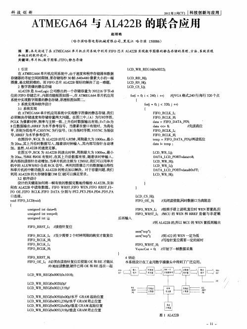
ATMEGA64与AL422B的联合应用
L CD RD
_
HO ;
L CD RS } ; 1 0 L CD C - sI ; 0
—
一
_
f =0 i 4; 抖) ! V A ̄ 0 ; <20 i / G , Q
{
, 0 ; 30 2 , 每行 2 个i ; ( 2, {
d t - tmp ; aa I e
L D WR -; C J O
DATA LCD POR -d t> ; r aa >8
L D WR ; C H0 L D WR 0 C L;
DATA LCD PORT a a t&0x FF;
L D R H0 C W :
FI FO RCL H; K
, / 写指针复位需要一定的延时
V yc n =0 / snC t ; / 开始下 一帧数据采集
4结 论 本系统设 计在工业用 数字摄像头 中得 到 了广泛应用 。
FI FO RCLK
— — — _
在 A ME A 4单片机应用系统中实现数字图像的静态存储, T G 6 我们 必须解决存储速度和存储容量两大问题。在图三中, ( A)为行时序图, PL C K为像素时钟, 频率与主频一致 , 上升沿时数据输 出有效;< : 为 Y 7O > 8 位数据输出; R F H E 为水平参考信号 ,当像素在窗口有效时 ,为高电 平, 否则为低 电平 ;H Y C为行信号。( ) CSN B 为场时序图,S N V Y C为场信 号, R F H E 为水平参考信号。 在 图四 中 , K为 A 4 2 WC L 2B的写入 时钟 , 最大为 10 n, 周期 00 s最小 为 2 n, 0 s其上升沿时数据写入 , 随着该时钟输入 , 其内部写指针 自动增 加 。显然 ,L 2 B的速度足 够。 A 42 在 图五 中 ,C R K为 A 4 2 L 2 B的读 出 时钟 , 期最大 为 10n , 小 周 00s 最 为 2n , R 0 s当/E和/E有效 时 , 上 升沿 数据 有效 , 该 时钟输 入 , 0 在其 随着 其内部的读指针 自 动增加。 当单片机的主频为 1MH , 2 Z我们可以用单片 机中的 A EWRR L / /D合成 R K信号。再利用图像芯片的数据输出特 陛 C 和单片机的中断功能及 A 4 2 L 2B的特点加以解决。对于容量问题 , 我们 利用 A 4 2 L 2B的大存储容量(M位) 3 就可以满足要求 。 3 . 2软件设 计 设计的关键是如何将一帧有效的数据完整地传输给 A 4 2 , L 2 B及如 何在 A 4 2 L 2 B中读取数据。FF S 、IO WE 、IO R S 、I IO WR TFF N FF R TF— F E FF C K FF A A分 别 与 P 2P 3P 4P 4P 5P O O 、IO R L 、IO D T E 、E 、E 、D 、D 、A 口连 接 。
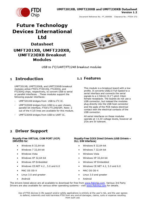
FTDI UMFT201XB、UMFT220XB 和 UMFT230XB 数据手册说明书
UMFT201XB, UMFT220XB and UMFT230XB DatasheetVersion 1.2Document Reference No.: FT_000506 Clearance No.: FTDI# 272 Future TechnologyDevices InternationalLtdDatasheetUMFT201XB, UMFT220XB,UMFT230XB BreakoutModulesUSB to I2C/UART/FT1248 breakout modules1IntroductionUMFT201XB, UMFT220XB, and UMFT230XB breakoutmodules utilize FTDI’s FT201XQ, FT220XQ, andFT230XQ chips, respectively, to convert USB to serial or parallel interfaces. . These modules support thefollowing popular interfaces:-UMFT201XB bridges from USB to I2C IC.-UMFT220XB bridges from USB to a user chosen, parallel bit interface, FTDI’s FT1248/SPI. Note: 2out of the 4 I/0 lines are available for this module.-UMFT230XB bridges from USB to UART IC. 1.1FeaturesThis module is a breakout board with a lowprofile. It converts USB2.0 Full-Speed to aserial interface and connects the serialsignals to a 2.54mm (0.1”) pitch 10pinfemale receptacle. The boards do not use aUSB connector, but instead the modulesplug directly into the USB host connectorand the pads of the PCB makes electricalcontact with the electrical contacts of theUSB connector.All serial interfaces on these modulesoperate at +3.3V voltage levels, however allI/Os are 5V tolerant.2Driver SupportRoyalty-Free VIRTUAL COM PORT (VCP) DRIVERS for:∙Windows 8 32,64-bit∙Windows 7 32,64-bit∙Windows Vista∙Windows XP 32,64-bit∙Windows XP Embedded∙Windows 4.2 , 5.0 and 6.0 ∙MAC OS OS-X∙Linux 3.0 and greater∙Android Royalty-Free D2XX Direct Drivers (USB Drivers + DLL S/W Interface):∙Windows 8 32,64-bit∙Windows 7 32,64-bit∙Windows Vista∙Windows XP 32,64-bit∙Windows XP Embedded∙Windows 4.2, 5.0 and 6.0∙MAC OS OS-X∙Linux 3.0 and greater∙AndroidThe drivers listed above are all available to download for free from . Various 3rd Party Drivers are also available for various other operating systems - visit for details.3Ordering InformationTable of Contents1Introduction (1)1.1Features (1)2Driver Support (1)3Ordering Information (2)4Signals and Configurations (4)4.1UMFT-XB Module Pin Outs (4)4.2Signal Descriptions (4)4.3UMFT201XB CN2 Signal Descriptions (5)4.4UMFT220XB CN2 Signal Descriptions (5)4.5UMFT230XB CN2 Signal Descriptions (6)4.6CBUS Signal Options (6)4.7Configuring the MTP ROM (7)5Module Dimensions (8)6IC Package Markings (8)7UMFT-XB-WE Module Wire Connections (9)7.1UMFT201XB-WE Wire Connections (9)7.2UMFT220XB-WE Wire Connections (10)7.3UMFT230XB-WE Wire Connections (10)8Module Circuit Schematics (11)8.1UMFT201XB Schematic (11)8.2UMFT220XB Schematic (11)8.3UMFT230XB Schematic (12)9Environmental Compliances (12)10Internal MTP ROM Configuration (13)11Contact Information (14)Appendix A - List of Figures and Tables (15)Appendix B: Revision History (16)4 Signals and ConfigurationsFor all three modules, CN1 connects directly to a USB host or HUB port, or can be connected to a USB extension cable. This connects the USB data signals, 5V USB Bus power and GND. When connecting these modules to a USB host or HUB the USB signal pads should be facing upwards, and when connecting to vertical connector the USB signal pad should be facing right. If the module is plugged in the wrong way, no contact will be made between PCB and HUB, no damage will occur from plugging the module in upside down.4.1UMFT-XB Module Pin Outs4.2 Signal Descriptions4.3UMFT201XB CN2 Signal Descriptions4.4UMFT220XB CN2 Signal Descriptions4.5UMFT230XB CN2 Signal Descriptions4.6CBUS Signal OptionsFor further information on CBUS options, please refer to the relevant x-chip datasheet.* PWREN# must be used with a 10kΩ resistor pull up.**When in USB suspend mode the outputs clocks are also suspended.***The number of CBUS pins available varies for the three different modules.4.7Configuring the MTP ROMThe IC on each of the modules contains an embedded MTP memory that can be used to specify the functions of the CBUS pins, the current drive on each signal pin, current limit for the USB bus and the descriptors of the device. For details on using the MTP ROM/EEPROM programming utility FT_PROG, please see the FT_PROG User Guide.When programming the MT memory please note:i)The Max Bus Power setting of the MTP ROM should specify the maximum current to be drawn fromthe USB host/hub when enumerated. For high-powered USB devices the current limit whenenumerated is between 100mA and 500mA, for low-powered USB devices the current limit is100mA.5Module DimensionsTolerance +/-0.1mm2.3Figure 5.1 UMFT-XB Module DimensionsThe UMFT201XB, UMFT220XB and UMFT230XB modules are mechanically identical. Figure 5.1 Uses UMFT230 to illustrate the mechanical details.6IC Package MarkingsThe date code format is YYXX where XX = 2 digit week number, YY = 2 digit year number. This is followed by the revision letter.The code XXXXXXX is the manufacturing LOT code.FTDIXXXXXXXXXXFT201XQ 51YYWW-D8127UMFT-XB-WE Module Wire Connections7.1 UMFT201XB-WE Wire ConnectionsBLACKBROWN RED ORANGE YELLOW GREEN GREY PURPLE BLUE WHITEFigure 7.1 UMFT201XB-WE Wire Connections (numbers refer to pad numbers on the PCB)Figure 6.1 illustrates the –WE product as a cable. This is only for illustration purposes. The wire ended product consists of individual wires – not a cable7.2 UMFT220XB-WE Wire ConnectionsBLACKBROWN RED ORANGE YELLOW GREEN GREY PURPLE BLUE WHITEFigure 7.2 UMFT220XB-WE Wire Connections (numbers refer to pad numbers on the PCB)Figure 6.2 illustrates the –WE product as a cable. This is only for illustration purposes. The wire ended product consists of individual wires – not a cable7.3UMFT230XB-WE Wire ConnectionsBLACKBROWN RED ORANGE YELLOW GREEN GREY PURPLE BLUE WHITEFigure 7.3 UMFT230XB-WE Wire Connections (numbers refer to pad numbers on the PCB)Figure 6.3 illustrates the –WE product as a cable. This is only for illustration purposes. The wire ended product consists of individual wires – not a cable8Module Circuit Schematics 8.1UMFT201XB SchematicFigure 8.1 UMFT201XB Circuit Schematic8.2UMFT220XB SchematicFigure 8.2 UMFT220XB Circuit Schematic8.3UMFT230XB SchematicFigure 8.3 UMFT230XB Circuit Schematic9Environmental CompliancesThe UMFT-XB modules exclusively use lead free components, and are fully compliant with European Union directive 2002/95/EC.10Internal MTP ROM ConfigurationFollowing a power-on reset or a USB reset the FT-X chips will scan its internal MTP ROM and read the USB configuration descriptors stored there. The default values programmed into the internal MTP ROM in the FT201/220/230XB modules is shown in Table 10.1.The internal MTP ROM in the FT-X chip can be programmed over USB using the utility program FT_PROG. FT_PROG can be downloaded from the . Users who do not have their own USB vendor ID but who would like to use a unique Product ID in their design can apply to FTDI for a free block of unique PIDs. Contact FTDI Support(*********************)forthisservice.11Contact InformationHead Office – Glasgow, UKUnit 1, 2 Seaward Place, Centurion Business Park Glasgow G41 1HHUnited KingdomTel: +44 (0) 141 429 2777Fax: +44 (0) 141 429 2758E-mail (Sales) *******************E-mail (Support) *********************E-mail (General Enquiries) ******************* Branch Office – Taipei, Taiwan2F, No. 516, Sec. 1, NeiHu RoadTaipei 114Taiwan , R.O.C.Tel: +886 (0) 2 8797 1330Fax: +886 (0) 2 8751 9737E-mail (Sales) **********************E-mail (Support) ************************ E-mail (General Enquiries) **********************Branch Office – Hillsboro, Oregon, USA 7130 SW Fir LoopTigard, OR 97223USATel: +1 (503) 547 0988Fax: +1 (503) 547 0987E-Mail (Sales) *********************E-Mail (Support) *********************** E-Mail (General Enquiries) *********************Branch Office – Shanghai, ChinaRoom 1103, No. 666 West Huaihai Road, Shanghai, 200052ChinaTel: +86 (0)21 6235 1596Fax: +86 (0)21 6235 1595E-mail (Sales) *********************E-mail (Support) *********************** E-mail (General Enquiries) *********************Web SiteDistributor and Sales RepresentativesPlease visit the Sales Network page of the FTDI Web site for the contact details of our distributor(s) and sales representative(s) in your country.System and equipment manufacturers and designers are responsible to ensure that their systems, and any Future Technology Devices International Ltd (FTDI) devices incorporated in their systems, meet all applicable safety, regulatory and system-level performance requirements. All application-related information in this document (including application descriptions, suggested FTDI devices and other materials) is provided for reference only. While FTDI has taken care to assure it is accurate, this information is subject to customer confirmation, and FTDI disclaims all liability for system designs and for any applications assistance provided by FTDI. Use of FTDI devices in life support and/or safety applications is entirely at the u ser’s risk, and the user agrees to defend, indemnify and hold harmless FTDI from any and all damages, claims, suits or expense resulting from such use. This document is subject to change without notice. No freedom to use patents or other intellectual property rights is implied by the publication of this document. Neither the whole nor any part of the information contained in, or the product described in this document, may be adapted or reproduced in any material or electronic form without the prior written consent of the copyright holder. Future Technology Devices International Ltd, Unit 1, 2 Seaward Place, Centurion Business Park, Glasgow G41 1HH, United Kingdom. Scotland Registered Company Number: SC136640Appendix A - List of Figures and TablesList of FiguresFigure 5.1 UMFT-XB Module Dimensions (8)Figure 7.1 UMFT201XB-WE Wire Connections (numbers refer to pad numbers on the PCB) (9)Figure 7.2 UMFT220XB-WE Wire Connections (numbers refer to pad numbers on the PCB) (10)Figure 7.3 UMFT230XB-WE Wire Connections (numbers refer to pad numbers on the PCB) (10)Figure 8.1 UMFT201XB Circuit Schematic (11)Figure 8.2 UMFT220XB Circuit Schematic (11)Figure 8.3 UMFT230XB Circuit Schematic (12)List of TablesTable 4.1 Module PinOut List (4)Table 4.2 CN1 PinOut Description (4)Table 4.3 I2C Module Pin Out Description (5)Table 4.4 FT1248 Module Pin Out Description (5)Table 4.5 UART Module Pin Out Description (6)Table 4.6 CBUS Configuration Control (7)Table 10.1 Default Internal MTP ROM Configuration (13)Appendix B: Revision HistoryDocument Title: UMFT201XB, UMFT220XB and UMFT230XBDocument Reference No.: FT_000506Clearance No.: FTDI# 272Product Page: /FT-X.htmDocument Feedback: Send FeedbackVersion 1.0 Initial Datasheet Created 09/02/12 Version 1.1 Updated Photos and added Window 8 to driver support list 31/01/13 Version 1.2 Updated -01 part number 03/07/2015。
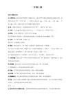
滚子链a、b系列区别及链条标准识别
--------------------------------------------------------------------------------------------------------------------------
大多数链条已列为国际标准,发达国家国家标准或中国国家标准,
(13)MR系列
可锻铸铁滚子链 M—malleable R—Roller chain
(14)TOP系列
平顶链,例如:
TT型,TT635—普通型平顶链,板条宽63.5
TS型,TS550—带平顶的钢滚子链,板条宽55.0
TP型,TP762—平顶板为聚醛树脂,基础链为弯板链,板条宽76.2
例如:SC3即CL06齿形链,节距为9.525
(5)C系列
输送链 C—Conveyor
例如:C2040即08A双节距输送链
C2040 SL SL—Small roller 小滚子
C2060L L—Large roller 大滚子
CA650 C—Conveyor A—Agriculture,农机输送链小滚子型
(12)WR系列
管钳链 WR—Wrench chain
例如:50WR即节距15.875管钳链
3、采用汉语拼音的链号
(1)BS系列
倍速链 B——Bei S——Su
例如:BS25——C210A 即C2050W、10A双节距倍速链
(2)LT系列
立体车库链 L——Li T——Ti
高速齿形链 Hy—Heavy duty, Hight Speed
Vo—Involute
(10)PIV系列
智能机器人视觉感知系统的设计研究

图3图像信号处理系统模块框图 基于图像信号数据量的庞大以及处理速度、特有的算法等原因,系统 选用 的DSP芯 片是 TMs320 VC5509 ^。 因为本系统用的DSP芯片不具有FLASH结构,不能进行在线编程,一旦 系统掉电所有的数据将丢失。针对这个原因,采用了一片具有SPI 总线接口 的FLASH存储器SA25F005,通过这个 存储器,加上DSP芯片本身 具有的 BOOTLOAD:摸式,这样当DSP上屯复位后,通过采样DSP的GPI OO~GPl 03确定 DSP 的加 载模式 ,利 用DS P的多 功能 口与F LASH存储器 进行 数据 交换 。 另一方 面,由于 DSP的TMS320VC5509A的内部存 储资源为 :128KX 16 bi t 片内RAM。DSP在图像处理的过程中有大量的中间数据需要存储,而片 内的 资源 又比 较有限 ,所 以本 系统采 用了 一片 SDRAM作为 片外数 据存 储用 , 缓解系统对Ds P内部资源应用的紧张。在选用存储器时考虑到性价比等因 素 ,采 用YS DRAM型, 这种 芯 片的 典型 特点 是性 价比 高。 圈、 视童 矗知 系统较 件控 翻设 计
图像信号处理部分包括DSP芯片部分电路、用于Bo ot l oad 的f l ash 存储
器电 路和 对处理 时进 行数据 存储的 SDRAM电路 。 使用液晶显示是本系统与其它设计系统相比较特别的地方,目的一是
为了直观显示图像传感器采集图像的效果;二是在视觉系统的目标物体的 跟踪设计时,能够直观的实时看到视觉系统对目标跟踪的状态。由于本系
统采用了类似于足球机器人的颜色识别方法,即通过对目标物体的颜色识 别来达到对目标物体进行判别的一个识别模式,所以在显示上采用的是一 个彩 色TFT液 晶来达到 这个目的 。
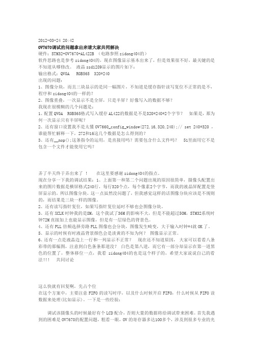
OV7670调试的问题
2012-03-24 20:42OV7670调试的问题拿出来请大家共同解决硬件:STM32+OV7670+AL422B (电路参照zidong404的)软件思路也是参考zidong404的,现在图像显示基本出来了,但是效果很不好,最关键的是不知道从哪修改。
液晶ssd1289显示的图片如下:输出格式:QVGA RGB565 320*240出现的问题:1、图像分块,而且三块显示的是同一幅图片,不知道是缓存指针读写复位不正常的是不,程序和zidong404的一样的?2、图像重叠,一次显示不是全屏,只是半屏?好像写入的数据不够?我现在很模糊的几个问题是:1、配置QVGA RGB565格式写入缓存AL422的数据是不是320*240*2个字节?如果是,那为何一次显示只有半屏呢?2、还有窗口设置我不是太懂OV7660_config_window(272,16,320,240);// set 240*320 ,谁能帮忙解释一下,272和16这几个数据是怎么得到的?3、还有__nop();这条指令的运用,是直接用吗?需要包含什么文件吗? 51里面用它不是包含一个文件才能使用它吗?弄了半天终于弄出来了!在这里要感谢zidong404的指点。
现在分享一下我的调试结果:1、上面第一和第二个问题出现的原因很简单,摄像头配置出来的图片数据是横屏格式240行,每行320个点,每个像素2个字节,而我的液晶屏配置是竖屏显示的,所以图像分块。
这一点虽然没问题了,但我感觉这样的话图像分块应该是不规则的,而结果是三块一样的图像。
2、还有读写指针复位,如果写指针复位延时不够也会图像分块。
3、还有XCLK时钟我的是8M,这个我试了36M的影响不大,但是不能超过50M,STM32系统时钟72M直接加上也能显示图像,但是有一层绿色的背景色。
4、还有PLL倍频选择旁路PLL图像也会分块,图像发生畸变,大于输入时钟*4就OK了。
5、显示的时候有时液晶背景颜色会是淡黄的不知为何?图像显示正常。
滚子链a、b系列区别及链条标准识别
滚子链a、b系列区别及链条标准识别滚子链 a、b系列区别及链条标准识别精密滚子链分为A、B两大系列。
A系列是符合美国链条标准的尺寸规格:B系列是符合欧洲(以英国为主)链条标准的尺寸规格,相互之间除节距相同外,其他方面有本系列自身的特点,主要区别为:1)A系列产品内链板与外链板厚度相等,通过不同的调试取得静强度的等强度效果。
B系列产品内链板与外链板调试相等和,通过不同的百度取得静强度的等强度效果。
2)A系列各元件主要尺寸与节距有一定的比例。
如:销轴直径=(5/16)P,滚子直径=(5/8)P,链板厚度=(1/8)P(P为链条节距)等。
而B系列零件主要尺寸与节距不存在明显比例。
3)同档的链条破断载荷值比较,B系列除12B规格低于A系列外,其余各档规格均同档的A系列产品。
该产品标准等效采用国际标准ISO9606:1994,其产品规格、尺寸和搞拉载荷值等与国际标准完全一致。
结构特点:链条由内链板,滚子和套筒组成的内链节与由外链板、销轴组成的外链节交替铰接而成。
产品选用可按功率曲线选用所需链条规格。
如按计算选用时,安全系数应大于3。
--大多数链条已列为国际标准,发达国家国家标准或中国国家标准,这些链条的链号标识,不难从标准中查到。
然而在链条国际贸易交往中,常常流行着美国、日本、德国、意大利、比利时等国家的链条企业链号,使得我们的链条企业家们望之茫然无对,束手无策。
故笔者就此做些引导,对于从事链条贸易的诸位,或许稍有裨益。
1、带有前缀的链号(1)RS系列直板滚子链R-RollerS-Straight例如:RS40即08A滚子链(2)RO系列弯板滚子链R-RollerO-Offset例如:RO60即12A弯板链(3)RF系列直边滚子链R-RollerF-Fair例如:RF80即16A直边滚子链(4)SC系列齿形链(无声链)S-SilentC-Chain来自ANSIB29.2M齿形链和链轮标准。
例如:SC3即CL06齿形链,节距为9.525(5)C系列输送链C-Conveyor例如:C2040即08A双节距输送链C2040SLSL-Smallroller小滚子C2060LL-Largeroller大滚子CA650C-ConveyorA-Agriculture,农机输送链小滚子型 Smalirollertype 大滚子型Largerollertype(6)L系列板式链L-Leafchain例如AL422即A型板式链,节距12.7,组合2×2美国链号1975年取消BL546即B型板式链,节距15.875,组合4×6美国链号 LH0822即BL422,H-Heavy重型ISO链号LL1044,L-Light轻型ISO链号(7)M系列公制链条M-Metricmeasure 例如:M20内节内宽为1530mm的滚子链,有7种公制节距。
单片机中实现数字图像压缩的算法研究

man编码函数等关键函数 ,并对其算法加以改进 ,对其复杂性进行了可靠的分析 。
关键词 :图像压缩 ; DCT; Huffman;数字图像 ; JPEG
中图分类号 : TP393. 02
文献标识码 : A
引言
目前实现图像压缩的方法很多 , 但是主要集中在 DSP和 PC机中进行 ,而在单片机中实现数字图像压缩 , 则主要存在内存容量和计算速度两大问题 。随着单片 机技术和存储技术的发展 ,在单片机中实现数字图像压 缩成为可能 。由于数字图像的数据量很大 , 远距离成 像 、传输等就必须对其进行压缩编码 。利用单片机实现 数字图像压缩 ,提供高可靠性 、高性价比的应用系统 ,不 仅在军事侦察 、抢险救灾 、气象擦测等领域有着广泛应 用 ,而且在工业检测领域 (如外观在线检测 、特殊图形 检测等 ) 、高温作业等领域有着更加广泛的应用 。
因此 , 我们在硬件设计中设计了两片 F IFO 芯片 L4V8M440,在具体实现的过程中 ,根据 F IFO 芯片的特 点 ,我们每次从 L4V8M440 读入一定量的图像数据 ,经 过 DCT处理后存放在 C8051F120 的内部 ,同时对其进 行统计 ,当 DCT完成第一遍后 ,统计也就完成 。第二遍 时对其建立 Huffman树并进行编码 ,进行数据压缩 ,形 成 JPEG图像数据存放在另一片 L4V8M440 中 ,从而完 成了对整个图像数据的压缩和编码 。
收稿日期 : 2009211214 基金项目 : 863国家重点基金项目 (2008AA11A134) 作者简介 :王 晓 (19612) ,男 ,四川富顺人 ,副教授 ,硕士 ,主要从事计算机应用方面的研究 。
第 23卷第 1期 王 晓等 :单片机中实现数字图像压缩的算法研究
盲人智能过街辅助系统设计方案

盲人智能过街辅助系统设计-机械制造论文盲人智能过街辅助系统设计王少华1,2吴向东1潘金平1朱磊1覃人波1(1.天津职业技术师范大学,中国天津300222;2.天津市交通安全与控制协同创新中心,中国天津300222)【摘要】介绍了基于飞思卡尔K60单片机的盲人智能过街辅助系统。
在详细分析盲人过街需求的基础上,采用IAR6.3开发平台进行程序设计,基于飞思卡尔K60芯片设计硬件模块,进行超声波和红外测障测距,通过OV7725鹰眼摄像头实现斑马线视频图像采集。
实验室实验结果表明,该系统能够保证盲人走在斑马线中间区域并可避免与障碍物相撞,可有效应用于盲人过街辅助。
关键词盲人;过街;辅助系统;飞思卡尔K60【Abstract】ThispaperintroducesanintelligentintersectioncrossingassistsystemforThe BlindbasedonFreescaleK60.Onthebasisofadetailedanalysisoftheneedsoft heblindmanwhentheyacrossthestreet,ituseIAR6.3developmentplatformf orprogramming,designbasedonhardwaremodulebasedonFreescaleK60c hip,detectswhetherthereexistobstacleswithinadistanceinfrontbymeansofultr asonicandinfraredandachievezebravideoimagebyOV7725Hawkeyecamer a.TheLaboratorytestresultsshowthatthesystemcouldensurethatblindpeo plecanwalkonthecenterofzebraandavoidobstacles,willbehelpfultoassistbl indpeopletoacrossthestreet.【Keywords】Theblind。
单片机应用系统中利用FIFO芯片AL422B实现数字图像的静态存储

在MCS -51系列单片机应用系统中利用FIFO 芯片AL422B实现数字图像的静态存储杨维剑(四川理工学院(高专校区)四川自贡64300)【摘 要】 本文论述了在MCS -51单片机应用系统中利用FIFO 芯片AL422B 实现数字图像的静态存储的原理、方法和系统实现和相应的软件设计。
【关键字】 单片机、数字图像、FIFO 一、引言在MCS -51单片机应用系统中,由于速度及程序存储器和数据存储器的寻址空间的限制,要存储每秒30帧,640×480像素大小的一副图像,是相当困难的。
而FIFO 芯片AL422B 的出现,解决了这一难题。
本文就在MCS -51单片机应用系统中用芯片AL422B 实现数字图像的静态存储的原理、方法和具体实现做了较为详细的论述。
二、FIFO 芯片A L422B 和图像芯片OV 7620/OV 71201、FIFO 芯片A L422BA L422B 是AverLogic 公司推出的一个存储容量为393216字节×8位的FIFO 存储芯片。
由于其所有的寻址、刷新等操作都由集成在芯片内部的控制系统完成,内部功能框图如图一。
图一 A L422B 内部功能图A L422B 其主要特点是:A L422B 的存储体为3M 位(393216字节×8位); 可以存储VG A 、CCIR 、NTSC 、PA L 和H DTV 等制式一帧图形的信息;独立的读写操作,可以接受不同的I/O 速率; 高速异步串行存取 读写周期为20ns; 存取时间:15ns 内部DRAM 自刷新;输出准许控制(数据跳越) 5V 或3.3V 电源 标准28芯SOP 封装2、图像芯片OV 7620/OV 7120OV 7620/OV 7120是Omni Vision T echnologies ,inc.2000年推出的高度集成、高分辨率(640×480)、隔行/逐行扫描、CMOS 的彩色/黑白的图像采集芯片。
基于单片机的图像采集系统设计

目录0 前言 (1)1总体方案设计 (1)2 系统硬件设计 (3)3 软件设计 (9)3.1软件设计概述 (9)3.2程序流程图 (9)3.3子程序模块设计 (10)4系统调试及结果分析 (11)5结论及进一步设想 (14)参考文献 (14)课程设计体会 (15)附录1 元件清单 (16)附录2 系统电路图 (17)附录3 源程序 (18)基于单片机的图像采集系统刘杰薇沈阳航空航天大学自动化学院摘要:传统的工业级图像处理采集系统大多是由CCD摄像头、图像采集卡和PC机组成,虽已得到了广泛的应用,但是它具有结构复杂,成本高,体积大,功耗大等缺点。
随着单片机的迅速发展,开发一种智能控制及智能处理功能的微型图像处理采集系统成为可能,并且也克服了传统图像处理采集系统的诸多缺点。
本设计的图像采集系统采用AT89C51单片机为中心器件,利用74LS373寄存器、62256存储器。
将软、硬件有机地结合起来,使得系统能够实现对摄像头传输的图像信号的采集,并保存在外置存储芯片中。
其中软件系统采用C语言编写程序,包括延时程序、地址顺延程序等,硬件系统利用PROTEUS强大的功能来实现,简单切易于观察,在仿真中就可以观察到实际的工作状态。
关键字:单片机;图像采集;数字摄像头0前言近年来随着科技的飞速发展,单片机的应用正在不断的走向深入,同时带动着传统控制检测日新月异更新。
在实时检测和自动控制的单片机应用系统中,单片机往往是作为一个核心部件来使用,仅单片机方面的知识是不够的,还要根据具体的硬件结构,以及针对具体的应用对象的软件结合,加以完善。
数字图像采集由于其大数据量通常采用DSP等高速处理器来实现。
在某些领域方面图像实时性的要求并没有那么高,因此,本文采用STC89C51单片机作为控制器进行图像采集。
1总体方案设计方案一:由于C51单片机的RAM存储容量有限,而且受到C51单片机的IO工作频率的限制,直接通过C51单片机采集完整一帧的数字信号很难实现。
基于STM32的嵌入式远程视频监控系统设计

基于STM32的嵌入式远程视频监控系统设计马跃辉;冀保峰;程一淼;高宏峰【摘要】随着工业技术的不断发展,以及人对安全防范意识的逐渐加强,视频监控系统已经成为人们在生产、生活中必不可少的一部分.随着计算机技术的发展、宽带的普及、图像处理技术的提高,本文设计了基于STM32的远程监控系统,以OV7670摄像头模块采集图像信息,通过ENC28J60模块将图像信息传输到以太网,同时利用SD卡实时存储图像,利用PC机或手机作为监控终端,可以随时随地的查看监控状况.该系统具有低功耗,成本低,方便可行,有广泛的应用前景.【期刊名称】《山西电子技术》【年(卷),期】2018(000)001【总页数】4页(P52-55)【关键词】STM32;远程监控;以太网;ENC28J60【作者】马跃辉;冀保峰;程一淼;高宏峰【作者单位】河南科技大学信息工程学院,河南洛阳471023;河南科技大学信息工程学院,河南洛阳471023;电子科技大学航空航天学院,四川成都611731;河南科技大学信息工程学院,河南洛阳471023;河南科技大学信息工程学院,河南洛阳471023【正文语种】中文【中图分类】TP277;TP3930 引言国内外的视频监控行业经历了本地模拟信号监控系统、基于PC插卡的数字监控系统和基于嵌入式技术的数字监控系统的发展过程。
目前已经发展到第三个阶段,正大规模向着嵌入式技术的数字监控方向发展,视频监测系统已经成为当今可视化领域的一个新的开发热点。
随着以太网的覆盖面越来越广,借助以太网能够满足用户直观实时地且不受地点限制观看监控画面,相比较于传统视频监控系统,嵌入式视频监控明显具有更高的可靠性和便利性,能够给用户带来更多舒适、安全和智能的生活体验。
1 系统总体设计系统总体设计结构如图1所示,主要由STM32F103ZET6主控制器和其他子模块组成。
主控制器主要用于处理和分析传感器信息以及以太网操作信息,控制内部运行代码及SD存储。
基于STM32的可穿戴导盲系统设计

计算机工程应用技术本栏目责任编辑:梁书基于STM32的可穿戴导盲系统设计黎剑彬,吴中健,林祥辉,黄祖仪,阳韬(华南理工大学广州学院,广东广州510800)摘要:为解决盲人的日常生活出行问题,设计了一个基于STM32单片机的可穿戴式导盲器,系统运用了红外测距仪、超声波传感器、摄像头、陀螺仪、麦克风等,无线通信选择蓝牙,通过耳机和马达振动进行提醒,红外测距仪、超声波传感器、摄像头、陀螺仪、麦克风、百度地图模块等,无线通信选择蓝牙,实现对物体的识别,对路况的实时分析探测,并过耳机和马达振动进行提醒等功能。
关键词:可穿戴;导盲系统;无线通信;实时定位中图分类号:TP311文献标识码:A 文章编号:1009-3044(2021)10-0235-03开放科学(资源服务)标识码(OSID ):Design of Wearable Blind Guide System Based on STM32LI Jian-bin,WU Zhong-jian,LIN Xiang-hui,HUANG Zu-yi,YANG Tao(Guangzhou College of South China University of Technology,Guangzhou 510800,China)Abstract:In order to solve the daily travel problems of the blind,a wearable blind guide based on STM32microcontroller is de⁃signed.The system uses infrared rangefinders,ultrasonic sensors,cameras,gyroscopes,microphones,etc.,wireless communication selects Bluetooth,through Earphone and motor vibration reminder,infrared rangefinder,ultrasonic sensor,camera,gyroscope,mi⁃crophone,Baidu map module,etc.,wireless communication selects Bluetooth to realize object recognition,real-time analysis and detection of road conditions,and use earphone and motor Vibrate to remind and other functions.Key words:Wearable;Guide system;Wireless communication;Real-time positioning据2019年世卫组织发布的首份《世界视力报告》其中表明全球至少有22亿人视力受损或失明,而中国在2016年,视障人数的数量已经迅速增长到了1731万人,大约每八十个人就有一名失明人士,我国的盲道设计得不合理、被占用、被破坏等一系列原因,导致视障人士的外出变得更加的困难,因此我们想设计制造一个可穿戴的导盲器,通过红外传感器的检测距离,计算机视觉对物体的检测,通过单片机、系统对各种数据的处理,分析出路面的实际实时状况,通过语音和振动等方法告知有视力障碍的使用者,最终达到安全顺利的出行。
中国传统文化人生价值取向对大学生青年的引导意义
进而促进大学生青年成长成才。
探测频率达
使用
指令;
5s
控制指令唤醒
宽工作电压范围
鹰眼摄像头
本系统采用以
图3视频图像上位机软件界面
3结语
为了辅助盲人过街,十分有必要对斑马线和道路障碍物进行实时
监测。
本文设计了一种基于飞思卡尔K60的智能盲人过街辅助系统,
结果表明,该系统各模块工作正常,能够有效监测障碍物距离,识别障
碍物高度是否高于传感器设置高度,同时,完成了初步的斑马线中线
和安全区域监测。
但本系统只完成了理想条件下的实验室图像处理工
作,还有待于进行不同传感器的数据融合算法设计,以及室外斑马线
实测,才能真正为盲人出行提供辅助。
【参考文献】
[1]王冠生,郑江华,瓦哈甫·哈力克,张洋,姚聚慧.盲人导航路径诱导辅具研究与
应用综述[J].计算机应用软件,2012,29(12):147-151.
[2]王小伟.基于RFID的盲道识别系统设计[D].成都:成都理工大学,2009.
[3]赵晓东.超声波导盲杖的设计[J].山西电子技术,2011(5):19-21.
[4]曹玉珍,刘刚,杨海峰.导盲系统中的道路斑马线识别方法[J].计算机工程与应
用,2008,44(15):177-178.
[5]邱晶晶.多功能导盲装置的若干问题研究[D].郑州:郑州大学,2010.
[6]刘延霞,谷林柱.基于单片机的盲人避障装置的设计[J].软件,2011,32(3):101-
104.
[责任编辑:汤静]
举办毕业生就业创业典型事迹报告会。
视频帧存储器AL422B及其应用
视频帧存储器AL422B及其应用
黄再银
【期刊名称】《中国有线电视》
【年(卷),期】2003(000)006
【摘要】AL422B是一种视频帧存储器,存储容量为384 k×8 bits,存储器结构为先进先出(FIFO),其接口非常简单.介绍了它的性能特点及应用领域,并给出了它在扫描率转换器中的应用实例.
【总页数】2页(P59-60)
【作者】黄再银
【作者单位】解放军广州通信学院,广东,广州,510502
【正文语种】中文
【中图分类】TN948.57
【相关文献】
1.FIFO芯片AL422B在视频系统中的应用 [J], 郭照南;李儒峰
2.帧存储器AL440B及其在视频回放系统中的应用 [J], 平聪慧;曾峦;张天平
3.帧存储器容量受限条件下编码视频码率变换的研究 [J], 王建松;俞斯乐
4.变电所视频帧存储器地址生成器的设计 [J], 樊志华;洪君
5.视频处理芯片中的高速帧存储器接口设计 [J], 吴勇;郑南宁;张光烈;梁寒
因版权原因,仅展示原文概要,查看原文内容请购买。
标准型号链条参数表
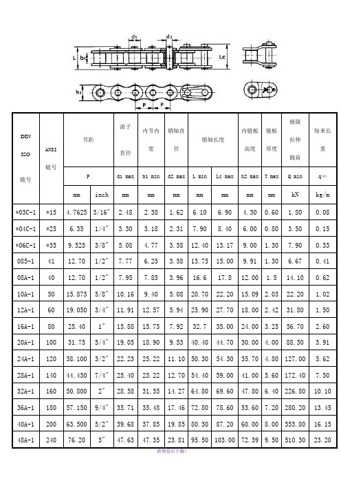
DINISO 链号ANSI链号节距滚子直径内节内宽销轴直径销轴长度内链板高度链板厚度极限拉伸载荷每米长重P d1 max b1 min d2 max L min Lc max h2 max T max Q min q≈mm inch mm mm mm mm mm mm mm kN kg/m*03C-1*15 4.76253/16" 2.48 2.38 1.62 6.10 6.90 4.300.60 1.800.08 *04C-1*25 6.351/4" 3.30 3.18 2.317.908.40 6.000.80 3.500.15 *06C-1*359.5253/8" 5.08 4.77 3.5812.4013.179.00 1.307.900.33 085-14112.701/2"7.77 6.25 3.5813.7515.009.91 1.30 6.670.41 08A-14012.701/2"7.957.85 3.9616.617.812.00 1.514.100.62 10A-15015.8755/8"10.169.40 5.0820.7022.2015.09 2.0322.20 1.02 12A-16019.0503/4"11.9112.57 5.9425.9027.7018.00 2.4231.80 1.50 16A-18025.401"15.8815.757.9232.735.0024.00 3.2556.70 2.60 20A-110031.755/4"19.0518.909.5340.4044.7030.00 4.0088.50 3.91 24A-112038.1003/2"22.2325.2211.1050.3054.3035.70 4.80127.00 5.62 28A-114044.4507/4"25.4025.2212.7054.4059.0041.00 5.60172.407.50 32A-116050.8002"28.5831.5514.2764.8069.6047.80 6.40226.8010.10 36A-118057.1509/4"35.7135.4817.4672.8078.6053.607.20280.2013.45 40A-120063.5005/2"39.6837.8519.8580.3087.2060.008.00353.8016.15 48A-124076.203"47.6347.3523.8195.50103.0072.399.50510.3023.20A系列链条标准参数B系列链条标准参数DIN ISO 链号节距滚子直径内节内宽销轴直径销轴长度内链板高度链板厚度极限拉伸载荷每米长重P d1 max b1 min d2 max L min Lc max h2 max t/T max Q min q≈mm inch mm mm mm mm mm mm mm kN kg/m03B-104B-1 6.00 4.00 2.80 1.85 6.807.80 5.000.60 3.000.11 05B-18.00 5.00 3.00 2.318.208.907.100.80 5.000.20 *06B-19.5253/8" 6.35 5.72 3.2813.1514.18.20 1.309.000.41 08B-112.701/2"8.517.75 4.4516.7018.2011.80 1.6018.000.69 10B-115.8755/8"10.169.65 5.0819.5020.914.70 1.7022.40.93 12B-119.0503/4"12.0711.68 5.7222.5024.2016.00 1.8529.0 1.15 16B-125.401"15.8817.028.2836.1037.4021.00 4.15/3.160.0 2.71 20B-131.755/4"19.0519.5610.1941.3045.0026.40 4.5/3.595.00 3.70 24B-138.1003/2"25.4025.4014.6353.4057.8033.20 6.0/4.8160.07.10 28B-144.4507/4"27.9430.9915.9065.1069.5036.707.5/6.0200.08.50 32B-150.8002"29.2130.9917.8166.0071.042.007.0/6.0250.010.25板式链组合形式图例1. AL板式链系列2. 轻系列板式链LL系列3. 重系列板式链LH(BL)系列(注:可编辑下载,若有不当之处,请指正,谢谢!)。
- 1、下载文档前请自行甄别文档内容的完整性,平台不提供额外的编辑、内容补充、找答案等附加服务。
- 2、"仅部分预览"的文档,不可在线预览部分如存在完整性等问题,可反馈申请退款(可完整预览的文档不适用该条件!)。
- 3、如文档侵犯您的权益,请联系客服反馈,我们会尽快为您处理(人工客服工作时间:9:00-18:30)。
AL422 Data Sheets(Revision V1.1)AL422 Amendments (Since April 2, 1999)05-13-99 DC/AC characteristics (including current consumption) updated.07-02-99 Pinout diagram (5.0) and DC external load (7.4) modified.08-03-99 Description about TST pin added in sections 6.0 & 8.1.09-02-99 8.3.2 rewritten.10-26-99 Capacitance provided in the AC characteristics section.12-15-99 Remove TST pin restriction.01-18-01 1. Revised section “8.3.2 Read Enable during Reset Cycles” to “8.3.2 The Proper Manipulation of FIFO Access”.2. Add section “8.3.3 Single Field Write with Multiple Read Operation”3. Add section “8.3.4 One Field Delay Line (The Old Data Read)”AL422 3M-Bits FIFO Field MemoryContents:1.0 Description________________________________________________________________42.0 Features___________________________________________________________________43.0 Applications________________________________________________________________44.0 Ordering Information________________________________________________________45.0 Pinout Diagram____________________________________________________________56.0 Pin Description_____________________________________________________________57.0 Electrical Characteristics_____________________________________________________67.1 Absolute Maximum Ratings________________________________________________________67.2 Recommended Operating Conditions________________________________________________67.3 DC Characteristics_______________________________________________________________67.4 AC Characteristics_______________________________________________________________77.5 Timing Diagrams_________________________________________________________________98.0 Functional Description______________________________________________________138.1 Memory Operation______________________________________________________________148.2 5V and 3.3V applications_________________________________________________________158.3 Application Notes_______________________________________________________________168.3.1 Irregular Read/Write_________________________________________________________________168.3.2 The Proper Manipulation of FIFO Access_________________________________________________178.3.3 Single Field Write with Multiple Read Operation___________________________________________178.3.4 One Field Delay Line (The Old Data Read)_______________________________________________179.0 Mechanical Drawing_______________________________________________________191.0 DescriptionThe AL422 consists of 3M-bits of DRAM, and is configured as 393,216 words x 8 bit FIFO (first in first out). The interface is very user-friendly since all complicated DRAM operations are already managed by the internal DRAM controller.Current sources of similar memory (field memory) in the market provide limited memory size which is only enough for holding one TV field, but not enough to hold a whole PC video frame which normally contains 640x480 or 720x480 bytes. The AverLogic AL422 provides 50% more memory to support high resolution for digital PC graphics or video applications. The 50% increase in speed also expands the range of applications.2.0 Features• 384K (393,216) x 8 bits FIFO organization • Support VGA, CCIR, NTSC, PAL and HDTV resolutions• Independent read/write operations (different I/O data rates acceptable)• High speed asynchronous serial access• Read/write cycle time: 20ns• Access time: 15ns• Output enable control (data skipping)• Self refresh• 5V or 3.3V power supply• Standard 28-pin SOP package 3.0 Applications• Multimedia systems• Video capture systems• Video editing systems• Scan rate converters• TV’s picture in picture feature • Time base correction (TBC)• Frame synchronizer• Digital video camera• Buffer for communications systems4.0 Ordering InformationPart number Package Power Supply StatusAL422B 28-pin plastic SOP +5/+3.3 volt ShippingAL422V5 28-pin plastic SOP +5 volt Replaced by AL422B AL422V3 28-pin plastic SOP +3.3 volt Replaced by AL422B5.0 Pinout Diagram6.0 Pin DescriptionPin name Pin # I/O type Function DI0~DI7 1~4, 11~14input Data input WCK 9 Input Write clock /WE 5 Input (active low) Write enable /WRST 8 Input (active low) Write reset DO0~DO7 15~18, 25~28Output (tristate)Data output RCK 20 InputRead clock /RE 24 Input (active low) Read enable /RRST 21 Input (active low) Read reset /OE 22 Input (active low)Output enable TST 7 Input Test pin (pulled-down)*VDD 10 5V or 3.3V DEC/VDD 19 Decoupling cap inputGND6, 23GroundDI0DI1DI2DI3/WE GND TST /WRST WCK VDD DI4DI5DI6DI7DO0DO1DO2DO3/RE GND /OE /RRST RCK DEC DO4DO5DO6DO7AL422-04 422B pinout diagram7.0 Electrical Characteristics7.1 Absolute Maximum RatingsRatingsParameterUnit3.3V application 5V applicationV DD Supply Voltage -1.0 ~ +4.5 -1.0 ~ +7.0 VV P Pin Voltage -1.0 ~ +5.5 -1.0 ~ V DD +0.5 VI O Output Current -20 ~ +20 -20 ~ +20 mAT AMB Ambient Op. Temperature 0 ~ +70 0 ~ +70 °CT stg Storage temperature -55 ~ +125 -55 ~ +125 °C7.2 Recommended Operating Conditions3.3V application 5V applicationUnit ParameterMin Max Min Max V DD Supply Voltage +3.0 +3.6 +4.5 +5.25 V V IH High Level Input Voltage +2.0 +5.5 +3.0 V DD +0.5 V V IL Low Level Input Voltage -1.0 +0.8 -1.0 +0.8 V7.3 DC Characteristics(V DD =5V or 3.3V, Vss=0V. T AMB = 0 to 70°C)3.3V application 5V applicationUnit ParameterMin Typ Max Min Typ MaxI DD Operating Current @20MHz - 33 - - 50 - mAI DD Operating Current @30MHz - 45 - - 66 - mAI DD Operating Current @40MHz - 57 - - 82 - mAI DD Operating Current @50MHz - 68 - - 97 - mAI DDS Standby Current - 7 - - 12 - mAV OH Hi-level Output Voltage 0.7V DD- V DD+3.0 - V DD V V OL Lo-level Output Voltage - - +0.4 - - +0.4 VI LI Input Leakage Current -10 - +10 -10 - +10 µAI LO Output Leakage Current -10 - +10 -10 - +10 µA7.4 AC Characteristics(V DD =5V or 3.3V, Vss=0V, T AMB = 0 to 70°C)3.3V application 5V applicationParameterUnitMin Max Min Max T WC WCK Cycle Time 20 1000 20 1000 nsT WPH WCK High Pulse Width 7 - 7 - nsT WPL WCK Low Pulse Width 7 - 7 - nsT RC RCK Cycle Time 20 1000 20 1000 nsT RPH RCK High Pulse Width 7 - 7 - nsT RPL RCK Low Pulse Width 7 - 7 - nsT AC Access Time - 15 - 15 nsT OH Output Hold Time 4 - 4 - nsT HZ Output High-Z Setup Time 3 15 4 15 nsT LZ Output Low-Z Setup Time 3 15 4 15 nsT WRS/WRST Setup Time 5 - 6 - nsT WRH/WRST Hold Time 2 - 3 - nsT RRS/RRST Setup Time 5 - 6 - nsT RRH/RRST Hold Time 2 - 3 - nsT DS Input Data Setup Time 5 - 6 - nsT DH Input Data Hold Time 2 - 3 - nsT WES/WE Setup Time 5 - 6 - nsT WEH/WE Hold Time 2 - 3 - nsT WPW/WE Pulse Width 10 - 10 - nsT RES/RE Setup Time 5 - 6 - nsT REH/RE Hold Time 2 - 3 - nsT RPW/RE Pulse Width 10 - 10 - nsT OES/OE Setup Time 5 - 6 - nsT OEH/OE Hold Time 2 - 3 - nsT OPW/OE Pulse Width 10 - 10 - nsT TR Transition Time 2 20 3 20 nsC I Input Capacitance - 7 - 7 pFC O Output Capacitance - 7 - 7 pF• Input voltage levels are defined as VIH=3.0V and VIL=0.4V.• The read address needs to be at least 128 cycles after the write address. DO external load:7.5 Timing DiagramsWCK/WRSTDI7~0/WE = "L"AL422-05 Write Cycle Timing (Write Reset) Array RCK/RRSTDO7~0/RE = /OE = "L"AL422-07 Read Cycle Timing (Read Reset)RCK/OEDO7~0AL422-09 Read Cycle Timing (Output Enable)/RE = "L"RCK/REDO7~0AL422-08 Read Cycle Timing (Read Enable)/OE = "L"WCK/WEDI7~0AL422-06 Write Cycle Timing (Write Enable)RCK/REDO7~0AL422-14 Read Cycle Timing (RE, RRST)/RRST/OE = "L"WCK/WEDI7~0AL422-15 Write Cycle Timing (WE, WRST)/WRST8.0 Functional DescriptionThe AL422 is a video frame buffer consisting of DRAM that works like a FIFO which is long enough to hold up to 819x480 bytes of picture information and fast enough to operate at 50MHz. The functional block diagram is as follows:The I/O pinouts and functions are described as follows:DI7~DI0 Data Input: Data is input on the rising edge of the cycle of WCK when /WE is pulled low(enabled).DO7~DO0 Data Output: Data output is synchronized with the RCK clock. Data is obtained at therising edge of the RCK clock when /RE is pulled low. The access time is defined from the rising edge the rising edge of the WCK cycle when /WE is pulled low (enabled). The internal write address /WE Write Enable Input: /WE controls the enabling/disabling of the data input. When /WE issignal is fetched at the rising edge of the WCK cycle./RE Read Enable Input: /RE controls the operation of the data output. When /RE is pulled low, output data is provided at the rising edge of the RCK cycle and the internal read address is incremented automatically. /RE signal is fetched at the rising edge of the RCK cycle./OE Output Enable Input: /OE controls the enabling/disabling of the data output. When /OE is pulled low, output data is provided at the rising edge of the RCK cycle. When /OE is pulled high, data output is disabled and the output pins remain at high impedance status. /OE signal is fetched at the rising edge of RCK cycle./WRST Write Reset Input: This reset signal initializes the write address to 0, and is fetched at the rising edge of the WCK input cycle./RRST Write Reset Input: This reset signal initializes the read address to 0, and is fetched at the rising edge of the RCK input cycle.TST Test Pin: For testing purpose only. It should be pulled low for normal applications.DEC: Decoupling cap pin, should be connected to a 1µF or 2.2µF capacitor to ground for 5V application. For 3.3V application, the DEC pin can be simply connected to the 3.3V power with regular 0.1µF bypass capacitor.8.1 Memory OperationInitializationApply /WRST and /RRST 0.1ms after power on, then follow the following instructions for normal operation.Reset OperationThe reset signal can be given at any time regardless of the /WE, /RE and /OE status, however, they still need to meet the setup time and hold time requirements with reference to the clock input. When the reset signal is provided during disabled cycles, the reset operation is not executed until cycles are enabled again. When /WRST signal is pulled low, the data input address will be set to 0 and the data in the Input Buffer will be flushed into memory cell array. When /RRST signal is pulled low, the data output address will be set to 0 and pre-fetch the data from memory cell array to Output Buffer.Write OperationData input DI7~DI0 is written into the write register at the WCK input when /WE is pulled low. The write data should meet the setup time and hold time requirements with reference to the WCK input cycle.Write operation is prohibited when /WE is pulled high, and the write address pointer is stopped at the current position. The write address starts from there when the /WE is pulled low again. The /WE signal needs to meet the setup time and hold time requirements with reference to the WCK input cycle.Read OperationData output DO7~DO0 is written into the read register at the RCK input when both /RE and /OE are pulled low. The output data is ready after T AC (access time) from the rising edge of the RCK input cycle.The read address pointer is stopped at the current position when /RE is pulled high, and starts there when /RE is pulled low again./OE needs to be pulled low for read operations. When /OE is pulled high, the data outputs will be at high impedance stage. The read address pointer still increases synchronously with RCK regardless of the /OE status. The /RE and /OE signals need to meet the setup time and hold time requirements with reference to the RCK input cycle.When the new data is read, the read address should be between 128 to 393,247 cycles after the write address, otherwise the output may not be new data.8.2 5V and 3.3V applicationsThe AL422 can accept either 3.3V or 5V power with slightly different external configuration. The internal voltage regulator can convert 5V power to 3.3V for the embedded DRAM and logic circuitry when 5V power is applied to VDD pin (#10) only and leave the DEC pin (#19) decoupled by a capacitor of 1µF or 2.2µF to ground. The regulator can also be bypassed when 3.3V power is applied to both VDD and DEC pins. In either case the AL422 is 5V or 3.3V I/O tolerant. The 3.3V configuration consumes less power and is free from noise interference from the voltage regulator so may be more ideal for high-speed applications.Please note that using the AL422B with 5V configuration can directly replace the previous AL422V5; using it with 3.3V configuration can directly replace the previous AL422V3. No additional modification is required.The 5V configuration (direct replacement of the previous AL422V5) is as follows:The 3.3V configuration (direct replacement of the previous AL422V3) is as follows:8.3 Application Notes8.3.1 Irregular Read/WriteIt is recommended that the WCK and RCK are kept running at least 1MHz at all times. The faster one of WCK and RCK is used as the DRAM refresh timing clock and has to be kept free running. When irregular FIFO I/O control is needed, keep the clock free running and use /WE or /RE to control the I/O as follows:The following drawing shows irregular clock and should be avoided:0.1uF2.2uFData/WEAL422-17 Slow Write - CorrectWCK8.3.2 The Proper Manipulation of FIFO AccessThe FIFO memory is designed to allow easy field delay, time-base conversion, and other types of signal processing. To ensure the expectant data can be read out from the AL422 FIFO, the proper manipulation on the AL422 FIFO memory is highly recommended1. The read address should be between 128 to 393,247 cycles after the write address to read the current field data. (The restriction is indicated in the “Read Operation” Section).2. The proper FIFO access must make sure after read reset, the read operation will either read all the old data (last field data) until next read reset, or follow the constraint 1 above to read newly update data. In any 2 read resets interval, the FIFO access can not read old data (the field data are written before last write reset), and stop for a period then read the newly update data (even at that time, write counter is ahead of read counter by more than 128 cycles).If the FIFO memory manipulations violate the above conditions, some amount of consecutive unexpected data (old data) will be read at the FIFO data bus.8.3.3 Single Field Write with Multiple Read OperationIt is one of the functions for FIFO memory that can buffer a field data and do multiple times of fields read access. In some applications, such as still image capturing, require one field write and multiple field data read operations. In order not to violate the 128 cycles of write to read delay latency rule, the write address (pointer) needs to be reset to 0 for the coming multiple read operations so that FIFO can provide the expectant data at DO bus.8.3.4 One Field Delay Line (The Old Data Read)As the design shown in diagram by applying the reset every 1-field cycle (with the common signal for /WRST and /RRST) and a constant read/write operation (with all /WE, /RE and /OE are tied toground), “1 field delay line” timing is shown in timing chart below. When the difference between theData/WEAL422-16 Slow Write - IncorrectWCKwrite address and the read address is 0 (the read address and the write address are the same), the old field data are read as shown in the timing chart.AL422 1 Field Delay Line DiagramRCKWCK/RRST/WRSTDI7~0DO7~0AL422-08 1 Field Delay Line Timing Diagram9.0 Mechanical Drawing28 PIN PLASTIC SOP:CONTACT INFORMATIONAverLogic Technologies, Inc.6840 Via Del OroSuite 160San Jose, CA 95119USATel : 1 408 361-0400Fax : 1 408 361-0404E-mail : sales@URL : 。
