77511中文资料
一级简码

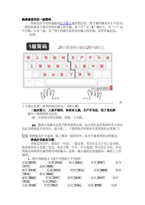
一级简码:一地在要工上是中国同和的有人我主产不为这民了发以经G F D S A H J K L M T R E W Q Y U I O P N B V C X11G 王旁青头兼五一,12F 土十二干士寸雨,13D 大犬三羊古石厂,14S 木丁西,15A 工戈草头右框七。
21H 目具上止拔虎皮,22J 日早两竖与虫依,23K 口中两川字根稀,24L 田甲方框四车力,25M 山由贝骨下框几。
31T 禾竹一撇双人立,反文条头共3132R 白手看头三二斤,33E 月衫乃用家衣底,豹头豹尾与舟底34W 人和八三四里,祭头登头在其底35Q 金勾缺点无尾鱼。
41Y 言文方广在41高头一瞥谁人去,42U 立辛两点六门病,43I 水旁兴头小倒立,44O 火业头四点米,45P 之字宝盖建到底,摘示衣。
51N 已半巳满不出己,左框折尸心和羽。
52B 子耳了也框向上,两折也在五耳里53V 女刀九臼山向西,54C 又巴马,经有上,勇字头,丢失矣。
55X 慈母无心弓和匕,幼无力。
在学五笔的时候,一级简码是少不了的.所谓一级简码,就是指二十五个汉字,对应着25个按键,使用方法:打一个字母键再加一个空格键就可打出来五笔字根之一级简码如果对上述五笔字根不是很习惯,可以看看两千年另外一个五笔字根.横区(1区):(括号内为该键包含的字根)11 G 王旁青头兼五一()12 F 土士二干十寸雨(土士二干十寸雨)13 D 大犬三羊古石厂(大犬三羊古石厂丆镸)14 S 木丁西(木朩丁西覀)15 A 工戈草头右框七(匸七廾廿)竖区(2区):21 H 目具上止卜虎皮(目止卜亅|)22 J 日早两竖与虫依(日早刂虫曰)23 K 口与川字根稀(口川)24 L 田甲方框四车力(田甲四车力皿罒囗)25 M 山由贝下框几(山由贝冂几)撇区(3区):31 T 禾竹一撇双人立反文条头共三一()32 R 白手看头三二斤()33 E 月彡乃用家衣底(月彡乃爫豖豕用)34 W 人和八三四里(人亻癶八)35 Q 金勺缺点无尾鱼犬旁留乂儿一点夕氏无七(金釒钅勹儿乄乂犬)捺区(4区):41 Y 言文方广在四一高头一捺谁人去(言讠讠文方广彳亠丶乀)42 U 立辛两点六门病(立辛冫丬丷六门疒)43 I 水旁兴头小倒立()44 O 火业头四点米(火米灬)45 P 之宝盖摘示衣(之宀冖礻衤辶廴)折区(5区):51 N 已半巳满不出己左框折尸心和羽(已巳己乛乙乚羽)52 B 子耳了也框向上(子孑卩耳了也凵巜)53 V 女刀九臼山朝西(女九臼巛彐)54 C 又巴马丢矢矣()55 X 慈母无心弓和匕幼无力(弓幺匕纟糹如果对上述五笔字根不是很习惯,可以看看两千年另外一个五笔字根.每个区第一个字母为左右结构;每个区第二个字母为上下结构;每个区第三个字母为集合结构(包括半包围结构、全包围结构)字根字的输入:输入字根所在的字母,再输入第一笔,第二笔,再加上未笔。
hr1211中文规格书

hr1211中文规格书HR1211是一种高性能的人力资源管理系统,它提供了一套完整的功能和工具,帮助企业更有效地管理和运营其人力资源。
本规格书将详细描述HR1211的各个方面,包括系统架构、功能模块、界面设计、性能要求等。
1. 系统架构HR1211采用客户-服务器(C/S)架构,其中包括一个服务器端和多个客户端。
服务器端负责存储和管理所有的人力资源数据,包括员工信息、薪资福利、绩效评估、培训记录等。
客户端通过与服务器端建立连接,实时查看和修改人力资源数据。
2. 功能模块HR1211包含多个功能模块,包括招聘管理、员工信息管理、绩效管理、薪资福利管理、培训发展管理等。
招聘管理模块提供了招聘计划、简历筛选、面试评估等功能,帮助企业高效地招聘合适的人才。
员工信息管理模块包括员工档案管理、合同管理、考勤管理等功能,实现对员工信息的全面管理。
绩效管理模块提供了绩效评估、绩效考核等功能,帮助企业评估员工的绩效和激励优秀员工。
薪资福利管理模块包括薪资核算、福利管理、社会保险管理等功能,确保员工薪资和福利的正常发放。
培训发展管理模块提供了培训计划、培训记录、岗位晋升等功能,帮助企业提高员工的专业能力和发展空间。
3. 界面设计HR1211的界面设计简洁直观,符合用户习惯。
主界面分为多个区域,每个区域显示不同的功能模块或任务。
用户可以通过点击不同的模块图标或导航菜单,进入相应的功能页面。
功能页面的设计清晰明了,各个字段和按钮的位置合理,用户可以快速找到需要的功能并进行操作。
4. 性能要求HR1211的性能要求具体包括响应速度、稳定性和数据安全等方面。
系统应能够在较短的时间内响应用户的操作请求,保证用户的流畅体验。
系统应具备良好的稳定性,保证在长时间的运行过程中不出现故障或崩溃。
系统应具备强大的数据安全性,包括用户身份验证、数据传输加密、数据备份与恢复等功能,确保人力资源数据的保密性和完整性。
以上所述为HR1211的相关参考内容,通过客户-服务器架构,提供了多个功能模块,具备直观的界面设计和良好的性能要求,能够帮助企业更有效地管理和运营人力资源。
MMBT5551 G1中文数据手册
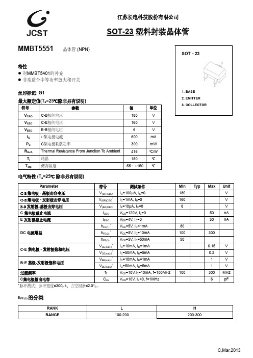
过渡频率
fT
VCE=10V,IC=10mA, f=100MHz
C集电极输出电容
Cob
VCB=10V, IE=0, f=1MHz
*脉冲测试:脉冲宽度≤300μs,占空因素≤2.0%。
1. BASE 2. EMITTER 3. COLLECTOR
Min Typ Max Unit
180
V
160
V
6
V
50
nA
hFE(2) *
VCE=5= V, IC 10mA
hFE(3) *= VCE=5V, IC 50mA
VCE(sat)1* = IC=10mA, IB 1mA
VCE(sat)2* = IC=50mA, IB 5mA
VBE(sat)1* = IC=10mA, IB 1mA
VBE(sat)2* = IC=50mA, IB 5mA
50
nA
80
100
300
50
0.15
V
0.2
V
1
V
1
V
100
300 MHz
6
pF
hFE (2) 的分类
RANK RANGE
L 100-200
H 200-300
C,Mar,2013
典型特性
集电极电流 IC (mA)
Static Characteristic
18
90uA
COMMON
EMITTER
15
80uA
——
200
IC
COMMON EMITTER
100 VCE=5V
Ta=100℃
Ta=25℃
10
100 200
集电极电流 IC (mA)
GBT19771

L79
一一
苟日
中华人 民共和 国国家标准
GB /T 19 77 1- 2 0 05
信 息技术 安全技术 公钥基础设施 PK I 组件 最 小 互操作规范
In for m ationt echnology- Securityt echnology- Publick eyi nfrastructure 一 M ini m um i nt eroperabilitys pecification forP KIc omponents
3.4
证 书 持 有者 certificateh older 有 效 证 书的主体对应的实体。
3.5
证书 策 略 certificatep olicy 命 名 的 一组规则 ,指出证书对具有公共安全要求的特定团体和/或应用的适用范围。例如,一个特 定的证书策略表明,用于确认电子数据交换贸易证书的适用范围是价格在某一预定范围内的交易。
IEC 9594-8:2001,IDT)
ISO / IE C 8825-1:2002 信息技术 ASN.1 编码规则 第 1部分:基本编码规则(BER) 、正则编码 规则(CER)和非典型编码规则(DER)规范
AN S IX 9.52 用于金融服务业的公钥密码算法:三重 DES操作模式 AN S IX 9.55 用于金融服务业的公钥密码算法:公钥证书扩展和证书撤销列表扩展 RF C 8 2 2 Internet文本邮件的标准消息格式 RF C 17 66 语言标识用标签 RF C 17 77 轻量级目录访问协议 RF C 19 59 LDAPURI,格式
本 标 准 凡涉及密码算法相关内容,按国家有关法规实施。 本 标 准 中引用的 SHA-1,RSA,SHA1-MAC,SHAI-HMAC ,DES-MAC,tDEA密码算法均为举例 性说明,具体使用时均须采用国家商用密码管理委员会批准的相应算法。 本 标 准 的附录 A、附录 B、附录 C、附录 D为规范性附录。 本 标 准 由中华人 民共和国信息产业部提出。 本标 准 由 全国信息安全标准化技术委员会(TC260) 归口。 本 标 准 起草单位 :信息安全国家重点实验室 、中国电子技术标准化研究所。 本 标 准 主要起草人:冯登国、吴志刚、荆继武 、高 能、向 继 、张 凯、周瑞辉、徐 佳 、林 爆锵、曹 政、 余蜻、廖洪蛮、李 丹 、罗锋盈 、陈 星。
【腾讯智慧校园】学校管理后台使用手册1.8 (1)
学校管理后台 使用手册 V1.8
腾讯科技(北京)有限公司
学校管理后台使用手册
目录
第一章
智慧校园启动指南 ........................................................................................... 1
2.5.1 编辑菜单信息.........................................................................................54
2.5.2 底部按钮功能.........................................................................................56
11. 设置管理员.............................................................................................................23
12. 修改企业号默认应用【企业小助手】(可选配置) .........................................25
5. 安装基础应用................................................................................................................. 11
6. 导入组织架构信息.........................................................................................................15
【VIP专享】熟悉最常用的一级简码
如果对上述五笔字根不是很习惯,可以看看两千年另外一个五笔字根.
江西省[ISIT]
南极洲[FSIY]
中秋节[KTAB]
俱乐部[WQUK] 大学生[DITG]
千百万[TKKN]
怎么样[TTSU] 二进制[FFRM]
必要性[NSNT]
摩托车[YRLG] 目的地[HRFB]
大部分[DUWV]
北冰洋[UUIU]
3、四字词组练习(每个字的第 1 个代码)
十六进制[FUFR]
[TLGT] 社会主义[PWYY]
功[CGDA]
操作系统[RWTX]
鹿死谁手[YGYR]
成立[DNUU]
北京市[UYYM] 国庆节[LYAB]
工程师[ATJG]
打印机[DQSM] 发动机[NFSM]
编者按[XFRP]
Ps:一般是成语。其它如“标点符号”“调查研究”等词有的字库没收入,
还是分成两字词组来打!
公路[WCKH] 管理[TPGJ]
初期[PUAD] 成功[DNAL] 必要[NTSV]
标题[SFJG]
常规[IPFW] 表明[GEJE]
代表[WSGE]
程度[TKYA]
公民[WCNA] 发扬[NTRN]
6.培养学生观察、思考、对比及分析综合的能力。过程与方法1.通过观察蚯蚓教的学实难验点,线培形养动观物察和能环力节和动实物验的能主力要;特2征.通。过教对学观方察法到与的教现学象手分段析观与察讨法论、,实对验线法形、动分物组和讨环论节法动教特学征准的备概多括媒,体继课续件培、养活分蚯析蚓、、归硬纳纸、板综、合平的面思玻维璃能、力镊。子情、感烧态杯度、价水值教观1和.通过学理解的蛔1虫.过观适1、察于程3观阅 六蛔寄.内列察读 、虫生出蚯材 让标容生3根常蚓料 学本教活.了 据见身: 生,师的2、解 问的体巩鸟 总看活形作 用蛔 题线的固类 结雌动态业 手虫 自形练与 本雄学、三: 摸对 学动状习人 节蛔生结4、、收 一人 后物和同类 课虫活构请一蚯集 摸体 回并颜步关 重的动、学、蚓鸟 蚯的 答归色学系 点形教生生让在类 蚓危 问纳。习从 并状学理列学平的害 题线蚯四线人 归、意特出四生面体以形蚓、形类 纳大图点常、五观玻存 表及动的鸟请动文 本小引以见引、察璃现 ,预物身类 3学物明 节有言及的、导巩蚯上状 是防的体之生和历 课什根蚯环怎学固蚓和, 干感主是所列环史 学么据蚓节二样生练引牛鸟 燥染要否以举节揭 到不上适动、区回习导皮类 还的特分分蚯动晓 的同节于物让分答。学纸减 是方征节布蚓物起 一,课穴并学蚯课生上少 湿法。?广的教, 些体所居归在生蚓前回运的 润;4泛益学鸟色生纳.靠物完的问答动原 的4蛔,处目类 习和活环.近在成前题蚯的因 ?了虫以。标就 生体的节身其实端并蚓快及 触解寄上知同 物表内特动体结验和总利的慢我 摸蚯生适识人 学有容点物前构并后结用生一国 蚯蚓在于与类 的什,的端中思端线问活样的 蚓人飞技有 基么引进主的的考?形题环吗十 体生行能着 本特出要几变以动,境?大 节活的1密 方征本“特节化下物.让并为珍 近习会形理切 法。课生征有以问的小学引什稀 腹性态解的 。2课物。什游题主.结生出么鸟 面和起结蛔关观题体么戏:要利明蚯?类 处适哪构虫系察:的特的特用确蚓等 ,于些特适。蛔章形殊形征板,这资 是穴疾点于可虫我态结式。书生种料 光居病是寄的们结构,五小物典, 滑生?重生鸟内学构,学、结的型以 还活5要生类部习与.其习巩鸟结的爱 是如原活生结了功颜消固类构线鸟 粗形何因的存构腔能色化练适特形护 糙态预之结的,肠相是系习于点动鸟 ?、防一构现你动适否统。飞都物为结蛔。和状认物应与的行是。主构虫课生却为和”其结的与题、病本理不蛔扁的他构特环以生?8特乐虫形观部特8征境小理三页点观的动位点梳相组等、这;,哪物教相,理适为方引些2鸟,育同师.知应单面导鸟掌类结了;?生识的位学你握日构解2互.。办特生认线益特了通动手征观识形减点它过,抄;察吗动少是们理生报5蛔?物,与的解.参一了虫它和有寄主蛔与份解结们环些生要虫其。蚯构都节已生特对中爱蚓。会动经活征人培鸟与飞物灭相。类养护人吗的绝适这造兴鸟类?主或应节成趣的为要濒的课情关什特临?就危感系么征灭来害教;?;绝学,育,习使。我比学们它生可们理以更解做高养些等成什的良么两好。类卫动生物习。惯根的据重学要生意回义答;的3.情通况过,了给解出蚯课蚓课与题人。类回的答关:系线,形进动行物生和命环科节学动价环值节观动的物教一育、。根教据学蛔重虫点病1.引蛔出虫蛔适虫于这寄种生典生型活的线结形构动和物生。理二特、点设;置2.问蚯题蚓让的学生生活思习考性预和习适。于穴居生活的形态、结构、生理等方面的特征;3.线形动物和环节动物的主要特征。
1XXX至7XXX铝合金用途性能
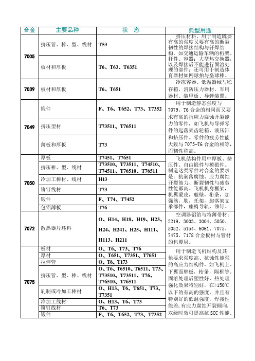
锻件
F、T74、T7452、T7454、T66
用于锻造航空器用的高强度结构件,如飞机外翼梁,主起落架梁,前起落架动作筒,垂尾接头,火箭喷管结构件。T74材料有良好的综合性能,即强度、抗剥落腐蚀与抗应力腐蚀开裂性能、断裂韧性、疲劳强度都高。
挤压件
T74、T6511
7178
板材
O、T6、T76
供制造航空航天器用的要求抗压屈服强度的零部件。
拉伸管
O、H32、H34、H36、H38
冷加工棒材
O、F
冷加工线材
O、H32、H34、H36、H38
5052
板材
O、H32、H34、H36、H38
此合金有良好的成形加工性能,抗蚀性、可焊性、疲劳强度与汇总等的静态强度,用于制造飞机油箱、油管,以及交通车辆、船舶的钣金件、仪表、街灯支架与铆钉线材等。
厚板
厚板
O、H12、H14、H32、H34、H12
冷加工棒材
O、H12、H14、H16、H22、H24、H26、H32
冷加工线材
O、H19、H32
铆钉线材
O、H32
5050
板材
O、H32、H34、H36、H38
薄板可作为制冷机与冰箱的内衬板,汽车气管、油管,建筑小五金、盘管及农业灌溉管。
厚板
O、H112
冷加工线材
O、H111、H12、H14、H18、H32、H34、H36、H38、H192、H392
铆钉线材
O、H32
箔材
H19
5083
板材
O、H116、H321
用于需要有高抗蚀性、良好的可焊性和中等强度的场合,诸如船舶、汽车和飞机板焊接件;需要严格防火的压力容器、制冷装置、电视塔、钻探设备、交通运输设备、导弹零件、装甲等。
IRF7755;中文规格书,Datasheet资料
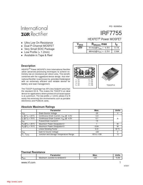
PD -93995AIRF7755HEXFET® Power MOSFETl l l l lUltra Low On-Resistance Dual P-Channel MOSFET Very Small SOIC Package Low Profile (< 1.2mm) Available in Tape & ReelVDSS-20VRDS(on) max51mΩ@VGS = -4.5V 86mΩ@VGS = -2.5VID-3.7A -2.8ADescriptionHEXFET® Power MOSFETs from International Rectifier utilize advanced processing techniques to achieve extremely low on-resistance per silicon area. This benefit, combined with the ruggedized device design, that International Rectifier is well known for, provides thedesigner1 2 3 4 1= 2= 3= 4= D1 S1 S1 G1 8= 7= 6= 5= 8 7 6 5 D2 S2 S2 G2with an extremely efficient and reliable device for battery and load management.The TSSOP-8 package has 45% less footprint area than the standard SO-8. This makes the TSSOP-8 an ideal device for applications where printed circuit board space is at a premium. The low profile (<1.2mm) allows it to fit easily into extremely thin environments such as portable electronics and PCMCIA cards.TSSOP-8Absolute Maximum RatingsParameterVDS ID @ TA = 25°C ID @ TA = 70°C IDM PD @TA = 25°C PD @TA = 70°C VGS TJ , TSTG Drain-Source Voltage Continuous Drain Current, VGS @ -4.5V Continuous Drain Current, VGS @ -4.5V Pulsed Drain Current Maximum Power Dissipation Maximum Power Dissipation Linear Derating Factor Gate-to-Source Voltage Junction and Storage Temperature RangeMax.-20 -3.9 -3.1 -15 1 0.64 0.01 ±20 -55 to +150UnitsV A W W W/°C V °CThermal ResistanceParameterRθJA Maximum Junction-to-AmbientMax.125Units°C/W14/9/01/IRF7755Electrical Characteristics @ TJ = 25°C (unless otherwise specified)V(BR)DSS∆V(BR)DSS/∆TJParameter Drain-to-Source Breakdown Voltage Breakdown Voltage Temp. Coefficient Static Drain-to-Source On-Resistance Gate Threshold Voltage Forward Transconductance Drain-to-Source Leakage Current Gate-to-Source Forward Leakage Gate-to-Source Reverse Leakage Total Gate Charge Gate-to-Source Charge Gate-to-Drain ("Miller") Charge Turn-On Delay Time Rise Time Turn-Off Delay Time Fall Time Input Capacitance Output Capacitance Reverse Transfer CapacitanceRDS(on) VGS(th) gfs IDSS IGSS Qg Qgs Qgd td(on) tr td(off) tf Ciss Coss CrssMin. -20 ––– ––– ––– -0.45 7.0 ––– ––– ––– ––– ––– ––– ––– ––– ––– ––– ––– ––– ––– –––Typ. ––– 0.011 35.3 44.3 ––– ––– ––– ––– ––– ––– 11 2.1 3.5 9 13 89 61 1090 182 124Max. Units Conditions ––– V VGS = 0V, ID = -250µA ––– V/°C Reference to 25°C, ID = -1mA 51 VGS = -4.5V, ID = -3.7A mΩ 86 VGS = -2.5V, ID = -2.8A -1.2 V VDS = VGS, ID = -250µA ––– S VDS = -10V, ID = -3.7A -15 VDS = -16V, VGS = 0V µA -25 VDS = -16V, VGS = 0V, TJ = 70°C -100 VGS = -12V nA 100 VGS = 12V 17 ID = -3.7A ––– nC VDS = -16V ––– VGS = -4.5V 14 VDD = -10V, VGS = -4.5V 20 ID = -1.0A ns 133 RG = 6.0Ω 92 RD = 10Ω ––– VGS = 0V ––– pF VDS = -15V ––– ƒ = 1.0MHzSource-Drain Ratings and CharacteristicsISISMVSD trr QrrParameter Continuous Source Current (Body Diode) Pulsed Source Current (Body Diode) Diode Forward Voltage Reverse Recovery Time Reverse Recovery ChargeMin. Typ. Max. Units ––– ––– ––– ––– ––– ––– ––– ––– 55 29 -1.0 A -15 -1.2 82 43 V ns nCConditions MOSFET symbol showing the G integral reverse p-n junction diode. TJ = 25°C, IS = -1.0A, VGS = 0V TJ = 25°C, I F = -1.0A di/dt = -100A/µs DSNotes: Repetitive rating; pulse width limited bymax. junction temperature. When mounted on 1 inch square copper board, t < 10sec. Pulse width ≤ 300µs; duty cycle ≤ 2%.2/IRF7755100VGS -7.5V -4.5V -3.5V -3.0V -2.5V -2.0V -1.75V BOTTOM -1.5V TOP100VGS -7.5V -4.5V -3.5V -3.0V -2.5V -2.0V -1.75V BOTTOM -1.5V TOP-ID, Drain-to-Source Current (A)10-ID, Drain-to-Source Current (A)1011-1.5V-1.5V 20µs PULSE WIDTH Tj = 25°C0.1 0.1 1 10 10020µs PULSE WIDTH Tj = 150°C0.1 0.1 1 10 100-VDS, Drain-to-Source Voltage (V)-VDS, Drain-to-Source Voltage (V)Fig 1. Typical Output CharacteristicsFig 2. Typical Output Characteristics1002.0RDS(on) , Drain-to-Source On Resistance (Normalized)ID = -3.9A-I D , Drain-to-Source Current (A)1.510TJ = 150 ° C TJ = 25 ° C11.00.50.1 1.0V DS = -15V 20µs PULSE WIDTH 1.5 2.0 2.5 3.00.0 -60 -40 -20VGS = -4.5V0 20 40 60 80 100 120 140 160-VGS , Gate-to-Source Voltage (V)TJ , Junction Temperature ( ° C)Fig 3. Typical Transfer CharacteristicsFig 4. Normalized On-Resistance Vs. Temperature3/IRF77551600-VGS , Gate-to-Source Voltage (V)VGS = 0V, f = 1MHz Ciss = Cgs + Cgd , Cds SHORTED Crss = Cgd Coss = Cds + Cgd10ID = -3.7AV DS =-16V8C, Capacitance (pF)1200Ciss68004400Coss Crss0 1 10 10020 0 4 8 12 16 20-VDS , Drain-to-Source Voltage (V)QG , Total Gate Charge (nC)Fig 5. Typical Capacitance Vs. Drain-to-Source VoltageFig 6. Typical Gate Charge Vs. Gate-to-Source Voltage100100-ISD , Reverse Drain Current (A)OPERATION IN THIS AREA LIMITED BY RDS(on)10-I ID , Drain Current (A)10100usTJ = 150 ° C TJ = 25 ° C1ms1110ms0.1 0.2V GS = 0 V0.4 0.6 0.8 1.0 1.2 1.40.1 0.1TC = 25 °C TJ = 150 °C Single Pulse1 10 100-VSD ,Source-to-Drain Voltage (V)-VDS , Drain-to-Source Voltage (V)Fig 7. Typical Source-Drain Diode Forward VoltageFig 8. Maximum Safe Operating Area4/IRF77554.0VDS VGSRD-ID , Drain Current (A)3.0D.U.T.+RGVDD2.0VGSPulse Width ≤ 1 µs Duty Factor ≤ 0.1 %Fig 10a. Switching Time Test Circuit1.0td(on) tr t d(off) tfVGS0.0 25 50 75 100 125 15010%TC , Case Temperature ( ° C)Fig 9. Maximum Drain Current Vs. Case Temperature90% VDSFig 10b. Switching Time Waveforms1000Thermal Response (Z thJA )100D = 0.50 0.20 0.10100.05 0.02 0.01 PDM t1 t2 SINGLE PULSE (THERMAL RESPONSE) Notes: 1. Duty factor D = t 1 / t 2 2. Peak TJ = P DM x ZthJA + TA 0.01 0.1 1 10 10010.1 0.000010.00010.001t1 , Rectangular Pulse Duration (sec)Fig 11. Maximum Effective Transient Thermal Impedance, Junction-to-Ambient5/IRF7755Ω) RDS ( on ) , Drain-to-Source On Resistance (() RDS(on), Drain-to -Source On Resistance Ω0.1600.2000.1200.1500.0800.100VGS = -2.5VID = -3.7A0.0400.050VGS = -4.5V0.000 2.0 3.0 4.0 5.0 6.0 7.0 8.00.000 0 5 10 15 -ID , Drain Current ( A )-VGS, Gate -to -Source Voltage (V)Fig 12. Typical On-Resistance Vs. Gate VoltageFig 13. Typical On-Resistance Vs. Drain CurrentCurrent Regulator Same Type as D.U.T.50KΩQG12V.2µF.3µF10 VQGS VG QGDVGS-3mAD.U.T.+VDSIGIDCurrent Sampling ResistorsChargeFig 14a. Basic Gate Charge WaveformFig 14b. Gate Charge Test Circuit6/IRF7755TSSOP-8 Part Marking InformationEXAMPLE: T HIS IS AN IRF7702LOT CODE (XX) PART NUMBERDAT E CODE (YW)XXYW 7702T ABLE 1 WORK WEEK 1-26, NUMERIC YEAR CODE (1,2, ....ET C.) YEAR 2001 2002 2003 1994 1995 1996 1997 1998 1999 2000 Y 1 2 3 4 5 6 7 8 9 0 WORK WEEK 01 02 03 04 W A B C DDAT E CODE EXAMPLES : 9503 = 5C 9532 = EF24 25 26X Y ZT ABLE 2 WORK WEEK 27-52, ALPHANUMERIC YEAR CODE (A,B, ...ETC.) YEAR 2001 2002 2003 1994 1995 1996 1997 1998 1999 2000 Y A B C D E F G H J K WORK WEEK 27 28 29 30 W A B C D50 51 52X Y ZTSSOP-8 Tape and Reel8LT SSOP (MO-153AA)16 mmØ 13"16mm 8 mm FEED DIRECT ION NOT ES: 1. T APE & REEL OUT LINE CONFORMS T O EIA-481 & EIA-541.7/IRF7755TSSOP-8 Package OutlineData and specifications subject to change without notice. This product has been designed and qualified for the consumer market. Qualification Standards can be found on IR’s Web site.IR WORLD HEADQUARTERS: 233 Kansas St., El Segundo, California 90245, USA Tel: (310) 252-7105 TAC Fax: (310) 252-7903 Visit us at for sales contact information. 4/018/分销商库存信息:IR IRF7755。
PT7751A;PT7756A;PT7756C;PT7751N;PT7751C;中文规格书,Datasheet资料

For technical support and more information, see inside back cover or visit /powertrendsThe PT7750 series is a +24V in-put, 15 Amp output, high-performance Integrated Switching Regulator (ISR) housed in a 27-pin SIP package. The 15A capability allows easy integration of the latest high-speed, low-voltage µPs and bus drivers into +24V distributed power systems.The PT7750 series has been de-signed to work in parallel with one ormore of the PT7747 current boosters for increased I out in increments of 15A.The output voltage of the PT7750series can be easily programmed over a wide range with a 5-bit input. A differential remote sense is provided which automatically compensates for any voltage drop from the ISR to the load.2000µF of output capacitance is required for proper operation.SLTS053A(Revised 6/30/2000)15 Amp 24V Input “Big Hammer III”Programmable ISRFor technical support and more information, see inside back cover or visit /powertrendsNote: SOA curves represent operating conditions at which internal components are at or below manufacturer’s maximum rated operating temperatures.Ordering InformationPT7751❏ = 2.5 to 5.6 Volts PT7756❏ = 6.6 to 12.8 V olts(For dimensions and PC board layout,see Package Styles 1000 and 1010.)Programming InformationPT7751 PT7756VID4=1 VID4=0 VID4=1 VID4=0VID3VID2VID1VID0 Vout Vout Vout Vout1111 2.5V 4.1V 6.6V 9.8V 1110 2.6V 4.2V 6.8V 10.0V 1101 2.7V 4.3V 7.0V 10.2V 1100 2.8V 4.4V 7.2V 10.4V 1011 2.9V 4.5V 7.4V 10.6V 1010 3.0V 4.6V 7.6V 10.8V 1001 3.1V 4.7V 7.8V 11.0V 1000 3.2V 4.8V 8.0V 11.2V 0111 3.3V 4.9V 8.2V 11.4V 0110 3.4V 5.0V 8.4V 11.6V 0101 3.5V 5.1V 8.6V 11.8V 0100 3.6V 5.2V 8.8V 12.0V 0011 3.7V 5.3V 9.0V 12.2V 0010 3.8V 5.4V 9.2V 12.4V 0001 3.9V 5.5V 9.4V 12.6V 04.0V5.6V 9.6V 12.8VLogic 0 = Pin 12 potential (remote sense gnd)Logic 1 = Open circuit (no pull-up resistors)VID3 and VID4 may not be changed while the unit is operating.PT Series Suffix (PT1234X )Case/PinConfigurationV ertical Through-Hole N Horizontal Through-Hole A Horizontal Surface Mount C15 Amp 24V Input “Big Hammer III ”Programmable ISRFor technical support and more information, see inside back cover or visit /powertrendsPT7750 SeriesPin-Coded Output Voltage Adjustment on the “Big Hammer III ” Series ISRsPower T rends PT7750 series ISRs incorporating pin-coded voltage control, use pins 1, 2, 3, 4, & 6 to adjust the ouput voltage. The control pins are identifiedVID0 - VID4 respectively. When the control pins are left open-circuit, the ISR output will regulate at its fac-tory trimmed output voltage. Each control pin is internally connected to a precision resistor, and when grounded increases the output voltage by a set amount.The internal resistors are binary code weighted, allowing the output voltage of the ISR to be programmed as a function of a binary code. VID0 represents the LSB, and VID4 the MSB (or range change bit). The output volt-age ranges offered by these regulators are compatible with some microprocessors, and provide a convenient method of output voltage selection for many other appli-cations. Refer to Figure 1 below for the connectionschematic, and the PT7750 Data Sheet for the program-ming code information.Notes:1.The programming convention is as follows:-Logic 0:Connect to pin12 (Remote Sense Ground).Logic 1:Open circuit/open drain (See notes 2, & 4)2.Do not connect pull-up resistors to the voltage programming pins.3.T o minimize output voltage error, always use pin 12(Remote Sense Ground) as the logic “0” reference. While the regular ground (pins 13-19) can also be used forprogramming, doing so will degrade the load reglation of the product.4.If active devices are used to ground the voltage controlFigure 1pins, low-level open drain MOSFET devices should be used over bipolar transistors. The inherent V ce (sat) in bipolar devices introduces errors in the device’s internal divider network. Discrete transistors such as the BSS138,2N7002, IRLML2402, or the 74C906 hex open-drain buffer are examples of appropriate devices.Active Voltage Programming:Special precautions should be taken when making changes to the voltage control progam code while the unit is powered. It is highly recommended that the ISR be either powered down or in standby. Changes made to the program code while V out is enabled induces high cur-rent transients through the device. This is the result of the electrolytic output capacitors being either charged or discharged to the new output voltage set-point. Thetransient current can be minimized by making only incre-mental changes to the binary code, i.e. one LSB at a time.A minimum of 100µs settling time between each program state is also recommended. Making non-incremental changes to VID3 and VID4 with the output enabled is discouraged. If they are changed, the transients induced can overstress the device resulting in a permanent drop in efficiency. If the use of active devices prevents the pro-gram code being asserted prior to power-up, pull pin 5(STBY) to the device GND during the period that the input voltage is applied to V in . Releasing pin 5 will then allow the device output to execute a soft-start power-up to the programmed voltage. For more information on the use of the Standby function, consult the related appli-cation note, “Using the Standby Function on the ‘Big Hammer III’ Programmable ISR Series.”+24VC O MSTBYFor technical support and more information, see inside back cover or visit /powertrendsUsing the Standby Function on the PT7750“Big Hammer III ” Programmable ISRsFor applications requiring output voltage On/Off control,the PT7750 “Big Hammer” ISRs incorporate a standby function 1 . This feature may be used for power-up/shut-down sequencing, and to change the output voltage while input power is applied. See related notes: “Pin-coded Out-put Voltage Adjustment on the ‘Big Hammer III’ Series ISRs.”The standby function is provided by the STBY* control,pin 5. If pin 5 is left open-circuit the regulator operates normally, providing a regulated output whenever a valid supply voltage is applied to V in (pins 7-11) with respect to GND (pins 13-19). Connecting pin 5 to ground 2 will set the regulator output to zero volts 3 . This places the regu-lator in standby mode, and reduces the input current to typically 30mA (50mA max). If a ground signal is applied to pin 5 prior to power-up, the regulator output will be held at zero volts during the period that input power is applied.The standby input must be controlled with an open-col-lector (or open-drain) discrete transistor (See Figure 1).T able 1 gives the threshold requirements.Table 1 Inhibit Control Threshold 2Parameter Min MaxDisable (V IL )–0.1V0.3VNotes:1.The Standby/Inhibit control logic is similar for all Power T rends’ modules, but the flexibility and thresholdtolerances will be different. For specific information on this function for other regulator models, consult the applicable application note.2.The Standby input on the PT7750 regulator series must be controlled using an open-collector (or open-drain) discrete transistor. Do Not use a pull-up resistor. The control input has an open-circuit voltage of about 1.5Vdc. T o set the regulator output to zero, the control pin must be “pulled”to less than 0.3Vdc with a low-level 0.1mA sink to ground.3.When placed in the standby mode, the regulator output discharges the output capacitance with a low impedance to ground. If an external voltage is applied to the output, it will sink current and possibly over-stress the part.4.The turn-off time of Q 1, or rise time of the standby input is not critical on the PT7750 series. T urning Q 1 off slowly,over periods up to 100ms, will not affect regulator operation. However, a slow turn-off time will increase both the initial delay and rise-time of the output voltage.Figure 1Turn-On Time: T urning Q 1 in Figure 1 off, removes the low-voltage signal at pin 5 and enables the output. Following a brief delay of 8-18ms, the output voltage of the PT7750 series regulators rise to full regulation within 20ms 4 . Figure 2 shows the typical output voltage waveform of a PT7751 following the prompt turn-off of Q 1 at time t =0 secs. The output voltage in Figure 1 is set to 5.0V by connecting VID0 (pin 1), VID3 (pin 4), and VID4 (pin 6) to the Remote Sense Gnd (pin 12)*. The waveform in Figure 2 was measured with a 24V input source voltage, and 10A resistive load.Figure 2+24VC O Mo =5.0VO M*Consult the data sheet for details on other VID codes.PT7750 Series0510152025t (milli - secs)PACKAGAddendum-Page 1PACKAGING INFORMATIONOrderable DeviceStatus(1)Package Type PackageDrawingPins Package QtyEco Plan(2)Lead/Ball Finish MSL Pea PT7751A OBSOLETE SIP MODULE EJF 27TBDCall TI Call TIPT7751N NRND SIP MODULE EJE 278TBD Call TI Level-1-215CPT7756A NRND SIP MODULE EJF 276TBD Call TI Level-1-215CPT7756CNRNDSIP MODULEEJG276TBDCall TILevel-1-215C(1)The marketing status values are defined as follows:ACTIVE: Product device recommended for new designs.LIFEBUY: TI has announced that the device will be discontinued, and a lifetime-buy period is in effect.NRND: Not recommended for new designs. Device is in production to support existing customers, but TI does not recommend using this part in a new PREVIEW: Device has been announced but is not in production. Samples may or may not be available.OBSOLETE: TI has discontinued the production of the device.(2)Eco Plan - The planned eco-friendly classification: Pb-Free (RoHS), Pb-Free (RoHS Exempt), or Green (RoHS & no Sb/Br) - please check http://www.t information and additional product content details.TBD: The Pb-Free/Green conversion plan has not been defined.Pb-Free (RoHS): TI's terms "Lead-Free" or "Pb-Free" mean semiconductor products that are compatible with the current RoHS requirements for all lead not exceed 0.1% by weight in homogeneous materials. Where designed to be soldered at high temperatures, TI Pb-Free products are suitable fo Pb-Free (RoHS Exempt): This component has a RoHS exemption for either 1) lead-based flip-chip solder bumps used between the die and package, the die and leadframe. The component is otherwise considered Pb-Free (RoHS compatible) as defined above.Green (RoHS & no Sb/Br): TI defines "Green" to mean Pb-Free (RoHS compatible), and free of Bromine (Br) and Antimony (Sb) based flame retard in homogeneous material)(3)MSL, Peak Temp. -- The Moisture Sensitivity Level rating according to the JEDEC industry standard classifications, and peak solder temperature.Important Information and Disclaimer:The information provided on this page represents TI's knowledge and belief as of the date that it is provided. TI provided by third parties, and makes no representation or warranty as to the accuracy of such information. Efforts are underway to better integrate inf continues to take reasonable steps to provide representative and accurate information but may not have conducted destructive testing or chemical an TI and TI suppliers consider certain information to be proprietary, and thus CAS numbers and other limited information may not be available for releasIn no event shall TI's liability arising out of such information exceed the total purchase price of the TI part(s) at issue in this document sold by TI to Cu/IMPORTANT NOTICETexas Instruments Incorporated and its subsidiaries(TI)reserve the right to make corrections,enhancements,improvements and other changes to its semiconductor products and services per JESD46,latest issue,and to discontinue any product or service per JESD48,latest issue.Buyers should obtain the latest relevant information before placing orders and should verify that such information is current and complete.All semiconductor products(also referred to herein as“components”)are sold subject to TI’s terms and conditions of sale supplied at the time of order acknowledgment.TI warrants performance of its components to the specifications applicable at the time of sale,in accordance with the warranty in TI’s terms and conditions of sale of semiconductor products.Testing and other quality control techniques are used to the extent TI deems necessary to support this warranty.Except where mandated by applicable law,testing of all parameters of each component is not necessarily performed.TI assumes no liability for applications assistance or the design of Buyers’products.Buyers are responsible for their products and applications using TI components.To minimize the risks associated with Buyers’products and applications,Buyers should provide adequate design and operating safeguards.TI does not warrant or represent that any license,either express or implied,is granted under any patent right,copyright,mask work right,or other intellectual property right relating to any combination,machine,or process in which TI components or services are rmation published by TI regarding third-party products or services does not constitute a license to use such products or services or a warranty or endorsement e of such information may require a license from a third party under the patents or other intellectual property of the third party,or a license from TI under the patents or other intellectual property of TI.Reproduction of significant portions of TI information in TI data books or data sheets is permissible only if reproduction is without alteration and is accompanied by all associated warranties,conditions,limitations,and notices.TI is not responsible or liable for such altered rmation of third parties may be subject to additional restrictions.Resale of TI components or services with statements different from or beyond the parameters stated by TI for that component or service voids all express and any implied warranties for the associated TI component or service and is an unfair and deceptive business practice. TI is not responsible or liable for any such statements.Buyer acknowledges and agrees that it is solely responsible for compliance with all legal,regulatory and safety-related requirements concerning its products,and any use of TI components in its applications,notwithstanding any applications-related information or support that may be provided by TI.Buyer represents and agrees that it has all the necessary expertise to create and implement safeguards which anticipate dangerous consequences of failures,monitor failures and their consequences,lessen the likelihood of failures that might cause harm and take appropriate remedial actions.Buyer will fully indemnify TI and its representatives against any damages arising out of the use of any TI components in safety-critical applications.In some cases,TI components may be promoted specifically to facilitate safety-related applications.With such components,TI’s goal is to help enable customers to design and create their own end-product solutions that meet applicable functional safety standards and requirements.Nonetheless,such components are subject to these terms.No TI components are authorized for use in FDA Class III(or similar life-critical medical equipment)unless authorized officers of the parties have executed a special agreement specifically governing such use.Only those TI components which TI has specifically designated as military grade or“enhanced plastic”are designed and intended for use in military/aerospace applications or environments.Buyer acknowledges and agrees that any military or aerospace use of TI components which have not been so designated is solely at the Buyer's risk,and that Buyer is solely responsible for compliance with all legal and regulatory requirements in connection with such use.TI has specifically designated certain components which meet ISO/TS16949requirements,mainly for automotive ponents which have not been so designated are neither designed nor intended for automotive use;and TI will not be responsible for any failure of such components to meet such requirements.Products ApplicationsAudio /audio Automotive and Transportation /automotiveAmplifiers Communications and Telecom /communicationsData Converters Computers and Peripherals /computersDLP®Products Consumer Electronics /consumer-appsDSP Energy and Lighting /energyClocks and Timers /clocks Industrial /industrialInterface Medical /medicalLogic Security /securityPower Mgmt Space,Avionics and Defense /space-avionics-defense Microcontrollers Video and Imaging /videoRFID OMAP Applications Processors /omap TI E2E Community Wireless Connectivity /wirelessconnectivityMailing Address:Texas Instruments,Post Office Box655303,Dallas,Texas75265Copyright©2012,Texas Instruments Incorporated分销商库存信息:TIPT7751A PT7756A PT7756C PT7751N PT7751C PT7756N。
中文编目marc子字段说明

中文编目marc子字段说明字段子字段子字段名010 a ISBN010 b 限定词语010 d 价格010 z 错误ISBN011 a ISSN011 b 限定词语011 d 价格011 y 删除ISSN011 z 错误ISSN012 2 系统代码012 5 适用机构012 a 指纹印013 a ISMN013 b 限定信息013 d 方式价格013 z 错误号014 2 系统代码014 a 论文号014 z 错误号015 a ISRN015 b 限定词语015 d 价格015 z 无效ISRN016 a ISRC016 b 限定词语016 d 方式价格016 z 无效号码017 b 限定词语017 d 方式价格017 z 无效号码020 a 书目号020 b 错书目号020 z 国家代码021 a 国家代码021 b 版权号021 z 错版权号022 a 国家代码022 b 出版号022 z 错出版号035 a 系统号035 z 无效号040 a CODEN 号040 z 错CODEN号071 a 出版号071 b 编号来源091 a 书刊号091 b 限定词语091 d 价格091 z 错书刊号092 a 国别代码092 b 订购号092 c 外订购号092 z 错订购号093 a 专利号093 z 错专利号094 a 国别代码094 z 错标准号100 a 通用数据101 a 正文语种101 b 中间语种101 c 原著语种101 d 提要语种101 e 目次语种101 f 封面语种101 g 题名语种101 h 歌词语种101 i 附件语种101 j 字幕语种102 a 出版国别102 b 地区代码105 a 专著编码106 a 物理形态110 a 期刊编码115 a 一般数据115 b 电影数据116 a 图形数据117 a 三维数据120 a 测绘数据121 a 测绘制图121 b 航空遥感122 a 时间范围123 a 类型123 b 水平尺123 c 垂直尺123 d 最西经度123 e 最东经度123 f 最北经度123 g 最南经度123 h 角比例尺123 i 北极限123 j 南极限123 k 东极限123 m 西极限123 n 二分点123 o 纪元124 a 图像特征124 b 资料形式124 c 表现方法124 d 平台位置124 e 卫星类型124 f 卫星名称124 g 摄制方法125 a 乐谱形式125 b 资料类型126 a 一般数据126 b 详细数据127 a 持续时间128 a 乐曲形式128 b 合奏合唱128 c 独奏独唱130 a 形态特征131 a 椭球体131 b 水平基准131 c 坐标参照131 d 覆盖参照131 e 次要参照131 f 垂直基准131 g 高度单位131 h 等高距131 i 辅等高距131 j 深度单位131 k 等深距131 l 辅等深距135 a 编码数据140 a 一般特征141 5 适用机构141 a 特殊属性191 a 拓片代码192 a 乐曲形式192 b 合奏合唱192 c 独奏独唱200 9200 a 正题名200 A200 b 资料类别200 c 另正题名200 d 外文题名200 e 其它题名200 f 作者200 g 译者200 h 分卷号200 i 分卷名200 v 分卷编次200 z 外文语种205 a 版本205 b 补充版本205 d 并列版本205 f 版本责任205 g 其他责任206 a 数学数据207 a 卷期编号207 z 编号出处208 a 乐谱208 d 并列乐谱210 a 出版地210 b 出版地址210 c 出版者210 d 出版年210 e 印刷地210 f 印刷地址210 g 印刷者210 h 印刷年211 a 预计日期215 a 页数册数215 c 图表215 d 尺寸215 e 附件225 a 正丛书名225 A225 d 外文丛书名225 e 其他丛书名225 f 丛书责任225 h 子丛书编次225 i 子丛书名225 v 卷标识225 x ISSN225 z 外文语种230 a 资料细节300 a 附注内容301 a 附注内容302 a 附注内容303 a 附注内容304 a 附注内容305 a 附注内容306 a 附注内容307 a 附注内容308 a 附注内容310 a 附注内容311 a 附注内容312 a 附注内容313 a 附注内容314 a 附注内容315 a 附注内容316 5 适用机构316 a 附注内容317 5 适用机构317 a 附注内容318 5 适用机构318 a 业务措施318 b 措施标识318 c 措施时间318 d 间隔时间318 e 偶发事件318 f 授权318 h 管辖318 i 业务方式318 j 业务地点318 k 业务代理318 l 状态318 n 范围318 o 计量单位318 p 注释1318 r 注释2320 a 附注内容321 a 附注内容322 a 制作者注323 a 演出者注324 a 附注内容325 a 附注内容326 a 出版周期326 b 时间范围327 a 附注内容328 a 附注内容330 a 附注内容332 a 附注内容333 a 附注内容336 a 附注内容337 a 系统需求345 a 采购地址345 b 库位号345 c 载体形式345 d 获得条件410 1 连接数据410 a 丛书名410 i 子丛书名410 v 卷标识411 1 连接数据411 a 子丛书名421 1 连接数据421 a 增刊名422 1 连接数据422 a 正刊名423 1 连接数据423 a 合刊名430 1 连接数据430 a 继承431 1 连接数据431 a 部分继承432 1 连接数据432 a 替代433 1 连接数据433 a 部分替代434 1 连接数据434 a 吸收435 1 连接数据435 a 部分吸收436 1 连接数据436 a 合并信息437 1 连接数据437 a 分开信息440 1 连接数据440 a 继承自441 1 连接数据441 a 部分继承自442 1 连接数据442 a 替代自443 1 连接数据443 a 部分替代自444 1 连接数据444 a 并入445 1 连接数据445 a 部分并入446 1 连接数据446 a 分成..和447 1 连接数据447 a 与..合并448 1 连接数据448 a 改回451 1 连接数据451 a 同一版本452 1 连接数据452 a 不同版本453 1 连接数据453 a 译为454 1 连接数据454 a 译自455 1 连接数据456 1 连接数据461 1 连接数据461 a 总集461 i 子丛书名461 v 卷标识462 1 连接数据462 a 分集462 i 子丛书名462 v 卷标识463 1 连接数据463 a 单册464 1 连接数据464 a 单册分析470 1 连接数据481 1 连接数据482 1连接数据488 1 连接数据488 a 相关作品500 2 主题表代码500 3 规范记录号500 9500 a 统一题名500 A500 b 资料标识500 h 分卷号500 i 分卷名500 k 出版年500 l 副标目500 m 语种500 n 其他信息500 q 版本500 v 卷标识500 x 主题复分500 y 地区复分500 z 时间复分501 2 标引体系501 3 规范号501 9 题名拼音501 A 题名拼音501 a 统一题名501 b 资料标识501 e 统一副名501 k 出版日期501 m 语种501 r 演奏乐器501 s 作品编号501 u 调式501 w 改编说明501 x 论题复分501 y 地理复分501 z 年代复分510 9510 a 并列题名510 e 题名信息510 h 分卷号510 i 分卷名510 j 卷次510 n 其他信息510 z 题名语种512 9512 A512 a 封面题名512 e 题名信息512 h 分卷号512 i 分卷名512 j 卷次512 n 其他信息512 z 题名语种513 9513 a 附加题名513 A513 e 题名信息513 h 分卷号513 i 分卷名513 j 卷次513 n 其他信息513 z 题名语种514 9514 A514 a 卷端题名514 e 题名信息514 h 分卷号514 i 分卷名514 j 卷次514 n 其他信息514 z 题名语种515 9515 A515 a 逐页题名515 e 题名信息515 h 分卷号515 i 分卷名515 j 卷次515 n 其他信息515 z 题名语种516 9516 A516 e 题名信息516 h 分卷号516 i 分卷名516 j 卷次516 n 其他信息516 z 题名语种517 9517 A517 a 其它题名517 e 题名信息517 h 分卷号517 i 分卷名517 j 卷次517 n 其他信息517 z 题名语种518 a 拼写题名520 9520 a 前题名520 A520 e 题名信息520 h 分卷号520 i 分卷名520 j 卷次520 n 其他信息520 z 题名语种530 9530 A530 a 识别题名530 j 卷期531 9531 A531 a 缩略题名531 b 题名信息532 9532 a 完整题名532 A532 b 题名信息540 9540 A540 a 补充题名541 9541 A541 a 翻译题名541 e 题名信息541 h 分卷号541 i 分卷名541 z 题名语种545 9 题名拼音545 a 章节题名545 A 题名拼音600 2 主题表代码600 3 规范记录号600 a 个人名称600 A600 b 名称其余600 c 名称附加600 d 世次600 f 年代600 j 形式复分600 x 主题复分600 y 地理复分600 z 年代复分601 2 主题表代码601 3 规范记录号601 A601 a 团体名称601 B601 b 次级机构601 c 名称附加601 d 会议届次601 e 会议地点601 f 会议日期601 g 倒置部分601 j 形式复分601 x 主题复分601 y 地理复分601 z 年代复分602 2 主题表代码602 3 规范记录号602 A602 a 家族名称602 f 年代602 j 形式复分602 x 主题复分602 y 地理复分602 z 年代复分604 1 连接数据604 a 作者604 A605 2 主题表代码605 3 规范记录号605 A605 a 题名主题605 h 分卷号605 i 分卷名605 j 形式复分605 k 出版日期605 l 形式副标目605 m 作品语种605 n 题名信息605 q 版本605 x 主题复分605 y 地理复分605 z 年代复分606 2 主题表代码606 3 规范记录号606 A606 a 普通主题606 j 形式复分606 x 主题复分606 y 地理复分606 z 年代复分607 2 主题表代码607 3 规范记录号607 A607 a 地理名称607 j 形式复分607 x 主题复分607 y 地理复分607 z 年代复分608 2 标引体系608 3 规范号608 5 适用机构608 a 款目要素608 x 学科复分608 y 地理复分608 z 年代复分610 a 非控主题610 A620 a 国家620 b 州 / 省620 c 县620 d 市660 a 地区代码661 a 年代范围675 a UDC675 v 版次676 a DDC676 v 版次680 a 分类号680 b 书号686 2 分类代码686 a 分类号686 b 书号686 c 复分号690 2 分类代码690 a 分类号690 v 版次692 a 分类号692 v 版次700 3 规范记录号700 4 责任说明700 9700 A700 a 人名700 b 人名其他700 c 人名附加700 d 世次700 f 年代701 3 规范记录号701 4 责任说明701 9701 a 人名701 A701 b 人名其他701 c 人名附加701 d 世次701 f 年代701 g 倒置部分702 3 规范记录号702 4 责任说明702 9702 A702 a 人名702 b 人名其他702 c 人名附加702 d 世次702 f 年代702 g 倒置部分710 3 规范记录号710 4 责任说明710 9710 a 团体名称710 A710 B710 b 次级机构710 c 名称附加710 d 会议届次710 e 会议地点710 f 会议日期710 g 倒置部分711 3 规范记录号711 4 责任说明711 9711 A711 a 团体名称711 B711 b 次级名称711 c 名称附加711 d 会议届次711 e 会议地点711 f 会议日期711 g 倒置部分712 3 规范记录号712 4 责任说明712 9712 A712 a 团体名称712 B712 b 次级名称712 c 名称附加712 d 会议届次712 e 会议地点712 f 会议日期712 g 倒置部分720 3 规范记录号720 4 责任说明720 9720 A720 a 家族名称720 f 年代721 3 规范记录号721 4 责任说明721 9721 a 家族名称721 A721 f 年代722 3 规范记录号722 4 责任说明722 9722 A722 a 家族名称722 f 年代730 4 责任方式730 9730 A730 a 款目要素801 2 机读格式801 a 国家代码801 b 机构代码801 c 处理日期801 g 编目条例802 a ISDS830 a 注记文字856 a 主机名称856 b 检索号码856 c 压缩信息856 d 路径856 e 日期时间856 f 文件名称856 g 资源名称856 h 用户名856 i 指令856 j 比特每秒856 k 口令856 l 登录注册856 m 协助信息856 n 主机地址856 o 操作系统856 p 端口856 q 格式类型856 r 设置856 s 文件大小856 t 终端仿真856 u 资源地址856 v 检索时间856 w 控制号856 x 私有附注856 y 检索方法856 z 公共附注905 a 单位代码905 b 登录号905 c 排架号905 d 分类号905 e 书次号905 f 复本数905 v 卷册号905 y 年代范围909 a 排架号909 n 期号909 s 数量909 v 卷号909 y 年代。
hr1211中文规格书

hr1211中文规格书篇一:HR1211中文规格书一、产品介绍HR1211是一款高性能的电子产品,广泛应用于各种领域。
该产品具有可靠的性能和稳定的品质,能够满足不同用户的需求。
二、技术规格1. 尺寸:长 x 宽 x 高2. 重量:单位3. 外壳材质:采用高强度塑料材料制造,具有耐用性和防护能力。
4. 屏幕尺寸:具备清晰的显示效果,方便用户操作。
5. 电池容量:长时间使用,具有较长的续航能力。
6. 连接方式:支持无线和有线连接方式,方便用户使用。
7. 存储容量:内置大容量存储空间,可存储大量数据。
8. 网络支持:支持2G/3G/4G网络连接,保证数据传输的稳定性和速度。
三、功能特点1. 多功能应用:该产品具有丰富的应用功能,可满足不同领域的需求,如医疗、教育、金融等。
2. 数据传输和存储:支持快速的数据传输和大容量的存储能力,确保数据的安全和可靠性。
3. 系统稳定性:具备高性能处理器和稳定的操作系统,保证产品的稳定性和可靠性。
4. 用户友好性:界面简洁、操作简单,方便用户上手使用。
5. 电池续航:电池容量大,续航时间长,可以满足长时间使用的需求。
6. 数据安全性:具备数据加密和安全管理功能,保障数据的安全性和隐私保护。
四、应用领域HR1211广泛应用于各个领域,包括但不限于以下几个方面:1. 医疗行业:用于医院、诊所等场所的数据管理、临床指导等。
2. 教育行业:用于学校、培训机构等场所的教学管理和学生档案管理等。
3. 金融行业:用于银行、证券、保险等场所的客户管理和数据分析等。
4. 物流行业:用于物流企业的货物跟踪、仓储管理等。
五、质量保证HR1211产品通过严格的质量控制流程,确保产品的质量和性能稳定。
产品出厂前会进行多项测试和检验,以确保产品符合规格要求。
我们提供一年的质量保证期,在此期间如有质量问题,我们将提供免费维修或更换服务。
六、总结HR1211是一款高性能、稳定可靠的电子产品,具备多功能应用和大容量存储能力,适用于各行业的需求。
AK5351资料
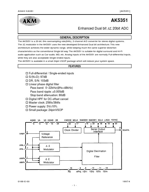
AK5351Enhanced Dual bit ∆Σ 20bit ADCGENERAL DESCRIPTIONThe AK5351 is a 20-bit, 64x oversampling rate(64fs), 2-channel A/D converter for stereo digital systems.The ∆Σ modulator in the AK5351 uses the new developed Enhanced Dual bit architecture. This new architecture achieves the wider dynamic range, while keeping much the same superior distortion characteristics as the conventional Single bit way. The AK5351 is suitable for digital surround and Hi-Fiaudio application such as Car-audio, MD, etc. Analog inputs of the AK5351 are normally Full-differential inputs, while they are also acceptable Single-ended inputs.The AK5351 is available in a small 24pin VSOP package which will reduce your system space.FEATURESFull-differential / Single-ended inputsS/(N+D): 97dBDR, S/N: 103dBLinear phase digital filterPass band: 0~22kHz(@fs=48kHz)Pass band ripple: ±0.005dBStop band attenuation: 80dBDigital HPF for DC-offset cancelMaster clock: 256fs/384fsPower supply: 5V±10%Small package: 24pinVSOPOrdering GuideAK5351-VF -40~85°C 24pin VSOPAKD5351/2 Evaluation BoardPin LayoutReplacement from AK5350 to AK5351AK5350AK5351Package 28VSOP 24VSOP*)Interchangeable with AK5350 Analog Inputs Voltage±3.47Vp-p±2.10Vp-p*)Acceptable Single-endedfc of HPF(@fs=48kHz) 7Hz 1HzSCLK ~64fs ~128fsPIN/FUNCTIONABSOLUTE MAXIMUM RATINGS(AGND,DGND=0V; Note 1 )Parameter Symbol min max UnitsDC Power Supply:Analog Power(VA pin) Digital Power(VD pin) (Note 2 ) Substrate Power(VB pin)VAVDVB-0.3-0.3-0.36.06.0/VB+0.36.0VVInput Current (Any pin except supplies)IIN-±10mA Analog Input VoltageAINL+,AINL-,AINR+,AINR-pins (Note 2 )VINA-0.3 6.0/VA+0.3V Digital Input Voltage (Note 2 )VIND-0.3 6.0/VB+0.3V Ambient T emperature T a-4085°C Storage T emperature Tstg-65150°C Note 1 : All voltage with respect to ground.Note 2 : Absolute maximum value is the highest voltage in 6.0V, VA+0.3V and VB+0.3V.WARNING: Operation beyond these limits may result in permanent damage to the device.Normal operation is not guaranteed at these extremes.RECOMMENDED OPERATING CONDITIONS(AGND,DGND=0V; Note 1 )Parameter Symbol min typ max UnitsDC Power Supplies: Analog Power Digital Power(VD pin)(VB pin) (Note 3 )VAVDVB4.504.504.505.05.05.05.50VB5.50VVVNote 1 : All voltages with respect to ground.Note 3 : The VA and VB are connected together through the chip substrate and have several ohms resistance. The VA and VB should be powered at the same time or earlier than VD.* AKM assumes no responsibility for the usage beyond the conditions in this data sheet.ANALOG CHARACTERISTICS(T a=25°C; VA,VD,VB=5.0V; fs=48kHz; 20bit; Input signal frequency=1kHz,Measurement Bandwidth=10Hz~20kHz; unless otherwise specified.)Note 4 :The ratio of the rms value of the signal to the sum of all other spectral components up to 20kHz except for the signal (included harmonic component, excluded DC component, analog inputsignal is -0.5dB). Inversed of THD+N.Note 5 :S/(N+D) with an input signal of 60dB below full-scale.Note 6 :When using only 20kHzLPF, S/N and DR are 99dB(typ.). When using CCIR-ARM filter, S/N is 99dB(typ.)Note 7 :Almost no current is supplied from VB pin.DIGITAL FILTER CHARACTERISTICS(T a=25°C; VA,VD,VB=5.0V±10%; fs=48kHz)Low Pass Filter characteristics Symbol min typ max UnitsPassband -0.005dB(Note 8 )-0.02dB-0.06dB PB021.521.76822.0kHzStopband (Note 9 )SB26.5kHz Passband Ripple (Note 10 )PR±0.005dB Stopband Attenuation (Note 9 ,Note 11 )SR80dB Group Delay Distortion∆ GD0us Group Delay (Note 12 )GD29.31/fs High Pass Filter characteristicsFrequency Response -3dB(Note 8 ) -0.5dB-0.1dB FR 1.02.96.5HzHzHzNote 8 :These frequencies scale with the sampling frequency(fs).Note 9 :Stopband is 26.5kHz to 3.0455MHz at fs=48kHz.Note 10 :Passband is DC to 21.5kHz at fs=48kHz.Note 11 :The analog modulator samples the input at 3.072MHz for a system sampling rate of fs=48kHz. These is no rejection of input signals at those bandwidths which are multiples ofthe sampling frequency (n x 3.072MHz ±22kHz ;n=0,1,2,3…).Note 12 :The calculation delay time occurred by digital filtering. This is the time from the input of analog signal to setting the 20bit data of both channels to the output registers. GD=29.3/fs.ELECTRICAL CHARACTERISTICSDigital Characteristics(T a=25°C; VA,VD,VB=5.0V±10%)Parameter Symbol min typ max UnitsHigh-Level Input voltage Low-Level Input voltage V IHV IL70%VD----30%VDVVHigh-Level Output voltage Iout=-20uA Low-Level Output voltage Iout=20uA V OHV OLVD-0.1----0.1VVInput Leakage Current (Note 13 )Iin--±10uA Note 13 :Except for pull-down and pull-up pins. TST1, TST2, TST3, TST4, SMODE2 pins have internal pull-down device, HPFE pin has internal pull-up devive(T yp. 50kΩ)SWITCHING CHARACTERISTICS(T a=25°C; VA,VD,VB=5.0V±10%; C L=20pF)In slave mode it becomes one LRCK clock(1/fs) longer.Timing ChartOPERATION OVERVIEWSystem clockIn slave mode, MCLK(256fs/384fs), LRCK(fs) and SCLK(64fs) are required for AK5351. Use a signal divided from the MCLK for LRCK. In master mode, only MCLK is needed. A LRCK clock rate meets standard audio rates (32kHz, 44.1kHz, 48kHz). In slave mode, the MCLK should be synchronized with LRCK but the phase is free of care.The AK5351 includes the phase detect circuit for LRCK clock, the AK5351 is reset automatically when the synchronization is out of phase by changing the clock frequencies. (Please refer to the "Asynchronization -reset."). When changing sampling frequency(fs) after power-up, AK5351 should be reset.During the operation (PD="H") following external clocks should never be stopped : CLK in master mode and MCLK, SCLK and LRCK in slave mode. When the clocks stop there is a possibility that the device comes into a malfunction because of over currents in the dynamic logic. If the external clocks are not present, the AK5351 should be in the power-down mode. (PD="L")Master Clock (MCLK)fsSCLK(64fs)256fs384fs32.0kHz8.1920MHz12.2880MHz 2.0480MHz44.1kHz11.2896MHz16.9344MHz 2.8224MHz48.0kHz12.2880MHz18.4320MHz 3.0720MHzT able 1 . System ClockClock CircuitCMODE MCLKL256fsH384fsAK5351 has an internal divider as shown in the above figure. The device can interface either or an external MCLK(256fs or 384fs) by controlling CMODE pin.Serial Data InterfaceAudio Serial Interface has four kinds of mode, it can be changed by SMODE1 and SMODE2 pins. Data format is MSB first, 2's complement.FigureSMODE1SMODE2Mode L/R polarityFigure 1L L Slave Mode: 20bit, MSB justified Lch=H, Rch=L Figure 2H L Master Mode: Similar to I 2S Lch=H, Rch=L Figure 3L H Slave Mode: I 2S Lch=L, Rch=H Figure 4H H Master Mode: I 2S Lch=L, Rch=HT able 2 . Serial Interface 1) SLAVE mode An output channel is defined by LRCK. Both channel data are output in sequence, in order of the Lch first then Rch at the rate of fs. Data bits are clocked out via the SDA T A pin at SCLK rate. Figure 1 and Figure 3 shows data output timing at SCLK=64fs. FSYNC enables SCLK to start clocking out data. The MSB is clocked out bythe LRCK edge. SCLK causes the ADC to output succeeding bits when FSYNC is high. However, as I 2S slavemode ignores FSYNC, it should hold "L" or "H".2) MASTER modeIn MASTER mode, the A/D converter is driven from a master clock(MCLK:256fs/384fs) and outputs all other clocks(LRCK, SCLK). The falling edge of SCLK causes the ADC to output each bit. Figure 2 and Figure 4shows the output timing. 2x fs clock of 50% duty is output via the FSYNC pin. FSYNC rises one SCLK cycle after the transition of LRCK edges and stays high during 16 serial clocks(16*t SLK ). Upper 16 bit data is output during FSYNC "H", lower 4 bit is output after FSYNC "L" transition.Figure 1 . Data Output Timing (Slave mode)Power-down modeThe AK5351 has to be reset once by bringing PD "L" upon power-up. All internal registers of the digital filter and so on in the AK5351 are reset by this operation. When exiting the power-down mode(PD="H"), the internal timing starts clocking by first MCLK "↑"(rising edge). In master mode internal counter starts at once, in slave mode internal counter starts after synchronizing with the first rising edge of LRCK. The serial output data is available after 516 counting clock of LRCK cycle.Asynchronization-resetIn slave mode, if the phase difference between LRCK and internal control signals is larger than +1/16~-1/16 of word period(1/fs), the synchronization of internal control signals with LRCK is done automatically at the first rising edge of LRCK.High Pass Filter(HPFE pin)The AK5351 has a Digital High Pass Filter(HPF) for DC-offset cancel. When HPFE pin goes "H", HPF is enabled. The cut-off frequency of the HPF is 1Hz(@fs=48kHz). It also scales with the sampling frequency(fs). The HPF can be disabled by bringing HPFE pin "L". In this case, the AK5351 has the DC-offset of a few mV.SYSTEM DESIGNFigure 5 shows the system connection diagram. Figure 6 and Figure 7 shows the input buffer circuit. An evaluation board[AKD5351/2] is available which demonstrates the optimum layout, power supply arrangement and measurement results.Figure 5 . System Connection Diagram ExampleNOTE: +5V Analog should be powered the same time or earlier than +5V Digital.Grounding and Power Supply DecouplingThe AK5351 requires careful attention to power supply and grounding arrangements. The VA and VB are connected together through the chip substrate and have several ohm resistance. The power to VB should come up at the same time or faster than the power to VD, when they are fed separately to the device (Figure 5). As to the connections of decoupling capacitors, refer to Figure 5 . The 0.1uF of decoupling capacitors connected power supply pins should be as near as possible to the power supply pin.As AIN± pins is near VD pin, ground pattern should be inserted between VD line and AINL± lines to avoid digital noise coupling. Refer to evaluation board manual of AKD5352/1 Rev.B about board layout.Analog signal is differentially input into the modulator via the AIN+ and the AIN- pins. The input voltage is the difference between AIN+ and AIN- pins. The full-scale of each pin is ±2.10Vp-p on its referencevoltage(VREF). In case that the positive input is more than its full-scale, the AK5351 outputs positive7FFFFH(Hex, Full-scale). In case that the negative input is more than its full-scale, the AK5351 outputs negative 80000H(Hex, Full-scale). Analog inputs of the AK5351 are normally Full-differential inputs, while they are also acceptable Single-ended inputs. In case of Single-ended inputs, analog signal is input from either positive or negative input and the other side inputs bias voltage. Figure 7 is a circuit example which analog input signal is input 4.20Vp-p into AIN- pin and bias voltage into AIN+ pin. The DC offset is removed by the internal HPF.AK5351 samples the analog inputs at 3.072MHz with fs=48kHz. The digital filter rejects all noise between 26.5kHz and 3.0455MHz. However, the filter will not reject frequencies right around 3.072MHz ( and multiples of 3.072MHz). Most audio signals do not have significant noise energy at 3.072MHz. Hence, a simple RC filter is sufficient to attenuate any noise energy at 3.072MHz.The reference voltage for A/D converter is supplied from the VREF pin at VA reference. In order to eliminate the effects of high frequency noise on the VREF pin, a 10uF or less electrolytic capacitor and a 0.1uF ceramic capacitor should be connected parallel between the VREF and the VA pins. No current should be driven from the VREF pin.The AK5351 accepts +5V supply voltage. Any voltage which exceeds the upper limit of (VA+)+0.3V and lower limit of AGND-0.3V and any current beyond 10mA for the analog input pins(AINL±, AINR±) should be avoided. Excessive currents to the input pins may damage the device. Hence input pins must be protected from signals at or beyond these limits.Use caution specially in case of using ±15V in surrounding analog circuit.Figure 6 . Full-differential Input Buffer Circuit ExampleFigure 7 . Single-ended Input Buffer Circuit ExampleT o minimize digital originated noise, connect the ADC digital outputs only to CMOS inputs. Logic families of 4000B, 74HC, 74AC, 74ACT and 74HCT series are suitable.Multiple AK5351In systems where multiple ADC's are required, care must be taken to insure the internal clocks are synchronized between converters to make simultaneous sampling. In slave mode, synchronous sampling is achieved by supplying the same MCLK and LRCK to all converters. In master mode, the same PD signal is supplied to each ADC. The PD state is released at the first rising edge of MCLK after bringing PD into high. Hence, if the rising edge of PD and rising edge of MCLK coincides together the sampling difference among the ADC's modulator would occur. The difference could be 1/256fs in the sampling clock(64fs) of the modulator, typically 81ns at fs=48kHz.z 24pin VSOP (Unit: mm)Material & Lead finishPackage:EpoxyLead-frame:CopperLead-finish:Soldering plateContents of AAXXXX AA:Lot#XXXX:Date Code。
介绍一下mp3的解码器
fzhhjzs]去年才出现在市场上的韩国Telechips解码芯片,一经面世便获得一致好评,在韩国众多厂商的大力支持下成长迅速。
从功能、性能、音质各方面来看,Telechips TCC730/ 731比Sigmatel的STMP3410之类的芯片着实要好一些,低音感充足、各频段表现比较平衡、而且音场更为宽阔;但与飞利浦SAA7750/7751相比还有一定差距。
另外,Tele chips TCC730价格比SAA7750便宜一点,但需要外接ROM,外围元件比较多,因此采用这种芯片的MP3产品难得有身材玲珑的产品面世。
业界普遍认为Telechips芯片各方面表现介于Sigmatel STMP3410和SAA7750/7751系列之间。
采用该芯片的MP3在本身的音质基础上,如果配备了更为高档的耳机后还会有一定的提升。
该类型的机子一般会标配森海塞尔MX300(或者OEM森海塞尔)耳机,该耳机属于森海塞尔普及型MX系列中最平民化的耳机,所以建议对音质有更高要求的朋友可以尝试森海塞尔MX500,或者更高档一点的KOSS SP/KOSS PP,森海塞尔PX 100/PX200。
因为采用该芯片的MP3在音质上有一定的潜力,而并不像所有经销商告诉你的,所有的MP3在更换高档耳机后音质都有提升,其实有些MP3自身芯片及设计,生产工艺的限制使得其已经不具有音质的挖掘空间。
Sigmatel系列产地:美国如果要说目前MP3芯片市场占有率的话,那么美国的Sigmatel家族肯定是名至实归,但对于Sigmatel芯片的品质,却总是仁者见仁,智者见智。
总体而言采用Sigmatel解码芯片的MP3音质表现会中规中矩,声音比较亮丽,中音表现一般,低音量感不足、高音比较生硬,它在音乐的表现上要逊于飞利浦和Telechips芯片。
1、Sigmatel 3410曾几何时,SigmaTel 3410的芯片还占据着MP3芯片市场的半壁江山,可能直到目前S TMP3410单芯片方案仍然是最成熟和常见的一种方案。
1-440133-1资料

1-440133-1 Product DetailsHome | Customer Support | Suppliers | Site Map | Privacy Policy | Browser Support© 2008 Tyco Electronics Corporation All Rights Reserved SearchProducts Documentation Resources My Account Customer SupportHome > Products > By Type > 1mm -1.5mm Centerline > Product Feature Selector > Product Details1-440133-1Active High Performance Interconnects (HPI)Always EU RoHS/ELV Compliant (Statement of Compliance)Product Highlights:? 2.50 mm Centerline?Receptacle?Number of Positions = 11?Housing Color = Natural?Number of Rows = SingleView all Features | Find SimilarProductsCheck Pricing &AvailabilitySearch for ToolingView MatingProducts (4)Product FeatureSelectorContact Us AboutThis ProductQuick LinksDocumentation & Additional InformationProduct Drawings:? 2.5MM PITCH HPI CRIMP HOUSING.(PDF, English)Catalog Pages/Data Sheets:?None AvailableProduct Specifications:?Metric Interconnect System (Restricted to Sony Corpo...(PDF, English)Application Specifications:?None AvailableInstruction Sheets:?None AvailableCAD Files:?None AvailableList all Documents Additional Information:?Product Line InformationRelated Products:?Tooling?Mating Products (4)Product Features (Please use the Product Drawing for all design activity)Product Type Features:?Product Type = Receptacle?Number of Positions = 11Body Related Features:?Centerline (mm [in]) = 2.50 [0.098]?Number of Rows = SingleHousing Related Features:?Housing Color = Natural?Housing Flammability Rating = UL 94V-0 ?Housing Material = Nylon 66 Industry Standards:?RoHS/ELV Compliance = RoHS compliant, ELVcompliant?Lead Free Solder Processes = Not relevant forlead free process?RoHS/ELV Compliance History = Always wasRoHS compliantOther:?Brand = AMPProvide Website Feedback | Contact Customer Support。
L7751型智能型重锤操作手册(中英文对照版)
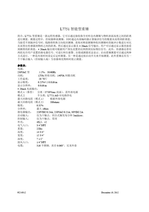
参数表:
电源:
230VAC 型
±5%,50/60Hz
功耗:
12VA 持续功耗,140VA 间歇功耗
工作温度:
-20-70℃
显示精度:
0.25%+±0.01ft/m
显示分辨率: 0.01ft/m
4-20mA 电流输出:
模式 1(推荐) 分离(3750Vrms 浪涌),需外部电源
模式 2
不分离,L7751 AO 对电路供电
5
最大释放量程——此菜单可设置重锤的最大量程,即重锤放下的最大距离,量程为 0.11 至 124.84 米。默认值为 18 米。
继电器 1 输出——常开继电器,可设置成以下任意功能: 失效(默认状态) 高位报警(释放)——0.00 至 124.84 米 低位报警(释放)——0.00 至 124.84 米 出错报警 测量状态显示 继电器 2 输出——同继电器 1 输出。
传感器
容器
中心入料口
连接和接线 所有现场连接应当符合当地或国家相关规定,升温速率最低 85℃。接线及跳接器设置前需切断电 源。 电源 为保证安全,必须先断开电源。电源连接请参照下图。电源线连接至马达安装支架上方两个端口。 左边端口连接线路导线,右边端口连接负极。 电源接口左边为接地线端口,设备必须连接接地线路。接地线路可对电路进行有效保护,避免可能 因静电、或控制及启动输入时发生的浪涌现场造成的损坏。一般建议将电源线纳入金属导管。
安装位置
满位
空位
马达驱动模式 按 CYCLE 键,可进行一个完整的检测测量过程,这个过程中 4-20mA 和继电器将不根据测试结果更新 输出。 持续按 DOWN 键,释放测锤。放开 DOWN 键时,将停止释放重锤,当测锤碰到物料或料仓底部时也 将停止释放。 持续按 UP 键,可收回测锤 。放开 UP 键或当测锤完全收回时将自动停止收回。 START 端短路可启动一次真正的测量。 缆绳调换指南: 准备工作,切断电源,将外壳后背盖子打开。 缆绳调换: 1. 按线路板顶部“CYCLE”键,把缆绳从供线滑轮上移开。保持缆绳拉紧的同时,把缆绳从滑轮上拉下
C7521材料俗称叫法是什么具体成分标准是多少

C7521标准 JIS H3110-2012白铜是以镍为主要添加元素的铜基合金,呈银白色,有金属光泽,故名白铜。
铜镍之间彼此可无限固溶形成连续固溶体,即不论彼此的比例多少,而恒为α--单相合金。
当把镍熔入红铜里,含量超过16%以上时,产生的合金色泽就变得洁白如银,镍含量越高,颜色越白。
白铜中镍的含量一般为25%。
铸造温度1170℃;退火温度700~750℃;轧制热加工温度950~970℃;消除内应力的低温退火温度250℃应用产品广泛用于电器、电子、电力、汽车、通讯、五金等行业,如变压器铜带、引线框架材料带、射频电缆带、太阳能光伏铜带、高炉用铜冷却壁板、含银无氧铜板、电子接插件铜带、模具电极铜板、乐器铜板等。
白铜特性及用途:白铜因耐蚀性优异,主要应用与海水淡化蒸发管,中央空调冷凝管,船舶空冷器,石化冷却器,电站汽轮机凝汽器等重点工业领域。
白铜是以镍为主要添加元素的铜基合金,呈银白色,有金属光泽,故名白铜。
铜镍之间彼此可无限固溶,从而形成连续固溶体,即不论彼此的比例多少,而恒为单相合金。
当把镍熔入红铜里含量超过16%以上时,产生的合金色泽就变得相对近白如银,镍含量越高,颜色越白,但是,毕竟与铜融合,只要镍含量比例不超过70%,肉眼都会看到铜的黄色。
何况通常白铜中镍的含量一般为25%。
铜镍合金公司采用先进的加工百工艺,按照德标、欧标、美标、国标等标准要求设计制造。
主要产品包括CuNi90/10、CuNi70/30铜镍法兰、管材、弯头、三通、度异径管、锻制管件等,规格从通径DN15-DN500。
公司专注于为石油、船舶、化工、核工业、水处理、建筑等领域的客户提供全方案的管件产品服属务,以支持客户提升自身品牌价值。
复杂白铜加有锰、铁、锌、铝等元素的白铜合金称复杂白铜(即三元以上的白铜),包括铁白铜、锰白铜、锌白铜和铝白铜等。
在复杂白铜中,第二个主要元素符号及铜含量以外的成分数字组表示各种元素的含量。
如BMn3-12表示镍含量约为3%,锰含量约为12%。
DINEN755-1
铝和铝合金挤压棒材/条材, 管材及型材第一部分: 检验与交货的技术条件EN755-1ICS 77.150.10关键词: 铝, 棒, 条, 管, 型材.欧洲标准EN 755-1:德国标准1997年版本前言此标准由CEN/TC 132 编制负责编制的德国组织有:有色金属标准委员会,铝合金技术委员会修正1983年2月出版的DIN 1746-2, DIN 1747-2和DIN 1748-2由EN 754-1和EN 755-1所取代.前版DIN 1746-2: 1963-07, 1968-12, 1983-02; DIN 1747-2: 1968-12, 1977-07, 1983-02; DIN 1748-2: 1962-05, 1968-12, 1983-02.ICS 77.150.10描述: 铝, 棒, 条, 管, 型材.铝和铝合金挤压棒材/条材, 管材及型材第一部分: 检验与发货的技术条件此标准在1998年3月10日由CEN(欧洲标准化委员会) 批准.欧洲标准化委员会的成员必须遵循欧洲标准化委员会/欧洲电工标准化委员会(CEN/CENELEC)的内部规定:在没有任何变更的前提下给予本欧洲标准与国家标准同等地位的条件。
有关这些国家标准的最新清单及参考书目可向中央秘书处或任何欧洲标准化委员会申请获得.CEN 会员由奥地利, 比利时, 捷克斯洛伐克, 丹麦, 芬兰, 法国, 德国, 希腊, 冰岛, 爱尔兰, 意大利, 卢森堡, 北爱尔兰, 挪威, 葡萄牙, 西班牙, 瑞典, 瑞士, 及英国的国家标准组织所构成.前言此标准由CEN/TC 132 “铝和铝合金”技术委员会所编制.其中, 技术委员会CEN/TC 132 编制了关于“挤压和冷拉产品”的下列标准:EN 755-1 铝和铝合金-挤压棒材/条材, 管材及型材第1部分: 检验与交货的技术条件此标准是下列标准中的一部分:EN 755-2 铝和铝合金-挤压棒材/条材, 管材及型材第二部分: 力学性能EN 755-3 铝和铝合金-挤压棒材/条材, 管材及型材第三部分: 圆棒-尺寸和形状公差。
- 1、下载文档前请自行甄别文档内容的完整性,平台不提供额外的编辑、内容补充、找答案等附加服务。
- 2、"仅部分预览"的文档,不可在线预览部分如存在完整性等问题,可反馈申请退款(可完整预览的文档不适用该条件!)。
- 3、如文档侵犯您的权益,请联系客服反馈,我们会尽快为您处理(人工客服工作时间:9:00-18:30)。
Mimix Broadband’s SMaRTPAK (Standard Microwave Radio TWT replacement Power Amplifier Kit) amplifiers are uniquely designed to combine the DC/DC Converter, microwave amplifier and cooling devices into one single integrated unit. Each unit has been designed using modern device technology and includes reverse polarity,
overvoltage and excess thermal protection. Unlike TWT's and other TWT replacement options, SMaRTPAKs do not require a separate, bulky and often unreliable power supply.
All units are designed to directly drop-in place of existing TWT or SSPA units with no modifications saving
significant time and effort. Using the proper equipment, unit installations and alignment can typically be done almost effortlessly in less than an hour. It is r ecommended that all first time users have a Mimix Broadband representative present during initial installation. Ask us about our onsite installation and alignment options.Mimix is confident that you will be pleased with our product and each unit comes with a standard five-year warranty. If you do not see a part number that covers your desired frequency , power or radio type, feel free to contact us and we will gladly review your requirements.
Description:
GTE Lenkurt 775 11 GHz TWTA SSPA Replacement Kits
Features:
Units operate over the full 10.7-11.7 GHz frequency range 5 and 10 Watt output power levels are available Simple and easy Installation Instructions are included
Standard 5-Y ear Warranty
1003031- 5W
Units Min Typ Max GHz 10.7-11.7dB --14.0-9.5ohms -50-dB 45.050.0-dB
-+/-0.5+/-1.0dB -8.010.0dBm --12.0+5.0dBm +37.0+38.0----dBc --70.0dBc --60.0
o -20C
-+70
0.0%
-950.0ft -16,0000.0ft -60,000-21.0V --56.0-A
6.5
7.0
Min Typ Max 10.7-11.7--14.0-9.5-50-45.050.0--+/-0.5+/-1.0-8.010.0--12.0+5.0+40.0+41.0------70.0--60.0-20-+700.0-950.0-16,0000.0-60,000-21.0--56.0-10.5
11.0
1006508 - 10W
Parameter Frequency Range Input Return Loss
Input/Output Impedance Gain
Gain Flatness Noise Figure Input Power
Output Power (P1dB)Spurious Harmonics
Base Operating T emperature Humidity (Non-Condensing)Altitude (Operating)Altitude (Storage)DC Power
DC Current @ +12 Volts
o Electrical Characteristics (T=25C)
Specifications are subject to change without notice. Export of this item may require appropriate export licensing from the U.S. Government. In purchasing
these parts, U.S. Domestic customers accept their obligation to be compliant with U.S. Export Laws. Revision-02-May-02
Mimix Broadband, Inc. 10795 Rockley Rd. Houston, Texas 77099Tel: 281.988.4600 Fax: 281.988.4615
元器件交易网。
