RYT-050909中文资料
温州瑞基电动执行器选型样本-RJ智能型选型安装使用说明讲解

转 矩
行程
时间
60/50Hz
阀 门
最 大
轴 径
电机
功 率
(F级)
额定电流
手轮
转数
重量
三相380V/440V
N.m
N.m
s
mm
W
A
n
kg
RJ/RJM06
60
50
14/17
22
15
0.25/0.14
8.5
11
RJ/RJM09
90
75
14/17
22
25
0.28/0.20
8.5
11
RJ/RJM15
150
输 出
转 矩
调 节
转 矩
行程
时间
60/50Hz
阀 门
最 大
轴 径
电机
功 率
(F级)
额定电流
手轮
转数
重量
单相110V/220V
N.m
N.m
s
mm
W
A
n
kg
RJM06
50
25
14/17
22
15
1.00/0.45
8.5
11
RJM09
80
40
14/17
22
25
1.30/0.58
8.5
11
RJM15
130
70
mm
螺孔规格
螺孔深度
mm
RJ06、RJ09
F07
70
4-M8-6H
12
RJ15、RJ19
F07
70
4-M8-6H
15
F10
RTS-0509中文资料
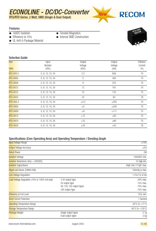
ECONOLINE - DC/DC-Converter
RTS/RTD Series, 2 Watt, SMD (Single & Dual Output) Package Style and Pinning (mm)
Dual Output Single Output
3rd angle projection
Efficiency at Full Load Short Circuit Protection Operating Temperature Range Storage Temperature Range Package Weight
元器件交易网
Dual –Vin +Vin Com –Vout +Vout No Pin NC
XX.X ± 0.5 mm XX.XX ± 0.25 mm
EC 50
August 2002
Specifications (Core Operating Area) and Operating Temperature / Derating-Graph
Input Voltage Range Output Voltage Accuracy Rated Power Isolation Voltage Isolation Resistance (Viso = 500VDC) Isolation Capacitance Ripple and Noise (20MHz BW) Line Voltage Regulation Load Voltage Regulation (10% to 100% full load) 3.3V output type 5V output type 9V, 12V, 15V output types 24V output type ±10% ±5% 2W 1000VDC min. 10 GΩ min. 40pF min./115pF max. 150mVp-p max. 1.2%/1% of Vin 20% max. 15% max. 10% max. 10% max. 70% min. 1 Second -40°C to +71°C -55°C to +125°C Single output types Dual output types August 2002 2.1g 2.5g EC 49
吸塑油知识

吸塑油知识公司内部编号:(GOOD-TMMT-MMUT-UUPTY-UUYY-DTTI-吸塑油RY5050特种吸塑油固含量: 约45±1%粘度(25℃) :1200-1500特性: 渗透性能优异,对PVC吸力强劲,品质稳定可靠使用方法 "联机或脱机上光,适量添加稀释剂(甲苯、醋酸乙酯等),建议按1:1稀释。
用途广泛用玩具,牙膏、五金、化妆品等行业的保质期 1、油墨发须充分干燥,否则溶剂会稀释油墨而掉色。
2、遇白卡纸等特殊纸质应先作试验,不可双面涂布。
专有清洁剂清洗耳恭听机器和工具。
3、热风干燥完全,以免影响亮度RY5051强力吸塑油固含量: 约45±1%粘度(25℃) :1200-1500特性:渗透性能优异,对PVC吸力强劲,具有良好的磨光效果。
使用方法:联机或脱机上光,适量添加稀释剂(甲苯、醋酸乙酯等),建议按1:1稀释。
用途:广泛用玩具,牙膏、五金、化妆品等行业的吸塑包装保质期1、油墨发须充分干燥,否则溶剂会稀释油墨而掉色。
2、遇白卡纸等特殊纸质应先作试验,不可双面涂布。
专有清洁剂清洗耳恭听机器和工具。
3、热风干燥完全,以免影响亮度。
UV哑油哑光型上光油光泽度为30度左右,可根据客户具体需求进行调配。
光泽度柔和、磨面平整、上光过程不粘粉在胶辊且上光后具有良好的抗反粘性和抗湿性,具有良好的印刷油墨密着性。
环保无毒,上光时易清洗。
高耐磨型上光油高耐磨上光油具有高滑爽,高耐磨,中等光泽的特点,优异的手感.其表面更耐水.本产品呈微黄乳白色液体,突破上光油的致命缺点耐磨性不好,从而造成印刷包装制品运输过后油墨破坏的现象。
本产品在4磅耐磨仪器上检测400次无油墨破坏(可根据客户具体需求进行调配),而普通同类产品只可达到30次左右。
使用该产品将使您的包装制品具有极强的竞争力。
上光后具有良好的流平性。
磨光吸塑油磨光吸塑油上油后具有优良的光泽度,对PVC片具有良好的吸塑力,应用纸张广泛,安全无毒。
ACWU90型电缆知识
ACWU90型是一种高柔韧性的自锁型铝铠装、PVC外护套、90℃交联聚乙烯防水型绝缘单芯或多芯电缆,附一根等电位联结裸导线(可选)。
因为具有FT4级的PVC外护套,ACWU90可直接埋地敷设,并使用于腐蚀环境和非燃性建筑中。
ACWU90减少了管道布线所带来的施工难度和人力成本。
电缆已在工厂用高柔韧性的自锁型铝铠装和密封PVC外护套组装完毕,不需要管道及其附件和人工密集的拉线、扣纹和成管等工序。
ACWU90通过CSA 认证可应用于干燥和潮湿环境的明线或暗线敷设,也可应用于1区和2区1级危险环境,以及2、3级危险环境。
敷设方式室内可采用支架、梯架、托盘以及电缆夹明敷,户外可采用直埋、电缆沟、电缆隧道等多种方式。
ACWU90每米设有标定标记,以便准确地确定电缆长度。
STABILOY ACWU90多芯电缆的截面规格从25mm2到400mm2。
它完全符合IEC 60502.1、GB 12706.1的规范标准。
加铝还根据客户要求提供各规格的低烟无卤型产品。
应用于干燥和潮湿环境的明线或暗线敷设,也可应用于1区和2区1级危险环境,以及2、3级危险环境。
敷设方式室内可采用支架、梯架、托盘以及电缆夹明敷,电线电缆型号介绍行业:电工电气,电子元器件信息来源:安徽天康发布时间:2010-12-23打印转发关闭电线电缆型号介绍一、电缆的型号由八部分组成:一、用途代码-不标为电力电缆,K为控制缆,P为信号缆;二、绝缘代码-Z油浸纸,X橡胶,V聚氯乙稀,YJ交联聚乙烯三、导体材料代码-不标为铜,L为铝;四、内护层代码-Q铅包,L铝包,H橡套,V聚氯乙稀护套五、派生代码-D不滴流,P干绝缘;六、外护层代码七、特殊产品代码-TH湿热带,TA干热带;八、额定电压-单位KV二、电线电缆命名、电线电缆产品的命名有以下原则:电线电缆的完整命名通常较为复杂,所以人们有时用一个简单的名称(通常是一个类别的名称)结合型号规格来代替完整的名称,如“低压电缆”代表0.6/1kV级的所有塑料绝缘类电力电缆。
50990资料

50990 Product DetailsHome | Customer Support | Suppliers | Site Map | Privacy Policy | Browser Support© 2008 Tyco Electronics Corporation All Rights Reserved SearchProducts Documentation Resources My Account Customer Support Home > Products > By Type > Product Feature Selector > Product Details50990Active AMPOWER TerminalsAlways EU RoHS/ELV Compliant (Statement of Compliance)Product Highlights:?Power Generation and DistributionApplication?Wire Size (AWG/CM) = 2/0 AWG [67-70²]?Wire Range = 119500 -150500 CMA?Terminal Type = Standard?Stud Size = 5/16 [M8]View all Features | Find SimilarProductsCheck Pricing &AvailabilitySearch for ToolingProduct FeatureSelectorContact Us AboutThis ProductQuick LinksDocumentation & Additional InformationProduct Drawings:?TERMINAL, AMPOWER, WIRE SIZE: 2/0 AWG(PDF, English)Catalog Pages/Data Sheets:?None AvailableProduct Specifications:?None AvailableApplication Specifications:?None AvailableInstruction Sheets:?None AvailableCAD Files:?None AvailableList all Documents Additional Information:?Product Line InformationRelated Products:?ToolingProduct Features (Please use the Product Drawing for all design activity)Product Type Features:?Terminal Type = Standard?Stud Size = 5/16 [M8]?Stud Diameter (mm [in]) = 7.92 [0.312]?Material = Copper (Annealed) per ASTM B-75?Body Style = Straight?Tongue Material Thickness (mm [in]) = 2.79[0.110]?Finish = Tin?Comment = Electrodeposited Tin Plate per MIL-T-10727.Body Related Features:?Wire Size (AWG/CM) = 2/0 AWG [67-70²]?Wire Range (CMA) = 119,500 –150,500?Stud Hole Diameter (mm [in]) = 8.33 [0.328]?Number of Holes = 2?Barrel I.D. Min. (mm [in]) = 13.03 [0.513]?Barrel Length = Standard?Inspection Slot = With Industry Standards:?RoHS/ELV Compliance = RoHS compliant, ELVcompliant?Lead Free Solder Processes = Not relevant forlead free process?RoHS/ELV Compliance History = Always wasRoHS compliantOperation/Application:?Application = Power Generation andDistributionPackaging Related Features:?Packaging Quantity = 50Other:?Brand = AMPProvide Website Feedback | Contact Customer Support。
法国溯高美低压产品介绍

熔断器开关 Fuserbloc 32 – 1250 A
• Fuserbloc 32 – 1250 A
主要特点:
• 模块化设计,每极1个模块 • 63A 以下导轨固定 • IP2 (熔断器盖和端子盖) • 试验位子为标准配置 ( 400A以下 ) • 1 至 21 极 • 直接操作 • 正面柜外操作 • 侧面操作 (左侧和右侧) • 可设置辅助触点 • 熔断指示 • 背面连接
正常 / 应急控制 器
ATyS 6
ATyS 3
ATyS C20/C30/C40
SWITCHING RANGE GB 10/2005
ATyS 系列电流等级
ATyS 3:
ATyS 3s : 125 – 1800A,3P/4P 10个电流等级 ATyS 3e : 2000 – 3200A,3P/4P 3个电流等级
SWITCHING RANGE GB 10/2005
熔断器开关 Fuserbloc CD 25 – 32 A
Disconnectable Neutral
GB/DIN:
25A 和 32A (熔断器尺寸: 10x38 和 14x51) 3 极和 3极+ 开关或固定中心极
附件:
• 直接和柜外手柄 • 可断开中性极 • 熔断器熔断指示( DIN 尺寸14x51) • U 型辅助触点模块 • 模块化辅助触模块 • 2x2 可设置 U 型辅助触点
SWITCHING RANGE GB 10/2005
熔断器开关
FUSERBLOC 系列 25 – 1250 A
SWITCHING RANGE GB 10/2005
熔断器开关 Fuserbloc CD 25 – 32 A
RY全系列规格书

RY detating curve
第2页 共7页
面通知
RY 金属氧化膜固定电阻器产品规格书
RYG derating curve 3-2 额定电压 Rated voltage 用标称阻值和额定功耗乘积的平方根计算出来的直流或交流有效值电压。 The d.c. or a.c.r.m.s. voltage calculated from the square root of the product of the rated resistance and the E= PR E:额定电压 Rated voltage(V) P:额定功率 Power rating(W) R:阻值 Nominal resistance(Ω) 额定电压不大于最大连续工作电压 In no case shall the rated voltage be greater than the applicable maximum continuous working voltage. 4、外形尺寸构成图 Dimensions & structure 4-1 外形尺寸 Dimensions
南 京 先 正 电 子 有 限 公 司
Nanjing Shagon Electronics Co.,Ltd 金属氧化膜固定电阻器产品规格书 Metal Oxide Film Fixed Resistors Specifications
产品规格 Type:
RY14、RY15、RY16、RY17、RY18,RYGx,RYG RYL14、RYL15、RYL16、RYL17、RYL18
安装方法:见本规范 1.1 条 Method of mounting:see specification 程序:B 4 Procedure: B 4
Y-050润滑油
一、物品與廠商資料物品名稱: 乾性潤滑劑 Dry Lubricant 物品編號: A-1319供應商名稱:台灣富見雄事業股份有限公司 供應商地址:台北市新湖二路 168 號 5 樓供應商電話/傳真:TEL :02-8791-2333 FAX :02-8792-6333 緊急聯絡電話/傳真電話:TEL :02-8791-2333 FAX :02-8792-6333 二、危害辨識資料 健康危害效應:一般性的取用不具危險性。
物理性及化學性危害:非危險物。
特殊危害: 常溫無特殊危害,但完全密閉環境高溫加熱 (約300℃以上)會產生HF 及PFIB 之有害性分解物。
最重要危害效應主要症狀:常溫無症狀,但高溫分解物吸入會引起呼吸道感染症狀。
物品危害分類:非危險物,無GHS 標識圖示。
警示語:無。
三、成分辨識資料 混合物:中英文名稱: 合成氟系潤滑劑 同義名稱: Fluorine Lubricant化學文摘社登記號碼(CAS No.):企業秘密危害物質成分(成分百分比):Not contain 。
PRTR 法(化學物質管理促進法) 非危險物 化學性質:成分之英文名稱 成分百分比 Hydrofluoroether 90 - 100 Fluoroadditives0 - 10四、急救措施不同暴露途徑之急救方法:(常溫使用)˙ 吸入:若有症狀出現,緊急移至安靜涼爽、通風良好的地方。
˙ 皮膚接觸:移除受污染衣物後,用清水及肥皂清洗。
˙ 眼睛接觸:直接以清水沖洗至少15分鐘,再請眼科醫師檢查。
˙ 食入:一般不需特別應急措施;用大量乾淨之飲用水漱口亦可。
˙ 有關應急措施特記事項:本潤滑劑在室溫中對眼睛、皮膚、呼吸道基本上並無刺激作用,但在使用或保存過程中,若不慎混入外來之污染異物,造成本劑污染,而使身體沾附,請儘速將沾附於眼睛、皮膚、呼吸道的污染異物清除,這是最基本的緊急處理方法。
對急救人員之防護:一般正常裝備即可。
Amodel_PPA_fuel_rail燃油测试

1.00E+06
Cycles to Failure
1.00E+07
33% GR PPA 40% GR PPS
33% GF PA66
Amodel PPA在抗疲劳性上优于PPS & PA66
© 2009 Solvay Advanced Polymers, LLC BUSINESS CONFIDENTIAL
Amodel PPA 在燃料浸泡后没有明显的聚合物降解。
© 2009 Solvay Advanced Polymers, LLC BUSINESS CONFIDENTIAL
3
SOLVAY ADVANCED POLYMERS
Amodel A/AS-1133 HS 甲醇燃油测试 燃料定义 (SAE J-1681):
Fuel C = 50% 异辛烷Iso-octane + 50% 甲苯Toluene Fuel CM 15 = 85% Fuel C + 15% 甲醇Methanol Fuel CM 30 = 70% Fuel C + 30% 甲醇Methanol Fuel CM 85 = 15% Fuel C + 85% 甲醇Methanol
IV (dl/g)
0.89 0.90 100 100 1.46 1.47
1.04 1.04 100 100 1.45 1.45
1.01 1.03 100 100 1.45 1.45
0.88 0.88 100 100 1.45 1.44
0.98 0.99 100 100 1.44 1.44
IV and crystallinty 都在可以接受的范围显示了Amodel PPA 在长期 的乙醇和甲醇燃油中浸泡后仍能保持很好的机械性能。
INA FAG轴承样本中文版-推力滚针轴承

876 HR 1
Schaeffler Group Industrial
最小轴向载荷
垫圈的方向 精度
轴承组件的 公差
公差
对于最小轴向载荷 Fa min 必须按照下式计算。
Fa min
=
0.0005 ⋅ C 0a
+
ka
⎛ ⎝⎜
C0a ⋅n 108
⎞2 ⎠⎟
F最a 小min轴向载荷
N
k确a定最小载荷的系数;– ka = 3
HR 1 877
108 074a 108 071c
推力滚针和保持架组件 推力轴承垫圈
Dw
B1
Dc Dc1
Eb Ea
D
d
AXK
AS
尺寸表 · 单位:mm
推力滚针和保持架组件
型号
质量 m
AXK0414-TV
Ϸg 0.7
AXK0515-TV
0.8
AXK0619-TV
1
AXK0821-TV
2
AXK1024
疲劳极限载荷 Cua
N 940
1 070 1 580 1 970 2 500 2 850 3 600 3 950 4 750 5 900 7 100 8 300 11 800 13 300 14 800 20 300 26 500 28 500 26 500 28 000 29 500 30 500 44 500 58 000 63 000 68 000 75 000 79 000 82 000 86 000
极限转速 nG
min–1 21 500 20 600 18 900 17 800 16 900 15 200 13 200 12 100 10 500
长城低温润滑脂参数表-概述说明以及解释
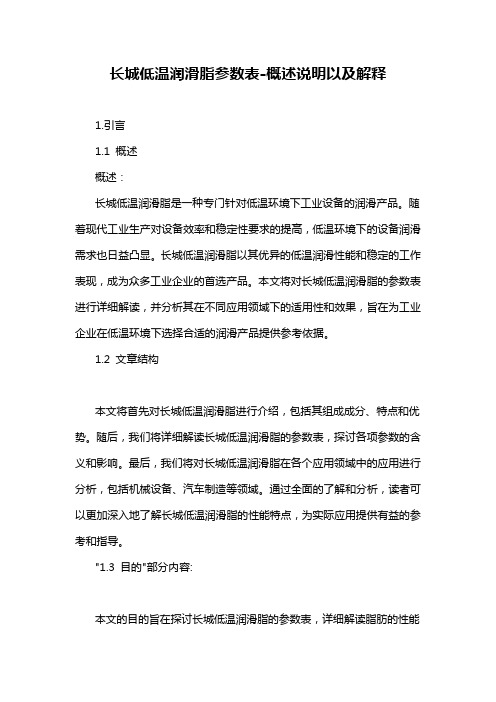
长城低温润滑脂参数表-概述说明以及解释1.引言1.1 概述概述:长城低温润滑脂是一种专门针对低温环境下工业设备的润滑产品。
随着现代工业生产对设备效率和稳定性要求的提高,低温环境下的设备润滑需求也日益凸显。
长城低温润滑脂以其优异的低温润滑性能和稳定的工作表现,成为众多工业企业的首选产品。
本文将对长城低温润滑脂的参数表进行详细解读,并分析其在不同应用领域下的适用性和效果,旨在为工业企业在低温环境下选择合适的润滑产品提供参考依据。
1.2 文章结构本文将首先对长城低温润滑脂进行介绍,包括其组成成分、特点和优势。
随后,我们将详细解读长城低温润滑脂的参数表,探讨各项参数的含义和影响。
最后,我们将对长城低温润滑脂在各个应用领域中的应用进行分析,包括机械设备、汽车制造等领域。
通过全面的了解和分析,读者可以更加深入地了解长城低温润滑脂的性能特点,为实际应用提供有益的参考和指导。
"1.3 目的"部分内容:本文的目的旨在探讨长城低温润滑脂的参数表,详细解读脂肪的性能指标和应用要点。
通过对参数表的分析,读者可以深入了解长城低温润滑脂的优势和适用范围,帮助用户正确选择和应用该产品,提高设备运行效率,延长设备使用寿命。
同时,本文也旨在促进长城低温润滑脂的市场推广和应用推动,为工程领域和润滑行业的发展做出贡献。
2.正文2.1 长城低温润滑脂介绍长城低温润滑脂是一种专为低温环境下的润滑需求而设计的润滑脂产品。
在极寒的环境中,常规润滑脂可能会失去润滑性能,导致设备运行不稳定甚至损坏。
因此,长城低温润滑脂具有优异的低温性能,能够在-40以下的极端条件下保持稳定的润滑效果。
长城低温润滑脂采用特殊的配方,使其在低温下不会变硬或流动性差,保持黏度适中,确保润滑油膜的形成和维持,有效减少设备在低温环境下的磨损和摩擦。
其优异的抗氧化性和耐极端压力性能也使其在严苛的工况下表现出色。
长城低温润滑脂广泛应用于冷藏设备、食品加工设备、航空航天、汽车制造等低温环境下的设备和机械中,为设备的稳定运行提供保障。
油缸密封选型指南
大连仟丰贸易有限公司技术部
大连仟丰贸易有限公司
格来圈工况条件
工作压力: ≤ 80Mpa; 往复速度: ≤ 15m/s; 工作温度:-45 ℃ ~+200℃(取决于O形圈材质) 工作介质:石油基液压油、难燃液压油、环保安全液(生物 油)等 产品材质:PTFE、NBR、FKM等 设计标准:TRELLEBORG、PARKER
大连仟丰贸易有限公司技术部
大连仟丰贸易有限公司
金属骨架防尘工况条件
往复速度: ≤ 1m/s; 工作温度:-40 ℃ ~+110℃ 工作介质:矿物油、难燃液压油、水 产品材质:PU、NBR及金属件 设计标准: TRELLEBORG、PARKER
大连仟丰贸易有限公司技术部
大连仟丰贸易有限公司
4、轻载四氟防尘圈是由一个用聚四氟乙烯加青铜粉材料制作的防尘圈和 一个作为弹性施力的O形圈组成,当活塞杆外伸时,能挡住介质侧的 剩余油膜。
大连仟丰贸易有限公司技术部
大连仟丰贸易有限公司
导向耐磨环工况条件
材料:PD 速度:往复运动≤15m/s 温度:-60℃~+200 ℃ 表面支承压力:最大为15N/m㎡ 材料:PHCD 速度:往复运动≤1m/s 温度:-50℃~+130 ℃ 表面支承压力:最大为90N/m㎡
大连仟丰贸易有限公司技术部
大连仟丰贸易有限公司技术部
大连仟丰贸易有限公司
斯特封特点 ※极小的启动和运动摩擦力,甚至在低速下也可保证平稳运 行,无爬行现象 ※耐磨损、抗挤压、耐高温、寿命长 ※由于特殊形状的密封结构,具有良好的油膜回油特性 ※尺寸稳定,不受温度影响 ※可提供最大直径2500mm的产品
Furukawa OFS 200

For Use With:200 µm ST and SMA Factory5 Termination Kits200 µm HCS ® Factory5 Fiber-Optic Cable ST and SMA Factory5 Crimp & Cleave ConnectorsCrimp & Cleave Termination Instructionsfor 200 µm Factory5 Cable with ST and SMA ConnectorsPlease Read FirstPlease make sure to READ and understand t ermination in-structions completely. Improper a ssembly will cause poor termination results and cause damage to termination kit com-ponents.Make sure you WEAR eye protection during the c leaving process. The bare fiber is sharp and may s plinter; handle very carefully. Make sure fiber is d isposed of properly, in a hard-sided container.OFS WARRANTS this t ermination kit to be free of defects for a period of 90 days from the date of purchase. Each kit is q ualified at our factory prior to shipment. OFS will, at their discretion, repair or replace any tools found to be defec-tive due to workmanship within the stated warranty period. (Excludes damage to the fiber stripper, cleave tool, and/or d iamond blade due to m isuse.)OFS recommends that all replacements or repairs be made at our manufacturing facility, except where specifically out-lined. Please C ONTACT the sales representative in your re-gion or call the factory for technical support:Monday-Friday, 8:00 am-5:00 pm EST.888-438-9936 [Toll free in the US and Canada]860-678-0371[International]Important Safety and Warranty Information888 438 9936 (US & Canada) or 860 678 0371 | iContent Page Factory5 ST and SMA Termination Kit Contents (1)Related Products and Accessories......................2-3 Factory5 ST and SMA Connectors (4)Termination InstructionsStep 1: Install strain relief boot (5)Step 2: Strip cable outer jacket ......................6-7 Step 3: Strip sub-unit outer jacket ....................8-9 Step 4: Strip fiber buffer..........................10-11 Step 5: Install cable anchor .. (12)Step 6: Install crimp sleeve .......................13-14 Step 7: Install ferrule . (15)Step 8: Crimp ferrule ............................16-18 Step 9: Cleave fiber .............................19-21 Step 10: Position strain relief boot ..................22-23 Diamond Cleave Tool Diagram .........................19Content Page Maintenance & Trouble Shooting GuideImportance of Cleave Tool Cleaning and Maintenance (24)Cleave Tool Cleaning Kit (24)Diamond Blade Replacement Kit (24)Trouble Shooting Guide (25)Termination and Test Kits Available (26)Trademark Information.........................Back Cover Table of ContentsFinal AssemblyFiber StripperBrushProng ToolScissorsCrimp ToolCable StripperDiamond CleaveToolFactory5 ST and SMA Termination Kit Contents888 438 9936 (US & Canada) or 860 678 0371 | 12 ST and SMA Termination Kit Contents continuedCP01229-02...........200 µm Fiber Stripper (White Blade Insert)with Cleaning Brush and Prong ToolAP01225.........................................ScissorsK16248.....................Booklet: Importance of Cleave ToolCleaning and MaintenanceOther Items Required (not included in kit): Safety Glasses, Marker3888 438 9936 (US & Canada) or 860 678 0371 | Termination kit contentscontinues onto the next pagePart Numbers DescriptionBT01827...............................SMA Positioner Plate (use to convert an ST kit to an SMA kit)BT01900................................ST Positioner Plate (use to convert an SMA kit to an ST kit)P10188-03 ........................Insertion Loss Test Kit for 200 µm ST Connectors P10188-05 ........................Insertion Loss Test Kit for 200 µm SMA Connectors P10188-08 ........................Insertion Loss Test Kit for 200 µm ST, SMA, V-Pin, and F07 Connectors P16247 ...........................Cleave Tool Cleaning Kit (Includes cleaning fluid and safe cleaning swabs)AT03290 ....................Diamond Blade Replacement KitNOTE:Only one component part replacement isrequired to convert an ST Termination Kit to its same size equivalent SMA TerminationKit and vice versa.Factory5 ST and SMA ConnectorsDescription Part NumbersSMA Connectors ..................................P18241ST Connectors ....................................P18242ST ConnectorBoot AnchorCrimp SleeveFerruleCapSMA ConnectorTermination InstructionsInstall Strain Relief Boot• S lide STRAIN RELIEF BOOT onto cable and move up andout of the way for easystripping.888 438 9936 (US & Canada) or 860 678 0371 | 56 Termination InstructionsSTEP2Strip Cable Outer Jacket• M ark cable outer jacket 3/4 inchesfrom the end with a marker.• S elect the 3.2 hole on the Cable Jacket Strip Toolto strip Cable Outer Jacket31/4”888 438 9936 (US & Canada) or 860 678 0371 | 7• V erify proper strip length against the strip template shown below.• C arefully unravel the aramid braid with a pointed instrument.• W hen the yarns are unravelled,cut them as closely to the cable outer jacket as possible.Slide scissors or other pointed object in this direction, carefully unravelling as many yarns at a time as is manageable withoutc reating a knot.88 Termination Instructions• S trip jacket using the 1.6 hole using the CABLEJACKET STRIP TOOL, apply a quick-but-partialsqueezing action (fully compressing the handles willcause the tool to incorrectly snap onto the fiber, possiblybreaking it), release and removethe outer jacket.3/4”• V erify proper strip length against thestrip template shown on page 7.888 438 9936 (US & Canada) or 860 678 0371 | 9Termination Instructions10NOTE:Be careful not to touch the HCS fiber coating once the fiber has been stripped. The coating will retain finger oils which can transfer to and damage the gripper pads in the cleaver during Step 9 in the termination process.STEP4Strip Fiber Buffer B efore you start:B e careful while handling the FIBER STRIPPER. Handle as a p recision device and do not strike on hard surfaces or drop.B e sure to clean blades frequently using small bristle brush sup-plied.IMPORTANT: Pull straight when stripping the fiber buffer. The HCS fiber cladding can be damaged if fiber is not pulled straight.• S eparate buffered fiber from yellow aramid yarn by pulling yarn back along the cable.NOTE:If unable to insert buffered fiber throughguide tube, trim tip of the fiber using scis-sors.NOTE:If a short length of cable is being termi-nated, wrap the cable around your hand to prevent fiber and aramid yarn from pulling out of cable.888 438 9936 (US & Canada) or 860 678 0371 | 11• I nsert the buffered fiber through the guide tube of the fiber stripper until the sub unit outer jacket b ottoms out inside the tube.• H olding cable securely, squeeze handles to cut buffer and PULL STRAIGHT to remove buffer.• I nspect HCS cladding for damage from improper buffer stripping. (i.e. white dusty stripe)• V erify proper buffer strip length against the strip template shown on page 7.NOTE:If damage is visible cut off the damagedfiber and repeat the procedure from Step 2: Strip Cable Outer Jacket.A p p r o x ima t e ly 1/8”M a x im u m 1/4”Termination Instructions12Install Cable Anchor• P ull aramid yarn strands back over stripped fiber.• H olding aramid yarn and fiber at very top. Feed the fiber and the aramid yarn through the CABLE ANCHOR. Bottom out the anchor on the cable sub-unit outer jacket using a clockwise turning motion. (i.e. screw the anchor onto the cable outer jacket, if n ecessary)• P osition anchor in CRIMP TOOL,centering the rear end of the anchor in the crimp nest.• S queeze crimp tool handles together until it clicks, then releases.STEP5NOTE:Be careful not to touch the HCS fiber coat-ing once the fiber has been stripped. The coating will retain finger oils which can transfer to and damage the gripper pads in the cleaver during Step 9 in the terminationprocess.888 438 9936 (US & Canada) or 860 678 0371 | 136Install Crimp Sleeve• D ivide the aramid yarn into approximately two equal halves.• F old both halves of the aramid yarn back over the cable an-chor. Be sure the fiber is centered in the cable anchor.• S lide the CRIMP SLEEVE over the cable anchor and aramid yarn until it bottoms out on the cable anchor.Step 6 continues onto the next pageCrimp from Step 5: Note position of aramid yarns in relation to this crimp. Maintain this position here and in Step 7.Termination Instructions14Install Crimp Sleeve continued• P osition the crimp sleeve in the CRIMP TOOL such that:• Squeeze crimp tool handles together.~ T he back edge of the crimp sleeve is aligned with the edge of the crimp nest.~ T he aramid yarn halves are positioned over thejaws.Crimp from Step 5: Note that the orientation of ar-amid yarns is maintained in relation to the jaws ofthe crimp tool.7Install Ferrule• F eed fiber through hole in rear of FERRULE.• S lide the ferrule for either SMA or ST connector down thefiber and into the crimp sleeve. Rotate to the o rientationshown below. Push the ferrule firmly until it bottoms out inthe crimp sleeve.SMA shown in illustrationKeyST shown in illustration888 438 9936 (US & Canada) or 860 678 0371 | 1516 Termination InstructionsSTEP8Crimp FerruleB efore you start:Make sure the ferrule is fully seated in the crimp sleeve.C heck to make sure the crimp die set is stamped properly for theconnector type, ‘SMA’ on one side and ‘ST’ on the other.P roper positioning of the connector in the die set is critical for aproper crimp location. Failure to crimp in the prescribed locationwill result in poor connector retention strength.C rimp dies can be reversed at the factory for left-handed opera-tors.SMA Connector• P osition the back of the SMA COUPLING NUT against the side of the crimp die set stamped‘SMA’ as shown.• R otate the SMA connector so that its l ocation dimple is oriented in the crimpdie set as shown.• S queeze CRIMP TOOL handles togetheruntil the tool releases.Step 8 continuesonto the next page17888 438 9936 (US & Canada) or 860 678 0371 | Termination Instructions18Crimp Ferrule continuedST Connector• P osition the back of the ST COUPLING NUT against the side of the crimp die set stamped ‘ST’.• R otate the ST connector so that its keyis oriented in the crimp die set as shown.• S queeze CRIMP TOOL handles together untilthe tool releases.KeywayKeywayTension SpringGripper PadsDiamond Blade & Anvil HousingPositioner PlateTrigger9Cleave Fiber B efore you start:Make sure the appropriate cleave tool positioner plate is beingused: SMA or STM ake sure the appropriate colored tension spring is being used: 200 µm = GREENR efer to diagram of the Cleave Tool.C areful while handling the Cleave Tool. Handle as a p recision de-vice and do not strike on hard surfaces or drop.K eep the cleave tool clean and free from oils, including naturally oc-curing finger oils. Gripper pads, diamond blade and anvil should be cleaned after every 50 cleaves. Use the OFS Cleave Tool Cleaning Kit — Part #P16247 - available separately.D o not use alcohol to clean the diamond blade or the gripper pads. Al-cohol will chemically react with the gripper pads and ruin them.D o not insert metal tools near the diamond blade, as it is fragile andmay chip.888 438 9936 (US & Canada) or 860 678 0371 | Step 9 continues onto the next page19Termination Instructions20NOTE:It is critical to fully insert the connector into the positioner plate. Failure to do so, may cause poor cleave quality and/or damage to the diamond blade.NOTE:Do not hold onto the connector during thecleave process. Doing so may cause poor cleave quality.STEP9Cleave Fiber continued• H olding the CLEAVING TOOL in a horizontal position, grip the handle while leaving your index finger free to actuate trig-ger.• P lace the ferrule into the hole of the positioner plate until it is fully inserted.• R elease the connector in the tool.• U sing index finger, slowly and gently depress trigger to perform the cleaveprocess. The cleave process is complete when the fiber snaps away from theconnector. Do not release trigger!• B efore releasing the trigger, remove the connector from the cleave tool andgrasp the top of the scrap fiber while releasing the trigger. Gently remove thescrap fiber while keeping it away from the diamond blade.• D ispose of scrap fiber safely in a hard-sided container.• I nstall protective cap onto connector to protect cleaved fiber surface.21888 438 9936 (US & Canada) or 860 678 0371 | 22 Termination InstructionsSTEP10Position Strain Relief Boot• U sing scissors, trim exposed aramid yarn as close to crimpsleeve as possible.• S lide strain relief boot onto connector (up to rear of couplingnut) to complete termination.888 438 9936 (US & Canada) or 860 678 0371 | 23Maintenance & Trouble Shooting GuideImportance of Cleave Tool Cleaningand MaintenanceThe Cleave Tool supplied with OFS’s Termination Kits con-tains movable parts, wear items, and a diamond blade that require regular maintenance, care, or replacement after useful life in order to perform satisfactorily. Damage and parts re-placement expense can result if recommended procedures are not followed.~T he diamond blade must be cleaned; the gripper pads must be cleaned, kept oil-free, and replaced after wear.~ The cleave-tool trigger must be depressed slowly.Cleave Tool Cleaning KitFor cleaning your cleave tool, please order the OFS Cleave Tool Cleaning Kit (part #P16247) which includes recom-mended cleaning fluid, swabs, and c omplete instructions. Diamond Blade Replacement KitFor replacing the diamond blade/anvil assembly, please order the Diamond Blade Replacement Kit (Part #AT03290.)The kit includes a new diamond blade, anvil, replacement screws, and complete instructions for performing this simple proce-dure at your facility.24Trouble Shooting Guide888 438 9936 (US & Canada) or 860 678 0371 | 2526 Termination and Test Kits AvailableOFS offers a specialized Termination Kit—and a ssociatedInsertion Loss Test Kit—for each type of Crimp &Cleave connector we support. These kits are availablein various combinations of sizes and/or connector types.Customer Relations at our factory can help you select thecorrect kit for your purposes.This document is for informational purposes only and is not intended to modify or supplement any OFS warranties or specifications relating to any of its products and services.Copyright © 2014 OFS Fitel, LLC.All Rights Reserved.081455 Darling Drive, Avon, CT 06001To learn more, please call or visit our website. Phone: 186****0371Toll Free: 188****9936Web: P18225 Rev. E Trademark Information:Manufactured in the USA by OFS.HCS is a registered trademark in the USA of OFS Fitel, LLC.。
- 1、下载文档前请自行甄别文档内容的完整性,平台不提供额外的编辑、内容补充、找答案等附加服务。
- 2、"仅部分预览"的文档,不可在线预览部分如存在完整性等问题,可反馈申请退款(可完整预览的文档不适用该条件!)。
- 3、如文档侵犯您的权益,请联系客服反馈,我们会尽快为您处理(人工客服工作时间:9:00-18:30)。
10.00
7.62 4.10 0.51 typ.
1 2 4 5 6 7
7.10 1.27 2.0
1 2 4 5 6 7
0.25
15.24 2.0
3.05
15.24
Recommended Footprint Details
1.00 ø+0.15/–0 1.00 ø+0.15/–0 2.54 2.54
2.54
14 PIN DIP Package 7 PIN SIP Package
d angle ojection
1 Bottom View
6 7
19.65 7.05
14
9 8
19.90 10.20
RXT-050505 RECOM **** RYT-051212 RECOM ****
0.51 typ.
RYT-051212 RECOM ****
Specifications (Core Operating Area) and Operating Temperature / Derating-Graph
Input Voltage Input Filter Output Voltage Accuracy Line Voltage Regulation Load Voltage Regulation (20% to 100% full load) Ripple and Noise (20MHz limited) Efficiency at Full Load Isolation Voltage Isolation Resistance (Viso = 500VDC) Isolation Capacitance Outputs Isolation Voltage Short Circuit Protection Switching Frequency at Full Load Operating Temperature Storage Temperature Package Weight ±5% Capacitor Type ±5% ±0.5% - ±1% ±0.5% - ±1.0% 100mV p-p max.
EC 42
August 2002
元器件交易网
ECONOLINE - DC/DC-Converter
RXT & RYT Series, 1W, DIP14, Regulated, Isolated Outputs (Dual Output) Package Style and Pinning (mm)
Output Power (Watts) 1.5 1.0 Safe Operating Area 0,5 0 -25 0 50 100 125 150 70 Operating Temperature ˚C 2.0
50% min. 1.000VDC min. 10 GΩ min. 40pF min./72pF max. 1.000VDC min. 1 Second 38kHz min. / 85kHz max. -25°C to +70°C (see Graph) -55°C to +125°C 2.9g
元器件交易网
ECONOLINE - DC/DC-Converter
RXT & RYT Series, 1W, DIP14, Regulated, Isolated Outputs (Dual Output) Features
● ● ● ●
Isolated Outputs
Output/Output Isolation 1kVDC Power Sharing on Outputs UL 94V-0 Package Material
August 2002
EC 43
2.54
Pin Connections RXT Pin # 1 6 7 8 9 14 Dual –Vin +Vout 1 –Vout 1 –Vout 2 +Vout 2 +Vin
Pin Connections RYT Pin # 1 2 4 5 6 7 Dual +Vin –Vout +Vout 1 –Vout 1 +Vout 2 –Vout 2 XX.X ± 0.5 mm XX.XX ± 0.25quired Toroidal Magnetics No Extern. Components Required Input/Output Isolation 1kVDC
Selection Guide
Part Number DIP 14 RXT-XX0505 RXT-XX0909 RXT-XX1212 RXT-XX1515 RXT-XX0524 Part Number SIP 7 RYT-XX0505 RYT-XX0909 RYT-XX1212 RYT-XX1515 RYT-XX0524 Input Voltage (VDC) 5, 9, 12, 15, 24 5, 9, 12, 15, 24 5, 9, 12, 15, 24 5, 9, 12, 15, 24 5, 9, 12, 15, 24 Output Voltage (V1VDC) 5 9 12 15 24 Output Voltage (V2VDC) 5 9 12 15 24 Ouput Current (mA) 100/100 55/55 42/42 33/33 21/21 Efficiency (%) 53 58 62 65 65