nano2.3
arduino nano输出高电平原理-解释说明
arduino nano输出高电平原理-概述说明以及解释1.引言1.1 概述概述:Arduino Nano是一款功能强大的微控制器板,具有小巧的尺寸和低功耗的特点。
它是Arduino系列中最小型的开发板之一,广泛应用于物联网、机器人技术以及各种自动化控制系统中。
在Arduino Nano中,数字输出引脚是其中一个重要的组成部分。
通过这些引脚,我们可以将数字信号输出给其他外部设备,如LED灯、电机和传感器等。
在特定的项目中,我们可能需要将数字输出引脚输出高电平,以实现一些特定的功能或驱动外部器件工作。
本文将重点介绍Arduino Nano的高电平输出原理。
我们将探讨使用何种方法能够使数字输出引脚输出高电平信号,并介绍其工作原理和相关的电路设计。
在接下来的章节中,我们将对Arduino Nano进行深入的介绍,并详细解释数字输出引脚的作用和使用场景。
随后,我们将深入研究高电平输出的原理,介绍一些常用的方法和技巧,以帮助读者更好地理解如何实现高电平输出。
最后,我们将总结高电平输出原理的关键要点,并探讨一些可能的应用场景。
同时,也会展望一下未来Arduino Nano高电平输出领域的发展趋势,并提出一些建议和思考。
通过本文的阅读,读者将能够掌握Arduino Nano高电平输出原理的基本概念和实际应用技巧,从而更好地利用Arduino Nano的强大功能,实现自己的创意和项目。
1.2 文章结构本文主要围绕Arduino Nano的高电平输出原理展开讨论,共分为引言、正文和结论三个部分。
引言部分将对本文的主题进行概述,介绍Arduino Nano的简要背景以及本文的目的和总结。
正文部分将从以下几个方面进行阐述:2.1 Arduino Nano简介:介绍Arduino Nano的基本概念、特点以及应用领域,以便读者对其有一个全面的了解。
2.2 数字输出引脚:介绍Arduino Nano上的数字输出引脚的功能和特性,包括引脚的编号、IO电平定义以及使用时的注意事项。
NanoKids网站教育资源评价
装备
哪些
安
主要通过练习的方式, 让 学生了解 实验 室的 安全用具,规范操作
1. 能够为科学探究过程的组成部分 介绍解 决 化学问题,
由问题到 命名
从提出假设到交流讨
答案 2. 了解科学探究过程的步骤顺序 论 的 一 般 步 骤,通 过
3. 识别科学探究的进程
练习巩固
结识 1. 理解“纳米人”是现实存在 纳米人 2. 理解“纳米人”是无生命的
[ 纳米阁楼 ](NanoLoft) “纳米阁楼”中主要包括 6 个教学活动,涉及元素、 微粒、性质、化学键等概念,以及元素周期表中的规律, 并提供一个“搭建分子”游戏,充分体现物质结构与性 质之间的关系。
表 3 “纳米阁楼”教学活动简介
教学活动
教学目标
简介
最基本的 元素
1. 清楚化学元素的定义并举出 10 例子 2. 能够将化学例子和物质相对应
[DNA 室 ]
DNA 室简单介绍了 DNA 基础知识,安排 “什么
是 DNA”、“碱基对”、“保护生命源头”3 个教学活动。
该部分主要以化学为落点普及基础的生命科学知识,充
分体现了学科渗透观念——貌似和纳米无关,但其实
都说明生命科学越来越深入到微观世界。
表 4 “DNA 室”教学活动简介
教学活动
明 确 纳 米 的 定 义,介 绍通过纳米科技我们 的生活将更美好
纳米级 1. 能够了解纳米级别的概念 研究 2. 能够以纳米级别识别结构
明确纳米级别的基 本 概 念,初步介绍宏 观、微观、纳米级。
宏观与微 观的区分
化学游戏,帮助学生区分毫米、微米、纳米级事物。
纳米键
化学游戏,巩固学生化学键的概念及作用,熟悉一些基本 分子的组成
TP-LINK TL-WR802N 300Mbps Wireless N Nano路由器说明书

TL-WR802N300Mbps Wireless N Nano RouterRev: 1.0.2COPYRIGHT & TRADEMARKSSpecifications are subject to change without notice. is a registered trademark of TP-LINK TECHNOLOGIES CO., LTD. Other brands and product names are trademarks or registered trademarks of their respective holders.No part of the specifications may be reproduced in any form or by any means or used to make any derivative such as translation, transformation, or adaptation without permission from TP-LINK TECHNOLOGIES CO., LTD. Copyright © 2015 TP-LINK TECHNOLOGIES CO., LTD. All rights reserved.FCC STATEMENTThis equipment has been tested and found to comply with the limits for a Class B digital device, pursuant to part 15 of the FCC Rules. These limits are designed to provide reasonable protection against harmful interference in a residential installation. This equipment generates, uses and can radiate radio frequency energy and, if not installed and used in accordance with the instructions, may cause harmful interference to radio communications. However, there is no guarantee that interference will not occur in a particular installation. If this equipment does cause harmful interference to radio or television reception, which can be determined by turning the equipment off and on, the user is encouraged to try to correct the interference by one or more of the following measures:•Reorient or relocate the receiving antenna.•Increase the separation between the equipment and receiver.•Connect the equipment into an outlet on a circuit different from that to which the receiver is connected.•Consult the dealer or an experienced radio/ TV technician for help.This device complies with part 15 of the FCC Rules. Operation is subject to the following two conditions:1)This device may not cause harmful interference.2)This device must accept any interference received, including interference that may cause undesired operation.Any changes or modifications not expressly approved by the party responsible for compliance could void the user’s authority to operate the equipment.Note: The manufacturer is not responsible for any radio or TV interference caused by unauthorized modifications to this equipment. Such modifications could void the user’s authority to operate the equipment.FCC RF Radiation Exposure Statement:This equipment complies with FCC RF radiation exposure limits set forth for an uncontrolled environment. This device and its antenna must not be co-located or operating in conjunction with any other antenna or transmitter.“To comply with FCC RF exposure compliance requirements, this grant is applicable to only Mobile Configurations. The antennas used for this transmitter must be installed to provide a separation distance of at least 20 cm from all persons and must not be co-located or operating in conjunction with any other antenna or transmitter.”CE Mark WarningThis is a class B product. In a domestic environment, this product may cause radio interference, in which case the user may be required to take adequate measures.RF Exposure InformationThis device meets the EU requirements (1999/519/EC) on the limitation of exposure of the general public to electromagnetic fields by way of health protection.The device complies with RF specifications when the device used at 20 cm form your body.National restrictionsThis device is intended for home and office use in all EU countries (and other countries following the EU directive 1999/5/EC) without any limitation except for the countries mentioned below: Country Restriction Reason/remarkBelarus Not implementedNorway Implemented This subsection does not apply for the geographical areawithin a radius of 20 km from the centre of Ny-Ålesund onSvalbardItaly Implemented The public use is subject to general authorisation by therespective service providerRussian Federation Limitedimplementation1. SRD with FHSS modulation1.1. Maximum2.5 mW e.i.r.p.1.2. Maximum 100 mW e.i.r.p. Permitted for use SRD foroutdoor applications without restriction on installation heightonly for purposes of gathering telemetry information forautomated monitoring and resources accounting systems.Permitted to use SRD for other purposes for outdoorapplications only when the installation height is not exceeding10 m above the ground surface.1.3.Maximum 100 mW e.i.r.p. Indoor applications2. SRD with DSSS and other than FHSS widebandmodulation2.1. Maximum mean e.i.r.p. density is 2 mW/MHz. Maximum100 mW e.i.r.p.2.2. Maximum mean e.i.r.p. density is 20 mW/MHz. Maximum100 mW e.i.r.p. It is permitted to use SRD for outdoorapplications only for purposes of gathering telemetry information for automated monitoring and resources accounting systems or security systems.2.3. Maximum mean e.i.r.p. density is 10 mW/MHz. Maximum 100 mW e.i.r.p. Indoor applicationsUkraine Limitedimplementation e.i.r.p. ≤100 mW with built-in antenna with amplification factor up to 6 dBiATTENTION: Due to EU law, the country settings must be identical to the country where the device is operating (important due to non-harmonised frequencies in the EU).Canadian Compliance StatementThis device complies with Industry Canada license-exempt RSS standard(s). Operation is subject to the following two conditions:1)This device may not cause interference, and2)This device must accept any interference, including interference that may cause undesired operation of the device.Le présent appareil est conforme aux CNR d’Industrie Canada applicables aux appareils radio exempts de licence. L’exploitation est autorisée aux deux conditions suivantes :1)l’appareil ne doit pas produire de brouillage;2)l’utilisateur de l’appareil doit accepter tout brouillage radioélectrique subi, meme si le brouillage est susceptible d’en compromettre le fonctionnement.Radiation Exposure Statement:This equipment complies with IC radiation exposure limits set forth for an uncontrolled environment. This equipment should be installed and operated with minimum distance 20cm between the radiator & your body.Déclaration d'exposition aux radiations:Cet équipement est conforme aux limites d'exposition aux rayonnements IC établies pour un environnement non contrôlé. Cet équipement doit être installé et utilisé avec un minimum de 20 cm de distance entre la source de rayonnement et votre corps.Industry Canada StatementCAN ICES-3 (B)/NMB-3(B)Korea Warning Statements당해무선설비는운용중전파혼신가능성이있음.NCC Notice & BSMI Notice注意!依據低功率電波輻射性電機管理辦法第十二條經型式認證合格之低功率射頻電機,非經許可,公司、商號或使用者均不得擅自變更頻率、加大功率或變更原設計之特性或功能。
Advantech UNO-137 用户手册说明书

版权声明随附本产品发行的文件为研华公司 2020 年版权所有,并保留相关权利。
针对本手册中相关产品的说明,研华公司保留随时变更的权利,恕不另行通知。
未经研华公司书面许可,本手册所有内容不得通过任何途径以任何形式复制、翻印、翻译或者传输。
本手册以提供正确、可靠的信息为出发点。
但是研华公司对于本手册的使用结果,或者因使用本手册而导致其它第三方的权益受损,概不负责。
认可声明IBM、 PC/AT、PS/2 和 VGA 为 International Business Machines Corporation 的商标。
Intel、Core™ 和 Atom™ 是 Intel Corporation 的商标。
Microsoft Windows 和 MS-DOS 为 Microsoft Corp 的商标。
所有其它产品名或商标均为各自所属方的财产。
支持如需本产品或研华其它产品的更多信息,请访问:http://如需技术支持与服务,请访问:http:///产品型号UNO-137UNO-137-E13BAUNO137E13B2001-T, UNO137E13B2002-T, UNO137E13B2003-T,UNO137E13B2004-T UNO137E13B2005-T, UNO137E13B2006-T,UNO137E13B2007-T, UNO137E13B2008-T, UNO137E13B2009-T,UNO137E13B2010-T UNO137E13B2101-T, UNO137E13B2102-T,UNO137E13B2103-T, UNO137E13B2104-T UNO137E13B2105-T,UNO137E13B2106-T, UNO137E13B2107-T, UNO137E13B2108-T,UNO137E13B2109-T, UNO137E13B2110-T UNO137E13B2201-T,UNO137E13B2202-T, UNO137E13B2203-T, UNO137E13B2204-TUNO137E13B2205-T, UNO137E13B2206-T, UNO137E13B2207-T,UNO137E13B2208-T, UNO137E13B2209-T, UNO137E13B2210-TUNO137E13B2301-T, UNO137E13B2302-T, UNO137E13B2303-T,UNO137E13B2304-T, UNO137E13B2305-T, UNO137E13B2306-T,UNO137E13B2307-T, UNO137E13B2308-T, UNO137E13B2309-T,UNO137E13B2310-T UNO137E13B2401-T, UNO137E13B2402-T,UNO137E13B2403-T, UNO137E13B2404-T UNO137E13B2405-T,UNO137E13B2406-T, UNO137E13B2407-T, UNO137E13B2408-T,UNO137E13B2409-T, UNO137E13B2410-T, UNO137E13B2501-T,UNO137E13B2502-T, UNO137E13B2503-T, UNO137E13B2504-TUNO137E13B2505-T, UNO137E13B2506-T, UNO137E13B2507-T,料号:2003013710第1版中国印刷2020年9月UNO-137 用户手册iiUNO137E13B2508-T, UNO137E13B2509-T,UNO137E13B2510-TUNO137E13B2601-T, UNO137E13B2602-T,UNO137E13B2603-T,UNO137E13B2604-T, UNO137E13B2605-T,UNO137E13B2606-TUNO137E13B2607-T, UNO137E13B2608-T,UNO137E13B2609-T,UNO137E13B2610-T产品质量保证(两年)从购买之日起,研华为原购买商提供两年的产品质量保证。
RT_Nano_V3初级教程
图 1-10 新建 txt 文件
图 1-11 新建文件夹
图 1-12 保存 main.c
2.9 添加到工程
将文件添加到工程中去,如图 1-13 所示,双击 App 文件夹,弹出添加文件对话框,选择 main.c 文件,Add 后关闭。
图 1-13 添加源文件到工程
2.10 编写代码
右键插入头文件,不管什么,有就插入进来,这个是 MDK 识别过的,准没有错,空白右键,插入头文件, 如图 1-14 所示。然后编写 main 函数,如图 1-15 所示。
RT_thread Nano 初级教程 前言(废话一大堆)
简约至上,Nano 这个极简版怪物,配合 MDK 这个 NB 工具,使用它变得十分强大,基本上点两下鼠标 就完成工程的配置。从初始版本 Nano 2.1.1 到 Nano 3 变化还是有点大的,Nano 2.1.1 中要自己去 board.c 中添加头文件,时钟初始化等操作,文件中有注释,写得很清楚,按步骤搞就成了,做两件事添加头文件, 去除对应的注释。 而到了 Nano3,变天啦!不用配置!厉害了,我的神! Nano 也是可以扩展的,可以自己添加组件。有人会说,这不是吃饱了吗?有 env 这个牛 x 工具不用? 确实,但是,经过自己添加组件的学习过程,可以学到更多的知识。还有一个原因是,初次上手,那个 env 真的不怎么好用,特性是遇到生成的工程编译不了的时候,会崩溃。ST 的用户可以使用 CubeMX 快速建立 工程,不过没有 RT_thread,不知道现在有没有,没有用 ST 芯片,所以很久没有去看了。 其实,使用 env 的根本原理就是把那些需要文件组织成工程,和自己建立工程,然后添加文件没有什 么不同,我们更应该知道怎么去组建自己的工程。打开 env 生成的工程,通过修改前后的对比,通过多个工 程的对比,就可以发现,env 所做的最重要的事情就是组建工程。 在学习的过程,会遇到很多问题,本人自己也不太喜欢去看官方的说明文档,然后就在群里发问,通常 是让高手们一句话破解迷津。俺这个习惯很不好,希望有同样毛病的同学们,一定要注意更正过来,多看一 下文档,然后尽可能提出一点高质量的问题,让大家都有所提高。 这个文章,专门写给像我自己一样的菜鸟们,高手就不用看了,帮忙解答问题就可以。新手问题真的很 多,RT_thread 这个东东,也搞了两个星期了,在这里写一些心得给后来的弟兄们,希望对你们的成长有所 帮助。
轻松玩转nano iPod nano教程大全

【轻松玩转nano iPod nano教程大全-详细使用说明!】【iPod nano教程一】iPodnano软件安装、iT unes入门图解前言:此前虽然已经从各种报道和照片里已经知道iPodnano的“薄”,但是看见真机还是被震撼了一下,竟然这么薄?!其实iPod nano的“薄”也有设计上的取巧,7毫米的厚度和iPodshuffle的8.4毫米相比差距也不多,但是iPod shuffle是通体白色,而iPodnano则是黑、银或白、银两色相搭,因此而造成一种视觉错觉,同样的厚度会比单一色的看起来更薄。
虽然这也是iPod系列播放器的传统设计,但是体现在iPodnano上却“薄”的恰到好处,尤其是黑、银两色相搭,视觉效果看起来更是纤薄。
两相对比,不禁有人感慨iPodshuffle怎么那么厚啊,而实际相邻比较差距并非那么明显。
iPodnano属于第一眼美女型,见到她的一瞬间就被一种无形的魅力征服了,忍不住想据为己有,什么功能啊,音质啊,统统抛之脑后……也难怪有人只是站在橱窗外欣赏一下就忍不住掏腰包了。
iPodnano的惊艳吸引了众多新用户加入的苹果iPod阵营来,但是如果你以前没使用过iPod产品,没用过iTunes,一定会感觉迷茫,本文仅就初步使用做一些简单的介绍,不涉及更深入的使用技巧。
首先要说明的是,要想将歌曲从计算机上传输到iPod系列播放器上并正常播放,需通过苹果的iTunes软件来传输。
在iPod系列播放器开启移动磁盘功能后,未经iTunes传输直接托拽进iPod的音乐文件只能作为普通数据存储不能正常播放。
iPodnano标准安装程序,建议iPod新手使用。
通过以下安装步骤,会检测iPodnano是否需要格式化,并在计算机上建立一个iPod文件夹,目录下包括iPod nano的pdf格式的电子说明书、iPodUpdater固件程序,同时安装iTunes 4.9和QuickTime。
如果你的计算机上已经安装了iTunes,并且操作系统是WINDOWS,则可跳过此步,此时将iPodnano和计算机相连就会检测到,并自动开启iTunes软件。
NanoFlow MAX 操作手册说明书
Valid from 01.07.2021 | Rev. 1.0From Serial No. 9328.3023FREMCO A/SNanoFlow MAXFor fiber dimension 0.8-4.5 mmOperating manualResponsible manufacturer: Fremco A/S Machine: NanoFlow MAXThis is the original operating manual for NanoFlow MAX from Fremco.TABLE OF CONTENTS1. INTRODUCTION (4)2. GENERAL (5)2.1. MANUFACTURER (5)2.2. THE MACHINE’S DESIGNATION (5)2.3. MACHINE PLATE (5)3. TECHNICAL SPECIFICATIONS (6)4. SAFETY INSTRUCTIONS (7)5. MAINTENANCE (7)6. IDENTIFICATION (8)7. APPLICATION (8)8. MOUNTING (8)9. SUPPLY OF COMPRESSED AIR (8)10. FIBER PROTECTION (9)11. MACHINE OVERVIEW (10)12. RUNNING THE FIBER BLOWING MACHINE (12)13. ACCESSORIES (13)14. ADAPTOR PLATES AND DUCT ADAPTORS (14)14.1. CHOOSING THE CORRECT ADAPTOR PLATES (15)14.2. PHOTO GUIDE, CHANGING ADAPTOR PLATES (15)15. 3-STEP INSTALLATION GUIDE OF FILER AND WATER SEPARATOR (18)16. EC DECLARATION OF CONFORMITY (19)17. UKCA DECLARATION OF CONFORMITY (20)BEST WARRANTY IN THE BUSINESS We offer a unique 36 months warranty on all our fiber blowing machines resulting,guaranteeing you the best value for your money.Our 12 months warranty is automatically included when you purchase your Fremco fiber blowing machine, you automatically get our 12 months warranty. You can then claim your additional 24 months warranty at any point during the following three months in order to obtain the best cost-beneficial warranty in the business.To maintain your 36 months warranty, you must meet the given annual service and maintenance requirements for each machine as described in the operating manual.Learn more at www.fremco.dk/warranty andget the best factory warranty in the business today!1. INTRODUCTIONOriginal instructionsThese instructions are Fremco A/S’ original instructions for the NanoFlow MAX (hereafter called the machine).PurposeThe purpose of these instructions is to ensure correct installation, use, handling and maintenance of the machine. Applicable from machine serial number 9328.3023. AccessibilityThe instructions are to be kept in a location known to the staff and must be easily accessible for the operators and maintenance personnel.KnowledgeIt is the duty of the employer (the owner of the machine) to ensure that everybody operating, servicing, maintaining, or repairing the machine reads and understands the instructions. As a minimum, they should read the part(s) relevant to their work.In addition to this, everybody operating, servicing, maintaining, or repairing the machine is obliged to seek out information in the operating manual when needed.2. GENERAL2.1. MANUFACTURERThe machine is manufactured byCompany name: Fremco A/SCompany address: Ellehammervej 14DK-9900 Frederikshavn2.2. THE MACHINE’S DESIGNATIONThe machine’s complete designation is NanoFlow MAX.2.3. MACHINE PLATEThe machine plate is situated on the bottom of the machine:Model: NanoFlow MAXYear: 2020 Serial No.: 1234.9876Pmax air: 10 (150)Bar (psi)Figure 1: Location of machine plateFigure 2: Location of the UKCA sticker isplaced next to the machine plate3. TECHNICAL SPECIFICATIONSThese specifications cover the NanoFlow MAX fiber blowing machine.NanoFlow MAXManufacturer Fremco A/SEllehammervej 149900 FrederikshavnDenmarkItem No. ................................................................................................................................................................... 101-190911001 Fiber diameter ................................................................................................................................................................ 0.8-4.5 mm Duct diameter ................................................................................................................................................................. 3-12.7 mm Blowing distance¹ ................................................................................................................................... Up to 1200 m (3940 ft) Blowing speed¹ ........................................................................................................................... U p to 125 m/min. (410 ft/min) Pushing force ........................................................................................................................................................................... 0-2 kg Maximum air pressure ............................................................................................................................... Max. 10 bar (150 psi) Recommended airflow²: ....................................................................................................................... M in. 200 l/min. (7.1 cfm) Ambient temperature ........................................................................................................................................ 0-40°c (32-104°f) Clamping force on cable ..................................................................................................................................................... 14-29N Weight (without battery) ...................................................................................................................................... 2.8 kg (6.2 lbs) Length ......................................................................................................................................................................... 212 mm (8.3”) Width .......................................................................................................................................................................... 104 mm (4.1”) Height ......................................................................................................................................................................... 139 mm (5.5”)¹ Depending on type and quality of fiber and microduct² Air must be filtered, cooled and dried4. SAFETYINSTRUCTIONS•Read and understand this operating manual before operating the NanoFlow MAX. Follow all safety instructions. Failure to follow the instructions may lead to damage on the machine and mild to severe personal injury.•Make sure to disconnect the machine from the air compressor and dismount the battery, before any kind of adjustment and maintenance takes place.•Use only batteries that fit NanoFlow MAX. Do not use damaged batteries.WARNING : The use of damaged battery or charger may lead toelectric shock, superheating or fire. •The air pressure should never exceed the recommendations from the suppliers ofmicroducts and fiber. The pressure may never exceed 10 bar, which is the maximum pressure for the Nanoflow MAX blowing machine.WARNING : Exceeding max.pressure may lead to machine damageand mild to severe personal injury.•Observe that the machine is placed on a stable foundation. Make sure that the fiber and duct are placed correctly in the machine.•Make sure you do not touch the fiber too close to the machine because you risk getting your fingers injured, and make sure the fiber does not make loops that might be dangerous to persons around the machine.•Never wear loose clothing• WARNING : Loose clothing may become entangled in the machine•Use hearing protection, if the air compressor is placed nearby.•The operator must make sure that no other persons are close to the machine and cable drums in a way that could be dangerous when the machine is started.•It is always a clear advantage to be well prepared so that you can run the blowingwithout interruptions. Pausing in the middle of blowing creates a risk of being unable to start again.•Make sure the working environment is clean and tidy to avoid injuries due to stumbling over fiber and equipment.5. MAINTENANCEThe NanoFlow MAX does not require muchmaintenance if the following recommendations are followed:Compressed air must be clean and dry. Use air filter and water separator.Clean the wheels on a regular basis, at least once a day when the machine is in use. Check ductadaptors and rubber belts on wheels for wear and tear on a daily basis, and replace if necessary.It is easy to remove and mount the wheels, as they simply can beclicked on and off.NB: Humid and polluted air may influencemachine life and performance and may result in increased wear.NB: Failure to maintain and clean the machine may affect machine reliability.Machine service is required annually or every 350 km depending on what comes first.6. IDENTIFICATIONThese instructions have been made to support the users of the fiber blowing machine NanoFlow MAX. The machine type can be identified by the type plate on the machine. The type plate provides information about serial number, year of production and name and address of the manufacturer.It is recommended to read this instruction carefully and become familiar with the functionality and maintenance of the fiber blowing machine before use.7. APPLICATIONThe fiber blowing machine NanoFlow MAX is constructed for blowing fiber into microducts within the FTTH segment.We do not recommend use for other applications.Always use adaptor plates designed for the actual diameter of fiber and duct. The adaptor plates are marked with the size for which they are intended.It is very important to use the correct adaptor plates. If the adaptor plates do not fit the duct, dangerous situations may occur.The machine comes in a carrying case. When the machine is not in use or during transportation, always store it in the carrying case.Charge the battery before operation.8. MOUNTINGMake sure to place the machine on a stable foundation before blowing.Alternatively, place the NanoFlow MAX on the tripod or in the shoulder strap, depending on the working situation. Please see the section on Accessories on page 11 for further information.9. SUPPLY OFCOMPRESSED AIR The volume and quality of compressed air is one of the most important parameters in order to achieve good results when blowing fiber. The amount of air needed depends on fiber size, duct size and blowing distance. A capacity less than 200 l/min. is not recommend for long blowing distances.The compressed air must be filtered, cooled and dried to avoid moisture and dirt in the microduct.WARNING: Do not use compressed airdirectly from a compressor unit, since theair can be very hot and can damagemicroduct, fiber and machinery.For short blowing distances, the NanoFlow MAX can be used without supply of air.10. FIBER PROTECTIONThe NanoFlow MAX safety system is unique as it protects the fiber from damage, regardless of the machine setting. The protection system comprises two functions:Torque LimitationThe system adjusts the pushing force on the fiber. It means that you can control the load on the fiber during the blowing process. As a main rule: the larger the fiber, the higher load it can withstand. At a point in a typical blowing process, the fiber blowing speed will decrease due to friction in the duct. The higher setting of torque, the later this will happen.At a point the blowing will stop, as it is no longer possible to push the fiber with the chosen torque setting.The display on the machine shows “FIB OFF” (fiber stop).Wheel Spin SupervisionThe system continuously monitors if drive wheel and support wheel run with the same speed. If there is a difference in speed, it means that the drive wheel is spinning on the fiber, and the system immediately stops the blowing process.The display on the machine shows “FIB OFF ” (fiber stop).Typically, this situation will occur if torque is set too high for the fiber in question.Automatic Stop FunctionThe protection system can be used to make the machine stop automatically when it has reached the goal. Allyou need to do is to mount a fiber stop at the end of the duct.11. MACHINE OVERVIEWAdaptor Plates Inlet GuidesMain Power SwitchStep SwitchMachine runs onlywhen the Step switchis actuatedTorque knob Speed knob ON Switch Machine runs continuouslyMeter Counter Meter/min. Duct Adaptors12.RUNNING THE FIBER BLOWING MACHINEMount thecharged battery and open the machine.1Mount adaptor plates (if notalready mounted). See detailedmounting guide in section“Photo Guide – Changing Adaptor Plates”23 Close the lid and lock it with the lever. Check that the fiber is not stuck and runs smoothly in the machine by lifting the support wheel and pulling the fiber a little back and forth 4When fiber safety is activated, the display shows FIB OFF.Press ON to continue if needed.To reset the counter for a new job, switch off the machine and then on again on the main switch.8NB: Each fiber blowing job is different, depending on fiber, duct, quality of compressed air, blowing length, weather conditions etc.Lift the supportwheel and push the fiber in between the wheels, approx.15 cm. Release the support wheel to let it fall into place, thus fixing the fiber between thewheels. Check that the fiber is placed correctly in the grooves of the wheels. Mount the duct in over the fiber and into the adaptor plate.326Set speed, torque and clamping force (pictures 5 and 6). Start with low values for both speed, torque and clamping force, and gradually in-crease to a suitable level.The machine has two fiber protection systems – torque limitation andspinning protection. Both systems will protect the fiber from damage, independent of speed and torque settings.5Please see the section on Fiber Protection on page 7 for further information.Turn on the Main power switch. Press ON switch to start running the machine. If you press ON again, the machine stops.If you press Step, the machine keeps running as long as you actuate the switch.713.ACCESSORIESWe offer of number of accessories for use with the NanoFlow MAX :Reel holder armReel holder arm for preconnected fiber. For mounting on the NanoFlow MAX, facilitating the installation of preconnected fiber.Fiber stop end kitTo be placed at the end of the fiber so that the fiber can move towards a stop and activate the fiber safety.Valve for reverse airflowFor removal of fiber from a duct, use the valve to blow compressed air through the duct so that the fiber can be pulled out.Aluminium tripod incl. quick connectorMount the NanoFlow MAX on the tripod and get a good and stable foundation for fiber blowing. The tripod comes with a quick connector, facilitatingmounting of the NanoFlow MAX. The tripod is easy to move around from job to job.Shoulder strapThe user can operate the NanoFlow MAX while carrying it in a shoulder strap, so there is no need for a table or tripod. Specifically well suited for preconnected fiber14.ADAPTOR PLATES AND DUCT ADAPTORSIt is important that the adaptor plates and duct adaptors fit the actual size of the fiber and the duct. Below is an overview of the different adaptor components for NanoFlow MAX.Many different sizes of adaptor plates and duct adaptorsfor many different combinations of fiber and duct.Adaptor Plate Kitconsisting of adaptor platesand inlet guides Adaptor Boxwith room for four adaptor plate kitsAdaptor Boxwith room for six duct adaptor kitsDuct Adaptor Kit14.1. CHOOSING THE CORRECT ADAPTOR PLATESA rule of thumb is that the adaptor plate must be at least 0.2 mm larger than the fiber. Example: If the fiber is 1.1 mm, choose a 1.3 mm adaptor plate.14.2. PHOTO GUIDE, CHANGING ADAPTOR PLATES Preparation of adaptor kit for correct fiber and duct size•Choose the correct size of adaptor plate to suitthe fiber•Choose the correct size of duct adaptor to suitthe duct.•For NanoFlow MAX always use adaptor platesand steel drive wheel marked with “MAX”•Mount duct adaptors in both adaptor plates.•Carefully press in the duct adaptors.•Check that the position of the duct adaptors iscorrect. They must fit completely towards thebottom of the adaptor plates.•The adaptor plates are now ready for mounting inthe NanoFlow MAX.Mounting Adaptor Plates•Check that the wheels are mounted correctly •Make sure that machine and wheels are clean and free from grease and dirt.•The adaptor plates are not identical. One is for the top and one is for the bottom.•The design of the adaptor plates ensures that it is not possible to mount them the wrong way.•Click the top adaptor plate into position in the lid•Click the bottom adaptor plate into position.bottom.•Like the adaptor plates, the inlet guides must be at least 0.2 mm larger than the fiber. Example: If the fiber is 1.1 mm, choose1.3 mm inlet guides.•The machine is now ready for use.15. 3-STEP INSTALLATION GUIDE OF FILER AND WATER SEPARATOR3-step installation guideof the filter and water separator on compressorItem No.: 103-1606010641.Attach the water separator on the compressor’s discharge nozzle.2.Attach air hose on the separator’s discharge nozzle.3.Attach the opposite end of the air hose on the machine.16. EC DECLARATION OF CONFORMITYManufacturer:Fremco A/SEllehammervej 14DK-9900 FrederikshavnDenmarkWe hereby declare that101-1909110001 Nanoflow MAX fiber blowing machinefrom Serial No. 9328.3023is manufactured in conformity with the EC DirectivesEC Directives:2006/42/EC– the Machinery DirectiveThe directive has the dual aim of harmonising the health and safety requirements applicable to machinery on the basis of a high level of protection of health and safety, while ensuring the free circulation of machinery on the EU market.2014/30/EU - Electromagnetic Compatibility (EMC) DirectiveThe directive ensures that electrical and electronic equipment does not generate, or is not affected by, electromagnetic disturbance.2014/35/EU–The Low Voltage DirectiveThe directive ensures that electrical equipment within certain voltage limits provides a high level of protection for European citizens, and benefits fully from the Single MarketInternational standards:DS/EN ISO 12100:2011- Safety of machineryThe standard specifies basic terminology, principles and a methodology for achieving safety in the design of machinery. It specifies principles of risk assessment and risk reduction to help designers in achieving this objectiveEuropean standards:DS/EN ISO 4414:2010 - Pneumatic fluid powerISO 4414:2010 deals with all significant hazards associated with pneumatic fluid power systems and specifies principles to apply in order to avoid those hazards when the systems are put to their intended use.T echnical file responsible:Kasper MikkelsenResearch & Development ManagerEllehammervej 14, DK-9900 FrederikshavnAttested by:Kim Lindblad Carlsen Kasper MikkelsenManaging Director R&D ManagerFrederikshavn, 15.10.2019 Frederikshavn, 01.07.202117. UKCA DECLARATION OF CONFORMITYManufacturer:Fremco A/SEllehammervej 14DK-9900 FrederikshavnDenmarkWe hereby declare that101-1909110001 Nanoflow MAX fiber blowing machinefrom Serial No. 9328.3023Is manufactured in conformity withUK Directives:2008 No. 1597– Supply of Machine (safety) regulations 2008The purpose of the legislation is to ensure safe machinery is placed on the market or put into service by requiring manufacturers to show how their machinery meet the ‘essential health and safety requirements’2016 No. 1091 - Electromagnetic Compatibility regulations 2016The purpose of the legislation is to ensure safe products are placed on the GB market by requiring manufacturers to show how their products meet the ‘essential requirements’2016 No.1101– Electrical Equipment (Safety) regulations 2016International standards:DS/EN ISO 12100:2011- Safety of machineryThe standard specifies basic terminology, principles and a methodology for achieving safety in the design of machinery. It specifies principles of risk assessment and risk reduction to help designers in achieving this objective.European standards:DS/EN ISO 4414:2010 - Pneumatic fluid powerISO 4414:2010 deals with all significant hazards associated with pneumatic fluid power systems and specifies principles to apply in order to avoid those hazards when the systems are put to their intended use.T echnical file responsible:Kasper MikkelsenResearch & Development ManagerEllehammervej 14, DK-9900 FrederikshavnAttested by:Kim Lindblad Carlsen Kasper MikkelsenManaging Director R&D ManagerFrederikshavn, 01.07.2021 Frederikshavn, 01.07.2021。
NuMicro NuTiny-SDK-NANO130 用户手册说明书
ARM® Cortex®-M032-bit MicrocontrollerNuMicro® FamilyNuTiny-SDK-NANO130User ManualThe information described in this document is the exclusive intellectual property of Nuvoton Technology Corporation and shall not be reproduced without permission from Nuvoton. Nuvoton is providing this document only for reference purposes of NuMicro microcontroller based system design. Nuvoton assumes no responsibility for errors or omissions.All data and specifications are subject to change without notice.For additional information or questions, please contact: Nuvoton Technology Corporation.Table of Contents1OVERVIEW (3)2NUTINY-SDK-NANO130 INTRODUCTION (4)2.1NuTiny -SDK-NANO130 Jumper Description (5)2.1.1Power Setting (5)2.1.2Debug Connector (5)2.1.3USB Connector (5)2.1.4Extended Connector (5)2.1.5Button (5)2.1.6Power Connector (5)2.2Pin Assignment for Extended Connector (6)2.3NuTiny-SDK-NANO130 PCB Placement (9)3How to Start NuTiny-SDK-NANO130 on the Keil μVision® IDE (10)3.1Keil uVision® IDE Software Download and Install (10)3.2Nuvoton Nu-Link Driver Download and Install (10)3.3Hardware Setup (10)3.4Example Program (11)4How to Start NuTiny-SDK-NANO130 on the IAR Embedded Workbench (12)4.1IAR Embedded Workbench Software Download and Install (12)4.2Nuvoton Nu-Link Driver Download and Install (12)4.3Hardware Setup (12)4.4Example Program (13)5NuTiny-SDK-NANO130 Schematic (14)5.1NuTiny-EVB-NANO130 Schematic (14)GPIO for 128 pin Schematic (15)5.2Nu-Link-Me Schematic (16)5.35.44x42 TN LCD Schematic (17)6REVISION HISTORY (18)1 OVERVIEWNuTiny-SDK-NANO130 is the specific development tool for NuMicro®NANO130 series. Userscan use NuTiny-SDK-NANO130 to develop and verify the application program easily.NuTiny-SDK-NANO130 includes two portions. One is NuTiny-EVB-NANO130 and the other is Nu-Link-Me. NuTiny-EVB-NANO130 is the evaluation board and Nu-Link-Me is its Debug Adaptor.Thus, users do not need other additional ICE or debug equipments.NuTiny-SDK-NANO130_TNLCD includes one 4x42 LCD panel for NuTiny-EVB-NANO130. Userscan connect NuTiny-SDK-NANO130_TNLCD to NuTiny-EVB-NANO130 to develop and verify theapplication.Figure 1-1 NuTiny-SDK-NANO130 with NuTiny-SDK-NANO130_TNLCDNUTINY-SDK-NANO130 USER MANUAL2 NUTINY-SDK-NANO130 INTRODUCTIONNuTiny-SDK-NANO130 uses the NANO130KE3BN as the target microcontroller. Figure 2-1 is NuTiny-SDK-NANO130 for NANO130 series, the left portion is called NuTiny-EVB-NANO130 and the right portion is Debug Adaptor called Nu-Link-Me. Figure 2-2 is NuTiny-SDK-NANO130_TNLCD for NuTiny-SDK-NANO130 LCD display applications.NuTiny-EVB-NANO130 is similar to other development boards. Users can use it to develop and verify applications to emulate the real behavior. The on board chip covers NANO130 series features. The NuTiny-EVB-NANO130 can be a real system controller to design users’ target systems.The Nu-Link-Me is a Debug Adaptor. The Nu-Link-Me Debug Adaptor connects your PC's USB port to your target system (via Serial Wired Debug Port) and allows you to program and debug embedded programs on the target hardware. To use Nu-Link-Me Debug adaptor with IAR or Keil,please refer to “Nuvoton NuMicro ® IAR ICE driver user manual “or Nuvoton NuMicro ®Keil ICE driver user manual” in detail. These two documents will be stored in the local hard disk when the user installs each driver.VDD33 (JP2)Reset Button (SW1)I/O LEDTarget Chip ICE Controller USB Connector (ICE J2)ICE ControllerExtended Connector (JP16, JP17)GND (JP3)Extended Connector (JP15, JP11)USB Connector (J1)Button (SW2)Extended Connector (JP5, JP1)Extended Connector (JP7, JP6)Figure 2-1 NuTiny-SDK-NANO130 (PCB Board)Extended Connector (JP5, JP1)Extended Connector (JP7, JP6)4x42 TNLCD PanelFigure 2-2 NuTiny-SDK-NANO130_TNLCD (PCB Board)2.1NuTiny -SDK-NANO130 Jumper Description2.1.1 Power Setting●JP2: V DD33 Voltage connecter in NuTiny-EVB-NANO130●ICE J2: USB port in Nu-Link-Me●J1: USB port in NuTiny-EVB-NANO130X: Unused.2.1.2 Debug Connector●JP4: Connector in target board (NuTiny-EVB-NANO130) for connecting with Nuvoton ICEadaptor (Nu-Link-Me)●ICE JP8: Connector in ICE adaptor (Nu-Link-Me) for connecting with a target board(NuTiny-EVB-NANO130)2.1.3 USB Connector●J1: Micro USB Connector in NuTiny-EVB-NANO130 connected to a PC USB port●ICE J2: Micro USB Connector in Nu-Link-Me connected to a PC USB port2.1.4 Extended Connector●JP11, JP15, JP16, and JP17: Show all chip pins in NuTiny-EVB-NANO130●JP1, JP5, JP6, JP7: Show all chip pins in NuTiny-EVB-NANO130, and connected toNuTiny-SDK-NANO130_TNLCD2.1.5 Button●SW1: Reset button in NuTiny-EVB-NANO130●SW2: PC.12 button in NuTiny-EVB-NANO1302.1.6 Power Connector●JP2: V DD connector in NuTiny-EVB-NANO130●JP3: GND connector in NuTiny-EVB-NANO1302.2Pin Assignment for Extended ConnectorNuTiny-EVB-NANO130 provides NANO130KE3BN on board and the extended connector for LQFP128-pin. Table 2-1 is the pin assignment for NANO130KE3BN.NUTINY-SDK-NANO130 USER MANUALTable 2-1 Pin Assignment for NANO130NUTINY-SDK-NANO130 USER MANUALNuTiny-SDK-NANO130 PCB Placement2.3Users can refer to Figure 2-2 for the NuTiny-SDK-NANO130 PCB placement and Figure 2-4 for the NuTiny-SDK-NANO130_TNLCD PCB placement.Figure 2-3 NuTiny-SDK-NANO130 PCB PlacementFigure 2-4 NuTiny-SDK-NANO130_TNLCD PCB Placement3 HOW TO START NUTINY-SDK-NANO130 ON THE KEIL ΜVISION® IDE3.1Keil uVision® IDE Software Download and InstallPlease visit the Keil company website () to download the Keil μVision®IDE and install the RVMDK.3.2Nuvoton Nu-Link Driver Download and InstallPlease visit the Nuvoton company NuMicro®website (/NuMicro) to download “NuMicro®Keil μVision®IDE driver” file. When the Nu-Link driver has been well downloaded, please unzip the file and execute the “Nu-Link_Keil_Driver.exe” to install the dri ver.Hardware Setup3.3The hardware setup is shown as Figure 3-1.Figure 3-1 Hardware SetupExample Program3.4This example demonstrates the ease of downloading and debugging an application on a NuTiny-SDK-NANO130 board. It can be found on Figure 3-2 list directory and downloaded from Nuvoton NuMicro® website.ProjectFigure 3-2 Example DirectoryTo use this example:Connects the NuTuny-SDK-NANO130_TNLCD to NuTiny-SDK-NANO130. The LCD panel willdisplay a NUVOTON logo.⏹Start μVision®⏹Project-OpenOpen the SYS.uvproj project file⏹ Project - BuildCompile and link the SYS application⏹ Flash – DownloadProgram the application code into on-chip Flash ROM⏹Start debug modeUsing the debugger commands, youmay:◆ Review variables in the watchwindow◆ Single step through code◆ Reset the device◆ Run the applicationNUTINY-SDK-NANO130 USER MANUAL4 HOW TO START NUTINY-SDK-NANO130 ON THE IAR EMBEDDEDWORKBENCH4.1IAR Embedded Workbench Software Download and InstallPlease connect to IAR company website () to download the IAR Embedded Workbench and install the EWARM.4.2Nuvoton Nu-Link Driver Download and InstallPlease visit the Nuvoton company NuMicro®website (/NuMicro ) to download the “NuMicro®IAR EWARM Driver” file. When the Nu-Link driver has been well downloaded, please unzip the file and execute the “Nu-Link_Keil_Driver.exe” to install the driver.4.3Hardware SetupThe hardware setup is shown as Figure 4-1.Figure 4-1 Hardware SetupNUTINY-SDK-NANO130 USER MANUALExample Program4.4This example demonstrates the ease of downloading and debugging an application on a NuTiny-SDK-NANO130 board. It can be found on Figure 4-2 list directory and downloaded fromNuvoton NuMicro ®website.ProjectFigure 4-2 Example DirectoryTo use this example:Connects the NuTuny-SDK-NANO130_TNLCD to NuTiny-SDK-NANO130. The LCD panel will display a NUVOTON logo.⏹ Start IAR Embedded Workbench ⏹Project – Download and DebugProgram the application code into on-chip Flash ROM ⏹ File-Open-WorkspaceOpen the SYS.eww workspace file⏹Single step through code ⏹Project - MakeCompile and link the SYS application⏹ Reset the device⏹Run the application5 NUTINY-SDK-NANO130 SCHEMATIC5.1NuTiny-EVB-NANO130 SchematicNuTiny-EVB-Nano130-LQFP128 V1.2GPIO for 128 pin Schematic5.2NuTiny-EVB-Nano130-LQFP128 V1.2NUTINY-SDK-NANO130 USER MANUALNu-Link-Me Schematic5.3Nu-Link-Me V1.5NuTiny-SDK-NANO130_TNLCD Schematic5.4NuTiny-EVB-TNLCD-Nano130-LQFP128 V1.0NUTINY-SDK-NANO130 USER MANUAL6 REVISION HISTORY2012.10.16 1.00 1. Initially issued.2013.01.08 1.01 1. Change the value of C7 and C8 in the schematicsfrom 10 pF to 6 pF.2018.02.26 1.02 1. Updated the figure of NuTiny-SDK-NANO130 PCBBoard in chapter 1.2. Updated th descriptions in chapter 2.3. Updated the example program descriptions inchapter 3 and 4.4. Updated NuTiny-SDK-NANO130 schematics inchapter 5.Important NoticeNuvoton Products are neither intended nor warranted for usage in systems or equipment, any malfunction or failure of which may cause loss of human life, bodily injury or severe property damage. Such applications are deemed, “Insecure Usage”.Insecure usage includes, but is not limited to: equipment for surgical implementation, atomic energy control instruments, airplane or spaceship instruments, the control or operation of dynamic, brake or safety systems designed for vehicular use, traffic signal instruments, all types of safety devices, and other applications intended to support or sustain life.All Insecure Usage shall be made at customer’s risk, and in the event that third parties lay claims to Nuvoton as a result of customer’s Insecu re Usage, customer shall indemnify the damages and liabilities thus incurred by Nuvoton.。
nanostring 质谱-概述说明以及解释
nanostring 质谱-概述说明以及解释1.引言1.1 概述nanostring质谱是一种新型的生物技术方法,利用了基于基因的技术来研究生物样本中的RNA和蛋白质。
这种技术的出现为研究人员提供了一种快速、准确和高效的工具,可以帮助他们更好地了解生物系统中基因表达的情况。
本文将介绍nanostring质谱的原理、应用领域以及优势,以帮助读者更全面地了解这种新颖的生物技术方法。
1.2 文章结构文章结构部分的内容通常用于说明文章整体的结构和内容安排。
在这篇关于nanostring质谱的文章中,我们将按照以下结构展开内容:第一部分是引言部分,我们将介绍nanostring质谱的背景和概述,说明本文的结构和目的。
第二部分是正文部分,我们将详细介绍什么是nanostring质谱,其在不同应用领域的作用和意义,以及与传统质谱方法相比的优势和特点。
第三部分是结论部分,我们将总结本文所提及的关键信息和发现,展望nanostring质谱在未来的发展前景,并得出本文的结论。
通过以上结构的安排,我们将全面深入地探讨nanostring质谱技术及其应用领域,希望能为读者提供清晰的认识和理解。
1.3 目的本文的目的是介绍nanostring质谱技术的基本原理、应用领域和优势,帮助读者了解这一先进的生物技术的特点和优势。
通过本文的介绍,读者可以更全面地了解nanostring质谱技术在生物医学领域的应用,以及其未来的发展前景,为科学研究和生物医学领域的进步做出贡献。
同时,本文也旨在引起读者对nanostring质谱技术的兴趣,促进更多人参与到这一领域的研究和探索中来。
2.正文2.1 什么是nanostring质谱Nanostring质谱是一种先进的分子技术,结合了传统的质谱技术和分子生物学方法。
它采用一种非放射性标记的方法,通过使用DNA探针来同时检测数以千计的基因表达水平。
这种方法不需要RNA反转录或PCR扩增,可以直接从样本中分析基因表达。
常见蛋白检测方法
常见蛋白检测方法常见蛋白检测方法的新表述引言:蛋白质是细胞内最重要的生物大分子之一,它们在调控细胞功能和生物过程中扮演着关键的角色。
因此,准确地检测和定量蛋白质对于研究生物学和医学领域的科学家和医生来说至关重要。
在过去的几十年里,有许多蛋白质检测方法被广泛使用,但是随着技术的发展和创新,我们现在可以提出一些新的表述和方法来更好地满足研究的需求。
一、免疫测定法的新变革传统的免疫测定法如酶联免疫吸附法(ELISA)已经被广泛应用于蛋白质检测中。
然而,这些方法存在一些局限性,例如需要复杂的实验步骤、较长的操作时间和高成本。
在这方面,新兴的技术例如单分子荧光扩增技术(SuperNova)和荧光标记纳米颗粒技术(NanoFlare)等提供了一种更灵敏和快速的替代方案。
这些方法利用了纳米颗粒、荧光信号放大以及高通量技术,极大地提高了蛋白质检测的灵敏度和准确性。
二、质谱分析的创新应用质谱分析是一种重要的蛋白质检测方法,通过测量蛋白质片段的质荷比来鉴定和定量蛋白质。
随着技术的进步,质谱分析在检测上的应用也在不断创新。
例如,代谢组学质谱分析可以通过测量细胞或生物体液中的代谢物来评估蛋白质的功能和代谢网络。
此外,新兴的方法如并行反应监测技术(PRM)和靶向代谢组学(TMA)也可以提供更高的检测速度和准确度。
三、蛋白质芯片技术的发展蛋白质芯片技术是一种高通量蛋白质检测方法,通过将蛋白质固定在芯片上,实现对数百个甚至数千个蛋白质的同时检测。
这个领域的最新发展是将蛋白质芯片与质谱分析相结合,从而实现了高通量的蛋白质定量和鉴定。
这种技术的优势在于能够同时检测多个蛋白质,并提供高度准确的结果。
结论:随着技术的不断发展,我们现在可以提出一些新的表述和方法来改进蛋白质检测。
新兴的技术如SuperNova、NanoFlare、代谢组学质谱分析、PRM、TMA以及蛋白质芯片技术的发展,提供了更加灵敏、准确和快速的蛋白质检测方法。
这些新方法的应用将有助于我们更全面、深入地理解蛋白质的功能和其在生物过程中的作用。
第二章 零维纳米结构

2013-6-22
10
C60分子是由20个六边形环和12个五边形环组成的球形32面
体,其中五边形环只与六边形环相邻,而不相互连接;32面体共
有60个顶角,每个顶角由一个碳原子占据。C60的直径为0.71 nm。
2.2 人造原子
人造原子(Artificial Atoms)又称为量子点(Quanum Dop), 是20世纪90年代提出来的一个新概念。所谓人造原子是由一定 数量的实际原子组成的聚集体,它们的尺寸小于100 nm。 人造原子和真正原子有许多相似之处: 首先,人造原子有离散的能级,电荷也是不连续的。电子在人
2013-6-22 3
2.1 原子团簇
一. 定义
原子团簇,简称团簇, 是由几个乃至上千个原子、分子或 离子通过物理和化学结合力组成相对稳定的聚集体(粒径小于或
等于l nm)。它介于单个原子与固体之间,其物理和化学性质随
着所含的原子数目不同而变化。如Fen,CunSm,CnHm(n和m都 是整数)和碳簇(富勒烯C60,C70等)等。 原子团簇是在20世纪80年代才出现的,是多学科的交叉。 原子团簇不同于有特定大小和形状的分子,也不同于以弱分子 间作用力结合起来的分子团簇,除了惰性气体外,它们都是以 化学键紧密结合的聚集体。
短时间内,经处理的产品粒径
可达1μ m。
A为空心转轴,与C盘相连,向一个方 向旋转,B盘向另一方向旋转。分散相、 分散介质和稳定剂从空心轴A处加入, 从C盘与B盘的狭缝中飞出,用两盘之 间的切应力将固体粉碎. 2013-6-22 24
f.纳米气流粉碎气流磨
原理:利用高速气流(300—500m/s) 或热蒸气(300—450℃)的能量使粒 子相互产生冲击、碰撞、摩擦而被 较快粉碎。
纳米镍粉对Al-CMDB和CL-20-CMDB推进剂燃烧性能的影响

纳米镍粉对Al-CMDB和CL-20-CMDB推进剂燃烧性能的影响袁志锋;赵凤起;张教强;宋秀铎;高红旭;郑伟;王瑛;裴江峰;王晶【摘要】To investigate the effect of nano-nickel powder with particle size of 50nm on the combustion properties of Al-CMDB and CL-20-CMDB propellants, the propellant samples were prepared through the rolling-absorption method. The burning rates of the propellants were measured by the target line method and the pressure exponents were calculated. The reason of how nano-nickel powder affect the combustion properties of Al-CMDB propellant was studied by flame photo, burning wave, DSC, morphology and elemental analysis of flameout surface. The results show that in Al-CMDB propellant, adding nano-nickel powder can greatly improve the burning rate and reduce the pressure exponent of the propellant. The burning rate of the propellant at 10MPa reaches35.59mm/s, the pressure exponent between 8-20MPa reduces from 0.43 to 0.17, and the propellant appears mesa effect between 15-20MPa when adding 0.7% (mass fraction)nano-nickel powder into the Al-CMDB propellant. In CL-20-CMDB, adding 0.5%(mass fraction)nano-nickel powder to CL-20-CMDB propellant can increase the burning rate of the propellant greatly at 4-10MPa,the pressure exponent between 8-20MPa is about 0.01 and the propellant appears mesa effect between 15-20MPa.%为了研究粒径为50nm的纳米镍粉(nano-Ni)对含Al改性双基(Al-CMDB)推进剂、含六硝基六氮杂异伍兹烷(CL-20)改性双基(CL-20-CMDB)推进剂燃烧性能的影响,通过吸收-压延的方法制备了推进剂样品,用靶线法测试了推进剂的燃速,并计算了压强指数.通过电镜扫描、火焰照片、燃烧波、熄火表面形貌及元素分析和DSC分析了纳米镍粉对Al-CMDB推进剂燃烧性能影响的原因.结果表明,在Al-CMDB推进剂中加入nano-Ni可大幅度提高推进剂燃速,降低推进剂的压强指数;当加入质量分数0.7%的nano-Ni时推进剂10MPa的燃速达到35.59mm/s,8~20MPa压强指数从0.43降低至0.17,15~20MPa出现麦撒效应.在CL-20-CMDB推进剂中加入质量分数0.5%的nano-Ni能明显提高推进剂的中低压(4~10MPa)燃速,8~20MPa压强指数约为0.01, 15~20MPa出现麦撒效应.【期刊名称】《火炸药学报》【年(卷),期】2016(039)005【总页数】5页(P99-103)【关键词】材料化学;纳米镍粉;推进剂;燃烧性能;燃速;麦撒效应【作者】袁志锋;赵凤起;张教强;宋秀铎;高红旭;郑伟;王瑛;裴江峰;王晶【作者单位】西安近代化学研究所燃烧与爆炸技术重点实验室,陕西西安 710065;西北工业大学理学院,陕西西安 710072;西安近代化学研究所燃烧与爆炸技术重点实验室,陕西西安 710065;西北工业大学理学院,陕西西安 710072;西安近代化学研究所燃烧与爆炸技术重点实验室,陕西西安 710065;西安近代化学研究所燃烧与爆炸技术重点实验室,陕西西安 710065;西安近代化学研究所燃烧与爆炸技术重点实验室,陕西西安 710065;西安近代化学研究所燃烧与爆炸技术重点实验室,陕西西安 710065;西安近代化学研究所燃烧与爆炸技术重点实验室,陕西西安 710065;湖北三江航天红林探控有限公司,湖北孝感 432100【正文语种】中文【中图分类】TJ55;V512纳米材料作为一种新型功能材料已得到国内外广泛关注,如纳米金属粉、纳米氧化物、纳米复合材料、纳米碳的制备等,而对于各种纳米材料(包括纳米复合物等)在双基体系推进剂中的应用也有大量文献报道[1-10]。
Arduino开发从入门到实战课件-第2章

章前导语
• Arduino的硬件主要由控制板和扩展板组成。 • 控制板是以单片机为核心的最小系统板。主要包括两部分内
容: 一部分是ATmegaXX的单片机最小系统,另一部分是 USB转串口电路。 • 由于Arduino是开源的,任何人都可以根据自己的需要制作 扩展板,只要是符合控制板的标准就可以。目前Arduino已 经可以提供非常全面的扩展板。
Contents 以轻松地使这款扩展板连接到网络中。
这款扩展板最多可同时支持4个Socket连接。 该款扩展板的R3版本还新增了由4个额外端口组成的1.0标准版输 出端口: 2个位于ARFF边上,2个位于RESET边上。RESET边上的 两个端口,一个是IOREF,用来使扩展板适应主板; 另一个空端 口预留给将来扩展。
图2.4Arduino Nano实物图 图中两款的不同之处在于,没有电源插座及USB接口的是Mini
B型插座。
使用注意事项
Arduino Nano提供了自动复位设计,可以通过主机复位。这样通过
Arduino软件下载程序到Nano中,软件可以自动复位,不需要再按复位 按钮。
2.2.3 Arduino Pro实物图
使用注意事项:
Arduino ProMini提供了自动复位设计,可以通过主机复位。这样通过
Arduino软件下载程序到ProMini中,软件可以自动复位,不需要再按复 位按钮。
2.2.5 Arduino Mega2560
Arduino Mega2560是采用USB接口的核心电路板, 具有54路数字输入/输出,适合需要大量I/O接口的设 计。处理器核心是ATmega2560,同时具有54路数 字输入/输出口(其中16路可作为PWM输出)、16路模 拟输入、4路UART接口、一个16MHz晶体振荡器、 一个USB口、一个电源插座、一个ICSP header和一 个复位按钮。Arduino Mega2560也能兼容Arduino
广州大彩串口屏技术文档—Nano型技术参数资料
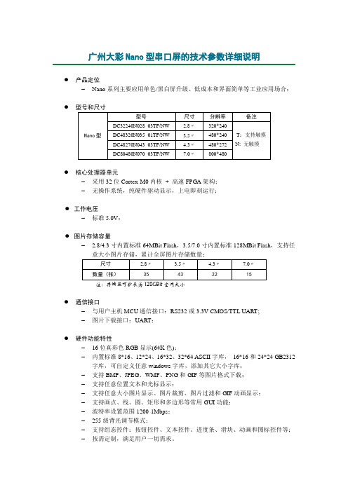
广州大彩Nano型串口屏的技术参数详细说明●产品定位– Nano系列主要应用单色/黑白屏升级、低成本和界面简单等工业应用场合;●●核心处理器单元– 采用32位Cortex-M0内核+ 高速FPGA架构;– 无操作系统,纯硬件驱动显示,上电即刻运行;●工作电压– 标准5.0V;●图片存储容量– 2.8/4.3寸内置标准64MBit Flash,3.5/7.0寸内置标准128MBit Flash,支持任意大小图片存储,累计全屏图片存储数量:●通信接口– 与用户主机MCU通信接口:RS232或3.3V CMOS/TTL UART;– 图片下载接口:UART;●硬件功能特性– 16位真彩色RGB显示(64K色);– 内置标准8*16、12*24、16*32、32*64 ASCII字库,16*16和24*24 GB2312字库,可自定义任意windows字库,添加其它大小字库;– 支持BMP、JPEG、WMF、PNG和GIF等图片格式下载;– 支持任意位置文本和光标显示;– 支持任意大小图片显示、图片裁剪、图片过滤和GIF动画显示;– 支持画点、线、圆、矩形和多边形等常用GUI功能;– 波特率设置范围1200-1Mbps;– 255级背光调节模式;– 支持组态控件:按钮控件、文本控件、进度条、滑块、动画和图标控件等;– 按需定制,满足用户一切需求。
●●LCD特性– 显示器类型:TFT LCD– 背光灯管:LED– 背光灯寿命(平均):大于30,000小时– 对比度/亮度/视角:(选用常规参数、与屏级别相关)–●触摸屏特性– 触控类型:4线精密电阻式– 触控方式:连续式– 透光率: 80%– 触控次数:>80万次– 工作温度:-20℃~70℃(与触摸板类型有关)●环境规格– 工作温度:-20℃~70℃(与液晶屏类型有关)– 相对湿度:10%-90%@40℃,无凝露– 震动测试:10 to 25Hz(X,Y,Z方向2G 30分钟)– ESD标准:Air= ±8KV,Contact= ±4KV,class B (该参数与屏类型有关)– 上电即运行,满足复杂恶劣环境,365*24*7小时不断电稳定工作●定制服务– 可定制RS485、WIFI、Zigbee或以太网等通信接口;– 定制PCB尺寸及厚度、添加用户电路、选用指定高亮度、特殊规格TFT屏;– 根据用户需要定制特殊指令或控件,降低主机开销;– 可定制电阻或电容触摸板;– 可提供图片美工及产品结构设计服务;– 一次性下单500PCS可免费进行定制,包含用户程序、PCB贴标等;– 按需定制,满足用户一切需求;●机械尺寸图各尺寸型号机械尺寸图如下所示。
NanoString数字基因定量技术原理及应用简介
NanoString数字基因定量技术原理及应⽤简介作者:胡东王芳周围段家玺范灵灵黄⼠昂导读数字化基因分析系统是最新的多重基因定量检测技术。
此技术可直接检测条形码探针标记的单个mRNA转录⼦,并通过数字计数进⾏定量;它仅需NanoString数字化基因分析系统是最新的多重基因定量检测技术。
100 ng的RNA即可对逾⼋百个特异的mRNA转录⼦进⾏准确的定量;它⽆需酶促和扩增过程,其检测的敏感性和准确性与实时荧光定量PCR(RQ—PCR)技术相当。
近年来,NanoStfing技术的特点及优势使其被越来越⼴泛地应⽤到⽣物医学前沿领域,包括⾼通量基因表达结果验证、基因表达谱研究、基因调控⽹络研究、临床疾病分⼦分型及诊断预后等领域。
随着后基因组学和系统⽣物学的发展,在特定⽣物学过程或疾病状态中对转录⽔平RNA表达的⾼通量研究越来越受到关注,并成为⼈们深⼊了解⽣物学过程中转录调控、信号转导机制、疾病分⼦病理分型等的重要⼯具。
基因芯⽚、RNA测序等技术应⽤于⾼通量基因表达谱研究,产⽣了⼤量基于各种⽣物过程及疾病模型的信息;但由于其检测敏感性和准确性不⾜,往往需要对结果中⼤量的信息进⾏进⼀步的筛选和验证。
传统的实时荧光定量PCR(real—time quantitative PCR,RQ.PCR)⽅法敏感性⾼,准确性好,是⾼通量研究最常⽤的验证⽅法;但其通量不⾜,在需要对多个基因定量的情况下,实验设计及操作步骤繁琐。
NanoString数字化基因检测技术(NanoString nCounter Analysis)是新⼀代的多重核酸定量技术,在基因表达谱的验证、研究和临床应⽤中扮演了越来越重要的⾓⾊。
NanoString技术在⼀个体系中可进⾏逾⼋百个的颜⾊条码探针和特异性序列的杂交反应,最后直接以数字化输出的形式读取定量结果。
此技术⾃动化程度⾼,反应中⽆需酶逆转及扩增的过程,避免了相关偏差,其检测敏感性、准确性和实时荧光定量PCR技术相当。
标准nano
标准nano
首先,标准nano的制定需要考虑到纳米材料的特殊性。
由于纳米材料的尺寸非常小,其性能可能会受到微观结构的影响。
因此,在制定标准时需要充分考虑纳米材料的微观结构特征,以确保标准能够准确地描述纳米材料的性能和品质。
其次,标准nano的制定还需要考虑到纳米材料的应用领域。
不同领域对纳米材料的要求可能会有所不同,因此需要针对不同的应用领域制定相应的标准。
例如,在生物医学领域,对纳米材料的生物相容性和生物安全性要求非常严格,因此需要制定相应的标准来确保纳米材料在生物体内的安全性。
另外,标准nano的制定还需要考虑到纳米材料的生产和加工过程。
纳米材料的生产和加工过程可能会对其性能和品质产生影响,因此需要制定相应的标准来规范纳米材料的生产和加工过程,以确保纳米材料的性能和品质符合要求。
总之,标准nano的制定是一个复杂而严谨的过程,需要充分考虑纳米材料的特殊性、应用领域和生产加工过程,以确保纳米材料
的性能和品质符合特定的要求。
只有通过制定科学严谨的标准,才能推动纳米材料的应用和发展,为人类社会的进步做出贡献。
纳米二氧化硅复合寒冷对A549细胞毒性及其炎性因子分泌的影响
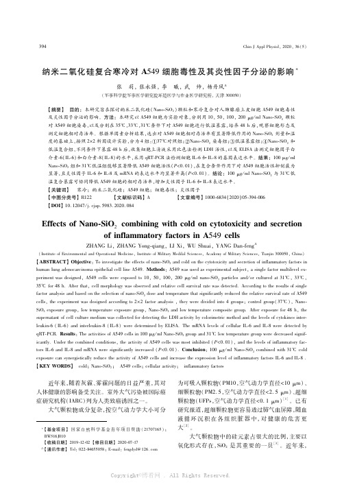
ChinJApplPhysiol,2020,36(5)
纳米氧化硅复合寒冷对 A549细胞毒性及其炎性因子分泌的影响
张 莉,张永强,李 曦,武 帅,杨丹凤
(军事科学院军事医学研究院环境医学与作业医学研究所,天津 300050)
【摘要】 目的:本研究旨在探讨纳米二氧化硅(NanoSiO2)颗粒和寒冷复合对人肺腺癌上皮细胞 A549细胞毒性 及炎性因子分泌的影响。方法:本研究以 A549细胞为实验对象,分别用 10,50,100,200μg/mlNanoSiO2 颗粒 对 A549细胞染毒,以及分别在 35℃,33℃,31℃条件下对 A549细胞进行低温暴露,培养 48h后,观察细胞形态及 测定细胞相对存活率。根据单因素分析结果,选出对 A549细胞相对存活率有显著降低作用的 NanoSiO2剂量和温 度的基础上,按照 2×2析因设计实验,分为 4组:①37℃对照组;②NanoSiO2染毒组;③低温暴露组;④NanoSiO2和 低温复合组,不同条件下暴露 48h后,收集细胞上清液采用比色法检测 LDH活性,以及 ELISA法测定细胞因子白 介素6(IL6)和白介素8(IL8)的水平,采用 qRTPCR法检测细胞 IL6和 IL8的基因表达水平。结果:100μg/ml NanoSiO2组和 31℃低温组能够显著降低 A549细胞活性(P<0.01),在复合条件作用下对 A549细胞活性抑制最为 显著,且炎性因子 IL6和 IL8及 mRNA的表达水平均显著升高(P<0.01)。结论:100μg/mlNanoSiO2与 31℃低 温复合暴露可协同降低 A549细胞的相对存活率,增加炎性因子 IL6和 IL8表达水平。 【关键词】 寒冷;纳米二氧化硅;A549细胞;细胞毒性;炎性因子 【中图分类号】R122 【文献标识码】A 【文章编号】10006834(2020)05394006 【DOI】10.12047/j.cjap.5983.2020.084
CM4 Nano V1.0 电子发展加速器用户手册说明书
CM4NANO用户手册上海晶珩电子科技有限公司2023-01-04版权声明CM4 Nano及其相关知识产权为上海晶珩电子科技有限公司所有。
上海晶珩电子科技有限公司拥有本文件的版权并保留所有权利。
未经上海晶珩电子科技有限公司的书面许可,不得以任何方式和形式修改、分发或复制本文件的任何部分。
免责声明上海晶珩电子科技有限公司不保证本硬件手册中的信息是最新的、正确的、完整的或高质量的。
上海晶珩电子科技有限公司也不对这些信息的进一步使用作出保证。
如果由于使用或不使用本硬件手册中的信息,或由于使用错误或不完整的信息而造成的物质或非物质相关损失,只要没有证明是上海晶珩电子科技有限公司的故意或过失,就可以免除对上海晶珩电子科技有限公司的责任索赔。
上海晶珩电子科技有限公司明确保留对本硬件手册的内容或部分内容进行修改或补充的权利,无需特别通知。
修订记录目录1产品概述 (6)1.1目标应用 (6)1.2规格参数 (6)1.3系统框图 (7)1.4功能布局 (8)1.5包装清单 (8)1.6订购编码 (8)2快速启动 (9)2.1设备清单 (9)2.2硬件连接 (9)2.3首次启动 (9)2.3.1Raspberry Pi OS (Desktop) (9)2.3.2Raspberry Pi OS (Lite) (12)2.3.3使能SSH功能 (14)2.3.4查找设备IP (14)3接线指南 (14)3.1Panel I/O (15)3.1.1BOOT (15)3.1.2micro-SD Card (15)3.2Internal I/O (15)3.2.1HDMI FPC (15)3.2.2MIPI DSI (16)4软件操作指引 (17)4.1USB 2.0 (17)4.1.1查看USB设备信息 (17)4.1.2USB存储设备挂载 (17)4.2以太网配置 (19)4.2.1千兆以太网 (19)4.2.2使用Network Manager工具配置 (19)4.2.3使用dhcpcd工具配置 (21)4.3WiFi (21)4.3.1使能WiFi功能 (21)4.3.2外置天线/内置PCB天线 (22)4.3.3AP及桥接模式 (22)4.4蓝牙 (22)4.4.1基本用法 (22)4.4.2示例 (23)4.5RTC (24)4.6LED指示 (25)4.7Buzzer (25)4.8串口通信 (25)4.8.1安装picocom工具 (25)4.8.2Debug UART (26)5操作系统安装 (27)5.1镜像下载 (27)5.2eMMC烧录 (28)5.2.1工具下载 (28)5.2.2烧录 (28)5.3基于原版Raspberry Pi OS在线安装BSP (29)6故障排除 (29)7FAQ (29)7.1.1默认用户名密码 (29)8关于我们 (30)8.1关于EDATEC (30)8.2联系方式 (30)1CM4 Nano是一款基于树莓派CM4的面向工业应用场景的计算机。
纳米银溶液的质量标准
读数比值的平均值为纵坐标(Y),相应浓度(X)为横坐标,作标 准曲线,得 Y=0.16X-0.12(r=0.999 2)。结果,银的检测浓度 线性范围为 2~10 μg·mL-1。 2.4.5 精密度试验。精密吸取银标准液,连续测定 5 次,测定 结果的 RSD=0.6%(n=5),说明仪器性能良好。 2.4.6 回收率试验。取已知银含量的纳米银溶液适量,共 9 份,分别定量加入银标准液适量,按“2.4.3”项下供试品液的制 备方法制样,测定其中银的含量,计算回收率,结果见表 1。
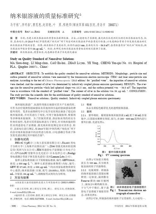
ABSTRACT OBJECTIVE:To establish the quality standard for nanosilver solutions. METHODS:Morphology,particle size and surface potential of nanosilver solution were measured by the transmission electron microscope(TEM)and laser nano-particle size analyzer. According to the test of Chinese Pharmacopoeia(2010 edition)for“purified water”,the impurities of nanosilver solution were checked. And the content of silver was determined by inductively coupled plasma emission spectrometry. RESULTS:The average size for nanosilver particles which had spherical shape was 15.24 nm,and the surface potential was -36.5 mV. The impurities were in accordance with the standard of“purified water”. The content of silver in the solution was 86 μg·mL-1. CONCLUSION: The study provides the scientific data for the establishment of quality standard of nanosilver solutions. KEY WORDS Nanosilver solutions;Quality standard;Inductively coupled plasma emission spectrometry
- 1、下载文档前请自行甄别文档内容的完整性,平台不提供额外的编辑、内容补充、找答案等附加服务。
- 2、"仅部分预览"的文档,不可在线预览部分如存在完整性等问题,可反馈申请退款(可完整预览的文档不适用该条件!)。
- 3、如文档侵犯您的权益,请联系客服反馈,我们会尽快为您处理(人工客服工作时间:9:00-18:30)。
柱状胶团:随胶团表面曲率的减小,胶团增大,减小端 基面积,胶团增大 三种形成柱状胶团的方法: (1)加入具有较小端基的助表面活性剂,如醇羟基相对于 带电荷的磺酸根来说较小 (2)改变反电荷离子,如将Na+改为Mg2+会减小端基的有 效体积 (3)通过电解质的加入或温度的改变而改变非离子型端基 的亲水性
球形胶团:通常是在阴离子表面活性剂存在下或同时 存在其它表面活性剂的条件下形成。
对于油/水胶团,可以通过调节相邻端基间的排斥力, 使a0较大,而胶团半径与表面活性剂分子的最大拉伸 长度近似相等,聚集体较小
反胶团:分散相为水、分散介质为油时,表面活性剂 亲水基团朝里面,疏水基团朝外面,所形成的胶团称 为反胶团。 反胶团是由表面活性剂分子的逐级缔合形成的,即单 体→二聚体→三聚体→多聚体,因此其聚集数小,无 明显的临界胶团浓度,胶团大小分布宽 形成反胶团常用的有机溶剂为6-8个碳原子的链烷烃或 环烷烃
(2)金属硫化物纳米粒子的制备
利用微乳液中的沉淀法:两种反胶团中一种溶解有Cd2+, Pb2+, Cu2+, Ag+等金属离子,另一种溶有S2- (一般来源于Na2S 或 H2S),混合时,即形成CdS, PdS等半导体纳米粒子
Me2+ + S2- → MeS↓ CdS, PbS, Cu2S, CuS, Ag2S, MoS3, CdSe等
胶团与反胶团 胶团:当液相中表面活性剂的浓度超过其临界胶团浓度 时所形成的表面活性剂聚集体,而反胶团不一定有临界 胶团浓度。 当表面活性剂浓度超过其临界浓度时,多出的表面活 性剂以聚集体或胶团的形式存在,其性质发生变化,如 渗透压、混乱度、溶解性、表面张力、传导等,开始胶 团为球形,当表面活性剂浓度进一步增大时,胶团被破 坏并改变形状,如棒状胶团、六方胶团、层状胶团或液 晶等
2. 微乳液的性质和特点: 微乳液的性质和特点:
微乳液定义:由水、油、表面活性剂、助表面活性剂自发 形成的含有球形或柱状的8-100nm的胶体粒子的透明或半 透明的热力学稳定的分散体系,微观上是由表面活性剂界 面膜所稳定的一种或两种液体的微滴所构成。 微乳液组成:水、油、表面活性剂、助表面活性剂(通常是 中等长度的脂肪醇,如C6-C8的脂肪醇) 分散相:10~100nm的小液滴 分散相为油、分散介质为水:油/水微乳液(O/W) 反之,水/油微乳液(W/O) 微乳液与普通乳状液的根本区别:自发形成、热力学稳定
对于需要酸碱催化才能水解的醇盐如Si(OC2H5)4,可以用氨水 代替水,而对于Zr(OC4H9)4则可以通过在聚氧乙烯基壬基苯基 醚/环己烷体系中用硫酸溶液水解 目前,通过沉淀、加热法获得的氧化物纳米粒子包括MFe2O4, YBa2Cu3O7-δ, Al2O3, LaMnO3, BaFe12O19, Cu2L2O7 (L=Ho, Er), LiNi0.8Co0.2O2等 通过醇盐水解合成的氧化物纳米粒子包括:ZrO2, TiO2, SiO2, GeO2, γ-Fe2O3等 一般来说,醇盐水解获得的纳米粒子分散性及粒度分布较好
胶团的形成
从界面上表面活性剂的几何因素确定胶团形状 端基面积:a0,烷基链体积:V,最大长度:lc 遵守以下规则: 球形:V/a0lc < 1/3 非球形(如柱状胶团):1/3 < V/a0lc <1/2 囊泡或双层胶团:1/2 < V/a0lc <1 反胶团: 1< V/a0lc 但环境变化会对参数有影响,从而影响界面上的分子 排列
(4) 金属盐纳米粒子 )
具有优异性能的卤化银、金属硫酸盐、金属碳酸盐的合成 通常通过微乳液中的沉淀法来合成 如:在AOT/水/油微乳液中,以AgNO3和卤化钠作原料,制 备卤化银纳米粒子 Ag+ + X- → AgX↓ ↓ 对于金属碳酸盐的合成,可以通过向含有相应金属氢氧化物 或金属离子的反胶团溶液中通入CO2气体合成 如:在六甘醇(HOCH2(CH2OCH2)5CH2OH)/水/环己烷体系中, Ca(AOT)作为Ca源,通入CO2气体形成平均粒径为5.4nm 的 CaCO3纳米粒子
v: 表面活性剂中烷基链的体积 a0: 表面活性剂中极性头的最佳截面积 lc: 烷基链的长度
自发形成,制备方便 热力学稳定,可长期保存而不会油水分离 胶粒细小均匀,界面面积大,可加速表面反应 低界面张力,使其易变形、具有高渗透能 低黏度,易传输与混合 对油水均有很大的相互增溶作用,使其具有亲油、亲 水两重性 O/W型微乳液需要较少的助表面活性剂 助表面活性剂能够降低界面张力,大量时可改善界面 的曲率,有利于形成W/O型微乳液 表面活性剂的性质是影响微乳液类型的重要因素
普通乳状液、微乳液和胶团溶液的性质比较
普通乳状液 微乳液 外观 质点大小 性 质点形状 不透明 胶团溶液 透明或近透明 一般透明
大于100nm, 10-100nm, 单 小于100nm 多分散体系 分散体系 一般为球形 球形 稀溶液中为球形,浓 溶液中可呈各种形状
质 热力学稳定性 不稳定,用 稳定,用离心 稳定,不分层 离心机易于 机不能分离 分离 表面活性剂用 少,一般无 多,一般需助 浓度大于cmc即可,增 量 需助表剂 表剂 溶量大时可适当多加 与油水混溶性 O/W型与水 与油水在一定 可增溶油或水直达饱 混溶,W/O 范围内可混溶 和 型与油混溶
(1)金属纳米材料的还原合成 利用反胶团微乳液制备金属纳米粒子 两种反胶团溶液分别含有溶解的金属盐和合适的还原 剂,混合后,金属离子被还原为金属 大部分金属的还原是直接进行的 所制备金属的种类受到体系的限制 所制备纳米粒子:表面覆盖一层表面活性剂,阻止了 粒子的团聚,粒子表面易被进一步修饰,粒度分布窄
第三节 微乳液法
1. 研究背景及进展
早期人们认为油水不能完全混溶,但可以形成不透明的乳 状分散液 1928年美国化学工程师 Rodawald在研制皮革上光剂时意 外得到了“透明乳状液” 1943年Hoar和Schulman证明了这是由大小为8-80nm的球 形或圆柱状颗粒构成的分散体系 1958年Schulman给它命名为微乳液(microemulsion),意思 是微小颗粒的乳状液 60-90年代,微乳液在理论方面得到进一步的发展 90年代以来微乳液的应用研究得到快速发展
对于离子型表面活性剂,反离子一般为一价,临界胶团浓度 较大,一般为1-20mmol/L。将单价离子用多价离子取代,可 使临界胶团浓度明显降低。其胶团的聚集数一般为50-60, 当浓度不超过很多时,一般为球形胶团,当超过十倍以上时 将不再是球形。
对于非离子表面活性剂,临界胶团浓度取决于分子结构, 其值较小,一般为0.04-3mmol/L。由于极性基团间不存在 离子性电荷的斥力,所以聚集数一般较大,在100以上
(5) 复合纳米粒子
三明治型、核壳结构 典型的为半导体复合纳米粒子的制备 如已合成的三明治型CdS-TiO2, CdS-SnO2复合纳米粒子材料 在太阳能电池方面表现出应用前景 核壳纳米粒子:CdS-ZnS, CdS-PbS, CdS-HgS, CdS-CdSe, CdSe-ZnS, CdSe-ZnSe等表现出优异的光催化和发光性能
5. 微乳液的制备
Schulman法 油、水、表面活性剂 Shah法 油、醇、表面活性剂
滴加醇
滴加水
相图对微乳液的制备具有指导作用
6. 微乳液的应用
三次采油中的应用 萃取中的应用 洗涤过程中的应用 药剂和化妆品中的应用 化学反应方面的应用——合成新材料
微乳液在纳米材料合成中的应用
纳米粒子的制备主要集中于反胶团微乳液中,主要包 括三种过程: 沉淀——通常用于金属硫化物、金属氧化物、金属碳 酸盐、卤化银纳米粒子的制备; 还原——主要用于金属纳米粒子的制备; 水解——主要用于金属氧化物的制备
增溶现象具有多种应用 如不溶性药物的增溶——用于静脉注射 胶团体系的增溶——用于去污 可能的增溶嵌入方式: 在胶团的碳氢核中 在胶团中定向排列 在表面活性剂的亲水部分(如非离子表面活性剂的乙烯 氧基) 吸附于胶团表面
1974年,Shinoda 等提出了微乳液理论,将微乳液看作 水-表面活性剂-助表面活性剂的三组分溶液体系 其中位于相图顶端(油)的一相可溶解大量水 位于相图左下方(水)的一相可溶解大量油
3. 微乳液的形成机理 负界面张力理论(Schulman and Price)
瞬间负界面张力是形成微乳液的主要原因
增加另一种可吸附在界面上的组分可使界面张力进一 步降低,利于微乳液的形成
溶胀的胶团理论
微乳液在很多方面类似于胶团溶液
胶团向微乳液转变过程中,许多物理性质无明显变化 因此增溶作用是微乳液自发形成的原因之一
增溶作用和微乳液的形成
一、增溶作用:在包含表面活性剂体系中,某些情况下 疏水(亲水)物质在水(油)中的溶解远远超过了它 们在水(油)中的一般溶解度 由于胶团内部提供了疏水(亲水)的环境,在其中可 容纳非极性(极性)化合物,当表面活性剂浓度达到 临界胶团浓度时,疏水(亲水)物质的溶解性随表面 活性剂浓度的增大而急剧增大
如:利用Cd(AOT)2作为表面活性剂和原料,在AOT或三硝基 甲苯反胶团中合成CdS纳米粒子 其中可通过调节Cd2+和S2-的相对含量控制CdS纳米粒子粒径 AOT:二(2-乙基己基)磺化琥珀酸钠
(3) 金属氧化物纳米粒子的制备 ) a. 类似于水溶液中氧化物的合成:首先加入碱使反胶团中的金
属离子沉淀,然后分离、加热脱水、晶化 氧气氛中加Байду номын сангаас 如:M2+ + 2Fe2+ + OH-(过量) —————→ MFe2O4 + xH2O b. 主要通过金属醇盐与反胶团中的水发生水解反应而形成 如:Ti(OiPr)4 + 2H2O → TiO2 + 4(iPr-OH) 首先将Ti(OiPr)4 溶于无水的反胶团中,然后加入含水的反胶 团溶液 也可将醇盐溶于有机溶剂,然后加入含水反胶团溶液形成氧 化物纳米粒子 如:向AOT/环己烷的水/油微乳液中加入Ge(OC2H5)4的无水环 己烷溶液,可水解形成GeO2 纳米粒子