CO2-fuel 光催化反应-掺碘TIO2
光催化co2 ch4 tio2
光催化CO2 CH4 TiO2光催化是一种通过光能激发催化剂表面的化学反应的方法。
在这个过程中,光能会激发催化剂表面的电子,从而导致化学反应的发生。
CO2和CH4是两种常见的温室气体,它们对全球气候变化产生了重要影响。
TiO2是一种著名的光催化剂,它在光催化CO2和CH4方面显示出了很大的潜力。
1. 光催化CO2CO2是一种重要的温室气体,它对全球气候变化产生了重要影响。
开发出一种有效的方法来减少大气中CO2的含量对于应对气候变化问题非常重要。
光催化CO2就是一种很有潜力的技术。
TiO2作为光催化剂,在光照条件下能够将CO2转化为有用的化合物,如甲烷或一氧化碳。
这种转化过程不仅可以减少大气中的CO2含量,还可以产生有用的燃料或化学品。
2. 光催化CH4CH4是另一种重要的温室气体,它的温室效应比CO2还要强烈。
减少大气中CH4的含量同样是一个重要的问题。
TiO2在光催化CH4方面也显示出了很大的潜力。
在光照条件下,TiO2可以催化CH4的氧化反应,将其转化为CO2和水。
这样的反应能够有效地减少大气中CH4的含量,有助于缓解温室效应。
3. TiO2的优势TiO2作为一种光催化剂,具有很多优势。
它是一种相对廉价的材料,容易获取和制备。
TiO2对于光的吸收能力很强,可以有效地转化光能为化学反应的能量。
TiO2在化学稳定性和光化学稳定性方面也表现出了很好的性能,能够长时间稳定地进行光催化反应。
4. 个人观点在我看来,光催化CO2和CH4是一种非常有前景的技术。
这种技术不仅可以帮助我们应对气候变化问题,还可以为可持续能源和化工领域提供重要的支持。
TiO2作为一种光催化剂,在这个领域显示出了很大的潜力。
未来,我希望能看到更多的研究能够进一步发展和应用光催化CO2和CH4技术,为我们创造一个更加清洁和可持续的未来。
总结:通过光催化CO2和CH4,TiO2可以成为一种重要的解决方案,帮助人类应对气候变化问题。
光催化技术的发展不仅对环境保护具有重要意义,也为可持续能源和化工领域提供了新的可能性。
tio2光催化氧化技术
tio2光催化氧化技术文章标题:TIO2光催化氧化技术:从原理到应用的逐步解析引言:TIO2光催化氧化技术是一种通过利用钛白粉(TiO2)在紫外光照射下产生的催化作用来降解及去除有害物质的环境治理技术。
该技术具有高效、无污染、自洁性等优点,因而在空气净化、水处理、有机废弃物处理等领域展现出广阔的应用前景。
本文将从原理、催化剂的制备、反应条件的优化以及应用领域四个方面逐步解析TIO2光催化氧化技术的实施过程。
第一部分:原理的解析TIO2光催化氧化技术的核心原理是光催化效应。
当钛白粉受到紫外光照射时,导带上的电子被激发到价带上,形成电子空穴对。
电子空穴对之间的迁移与它们与溶液中有机污染物之间的氧化反应同时发生。
TIO2表面吸附的有机污染物在电子空穴对的作用下,经历一连串的氧化反应,最终转化为无害的物质。
催化剂的选择和制备工艺是实现高效光催化氧化的关键。
第二部分:催化剂的制备催化剂的制备包括物理法、化学法和物理化学方法。
物理法主要是利用物理能量引起物料结构的改变,如溅射法等;化学法通常是通过溶液反应合成催化剂,如溶胶-凝胶法、水热法等;而物理化学方法则是将物理和化学方法结合使用,如浸渍法、气相法等。
不同的制备方法将导致催化剂的物理和化学性质产生差异,进而影响催化效果。
第三部分:反应条件的优化反应条件的优化在TIO2光催化氧化技术中至关重要。
反应条件包括溶液pH值、催化剂浓度、反应温度、光照强度等。
适当调节反应条件可以提高光催化效果。
例如,适当增加溶液pH值有助于提高催化效果,而过高的催化剂浓度可能导致催化剂之间的覆盖效应,从而减缓反应速率。
反应温度的升高可以加快有机废物的降解速度,但过高的温度可能对催化剂的稳定性产生不利影响。
第四部分:应用领域的探索TIO2光催化氧化技术在空气净化、水处理以及有机废弃物处理等领域均有广泛应用。
在空气净化方面,TIO2催化剂可用于去除大气中的有机污染物和臭氧;在水处理方面,通过TIO2光催化氧化技术可以降解废水中的有机物、重金属离子等;在有机废弃物处理方面,利用TIO2光催化氧化技术可以有效降解有害物质。
TiO2光催化反应及其在废水处理中的应用

TiO2光催化反应及其在废水处理中的应用随着人口的增加和工业化的快速发展,水资源的污染问题日益突出,给环境和人类健康带来了巨大威胁。
因此,寻找高效、低成本的废水处理技术变得尤为重要。
TiO2光催化反应由于其高效、环境友好的特点,在废水处理中得到了广泛应用。
TiO2是一种常见的金属氧化物,具有良好的稳定性、耐腐蚀性和光催化性能。
光催化反应是指在光照下,光催化剂吸收光能产生活性氧物种,通过氧化还原反应将有机污染物转化为无害的物质。
TiO2光催化反应的原理主要基于其能带结构和表面活性位点。
当光照入射到TiO2表面时,激活光子会激发电子从价带跃迁到导带,产生电子-空穴对。
电子和空穴在晶体内部进行迁移,发生氧化还原反应。
此外,TiO2表面的羟基(OH)和缺陷位点也可以吸附有机污染物,提高催化剂的活性。
尽管TiO2光催化反应具有良好的光催化性能,但纯TiO2的光响应范围较窄,主要在紫外线(UV)区域。
为了拓展其光响应范围,研究者们通过掺杂、复合和修饰等方法进行了改性。
掺杂将其他金属或非金属元素引入TiO2晶格中,改变了其能带结构和吸收光谱。
复合将TiO2与其他材料进行复合,形成新的光催化剂。
修饰利用纳米材料对TiO2进行修饰,增强了其光催化性能。
这些方法不仅提高了光催化剂的光响应范围,还改善了其光催化效率。
在废水处理中,TiO2光催化反应被广泛应用于去除有机物、重金属离子和细菌等污染物。
有机污染物是废水中主要的污染源之一,包括有机溶剂、农药、染料和药物等。
这些物质具有难降解性和毒性,传统的废水处理方法往往效果不佳。
而TiO2光催化反应能够将有机污染物降解为无害的物质,大大提高了废水处理的效果。
重金属离子是废水中另一个常见的污染物,具有持久性和生物蓄积性。
TiO2光催化反应能够将重金属离子还原为金属,或通过与金属形成络合物沉淀,有效去除废水中的重金属污染物。
此外,TiO2光催化剂还可以发生光生杀菌作用,通过破坏细菌细胞结构和代谢功能来净化废水。
以二氧化钛为催化剂的光热化学循环分解二氧化碳反应

二氧化碳是地球大气中的一种重要气体,但其过多的排放与全球变暖、气候变化密切相关。
寻找有效的方法降低二氧化碳的排放量,控制温室效应,已成为当今世界各国共同关注的环境问题。
在这一背景下,利用太阳能光热化学循环分解二氧化碳成为了一种备受关注的研究方向。
这种通过太阳能驱动的过程可以将大气中的二氧化碳转化为有用的碳氢化合物,从而实现碳的循环利用,减少对化石燃料的依赖,减少二氧化碳的排放,具有重要的环境和经济意义。
其中,二氧化钛(TiO2)作为催化剂在光热化学循环分解二氧化碳反应中扮演着关键的角色。
本文将介绍二氧化钛催化的光热化学循环分解二氧化碳反应的原理、研究进展、应用前景及存在的挑战。
一、原理光热化学循环分解二氧化碳反应是利用太阳能提供的光能和热能驱动的一种能量转化过程。
在反应中,首先利用太阳能光照的作用下,催化剂二氧化钛吸收光子,产生对电子-空穴对激发,然后通过光生载流子与接触的还原剂(如甲烷、一氧化碳等)发生光催化反应还原二氧化碳,生成一氧化碳、甲烷等碳氢化合物。
随后,通过提高反应温度,可实现二氧化碳还原生成碳氢化合物的热催化反应。
整个过程中,二氧化钛催化剂的表面电子转移和活性位点的设计对反应效率起着至关重要的作用。
二、研究进展近年来,国内外学术界对以二氧化钛为催化剂的光热化学循环分解二氧化碳反应展开了广泛而深入的研究。
研究发现,通过控制二氧化钛的晶体结构、表面形貌及掺杂能够有效提高催化剂的光催化和热催化活性。
也有学者通过复合材料构建、表面修饰和负载合金纳米颗粒等方法优化了二氧化钛催化剂的性能。
这些探索不仅丰富了对光热化学循环分解二氧化碳反应机理和催化剂表面反应过程的理解,同时为二氧化碳资源化利用提供了实验和理论依据。
以二氧化钛为催化剂的光热化学循环分解二氧化碳反应已被应用于光催化还原二氧化碳产甲烷、制备CO、CH4和C2H5OH等碳氢化合物等领域,初步显示出了广阔的应用前景。
三、应用前景以二氧化钛为催化剂的光热化学循环分解二氧化碳反应具有重要的应用前景。
二氧化钛光催化原理
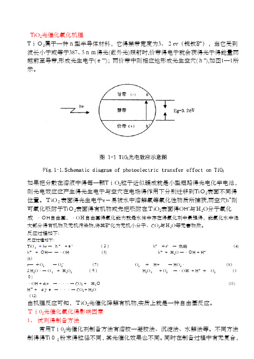
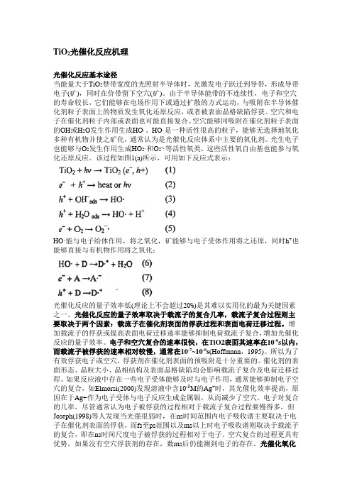
TiO 2光催化氧化机理T iO2属于一种n型半导体材料,它得禁带宽度为3、2ev (锐钛矿),当它受到波长小于或等于387、5nm得光(紫外光)照射时,价带得电子就会获得光子得能量而越前至导带,形成光生电子(e—);而价带中则相应地形成光生空穴(h+),如图1—1所示。
如果把分散在溶液中得每一颗T iO 2粒子近似瞧成就是小型短路得光电化学电池,则光电效应应产生得光生电子与空穴在电场得作用下分别迁移到Ti O2表面不同得位置。
TiO 2表面得光生电子e -易被水中溶解氧等氧化性物质所捕获,而空穴h +则可氧化吸附于Ti O2表面得有机物或先把吸附在TiO 2表面得OH -与H2O 分子氧化成 ·OH 自由基,·O H自由基得氧化能力就是水体中存在得氧化剂中最强得,能氧化水中绝大部分得有机物及无机污染物,将其矿化为无机小分子、CO 2与H2O 等无害物质。
反应过程如下:反应过程如下:TiO 2 + hv → h+ +e- (3) h + +e - → 热能 (4) h + + OH — →·OH (5) h + + H2O →·OH + H + (6)e — +O 2 → O 2- (7) O 2 + H+ → HO 2· (8) 2 H 2O ·→ O 2 + H2O 2 (9) H 2O 2 + O 2 →·O H + H + + O 2 (10)·OH + dye →···→ CO 2 + H2O (11) H + + d ye →···→ CO 2 + H 2O (12)由机理反应可知,TiO 2光催化降解有机物,实质上就是一种自由基反应。
Ti02光催化氧化得影响因素1、 试剂得制备方法常用T i02光催化剂制备方法有溶胶一凝胶法、沉淀法、水解法等。
TiO2光催化原理和应用
TiO2光催化原理及应用一、前言在世界人口持续增加以及广泛工业化得过程中,饮用水源得污染问题日趋严重。
根据世界卫生组织得估计,地球上22%得居民日常生活中得饮用水不符合世界卫生组织建议得饮用水标准.长期摄入不干净饮用水将会对人得身体健康造成严重危害,世界范围内每年大概有200 万人由于水传播疾病死亡.水中得污染物呈现出多样化得趋势,常见得污染物包括有毒重金属、自然毒素、药物、有机污染物等。
常规得饮用水净化技术有氯气、臭氧与紫外线消毒以及过滤、吸附、静置等,但就是这些方法对新生得污物往往不就是非常有效,并且可能导致二次污染.包括我国在内世界范围内广泛应用得氯气消毒法,可能在水中生成对人类健康有害得高氯酸盐。
臭氧消毒就是比较安全得消毒方法,但就是所需设备昂贵;而紫外线消毒法需要能源支持,并且日常得维护都需要专业得技术人员;吸附法一般需要消耗大量得吸附剂,使用过得吸附剂一般需要额外得处理。
这些缺点限制了它们得应用范围,迫切需要发展一种高效、绿色、简单得净化水技术。
自然界中,植物、藻类与某些细菌能在太阳光得照射下,利用光合色素将二氧化碳(或硫化氧)与水转化为有机物,并释放出氧气(或氢气)。
这种光合作用就是一系列复杂代谢反应得总与,就是生物界赖以生存得基础,也就是地球碳氧循环得重要媒介。
光化学反应得过程与植物得光合作用很相似。
光化学反应一般可以分为直接光解与间接光解两类.直接光解为物质吸收能量达到激发态,吸收得能量使反应物得电子在轨道间得转移,当强度够大时,可造成化学键得断裂,产生其它物质。
直接光解就是光化学反应中最简单得形式,但这类反应产率一般较低。
间接光解则为反应系统中某一物质吸收光能后,再诱使另一种物质发生化学反应。
半导体在光得照射下,能将光能转化为化学能,促使化合物得合成或使化合物(有机物、无机物)分解得过程称之为半导体光催化。
半导体光催化就是光化学反应得一个前沿研究领域,它能使许多通常情况下难以实现或不可能进行得反应在比较温与得条件下顺利进行。
光催化co2还原产碳氢产物
光催化co2还原产碳氢产物光催化CO2还原产碳氢产物光催化CO2还原是一种可持续的方法,可以利用太阳能将二氧化碳转化为有用的碳氢化合物。
这一过程不仅可以减少温室气体的排放,还可同时产生有价值的化学品,具有重要的环境和经济意义。
在光催化CO2还原的过程中,光催化剂起着至关重要的作用。
光催化剂可以吸收太阳能并将其转化为化学能,从而促使二氧化碳的还原反应发生。
其中,一种常用的光催化剂是二氧化钛(TiO2)。
二氧化钛具有良好的光催化性能,能够有效地促进CO2的还原反应。
当太阳光照射到光催化剂表面时,光子的能量被吸收并激发了光催化剂中的电子。
这些激发的电子可以迁移到催化剂表面,并与CO2分子发生反应。
在光催化剂的作用下,二氧化碳分子被还原为碳氢化合物,如甲烷(CH4)或乙烷(C2H6)。
光催化CO2还原的过程中,还需要合适的催化剂和反应条件。
催化剂的选择要考虑到其光催化性能、稳定性和成本等因素。
此外,反应条件如温度、压力和反应时间等也会对还原反应的产物选择和产率产生影响。
光催化CO2还原产碳氢产物的研究已经取得了一定的进展。
许多研究人员通过调控催化剂的晶体结构、表面形貌和组分等来提高其光催化性能。
同时,一些研究还关注了反应机理和反应动力学等方面的问题,以深入理解光催化CO2还原的本质。
尽管光催化CO2还原技术仍面临一些挑战,如低产率和选择性等问题,但它作为一种可持续的CO2减排方法具有巨大的潜力。
光催化CO2还原不仅可以通过减少CO2排放来应对气候变化,还可以为碳氢化合物的生产提供新途径,促进可持续发展。
光催化CO2还原产碳氢产物是一项前沿的研究领域,具有重要的环境和经济意义。
通过光催化技术,我们可以将二氧化碳转化为有用的碳氢化合物,实现CO2资源化利用,为可持续发展做出贡献。
希望在不久的将来,光催化CO2还原技术能够得到进一步的发展和应用,为解决气候变化和能源问题提供更多的解决方案。
TiO2光催化反应机理
TiO2光催化反应机理光催化反应基本途径当能量大于TiO2禁带宽度的光照射半导体时,光激发电子跃迁到导带,形成导带电子(矿),同时在价带留下空穴(矿)。
由于半导体能带的不连续性,电子和空穴的寿命较长,它们能够在电场作用下或通过扩散的方式运动,与吸附在半导体催化剂粒子表面上的物质发生氧化还原反应,或者被表面晶格缺陷俘获。
空穴和电子在催化剂粒子内部或表面也可能直接复合。
空穴能够同吸附在催化剂粒子表面的OH或H2O发生作用生成HO·。
HO·是一种活性很高的粒子,能够无选择地氧化多种有机物并使之矿化,通常认为是光催化反应体系中主要的氧化剂。
光生电子也能够与O2发生作用生成HO2·和O2-·等活性氧类,这些活性氧自由基也能参与氧化还原反应。
该过程如图1(a)所示,可用如下反应式表示:HO·能与电子给体作用,将之氧化,矿能够与电子受体作用将之还原,同时h+也能够直接与有机物作用将之氧化:光催化反应的量子效率低(理论上不会超过20%)是其难以实用化的最为关键因素之一。
光催化反应的量子效率取决于载流子的复合几率,载流子复合过程则主要取决于两个因素:载流子在催化剂表面的俘获过程和表面电荷迁移过程。
增加载流子的俘获或提高表面电荷迁移速率能够抑制电荷载流子复合,增加光催化反应的量子效率。
电子和空穴复合的速率很快,在TiO2表面其速率在10-9s以内,而载流子被俘获的速率相对较慢,通常在10-7~10-8s(Hoffmann,1995)。
所以为了有效俘获电子或空穴,俘获剂在催化剂表面的预吸附是十分重要的。
催化剂的表面形态、晶粒大小、晶相结构及表面晶格缺陷均会影响载流子复合及电荷迁移过程。
如果反应液中存在一些电子受体能够及时与电子作用,通常能够抑制电子空穴的复合,如Elmorsi(2000)发现溶液中含10-3M的Ag+时,其光催化效率提高,原因在于Ag+作为电子受体与电子反应生成金属银,从而减少了空穴.电子对复合的几率。
光催化还原二氧化碳为燃料:机遇和挑战

还原的有机产物重新降解生成 C O, 。截至目前 ,科学家 对产物分布上的控制因素了解甚少 ,也缺少一个如何改性 光催化剂以生成单一产物的明确思路 。科学家们正通过理 论及实验分析各种不同产物的反应途径以及在催化剂上的
种情况下 ,光催化剂必须具有足够大的 CO, 吸附能力 , 以确保足够高浓度的 C o 吸附于催化剂表 面 ,从而有效 地 促进 光 催化 还原 反应 。同时 ,尽 可能 保证 反应 介 质 中存 在高浓度 H+ ,以降低 CO, 的还原电位 。
入空 d轨道 , 从而有效减小带隙 。但是 , 对于在水中进行 反 应 的光 催 化 剂 ,金 属 掺 杂 的 T i O2 会受 到 光 腐蚀 ,导致 金属浸出和催化剂逐渐失活 。采用非金属 ( C、 N、S 、F、 CI 、l 等) 掺杂 的 方式 可 以产生 更稳 定 的 T i O, 光 催化 剂 。
催化剂上 ,这些复合催化 ̄ t l A 9 光催化活性被认为是由于金 属纳米粒子发生表面等离子共振 , 其特征吸收区为可见光 区域 ,波长从 4 5 0至 7 0 0 n m,这些 金属纳 米粒 子针对 光腐蚀的稳定性高 。贵金属纳米粒子和半导体光催化剂的
协 同 作用 在很 多方 面 使光 催化过 程 发生 显著 变化 。最显 著
物要比光解水的产物复杂得多 。这种产物选择 注的缺乏降 低了光催化还原 C O 的效率和经济性 ;另一方面 ,部分
还原产 物 可 以使光 催化 剂 中毒 ,或 者作 为半 导 体 中光 激发 分 离 的活 性 电 子 和 空 穴 的猝 灭 剂 ,甚 至 会 使光 催 化 C o,
TiO2光催化

二氧化钛(TiO)由于其优异的光电转换及物化性能成为半导体光催化材料中的2研究热点。
二氧化钛纳米晶半导体太阳能电池,是利用纳晶多孔薄膜电极,通过增大其表面积来提高电池的光电转换效率,该项技术无论在理论基础及应用技术上都有一定的发展潜力,具有取代硅太阳能电池及传统的太阳能电池发电的可能性,对TiO纳米晶半导体太阳能电池的深入研究,大大促进纳米结构半导体光2在能量大于其禁带宽度的电化学新兴学科领域的发展。
在环境污染的治理,TiO2光照射下,产生电子与空穴对,然后光生电子迁移至催化剂表面实现光生载流子的有效分离,光生空穴的强氧化能力以及导带电子的还原能力使其能有效地氧化还原大部分有机物及一些金属离子,基于这一点,在环境污染的治理方面具有重大意义,因而制备性能优良的二氧化钛光催化剂成为一项有意义的工作。
是一种价格便宜、无毒、稳定且抗腐蚀性良好的半导体材料。
但是,由于纳TiO2能带间隙较宽(锐钛矿,金红石型),对太阳光的吸收效率很低,米尺度的TiO2只能吸收太阳光中4%的紫外光部分,所以必须对其进行改性,扩宽其吸收利用的波段。
一般有以下三种方法:一是通过与能带间隙较窄的半导体复合;二是通的敏化。
过掺杂其他元素;三是利用染料进行TiO2TiO通常有三种晶型,板钛矿(brookite)在自然界中量很少而研究极少;在这三2种晶型中,锐钛矿(anatase)的催化活性最高。
锐钛矿和金红石的结构可以用一个Ti06八面体链来表示,不同之处在于二种晶型的变形程度和八面体链的连结方式不同,每个Ti4+被6个O2-包围,形成一个八面体。
金红石八面体结构并不规则,呈现轻微的正交晶系变形;锐钛矿八面体变形程度更大,因此对称性减小。
板钛矿属斜方晶系,性质不稳定,在650℃时转化成金红石结构,其应用的不是很多;锐钛矿比较稳定,在800℃时转化成金红石结构,金红石不可转化成锐钛晶体中Ti4+离子位于相邻的矿和板钛矿,金红石和锐钛矿都属于四方晶系,TiO2六个O2-离子所形成的八面体中心。
Tio2的光催化性能研究
TiO2的光催化性能研究摘要:主要介绍二氧化钛的光催化原理,基本途径,以及光催化剂的结构特性和影响因素,还讲述了关于二氧化钛的光催化应用。
关键字:二氧化钛光催化光催化剂,俗称钛白粉,多用于光触媒、化妆品,能靠紫外二氧化钛,化学式为TiO2线消毒及杀菌,现正广泛开发,将来有机会成为新工业。
二氧化钛可由金红石用酸分解提取,或由四氯化钛分解得到。
二氧化钛性质稳定,大量用作油漆中的白色颜料,它具有良好的遮盖能力,和铅白相似,但不像铅白会变黑;它又具有锌白一样的持久性。
二氧化钛还用作搪瓷的消光剂,可以产生一种很光亮的、硬而耐酸的搪瓷釉罩面。
1 TiO的基本性质21.1结晶特征及物理常数物性:金红石型锐钛型结晶系:四方晶系四方晶系相对密度:3.9~4.2 3.8~4.1折射率: 2.76 2.55莫氏硬度:6-7 5.5-6电容率:114 31熔点:1858 高温时转变为金红石型晶格常数:A轴0.458,c轴0.795 A轴0.378,c轴0.949线膨胀系数:25℃/℃a轴:7.19X10-6 2.88?10-6c轴:9.94X10⁻⁶ 6.44?10-6热导率: 1.809?10-3吸油度:16~48 18~30着色强度:1650~1900 1200~1300颗粒大小:0.2~0.3 0.3功函数:5.58eV2TiO的光催化作用22.1光催化作用原理二氧化钛是一种N型半导体材料,锐钛矿相TiO的禁带宽度Eg =3.2eV,由2半导体的光吸收阈值λg与禁带宽度E g的关系式:λg (nm)=1240/Eg(eV)上时,价带中的电子就会发生跃迁,可知:当波长为387nm的入射光照射到TiO2形成电子-空穴对,光生电子具有较强的还原性,光生空穴具有较强的氧化性。
在半导体悬浮水溶液中,半导体材料的费米能级会倾斜而在界面上形成一个空间电荷层即肖特基势垒,在这一势垒电场作用下,光生电子与空穴分离并迁移到粒子表面的不同位置,还原和氧化吸附在表面上的物质。
tio2光催化原理

tio2光催化原理TiO2光催化原理。
光催化技术是一种环境友好的处理污染物的方法,其原理是利用半导体材料在光照条件下产生电子和空穴对,并通过这些电子和空穴对来进行化学反应,从而降解有害物质。
其中,二氧化钛(TiO2)作为一种重要的半导体材料,在光催化领域得到了广泛的应用。
首先,TiO2的光催化原理是基于光生电荷对的产生和利用。
当TiO2暴露在光照条件下时,其价带内的电子会被光激发到导带内,形成电子-空穴对。
这些电子和空穴对具有较高的还原和氧化能力,可以参与光催化反应。
在光照条件下,TiO2表面会吸附有机废水中的有机物质,然后通过光生电子和空穴对的作用,将有机物质分解为水和二氧化碳等无害物质。
其次,TiO2的光催化原理还涉及到光生电荷对的分离和传输过程。
在光照条件下,TiO2表面吸附的有机物质会促使光生电子和空穴对的产生,并在TiO2表面发生分离。
这些电子和空穴对会沿着TiO2的晶格结构传输,最终参与光催化反应。
通过这一过程,TiO2能够有效利用光能,并提高光催化反应的效率。
另外,TiO2的光催化原理还涉及到表面活性位点的形成和作用。
TiO2的表面具有丰富的活性位点,这些位点能够吸附有机废水中的有机物质,并提供反应的场所。
在光照条件下,这些活性位点能够有效地催化有机物质的分解反应,从而加速光催化反应的进行。
总的来说,TiO2的光催化原理是基于光生电荷对的产生和利用,涉及到光生电荷对的分离和传输过程,以及表面活性位点的形成和作用。
通过这些原理,TiO2能够有效地催化有机废水中有机物质的分解,实现环境友好的污染物处理。
在实际应用中,TiO2光催化技术已经被广泛应用于废水处理、空气净化等领域,具有重要的应用前景和社会意义。
原位合成法制备tio2负载酞菁钴催化剂用于co2光催化还原反应

原位合成法制备tio2负载酞菁钴催化剂用于co2光催化还原反应写手的文章让我非常满意。
文章内容紧扣我指定的主题,围绕原位合成法制备tio2负载酞菁钴催化剂用于co2光催化还原反应展开。
文章从简到繁,由浅入深地探讨了这一主题,使我更加深入地理解了这个领域。
文章不仅全面评估了相关内容,还分享了写手的个人观点和理解,大大丰富了我对这一主题的认识。
写手按照知识的文章格式进行撰写,使用了序号标注,并在内容中多次提及了我指定的主题文字,使文章更加专业和系统化。
文章总字数超过了3000字,正如我所希望的那样,充分展现了写手的专业能力和严谨态度。
写手的文章质量非常高,完全符合我对文章的要求。
感谢他为我撰写了这篇有价值的文章。
文章:原位合成法制备tio2负载酞菁钴催化剂用于CO2光催化还原反应详解一、前言CO2是当前全球变暖和气候变化的主要原因之一,而光催化还原CO2是一种潜在的CO2减排途径。
本文将从原位合成法制备tio2负载酞菁钴催化剂用于CO2光催化还原反应展开讨论,希望能够为相关领域的研究提供一些帮助。
二、原位合成法制备tio2负载酞菁钴催化剂1.原位合成法的原理原位合成法是一种将所需的材料原位生成在载体上的方法。
在制备tio2负载酞菁钴催化剂时,选用了原位合成法,通过将所需的钴化合物和酞菁原位合成在tio2载体上,实现了催化剂的制备。
2.制备方法在实验中,首先制备了tio2载体,并选择了合适的钴化合物和酞菁,将它们原位合成在tio2载体上形成催化剂。
这种方法制备的催化剂具有均匀的分布和较高的活性,适用于CO2光催化还原反应。
三、CO2光催化还原反应机理光催化还原CO2是一种复杂的化学反应过程,其机理包括多个步骤,如光吸收、电子传递和反应产物形成等。
通过研究了解这些反应机理,可以为制备高效的催化剂提供理论依据。
四、tio2负载酞菁钴催化剂的性能评价1.活性评价实验结果表明,采用原位合成法制备的tio2负载酞菁钴催化剂在CO2光催化还原反应中具有较高的活性,能够有效促进CO2的还原反应,并产生一定量的有机产物。
光催化剂在二氧化碳还原中的应用

光催化剂在二氧化碳还原中的应用随着全球气候变化问题的日益严重,寻找可持续的能源和减少二氧化碳排放已成为当今社会亟待解决的问题之一。
在这个背景下,光催化剂在二氧化碳还原中的应用引起了广泛关注。
光催化剂是一种能够利用太阳能将二氧化碳转化为有用化学品的材料。
本文将探讨光催化剂的原理、应用以及未来的发展方向。
首先,我们来了解一下光催化剂的工作原理。
光催化剂通常由半导体材料制成,如二氧化钛(TiO2)和氮化硼(BN)。
当光照射到光催化剂表面时,光子的能量会激发光催化剂中的电子。
这些激发的电子可以与周围的分子发生反应,从而催化二氧化碳的还原。
例如,光催化剂可以将二氧化碳转化为甲酸、甲醇等有机物,这些有机物可以作为燃料或化工原料使用。
其次,我们来看一下光催化剂在二氧化碳还原中的应用。
目前,光催化剂已经在实验室中被广泛研究和应用。
研究人员通过改变光催化剂的成分、结构和表面性质,提高了二氧化碳还原的效率和选择性。
例如,一些研究团队利用金属纳米颗粒修饰光催化剂表面,增强了光催化剂的光吸收能力和电子传输性能,从而提高了二氧化碳还原的效率。
此外,一些研究还发现,调控光催化剂的晶体结构和表面缺陷可以提高二氧化碳还原的选择性,使其更加倾向于产生特定的有机产物。
然而,光催化剂在实际应用中还面临一些挑战。
首先,光催化剂的效率还有待提高。
目前,虽然已经取得了一些突破,但光催化剂的光电转化效率仍然较低,需要进一步提高。
其次,光催化剂的稳定性也是一个问题。
由于光催化剂在高温、高压和光照强度等条件下容易发生失活和腐蚀,因此如何提高光催化剂的稳定性是一个亟待解决的问题。
此外,光催化剂的成本也是一个限制因素。
目前,一些光催化剂的制备成本较高,限制了其大规模应用。
为了克服这些挑战,研究人员正在不断努力寻找新的光催化剂材料和改进现有的光催化剂。
例如,一些研究团队正在研究利用金属有机框架材料(MOFs)作为光催化剂,这种材料具有高度可调性和催化活性。
tio2光催化原理
tio2光催化原理TiO2光催化原理。
光催化技术是一种利用光能激发催化剂表面产生电子-空穴对,从而引发化学反应的技术。
其中,TiO2作为一种重要的光催化剂,因其稳定性高、毒性低、价格便宜等优点,被广泛应用于环境净化、水处理、能源转换等领域。
本文将介绍TiO2光催化原理的相关知识。
首先,TiO2的光催化原理是基于半导体的光生电子-空穴对的产生。
当TiO2暴露在光线下时,其能带结构中的价带和导带将被光激发,产生电子-空穴对。
其中,电子被激发到导带,形成自由电子,而空穴则留在价带中。
这些电子-空穴对具有高度活性,可参与多种光催化反应。
其次,TiO2的光催化反应机理主要包括光生电子-空穴对的产生、氧化还原反应和活性物种的生成。
光生电子-空穴对的产生是光催化反应的起始步骤,其产生量和分布对光催化活性有重要影响。
在光生电子-空穴对的作用下,TiO2表面吸附的有机物质或水分子将发生氧化还原反应,产生活性物种如羟基自由基、超氧阴离子等,从而实现有害物质的降解和清除。
另外,TiO2的光催化活性受多种因素影响,包括晶型结构、晶粒大小、表面状态等。
晶型结构不同的TiO2在光催化反应中表现出不同的活性,其中常见的晶型有锐钛矿型和金红石型。
此外,TiO2的晶粒大小和表面状态也会影响其光催化活性,通常来说,晶粒越小、表面越活跃的TiO2光催化活性越高。
最后,TiO2的光催化技术在环境净化、水处理、能源转换等领域有着广泛的应用前景。
在环境净化方面,TiO2可用于有害气体的光催化降解,如光催化降解有机废气中的苯、醛等有机物。
在水处理方面,TiO2可用于光催化降解水中的有机污染物和杀菌消毒。
在能源转换方面,TiO2可用于光催化水分解产生氢气,以及光催化二氧化碳还原制备燃料等。
总之,TiO2光催化原理是基于半导体的光生电子-空穴对产生和活性物种的生成,其光催化活性受多种因素影响,应用前景广阔。
希望本文内容能为相关领域的研究和应用提供一定的参考和指导。
光催化二氧化碳环加成
光催化二氧化碳环加成英文回答:Catalytic carbon dioxide (CO2) ring addition is a fascinating area of research that holds great potential in addressing environmental concerns and developing sustainable chemical processes. This process involves the use of photocatalysts to activate CO2 and convert it into valuable organic compounds.One example of a photocatalyst that can be used for CO2 ring addition is titanium dioxide (TiO2). TiO2 is a widely studied photocatalyst due to its excellent photoactivity and stability. It can be excited by light to generate electron-hole pairs, which can then participate in various chemical reactions, including the activation of CO2.To carry out CO2 ring addition, a suitable substrate is required. This can be an organic compound containing a double bond or a triple bond, such as an alkene or analkyne. When the substrate interacts with the photocatalyst, the excited electrons can be transferred to the substrate, initiating a cascade of reactions that ultimately leads to the formation of a cyclic product.For example, let's consider the photocatalytic ring addition of CO2 to an alkene. When the alkene interactswith the excited electrons generated by the photocatalyst,a radical intermediate is formed. This intermediate canthen react with CO2, leading to the formation of a cyclic carbonate compound.The use of photocatalysis for CO2 ring addition offers several advantages. Firstly, it provides a sustainable and environmentally friendly approach to utilize CO2, a greenhouse gas that is a major contributor to global warming. By converting CO2 into valuable organic compounds, we can reduce its emissions and simultaneously produceuseful chemicals.Secondly, photocatalysis can be performed under mild reaction conditions, such as room temperature andatmospheric pressure. This not only saves energy but also allows for the incorporation of sensitive functional groups in the substrate without causing undesired side reactions.Furthermore, the use of photocatalysis enables the selective activation of CO2. Unlike traditional chemical methods that often require harsh reaction conditions and produce unwanted byproducts, photocatalysis can selectively activate CO2 and guide its incorporation into specific positions of the substrate, leading to the formation of desired cyclic products.中文回答:光催化二氧化碳环加成是一个引人入胜的研究领域,它在解决环境问题和开发可持续化学过程方面具有巨大潜力。
掺杂型Ti基钙钛矿可见光光催化CO2还原制备C1产物的性能研究
掺杂型Ti基钙钛矿可见光光催化CO2还原制备C1产物的性能研究掺杂型Ti基钙钛矿可见光光催化CO2还原制备C1产物的性能研究近年来,随着全球能源需求的迅速增长和化石能源资源的逐渐枯竭,寻找清洁、可再生的能源方式成为全球各国关注的焦点。
CO2的高浓度排放被广泛认为是导致全球气候变化的主要原因之一。
因此,开发具有高效的CO2还原能力的催化材料成为了一项重要的科学研究任务。
在可见光响应的催化材料中,钙钛矿(perovskite)表现出了广泛的潜力。
其中,掺杂型钙钛矿被认为是一种有效的光催化剂,可用于CO2的还原转化。
本文旨在探讨掺杂型Ti基钙钛矿在可见光照射下催化CO2还原制备C1产物的性能。
首先,本研究选择了一种新的掺杂型Ti基钙钛矿材料,通过钙钛矿晶体结构中钙位点的掺杂,提高了材料的吸收辐射能力。
理论计算结果表明,在可见光范围内该材料的带隙能够实现CO2的光催化还原。
接着,通过先进的物理化学实验方法,我们成功合成了掺杂型Ti基钙钛矿材料,并对其进行了表征。
X射线衍射(XRD)结果显示,掺杂型钙钛矿样品的晶体结构稳定且无明显杂质出现。
透射电镜(TEM)观察结果表明,材料具有良好的晶体形貌和均匀的颗粒分布。
紫外-可见吸收光谱(UV-Vis)结果表明,材料在可见光范围内吸收能力明显提高。
随后,我们对掺杂型Ti基钙钛矿材料进行了光催化CO2还原性能的评估。
在实验中,我们通过将CO2与H2O蒸汽通过催化剂进行反应,观察了产物的生成情况。
结果显示,掺杂型Ti基钙钛矿催化剂可实现CO2的高效光催化还原。
进一步的分析发现,掺杂型钙钛矿材料在可见光照射下产生的自由载流子与CO2发生反应而生成C1产物。
此外,我们还研究了反应条件对催化性能的影响,发现温度和pH值都对CO2还原产物的选择性和产量有影响。
最后,我们对掺杂型Ti基钙钛矿材料的可见光光催化CO2还原性能机制进行了初步探讨。
从实验结果可以看出,掺杂型钙钛矿材料有效地利用了可见光能量,产生了足够的激发态电子和空穴,促进了CO2的催化还原反应。
TiO2光催化处理有机物
各种常用半导体的能带宽度和能带边缘电位示意图(pH = 1)
提高活性的途径 半导体耦合 金属沉积Байду номын сангаас
金属离子的掺杂
光敏化
表面还原处理
半导体耦合 半导体耦合本质上是另一种颗粒对Ti02 的修饰。通过对半导体复合可提供系统 的电荷分离效果,扩展Ti02的光谱响应范 围。复合方式包括简单的组合、掺杂、 多层结构和异相组合等。 采用能隙较窄的硫化物、硒化物等半导 体来修饰Ti02,因混晶效应而提高光催化 活性。
H2O2的产生也有助于TiO2光催化氧化分解 有机物
体相半导体
Ti02 (Eg= 3.2eV), W03 (Eg = 2.8 eV), SrTi03 (Eg = 3.2 eV), α-Fe2O3(Eg = 3.1 eV for 02-→ Fe3+ 转换), ZnO (Eg =3.2 eV), ZnS (Eg = 3.6 eV). Ti02 最适合环境中处理有机物的应用,生物和化学的惰性,化 学和光化学腐蚀的稳定性,廉价 金属硫化物和铁的氧化物晶体阴极易腐蚀
锐钛型的TiO2粒径愈小,光催化活性愈高,达到 纳米量级,特别是≤10nm时,光催化活性尤为显著。 一方面由于量子尺寸效应,能级分裂,使能隙增 大,导带能级向负移,价带能级向正移,从而使导 带电位更负,价带电位更正,增强了半导体光催化 剂TiO2的氧化还原能力,提高了光催化活性。 TiO 另一方面,粒子愈小,ecb-和hvb+能更快地扩散迁 移到粒子表面参与反应。同时,粒子愈小,比表面 积愈大,吸收光能愈多,产生的电子一空穴对密度 愈大,颗粒吸附的反应物质也愈多,被氧化或还原 的物质浓度也愈大,因而光催化活性会愈高。
颗粒 直径的影响
粒子的粒径越小,单位质量的粒子数越多, 比表面积越大,催化活性越高;但比表面积的 增大,意味着复合中心的增多,如果当复合反 应起主导作用的时候,粒径的减小会导致活性 的降低 当粒径在1~10nm级时会产生量子效应 半导体禁带明显变宽,电子-空穴对的氧化 能力增强 半导体电荷迁移速率增加,电子与空穴的复 合几率降低
超临界合成Pt修饰的TiO2用于光催化CO2还原制备太阳能燃料
超临界合成Pt修饰的TiO2用于光催化CO2还原制备太阳能燃料Susana Tostón;Rafael Camarillo;Fabiola Martínez;Carlos Jiménez;Jesusa Rincón【期刊名称】《催化学报》【年(卷),期】2017(038)004【摘要】This paper investigates the properties of TiO2-based photocatalysts synthesised under supercritical conditions.Specifically,the characteristics of Pt dispersed on TiO2 catalysts obtained in supercritical CO2 are discussed and compared with those of commercial TiO2.The photocatalytic activity of the synthesised catalysts in the CO2 photoreduction reaction to produce solar fuel is tested.The main conclusion of the study is that photocatalysts with better or similar features,including high surface area,crystallisation degree,hydroxyl surface concentration,pore volume,absorbance in the visib le range and methane production rate,to those of commercial TiO2 may be produced for the reduction of CO2 to fuel by synthesis in supercritical media.%考察了超临界条件下合成TiO2基光催化剂的性质,尤其是在超临界CO2下得到的分散在TiO2上Pt的特性,并与商品化TiO2性能进行了比较.另外,所得催化剂的光催化活性用CO2光还原制太阳能燃料进行了评价.结果表明,该催化剂可得到具有比商用TiO2更好或类似的性能(高比表面积、结晶度、表面羟基浓度,大的孔容、增强的可见光吸收、高的甲烷生成速率)而用于CO2还原制备燃料的反应中.这可归因于该催化剂超临界介质合成过程.【总页数】15页(P636-650)【作者】Susana Tostón;Rafael Camarillo;Fabiola Martínez;CarlosJiménez;Jesusa Rincón【作者单位】亚拉曼查大学环境科学与生物化学学院化工系,托莱多45071,西班牙;亚拉曼查大学环境科学与生物化学学院化工系,托莱多45071,西班牙;亚拉曼查大学环境科学与生物化学学院化工系,托莱多45071,西班牙;亚拉曼查大学环境科学与生物化学学院化工系,托莱多45071,西班牙;亚拉曼查大学环境科学与生物化学学院化工系,托莱多45071,西班牙【正文语种】中文【相关文献】1.还原氧化石墨烯-TiO2纳米管复合光催化剂的制备及其对CO2的光催化还原性能 [J], 李娜;张立新;黄云杰;张朝艳;王亚蕾;张嘉2.原位合成法制备TiO2负载酞菁钴催化剂用于CO2光催化还原反应 [J], 范济民;赵志换;王志忠3.原位合成CoPc/TiO2 光催化剂及其光催化还原CO2的研究 [J], 谢明明;赵志换;王志忠4.石墨烯修饰TiO2纳米管阵列薄膜条件下光催化还原CO2性能的实验研究 [J], 周心5.Ag-Cu纳米颗粒修饰的N掺杂TiO2纳米棒阵列及其高效光催化CO2还原应用(英文) [J], 王晓农;马军;胡阳光;龙冉;熊宇杰因版权原因,仅展示原文概要,查看原文内容请购买。
- 1、下载文档前请自行甄别文档内容的完整性,平台不提供额外的编辑、内容补充、找答案等附加服务。
- 2、"仅部分预览"的文档,不可在线预览部分如存在完整性等问题,可反馈申请退款(可完整预览的文档不适用该条件!)。
- 3、如文档侵犯您的权益,请联系客服反馈,我们会尽快为您处理(人工客服工作时间:9:00-18:30)。
Applied Catalysis A:General 400 (2011) 195–202Contents lists available at ScienceDirectApplied Catalysis A:Generalj o u r n a l h o m e p a g e :w w w.e l s e v i e r.c o m /l o c a t e /a p c a taVisible light responsive iodine-doped TiO 2for photocatalytic reduction of CO 2to fuelsQianyi Zhang a ,Ying Li a ,∗,Erik A.Ackerman b ,Marija Gajdardziska-Josifovska c ,Hailong Li daUniversity of Wisconsin-Milwaukee,Department of Mechanical Engineering,Milwaukee,WI 53211,USA bUniversity of Wisconsin-Milwaukee,Department of Electrical Engineering,Milwaukee,WI 53211,USA cUniversity of Wisconsin-Milwaukee,Department of Physics and Laboratory for Surface Studies,Milwaukee,WI 53211,USA dUniversity of Florida,Department of Environmental Engineering and Sciences,Gainesville,FL 32611,USAa r t i c l e i n f o Article history:Received 28February 2011Received in revised form 21April 2011Accepted 25April 2011Available online 3 May 2011Keywords:PhotocatalysisSolar energy conversion TiO 2Nanocomposite CO 2reductiona b s t r a c tIodine-doped titanium oxide (I-TiO 2)nanoparticles that are photocatalitically responsive to visible light illumination have been synthesized by hydrothermal method.The structure and properties of I-TiO 2nanocrystals prepared with different iodine doping levels and/or calcination temperatures were char-acterized by X-ray diffraction,transmission electron microscopy and diffraction,X-ray photoelectron spectroscopy,and UV–vis diffuse reflectance spectra.The three nominal iodine dopant levels (5,10,15wt.%)and the two lower calcination temperatures (375,450◦C)produced mixture of anatase and brookite nanocrystals,with small fraction of rutile found at 550◦C.The anatase phase of TiO 2increased in volume fraction with increased calcination temperature and iodine levels.The photocatalytic activi-ties of the I-TiO 2powders were investigated by photocatalytic reduction of CO 2with H 2O under visible light ( >400nm)and also under UV–vis illumination.CO was found to be the major photoreduction product using both undoped and doped TiO 2.A high CO 2reduction activity was observed for I-TiO 2cata-lysts (highest CO yield equivalent to 2.4mol g −1h −1)under visible light,and they also had much higher CO 2photoreduction efficiency than undoped TiO 2under UV–vis irradiation.I-TiO 2calcined at 375◦C has superior activity to those calcined at higher temperatures.Optimal doping levels of iodine were identi-fied under visible and UV–vis irradiations,respectively.This is the first study that investigates nonmetal doped TiO 2without other co-catalysts for CO 2photoreduction to fuels under visible light.© 2011 Elsevier B.V. All rights reserved.1.IntroductionThe global warming effect is believed to be associated with the increasing concentrations of greenhouse gases in the atmo-sphere,where the major contribution comes from CO 2emissions from fossil fuel consumption.Current pre-and post-combustion CO 2capture and sequestration technologies are energy intensive and thus costly [1].Furthermore,there are many uncertainties with regard to long-term storage of CO 2in geological formations [1].In contrast,with recent innovations in photocatalysis,recy-cling CO 2to fuels using sunlight as the sole energy input offers a brand new opportunity for a sustainable energy future.This can not only mitigate CO 2emissions but also produce energy-bearing compounds such as CO,methane,and methanol [2–4]that can be subsequently converted to liquid transportation fuels.Materi-als that have been reported for CO 2photoreduction applications include ZrO 2[5,6],MgO [7],NiO/InTaO 4[8],Ga 2O 3[9],photosen-sitized complexes [10],and TiO 2based catalysts [11–13].TiO 2is a∗Corresponding author.Tel.:+14142293716;fax:+14142296958.E-mail address:liying@ (Y.Li).promising candidate because of its strong redox ability,low cost,stability,and environmental benignness.However,one challenge for the application of semiconductor photocatalysts like TiO 2is the fast recombination of photo-induced holes (h +)and electrons (e −).Another challenge is the requirement of ultraviolet (UV)light exci-tation due to the wide band gap of TiO 2(3.2eV for anatase and 3.0eV for rutile).As a result,the efficiency of CO 2conversion to fuels is generally low.Modification of TiO 2with metal (e.g.Pt,Pd,Ag,and Cu)parti-cles or clusters has been reported to inhibit charge recombination possibly because the metals serve as electron traps [14].Thus,an increased CO 2photoreduction efficiency was observed for metal modified TiO 2.Tseng et al.[3]synthesized Cu/TiO 2catalysts by a sol–gel method and found the rate of CO 2photoreduction to methanol was much higher than those without copper loading.Li et al.[13]reported markedly increased CO 2photo-conversion efficiency by Cu/TiO 2catalyst dispersed on mesoporous silica and selective CH 4production due to Cu loading.However,too high a concentration of metal dopant may form recombination centers that lead to a reduced photocatalytic efficiency.Opti-mal metal concentrations have been reported for modified TiO 2(e.g.with Ag or Cu)for both photooxidation and photoreduction0926-860X/$–see front matter © 2011 Elsevier B.V. All rights reserved.doi:10.1016/j.apcata.2011.04.032196Q.Zhang et al./Applied Catalysis A:General400 (2011) 195–202applications[13,15–17].While metal modifications on TiO2have apparent enhancement in charge separation,they have limited con-tribution to extending the photo-response to visible light region. Sasirekha et al.[18]observed that Ru doped TiO2has almost the same absorption spectra as the undoped TiO2.Dholam and Patel [19]reported that Cr and Fe doped TiO2prepared by a sol–gel method had a very limited effect on inducing a red-shift in TiO2 absorption spectra compared to those prepared by a magnetron sputtering method.On the other hand,it has been widely reported that doping or co-doping TiO2with nonmetals(e.g.C,N,S,F,etc.)has resulted in more significant band gap narrowing compared to metal doping, leading to high photocatalytic efficiency under visible light irra-diation[20–27].Wu et al.[26]reported that the band gaps of N doped and N–B co-doped TiO2were2.16eV and2.13eV,respec-tively,much smaller than that of pure TiO2(3.18eV for anatase). Pelaez et al.[27]synthesized N–F co-doped TiO2that exhibited high surface area,low degree of agglomeration and high activity in degradation of microcystin under visible light.Recently,less studied iodine has been doped into TiO2,and improved visible light activity towards the decomposition of organic compounds has been reported[28–30].The structural and electronic proper-ties of I-doped TiO2were investigated based on density functional theory(DFT)calculations,and the results indicated that substi-tutional iodine contributes to a much more efficient and stable photocatalyst than pristine TiO2[31].In comparison to other non-metal dopants(N,C,B,S),iodine doping may result in superior photocatalytic activity due to the following reasons.First,unlike other nonmetal dopants that substitute lattice oxygen,iodine was reported to be able to replace lattice titanium due to the close ionic radii of I5+and Ti4+[28,32].The substitution of Ti4+with I5+ causes charge imbalance and results in the generation of Ti3+sur-face states that may trap the photoinduced electrons and forestall charge recombination[32].In addition,first principle calculations suggest that iodine atoms prefer to be doped near the TiO2surface due to the strong I–O repulsion[29],and thus,the surface doped I5+will not only trap electrons but also facilitate electron transfer to the surface adsorbed species[29,33].Finally,it is suggested that the continuous states consisting of5p and/or5s orbitals of I5+and O2p orbitals of the valence band are favorable for efficient trap-ping of holes at the I-induced states in the TiO2particle(not on the surface),which causes a decrease in the oxidation power[33].For CO2photoreduction,one of the challenges is the re-oxidation of the CO2reduction products by h+or OH•radicals.Hence,the impaired oxidation power of I-doped TiO2may result in an increased CO2 photoreduction rate.In this study,I-doped TiO2photocatalysts were synthesized via a hydrothermal method and were evaluated for thefirst time for CO2reduction under UV and visible light irradiation.The effects of iodine doping levels and calcination temperature on the cat-alytic activity were also investigated,a topic that has been scarcely discussed in the literature for I-doped TiO2.The structural and com-positional properties of the I-TiO2nanomaterials were analyzed and correlated with their photocatalytic reduction performance. This is thefirst paper that reports photocatalytic CO2reduction by nonmetal doped TiO2without any other co-catalysts.There-fore,thefindings are an important step towards the discovery of cost-effective catalysts for CO2reduction to solar fuels.2.Experimental2.1.Photocatalyst preparationThe method for synthesis of I-doped TiO2was modified from that reported by Tojo et al.[33].The preparation started by dissolv-ing3ml of titanium isopropoxide(TTIP)(Acros Organic,>98%)in 3ml of anhydrous isopropanol(Acros Organic,>99.5%).The mix-ture was then added dropwise into a solution of iodic acid(HIO3) (Alfa Aesar,>99.5%)with continuous stirring for2h.After the reac-tion,the resultant white mixture was transferred to a Teflon-lined vessel for hydrothermal treatment at100◦C for12h.The resultant yellow particles werefiltrated and washed with copious amount of de-ionized water until pH7followed by drying in an oven at80◦C for1h.The samples werefinally calcined in air for2h at different temperatures(375,450,or550◦C).Different iodine doping levels were prepared by varying the quantity of HIO3added(0.06–0.18g). The samples are denoted in the way of“x%I-TiO2-y C”,where x is the nominal weight percentage of iodine in the sample(calculated from the bulk solution)and y is the calcination temperature.For example,5%I-TiO2-375C represents5wt.%(nominal)I-doped TiO2 calcined at375◦C.For comparison,undoped TiO2was prepared following the same procedure without adding HIO3.All samples were grinded and sieved by a45m stainless steel sieve before characterization and photoreduction experiments.2.2.Photocatalyst characterizationBrunauer–Emmett–Teller(BET)surface area analysis by N2 adsorption was performed using a Quantachrome NOVA1200gas sorption analyzer(Boynton Beach,FL).The crystal structures of the prepared catalysts were identified by X-ray diffraction(XRD)(Scin-tag XDS2000)using Cu K␣irradiation at45kV and a diffracted beam monochromator operated at40mA in the2Ârange from20◦to70◦at a scan rate of1◦/min.The crystal size of different crys-tal phases was calculated by the Scherrer equation.The fractional phase content,W A,W B,and W R,for anatase,brookite,and rutile, respectively,are mathematically defined in Eqs.(1)–(3)[34]:W A=0.886×A A(0.886×A A+A R+2.721×A B)(1)W B=2.721×A B(0.886×A A+A R+2.721×A B)(2) W R=A R(0.886×A A+A R+2.721×A B)(3)where A A,A B and A R represent the integrated intensity of the anatase(101)peak(2Â=25.28◦),the brookite(121)peak (2Â=30.81◦),and the rutile(110)peak(2Â=27.45◦),respec-tively.Because the brookite(120)(2Â=25.34◦)and brookite(111) (2Â=25.69◦)peaks overlap with the anatase(101)peak,A A and A B were calculated by the following ing the single isolated brookite(121)peak as a reference,the anatase(101), brookite(120)and brookite(111)overlapped peaks were decon-voluted by0.9and0.8intensity ratio for I(121)(brookite)/I(120)(brookite)andI(111)(brookite)/I(120)(brookite)respectively,with the same FWHM of brookite (121)[35].The lattice structure of individual nanocrystals was visualized by phase-contrast high resolution transmission electron microscopy (HRTEM)carried out with300keV electrons in a Hitachi H9000NAR instrument with0.18nm point and0.11nm lattice resolution. Two-dimensional Fourier transforms were calculated and used to measure lattice spacing and interplanar angles.Amplitude con-trast TEM images were used to obtain direct information about the nanocrystal sizes.Selected area electron diffraction(SAD)pro-vided information that is analogous to XRD,but from nanocrystals supported on an electron-transparent amorphous carbonfilm and selected within a∼450nm diameter aperture.The UV–vis diffuse reflectance spectra were obtained by a UV–vis spectrometer(Ocean Optics)using BaSO4as the back-Q.Zhang et al./Applied Catalysis A:General 400 (2011) 195–202197Fig.1.Experimental setup for CO 2photoreduction.1:Mass flow controller;2:water bubbler;3:photoreactor with a quartz window;4:two-way valve;5:long-pass filter;6:gas chromatograph (GC/TCD-FID);7:catalyst samples dispersed on glass-fiber filter;8:Xe lamp;9:sampling port.ground.The reflectance was converted to F (R )values using the Kubelka–Munk function (Eq.(4)).F (R )=(1−R )22R =k s(4)where R is the absolute reflectance,k is the molar absorptioncoefficient and s is the scattering coefficient.The band gaps were obtained from the plot of [F (R )E ph ]1/2against the photon energy E ph .X-ray photoelectron spectroscopy (XPS)analysis was carried out on a PerkinElmer PHI 5100ESCA system with an Al K ␣X-ray source (h =1253.6eV)and pass energy of 35.75eV operating at a pressure of 8×10⁻¹⁰Torr.The observed spectra were corrected with the C1s binding energy (BE)value of 284.6eV.2.3.CO 2photoreduction experimentsThe schematic of the photocatalytic reaction system is illus-trated in pressed CO 2(99.99%,Praxair)regulated by a mass flow controller was passed through a water bubbler to gener-ate CO 2and H 2O vapor mixture (H 2O,v/v%≈2.3%).The gas mixture was then purged through a cylindrical photoreactor (V =58cm 3)with stainless steel walls and a quartz window.A fixed amount of powder catalyst (200mg)was dispersed on a glass-fiber filter and placed at the bottom of the reactor.After purging for 1.5h,the gas valves on both sides of the reactor were closed to seal the reactor.A 450W Xe lamp (Oriel)was used as the light source and a long-pass filter was applied to cut off the short wavelengths that are less than 400nm if only visible light is needed.A spectroradiome-ter (International Light Technologies ILT950)was used to obtain the spectral intensity of the Xe lamp with and without the filter.During the illumination period,the gaseous samples in the reactor were taken by a gastight syringe (Hamilton,#1750,500l)every 30min and manually injected to a gas chromatograph (GC,Agilent 7890A)equipped with both a thermal conductivity detector (TCD)and flame ionization detector (FID).Prior to CO 2photoreduction experiments,all catalyst powders were pre-treated under UV irradiation (12W,365nm)for 12h to eliminate organic residues on the catalyst,if any.GC measurements were also performed using a mixture of ultra high purity helium (instead of CO 2)and water vapor as the purging and reaction gas for the catalyst-loaded reactor;no carbon-containing compounds were produced by the catalyst under UV or visible irradiation.This verifies that the catalyst was clean (i.e.no interference from organic residues).A series of other background tests were also conducted using a mixture of CO 2and H 2O vapor as the purging and reaction gas for both cases of (1)empty reactor and (2)blankglass-fiberFig.2.XRD patterns of I-doped TiO 2at different calcination temperatures (a)and I-doped TiO 2at different iodine doping level (b)(A:anatase;B:brookite;R:rutile).filter in the reactor.Again,for either case no carbon-containing compounds were produced under either UV or visible irradiation.This demonstrates that the reactor and the glass-fiber filter were clean and that the CO 2conversion cannot proceed without the photocatalyst.All these background tests have proved that any carbon-containing compounds produced must be originated from CO 2through photocatalytic reactions.3.Results and discussion3.1.Average nanocrystal structure from XRD analysisFig.2shows the XRD patterns of TiO 2samples doped with dif-ferent concentrations of iodine calcined at 375◦C and 5%I-TiO 2calcined at different temperatures.The calculated values of phase content and crystal size are listed in Table 1.The undoped and I-doped TiO 2mainly consist of two phases,anatase and brookite.As the calcination temperature increased from 375to 450◦C,the anatase phase content increased and the brookite phase decreased;when the calcination temperature increased to 550◦C,the brookite content further decreased with the appearance of a small percent-age of rutile.The phase transition between metastable anatase and brookite is not well studied in the literature;however,the result in this study seems to be in agreement with some of the litera-ture that upon calcination brookite transforms to rutile via anatase [36–38].In other words,brookite first transforms to anatase and then anatase transforms to rutile.In contrast to undoped nanocrystal TiO 2whose anatase-to-rutile transformation temper-ature is around 700◦C [39],the lower temperature (450–550◦C)of transformation to rutile in this study was possibly due to the dopant-induced instability of TiO 2caused by lattice distortion and bond weakening [33],even at a low dopant concentration (for 5%I-TiO 2).When the calcination temperature was kept the same at 375◦C,increasing the iodine concentration only slightly decreased the brookite content by a few percent.198Q.Zhang et al./Applied Catalysis A:General400 (2011) 195–202Table1Phase content and average crystal size of I-TiO2samples obtained from X-ray diffraction,band gap from optical spectroscopy,and specific surface area from BET analysis (A:anatase,B:brookite,R:rutile).Sample Phase content(%)Crystal size(nm)Band gap(eV)BET specific surface area(m2/g)A B R A BTiO2-375C663408.8 4.7 3.13122.95%I-TiO2-375C663407.5 5.4 3.05137.45%I-TiO2-450C712908.410.1–99.45%I-TiO2-550C7619519.112.7–43.110%I-TiO2-375C70300 5.5 6.3 3.00137.615%I-TiO2-375C72280 5.8 5.5 3.02137.6In terms of crystal size,it is clear from Table1that with increas-ing calcination temperature the average crystal size increases for both anatase and brookite crystals(by a factor of∼2.45±0.10at 550◦C compared with375◦C).At the same calcination tempera-ture of375◦C,the undoped TiO2has the largest crystal size for anatase(8.8nm),and the crystal size decreases(to7.5,5.5,and 5.8nm)as the nominal iodine doping level increases in increments of5%(from0%to15%).This result agrees with the literature that dopants can favor the formation of smaller particles[40].For exam-ple,Zhou et al.[22]reported the particle sizes of N doped and N–I co-doped TiO2are smaller than pure TiO2.Su et al.[30]found that I-doped TiO2has much smaller crystallite size(7.7nm,anatase)than undoped TiO2(23.7nm,anatase)and suggested that the repulsion among adsorbed iodine species inhibits crystal growth.An interest-ingfinding in our study is that the brookite crystallite size of I-doped TiO2is slightly larger than that of undoped one(Table1),indicat-ing that iodine has opposite effect on the growth rate of anatase and brookite nanocrystals under otherwise identical hydrother-mal conditions.The lack of literature on doping of brookite TiO2 warrants further investigation in this interesting phenomenon. 3.2.Individual nanocrystal structure and morphology from TEM analysisFig.3shows amplitude-contrast transmission electron microscopy(TEM in(a))and phase-contrast high-resolution TEM images(HRTEM in(b)and(c))of the5%I-TiO2-375C sample. Both types of images show agglomerates of TiO2nanocrystals. The crystallite size is in the range of6–9nm,which is in good agreement with the average size calculated from the Scherrer equation.Similarly,selected area electron diffraction experiments (SAED inset in(a))recorded from agglomerates within a selecting aperture of450nm confirm the phase determination of XRD and demonstrates that the anatase and brookite phases of I-TiO2 occur in close proximity.The HRTEM images show lattice fringes within individual nanocrystals.Analysis of the lattice spacings and interpanar anglesfinds that each nanocrystal has a well-defined phase and the lattice appears cleanly and bulk-terminated at the surface.The nanocrystal morphology is defined by low-energy facets that are conjoined by curved surfaces composed of closely spaced terraces and steps.For example,the HRTEM image in Fig.3c shows clear one-dimensional lattice fringes of TiO2(lattice spac-ing=0.345nm)which is very close to the brookite TiO2(111)bulk lattice spacing of0.346nm,according to powder diffractionfile (PDF)No.29-1360.Since all of the anatase spacings overlap with brookite very closely,it is only possible to uniquely determine the termination facets of the brookite nanocrystals.These consistently yield the(111)type of crystal plane as dominant facet for the brookite TiO2nanocrystals.The second type of termination plane occurs for interplanar distance of∼0.351nm which is the(101) plane of anatase or the(120)plane of brookite.It is unlikely that brookite nanocrystals would have two very different dominant facets under the same growth and calcination condition.Hence,Fig.3.Electron microscopy of5%I-TiO2-375C sample:(a)TEM image and SAED (inset),(b)HRTEM image with labeled examples of anatase(A)and brookite(B) nanocrystals,and(c)HRTEM lattice spacings and dominant surface facets for A(120) and B(111)nanocrystals,with arrows pointing at steps on B(111)surface.Q.Zhang et al./Applied Catalysis A:General400 (2011) 195–202199Fig.4.UV–vis diffuse reflectance spectra of TiO2with different iodine doping levels (a)and plots of the square root of the Kubelka–Munk function versus the photon energy(b).it is possible to conclude,by elimination,that the second type of facets belong to anatase(101)type planes.These morphology changes are the subject of on-going work and are beyond the scope of this initial work to evaluate the efficacy of I-doped TiO2as an effective material for CO2photoreduction.3.3.Band gap analysis from UV–vis diffuse reflectance spectroscopyThe UV–vis diffuse reflectance spectra of undoped TiO2and I-doped TiO2samples are shown in Fig.4a.The absorption edge of undoped TiO2is around400nm and is extended to the visible light region for I-doped TiO2with an iodine concentration from2.5to 15%,which matches the yellow color of the I-doped TiO2.Fig.4b illustrates the plots for obtaining the band gap values that are also listed in Table1.The undoped TiO2has a band gap of3.13eV,while the band gaps of I-TiO2slightly decrease with iodine doping and level off at around3.00eV when the nominal iodine concentration is greater than10%.3.4.BET specific surface areaThe BET specific surface areas(SSA)of the various I-TiO2cata-lysts are listed in Table1.The SSA for undoped TiO2is122.9m2/g, which is much higher than that of commercially available P25 (∼50m2/g).With iodine doping in TiO2,the SSA slightly increases as the crystal size slightly decreases in average,and all the I-TiO2 samples calcined at the same temperature(375◦C)have similar SSA (∼137m2/g)since their average crystal sizes are very close to each other,as seen in Table1.Increasing the calcination temperature of 5%I-TiO2to450and550◦C dramatically reduces the SSA to99.4and43.1m2/g,respectively,which corresponds well to the increase in crystal size.3.5.Host and dopant valence from XPS studiesFig.5a shows XPS survey spectrum of10%I-TiO2calcined at375◦C which indicates the existence of Ti,O,and I ele-ments.Fig.5b–d shows the high resolution XPS spectra scanning over the following three binding energy areas:(1)Ti2p region (450–470eV);(2)I3d region(610–640eV);and(3)O1s region (520–540eV).Table2summarizes the surface atomic concentra-tions of Ti,I,and O as well as the atomic percentages of the three elements at different chemical states.As shown in Fig.5b,the XPS peaks of the10%I-TiO2-375C sam-ple in the Ti2p region appear at458.5eV(Ti2p3/2)and464.2eV(Ti 2p1/2),both of which correspond to Ti4+.There are two small peaks in the lower side of Ti2p3/2(457.5eV)and Ti2p1/2(463.0eV),which are ascribed to Ti3+that is generated to maintain the electroneutral-ity by I5+substituting Ti4+,as the ionic radii of I5+and Ti4+are very close[32,41].The XPS spectra of I3d region(Fig.5c)for10%I-TiO2-375C show double peaks around623.6eV(I3d5/2)and635.1eV(I 3d3/2)which infer that the oxidation state of doped iodine is I5+ [32,33].Also two weaker satellite peaks around619.9eV(I3d5/2) and631.4eV(I3d3/2)indicate existence of I−[33,41].The results agree with the literature that I5+/I−pairs were observed for I-doped TiO2and that I5+ions substitute for Ti4+and are present in the I–O–Ti bond[28,33,41].Some other studies have reported TiO2 doped with multivalency iodine I7+/I−prepared by different meth-ods or using different precursors[22,30].The I7+peak at around 624.0eV(I3d5/2)was not observed in our study.The XPS spectra of the O1s region(Fig.5d)show a major peak at around529.5eV that that correspond to lattice oxygen O2−.The other peak around 530.8eV can be attributed to chemisorbed oxygen on the surface [22]or surface hydroxyl groups[33].From Table2,it is clear that the surface atomic concentration of iodine increased with the nominal iodine doping level from0%to 15%.The I/Ti atomic ratio on the surface is much larger than that in the bulk(nominal)for the10%and15%I-TiO2samples,indicat-ing that iodine is mainly doped on the surface.The percentage of Ti3+/Ti increased to9.9%,18.4%and19.8%as the nominal iodine con-centration increased to5%,10%and15%by weight.This supports our conclusion that I5+substitutes Ti4+and results in generation of Ti3+due to charge imbalance.For the15%I-TiO2sample,the sur-face iodine concentration(2.5at.%)and Ti3+fraction(19.8at.%)are only slightly larger than those of the10%I-TiO2sample(2.3at.% and18.4at.%,respectively),suggesting that the doping of iodine approaches to a saturation level for the15%I-TiO2sample.This also correlates with the result that the band gap of I-TiO2decreases with increased iodine concentration but levels off at the concentration of iodine greater than10wt.%(Table1).3.6.Photocatalytic activity for CO2reductionIn this study,CO was identified as the main CO2reduction prod-uct using undoped and I-doped TiO2,while our previous study [13]showed that CH4was produced in addition to CO when the TiO2surface was loaded with Cu species.The following reactions may express the pathways of CO2photoreduction to CO and water oxidation to O2:TiO2hv−→e−cb+h+vb(R1) 2H2O+4h+→4H++O2(R2) CO2+2H++2e−→CO+H2O(R3)200Q.Zhang et al./Applied Catalysis A:General400 (2011) 195–202Fig.5.XPS spectra of 10%I-TiO 2calcined at 375◦C:survey spectrum (a)and high-resolution spectra for Ti 2p (b),I 3d (c),and O 1s (d).Fig.6shows the concentration of CO produced in the reactor (in ppm)as a function of illumination time under visible ( >400nm)and UV–vis irradiation ( >250nm),respectively.Undoped TiO 2had no activity under visible light (results not shown in Fig.6a).All I-doped TiO 2showed visible light activity for CO 2photoreduction to CO and the concentration of CO increased almost linearly with illumination time (Fig.6a).With the same iodine concentration (5%),I-TiO 2calcined at 375◦C had the highest activity;increased calcination temperatures (450◦C and 550◦C)lowered the CO 2pho-toreduction rate.This is likely due to the significant increase of the crystal size and decrease in surface area with increasing calcination temperature (Table 1).For I-TiO 2with the same calcination tem-perature (375◦C),activity of CO 2photoreduction follows the order of 10%>15%>5%in terms of iodine doping concentration (Fig.6a).The band gap analysis (Table 1)and XPS analysis data (Table 2)show that 10%and 15%I-TiO 2samples have very close band gap energies (3.00eV and 3.02eV,respectively)and surface iodine concentra-tions (2.3at.%and 2.5at.%,respectively),suggesting that the 15%I-TiO 2sample may not be superior to 10%I-TiO 2.Furthermore,too high a dopant concentration may form charge recombination cen-ters and/or shield the surface of TiO 2from light irradiation,both of which reduce the photocatalytic activity.These may explain why 10%corresponds to the optimal iodine concentration under visible light irradiation.Similar findings on the optimal dopant concen-tration have been reported for metal-doped TiO 2[3,13,17,41,42],while optimal doping concentrations of nonmetals have been muchless discussed possibly because they are more difficult to control.This is the first study that has reported an optimal doping level for I-doped TiO 2.The concentration of CO reached 670ppm at 210min for the sample of 10%I-TiO 2-375C under visible light (Fig.6a),resulting in a product yield equivalent to 2.4mol g −1h −1.There have been very few studies on the CO 2photoreduction under visible light irradiation.This paper,for the first time in the literature,reports photocatalytic CO 2reduction by nonmetal-doped TiO 2without any other co-catalysts.Grimes and co-workers [43]synthesized N-doped TiO 2nanotube arrays sputtered with Cu nanoparticles (NT/Cu)for CO 2photoreduction under sunlight and they reported that the activity in visible light region is only 3%of that under the whole solar spectrum (the rates of CO,CH 4,and other HCs production are equivalent to 0.11,0.13,and 0.05mol g −1h −1,respectively;the total production rate is about 0.3mol g −1h −1under visible light irradiation of the solar spectrum with an inten-sity of 78.5mW/cm 2)[43].Ozcan et al.[44]studied dye-sensitized and Pt modified TiO 2for CO 2photoreduction and reported a CH 4production rate of 0.2mol g −1h −1using a 75W daylight lamp as the visible light source.Fig.7shows the spectra of the 450W Xe lamp used in this work,with or without the 400nm long-pass fil-ter,in comparison with the AM 1.5G standard solar spectrum.The integrated light intensity of the Xe lamp was 428mW/cm 2(full spectrum)and 233mW/cm 2for the visible region (400–750nm).While the visible light intensity in our study was approximatelyTable 2Surface atomic concentration of I-TiO 2catalysts from XPS analysis.SampleSurface atomic concentration (%)I/Ti atomic ratio (%)Ti species (%)I species (%)O species (%)ITi O Nominal Surface Ti 4+Ti 3+I 5+I −O lattice O absorb TiO 2-375C017.182.9––1000––65.334.75%I-TiO 2-375C 0.417.482.2 3.3 2.390.19.916.084.057.642.410%I-TiO 2-375C 2.320.277.57.011.481.618.469.930.156.343.715%I-TiO 2-375C2.515.981.611.115.780.219.857.342.762.237.8。