EIB1819-2P中文资料
常用频段带线隔离器-嵌入式隔离器参数表

常用频段带线隔离器嵌入式隔离器参数表隔离器、射频隔离器、同轴隔离器、带线(嵌入式)隔离器、宽带隔离器、双节隔离器、表面封装隔离器、微波隔离器、波导隔离器、高功率隔离器带线(嵌入式)隔离器∙频率范围12MHz至26.5GHz,高达2000W功率.∙应用于民用,军事,航天,空间等.∙低插损,高隔离器,高功率.∙可按客户要求订制生产.低频率12MHz至1300MHz,包括FM,VHF,UHF等410MHz至26.5GHz, GSM,CDMA,WCDMA,LTE,L.S.C.X band, etc带线(嵌入式)隔离器:只是输入输出端口是带状线,装上连接器,就是同轴隔离器了,带线隔离器一般可以直接焊在板子上使用。
常见带线隔离器实物图如图一二,图二为带衰减,两者区别为带衰减可承受功率较大。
带线隔离器应用广泛,下面简单介绍常用手机频段使用带线隔离器的产品规格:图一 图二常用手机频段划分:以下分别列出优译三种尺寸带线隔离器指标参数:1919带线隔离器外形设计图2020带线隔离器指标参数表2020带线隔离器外形设计2525带线隔离器指标参数表2525带线隔离器外形设计图延伸阅读关于环形器隔离器的概述:环行器和隔离器是一类微波铁氧体器件,通过铁氧体控制微波信号的传输。
由于其具有非互易性,正向插损很小,而反向时则能量绝大部分被吸收。
环行器和隔离器依靠磁场来完成非互易性的工作,但仅有磁场而没有微波铁氧体,微波信号的传输仍然可以互易。
器件中的微波铁氧体决定了它的谐振频率。
关于优译:优译创立于中国深圳市,注册资金2亿元人民币,是集军民用微波通信器件开发、设计与生产的一体化企业,产品远销海内外。
公司成立于2003年,依托产业优势,凭借过硬的专业技术,以国内、国际双规运营的经验模式,在微波通信行业赢得信誉和口碑,生产的产品频率范围从300KHz 至110GHz, 功率高可达20KW,广泛使用于民用、军事、航天、空间技术等领域。
1-1469491-2中文资料

1-1469491-2 Product DetailsHome | Customer Support | Suppliers | Site Map | Privacy Policy | Browser Support© 2008 Tyco Electronics Corporation All Rights Reserved SearchProducts Documentation Resources My Account Customer SupportHome > Products > By Type > Two-Piece, High-Speed Connectors > Product Feature Selector > Product Details1-1469491-2Active MULTIGIG RT ProductAlways EU RoHS/ELV Compliant (Statement of Compliance)Product Highlights:?Pin, External Thread?Guidance Series?VITA 41/VITA 46 Configuration?Used With 9mm Guide ModuleView all Features | Find SimilarProductsCheck Pricing &AvailabilitySearch for ToolingProduct FeatureSelectorContact Us AboutThis ProductQuick LinksDocumentation & Additional InformationProduct Drawings:?KEYED GUIDE PIN, DIE CAST BACKPLANE CONNECTOR, MULTI...(PDF, English)Catalog Pages/Data Sheets:?Power Connectors & Interconnection Systems Catalog -...(PDF, English)?MULTIGIG RT Connector Products for VITA 46 (VPX) Sta...(PDF, English)Product Specifications:?None AvailableApplication Specifications:?None AvailableInstruction Sheets:?None AvailableCAD Files:?None AvailableList all Documents Additional Information:?Product Line InformationRelated Products:?ToolingProduct Features (Please use the Product Drawing for all design activity)Product Type Features:?Product Type = Pin, External Thread ?Finish = Silver?Comment = KeyedBody Related Features:?Series = Guidance?Used With = 9mm Guide Module?Pin Material = Zinc Alloy Industry Standards:?RoHS/ELV Compliance = RoHS compliant, ELVcompliant?Lead Free Solder Processes = Not relevant forlead free process?VITA 41/VITA 46 Configuration = Yes?RoHS/ELV Compliance History = Always wasRoHS compliantOther:?Brand = AMPProvide Website Feedback | Contact Customer Support。
艾茨顿保护站USV上电源设备(Katalognummer:61082)商品说明书

Eaton 61082Eaton Protection Station USV, USB DIN, 800 VA, 500 W, Eingang:Schuko, Ausgänge: (4) Schuko, (4) Schuko nur Überspannung,TowerAllgemeine spezifikationProduktname KatalognummerEaton Protection Station USV61082Produkt Länge/Tiefe Produkthöhe190 mm370 mmProduktbreite Produktgewicht220 mm 4 kgEinhaltung(en)Zertifikat(e)CE-Kennzeichnung IEC/EN 62040-1IEC/EN 62040-2CEEACEAN3553340610820500 W0,6TowerNeinSchutzkontakt (SCHUKO)161 V284 VEaton UPS Companion (ermöglicht eine sichere Systemabschaltung, Stromverbrauchsmessung und Konfiguration der USV-Einstellungen)Auswechselbarverschlossen, Bleisäurebatterie98Eaton Protection Station UPS - 650/800 VA - Installation and user manual (multiple languages)EU Declaration of Conformity Eaton Protection Station UPSLeistungAusg.leist.faktor FormfaktorBeinhaltet Netzwerkkarte Eingangsanschluss Eingangsspannung – min Ausgangsspannung – max Softwarekompatibilität Batteriewechsel BatterietypEffizienzBesondere Merkmale Benutzerhandbücher Zertifizierungsberichte3-in-1-Konzept: USV +Überspannungsschutz + Mehrfachsteckdosenleiste Enthält ein leistungsstarkes Überspannungsschutzgerät, das der Norm IEC 616431 entsprichtMit der EcoControl-Funktion sparen Sie bis zu 30 % mehr Strom als mit USVs der Vorgängergeneration8 Steckdosen zum Anschluss Ihres PCs undIhrer Peripheriegeräte oderIhrer AV-AusrüstungSchutz der Datenleitung, um sicherzustellen, dass die Internetleitung(einschließlich xDSL) vorÜberspannungen geschütztistUSB-Anschluss und Energieverwaltungssoftwarefür Windows/Linux/Mac als StandardBauformFreistehendes ModellAusgangsspannung – min161 VFarbeSchwarzErweiterte AkkukapazitätNoAusgangsspannungsbereich184–264 V (einstellbar auf 161–284 V)TopologieOfflineÜberspannungsschutzJaLaufzeit auf Halblast1 minEingangsnennspannung230 V Standard (220/230/240 V)Eingangsfrequenz-Bereich46-70 HzEingangsspannung – max284 VSpannungsartACPhase (Ausg.)1AkkumanagementWechselbare Batterien, automatischer Batterietest, Tiefentladeschutz, kaltstartfähigAutomatische AusschaltfunktionJaBetriebstemperatur - min0 °CVA Wert800 VAPotentialfreier SchaltkontaktNeinSteckdosen(4) Schuko, (4) Schuko, nur ÜberspannungPhase (Ein.)1VerpackungsinhaltBefestigtes NetzkabelUSB-KabelBenutzerhandbuch in 20SprachenSicherheitshinweise,Geräuschpegel< 25 dB bei 1 MeterEinspeisungstyp1LaufzeitgrafikAnzeige des LaufzeitgraphsBenutzeroberflächeLEDsAnzahl Batterien1Betriebstemperatur - max35 °CSpannung230 VEingangskabellänge1,5 mTemperaturbereich0° bis 35°C (32° bis 95°F)Ethernet-SchnittstelleNeinKommunikationUSB-Port (HID-konform), Kabel im Lieferumfang enthaltenRelative Luftfeuchtigkeit0-85 % ohne BetauungAusgangsscheinleistung800 VARack-Montage-BausatzNeinAnzahl der Ausgänge PC (SCHUKO)8Ausgangsfrequenz50/60 HzLaufzeit bei Volllast1 Min.SchnittstellentypUSBPrimäre Frequenz - min46 HzBatterieleistung12V/9AhTypUSV-AnlageAusgangsnennspannung230 V Standard (220/230/240 V)ErweiterungssteckplätzeNEingangsspannungsbereich184–264 V (einstellbar auf 161–284 V)Nennfrequenz50/60 HzPrimäre Frequenz - max70 HzHöhe2000 mEaton Konzern plc Eaton-Haus30 Pembroke-Straße Dublin 4, Irland © 2023 Eaton. Alle Rechte vorbehalten. Eaton ist eine eingetrageneMarke.Alle anderen Warenzeichen sindEigentum ihrer jeweiligenBesitzer./socialmedia。
Allen-Bradley

安装说明原版说明书译文Hiperface-to-DSL 反馈整流器套件产品目录号 2198-H2DCK变更摘要在后盖板增加了 EAC 徽标。
关于反馈整流器套件本套件适用于 Allen-Bradley® 2090 系列电机反馈电缆,且配备 10 个 Hiperface 编码器信号的接线端子。
Hiperface 编码器信号被转换成兼容的数字伺服链路 (DSL) 反馈信号。
必须为 10 针整流器套件连接器接线,并在正确放置电缆屏蔽层和电缆护套的情况下组装连接器壳体。
准备电缆如要将反馈整流器套件用于现有 Bulletin 2090 电缆,需要进行一些准备工作,以确保电缆屏蔽层、导线长度和剥线长度正确无误。
准备反馈电缆时,请遵循以下说明:•将屏蔽层修剪平整,以免绞线造成相邻端子短路。
•测量导线长度,确保其足够长,以提供工作回路。
•在每根导线上将剥掉足够长的屏蔽层,以提供合适的剥线长度。
反馈电缆尺寸单位为 mm (in.)在电缆护套上的位置2罗克韦尔自动化出版物 2198-IN006D-ZH-P - 2019年10 月Hiperface-to-DSL 反馈整流器套件安装整流器套件按照以下步骤安装整流器套件。
1.拆下保护盖,将信号线连接至合适的端子,为每个连接端留出工作回路。
有关 10 针端子插脚引线,请参见第 第3 页 页的 连接器数据。
2.以 0.25 N•m (2.2 lb•in) 的最大扭矩,拧紧端子螺丝。
3.将屏蔽夹夹到 12 mm (0.5in.) 的裸露电缆屏蔽层上,以在屏蔽编织层和屏蔽夹之间实现高效搭接。
4.连接扎带 (随套件一起提供),以消除应力。
5.以 0.3 N•m (2.6 lb•in) 的最大扭矩,拧紧屏蔽夹螺丝。
6.更换保护盖,然后安装保护盖螺丝。
以 0.3 N•m (2.6 lb•in) 的最大扭矩,拧紧保护盖螺丝。
7.将 2 针 DSL 连接器插入驱动连接器,然后将安装支架安装到其中一个安装位置 (共 3 个) 上。
C1419中文资料
Vectron International · v.2005-02-10 · page 1 of 3Vectron International Headquarters Vectron International LLC. 100 Watts StreetVectron international GmbH & Co. KG LandstrasseVectron Asia Pacific Sales OfficeUnit 3119 31st Floor, Jin Mao Tower, 88Typical ApplicationsFeaturesTelecommunication Standard 4-Pin DIP Package Universal Clock Enable FunctionPrevious Vectron Model NumbersMCO1XXX; AA;Frequency range1 MHz – 100 MHzFrequency stabilities 1ParameterMin Typ Max. Units Operating temprange Ordering Code 5Overall (vs. Initial, vs. operatingtemperature range vs. supply voltage change vs. load change vs. aging /1. Yea)r-100.0 -50.0 -25.0 -100.0 -50.0 -32.0+100.0 +50.0 +25.0 +100.0 +50.0 +32.0ppm ppm ppm ppm ppm ppm-0 … +70°C -0 … +70°C -0 … +70°C -40 … +85°C -40 … +85°C -40 … +85°CC104 C505 C255 F104 F505 F325Supply voltageParameterMin Typ Max. Units ConditionOrdering Code 5Supply voltage (Vs)4.755.0 5.25 VDCSV050Current consumption40 50 55 70 mA@ HCMOS fo < 24.0 MHz @ HCMOS fo < 50.0 MHz @ HCMOS fo < 70.0 MHz @ HCMOS fo < 100.0 MHz Supply voltage (Vs) 3.135 3.3 3.465 VDC SV033 Current consumption30 35 40 50mA@ HCMOS fo < 24.0 MHz @ HCMOS fo < 50.0 MHz @ HCMOS fo < 70.0 MHz @ HCMOS fo < 100.0 MHzRF outputParameter Min Typ Max.Units ConditionOrdering Code 5SignalHCMOSRFHLoad15.0 pFRise and Fall time 10 ns @ 15 pF 10 to 90 %Duty cycle4060%@ Vs/2Vectron International · v.2005-02-10 · page 2 of 3Vectron International Headquarters Vectron International LLC.100 Watts StreetVectron international GmbH & Co. KGLandstrasseVectron Asia Pacific Sales OfficeUnit 3119 31st Floor, Jin Mao Tower, 88EnclosuresAbsolute Maximum RatingsParameter Min Typ Max. Units Condition Supply voltage (Vs) 7 VOperable temperature range -30 +80 °CStorage temperature range -40 +90 °CVectron International · v.2005-02-10 · page 3 of 3Vectron International Headquarters Vectron International LLC.100 Watts StreetVectron international GmbH & Co. KGLandstrasseVectron Asia Pacific Sales OfficeUnit 3119 31st Floor, Jin Mao Tower, 88How to Order this Product:Step 1 Use this worksheet to forward the following information to your factory representative:Model Stability Code Supply Voltage Code RF Output Code Package Code C1419Example: C1419 C104 SV050 RFH A1Step 2 The factory representative will then respond with a Vectron Model Number in the following Configuration: Model Package Code Dash Dash NumberC1419 [Customer Specified Package Code]- [Factory Generated 4 digit number] Typical P/N = C1419A1-0001Notes:1 Contact factory for improved stabilities or additional product options. Not all options and codes are available at all frequencies.2 Unless otherwise stated all values are valid after warm-up time and refer to typical conditions for supply voltage, frequency controlvoltage, load, temperature (25°C)3 Phase noise degrades with increasing output frequency.4 Subject to technical modification.5 Contact factory for availability.。
INA219AIDCNR;INA219AIDR;INA219BIDCNT;INA219AIDCNT;INA219AIDCNRG4;中文规格书,Datasheet资料

/
Product Folder Link(s): INA219
Copyright © 2008–2011, Texas Instruments Incorporated
INA219
SBOS448F – AUGUST 2008 – REVISED SEPTEMBER 2011
Table 1. PACKAGING INFORMATION(1)
PRODUCT INA219A INA219B
PACKAGE-LEAD SO-8
SOT23-8 SO-8
SOT23-8
PACKAGE DESIGNATOR D
DCN D
DCN
PACKAGE MARKING I219A A219 I219B B219
VIN+, VIN–
Common-Mode
SDA
SCL
Input Current Into Any Pin
Open-Drain Digital Output Current
Operating Temperature
Storage Temperature
Junction Temperature
Human Body Model
0
±160
0
±160
PGA = ÷ 8
0
±320
0
±320
Bus Voltage (Input Voltage) Range(2)
BRNG = 1
0
32
0
32
BRNG = 0
0
16
0
16
Common-Mode Rejection Offset Voltage, RTI(3)
AV16823DL资料
74ALVT1682318-bit bus-interface D-type flip-flop with reset and enable;3-stateRev. 04 — 2 August 2005Product data sheet1.General descriptionThe 74ALVT16823 18-bit bus interface register is designed to eliminate the extrapackages required to buffer existing registers and provide extra data width for widerdata/address paths of buses carrying parity.The 74ALVT16823 has two 9-bit wide buffered registers with clock enable (pin nCE) andmaster reset(pin nMR)which are ideal for parity bus interfacing in high microprogrammedsystems.The registers are fully edge-triggered. The state of each D input, one set-up time beforethe LOW-to-HIGH clock transition is transferred to the corresponding Q output of theflip-flop.It is designed for V CC operation from 2.5 V to 3.0 V with I/O compatibility to 5 V.2.Featuress Two sets of high speed parallel registers with positive edge-triggered D-type flip-flopss 5 V I/O compatibles Ideal where high speed, light loading, or increased fan-in are required with MOSmicroprocessorss Bus hold data inputs eliminate the need for external pull-up resistors to hold unusedinputss Live insertion and extraction permitteds Power-up 3-states Power-up resets No bus current loading when output is tied to 5 V buss Output capability: +64 mA to−32 mAs Latch-up protection:x JESD78: exceeds 500 mAs ESD protection:x MIL STD 883, method 3015: exceeds 2000 Vx Machine Model: exceeds 200 V3.Quick reference data4.Ordering informationTable 1:Quick reference data T amb = 25°C.Symbol Parameter ConditionsMin Typ Max Unit t PLH propagation delay nCP to nQx C L = 50 pF; V CC =2.5V 1.5 2.9 4.5ns C L = 50 pF; V CC =3.3V 1.0 2.3 3.1ns t PHL propagation delay nCP to nQx C L = 50 pF; V CC =2.5V 1.4 2.7 4.2ns C L = 50 pF; V CC =3.3V 1.0 2.1 2.9ns C i input capacitance V I = 0 V or V CC -3-pF C o output capacitance V I/O = 0 V or V CC -9-pF I CCquiescent supply currentoutputs disabled;V CC =2.5V -40-µA outputs disabled;V CC =3.3V-70-µATable 2:Ordering informationType numberPackagetemperature range NameDescriptionVersion 74ALVT16823DL −40°C to +85°C SSOP56plastic shrink small outline package; 56leads;body width 7.5mmSOT371-174ALVT16823DGG−40°C to +85°CTSSOP56plastic thin shrink small outline package;56leads;body width 6.1mmSOT364-15.Functional diagramFig 1.IEC logic symbolFig 2.Bushold circuit (one data input)4D1,2543525516498489471045128D5,644134314421541164017381937203621342333243126001aad24255G328R65627EN530G72EN1R23C41291D01D11D21D31D41D51D61D71D82D02D12D22D32D42D52D62D72D81Q01Q11Q21Q31Q41Q51Q61Q71Q82Q02Q12Q22Q32Q42Q52Q62Q72Q81CE 2MR 1CP 2OE 2CE 1OE 1MR 2CP 7C8001aad245data input to internal circuitV CCxxxxxxxxxxxxxxxxxxxxx xxxxxxxxxxxxxxxxxxxxxxxxxx xxxxxxx x x x xxxxxxxxxxxxxxxxxxxxxxxxxxxxxx xxxxxxxxxxxxxxxxxxx xx xx xxxxx xxxxxxxxxxxxxxxxxxxxxxxxxxx xxxxxxxxxxxxxxxxxxx xxxxxx xxxxxxxxxxxxxxxxxxxxxxxxxxxxxxxxxxx xxxxxxxxxxxx x xxxxxxxxxxxxxxxxxxxxxx xxxxxxxxxxxxxxxxxxxxxxxxxxxxxx xxxxx xxxxxxxxxxxxxxxxxxxxxxxxxxxxxxxxxxxxxxxxxxxxxxxxxx xxxxxxxx xxxxxxxxxxxxxxxxxxxxxxxxx xxxxxxxxxxxxxxxxxxxx xxx74ALVT16823_4© Koninklijke Philips Electronics N.V . 2005. All rights reserved.Product data sheet Rev. 04 — 2 August 20054 of 20Philips Semiconductors74ALVT1682318-bit bus-interface D-type flip-flop with reset and enable; 3-stateFig 3.Logic diagram001aad243nQ8nD8nQ3nD3nQ2nD2nQ1nD1nQ0nD0nD QnCPRnD QRnD QRnD QRnD QRnOEnMR CP CP CP CP CP nCEnQ4nD4nD QRCP nQ5nD5nD QRCP nQ6nD6nD QRCP nQ7nD7nD QRCP6.Pinning information6.1Pinning6.2Pin descriptionFig 4.Pin configuration74ALVT168231MR 1CP 1OE 1CE 1Q01D0GND GND 1Q11D11Q21D2V CC V CC 1Q31D31Q41D41Q51D5GND GND 1Q61D61Q71D71Q81D82Q02D02Q12D12Q22D2GND GND 2Q32D32Q42D42Q52D5V CC V CC 2Q62D62Q72D7GND GND 2Q82D82OE 2CE 2MR 2CP001aad4031234567891011121314151617181920212223242526272856555453525150494847464544434241403938373635343332313029Table 3:Pin descriptionSymbol Pin Description1MR 1 1 master reset input (active-LOW)1OE 2 1 output enable input (active-LOW)1Q03 1 data output 0GND 4ground (0 V)1Q15 1 data output 11Q26 1 data output 2V CC 7supply voltage 1Q381 data output 3Table 3:Pin description …continuedSymbol Pin Description1Q49 1 data output 41Q510 1 data output 5GND11ground (0 V)1Q612 1 data output 61Q713 1 data output 71Q814 1 data output 82Q015 2 data output 02Q116 2 data output 12Q217 2 data output 2GND18ground (0 V)2Q319 2 data output 32Q420 2 data output 42Q521 2 data output 5V CC22supply voltage2Q623 2 data output 62Q724 2 data output 7GND25ground (0 V)2Q826 2 data output 82OE27 2 output enable input (active-LOW)2MR28 2 master reset input (active-LOW)2CP29 2 clock pulse input (active rising edge) 2CE30 2 clock enable input (active-LOW)2D831 2 data input 8GND32ground (0 V)2D733 2 data input 72D634 2 data input 6V CC35supply voltage2D536 2 data input 52D437 2 data input 42D338 2 data input 3GND39ground (0 V)2D240 2 data input 22D141 2 data input 12D042 2 data input 01D843 1 data input 81D744 1 data input 71D645 1 data input 6GND46ground (0 V)1D547 1 data input 51D448 1 data input 41D349 1 data input 37.Functional description7.1Function table[1]H = HIGH voltage level;h = HIGH voltage level one set-up time prior to the LOW-to-HIGH clock transition;L = LOW voltage level;l = LOW voltage level one set-up time prior to the LOW-to-HIGH clock transition;NC = no change;X = don’t care;Z = high-impedance OFF-state;↑ = LOW-to-HIGH clock transition;↑ = not a LOW-to-HIGH clock transition.8.Limiting valuesV CC 50supply voltage 1D251 1 data input 21D152 1 data input 1GND 53ground (0 V)1D054 1 data input 01CE 55 1 clock enable input (active-LOW)1CP561 clock pulse input (active rising edge)Table 3:Pin description …continuedSymbol Pin Description Table 4:Function tableOperating mode Input OutputnOEnMR nCE nCP nDx nQx clearL L X X X L load and read data L H L ↑h H l L holdL H H ↑X NC high-impedanceHXXXXZTable 5:Limiting valuesIn accordance with the Absolute Maximum Rating System (IEC 60134).Symbol Parameter Conditions Min Max Unit V CC supply voltage −0.5+4.6V V I input voltage [1]−0.5+7.0V V O output voltage output in OFF-state or HIGH-state [1]−0.5+7.0V I IK input diode current V I < 0 V −50-mA I OKoutput diode currentV O < 0 V−50-mA[1]The input and output negative voltage ratings may be exceeded if the input and output clamp current ratings are observed.[2]The performance capability of a high-performance integrated circuit in conjunction with its thermal environment can create junction temperatures which are detrimental to reliability.9.Recommended operating conditionsI O output current output in LOW-state -128mA output in HIGH-state−64-mA T stg storage temperature −65+150°C T jjunction temperature[2]-150°CTable 5:Limiting values …continuedIn accordance with the Absolute Maximum Rating System (IEC 60134).Symbol Parameter Conditions Min Max Unit Table 6:Recommended operating conditionsSymbol Parameter ConditionsMin Typ Max Unit V CC =2.5 V V CC supply voltage 2.3- 2.7V V I input voltage0- 5.5V V IH HIGH-level input voltage 1.7--V V IL LOW-level input voltage --0.7V I OH HIGH-level output current --−8mA I OLLOW-level output currentnone--8mA current duty cycle ≤50%;f ≥ 1 kHz--24mA ∆t/∆v input transition rise or fall rateoutputs enabled --10ns/V T amb ambient temperature in free air−40-+85°C V CC =3.3 VV CC supply voltage 3.0- 3.6V V I input voltage0- 5.5V V IH HIGH-level input voltage 2.0--V V IL LOW-level input voltage --0.8V I OH HIGH-level output current --−32mA I OLLOW-level output currentnone--32mA current duty cycle ≤50%;f ≥ 1 kHz--64mA ∆t/∆v input transition rise or fall rateoutputs enabled --10ns/V T ambambient temperaturein free air −40-+85°C10.Static characteristicsTable 7:Static characteristicsAt recommended operating conditions; voltages are referenced to GND (ground=0V); T amb =−40°C to +85°C. Symbol Parameter Conditions Min Typ Max Unit V CC = 2.5 V± 0.2 V[1]V IK input clamping voltage V CC = 2.3V; I IK=−18mA-−0.85−1.2VV OH HIGH-level output voltage V CC = 2.3 V to 2.7 V; I OH=−100µA V CC− 0.2V CC-VV CC = 2.3 V; I OH=−8mA 1.8 2.5-VV OL LOW-level output voltage V CC = 2.3V; I OL=100µA-0.070.2VV CC = 2.3V; I OL=24 mA-0.30.5VV CC = 2.3V; I OL=8 mA--0.4VV OL(pu)power-up LOW-level outputvoltage V CC = 2.7 V; I O = 1 mA;V I=V CC or GND[2]--0.55VI LI input leakage currentcontrol pins V CC=2.7V; V I = V CC or GND-0.1±1µAV CC = 0 V to 2.7 V; V I=5.5V-0.110µA I/O data pins V CC =2.7V; V I= V CC[3]-0.11µAV CC =2.7V; V I= 0V[3]-+0.1−5µA I OFF off current V CC = 0V; V I or V O=0V to 4.5V-+0.1±100µA I HOLD bus hold current data inputs V CC = 2.3V; V I = 0.7V[4]-100-µAV CC = 2.3V; V I = 1.7V[4]-−70-µA I EX external current into output output HIGH-state when V O>V CC;V O=5.5V; V CC=2.3 V-10125µAI PU power-up 3-state outputcurrent V CC≤ 1.2V; V O=0.5V to V CC;V I=GND or V CC[5]-1±100µAI PD power-down 3-state outputcurrent V CC≤ 1.2V; V O=0.5V to V CC;V I=GND or V CC[5]-1±100µAI OZ3-state output current V CC = 2.7 V; V I = V IL or V IHoutput HIGH state; V O = 2.3 V-0.55µAoutput LOW-state; V O = 0.5 V-+0.5−5µA I CC quiescent supply current V CC = 2.7 V; V I = GND or V CC; I O = 0Aoutputs HIGH-state-0.040.1mAoutputs LOW-state- 2.7 4.5mAoutputs disabled[6]-0.040.1mA∆I CC additional quiescent supplycurrent per input pin V CC = 2.3 V to 2.7 V; one input atV CC−0.6V, other inputs at V CC or GND[7]-0.040.4mAC I input capacitance V I = 0 V or V CC-3-pF C O output capacitance V I/O = 0 V or 3.0V-9-pF V CC = 3.3 V± 0.3 V[8]V IK input clamping voltage V CC = 3.0V; I IK=−18mA-−0.85−1.2V V OH HIGH-level output voltage V CC = 3.0 V to 3.6 V; I OH=−100µA V CC− 0.2V CC-VV CC = 3.0 V; I OH=−32mA 2.0 2.3-V[1]All typical values are at V CC = 2.5V and T amb = 25°C.[2]For valid test results, data must not be loaded into the flip-flops (or latches) after applying power.[3]Unused pins at V CC or GND.[4]Not guaranteed.[5]This parameter is valid for any V CC between 0V and 1.2V with a transition time of up to 10ms.From V CC =1.2V to V CC =2.5V ±0.2V a transition time of 100µs is permitted. This parameter is valid for T amb =25°C only.[6]I CC is measured with outputs pulled up to V CC or pulled down to ground.[7]This is the increase in supply current for each input at the specified voltage level other than V CC or GND.[8]All typical values are at V CC = 3.3V and T amb = 25°C.[9]This is the bus hold overdrive current required to force the input to the opposite logic state.V OLLOW-level output voltageV CC = 3.0V; I OL =100µA -0.070.2V V CC = 3.0V; I OL =16 mA -0.250.4V V CC = 3.0V; I OL =32 mA -0.30.5V V CC = 3.0V; I OL =64 mA-0.40.55V V OL(pu)power-up LOW-level output voltageV CC = 3.6 V; I O = 1 mA;V I =V CC or GND[2]--0.55VI LIinput leakage current control pins V CC =3.6V; V I = V CC or GND -0.1±1µA V CC = 0 V or 3.6 V; V I =5.5V -0.110µA I/O data pinsV CC = 3.6 V; V I =V CC [3]-0.51µA V CC =3.6V; V I = 0 V[3]-+0.1−5µA I OFF off currentV CC = 0V; V I or V O =0V to 4.5V -0.1±100µA I HOLDbus hold current data inputsV CC = 3V; V I = 0.8V 75130-µA V CC = 3V; V I = 2.0V −75−140-µA V CC = 3.6 V; V I = 0V to 3.6 V[9]±500--µA I EX external current into output output HIGH-state when V O >V CC ;V O =5.5V; V CC =3.0 V -10125µA I PU power-up 3-state output currentV CC ≤ 1.2V; V O =0.5V to V CC ;V I =GND or V CC[10]-1±100µA I PD power-down 3-state output currentV CC ≤ 1.2V; V O =0.5V to V CC ;V I =GND or V CC[10]-1±100µAI OZ3-state output currentV CC = 3.6 V; V I = V IL or V IH output HIGH state; V O = 3.0 V -0.55µA output LOW-state; V O = 0.5 V-+0.5−5µA I CCquiescent supply currentV CC = 3.6 V; V I = GND or V CC ; I O = 0A outputs HIGH-state -0.060.1mA outputs LOW-state - 3.9 5.5mA outputs disabled[6]-0.060.1mA ∆I CC additional quiescent supply current per input pin V CC = 3 V to 3.6 V; one input atV CC −0.6V , other inputs at V CC or GND [7]-0.040.4mA C I input capacitance V I = 0 V or V CC -3-pF C Ooutput capacitanceV I/O = 0 V or 3.0V-9-pFTable 7:Static characteristics …continuedAt recommended operating conditions; voltages are referenced to GND (ground =0V); T amb =−40°C to +85°C.Symbol Parameter ConditionsMin Typ Max Unit[10]This parameter is valid for any V CC between0V and1.2V with a transition time of up to10ms.From V CC=1.2V to V CC=3.3V±0.3Va transition time of 100µs is permitted. This parameter is valid for T amb=25°C only.11.Dynamic characteristicsTable 8:Dynamic characteristicsVoltages are referenced to GND (ground=0V); for test circuit see Figure10;T amb=−40°C to+85°C.Symbol Parameter Conditions Min Typ Max UnitV CC = 2.5 V± 0.2 V[1]f max maximum clock frequency see Figure5150--MHzt PLH propagation delay nCP to nQx see Figure5 1.5 2.9 4.5nst PHL HIGH-to-LOW propagation delaynCP to nQx see Figure5 1.4 2.7 4.2nsnMR to nQx see Figure7 1.5 2.7 4.2ns t PZH output enable time to HIGH-level see Figure8 2.1 3.4 5.0nst PZL output enable time to LOW-level see Figure9 1.8 3.0 4.7nst PHZ output disable time from HIGH-level see Figure8 1.7 3.0 4.3nst PLZ output disable time from LOW-level see Figure9 1.4 2.3 3.3nst su(H)set-up time HIGHnDx to nCP see Figure6 1.00.5-nsnCE to nCP see Figure6 1.00.2-ns t su(L)set-up time LOWnDx to nCP see Figure6 1.8 1.3-nsnCE to nCP see Figure6+0.5−0.1-ns t h(H)hold time HIGHnDx to nCP see Figure6+0.1−1.4-nsnCE to nCP see Figure6 1.00.2-ns t h(L)hold time LOWnDx to nCP see Figure6+0.1−0.5-nsnCE to nCP see Figure6+1.0−0.1-ns t WH pulse width HIGH nCP see Figure5 2.00.8-nst WL pulse width LOWnCP see Figure5 3.0 2.1-nsnMR see Figure7 2.00.8-ns t rec recovery time nMR to nCP see Figure7 2.0 1.3-nsV CC = 3.3 V± 0.3 V[2]f max maximum clock frequency see Figure5250--MHzt PLH propagation delay nCP to nQx see Figure5 1.0 2.3 3.1nst PHL HIGH-to-LOW propagation delaynCP to nQx see Figure5 1.0 2.1 2.9nsnMR to nQx see Figure7 1.0 2.3 2.9ns t PZH output enable time to HIGH-level see Figure8 1.7 2.7 4.0nst PZL output enable time to LOW-level see Figure9 1.4 2.3 3.5ns[1]All typical values are measured at V CC = 2.5V and T amb = 25°C.[2]All typical values are measured at V CC = 3.3V and T amb = 25°C.12.Waveformst PHZ output disable time from HIGH-level see Figure 8 2.2 3.1 4.0ns t PLZ output disable time from LOW-level see Figure 9 1.8 2.6 3.5ns t su(H)set-up time HIGH nDx to nCP see Figure 6 1.00.5-ns nCE to nCPsee Figure 6 1.00.1-ns t su(L)set-up time LOW nDx to nCP see Figure 6 1.6 1.1-ns nCE to nCPsee Figure 6+0.5−0.5-ns t h(H)hold time HIGH nDx to nCP see Figure 6+0.1−0.7-ns nCE to nCPsee Figure 6 1.00.5-ns t h(L)hold time LOW nDx to nCP see Figure 6+0.1−0.5-ns nCE to nCPsee Figure 6+1.0−0.1-ns t WH pulse width HIGH nCP see Figure 5 1.50.7-ns t WLpulse width LOW nCP see Figure 5 2.5 1.4-ns nMRsee Figure 7 2.0 1.5-ns t recrecovery time nMR to nCPsee Figure 72.01.1-nsTable 8:Dynamic characteristics …continuedVoltages are referenced to GND (ground =0V); for test circuit see Figure 10;T amb =−40°C to +85°C.Symbol Parameter ConditionsMin Typ Max Unit Measurement points are given in Table 9.V OH is a typical voltage output drop that occur with the output load.Fig 5.Propagation delay, clock input to output, clock pulse width and maximum clockfrequencyV M V MV Mt PLHt PHLt WH t WL1/f maxV Minput nCPoutput nQx0 VV I0 VV OH001aad399Measurement points are given in Table 9.The shaded areas indicate when the input is permitted to change for predictable output performance.Fig 6.Data set-up and hold timesMeasurement points are given in Table 9.V OH is a typical voltage output drop that occur with the output load.Fig 7.Master reset pulse width, master reset to output delay and master reset to clockrecovery timeMeasurement points are given in Table 9.V OH is a typical voltage output drop that occur with the output load.Fig 8.3-state output enable time to HIGH-level and output disable time from HIGH-level001aad401V M input nDx,nCEinput nCPV M V M V MV MV M t su(H)t h(H)t su(L)t h(L)0 V0 VV IV Iinput nMRinput nCPoutput nQxt PHLt WLt RECV M0 VV OH0 V0 VV M V MV M001aad400V IV I001aad402V M V YV Mt PHZt PZHV MV OH0 V0 Vinput nOEoutput nQxV IMeasurement points are given in Table 9.V OL is a typical voltage output drop that occur with the output load.Fig 9.3-state output enable time to LOW-level and output disable time from LOW-level Table 9:Measurement pointsSupply voltageInput Output V MV M V XV Y≥3 V 1.5 V 1.5 V V OL + 0.3V V OH − 0.3 V ≤2.7 V0.5× V CC0.5×V CCV OL + 0.3VV OH − 0.3 V001aad404input nOEV M V MV Xt PLZt PZLoutput nQxV M0 VV OLV IV IMeasurement points are given in Table9.a.Input pulse definitionTest data is given in T able10.Definitions test circuit:R L = Load resistor.C L = Load capacitance including jig and probe capacitance.R T = Termination resistance should be equal to output impedance Z o of the pulse generator.V EXT = Test voltage for switching times.b.T est circuitFig 10.Load circuitry for switching timesTable 10:Test dataInput Load V EXTV I f i t W t r, t f C L R L t PLZ, t PZL t PLH, t PHL t PHZ,t PZH3.0 V or V CC whichever is less ≤ 10 MHz500 ns≤ 2.5 ns50 pF500Ω 6 V or2× V CCopen GND001aac221V M V Mt Wt W10 %90 %90 %0 VV IV Inegativepulsepositivepulse0 VV M V M90 %10 %10 %t THL(t f)t TLH(t r)t TLH(t r)t THL(t f)V EXTV CCV I V Omna616DUTC LR TR LR LPULSEGENERATOR13.Package outlineFig 11.Package outline SOT371-1 (SSOP56)UNIT A 1A 2A 3b p c D (1)E (1)e H E L L p Q Z y w v θ REFERENCESOUTLINE VERSION EUROPEAN PROJECTIONISSUE DATE IECJEDEC JEITAmm0.40.22.352.200.250.30.20.220.1318.5518.307.67.40.63510.410.11.00.61.21.00.850.4080oo 0.180.251.40.1DIMENSIONS (mm are the original dimensions)Note1. Plastic or metal protrusions of 0.25 mm maximum per side are not included.SOT371-199-12-2703-02-18(1)w Mb pD H EE Z ecv M AXAy5629MO-118281θAA 1A 2L pQdetail XL(A )3pin 1 index0510 mmscaleSSOP56: plastic shrink small outline package; 56 leads; body width 7.5 mmSOT371-1Amax.2.8Fig 12.Package outline SOT364-1 (TSSOP56)UNIT A 1A 2A 3b p c D (1)E (2)e H E L L p Q Z y w v θ REFERENCESOUTLINE VERSION EUROPEAN PROJECTIONISSUE DATE IECJEDEC JEITAmm0.150.0580oo 0.1DIMENSIONS (mm are the original dimensions).Notes1. Plastic or metal protrusions of 0.15 mm maximum per side are not included.2. Plastic interlead protrusions of 0.25 mm maximum per side are not included.SOT364-199-12-2703-02-19w MθAA 1A 2D L p Qdetail XE ZecLX(A )30.251285629ypin 1 indexb H 1.050.850.280.170.20.114.113.96.26.00.518.37.90.500.350.50.10.080.250.80.4pEv M AATSSOP56: plastic thin shrink small outline package; 56 leads; body width 6.1 mm SOT364-1Amax.1.20 2.5 5 mmscaleMO-15314.Revision historyTable 11:Revision historyDocument ID Release date Data sheet status Change notice Doc. number Supersedes74ALVT16823_420050802Product data sheet--74ALVT16823_3 Modifications:•The format of this data sheet has been redesigned to comply with the new presentation andinformation standard of Philips Semiconductors.•Section2: modified ‘Jedec Std 17’ into ‘JESD78’•Table8: changed propagation delays.74ALVT16823_319980612Product specification-9397 750 0401674ALVT16823_2 74ALVT16823_219980612Product specification-9397 750 0401674ALVT16823 74ALVT1682319980303----15.Data sheet status[1]Please consult the most recently issued data sheet before initiating or completing a design.[2]The product status of the device(s) described in this data sheet may have changed since this data sheet was published. The latest information is available on the Internet at URL .[3]For data sheets describing multiple type numbers, the highest-level product status determines the data sheet status.16.DefinitionsShort-form specification —The data in a short-form specification is extracted from a full data sheet with the same type number and title. For detailed information see the relevant data sheet or data handbook.Limiting values definition — Limiting values given are in accordance with the Absolute Maximum Rating System (IEC 60134). Stress above one or more of the limiting values may cause permanent damage to the device.These are stress ratings only and operation of the device at these or at any other conditions above those given in the Characteristics sections of the specification is not implied. Exposure to limiting values for extended periods may affect device reliability.Application information — Applications that are described herein for any of these products are for illustrative purposes only. Philips Semiconductors make no representation or warranty that such applications will be suitable for the specified use without further testing or modification.17.DisclaimersLife support —These products are not designed for use in life support appliances, devices, or systems where malfunction of these products can reasonably be expected to result in personal injury. Philips Semiconductorscustomers using or selling these products for use in such applications do so at their own risk and agree to fully indemnify Philips Semiconductors for any damages resulting from such application.Right to make changes —Philips Semiconductors reserves the right to make changes in the products - including circuits, standard cells, and/or software - described or contained herein in order to improve design and/or performance. When the product is in full production (status ‘Production’),relevant changes will be communicated via a Customer Product/Process Change Notification (CPCN). Philips Semiconductors assumes noresponsibility or liability for the use of any of these products, conveys no license or title under any patent, copyright, or mask work right to theseproducts,and makes no representations or warranties that these products are free from patent,copyright,or mask work right infringement,unless otherwise specified.18.TrademarksNotice —All referenced brands, product names, service names and trademarks are the property of their respective owners.19.Contact informationFor additional information, please visit: For sales office addresses, send an email to: sales.addresses@Level Data sheet status [1]Product status [2][3]DefinitionI Objective data Development This data sheet contains data from the objective specification for product development. Philips Semiconductors reserves the right to change the specification in any manner without notice.IIPreliminary dataQualificationThis data sheet contains data from the preliminary specification.Supplementary data will be published at a later date.Philips Semiconductors reserves the right to change the specification without notice,in order to improve the design and supply the best possible product.III Product data ProductionThis data sheet contains data from the product specification. Philips Semiconductors reserves the right to make changes at any time in order to improve the design,manufacturing and supply.Relevant changes will be communicated via a Customer Product/Process Change Notification (CPCN).20.Contents1General description. . . . . . . . . . . . . . . . . . . . . . 12Features . . . . . . . . . . . . . . . . . . . . . . . . . . . . . . . 13Quick reference data. . . . . . . . . . . . . . . . . . . . . 24Ordering information. . . . . . . . . . . . . . . . . . . . . 25Functional diagram . . . . . . . . . . . . . . . . . . . . . . 36Pinning information. . . . . . . . . . . . . . . . . . . . . . 56.1Pinning . . . . . . . . . . . . . . . . . . . . . . . . . . . . . . . 56.2Pin description . . . . . . . . . . . . . . . . . . . . . . . . . 57Functional description . . . . . . . . . . . . . . . . . . . 77.1Function table. . . . . . . . . . . . . . . . . . . . . . . . . . 78Limiting values. . . . . . . . . . . . . . . . . . . . . . . . . . 79Recommended operating conditions. . . . . . . . 810Static characteristics. . . . . . . . . . . . . . . . . . . . . 911Dynamic characteristics . . . . . . . . . . . . . . . . . 1112Waveforms . . . . . . . . . . . . . . . . . . . . . . . . . . . . 1213Package outline . . . . . . . . . . . . . . . . . . . . . . . . 1614Revision history. . . . . . . . . . . . . . . . . . . . . . . . 1815Data sheet status. . . . . . . . . . . . . . . . . . . . . . . 1916Definitions . . . . . . . . . . . . . . . . . . . . . . . . . . . . 1917Disclaimers. . . . . . . . . . . . . . . . . . . . . . . . . . . . 1918Trademarks. . . . . . . . . . . . . . . . . . . . . . . . . . . . 1919Contact information . . . . . . . . . . . . . . . . . . . . 19© Koninklijke Philips Electronics N.V.2005All rights are reserved.Reproduction in whole or in part is prohibited without the priorwritten consent of the copyright owner.The information presented in this document doesnot form part of any quotation or contract,is believed to be accurate and reliable and maybe changed without notice.No liability will be accepted by the publisher for anyconsequence of its use.Publication thereof does not convey nor imply any license underpatent- or other industrial or intellectual property rights.Date of release: 2 August 2005Document number: 74ALVT16823_4。
阿尔法拉夫双扁平泵介绍说明书

pulse-free, the pump provides smooth and gentle operation,making it an excellent choice for handling sensitive products.Two-in-one operation provides easy handling of process media of varying viscosities as well as CIP fluids. This simplifies piping and pump control, cutting costs and minimizing contamination risks.Superior suction performance with excellent lift capability and low NPSHr provides installation flexibility and increases product recovery.The Alfa Laval Twin Screw Pump is available in twelve models based on four frame sizes. Each frame size is available with three different screw profiles for varying pressure, flow and solids-handling capabilities.Benefits•Greater process flexibility.•Ease of service, increased process uptime.•Robust reliable design, reducing cost of ownership andincreasing process uptime.•Improved product quality.•Exceptional hygiene and cleanability.Standard designAll media contacting steel components, like pump casing, front cover and feed screws are in W. 1.4404 (AISI 316L). Furthermore, the pump casing is diffusion hardened. A stainless steel gearbox, end cover and foot ensure increased life and assist in washdown.The gearbox is designed with the timing gears located between the bearing sets, rather than external to them. This allows the bearing location to be optimized in order to provide maximum support to the shaft assembly, thereby providing a robust rigid design. The internal gearcase design optimizes oil circulation to both sets of bearings and the timing gears with an oil sump design. This improves the lubrication effect on both bearings and timing gears, minimizing the energy produced due to friction and thereby reducing heat generation within the pump gearbox.The front-loading, self-setting cartridge design makes it easy to replace the shaft seal while the pump is in place. Single, single flush and double mechanical cartridge seals are available. All options are fully front-loading and interchangeable.The Alfa Laval Twin Screw Pump can be supplied either as a bare shaft pump or mounted on a base plate complete with coupling, guard, shroud and a direct coupled motor or a gear motor for easy, plug-and-play installation.Working principleThe Alfa Laval Twin Screw Pump is a positive displacement pump. As the pump rotates, the intermeshing of the two contra-rotating screws, along with the pump casing, form volumetric chambers. These chambers fill with the pumped fluid and move the fluid axially from the suction side of the pump to the higher pressure discharge side.TECHNICAL DATAScrews, front cover, seal housing:W. 1.4404 (316L)Inside surface finish:Mech Ra ≤ 0.8Gear box:Stainless steel Base plate:Stainless steel Coupling guard:Stainless steel Product wetted elastomers:EPDM Other elastomers:FPMShaft seal:Single flush Rotary seal face:Silicon Carbide Stationary seal face:Silicon CarbideMax. flush pressure, single flush:0.5 bar Max. flush pressure, double mechanical:16 bar (max. 6 bar over product pressure)Water consumption, single flush and double mechanical:0.5 l/min.Flush connections, OS12-36:G 1/4" or NPT 1/4"Flush connections, OS42-46:G 1/2" or NPT 1/2"Max. discharge pressure:16 barMax. CIP/SIP temperature:150ºCOperating dataOS1410.4122800330011OS1616.082800330017OS2218.2162500330012OS2424.3122500330016OS2636.582500330024OS3234.8162200300016OS3446.6122200300021OS3669.982200300032OS4266.8161800280021OS4489.5121800280029OS46134.381800280043Dimension (mm)PUMP SHOWN WITH TRI-CLAMP, SUCTION AND DISCHARGE CONNECTIONSØA170180718509040640510110125101451551359188,528OS14401½OS16502OS22401½222,522092054,511240650512,5117,516512,51902001751121633OS24502OS26652½OS32652½280260113062132408625151452001523024021013262,543OS34OS36803OS428033603501545871807014790201802502029032028017,534658OS44OS4610041Dimension 'V'is with flush plugs installed - NPT adaptors will increase this dimension by ~10mmOS145027877.2576.7576.8OS1665 2.58683.1583.183.15OS225029089.388.7588.8OS2465 2.59895.1595.1095.15OS26803105.5101.45101.45101.5OS32803111.5107.45107.45107.5OS34OS361004121119.8119.7119.8OS421004148.5147.3147.2147.3OS44OS461506173.5-171.93-Options •Single mechanical shaft seal.•Double mechanical shaft seal.•Silicon Carbide/Carbon seal faces•Product wetted elastomers in FPM or FFPM.•Diffusion hardened screws.•Heating jacket.•Rectangular inlet.•Hydrostatic testing with certificate.•Reversed flow.•Bottom inlet or outlet.•Stainless steel shroud covering coupling and motor.•Baseplate fitted with adjustable stainless steel ball feet.•ATEX approval.Pump sizingIn order to correctly size a twin screw pump some essential information is required. Provision of this information listed below enables our Technical Support personnel to obtain the optimum pump selection. Specific CIP data are important as well. Product/Fluid Data:•Fluid to be pumped.•Viscosity.•Pumping temperature, minimum, normal and maximum.•Cleaning in Place temperature(s), minimum, normal and maximum.Performance Data:•Flow rate, minimum, normal and maximum.•Discharge head/pressure (closest to pump outlet).•Suction condition.Note!For further details, see also 100000817.This product has EHEDG certificate.This document and its contents are subject to copyrights and other intellectual property rights owned by Alfa Laval Corporate AB. No part of this document may be copied, re-produced or transmitted in any form or by any means, or for any purpose, without Alfa Laval Corporate AB’s prior express written permission. Information and services provided in this document are made as a benefit and service to the user, and no representations or warranties are made about the accuracy or suitability of this information and these services for any purpose. All rights are reserved.200006106-1-EN-GB© Alfa Laval Corporate AB How to contact Alfa LavalUp-to-date Alfa Laval contact details for all countries are always availableon our website at 。
LM1819资料
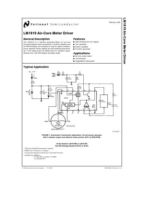
TL H 5263LM1819Air-Core Meter DriverFebruary 1995LM1819Air-Core Meter DriverGeneral DescriptionThe LM1819is a function generator driver for air-core (moving-magnet)meter movements A Norton amplifier and an NPN transistor are included on chip for signal condition-ing as required Driver outputs are self-centering and devel-op g 4 5V swing at 20mA Better than 2%linearity is guar-anteed over a full 305-degree operating rangeFeaturesY Self-centering 20mA outputs Y 12V operation Y Norton amplifier YFunction generatorApplicationsY Air-core meter driver Y TachometersYRuggedized instrumentsTypical ApplicationTL H 5263–1FIGURE 1 Automotive Tachometer Application Circuit shown operates with 4cylinder engine and deflects meter pointer (270 )at 6000RPMOrder Number LM1819M or LM1819N See NS Package Number M14A or N14ATRW Type X463UW Polycarbonate Capacitor RN60D Low TC Resistor (g 100ppm)Components Required for Automotive Load Dump Protection Available from FARIA CoP O Box 983 Uncasville CT 06382Tel 203-848-9271C 1995National Semiconductor Corporation RRD-B30M115 Printed in U S AAbsolute Maximum RatingsIf Military Aerospace specified devices are required please contact the National Semiconductor Sales Office Distributors for availability and specifications Supply Voltage V a(pin13)20V Power Dissipation(note1)1300mW Operating Temperature b40 C to a85 C Storage Temperature b65 C to b150 C Lead Temp (Soldering 10seconds)260 C BV CEO20V MINElectrical Characteristics V S e13 1V T A e25 C unless otherwise specifiedSymbol Parameter Pin(s)Conditions Min Typ Max UnitsI S Supply Current13Zero Input Frequency65mA(See Figure1)V REG Regulator Voltage11I REG e0mA8 18 58 9VRegulator Output Resistance11I REG e0mA to3mA13 5XV REF Reference Voltage4I REF e0mA1 92 12 3VReference Output Resistance4I REF e0m A to50m A5 3k XNorton Amplifier Mirror Gain5 6I BIAS j20m A0 91 01 1h FE NPN Transistor DC Gain9 10125Function Generator Feedback1V1e5 1V1 0mABias CurrentDrive Voltage Extremes 2 12I LOAD e20mAg4g4 5V Sine and CosineSine Output Voltage2V8e V REFb3500a350mV with Zero InputFunction Generator Linearity FSD e305 g1 7%FSD k Function Generator Gain Meter Deflection D V850 7553 7556 75 V Note1 For operation above25 C the LM1819must be derated based upon a125 C maximum junction temperature and a thermal resistance of76 C W which applies for the device soldered in a printed circuit board and operating in a still-air ambientApplication HintsAIR-CORE METER MOVEMENTSAir-core meters are often favored over other movements as a result of their mechanical ruggedness and their indepen-dence of calibration with age A simplified diagram of an air-core meter is shown in Figure2 There are three basic pieces a magnet and pointer attached to a freely rotating axle and two coils each oriented at a right angle with re-spect to the other The only moving part in this meter is the axle assembly The magnet will tend to align itself with the vector sum of H fields of each coil where H is the magnetic field strength vector If for instance a current passes through the cosine coil(the reason for this nomenclature will become apparent later)as shown in Figure3(a) the magnet will align its magnetic axis with the coil’s H field Similarly a current in the sine coil(Figure3(b))causes the magnet to align itself with the sine H field If currents are applied simultaneously to both sine and cosine coils the magnet will turn to the direction of the vector sum of the twoH fields(Figure3(c)) H is proportional to the voltage appliedto a coil Therefore by varying both the polarity and magni-tude of the coil voltages the axle assembly can be made to rotate a full360 The LM1819is designed to drive the me-ter through a minimum of305TL H 5263–2 FIGURE2 Simplified Diagram of an Air Core Meter2Application Hints (Continued)TL H 5263–3(c)(b)(a)FIGURE 3 Magnet and pointer position are controlled by the H field generated by the two drive coilsIn an air-core meter the axle assembly is supported by two nylon bushings The torque exerted on the pointer is much greater than that found in a typical d’Arsonval movement In contrast to a d’Arsonval movement where calibration is a function of spring and magnet characteristics air-core me-ter calibration is only affected by the mechanical alignment of the drive coils Mechanical calibration once set at manu-facture can not changeMaking pointer position a linear function of some input is a matter of properly ratioing the drive to each coil The H field contributed by each coil is a function of the applied current and the current is a function of the coil voltage Our desired result is to have i (pointer deflection measured in degrees)proportional to an input voltagei e kV IN 1 where k is a constant of proportionality with units of de-grees volt The vector sum of each coils’H field must followthe deflection angle i We know that the axle assembly always points in the direction of the vector sum of H SINE and H COSINE This direction (see Figure 4)is found from the formula(i )e arctan l H SINE l l H COSINE l 2 Recalling some basic trigonometry(i )e arctan(sin (i ) cos(i ))3TL H 5263–4FIGURE 4 The vector sum of H COSINE and H SINE points in a direction i measured in a clockwise direction from H COSINEComparing 3 to 2 we see that if H SINE varies as the sine of i and H COSINE varies as the cosine of i we will gener-ate a net H field whose direction is the same as i And since the axle assembly aligns itself with the net H field the point-er will always point in the direction of i THE LM1819Included in the LM1819is a function generator whose two outputs are designed to vary approximately as the sine and cosine of an input A minimum drive of g 20mA at g 4V is available at pins 2(sine)and 12(cosine) The common side of each coil is returned to a 5 1V zener diode reference and fed back to pin 1For the function generator k j 54 V (in equation 1) The input (pin 8)is internally connected to the Norton amplifier’s output V IN as considered in equation 1 is actually the dif-ference of the voltages at pins 8(Norton output function generator input)and 4 Typically the reference voltage at pin 4is 2 1V Thereforei e k(V 8b V REF )e 54(V 8b 2 1) 4 As V 8varies from 2 1V to 7 75V the function generator willdrive the meter through the chip’s rated 305 rangeAir-core meters are mechanically zeroed during manufac-ture such that when only the cosine coil is driven the point-er indicates zero degrees deflection However in some ap-plications a slight trim or offset may be required This is accomplished by sourcing or sinking a DC current of a few microamperes at pin 4A Norton amplifier is available for conditioning various input signals and driving the function generator A Norton amplifi-er was chosen since it makes a simple frequency to voltage converter While the non-inverting input (pin 6)bias is at one diode drop above ground the inverting input (5)is at 2 1V equal to the pin 4reference Mirror gain remains essentially flat to I MIRROR e 5mA The Norton amplifier’s output (8)is designed to source current into its load To bypass the Nor-ton amplifier simply ground the non-inverting input tie the inverting input to the reference and drive pin 8(Norton out-put function generator input)directlyAn NPN transistor is included on chip for buffering and squaring input signals Its usefulness is exemplified in Fig-ures 1 6where an ignition pulse is converted to a rectan-gular waveform by an RC network and the transistor The emitter is internally connected to ground It is important not to allow the base to drop below b 5V dc as damage may occur The 2 1V reference previously described is derived from an 8 5V regulator at pin 11 Pin 11is used as a stable supply for collector loads and currents of up to 5mA are easily accommodated 3Application Hints(Continued) TACHOMETER APPLICATIONA measure of the operating level of any motor or engine is the rotational velocity of its output shaft In the case of an automotive engine the crankshaft speed is measured using the units‘‘revolutions per minute’’(RPM) It is possible to indirectly measure the speed of the crankshaft by using the signal present on the engine’s ignition coil The fundamental frequency of this signal is a function of engine speed and the number of cylinders and is calculated(for a four-stroke engine)from the formulaf e n0 120(Hz)(5)where n e number of cylinders and0e rotational velocity of the crankshaft in RPM From this formula the maximum fre-quency normally expected(for an8cylinder engine turning 4500RPM)is300Hz In certain specialized ignition systems (motorcycles and some automobiles)where the coil wave-form is operated at twice this frequency(f e0 60) These systems are identified by the fact that multiple coils are used in lieu of a single coil and distributor Also the coils have two outputs instead of oneA typical automotive tachometer application is shown in Fig-ure1 The coil waveform is filtered squared and limited by the RC network and NPN transistor The frequency of the pulse train at pin9is converted to a proportional voltage by the Norton amplifier’s charge pump configuration The igni-tion circuit shown in Figure5is typical of automotive sys-tems The switching element‘‘S’’is opened and closed in synchronism with engine rotation When‘‘S’’is closed en-ergy is stored in Lp When opened the current in Lp diverts from‘‘S’’into C The high voltage produced in Ls when‘‘S’’is opened is responsible for the arcing at the spark plug The coil voltage(see Figure6)can be used as an input to the LM1819tachometer circuit This waveform is essentially constant duty cycle D4rectifies this waveform thereby pre-venting negative voltages from reaching the chip C4and R5form a low pass filter which attenuates the high frequen-cy ringing and R7limits the input current to about2 5mA R6acts as a base bleed to shut the transistor OFF when ‘‘S’’is closed The collector is pulled up to the internal regu-lator by R REG The output at pin9is a clean rectangular pulseMany ignition systems use magnetic hall effect or optical sensors to trigger a solid state switching element at‘‘S ’’These systems(see the LM1815)typically generate pulses of constant width and amplitude suitable for driving the charge pump directlyThe charge pump circuit in Figure7can be operated in two modes constant input pulse width(C1acts as a coupling capacitor)and constant input duty cycle(C1acts as a differ-entiating capacitor) The transfer functions for these two modes are quite diverse However deflection is always di-rectly proportional to R2and ripple is proportional to C2The following variables are used in the calculation of meter deflectionsymbol descriptionn number of cylinders0 0IDLE engine speed at redline and idle RPMi pointer deflection at redline degreese charge pump input pulse width secondsV IN peak to peak input voltages voltsDi maximum desired ripple degreesk function generator gain degrees voltf f IDLE input frequency at redline and idle HzWhere the NPN transistor and regulator are used to create a pulse V IN e8 5V Acceptable ripple ranges from3to10de-grees(a typical pointer is about3degrees wide)depending on meter damping and the input frequencyThe constant pulse width circuit is designed using the fol-lowing equations(1)100m A kV INR1k3mA(2)C1t10eR1(3)R2eR1iV IN e k fe120R1iV IN n0e k(4)C2e1R2Di f IDLEe1R2Di n0IDLEThe constant duty cycle equations are as followsR REG t3k XR1s V IN x104b R REGC1s e 10(R REG a R1)R Z e i 3 54n0C1e i 425f C1C2e425C1 DiThe values in Figure1were calculated with n e4 0e6000RPM i e270degrees e e1ms V IN is V REG b0 7V and Di e3degrees in the constant duty cycle mode For distributorless ignitions these same equations will apply if0 60is substituted for f4Equivalent SchematicT L H 5263–125Typical ApplicationsTL H 5263–9FIGURE 5 Typical Pulse-Squaring Circuit forAutomotive TachometersTL H 5263–10FIGURE 6 Waveforms Encountered in AutomotiveTachometer CircuitTL H 5263–11FIGURE 7 Tachometer Charge PumpVoltage Driven Meter with Norton Amplifier BufferTL H 5263–5Deflection e 54(V IN b 7)R 2 R 1(degrees)0to 305 deflection is obtained with 7to 5V input Full scale deflection is adjusted by trimming R 26Typical Applications(Continued)Unbuffered Voltage Driven MeterTL H 5263–6 Deflection e54(V IN b2 1)(degrees)0to305 deflection is obtained for inputs of2 1to7 75VFull scale deflection is adjusted by trimming the input voltageCurrent Driven MeterTL H 5263–7 Deflection e54R2I IN(degrees)Inputs of0to100m A deflect the meter0to270Full scale deflection is adjusted by trimming R27Typical Applications(Continued)Level Shifted Voltage Driven MeterTL H 5263–8 Deflection e54V IN(degrees)Inputs of0to5 65V deflect the meter through a range of0to305Full scale deflection is adjusted by trimming the input voltage8Physical Dimensions inches(millimeters)14-Lead(0 150 Wide)Molded Small Outline Package JEDECOrder Number LM1819MNS Package Number M14A9L M 1819A i r -C o r e M e t e r D r i v e rPhysical Dimensions inches (millimeters)(Continued)Molded Dual-In-Line Package (N)Order Number LM1819N NS Package Number N14ALIFE SUPPORT POLICYNATIONAL’S PRODUCTS ARE NOT AUTHORIZED FOR USE AS CRITICAL COMPONENTS IN LIFE SUPPORT DEVICES OR SYSTEMS WITHOUT THE EXPRESS WRITTEN APPROVAL OF THE PRESIDENT OF NATIONAL SEMICONDUCTOR CORPORATION As used herein 1 Life support devices or systems are devices or 2 A critical component is any component of a life systems which (a)are intended for surgical implant support device or system whose failure to perform can into the body or (b)support or sustain life and whose be reasonably expected to cause the failure of the life failure to perform when properly used in accordance support device or system or to affect its safety or with instructions for use provided in the labeling can effectivenessbe reasonably expected to result in a significant injury to the userNational Semiconductor National Semiconductor National Semiconductor National Semiconductor CorporationEuropeHong Kong LtdJapan Ltd1111West Bardin RoadFax (a 49)0-180-530858613th Floor Straight Block Tel 81-043-299-2309。
LINAK DESKLIFT
选项:• PLUS™:光滑的外部轮廓,无冲压痕• PLUS ™升降柱适用于标准连接块• 可选配工作台连接块• 可作为DESKLIFT™套装提供在完全缩回长度为560 mm 和行程长度为650mm 的情况下,标准系统可获得600 mm 至1250 mm 的桌面高度调整,因此,办公桌既可用于坐着工作,也可用于站着工作。
请注意:使用带显示屏的桌面板时,使用前必须将灯光亮度设置为50%。
DESKLIFT™ DL19 IC (集成控制)是一款基于 DL19 而开发的紧凑型三段式升降柱。
对于只使用两根升降柱,但需要最大可调范围的经济型升降办公桌来说,DL19IC 堪称完美之选。
DL19 IC 升降柱的外管尺寸和安装孔与 DL18 IC 二段式升降柱相同。
因此,它们可用于相同的桌面和桌脚结构。
对于工作台解决方案,升降柱可选配工作台连接块一起使用。
DL19 IC 升降柱十分坚固,电机外壳结构紧凑,可让升降柱与各种桌面设计轻松整合。
DL19IC 升降柱有三种标准配色(黑色、灰色和白色),但也可根据需要选配其他颜色。
DL19IC 还可选配让设计变得简洁的隐形滑垫。
IC 系统由两根升降柱组成,分别为主升降柱与副升降柱,两根升降柱由电机电缆连接。
主升降柱含内置PCB 控制器,因此IC 系统无需另外安装控制盒。
主电源是一个外部SMPS (开关电源)单元,且办公桌可使用多种手控器进行调节。
特性:• 设计紧凑,导向装置和推杆功能集成于一个单元。
• 增强型升降柱,优化了电机外壳设计,具有更高的强度和稳定性• 配备电机外壳的三段式升降柱• 方形,外管尺寸70 x 70 mm • 旨在优化设计的隐形滑动垫• 最大负载:每个升降柱为500 N • 最大速度:38 mm/s (空载)• 标准安装尺寸:560 mm • 标准行程长度:650 mm • 重量:每根升降柱重为8.3 kg • 电机外壳尺寸:177 x 97 x 46 mm• 颜色:可选颜色:黑色(RAL 9005)、银灰色(RAL 9006)与白色(RAL 9016)推杆 DL19 IC使用:• 2个升降柱同步驱动(一个DL19 IC 主升降柱和一个DL19 IC 副升降柱);1个外部电源(SMPS001(230V)、SMPS002(120V )或SMPS006(通用型))• 工作占空比:10 % ≈ 满负荷连续使用2分钟,然后暂停18分钟• 环境温度:10至40°C• 存储和运输温度:-10至+70 °C • 与DESKLINE ®控制器兼容• 与Kick & Click TM 安装解决方案兼容• 与DESKLIFT™支脚兼容•系统符合性,请参见《用户手册》中的“符合性声明”请注意,创建带工作台支架升降柱的选型编号,是假定从用户的位置看,且把主升降柱位于桌子右侧,副升降柱位于桌子左侧。
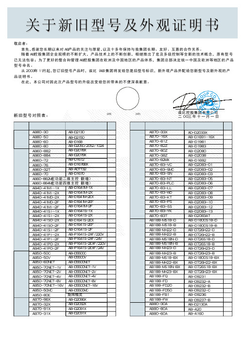
诶比(AB)新旧型号对照表
AB-D2083-12 AB-D2083-13 AB-D2083AT AB-D1800S18-D
AB-D1800S18-B AB-D726H22-D AB-D726H22-B AB-D726S18-D AB-D726S18-B AB-D726H23-D
AB-D1676BX AB-ADTT32 AB-D1670
AB60-882M宏功能二维主控(新增)
AB60-884M宏功能四维主控(新增)
AB40-41MI-1X
AB-D1641M-1X
AB40-41MI-2X AB40-41MO-2X
AB-D1641M-2X AB-D1641M-2EX
AB40-41MO-2F
诶比控股集团有限公司 二00三年十一月一日
类型 新型号
旧型号
类型 新型号
主机 键盘
解码器
多媒体 辅助 设备
AB80-30
AB-D2130
AB80-50
AB-D2150
AB80-60 AB80-80 AB60-882 AB60-884 AB60-72
AB60-76 AB60-32T AB60-70
AB-D168 AB-D2050/2052/1024 AB-D2078X AB-D2079X AB-D1672
AB70-83-NT AB7 AB70-83-KT AB70-83-PS
AB70-83-SS AB70-83-YK AB70-83T AB188-MS18-D
AB188-MS18-B AB188-MH22-D AB188-MH22-B AB188-MS18N-D AB188-MS18N-B AB188-MH23-D
艾福乐 2000 系列 船用网络接入模块 说明书
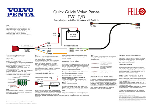
NOTEPlease see www.fell.no/support for more informationNOTEUse an AGC / 3AG – 1-3 Amp replacement fuse.If it is necessary to extend the power and ground wires, use 20 AWG or thicker wire.You can wire the Power Wires directly to the main boat battery, or if your boat has an electrical system, you might be able to wire the Power Wires to an unused holder on the fuse block.If your boat has an NMEA or NMEA2000 system installed you may be able to use this system as a powersupply for the WiMEA Boat Unit. Contact your engine manufacturer for more information.NMEA website: NOTEMAX Voltage for WiMEA Boat Unit is 32Vdc. Do not apply higher voltage as this will void your warranty and may break the unit.(10-32 Vdc)1. Use a test light or a voltmeter to determine the polarity of the voltage source.2. Connect the red (+ or positive) wire to the positive voltage terminal. (If you use the fuse block on the boat, route the positive connection through the fuse, as shown on the diagram.)3. Connect the black (- or ground) wire to the negative voltage terminal.4. Install or check the 1-3 A fuse (in the in-line fuse holder, or on the fuse block of the boat.5. Use wire hoods suitable for the wire dimension (20AWG, 0.75mm2) or connection point on theWiMEA Wireless Kill Switch can be installed together with your existing kill switch by connecting it in seriesor parallell. If you should connect in series or parallell depends on your existing kill switch function. Theabove picture shows an example with Normally Closed connection.Keep existing kill switchWhen WiMEA is installed this way the mechanical kill switch needs to be connected for the system to function properly.NOTEMake sure that all wire connections are waterproof by using heat shrinkable butt splices or similar when connecting wires.Use a crimping plier to squeeze the conducting part of the butt splice around the wire.Insert cables and ensure theconducting part of the cable makes good contact with the conducting part of the butt splice.Make sure all connections arewaterproof by applying heat to the end of the butt splice, which makes it shrink around the wire.Quick Guide Volvo PentaTo install WiMEA Wireless Kill Switch on a Volvo Penta with EVC-Ean original cable from Volvo Penta should be used. This cable has part number 21693202 and can be ordered by contacting FELL Support or directly from your closest Volvo Penta dealer.The signal cables on WiMEA consists of three wires. Only two of these are used for installation.1. Common – Grey – Always used whenconnecting the WiMEA Boat Unit Signal wires.Connect to green/red wire.2. Normally Open (NO) – Blue – Used when your existing system is Normally Open as Volvo Penta EVC-E.Connect to green/orange wire.FELL recommend that you use same type of crimp terminal as on the Volvo Penta cable when installing. This is to avoid breaking in the original Volvo Penta cable.After correct installatino has been done the systemneeds to be autoconfigured. For more information on how to do this, contact your closes Volvo Penta Dealer.Connect signal wiresIf your helm is made out of conducting materials thewireless signals from WiMEA may be degraded. The amount of signal degradation experienced may vary from across boats and must be tested for each case. If the signal is very poor you can install a separate external antenna outside of your helm to increase the signal strength. Please contact FELL support at www.fell.no/support for more information.Installation in a metal boatIf you have a twin engine installation in your boat with EVC-E, another cable should be used. The part number for this is 21693206. The installation of this cable is the same as in this manual, except there is two wires to HCU, one for each engine.Twin installationThe cable for Volvo Penta EVC-E used in this illustra-tion has part number 21693202. This cable can be ordered by contacting FELL Support or directly from your closest Volvo Penta dealer.In EVC-D there is an existing wire in the ignition which can be connected in the same way as shown in ”Con-nection signal wires”.Older EVC uses a cable with part number 3817104 which can be connected in the same way as shown in ”Connection signal wires”.This cable can be ordered by contacting FELL Support or directly from your closest Volvo Penta dealer.For older Volvo Penta without EVC, see installation instruction for connecting WiMEA directly to ignition or stop circuit.Older Volvo Penta and EVC-DNOTEDo not touch or cut any existing wires orelectrically conducting components before you make sure the main voltage switch is OFF. Only set the main voltage switch to ON after you arePlease see www.fell.no/support for more informationNOTEUse an AGC / 3AG – 1-3 Amp replacement fuse.If it is necessary to extend the power and ground wires, use 20 AWG or thicker wire.You can wire the Power Wires directly to the main boat battery, or if your boat has an electrical system, you might be able to wire the Power Wires to an unused holder on the fuse block.If your boat has an NMEA or NMEA2000 system installed you may be able to use this system as a powersupply for the WiMEA Boat Unit. Contact your engine manufacturer for more information.NMEA website: NOTEMAX Voltage for WiMEA Boat Unit is 32Vdc. Do not apply higher voltage as this will void your warranty and may break the unit.(10-32 Vdc)1. Use a test light or a voltmeter to determine the polarity of the voltage source.2. Connect the red (+ or positive) wire to the positive voltage terminal. (If you use the fuse block on the boat, route the positive connection through the fuse, as shown on the diagram.)3. Connect the black (- or ground) wire to the negative voltage terminal.4. Install or check the 1-3 A fuse (in the in-line fuse holder, or on the fuse block of the boat.5. Use wire hoods suitable for the wire dimension (20AWG, 0.75mm2) or connection point on theConnecting the PowerWiMEA Wireless Kill Switch can be installed together with your existing kill switch by connecting it in series or parallell. If you should connect in series or parallell depends on your existing kill switch function. Theabove picture shows an example with Normally Closed connection. It is very important that both kill switches are tested after installation to make sure the installation was done properly.Keep existing kill switchWhen WiMEA is installed this way the mechanical kill switch needs to be connected for the system to function properly.NOTEMake sure that all wire connections are waterproof by using heat shrinkable butt splices or similar when connecting wires.Use a crimping plier to squeeze the conducting part of the butt splice around the wire.Insert cables and ensure theconducting part of the cable makes good contact with the conducting part of the butt splice.Make sure all connections arewaterproof by applying heat to the end of the butt splice, which makes it shrink around the wire.Quick guide for boats withoutexisting kill switchInstallation of WiMEA Wireless Kill Switch toignition or stop circuitThe stop function in WiMEA Wireless Kill Switch con-sists of a mechanical relay and can thus be installed on boats without an existing kill switch.It is important to note that installation will vary betwe-en different engine brands and this guide is just to be used as a reference.The signal cables on WiMEA consists of three wires. Only two of these three wires should be used when installing the system.1. Common – Grey - Always used when connecting WiMEA, independent on if the system is normally open (Open to Stop) or normally closed (Close to Stop).See relevant schematic above to see where to connect they gray wire. This may change depending on type of boat and must be verified.2. Open to Stop(OS) – Blue – Used if your system needs short circuit to run.See relevant schematic above to see where to connect they blue wire. This may change depending on type of boat and must be verified.2. Close to Stop(CS) – Orange – Used if your system needs short circuit to stop.See relevant schematic above to see where to connect they blue wire. This may change depending on type ofboat and must be verified.Connecting the signal wiresWiMEA Wireless Kill Switch can be connected in series with the ignition. This will allow your WiMEA to cut the power in the ignition and in turn stop the engine. If you fall over board the WiMEA deactivates it’sinternal relay and cuts the power through the ignition. FELL recommends to use an external relay for this connection to protect the WiMEA from overcurrent. A standard automotive 12V/24V relay can be used for this purpose. Make sure the relay is rated for higher current than the ones going through your ignition.IgnitionWiMEA Wireless Kill Switch can be connected to your existing stop circuit if you have a stop button or similar. In the schematic above an example on how to connect is given where the existing stop button is kept in addition to WiMEA. If the current running in your stop circuit is exceeds 6A a realy should be used. This is to avoid overloading the switch inside WiMEA. A standard automotive 12V/24V relay can be used for this purpose. Make sure the relay is rated for higher current than the measured current in your stop circuit.Stop circuitIgnition exampleIf your helm is made out of conducting materials thewireless signals from WiMEA may be degraded. The amount of signal degradation experienced may vary from across boats and must be tested for each case. If the signal is very poor you can install a separate external antenna outside of your helm to increase the signal strength. Please contact FELL support at www.fell.no/support for more information.Installation in a metal boat。
LB1868中文资料
Parameter
Symbol
Input voltage range
ICC
Common mode input voltage range
VICM
Conditions Conditions
Electrical Characteristics at Ta = 25˚C, Icc = 10 mA
Parameter
元器件交易网
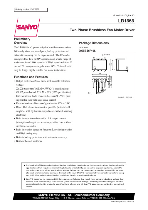
Ordering number : ENN*6202
LB1868
Monolithic Digital IC
LB1868
Two-Phase Brushless Fan Motor Driver
Preliminary Overview
The LB1868 is a 2-phase unipolar brushless motor driver. With only a few peripheral parts, lockup protection and automatic recovery can be implemented. The IC can be configured for 12V or 24V operation and a wide range of variations, from LOW speed to H-High speed and from 60 cm to 120 cm square using the same PCB. This makes it easy to design highly reliable fan motor installations.
GBLC18中文资料

GBLC03thruGBLC24CUL TRA LOW CAPACIT ANCE TVS ARRA YOnly One Name Means ProTek’Tion™APPLICA TIONS✔ Ethernet - 10/100/1000 Base T✔ Cellular Phones✔ Handheld - Wireless Systems ✔ Personnal Digital Assistant (PDA)✔ USB InterfaceIEC COMP A TIBILITY (EN61000-4)✔ 61000-4-2 (ESD): Air - 15kV , Contact - 8kV ✔ 61000-4-4 (EFT): 40A - 5/50ns✔ 61000-4-5 (Surge): 12A, 8/20µs - Level 1(Line-Ground) & Level 2(Line-Line)FEA TURES✔ 350 Watts Peak Pulse Power per Line (tp = 8/20µs)✔ Unidirectional & Bidirectional Configurations ✔ Replacement for MLV (0805)✔ Protects One Power or I/O Port ✔ ESD Protection > 40 kilovolts ✔ Low Clamping Voltage✔ Available in Multiple Voltage Types Ranging from 3V to 24V ✔ ULTRA LOW CAPACITANCE: 3pF T ypicalMECHANICAL CHARACTERISTICS✔ Molded JEDEC SOD-323✔ Weight 10 milligrams (Approximate)✔ Flammability rating UL 94V-0✔ 8mm Tape and Reel Per EIA Standard 481✔ Device Marking: Marking Code & Polarity Band (Unidirectional Only)05126PIN CONFIGURA TIONSSOD-323UNIDIRECTIONALBIDIRECTIONALGBLC24CDEVICE CHARACTERISTICSMAXIMUM RATINGS @ 25°C Unless Otherwise SpecifiedPeak Pulse Power (t p = 8/20µs) - See Figure 1Operating T emperature SYMBOL VALUE -55°C to 150°C°C°C -55°C to 150°C Watts UNITS 350T J P PP T STGPARAMETERStorage T emperatureNote 1: Part numbers with an additional “C” suffix are bidirectional devices, i.e., GBLC05C.Note 2: For Bidirectional Devices Only: Electrical characteristics apply in both directions.ELECTRICAL CHARACTERISTICS PER LINE @ 25°C Unless Otherwise SpecifiedPART NUMBER (See Note 1& Note 2)DEVICE MARKINGMINIMUM BREAKDOWN VOLTAGE@ 1mA V (BR)VOLTS MAXIMUM CLAMPING VOLTAGE (See Fig. 2)@ I P = 1AV C VOLTS MAXIMUM CLAMPING VOLTAGE (See Fig. 2)@8/20µs V C @ I PP TYPICAL CAPACITANCE@0V , 1 MHzC pFGBLC03GBLC03C GBLC05GBLC05C GBLC08GBLC08C GBLC12GBLC12C GBLC15GBLC15C GBLC18GBLC18C GBLC24GBLC24C33C 55C 88C 22C 66C 11C 44C4.04.06.06.08.58.513.313.316.716.720.020.026.726.77.07.09.89.813.413.419.019.024.024.029.029.043.043.019.0V @ 20.0A 19.0V @ 20.0A 18.3V @ 17.0A 18.3V @ 17.0A 18.5V @ 17.0A 18.5V @ 17.0A 28.6V @ 11.0A 28.6V @ 11.0A 31.8V @ 10.0A 31.8V @ 10.0A 45.0V @ 8.0A 45.0V @ 8.0A 56.0V @ 6.0A 56.0V @ 6.0A33333333333333MAXIMUM LEAKAGE CURRENT@V WMI D µA 55552211111111RATED STAND-OFF VOLTAGEV WM VOLTS3.33.35.05.08.08.012.012.015.015.018.018.024.024.0FIGURE 2PULSE WAVE FORMFIGURE 1PEAK PULSE POWER VS PULSE TIME0.01 1 10 100 1,000 10,000t d - Pulse Duration - µs0 5 10 15 20 25 30t - Time - µs20406080100120I P P - P e a k P u l s e C u r r e n t - % o f I P P101001,00010,000P P P - P e a k P u l s e C u r r e n t - W a t t sGBLC24CCOPYRIGHT © ProTek Devices 2003SPECIFICA TIONS: ProT ek reserves the right to change the electrical and or mechanical characteristics described herein without notice (except JEDEC).DESIGN CHANGES: ProT ek reserves the right to discontinue product lines without notice, and that the final judgement concerning selection and specifications is the buyer’s and that in furnishing engineering and technical assistance, ProTek assumes no responsibility with respect to the selection or specifications of such products.PACKAGE OUTLINE & DIMENSIONSProTek Devices2929 South Fair Lane, Tempe, AZ 85282Tel: 602-431-8101 Fax: 602-431-2288E-Mail: sales@ Web Site: 。
爱尔顿空冷备用生电器系统9千瓦和11千瓦说明书

1Air-cooled standby generator systems 9 kW and 11 kWSystem overview• Complete backup power system featuring afull line of Eaton automatic transfer switchesand generators• Exclusive national Eaton Certified ContractorNetwork (ECCN) contractors for installation,maintenance, and service• Local sales expertise and round-the-clocktelephone pre-/post-sales technical supportEGSX200NSEAEGENA11T able 1. Generator featuresFeatures BenefitsEngine• Overhead valve industrial enginedesign (OHVI)• ”Spiny-lok” cast iron cylinder walls• Electronic ignition/spark advance• Full pressure lubrication system• Low oil pressure shutdown system• High temperature shutdown • Maximizes engine “breathing” for increased fuel efficiency. Plateau-honed cylinder walls and plasma moly rings help engine run cooler, reducing oil consumption. Because heat is the primary cause of engine wear, the OHVI has a significantly longer life than competitive engines • Rigid construction and added durability provide long engine life• Assured smooth, quick start every time• Pressurized lubrication to all vital bearings means better performance, less maintenance, and significantly longer engine life. Now featuring a 2-year/200-hour oil change interval• Superior shutdown protection prevents catastrophic engine damage from low oil• Prevents damage due to overheatingGenerator• Revolving field• Skewed stator (only)• Displaced phase excitation• Automatic voltage regulation• UL T 2200 Listed • Allows for smaller, lightweight unit that operates 25% more efficiently than a revolving armature generator• Produces a smooth output waveform for electronic equipment compatibility• Maximizes motor starting capability• Regulates the output voltage to ±2%, which prevents damaging voltage spikes• Compliant with all safety regulationsNew controller and controls• Auto/Manual/Off illuminated buttons• Utility voltage sensing• Utility interrupt delay• Engine warm up• Engine cool down• Main line circuit breaker• Electronic governor• Smart battery charger• Two-Line LCD multilingual display• Sealed, raised buttons• Generator voltage sensing• Programmable exercise • Selects the operating mode for easy, at-a-glance status indication in any condition• Weather-resistant interface allows smooth programming and operations for the user• Constantly monitors utility voltage, set points 60% dropout, and 80% pickup of standard voltage • Ensures engine is ready to assume the load, set point approximately 5 seconds• Allows engine to cool prior to shutdown, set point approximately 1 minute• Protects generator from overload• Maintains constant 60 Hz frequency• Delivers charge to the battery only when needed at varying rates depending on outdoor air temperature. Compatible with lead acid and AGM-style batteries• Provides homeowners easily visible logs of history, maintenance, and events up to 50 occurrences • Smooth, weather-resistant user interface for programming and operations• Constantly monitors generator voltage to ensure the cleanest power delivered to the home• Operates engine to prevent oil seal drying and damage between power outages by running the generator for 12 minutes every other week. Also offers a selectable setting for weekly or monthly operation providing flexibility and potentially lower fuel costs to the ownerUnit• SAE weather-protective enclosure• Enclosed critical grade muffler• Small, compact, attractive • Sound attenuated enclosures ensure quiet operation and protection against Mother Nature, withstanding winds up to 150 mph. Hinged key locking roof panel for security. Lift-out front for easy access to all routine maintenance items. Electrostatically applied textured epoxy paint for added durability• Quiet, critical grade muffler is mounted inside the unit to prevent injuries. Complies with local dB noise levels• Makes for an easy, eye-appealing installationInstallation system• 1-foot flexible fuel line connector• Direct-to-dirt composite mounting pad• Integral sediment trap • Easy installation• Complex lattice design prevents settling or sinking of the generator system• Prevents particles and moisture from entering the fuel regulator and engine, prolonging engine lifeWarranty a• 5-year limited warranty:• Years 1 and 2—limited comprehensive coverage on mileage, labor, and parts (warranty certification required)• Year 3—limited comprehensive coverage on parts only• Years 4 and 5—limited comprehensive coverage on engine (short block) and alternator (rotor and stator) parts only a For warranty details, refer to the “Eaton Air-Cooled Automatic Standby Generators” warranty statement.T able 2. Compatible automatic transfer switches aFeatures BenefitsEGSU series featuringuniversal active loadmanagement• Truly active load management system• RTC-100 controller with built-in intelligence• Universal compatibility with any generator brand (single-phase, 240 V)• No programming necessary• Whole house surge included (catalog number: CHSPT2ULTRA)• 50 or 60 Hz• Current sensors (CTs) included• Built-in 7-, 14-, and 28-day plant exerciser• Load and no-load transfer• Meets NEC T Article 702.5 for optional standby backup power systems• UL 1008 Listed• Actively balances electrical loads in the household, adjusting tohomeowner’s lifestyle• Complete home surge protector included to protect home electronicsand appliances against surge events• Complete power monitoring for greater accuracy and load management:voltage, current, and frequency• Power monitoring system allows 100% use of power output ratingin the generator• Contractor-friendly installation, requires fewer connections tothe generator• Environmentally friendly: allows downsizing of generator resultingin decrease of greenhouse gas (GHG) emissions, and reduces gasconsumption by 15% or moreEGSX series featuringload shedding• Two sets of contacts for load shedding• Simplified, non-redundant relay-interface system• Terminal block termination; connections labeled to match generatorconnections• Three-point keyhole mounting system for quick, level installation• Optimal wire bending space• Commercial grade main breaker included• UL 1008 compliant• Meets NEC Article 702.5 for optional standby backup power systems• Easy, intuitive installation for labor savings• Compatible with Eaton generators and most standby generator brands• Smallest footprint in the industry (400 A model)Warranty b• 1-year limited warranty from the date of installation or 18 months from the date of shipment, whichever occurs first• Extended and special warranties available:• 24 months—2% of contract price• 30 months—3% of contract price• 36 months—4% of contract pricea For selection information, visit our online green ATS interactive demo at .b For warranty details, refer to Eaton Selling Policy 25-000.T able 3. Automatic transfer switch specificationsAmperes VoltagesNumberof polesServiceentranceNumberof circuitsincluded a FrequencyEnclosuretypeContactorwire sizeranges(s)Numberof cablesper phaseWithstandcurrent(rms) at240 VacMost commongeneratorsizes bCatalognumberEGSU series50120/2402—2450/60NEMA 3R#14–#2/0110,0009, 11, 16 kW EGSU100L24RACA 50120/2402——50/60NEMA 3R#14–#2/0110,0009, 11, 16 kW EGSU100ACA 100120/2402Y—50/60NEMA 3R#14–#2/0110,0009, 11, 16 kW ESGU100NSEACA 100120/2402Y—50/60NEMA 3R#4–300 kcmil125,0009, 11, 16 kW EGSU150NSEACA 200120/2402——50/60NEMA 3R#4–300 kcmil125,00016, 20, 22 kW EGSU200ACA 200120/2402Y—50/60NEMA 3R#4–300 kcmil125,00016, 20, 22 kW EGSU200NSEACA 200120/2402Y—50/60NEMA 3R750 kcmil–2 /300 kcmil–1/01/235,000>22 kW EGSU400NSEACA EGSX series50120/2402Y1250/60NEMA 1#14–#6150009, 11 kW EGSX50L12 50120/2402—1250/60NEMA 3R#14–#6150009, 11 kW EGSX50L12R 100120/2402——50/60NEMA 3R#14–#2/0110,0009, 11, 16 kW EGSX100A 100120/2402Y—50/60NEMA 3R#14–#2/0110,0009, 11, 16 kW EGSX100NSEA 100120/2402—2450/60NEMA 3R#14–#2/0125,0009, 11, 16 kW EGSX100L24RA 150120/2402Y—50/60NEMA 3R#4–300 kcmil125,00016, 20, 22 kW EGSX150NSEA 200120/2402——50/60NEMA 3R#4–300 kcmil125,00016, 20, 22 kW EGSX200A 200120/2402Y—50/60NEMA 3R#4–300 kcmil125,00016, 20, 22 kW EGSX200NSEA 400120/2402Y—50/60NEMA 3R750 kcmil–2 /300 kcmil–1/01/235,000>22 kW EGSX400NSEAa Uses CH type circuit breakers.b For reference only. Generator size must be determined by actual load calculations.T able 4. Generator specificationsCatalog numberEGENA9EGENA11 GeneratorRated maximum continuous power capacity (LP)/(NG)9000/8000 watts a11,000/10,000 watts a Enclosure Aluminum AluminumRated voltage240240Rated maximum continuous load current 240 V b37.5/33.3 NG45.8/41.7 NGTotal harmonic distortion Less than 5%Less than 5%Main line circuit breaker40 A50 APhase Single SingleNumber of rotor poles22Rated AC frequency60 Hz60 HzPower factor 1.0 1.0Battery requirement (not included)Group 26R, 12 V and525 cold-cranking amperes minimumor Group 35AGM 650 cold-crankingamperes minimum Group 26R, 12 V and525 cold-cranking amperes minimum or Group 35AGM 650 cold-cranking amperes minimumUnit weight lb (kg)340/154348 (158)Dimensions in inches (mm) L x W x H 48.00 x 25.00 x 29.00(1219.2 x 635.0 x 736.6)48.00 x 25.00 x 29.00(1219.2 x 635.0 x 736.6)Sound output in dBA at 23 ft with generatoroperating at normal load6663EngineType of engine OHVI OHVI V-TWINNumber of cylinders12Displacement410 cc530 ccCylinder block Aluminum with cast iron sleeve Aluminum with cast iron sleeve Valve arrangement Overhead valve Overhead valveIgnition system Solid-state with magneto Solid-state with magneto Governor system Electronic Electronic Compression ratio9.0:19.5:1Starter12 Vdc12 VdcOil capacity including filter Approximately 1.1 qt/1.0 L Approximately 1.7 qt/1.6 L Operating RPM3,6003,600Fuel consumption cNatural gas ft³/hr (m³/hr): 1/2 loadFull load 90 (2.55)120 (3.4)107 (3.03)159 (4.50)Liquid propane ft³/hr (gal/hr) (liters/hr): 1/2 loadFull load 31.6 (0.87) (3.29)50 (1.37) (5.2)44.4 (1.22) (4.62)71.6 (1.97) (7.45)a Suitable for “optional” standby backup power only, as indicated by NEC Article 702. Not suitable for legally required “emergency” life safety applications as required by NEC Article 700 and NFPA 110/99. All ratings in accordance with BS5514, ISO3046, and DIN6271. Maximum wattage and current are subject to and limited by such factors as fuel BTU content, ambient temperature, altitude, engine power, and condition. Maximum power decreases about 3.5% for each 1000 feet above sea level, and also will decrease about 1% for each 12 °C (10 °F) above 15.5 °C (60 °F).b LP = Liquid propaneNG = Natural gasc Gas pipe sizing is critical for the proper operation of the generator. Fuel pipe must be sized for full load. Required fuel pressure to generator fuel inlet at all load ranges—3.5 to 7 inches water column(7 to 13 mm mercury) for natural gas, 10 to 12 inches water column (19 to 22 mm mercury) for LP gas. For BTU content, multiply ft3/hr x 2500 (LP) or ft3/hr x 1000 (NG). For Megajoule content,multiply m3/hr x 93.15 (LP) or m3/hr x 37.26 (NG).T able 5. Generator controlsFeatures DescriptionTwo-line plain text multilingual LCD display Simple user interface for ease of operationMode buttonsAutoManualOffAutomatic start on utility failure. 7-day exerciser (7-, 14-, and 28-day exerciser when coupled with EGSU ATS)Start with starter control, unit stays on. If utility fails, transfer to load takes placeStops unit. Power is removed. Control and charger still operateReady to run/maintenance messages StandardEngine run hours indication StandardProgrammable start delay between 2 and 1500 seconds Standard (programmable by dealer only)Utility voltage loss/return to utility adjustable From 140 V to 171 V/190 V to 216 VFuture set capable exerciser/exercise set error warning StandardRun/alarm/maintenance logs50 events eachEngine start sequence Cyclic cranking 16 seconds on, 7 rest (90 seconds maximum duration)Starter lockout Starter cannot re-engage unit 5 seconds after engine has stoppedSmart battery charger StandardCharger fault/missing AC warning StandardLow battery/battery problem protection and battery condition indication StandardAutomatic voltage regulation with overvoltage and undervoltage protection StandardUnderfrequency/overload/stepper overcurrent protection StandardSafety fused/fuse problem protection StandardAutomatic low oil pressure/high oil temperature shutdown StandardOvercrank/overspeed at 72 Hz/RPM sense loss shutdown StandardHigh engine temperature shutdown StandardInternal fault/incorrect wiring protection StandardCommon external fault capacity StandardField-upgradable firmware StandardT able 6. Compatible accessories and replacement parts—EGENA generatorsDescription Benefits/features Catalog number Maintenance and general accessoriesBattery pad warmer The pad warmer rests under the battery. Recommended for use if the temperature regularly falls below 0 7F.(Not necessary for use with AGM-style batteries).7101CHOil warmer Oil warmer slips directly over the oil filter. Recommended for use if the temperature regularly falls below 0 7F.7102CH Breather warmer The breather warmer is for use in extreme cold weather applications. For use with standard controllersonly in climates where heavy icing occurs.7103CHMaintenance kit for 9 kW generators Includes all hardware and material necessary to perform scheduled preventive maintenance. Compatiblewith model EGENX9 only.6482CHMaintenance kit for 11 kW generators Includes all hardware and material necessary to perform scheduled preventive maintenance. Compatiblewith model EGENX11 only.6483CH Bisque color paint kit Ideal for touch-up paint/maintenance to generator enclosure against scratches and future corrosion.EGENPAINT Generator fascia Enhances aesthetics. Installs in seconds (standard with EGENX20A and EGENX22A models).EGENFASCIA Air-cooled transportation cart User-friendly assembly, attaches to lifting holes. Smart design allows only one person to lift the unitoff of wooden pallet and position it for final installation.EGENCART MonitoringMobile wireless remote monitor Most advanced generator status monitoring system. Allows connectivity and settings programmingvia smart devices (laptops, smartphone, pad, etc.). Sends automated emails and/or text messagesto multiple users. Requires cell phone signal and subscription.EGENMOBILEIn-house wireless monitor In-house generator status basic monitoring system. No computer connectivity required. 600 ft radiusof wireless coverage.EGENINHOME T able 7. Replacement parts—EGSX ATSComponent Catalog number50 A100 A150 A200 A400 AContactor99-5643-899-5638-1299-5702-1599-5702-1599-5702-16 Wire harness a99-5643-799-5638-1399-5702-1799-5702-1799-5702-18 Neutral bar99-5643-699-5638-799-5702-699-5702-699-5702-13 Ground lugs99-5643-499-5638-599-5702-499-5702-499-5702-4 Service entrance breaker—99-5638-4CSR2150CSR2200KD2400 Contactor lugs99-5643-599-5638-699-5702-599-5702-599-5702-12 a Includes relay and mounting base.T able 8. Replacement parts—EGSU ATSComponent Catalog number100 A150 A200 A400 AController RTC100RTC100RTC100RTC100 Contactor99-5638-1299-5702-1599-5702-1599-5702-16 Wire harness99-5638-1499-5702-799-5702-799-5702-19 Service entrance breaker99-5638-4CSR2150CSR2200KD2400 c Ground bar99-5638-5 a99-5702-49-5702-499-5702-4 Contactor lugs99-5638-699-5702-599-5702-599-5702-12 Neutral bar99-5638-7 b99-5702-699-5702-699-5702-13 Current sensors CS200CS200CS200CS400 Whole house surge protector CHSPT2ULTRA CHSPT2ULTRA CHSPT2ULTRA CHSPT2ULTRAa For EGSU100L24RACA, order ground bar catalog number 99-5638-15.b For EGSU100L24RACA, order neutral bar catalog number 99-5638-17.c For breaker lugs, order catalog number 2TA401K.Figure 1. Air-cooled generator 9 kW and 11 kW—dimensions in inches (mm) Dimensions shown are approximate. Design and specificationssubject to change without notice. For additional information, visitour website at , call our technicalresource center at (877) ETN-CARE (386-2273), or contact yourlocal Eaton authorized distributor.Eaton1000 Eaton Boulevard Cleveland, OH 44122 United States © 2016 EatonAll Rights ReservedPrinted in USAPublication No. TD00405002E / Z19034 December 2016Eaton is a registered trademark.All other trademarks are propertyof their respective owners.Air-cooled standby generator systems 9 kW and 11 kWTechnical Data TD00405002EEffective December 2016Figure 2. Plan view of an EGSX150NSEA/EGSX200NSEA—dimensions in inches (mm)T able 9. Automatic transfer switches approximate dimensions in inches (mm)Amperes Width Height Depth Weight in lb (kg) 5014.25 (362.0)21.00 (533.4) 4.00 (101.6)23 (10.43) 10014.46 (367.3)16.87 (428.5) 5.32 (135.1)25 (11.33)100 with loadcenter14.46 (367.3)29.33 (745.0) 5.32 (135.1)38 (17.23) 15014.46 (367.3)29.33 (745.0) 5.32 (135.1)45 (20.41)200 a14.46 (367.3)29.33 (745.0) 5.32 (135.1)45 (20.41) 40023.14 (587.8)37.56 (954.0)10.00 (254.0)130 (58.96)a Height for 200 A non-SE is 25.08 (637.0).。
EIB总线概述

总线概述基本介绍EIB(European Installation Bus),是电气布线领域使用范围最广的行业规范和产品标准。
现已成为国际标准ISO/IEC 14543-3,并于2007年正式成为中国国标GB/Z 20965-2007。
EIB最大的特点是通过单一多芯电缆替代了传统分离的控制电缆和电力电缆,并确保各开关可以互传控制指令,因此总线电缆可以以线型、树型或星型铺设,方便扩容与改装。
元件的智能化使其可以通过编程来改变功能,既可独立完成诸如开关、控制、监视等工作,也可根据要求进行不同的组合。
与传统安装方式比较,EIB不增加元件数量而实现了功能倍增,从而具有了高度的灵活性。
它的开放性更使得不同公司基于EIB协议开发的电气设备可以完全兼容,并为后续公司进入EIB市场提供可能。
EIB系统既是一个面向使用者、体现个性的系统又是一个面向管理者的系统,使用者可根据个人的喜好任意修改系统的功能,达到自己所需要的效果,并可通过操作探测器(如按钮开关等)来控制系统的动作;另一方面, EIB系统还提供基于Windows的软件平台,管理者(如小区物业中心、大楼管理中心、车库管理处等)将安装此套软件的计算机连接至EIB系统即可对EIB系统进行控制并进行管理,从而达到集中管理的功能。
发展历史1990年5月8日,以ABB、SIEMENS、MERTEN、GIRA、JUNG等共七家欧洲著名的电气产品制造商为核心组成联盟,制订了欧洲安装总线规范(European Installation Bus),成立了中立的非商业性组织EIBA(European Installation Bus Association,欧洲安装总线协会),EIBA会员占据了欧洲楼宇、家庭自动化设备销售额的80%。
自EIB于1992年第一次出现在德国汉诺威交易会以来,一场翻天覆地的电气安装革命已经悄悄地开始了。
据统计,在德国的商业功能建筑和大型超市中,大约30%的楼宇都不同程度地安装了EIB系统,而在计划建造的楼宇中,这一比例则达到了60%。
康普艾压缩机QX189206 LB260_300 中文版用户手册
第4页
LB260-300 用户手册 标签
危险
危险
QX100432
QX100426
0422
第5页
LB260-300 用户手册 标签
警告
警告
警告
小心
警告
危险
QX100425
小心
警告
QX100427
QX100430
第6页
LB260-300 用户手册
第二部分
安装
危 险
忽视这些提示可能导致人身伤害甚至死亡。 手指和衣物要远离旋转的风扇,驱动联接等。 不要使用本设备排出的空气作呼吸用—不适合用于人体使用。 在机组停止运转且空气压力已经释放之前,不要松开或旋下压缩机空气或油系 统内的加油口盖,泄油口塞,盖,温控阀或拆开任何线路等。 电击可能是致命的。 根据国家电器标准与当地电器标准进行接线,这种接线工作必须由专业人员完 成。
危险
电动机上提供的吊环螺栓或凸缘只能用于起吊电动机,不应用来起吊任何附加的重量。 所有的吊环螺栓都必须 安全紧固。起吊电动机时,起吊角度不超过 15°。忽视此警告 可能导致设备损坏或人身伤害。 场所─空压机应安装在干净,光线充足,通风良好,周围有足够的维护空间的地方。选择一个能 提供凉爽,干净,干燥气源的场所。在某些情况下,在从空气供给点到压缩机的一段距离上安装 空气过滤器是很必要的。 压缩机机组需要向压缩机吸入空气一样的凉爽空气来冷却器电动机。必须供给良好的通风。 压缩机运转区的热空气必须排走。图 2-1 展示了一种典型的空气导入和流出的布置图。
在控制柜内操作前,断开主断电开关,作标记并停工。 在对机组从事任何工作之前,断开压缩机机组与它的动力源,作标记并停工─ 本机是自动控制的,随时都有可能启动。
埃 significance 产品说明书:Eaton 281944 CI-PKZ01-SVB-V 电
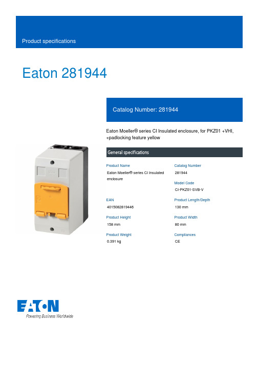
Eaton 281944Eaton Moeller® series CI Insulated enclosure, for PKZ01 +VHI, +padlocking feature yellowGeneral specificationsEaton Moeller® series CI Insulated enclosure281944CI-PKZ01-SVB-V4015082819446130 mm 158 mm 80 mm 0.391 kgCEProduct NameCatalog Number Model Code EANProduct Length/Depth Product Height Product Width Product Weight Compliances0 AAccessoriesIs the panel builder's responsibility. The specifications for the switchgear must be observed.0 W10 WMeets the product standard's requirements.Emergency stopIs the panel builder's responsibility. The specifications for the switchgear must be observed.Does not apply, since the entire switchgear needs to be evaluated.Meets the product standard's requirements.PE(N) terminalMeets the product standard's requirements.Meets the product standard's requirements.Is the panel builder's responsibility.Is the panel builder's responsibility.IP65 UKCA CI..-PKZ.. Surface mounted enclosures and accessories PKZ CE CI..-PKZ.. Surface mounted enclosures and accessories PKZeaton-small-enclosures-enclosure-ci-insulated-enclosure-dimensions-003.epseaton-manual-motor-starters-mounting-ci-insulated-enclosure-3d-drawing.epsDA-CE-ETN.CI-PKZ01-SVB-VIL03407018ZDA-CS-ci_pkz01_svbDA-CD-ci_pkz01_svbeaton-manual-motor-starters-transformer-pkzm0-wiring-diagram.epsRated operational current for specified heat dissipation (In) Product category10.11 Short-circuit ratingEquipment heat dissipation, current-dependent PvidHeat dissipation capacity Pdiss10.4 Clearances and creepage distancesSuitable for10.12 Electromagnetic compatibility10.2.5 Lifting10.2.3.1 Verification of thermal stability of enclosuresFitted with:10.2.3.2 Verification of resistance of insulating materials to normal heat10.2.3.3 Resist. of insul. mat. to abnormal heat/fire by internal elect. effects10.8 Connections for external conductors10.9.2 Power-frequency electric strengthDegree of protection Compliance information DrawingseCAD model Installation instructions mCAD modelWiring diagramsNEMA OtherAmbient operating temperature - max70 °C10.7 Internal electrical circuits and connectionsIs the panel builder's responsibility.FeaturesCan be locked in 0 position in combination with VHI-PKZ0110.10 Temperature riseThe panel builder is responsible for the temperature rise calculation. Eaton will provide heat dissipation data for the devices.Static heat dissipation, non-current-dependent Pvs0 W10.9.3 Impulse withstand voltageIs the panel builder's responsibility.Enclosure materialPlasticKnockoutsHard mirror with cable entry knockouts (can be cut out)2 x M25 (cable entry knockout with thread at the bottom) 2 x M25 (cable entry knockout with thread at the top)2 x M20 (cable entry knockouts at the rear)Ambient operating temperature - min-25 °C10.2.2 Corrosion resistanceMeets the product standard's requirements.10.6 Incorporation of switching devices and components Does not apply, since the entire switchgear needs to be evaluated.10.2.4 Resistance to ultra-violet (UV) radiationPlease enquire10.2.7 InscriptionsMeets the product standard's requirements.10.5 Protection against electric shockDoes not apply, since the entire switchgear needs to be evaluated.ModelSurface mountingEaton Corporation plc Eaton House30 Pembroke Road Dublin 4, Ireland © 2023 Eaton. All Rights Reserved. Eaton is a registered trademark.All other trademarks areproperty of their respectiveowners./socialmediaThe device meets the requirements, provided the information in the instruction leaflet (IL) is observed.Does not apply, since the entire switchgear needs to be evaluated.Is the panel builder's responsibility.Does not apply, since the entire switchgear needs to be evaluated.0 W10.13 Mechanical function10.2.6 Mechanical impact10.9.4 Testing of enclosures made of insulating material 10.3 Degree of protection of assembliesHeat dissipation per pole, current-dependent Pvid。
爱森·查林·低速高扭力轨道电机用于摇杆驱动(2014年10月)说明书

3
3.5
4
Number of teeth
13
13
11
Pressure angle
20
20
20
Pitch diameter
39
45.5
44
Add modification coefficient
0.614
0.5
0.55
Note: as per JIS standard Output torque is limited depending on pinion dimension In case of small pinion, output torque is limited less than spec..
2000 series
Swing Motor
2 P C 25 A 11 15
C
1
2
3
4
5
6
7
1
5
2 6
3
7
8 4
Model
2P*16
2P*20
2P*25
Motor displacement
cm3/rev 158
195
244
Max output torque
N∙m
369
411
418
Max pressure Max speed
Recommendation fluids: ISO VG32, 46, 56, 68 mineral oil Recommended system operation temperature: - 30˚C to 80˚C Recommended oil viscosity: 24 to 50 cSt Recommended cleanliness: ISO 18/13
艾富丽电机说明书
艾富丽电机说明书艾XX电机使用说明书概述本说明书适用于我公司生产的艾XX系列低压三相异步电动机。
The manual serves YX3、YET、Y2、YVP、YD Series low voltage asynchronous motors and it's derivative products as well.开始使用Putting into use (starting)收货检查Reception check收到电机后立即检查是否有损坏,如发现请立即拨打电话∶0086-21-6463-177,或发传真至0086-21-6463-7180,检查铭牌数据特别是额定电压、接线方式(星形或三角形)是否与合同订货要求相符,用手转动电机轴检查轴转动是否灵活。
Immediately check the motor for external damage upon receipt and if found, please inform us by telephone or fax without delay (Tel:0086-21-6463-177, Fax:0086-21-6463-7180). Check all rating plate data, especially voltage and winding connection (star or delta). Turn shaft by hand to check for free rotation.警告∶测量完绝缘电阻后应立即将测量线从电机上断开,以免线圈再次受到高电压冲击。
环境温度每升高20℃,绝缘电阻将降低一半,如果绝缘电阻值达不到计算值,表明线圈已经受潮需进行烘干处理。
先在90℃温度下烘12-16小时再在105℃下烘6-8小时。
WARNINGWindings should be discharged immediately after measurement to avoid risk for electric shock. Insulation resistance reference value is halved for each 20°Crise in ambient temperature. If the reference resistance value is not attained, the winding is too damp and must be oven dried. Oven temperature should be 90°C for 12-16 hours followed by 105°C for 6-8 hours.电机启动Motor starting① 单速电机启动(直接或Y/△启动)标准单速三相异步电动机的出线盒内有6个接线头和至少1个接地接头,接地须根据操作规程在电机接上电源前进行,接线方式和电压应根据接线指示牌及铭牌指示。
- 1、下载文档前请自行甄别文档内容的完整性,平台不提供额外的编辑、内容补充、找答案等附加服务。
- 2、"仅部分预览"的文档,不可在线预览部分如存在完整性等问题,可反馈申请退款(可完整预览的文档不适用该条件!)。
- 3、如文档侵犯您的权益,请联系客服反馈,我们会尽快为您处理(人工客服工作时间:9:00-18:30)。
20 850 46* ቤተ መጻሕፍቲ ባይዱ360 700 -2.0 -15 8
o
% mA dBm 1700 mA mS -3.5 V V C/W
Drain Breakdown Voltage Igd=4.8mA Thermal Resistance (Au-Sn Eutectic Attach)
*Typical –45dBc IM3 at Pout=23dBm/Tone
EIA1819-2P SYMBOLS PARAMETERS/TEST CONDITIONS Output Power at 1dB Compression f=18.7-19.7GHz Vds=8V, Idsq=0.5 Idss(EIA), 0.6Idss(EIB) Gain at 1dB Compression f=18.7-19.7GHz Vds=8V, Idsq=0.5 Idss(EIA), 0.6Idss(EIB) Power Added Efficiency at 1dB compression f=18.7-19.7GHz Vds=8V, Idsq=0.5 Idss(EIA), 0.6Idss(EIB) Drain Current at 1dB Compression Output 3 Order Intercept Point f=18.7-19.7GHz Vds=8V, Idsq=0.5 Idss(EIA), 0.6Idss(EIB) Saturated Drain Current Vds=3V, Vgs=0V Transconductance Pinch-off Voltage Vds=3V, Vgs=0V Vds=3V, Ids=12mA -13 1100
MAXIMUM RATINGS AT 25OC
SYMBOLS Vds Vgs Ids Igsf Pin Tch Tstg Pt PARAMETERS Drain-Source Voltage Gate-Source Voltage Drain Current Forward Gate Current Input Power Channel Temperature Storage Temperature Total Power Dissipation ABSOLUTE1 12V -8V Idss 180mA 32dBm 175oC -65/175oC 17W 8V -3V Idss 30mA @ 3dB Compression 150oC -65/150oC 14.2W CONTINUOUS2
EIA/EIB1819-2P
Not recommended for new designs. Contact factory. Effective 03/2003 18.7-19.7GHz, 2W Internally Matched Power FET
ELECTRICAL CHARACTERISTICS (Ta = 25 OC)
元器件交易网
Excelics
• • • • • • 18.7-19.7GHz BANDWIDTH AND INPUT/OUTPUT IMPEDANCE MATCHED TO 50 OHM EIA FEATURES HIGH PAE( 25% TYPICAL) EIB FEATURES HIGH IP3(46dBm TYPICAL) +33.0/+32.5dBm TYPICAL P1dB OUTPUT POWER FOR EIA/EIB 6.0/5.0dB TYPICAL G1dB POWER GAIN FOR EIA/EIB NON-HERMETIC METAL FLANGE PACKAGE
rd
EIB1819-2P MAX MIN 32.0 4.5 TYP 32.5 5.0 MAX UNIT dBm dB
MIN 32.0 5.5
TYP 33.0 6.0
P1dB G1dB PAE Id1dB IP3 Idss Gm Vp BVgd Rth
25 880 40 1440 1500 -1.0 -15 8 -2.5 1700 1100
Note: 1. Exceeding any of the above ratings may result in permanent damage. 2. Exceeding any of the above ratings may reduce MTTF below design goals.
Excelics Semiconductor, Inc., 310 De Guine Drive, Sunnyvale, CA 94085
Phone: (408) 737-1711 Fax: (408) 737-1868 Web Site: