Control Strategies for Hybrid Electric Vehicles
碳酸亚乙烯酯添加剂对锂离子电池性能的影响
(EC)、碳酸丙烯酯(PC)、二乙基碳酸酯(DEC)、二甲基碳酸酯(DMC)。
溶剂均采用精馏结合分子筛吸附的方法提纯至纯度(质量分数)>-99.95%(气相色谱仪为GC-14C,日本岛津)。
电解液的配制及电池的装配均在充满高纯氩气的手套箱中进行【畎H20)<I10-6】,LiPF6浓度为1moFL。
电解液中水和酸(I-IF)含量均低于20x10-6,分别用KarlFisher水分测定仪KF831和KarlFisher电位滴定仪798GPTTitrino(瑞士万通)测定。
1.2电池性能测试电池电化学性能测试用CR2032扣式半电池,以MCMB电极片为正极,金属锂片作为负极,电解液为不含与含(质量分数)2%VC的lmoi/LLiPFc,/(EC:PC:DEC:DMC)=(3:1:4:21。
组装成半电池后,在室温下用Land多通道充放电测试系统在0.01~2.0V电压区间进行恒电流充放电实验。
金属锂片作为对电极和参比电极,MCMB电极为工作电极,在多通道测试系统(SolartronAnalytical1480Multistat,英国)上对电池进行循环伏安测试,扫描速率为0.2mV/s。
1.3表面性质分析用JSM.6510(JEOL)扫描电镜观察石墨电极表面的形貌,加速电压为15kV。
用ATR-IRNicoletiSl0(ThermoFish.er)傅里叶变换红外光谱研究电极表面的SEI膜成分,扫描范围680~2000cm—i。
2结果与讨论2.1石墨电极的循环伏安行为图l为石墨电极在不含VC(a)与含VC添加剂(b)的电解液体系中的前三次循环伏安图。
从图l(a)可以看出,石墨电极在不含VC电解液的循环伏安图谱中具有以下特征:(1)在第一次负向扫描过程中,在电极电位为1.5V左右出现一个还原峰,对应于电极表面吸附的溶剂分子的还原,在1.13V左右出现一个还原峰,对应于电解液本体中溶剂组分的还原分解,并形成同体电解质相界面膜(SEI);随着电位的不断降低,电解液的阴极电流逐渐增大,对应于锂离子向石墨电极嵌入,生成锂碳嵌合物的量不断增加;(2)正向扫描时,在0.45V左右出现一个氧化峰,对应于锂碳嵌合物发生阳极氧化,锂离子从石墨电极中脱出。
Energy Management Strategy for Hybrid Electric

Energy Management Strategy for Hybrid ElectricTracked Vehicle Based on Dynamic ProgrammingRui Chen, Yuan Zou, and Shi-jie HouSchool of Mechanical Engineering, Beijing Institute of Technology, Beijing 100081, Chinachenruihappy@Abstract. The dynamic programming (DP) theory is applied in designing energymanagement control strategy of Hybrid Tracked Vehicle. As hybrid tracked ve-hicles use dual-energy sources, the engine-generator sets and power batteries.We applied the dynamic programming theory to optimize the distribution be-tween the dual-energy sources, so we can make the fuel consumption minimize.Through the analysis of the optimization results, near-optimal rules are extracted.Then we do some simulations to verify the control rules based on MATLABsoftware. It was found that the fuel economic performance improved significant,compared to former rule-based control strategy.Keywords: hybrid tracked vehicle、energy management、dynamic program-ming.1 IntroductionThe hybrid electric tracked vehicles [1] use dual-energy sources, which are engine - generator sets and power batteries. Therefore, it is a key technology to distribute the power output between the two energy-sources, to achieve the best fuel economy. We named this technology as energy management. The former energy management strat-egies of hybrid electric tracked vehicles [2] are fuzzy-control based on engine speed, the engine-generator constant-speed control, hybrid power system load power-tracking control, constant-voltage control, constant-SOC fuzzy control and so on. They are mainly rule-based control strategy with the advantage of simple design, real time, and good robustness. While the disadvantages of the rule-based methods are that we need to rely on engineering experience to make rules and often could not obtain the optimal result. Recently, people keep their eyes on applying the global optimization theories to design energy management control strategy [3]. A popular method used is dynamic programming [4], which calculates the optimal control signals over a given driving cycle. In this paper, we will apply dynamic programming theory to design the optimal energy management strategy for hybrid electric tracked vehicles.2 Hybrid Electric Tracked Vehicle ModelThe configuration of hybrid electric tracked vehicle is presented in Figure1 [5], [6]. The feature of this configuration is that two electrical powers are coupled together in the M. Zhu (Ed.): Electrical Engineering and Control, LNEE 98, pp. 843–851. © Springer-Verlag Berlin Heidelberg 2011844 R. Chen, Y. Zou, and S.-j. Houpower converter, which works as an electric power coupler to control the power flows from the batteries and generator to the two electric motors, or in the reverse direction, from the electric motors to the batteries. The IC engine, and the generator constitute the primary energy supply and the batteries work as the energy bumper.Fig. 1. Structural diagram of hybrid electric tracked vehiclesThe hybrid electric tracked vehicle includes the engine - generator set, power battery, two drive motors, DC-DC converters, hybrid power system control unit. 2.1 The Engine - Generator Set ModelThe engine - generator sets are composed of high-power diesel engine and permanent magnet synchronous generator and between the engine and generator is a gearbox which used to match the speeds.Figure 2 is the equivalent circuit of permanent magnet synchronous generator plus the rectifier. Parameters are defined as follows. Where m T is the electromagnetic tor-que, m ω is the generator speed; e K is the coefficient of induced electromotive force;x m K ω is the equivalent impedance, 3/x K PL π= is resistance coefficient, and P is the number of generator pole pairs. dc I is the generator current, dc U is the outputvoltage.Fig. 2. Equivalent circuit of permanent magnet synchronous generator plus rectifierEnergy Management Strategy for Hybrid Electric Tracked Vehicle 845The electromagnetic torque equation of the permanent magnet synchronous generators-Rectifier is as follows:2dc e m x m dcm e dc x dcU K K I T K I K I ωω=−⎧⎪⎨=−⎪⎩. (1) Generator’s input torque is come from the diesel engine through a transmission witha transmission ratio of e gi −. According to the following relationship of torque balance,we can get the equation (2).22()60eng g em g e ge g g e g engT dn J T j i i dt n i n π−−−⎧−=+⎪⎨⎪=⎩ (2) where the output torque of the engine is eng T , the speed of the engine is eng n , the speed of the generator is g n , the inertia of the engine is e J and the inertia of the generator is g J .2.2 The Model of Battery PacksWe use the equivalent circuit model to simulate the dynamic characteristics of the battery. The equivalent circuit is composed of resistors, capacitors and other circuit elements based on the battery principle.Fig. 3. Equivalent circuit model of batteryThe Battery’s voltage equation as follows:int ()1(1)100%bat bat bat U V soc I R SOC I dt C =−⋅⎧⎪⎨=−×⎪⎩∫ (3)846 R. Chen, Y. Zou, and S.-j. Hou3 The Optimal Design of Energy Management Strategy Based on Dynamic Programming3.1 Discrete Equation of Dynamic SystemFirst, the dynamic equation of hybrid electric tracked vehicle is described as a discrete format.(1)((),(),())dem x k f x k u k P k += (4)where ()x k is the state vector of the system such as ()SOC k of battery and generator speed()g n k . ()u k is the control input such as diesel engine electronicthrottle ()acc k . ()dem P k is the power demand of the system. Our goal is to find the optimal control input to make the fuel consumption minimized. The cost function to be minimized is described as follows:10()N k J fuel k −==∑ (5)where N is the duration of the driving cycle and ()fuel k is the instantaneous fuel cost.Besides, to avoid the engine and battery working in a poor station, we should add some constrains to this system as follows.__max_max__max__max0()1()(0)()(1)()()()()0()eng idle eng eng eng eng bat char bat bat disch g g soc k SOC N SOC SOC nn k n n k n k n I k I k I k I k I <<⎧⎪−<Δ⎪⎪<<⎪⎨+−<Δ⎪⎪<<⎪⎪<<⎩ (6) 3.2 Discrete Equation of the Battery System From equation (3), we know that 1(1)bat SOC I dt C =−∫. The equation can be expressed as a discrete-time format.1(1)()bat SOC k SOC k I C+=−(7) where bat Iis:int int U V(),U dc e m batdc dc e m K I soc U K R ωω>=⎨−⎪≤⎪⎩(8)Energy Management Strategy for Hybrid Electric Tracked Vehicle 8473.3 Discrete Equation of the GeneratorEquation (2) describe the generator system, we can derivation the discrete-time format of generator speed from it.(1)()2()60gme gg g gg e gT T i n k n k J J i π−−−+=++ (9) 3.4 Dynamic ProgrammingThe core of dynamic programming theory [7] is the principle of optimality. It divides a multi-step decision problem into a series of single-step decision problems, and then solves the single-step problems from the last step until the initial step. These processes should follow this principle, no matter what the initial state is, the process from the current step till the last step must be optimal. Step N-1:*1(1)((1),(1))m in (1)N g acc N J SOC N n N fuel N −−−−=− (10) Step k, (0<k<N-1):**()1((),())min ()((1),(1)k g acc k k g J SOC k n k fuel k J SOC k n k +⎡⎤=+++⎣⎦(11) where *((),())k g J SOC k n k is the optimal cost function at state ()x k starting from the stage k. It represents the optimal cost from k stage to final stage.4 The Analyzes Result Based on Dynamic Programming4.1 Rule-Based Energy Management Strategy [8]The rule-based strategy is that we set the engine speed as four levels; each level coversa range of power. Then we can switch the engine speed among the four levels by tracking the power demand. This principle is described as figure 4.The speed switch points areN0=800r/min,N1=1450r/min,N2=1750r/min,N3=2045r/min.And corresponding power points are P0=0Kw,P1=35Kw,P2=80Kw,P3=150Kw. 4.2 Simulation Result of Rule-Based Energy Management StrategyChoose the CYC_HWFET driving cycle as the simulation cycle. This cycle has an average speed of 48.2/Km h , time 756 seconds and a distance of 10.26 Km. Then we can calculate the power demand by solving the vehicle’s dynamic equation (12). The structural parameters are as follow: weight is 15000kg, frontal area (A) is 5.42m ,848 R. Chen, Y. Zou, and S.-j. Houresistance coefficient (Cd ) is 1, friction coefficient f is 0.0494, System efficiency ηis 0.78. And the simulation results are displayed in figure6.2(0.5)dem d P C AV mgf ma V =++⋅ (12)Fig. 4. Rule-based energy management strategy••••CYC WFET••t/s K m /h3••t/sK wFig. 5. CYC_HWEFT driving cycleEnergy Management Strategy for Hybrid Electric Tracked Vehicle 849Speed of Engine r/minT o r q u e o f E n g i n e N mFig. 6. Engine working speed of rule-based strategy4.3 Simulation Based on Dynamic Programming TheoryTo apply dynamic programming theory, we need to write the vehicle model and the dynamic programming algorithm then use the algorithm solves the vehicle model based on MATLAB software. The optimal results show in figure 7 [9].Speed of Engine r/minT o r q u e o f E n g i n e N mFig. 7. Optimal engine working speed points and fuel useBy analyzing the simulation results, we can see that the fuel consumption is 7696.2g applying the rules-based strategy and is 6952g after the application of dynamic programming theory. The fuel economy was improved by 9.7%. And from Figure 7 we can see that the engine’s working points were optimized.850 R. Chen, Y. Zou, and S.-j. Hou5 New Energy Management StrategyAlthough the application of dynamic programming theory can improves the fuel economy, we cannot use this theory directly for the reason that accurate future power demand is not available. So we must analyze the simulation results carefully and extract the sub-optimal energy management strategy.We can see from figure 8 that the engine works at a range of speed from 900r/min to 1500r/min. The engine speed switch points are N0=900, N1=1100, N2=1250, N3=1360, N4=1400, N5=1500. And corresponding power are P0=40Kw, P1=80Kw, P2=120Kw, P3=160Kw, P4=200Kw, P5=240Kw. Again we choose the CYC_HWFET driving cycle as the simulation cycle to test the new energy management strategy.Speed of Engine r/minT o r q u e o f E n g i n e N mFig. 8. Simulation results based on improved energy management strategyIn order to verify the improved energy management, we use different driving cy-cles to simulate. The results are listed in Table1.Table 1. Fuel consumption of different driving cycles (g )CYC_UDDS CYC_WVUSUBCYC_SC03CYC_WVUINTERInitial strategy 5735.55461.62790.91061.8DP method4895.0 4949.7 2375.0 9705.7 Improvement ˄%˅ 14.6% 9.4% 14.9% 8.6% Improved strategy 4948.5 5095.3 2442.6 9764.6 Improvement ˄%˅12.5% 6.7% 12.5% 8.0%6 ConclusionEnergy management is one of the key technologies of hybrid electric vehicles. It has a great impact on fuel economy. In this paper, we apply dynamic programming theory to optimize a standard driving cycle and to analyze the optimal results. Then we extractEnergy Management Strategy for Hybrid Electric Tracked Vehicle 851 control rules and form the new energy management strategy. As we can see from Table 1, the fuel economy is improved a lot after using the new energy management strategy, compared to the initial energy management strategy. It proved that the dynamic programming theory is useful in optimizing the hybrid system. In addition, we also can see that there are some differences in the amount of improvements for different driving cycles. Because the new energy management strategy was extracted based on optimal results of a given driving cycle, which may not be the optimal for other driving cycles. To avoid this defect, more and more scholars began to apply stochastic dynamic programming theory [10], [11] to the hybrid power system. This will be my future direction.References1.Liao, Z.-l., Zang, K.-m., Ma, X.-j., Zhang, Y.-n.: Primary Study on the Technical StatusQuo and Key Technology Development of the Electrical Drive of the Armored Vehicles.Journal of Academy of Armored Force Engineering 19(4) (2005) (in Chinese)2.Li, J-q.: Energy Distribution and Management of Hybrid Power System of Electric DriveVehicle. Beijing Institute of Technology: PHD Thesis (2005) (in Chinese)3.Sciarretta, A., Guzzella, L.: Control of hybrid electric vehicles. IEEE Control SystemsMagazine 27(2), 60–70 (2007)4.Lin, C.-C., Peng, H., Grizzle, J., Kang, J.-M.: Power management strategy for a parallelhybrid electric truck. IEEE Transactions on Control Systems Technology 11(6), 839–849 (2003)5.Dong, Y.-g., Zhang, C.-n., Sun, F.-c., Wu, J.-b.: Engine-Generatorps Control Strategy forHybrid Electric Transmission Tracked Vehicle. Transactions of Beijing Institute of Tech-nology 30(4) (2010) (in Chinese)6.Zhang, Y.-n., Ge, Y.-s., Yan, N.-m., Xie, Y.-h.: ModelingControl and Simulation of theMover for a Tracked. ACTA ARMAM ENTARII. 26(1), 10–14 (2005) (in Chinese)7.KirK, D.E.: Optimal control theory: an introduction (1970)8.Wu, J-b.: Research on Control Strategy for Hybrid Electric Transmission Tracked VehicleBased on Fuel Economy. Beijing Institute of Technology: PHD Thesis (2008) (in Chinese) 9.Sundstrom, O., Guzzella, L.: A Generic Dynamic Programming Matlab Function. In: In-ternational Conference on Control Applications (2009)10.Tate, E., Grizzle, J., Peng, H.: Shortest path stochastic control for hybrid electric vehicles.International Journal of Robust and Nonlinear Control 18, 1409–1429 (2008)11.Lin, C.-C., Peng, H., Grizzle, J.: A stochastic control strategy for hybrid electric vehicles.In: Proceedings of the American Control Conference (2004)。
Control Strategy For An Electric Machine In A Vehi
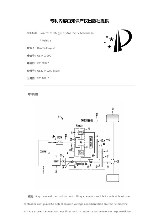
专利名称:Control Strategy For An Electric Machine InA Vehicle发明人:Rimma Isayeva申请号:US14039901申请日:20130927公开号:US20140277882A1公开日:20140918专利内容由知识产权出版社提供专利附图:摘要:A system and method for controlling an electric vehicle include at least one controller configured to detect an over-voltage condition when an electric-machine voltage exceeds an over-voltage threshold. In response to the over-voltage condition,the electric machine and a variable voltage controller (VVC) are disabled. Upon determining the electric-machine voltage is decreased to at least a second threshold being less than the over-voltage threshold, the controller is configured to set the VVC to a limited-operation mode. Upon determining the electric-machine voltage is decreased to at least a third threshold being less than the second threshold and the over-voltage threshold, the controller is configured to re-enable the electric machine and set the VVC to a normal-operation mode. The limited operation-mode enables the vehicle to maintain vehicle propulsion during the drive-cycle as the electric machine is recovered from a transient condition causing the over-voltage condition.申请人:Ford Global Technologies, LLC地址:Dearborn MI US国籍:US更多信息请下载全文后查看。
基于最优化能量管理策略的混合动力系统参数优化

基于最优化能量管理策略的混合动力系统参数优化王喜明【摘要】以插电式混合动力客车(PHB)为研究对象,应用Isight构建PHB混合动力系统集成优化平台,并设计组合优化算法.基于优化结果,确定PHB混合动力系统参数,车辆燃油经济性提高约4.4%.【期刊名称】《客车技术与研究》【年(卷),期】2018(040)004【总页数】3页(P11-13)【关键词】混合动力系统;参数优化;能量管理策略【作者】王喜明【作者单位】厦门金龙联合汽车工业有限公司,福建厦门 361023【正文语种】中文【中图分类】U464.9+3目前,关于混合动力车辆动力系统参数优化的研究大多集中在各种优化方法上,并且是基于功能性的能量管理策略进行的[1-3]。
但是,对混合动力车辆来说,动力系统参数、能量管理策略、目标工况对车辆性能的影响彼此之间是相互耦合的[4-6]。
所以,基于同一功能性能量管理策略对不同动力系统组合方案的性能评价是不公平的,也是不合理的。
为保证对每一动力系统组合方案性能的公平评价,本文提出基于最优化能量管理策略的混合动力系统参数优化方法,借助专业平台Isight对PHB混合动力系统参数进行优化研究。
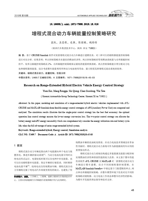
1 PHB混合动力系统参数优化本文PHB采用单轴串并联构型(如图1所示),混合动力系统由发动机、ISG电机、离合器和主驱动电机构成,通过离合器的分离与结合来实现串联和并联模式的切换。
图1 单轴串并联混合动力系统构型1.1 优化变量及约束条件PHB动力电池组的容量因受车辆设计指标所限,此外因单轴串并联混合动力系统结构对ISG电机的特殊性要求,本文只对发动机额定功率Pe,r、主驱动电机峰值功率PTM,m和主减速比i0进行优化,如式(1)所述。
将优化变量的原始值上下浮动20%作为上下限值,优化变量的相应取值区间分别是[113.6,170.4],[128,192]和[5.10,7.64]。
在PHB动力系统参数优化过程中,以车辆动力性指标和动力电池组SOC终值为约束条件,分别为:最高车速≥70 km/h,0~50 km/h加速时间≤20 s,15 km/h爬坡度指标≥12%,动力电池组SOC终值落在[0.28,0.35]内。
The State of the Art of Electric and Hybrid Vehicles

The State of the Art of Electric and Hybrid VehiclesC.C.CHAN,FELLOW,IEEEInvited PaperIn a world where environment protection and energy conser-vation are growing concerns,the development of electric vehicles (EV)and hybrid electric vehicles(HEV)has taken on an acceler-ated pace.The dream of having commercially viable EVs and HEVs is becoming a reality.EVs and HEVs are gradually available in the market.This paper will provide an overview of the present status of electric and hybrid vehicles worldwide and their state of the art, with emphasis on the engineering philosophy and key technologies. The importance of the integration of technologies of automobile, electric motor drive,electronics,energy storage,and controls and also the importance of the integration of society strength from gov-ernment,industry,research institutions,electric power utilities,and transportation authorities are addressed.The challenge of EV com-mercialization is discussed.Keywords—Electric and hybrid vehicles,electric drives,electric propulsion.I.I NTRODUCTIONElectric vehicle(EV)is a road vehicle which involves with electric propulsion.With this broad definition in mind,EVs may include battery electric vehicles(BEVs),hybrid elec-tric vehicles(HEVs),and fuel-cell electric vehicles(FCEVs). EV is a multidisciplinary subject which covers broad and complex aspects.However,it has core technologies,namely, chassis and body technology,propulsion technology,and en-ergy source technology.It is a tough task to write a survey paper on this multidisciplinary subject.Although this paper is written based on BEV,it also addresses the major issues of emerging HEV and FCEV.The paper begins with reviewing the status of BEV and HEV,then focusing on the engineering philosophy of EV development.Subsequent to the illustra-tion of the configurations of both BEV and HEV,it discusses Manuscript received April11,2001;revised August10,2001.This paper was supported by the Hong Kong Research Grant Council under Grant HKU 7035/97E.The author is with the Department of Electrical and Electronic Engi-neering,the University of Hong Kong,Hong Kong.Publisher Item Identifier S0018-9219(02)01129-5.in detail the major technologies,namely,the propulsion tech-nology,energy source technology,and infrastructure tech-nology.Finally,the commercialization aspects are discussed. The conclusion summarizes the state of the art and the chal-lenges of BEV,HEV,and FCEV.Today,BEV,HEV,and FCEV are in different stages of development,facing different challenges and requiring dif-ferent strategies.In order to assist the reader’s appreciation of the features and issues of these vehicles before reading the whole text,the major characteristics of these three types of vehicles are given in Table1.It can be seen that the crit-ical issue of BEV is the battery.Therefore,BEV is mainly suitable for small EV for short-range low-speed community transportation,which requires only smaller battery size.HEV can meet consumers’meet,but cost is the major issue.FCEV has long-term potential for future mainstream vehicles.How-ever,the technology is still in the early development stage be-cause its cost and refueling system are the major concerns. II.W HY E LECTRIC V EHICLES?Let us begin with the investigation of the growth of popu-lation and vehicles,as shown in Fig.1.In the next50years, the global population will increase from6billion to10bil-lion and the number of vehicles will increase from700mil-lion to2.5billion.If all these vehicles are propelled by in-ternal combustion engines(ICEs),where will the oil come from?Where should the emissions be disseminated?Would the sky be permanently grey?The gloomy answers to these questions compel people to strive for sustainable road trans-portation for the21st century[1],[2].In a world where environmental protection and energy conservation are growing concerns,the development of EV technology has taken on an accelerated pace to fulfill these needs.Concerning the environment,EVs can provide emission-free urban transportation.Even taking into account the emissions from the power plants needed to fuel the vehicles,the use of EVs can still significantly reduce global air pollution.From the energy aspect,EVs can offer a secure,0018-9219/02$17.00©2002IEEEPROCEEDINGS OF THE IEEE,VOL.90,NO.2,FEBRUARY2002247Table 1Characteristics of BEV ,HEV ,andFCEV(a)(b)Fig.1.Growth of population and vehicles.comprehensive,and balanced energy option that is efficient and environmental friendliness,such as the utilization of various kinds of the renewable energies.Therefore,EVswill have the potential to have a great impact on energy,environment and transportation as well as hi-tech promotion,new industry creation,and economic development.III.P AST ,P RESENT ,AND F UTURE OF EV S A.Past Years DevelopmentEV was invented in 1834.During the last decade of the 19th century,a number of companies produced EVs in America,Britain,and France.Fig.2shows the London Electric Cab Company’s taxi.Due to the limitations associ-ated with the batteries and the rapid advancement of internal combustion engine vehicles (ICEVs),EVs have almost vanished from the scene since 1930.In the early 1970s,some countries,compelled by the en-ergy crisis,started the rekindling of interests in EVs.In 1976,the USA launched the Electric and Hybrid Vehicle Research,Development,and Demonstration Act,Public Law 94–413.At that time,the main question to be answered was “Can EVs do the job in our modern society?”although EVs did work well in the late 1800s and early 1900s.The develop-ment of EVs over the years has answered the above ques-tion—yes.For example,an experimental EV in 1968racing from the California Institute of Technology (Caltech)to the Massachusetts Institute of Technology (MIT)suffered from failures in virtually every critical component,whereas a com-mercially built EV in 1998running from Los Angeles to De-troit exhibited a success with no component failures.Within the 1970s,EVs were still in research and development stage and most of them were conversion of ICEVs.Today,major automobile manufacturers are offering EVs for sale or lease.Most of them are the purpose-built EV ,not conversion EV [1],[16]B.Present Major IssuesAt present,the major driving force for EVs is the envi-ronment issue,such as mandate by California rule,rather248PROCEEDINGS OF THE IEEE,VOL.90,NO.2,FEBRUARY 2002Fig.2.London electric cab company’s taxi(courtesy of Scientific American supplement;photo courtesy of History of the Electric Automobile by Ernest H.Wakefied).than the previous energy issue.Thus,the main question to be answered becomes“Can EVs be made affordable?”The major factors that make EV affordable are the range and cost.To tackle the range,the development of advanced batteries such as nickel-metal hydride(Ni-MH),zinc/air (Zn/Air),and lithium-ion(Li-Ion)are in progress.However, since both specific energy and energy density of batteries are much lower than that of gasoline,the development of fuel cells(FCs)for EVs has taken on an accelerated pace in recent years.Meanwhile,the development of commercial HEVs is also going on rapidly.HEVs essentially improve the range and performance of EVs at higher complexity and cost because of the additional energy source,engine, and other accessories.To tackle the cost,efforts are being made to improve various EV subsystems,such as electric motors,power converters,electronic controllers,energy management units,battery chargers,batteries,and other EV auxiliaries,as well as EV system-level integration and optimization.C.Development TrendsIn order to see the development trends of various EV aspects,a survey has been made with respect to the number of papers published on various topics in leading EV related international conferences from1984to2001.With regard to propulsion system,it was observed that the research papers on induction motor(IM)drives and permanent magnet (PM)motor drives are highly dominant,whereas those on direct current(DC)motor drives are dropping while those on switched reluctance(SR)motor drives are still in a crawling stage.With regard to the development trend of various energy sources,including lead-acid(LA)batteries ,nickel-based(NB)batteries,lithium-based(LB)batteries, FCs,and capacitors/flywheels(CFs).The number of papers published in LB,FC,and CF are becoming more and more attractive,though LA and NB are still undergoing continual improvement.With regard to the configurations of EVs, it was observed that the conversion EV is becoming less attractive than the purpose-built EV,while the HEV is of growing interest for the coming EV markets.It was also observed that EVs are on the verge of commercialization, since more and more papers were published on the topics of demonstration as well as standardization and marketing of EVs.In the next few decades,it is anticipated that both EVs and HEVs will be commercialized and they will have their market shares.EVs will be well accepted by some niche markets,namely,the users for community transportation,the places where electricity is cheap,and ease of access and the places with zero-emission mandate.On the other hand, HEVs will have a niche market for those users desiring long driving ranges.The ultimate penetration of EVs and HEVs will mainly depend on their respective costs.The commer-cialization of FCEVs will be accelerated in later decades, since they have the greatest potential to deliver the same range and performance as our ICEVs,but now it is still in the development stage.In summary,electric propulsion and energy sources will still be the key technologies to be addressed and EVs and HEVs will still be coexistent,while energy,environment,and economy will still be the key issues for EV commercializa-tion.Fig.3illustrates the development trends of EVs and HEVs.It should be noted that some core technologies canCHAN:THE STATE OF THE ART OF ELECTRIC AND HYBRID VEHICLES249Fig.3.Development trends of EVs and HEVs(courtesy of EV AA).be shared among ICEVs,EVs,and HEVs.Our ultimate goal is the use of clean,efficient,and intelligent energy to achieve sustainable transportation system for the21st century.IV.P RESENT S TATUSAfter many years of development,EV technologies are becoming mature.Many advanced technologies are em-ployed to extend the driving range and reduce the cost.For example,the use of advanced IM drives and PM brushless motor drives to improve the electric propulsion system, the employment of advanced valve-regulated lead-acid (VRLA)battery,Ni-MH battery,Li-Ion battery,FCs,and ultracapacitors to improve the EV energy source,application of light body technology with light,but rigid material, low-drag coefficient body to reduce the aerodynamic resis-tance and low rolling resistance tires to reducing running resistance at low and medium driving speed,as well as the adoption of advanced charging,power steering,or variable temperature seats to enhance the EV auxiliaries.In the following paragraphs,some of the recently developed EV, HEV,and FCEV are illustrated with the intention to show the achievable technology,despite particular vehicle model. For example,EV1has been discontinued and some models are for demonstration purpose only,i.e.,NECAR5and Ford P2000.These typical vehicles have been carefully chosen to represent the state of the art.GM EV1and Nissan Altra EV represent advanced BEV using different types of motor and battery.Ford2000P and NECAR5represent the development stage of FCEV,Toyota Prius and Honda Insight represent the commercialization of HEV,Luciole and HKU200represent showcase BEV,and Reva represents commercially produced low-cost BEV.Showcasing the most advanced propulsion system, the1997two-seater GM EV1is shown in Fig.4.It had a front-wheel drive that adopted a102-kW three-phase IM and a single-speed transaxle with dual-reduction of 10.946:1.It contained26-module312-V VRLA batteries that were inductively charged by a6.6-kW offboard charger or a1.2-kW onboard charger.This EV1could offer an axle torque of1640Nm from zero to7000rpm and a propulsion power of102kW from7000to14000rpm,leading to achieve a top speed of128km/h(electronically limited)and an acceleration from zero to96km/h in less than9s.For city driving,it could provide a range of112km per charge, whereas on highway operation,it offered144km per charge. In1999,the EV1adopted nickel-metal hybrid batteries as an optional equipment,hence,reaching220km per charge. Fig.5shows the1997four-seater Altra EV,which was the flagship of Nissan.It used a62-kW PM brushless motor, which weighed only39kg,the highest power-to-weight ratio (1.6kW/kg)for any EV motor available.Making use of max-imum efficiency control,the total efficiency of the propulsion system was more than89%.Power came from the cobalt-based Li-Ion batteries,which had a specific energy of90 Wh/kg,a specific power of300W/kg,and a long cycle life of about1200recharges.This battery pack could be charged up by an onboard inductive charging system within five hours. It could achieve a top speed of120km/h and a range of 192km for city driving.In1999,the Altra adopted the man-ganese-based Li-Ion batteries to further increase both spe-cific energy and specific power to91Wh/kg and350W/kg, respectively.The Ford P2000symbolized the dedication of Ford in the development of FCEVs.Fig.6shows this four-door sedan,250PROCEEDINGS OF THE IEEE,VOL.90,NO.2,FEBRUARY2002Fig.4.GM EV1(photo courtesy of GeneralMotors).Fig.5.Nissan Altra EV(photo courtesy ofNissan).Fig.6.Ford P2000(photo courtesy of Ford Motor Company).which was launched in the year2000.It was powered by the Ford’s Th!nk FC system,namely,the proton exchange membrane(PEM)FCs,which was fuelled by compressed hy-drogen gas(CHG)stored at25MPa and oxygen gas simply from the air.It adopted a three-phase IM,offering a peak power of67kW,a peak torque of190Nm,and a peak ef-ficiency of91%.With the curb weight of1514kg,the P2000 could achieve a top speed of128km/h and a driving range of 160km per charge.Daimler-Benz,now DaimlerChrysler,presented its first methanol-fuelled FCEV in1997—the NECAR3.It used PEM FCs to generate a power of50kW for propulsion. The hydrogen fuel was directly extracted from methanol via a mini reformer,thus bypassing the problem of having compressed gas canisters onboard the vehicle.The FCs were stored beneath the floor,while the reformer,methanol tank, and control systems were located in the boot.Based on this first generation methanol-fuelled FC propulsion system,CHAN:THE STATE OF THE ART OF ELECTRIC AND HYBRID VEHICLES251Fig.7.DaimlerChrysler NECAR5(photo courtesy ofDaimlerChrysler). Fig.8.Toyota Prius(photo courtesy of Toyota).the NECAR3could travel over400km on38L of liquid methanol.As shown in Fig.7,the NECAR5launched in 2000was the technological successor of the NECAR3, while reducing the size of the drive system by half and the weight of the vehicle by300kg.It also boosted up the power to75kW to reach speeds over150km/h.The world’s first mass-production HEV was the Toyota Prius,as shown in Fig.8.Its motive power was sourced from both a four-cylinder ICE(52kW at4500rpm)and a PM brushless motor(33kW at1040–5600rpm).Since it was an ICE-heavy HEV,a power split device,namely,the plane-tary gear,sent part of the ICE power to the wheels and part to a generator.The generated electrical energy could supply the electric motor to increase the motive power or could be stored in the38-module nickel-metal hybrid batteries.The Prius could offer a top speed of160km/h,an acceleration from zero to96km/h in12.7s,and a fuel economy of20 km/l for combined city and highway operation.Both of its fuel economy and exhaust emissions were much better than that of any conventional ICEVs.The Honda Insight,shown in Fig.9,went on sale in December2000.It employed an ICE-heavy hybrid system, combining a three-cylinder ICE(50kW at5700rpm)and a PM synchronous motor(10kW at3000rpm).The electric motor was powered by a144-V Ni-MH battery pack, which was recharged by regenerative braking during normal cruising and downhill driving.The Insight was claimed to be the most fuel-efficient HEV with the fuel economy of26–30 km/l.Also,it satisfied the stringent ultra low-emission vehicle(ULEV)standard in California.To simultaneously address the problems of air pollution, wasteful energy consumption,and traffic safety,the Na-252PROCEEDINGS OF THE IEEE,VOL.90,NO.2,FEBRUARY2002Fig.9.Honda Insight(photo courtesy ofHonda). Fig.10.NIES Luciole(photo courtesy of NIES,Japan).tional Institute for Environmental Studies(NIES)in Japan presented a high-performance lightweight EV,namely,the Luciole(formerly called Eco-Vehicle)in1996for conve-nient city commuting.As shown in Fig.10,it adopted a tandem two-seater layout so that the seats could be kept comfortable and the safety in side crushes could be im-proved by thickening the doors.It was rear-wheel drive, which was powered by two inwheel PM brushless motors with the total output of72kW and154Nm.The battery pack contained224-V VRLA batteries,mounted inside the square holes of the purpose-built chassis.The battery pack could be charged up by normal charging within five hours, by fast charging within fifteen minutes or even partially charged by solar charging.The Luciole could achieve a top speed of130km/h,a range on the Japan10.15Mode driving cycle of130km,and an acceleration from zero to 40km/h in3.9s.Fig.11shows an EV,the U2001,which was developed by the University of Hong Kong(HKU)in1993.It was a four-seater EV,which adopted a45-kW PM hybrid motor and a264-V nickel-cadmium(Ni-Cd)battery pack.This specially designed EV motor could offer high efficiencies over a wide operating range.It also incorporated a number of advanced EV technologies,such as the adoption of thermoelectric variable temperature seats to minimize the energy used for air-conditioning,the use of an audio nav-igation system to facilitate safe and user-friendly driving, and the use of an intelligent energy management system (EMS)to optimize the energy flow within the vehicle.The U2001could offer a top speed of110km/h,an acceleration from zero to48km/h in6.3s,and a range of176km at 88-km/h operation.Apart from the USA,Europe,and Japan,India also plays an active role to commercialize EVs.Fig.12shows aCHAN:THE STATE OF THE ART OF ELECTRIC AND HYBRID VEHICLES253Fig.11.HKUU2001.Fig.12.Reva EV(photo courtesy of Reva Electric Car Company).two-door hatchback EV,the Reva EV,which was launched in the year2001and would be India’s first mass-produced EV.It adopted a separately excited DC motor(70Nm,13 kW peak)and a48-V tubular LA battery pack.Its onboard charger(220V,2.2kW)could provide80%charge within3 h and100%within6h.With the curb weight of650kg,the Reva EV could achieve a top speed of65km/h and a range of80km per charge.The most attractive feature was its incredibly low initial and running costs—the exfactory cost is about5000U.S.dollars and the running cost is less than one U.S.cent per kilometer.The major means of reducing the cost of this EV includes the system optimization and integration,low-cost local components,low-cost tooling, and simple automation.It can be seen from Table2that the sale and lease of EVs in USA from1996to2000were not successful;the major reason was that their cost was too expensive and their driving range did not fully satisfy the users’need(Table3).254PROCEEDINGS OF THE IEEE,VOL.90,NO.2,FEBRUARY2002Table 2EVs Sold/Leased in the USA1996–2000Table 3Key Data of ModernEVsV .E NGINEERING P HILOSOPHY OF EV D EVELOPMENT A.EV ConceptAlthough the EV was around before the turn of the 20th century,the modern EV is a completely new machine that is totally different from the classical EV .It is not only a trans-portation vehicle,but also a new type of electric equipment.The modern EV concept is summarized as follows.1)The EV is a road vehicle based on modern electric propulsion that consists of the electric motor,power converter,and energy source and it has its own distinct characteristics.2)The EV is not just a car,but a new system for our so-ciety,realizing clean and efficient road transportation.3)EV users’expectations must be studied and,hence,appropriate education must be conducted.The system architecture of EVs has its own distinct features that may differ from that of ICEVs,similar to the fact that the system architecture of quartz-based electronic watches is very different from that of spring-based mechan-ical watches.In short,their appearances are very similar,whereas their principles are very different.The unique features of EVs must be fully appreciated.B.EV Engineering PhilosophyThe EV engineering philosophy essentially is the integra-tion of automobile engineering and electrical engineering.Thus,system integration and optimization are prime con-siderations to achieve good EV performance at affordable cost.Since the characteristics of electric propulsion arefundamentally different from those of engine propulsion,a novel design approach is essential for EV engineering.Moreover,advanced energy sources and intelligent energy management are key factors to enable EVs competing with ICEVs.Of course,the overall cost effectiveness is the fundamental factor for the marketability of EVs.The design approach of modern EVs should include state-of-the-art technologies from automobile engineering,electrical and electronic engineering,and chemical engi-neering,adopt unique designs particularly suitable for EVs,and develop special manufacturing techniques particularly suitable for EVs.Every effort should be made to optimize the energy utilization of EVs.The following points are those typical considerations for EV design.1)Identify the niche market and environment.2)Determine the technical specifications including the driving cycle.3)Determine the infrastructure required including the recycling of batteries.4)Determine the overall system configuration—BEV ,HEV ,or FCEV configurations.5)Determine the chassis and body.6)Determine the energy source—generation or storage,single or hybrid.7)Determine the propulsion system—motor,converter,and transmission types,single or multiple motors,gearless or geared,mounting methods,and ICE sys-tems in case of an HEV .8)Determine the specifications of electric propulsion (power,torque,speed)and energy source (capacity,CHAN:THE STATE OF THE ART OF ELECTRIC AND HYBRID VEHICLES255(a)(b)Fig.13.Torque-speed requirements of typical driving cycles.voltage,current)according to various driving cycles;for example,Fig.13shows that the torque-speed requirement of the Federal Urban Driving Schedule (FUDS)is very different from that of the Federal Highway Driving Schedule (FHDS).In Fig.13,the density of dots represents the frequency of operating condition.Hence,in FUDS,the powertrain often operates at low speed and high torque,while in FHDS,it operates at a high-speed low-torque profile.9)Adopt intelligent EMS.10)Analyze the interaction of EV subsystems by using the quality function matrix as shown in Fig.14,hence,understanding the degree of interaction that affects the cost,performance,and safety.11)Optimize the efficiency of the motor drive according to the selected driving pattern and operating condi-tions.12)Optimize the overall system using computer simula-tion.C.Key EV TechnologyThe key technologies of EVs include automotive technology,electrical technology,electronic technology,information technology,and chemical technology.Although the energy source is the most crucial area,body design,electric propulsion,energy management,and system opti-mization are equally important.In fact,the integration of all these areas is the key to success.For ease of reading,only body design,energy management,and system optimization technologies are discussed in this section,while the major technologies of electric propulsion and energy source will be discussed separately in the subsequent sections.1)Body Design:There are two basic approaches for pro-ducing EVs—either conversion or purpose-built.For the con-version EV ,the engine and associated equipment of an ex-isting ICEV are replaced by the electric motor,power con-verter,and battery.This offers some economy for a small volume production because the existing ICEV chassis can be utilized.However,in most conversions,the resulting EV suffers from a greater curb weight,a higher centre of gravity and an unbalanced weight distribution.Therefore,this ap-proach is gradually fading out.At present,the modern EVs are mostly purpose-built,sometimes called groundup design.This purpose-built EV takes the definite advantage over the conversion ones because they allow the engineers having the flexibility to coordinate and integrate various EV subsystems so that they can work together efficiently [17].256PROCEEDINGS OF THE IEEE,VOL.90,NO.2,FEBRUARY 2002Fig.14.Interactions among EV sybsystems.There are some design concepts for purpose-built EVs so that the overall performances such as range,gradeability,ac-celeration,and top speed can be improved.These concepts include the consistent weight-saving design,low drag co-efficient body design,and low rolling resistance concept. First,the vehicle weight directly affects the performance of EVs,especially the range and gradeability.To reduce the curb weight,the use of lightweight materials such as alu-minum and composite material for the body and chassis can be adopted.Second,low drag coefficient body design can ef-fectively reduce the vehicle aerodynamic resistance,which has a significant effect on extending the range of EVs in highway driving or cruising.In general,the aerodynamic resistance can be reduced by tapering front and rear ends, adopting undercover and flat underfloor design,optimizing airflow around the front and rear windows,using rear spats, providing airflow streaks along the front and rear tires,and employing slanted front nose design.Third,low rolling re-sistance tires are particularly effective in reducing running resistance at low and medium driving speeds and play an im-portant role in extending the range of EVs in city driving. This can be achieved through the use of a newly developed blended tire polymer,together with an increase in tire pres-sure.2)Energy Management:Compared with ICEVs,EVs offer a relatively short driving range.Thus,in order to maximize the utilization of onboard stored energy,an intelligent EMS needs to be adopted.Making use of sensory inputs from various EV subsystems,including sensors for temperatures of outside and inside air,current,and voltage of the energy source during charging and discharging, current and voltage of the electric motor,vehicle speed,and acceleration as well as external climate and environment, the EMS can realize the following functions.1)Optimize the system energy flow.2)Predict the remaining available energy and hence theresidual driving range.3)Suggest more efficient driving behavior.4)Direct regenerative energy from braking to receptiveenergy sources such as batteries.5)Modulate temperature control in response to externalclimate.6)Adjust lighting brightness in response to external en-vironment.7)Propose a suitable battery charging algorithm.8)Analyze the operation history of the energy source,especially the battery.9)Diagnose any incorrect operation or defective compo-nents of the energy source.When the EMS is coupled with a navigation system,it can plan energy efficient routes,locate charging facilities for extended trips,and modify range predictions on the basis of traffic conditions.In summary,the EMS has the distinct features of integrated multifunctions,flexibility,and adapt-ability(just like the brain of EVs)such that the limited on-board energy can be used wisely.3)System Optimization:As mentioned before,the EV system has a complex architecture that contains multidisci-plinary technologies.Since the EV performance can be af-fected by many multidisciplinary interrelated factors,com-puter simulation is the most important technology to carry out the optimization for performance improvement and cost reduction.Also,EV simulation can help those manufacturers to minimize prototyping cost and time and to provide rapid concept evaluation.Since the whole EV system consists of various subsystems clustered together by mechanical,elec-trical,control,and thermal links,the simulation should be based on the concept of mixed-signal simulation.Hence,the system optimization can be carried out in the system level in which there are many tradeoffs among various subsystem criteria.Generally,numerous iterative processes are involved for the preferred system criteria[1].In summary,the system-level simulation and optimization of EVs should consider the following key issues.1)As the interactions among various subsystems greatlyaffect the performance of EVs,the significance ofthose interactions should be analyzed and taken intoaccount.2)As the model accuracy is usually coherent withthe model complexity but may be contradictory tothe model usability,tradeoffs among the accuracy,complexity,and usability as well as simulation timeshould be considered.3)As the system voltage generally causes contradictoryissues for EV design,including the battery weight(higher voltage requires higher number of batterymodules in series,hence more weight for the batterycase),motor drive voltage and current ratings,ac-celeration performance,driving range and safety,itshould be optimized on the system level.4)In order to increase the driving range,multiple energysources may be adopted for modern EVs.The corre-sponding combination and hybridization ratio shouldbe optimized on the basis of the vehicle performanceand cost.CHAN:THE STATE OF THE ART OF ELECTRIC AND HYBRID VEHICLES257。
增程式混合动力车辆能量控制策略研究
10.16638/ki.1671-7988.2019.18.016增程式混合动力车辆能量控制策略研究袁凯,孟蓉歌,史强,陈国栋,魏特特(陕西汽车集团技术中心,陕西西安710021)摘要:基于CRUISE/Simulink软件对某款增程式混合动力车辆进行建模仿真,对三种可行的増程器能量控制策略进行对比分析。
结果表明:单点控制策略具有最佳的燃油经济性,两点控制策略的等效燃油消耗量与功率跟随控制持平,较单点跟随控制策略高1%。
功率跟随控制策略保证最低的能量转换损耗,两点控制策略能合理分配动力电池和増程器的能量,综合考虑整车能量利用率和动力电池使用寿命,最大程度发挥增程式混动系统的优势。
关键词:增程式混合动力;能量控制;仿真分析中图分类号:U469.7文献标识码:A 文章编号:1671-7988(2019)18-45-03Research on Range-Extended Hybrid Electric Vehicle Energy Control StrategyYuan Kai, Meng Rongge, Shi Qiang, Chen Guodong, Wei Tete( Shaanxi Automobile Group Technology Center, Shaanxi Xi’an 710021 )Abstract:In this paper, modeling and simulation of a range-extended hybrid electric vehicleis implemented with A VL- CRUISE and MA TLAB/Simulink,three feasible energy control strategies of APU(Auxiliary Power Unit) are compared and analyzed. The simulation results illustrate that:the single-point control strategy has the best fuel economy; the optimal operation line control strategy ensures the lowest energy conversion loss. The two-point control strategy can allocate the battery energy andAPU energy reasonably,which can comprehensively consider the energy utilization rate and battery cycle life, takes the full advantage of series range-extended hybrid system.Keywords: Range-extended hybrid; Energy control; Simulation analysisCLC NO.: U469.7 Document Code: A Article ID: 1671-7988(2019)18-45-031 前言增程式混合动力车辆是指由两个电能源向单个电动力装置供电,推进车辆的驱动系统[1]。
基于模型的混合动力电动汽车系统的设计.
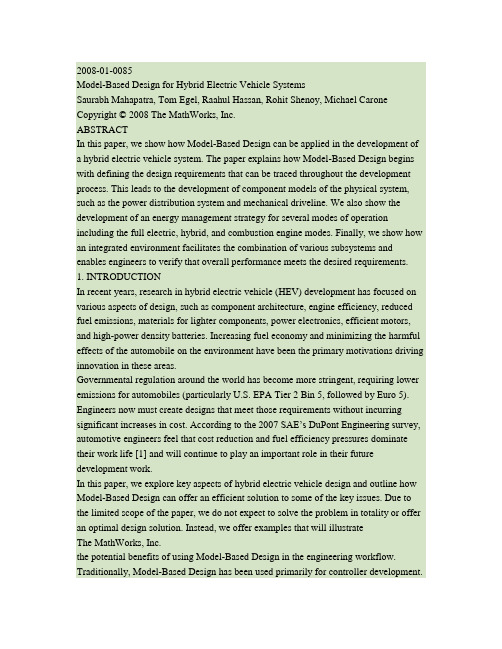
2008-01-0085Model-Based Design for Hybrid Electric Vehicle SystemsSaurabh Mahapatra, Tom Egel, Raahul Hassan, Rohit Shenoy, Michael Carone Copyright © 2008 The MathWorks, Inc.ABSTRACTIn this paper, we show how Model-Based Design can be applied in the development of a hybrid electric vehicle system. The paper explains how Model-Based Design begins with defining the design requirements that can be traced throughout the development process. This leads to the development of component models of the physical system, such as the power distribution system and mechanical driveline. We also show the development of an energy management strategy for several modes of operation including the full electric, hybrid, and combustion engine modes. Finally, we show how an integrated environment facilitates the combination of various subsystems and enables engineers to verify that overall performance meets the desired requirements. 1. INTRODUCTIONIn recent years, research in hybrid electric vehicle (HEV) development has focused on various aspects of design, such as component architecture, engine efficiency, reduced fuel emissions, materials for lighter components, power electronics, efficient motors, and high-power density batteries. Increasing fuel economy and minimizing the harmful effects of the automobile on the environment have been the primary motivations driving innovation in these areas.Governmental regulation around the world has become more stringent, requiring lower emissions for automobiles (particularly U.S. EPA Tier 2 Bin 5, followed by Euro 5). Engineers now must create designs that meet those requirements without incurring significant increases in cost. According to the 2007 SAE’s DuPont Engineering survey, automotive engineers feel that cost reduction and fuel efficiency pressures dominate their work life [1] and will continue to play an important role in their future development work.In this paper, we explore key aspects of hybrid electric vehicle design and outline how Model-Based Design can offer an efficient solution to some of the key issues. Due to the limited scope of the paper, we do not expect to solve the problem in totality or offer an optimal design solution. Instead, we offer examples that will illustrateThe MathWorks, Inc.the potential benefits of using Model-Based Design in the engineering workflow. Traditionally, Model-Based Design has been used primarily for controller development.One of the goals of this paper is to show how Model-Based Design can be used throughout the entire system design process.In section 2, we offer a short primer on HEVs and the various aspects of the design. Section 3 is devoted to Model-Based Design and the applicability of the approach to HEV development. Sections 4, 5, and 6 will focus on examples of using Model-Based Design in a typical HEV design.2. HYBRID ELECTRIC VEHICLE DESIGNCONCEPTA block diagram of one possible hybrid electric vehicle architecture is shown in Figure1. The arrows represent possible power flows. Designs can also include a generator that is placed between the power splitter and the battery allowing excess energy to flow back into thebattery.Figure 1: The main components of a hybrid electric vehicle.Conceptually, the hybrid electric vehicle has characteristics of both the electric vehicle and the ICE (Internal Combustion Engine) vehicle. At low speeds, it operates as an electric vehicle with the battery supplying the drive power. At higher speeds, the engine and the battery work together to meet the drive power demand. The sharing and the distribution of power between thesetwo sources are key determinants of fuel efficiency. Note that there are many other possible designs given the many ways that power sources can work together to meet total demand.DESIGN CONSIDERATIONSThe key issues in HEV design [2] are typical of classical engineering problems that involve multilayer, multidomain complexity with tradeoffs. Here, we discuss briefly the key aspects of the component design: very similar to those of a traditional ICE. Engines used in an HEV are typically smaller than that of a conventional vehicle of the same size and the size selected will depend on the total power needs of the vehicle.design are capacity, discharge characteristics and safety. Traditionally, a higher capacity is associated with increase in size and weight. Discharge characteristics determine the dynamic response of electrical components to extract or supply energy to the battery. motors, AC induction motors, or Permanent Magnet Synchronous Motors (PMSM). Each motor has advantages and disadvantages that determine its suitability for a particular application. In this list, the PMSM has the highest power density and the DC motor has the lowest. [3].splitter that allows power flows from the two power sources to the driveshaft. The engine is typically connected to the sun gear while the motor is connected to the ring gear.aerodynamic drag interactions with weight and gradability factors accounted for in the equations.process of the hybrid powertrain is to study the maximum torque demand of the vehicle as a function of the vehicle speed. A typical graph is shown in Figure 2. Ratings of the motor and the engine are determined iteratively to satisfy performance criteria and constraints. The acceleration capabilities are determined by the peak power output of the motor while the engine delivers the power for cruising at rated velocity, assuming that the battery energy is limited. Power sources are coupled to supply power by the power-splitter, and the gear ratio of the power-splitter is determined in tandem. The next steps include developing efficient management strategies for these power sources to optimize fuel economy and designing the controllers. The final steps focus on optimizing the performance of this system under a variety of operating conditions.Figure 2: Maximum torque demand as a function of vehicle tire speed.3. MODEL-BASED DESIGN OF AN HEVMOTIVATIONIn this section, we outline some of the challenges associated with HEV design and explain the motivation for using Model-Based Design as a viable approach for solving this problem.of an HEV design problem is reflected in the large number of variables involved and the complex nonlinear relationships between them. Analytical solutions to this problem require advanced modeling capabilities and robust computational methods.set of requirements to meet the vehicle performance and functionality goals. Requirements refinement proceeds iteratively and depends on implementation costs and equipment availability.conceptualize the operation of the system’s various components and understand the complex interactions between them. This often requires experimentation with various system topologies. For example, studies may include comparing a series configuration with a parallel configuration. Because the goal is a better understanding of the overallsystem behavior, the models must include the appropriate level of detail. system level to a more detailed implementation, engineers elaborate the subsystem models to realize the complete detailed system model. This can be accomplished by replacing each initial model of a component with the detailed model and observing the effects on performance. Completing this process andrealizing a detailed model of the system requires robust algorithms for solving complex mathematics in a timely fashion.and mechanical components. Typically these components are designed by domain specialists. To speed development, these engineers need to effectively communicate and exchange design ideas with a minimum of ambiguity.typical HEV design is to increase the fuel efficiency of the vehicle while maintaining performance demands. Intuitively, one can look at this problem as finding the optimal use of the power sources as a function of the vehicle internal states, inputs, and outputs satisfying various constraints. This translates to the requirement for switching between various operational “power modes” of the vehicle as a func tion of the states, inputs, and measured outputs [4]. In a true environment for Model-Based Design the power management algorithms co-exist with the physical system models.complexity of the various subsystems, HEV controller design is typically a complex task. A variety of control algorithms specific to each subsystem may be required. For example, the controller that manages the frequency of the input voltage to the synchronous motor will be different from the simple control used for torque control of the same motor. Typically, this will manifest itself as a multistage, multiloop control problem. Successful implementation of the controllers requires deployment of these algorithms on processors that are integrated while interfacing with the physical plant. testing ensures that it continues to meet requirements. Detection of errors early in the process helps reduce costs associated with faulty designs. As design errors trickle down the various workflow stages the costs associated with correcting them increase rapidly[5]. The ability to continually verify and validate that requirements are being satisfied isa key aspect of Model-Based Design.A software development environment for Model-Based Design must be able to address the aforementioned challenges. Additionally, a single integrated environment facilitates model sharing between team members. The ability to create models at various levels of abstraction is needed to optimize the simulation time. A mechanism for accelerating the simulation as the complexity increases will also be important. PROCESS OF MODEL-BASED DESIGNModel-Based Design can be thought of as a process of continually elaborating simulation models in order to verify the system performance. The overall goal is to ensure first pass success when building the physicalprototype. Figure 3 shows the key elements of Model-Based Design.The system model forms the “executable specification” that is used to communicate the desired system performance. This model is handed over to the various specialists who use simulation to design and further elaborate the subsystem models. These specialists refine the requirements further by adding details or modifying them. The detailed models are then integrated back into the system level realization piece by piece and verified through simulation. This goes on iteratively until a convergence to an optimal design that best meets the requirements results. During Model-Based Design, C-code generation becomes an essential tool for verifying the system model. The control algorithm model can be automatically converted to code and quickly deployed to the target processor for immediate testing. Code can also be generated for the physical system to accelerate the simulation and/or to test the controller with Hardwarein the Loop simulation.Figure 3: The key elements of Model-Based Design.4. SYSTEM LEVEL MODELING OF AN HEVIn the first stage of the HEV design, the system-level description of the system is realized. Experimentation enables the system designer to explore innovative solutions in the design space resulting in optimal architectures. Our approach has been inspired by an earlier SAE paper [6]. REQUIREMENTSIn the initial stages of the project, it is not uncommon for the specifications of subsystem components to shift. The requirements are in a preliminary form, and are based on previous designs, if available, or best engineering judgment. Requirements are refined when each of the component models is delivered to component designers for additional refinement. There are, however, certain requirements that the system architect understands fully, and can lock down. As the project moves from requirements gathering to specification, the concepts of the system architects can be included in the model. Collaboration between architects and designers leads to a much better and more complete specification. The system can be expressed as a series of separate models that are to be aggregated into an overall system model for testing. Breaking down the model into components facilitates component-based development and allows several teams to work on individual components in parallel. This kind of concurrent development was facilitated by the parallel configuration we chose for our example, in which the electrical and mechanical power sources supply power in parallel. The broad design goals were:Improve fuel efficiency to consume less than 6.5liters per 100 km (L/100 km) for the driver input profile shown in Figure 4.Cover a quarter mile in 25 seconds from rest. Attain a top speed of 193 kph.Figure 4: Driver input profile as outlined in the requirements document.These and other such requirements are typically captured in a requirements document that engineers can associate with the design models. This provides the ability to trace the requirements throughout the model, a key component of Model-Based Design. VEHICLE DYNAMICSModeling the vehicle dynamics can be a challenging task. When creating any simulation model it is important to consider only the effects that are needed to solve the problem at hand. Superfluous details in a model will only slow down the simulation while providing little or noadditional benefit. Because we are primarily interested in the drive cycle performance, we will limit our vehicle model to longitudinal dynamics only. For example, the vehicle was initially modeled as a simple inertial load on a rotating shaft connected to the drive train. ENGINEA complete engine model with a full combustion cycle is also too detailed for this application. Instead, we need a simpler model that provides the torque output for a given throttle command. Using Simulink® and SimDriveLine™, we modeled a 57kW engine with maximum power delivery at 523 radians per second, as shown in Figure5.Figure 5: Engine modeled using blocks from the SimDriveline™ library. SYNCHRONOUS MOTOR/GENERATORThe synchronous motor and generator present an interesting example of electromechanical system modeling. Standard techniques for modeling synchronous machines typically require complex analysis of equations involving electrical and mechanical domains. Because the input source to this machine drive is a DC battery and the output is AC, this would require the creation of complex machine drive and controller designs – often a significant challenge at this stage.An averaged model that mathematically relates the control voltage input with the output torque and resulting speed is a useful alternative. This simplification allows us to focus on the overall behavior of this subsystem without having to worry about the inner workings. Furthermore, we can eliminate the machine drive by simply feeding the DC voltage directly to this subsystem. With this averaged model, we only need a simple Proportional-Integral (PI) controller to ensure effective torque control. TheMotor/Generator subsystem design will be explored in more detail in the next section. POWER-SPLITTERThe power-splitter component is modeled as a simple planetary gear, as shown in Figure 6. With these building blocks, more complex gear topologies can easily be constructed and tested within the overall system model.Figure 6: Power-splitter modeled as a planetary gear with connections.POWER MANAGEMENTThe power management subsystem plays a critical role in fuel efficiency.The subsystem has three main components:• Mode logic that manages the various operatingmodes of the vehicle.• An energy computation block that computes theenergy required to be delivered by the engine, the motor, or both in response to gas pedal input at any given speed.• An engine controller that ensures the engine is theprimary source of power and provides most of the torque. The motor and generator controllers provide torque and speed control.MODE LOGICFor efficient power management, an understanding of the economics of managing the power flow in the system is required. For example, during deceleration, the kinetic energy of the wheels can be partially converted to electrical energy and stored in the batteries. This implies that the system must be able to operate in different modes to allow the most efficient use of the power sources.We used the conceptual framework shown in Figure 7 to visualize the various power management modes.Algorithm design starts with a broad understanding of the various possible operating modes of the system. In our example, we identified four modes—low speed/start, acceleration, cruising, and braking modes. For each of these modes, we determined which of the power sources should be on and which should be off.The conceptual framework of the mode logic is easily implemented as statechart. Statecharts enable the algorithm designer to communicate the logic in an intuitive, readable form.Figure 7: Mode logic conceptualized for the hybrid vehicle.The Stateflow® chart shown in Figure 8 is a realization of the conceptual framework shown in Figure 7. While very similar to the conceptual framework, the Stateflow chart has two notable differences. The “acceleration” and “cruise” states have been grouped to form the “normal” superstate, and the “low speed/start” and “normal” states have been grouped together to form the “motion” superstate. This grou ping helps organize the mode logic into a hierarchical structure that is simpler to visualize and debug.Figure 8: Mode logic modeled with Stateflow®. SYSTEM REALIZATIONAfter the HEV components have been designed, they can be assembled to form the parallel hybrid system shown in Figure9.Figure 9: System-level model of the parallel HEV.This system model can then be simulated to determine if the vehicle meets the desired performance criteria over different drive cycles. As an example, for the input to the system shown in Figure 4, the corresponding speed and the liters per 100 km (L/100 km) outputs are shown in Figure 10. Once the baseline system performance has been evaluated using the system model, we begin the process of model elaboration. In this process, we add more details to the subsystems models to make them more closely represent the actual implementation. During this process, design alternatives can be explored and decisions made based on the analysis results. This is a highly iterative process that is accelerated using Model-Based Design.5. MODEL ELABORATIONIn the model elaboration stage, the subsystem components undergo elaboration in parallel with requirements refinement.A subsystem block is an executable specification because it can be used to verify that the detailed model meets the original set of requirements.As an example, we show how the generator machine drive undergoes requirements refinement and model elaboration. We assume that the engineer responsible for themachine drive design will carry out the model elaboration of the plant and the associated controller.REQUIREMENTS REFINEMENTThe machine drive is an aggregated model of the machine and the power electronics drive. In the system level modeling phase, the key specification is the torque-speed relationship and the power loss. This information was sufficient to define an abstract model to meet the high-level conceptual requirements.Figure 10: Output speed and L/100 km metric for the averaged model.As additional design details are specified, the model must become more detailed to satisfy the subsystem requirements. For example, the generator model will need parameters such as the machine circuit equivalent values for resistance and inductance. Engineers can use this specification as the starting point towards the construction of an electric machine customized for this HEV application.In the case of the generator drive, as the machine model is elaborated from an averaged model to a full three phase synchronous machine implementation, the controller must also be elaborated. PLANT ELABORATIONThe machine model for the synchronous generator is elaborated using SimPowerSystems™ blocks that represent detailed models of power system components and drives. For this model, the electrical and mechanical parts of the machine are each represented by a second-order state-space model. Additionally, the internal flux distribution can be either sinusoidal or trapezoidal. This level of modeling detail is needed to make design decisions as the elaboration process progresses.Figure 11: Detailed PMSM model parameters.The details of this model are captured in the model parameters shown in Figure 11, which specify the effects of internal electrical and magnetic structures.CONTROL ELABORATIONThe controller used in the averaged model of the AC machine drive is a simple PI controller. In model elaboration of the synchronous machine plant, a DC battery source supplies energy to the AC synchronous machine via an inverter circuit that converts DC to AC. These changes in plant model structure and detail require appropriate changes to the controller model to handle different control inputs and implement a new strategy. For example, the power flow to the synchronous machine is controlled by the switching control of the three phase inverter circuit. This added complexity was not present in the initial model of the machine drive because we focused on its behavior rather than its structure. We implemented a sophisticated control strategy, shown in Figure 12, that included cascaded speed and vector controllers [7]. The controllers were developed using Simulink® Control Design™ to satisfy stability and performance requirements.VERIFICATION AND VALIDATIONAt every step of the model elaboration process, the model is verified and validated. Figure 13 shows the averaged and detailed models as they are tested in parallel.Figure 12: Controller elaboration as we move from averaged (top) to detailed (below) model.The test case is a 110 radians per second step input to the machine. The response, shown in Figure 14, reveals comparable performance of both models. This serves as a visual validation that the detailed model is performing as desired. More elaborate testing schemes and formal methods can be devised with test case generation and error detection using assertion blocks from Simulink® Verification and Validation™ [8].Figure 13: Testing of the averaged and the detailed models for speed control with a 1000 rpm step input.SYSTEM INTEGRATIONAfter the component model elaboration and testing is complete, the subsystem containing the averaged model is replaced with the detailed model and the overall system is simulated again.Figure 14: Comparison between the averaged andthe detailed models of the machine drive. This integration will proceed, one component at a time, until the overall system level model contains all the detailed models for each component. This ensures each component is tested and verified in the system model. A single modeling environment for multidomain modeling facilitates the integration. In our example, we used Simulink for this purpose. In Figure 15, we compare the results of the averaged and the detailed models for the driver input profile shown in Figure 4. The detailed model shows deterioration in the speed and L/100 km performance metrics, which can be attributed to the additional detail incorporated into the model.4. CONTROLLER DEPLOYMENTThe electronic control unit (ECU) layout, deployment, and implementation are challenging problems that require innovative thinking. Typically, this requires exploration of the design space to optimize various criteria.Once the design of the system controllers is complete, ECU layout strategy must be considered. In a typical vehicle, we would likely keep some of the controllers inside a centralized ECU, while distributing the others throughout the car.One potential layout would implement the controller for the synchronous motor on a dedicated floating point microcontroller situated closer to the machine, instead of incorporating the controller as part of the centralized ECU. Such a strategy would allow for faster response times from the motor controller for efficient control. If a mix of centralized and distributed controller architecture is under consideration, then the extra layer of complexity introduced by the communication networkshould be accounted for in the modeling.Figure 15: Speed and L/100 km metric comparisons for averaged and detailed models for the HEV. Cost and performance considerations will drive design decisions regarding the selection of floating point or fixed point implementation of each controller. For example, one may consider implementing the controller for the synchronous generator on a fixed-point processor to lower the cost of the overall architecture.6. SIMULATION PERFORMANCEThe final system-level model of the HEV will contain detailed lower-level models of the various components. As model complexity increases, it will take longer to simulate the model in the software environment. This behavior is expected because the model contains more variables, equations, and added components which incur an additional computational cost. Intuitively, this can be visualized as an inverse relationship between simulation performance and complexity of the model as shown in Figure 16.Running the simulations in a high-performance computing environment can offset the increase in simulation times that comes with increased complexity. . With the advent of faster, multicore processors, it is possible to run large simulations without having to investin supercomputer technology.Figure 16: Simulation performance deteriorates with increasing model complexity. We used Simulink simulation modes that employ code generation technology [9] to accelerate the simulation of our model. The improvements in the simulation performance are shown in Figure 17.Figure 17: Comparison of Simulink® simulation modes for the detailed HEV model.CONCLUSIONIn this paper, we first described a typical HEV design and gave an overview of the key challenges. We discussed how the multidomain complications arise from the complex interaction between various mechanical and electrical components—engine, battery, electric machines, controllers, and vehicle mechanics. This complexity, combined with the large number of subsystem parameters, makes HEV design a formidable engineering problem.We chose Model-Based Design as a viable approach for solving the problem because of its numerous advantages, including the use of a single environment for managing multidomain complexity, the facilitation of iterative modeling, and design elaboration. Continuous validation and verification of requirements throughout the design process reduced errors and development time.Our first step in the development process was the realization of a system-level model of the entire HEV. The subsystem components were averaged models, which underwent model elaboration with requirements refinement and modifications in parallel. We showed how statecharts can be used to visualize the operating modes of the vehicle. After each component model was elaborated, we integrated it into the system-level model, compared simulation results of the averaged and detailed models, and noted the effect of model elaboration on the outputs. When simulation times grew long as we moved towards a fully detailed model, we introduced techniques to alleviate this issue. ACKNOWLEDGMENTSThe authors would like to acknowledge the following fellow MathWorks staff who contributed towards the development of the HEV models used in this paper and the writing of this paper. In alphabetical order—Bill Chou, Craig Buhr, Jason Ghidella, Jeff Wendlandt, Jon Friedman, Rebecca Porter, Rick Hyde, and Steve Miller. REFERENCES1. L. Brooke, “Cost remains the boss”, AutomotiveEngineering International, April 2007, SAE International.2. Iqbal Husain, “Electric and Hybrid Vehicles—DesignFundamentals”, 1st E dition, © 2003 CRC Press.3. S J. Chapman, “Electric Machinery Fundamentals”,4th Edition, © 2004 McGraw-Hill Inc.4. Han, Zhang, Yuan, Zhu, Guangyu, Tian andQuanshi, Chen, “Optimal energy management strategy for hybrid electric vehicles”, SAE Paper 2004-01-0576. 5. P. F. Smith, S. Prabhu, and J. Friedman, “Best。
Energy Management Strategies for Plug-In Hybrid Electric Vehicles

400 Commonwealth Drive, Warrendale, PA 15096-0001 U.S.A. Tel: (724) 776-4841 Fax: (724) 776-0790 Web: SAE TECHNICAL PAPER SERIES2007-01-0290Energy Management Strategies for Plug-InHybrid Electric VehiclesJeffrey Gonder and Tony MarkelNational Renewable Energy LaboratoryReprinted From: Advanced Hybrid Vehicle Powertrains, 2007(SP-2101)2007 World CongressDetroit, MichiganApril 16-19, 2007ISSN 0148-7191Positions and opinions advanced in this paper are those of the author(s) and not necessarily those of SAE. The author is solely responsible for the content of the paper. A process is available by which discussions will be printed with the paper if it is published in SAE T ransactions.Persons wishing to submit papers to be considered for presentation or publication through SAE should send the manuscript or a 300word abstract to Secretary, Engineering Meetings Board, SAE.Printed in USAFor multiple print copies contact:SAE Customer Service Tel: 877-606-7323 (inside USA and Canada)Tel: 724-776-4970 (outside USA)Fax: 724-776-0790Email: CustomerService@For permission and licensing requests contact:SAE Permissions400 Commonwealth DriveWarrendale, PA 15096-0001-USA Email: permissions@ : 724-772-4028: 724-776-3036Tel Fax2007-01-0290 Energy Management Strategies for Plug-In HybridElectric VehiclesJeffrey Gonder and Tony MarkelNational Renewable Energy LaboratoryABSTRACTPlug-in hybrid electric vehicles (PH EVs) differ from hybrid vehicles (HEVs) with their ability to use off-board electricity generation to recharge their energy storage systems. In addition to possessing charge-sustaining H EV operation capability, PH EVs use the stored electrical energy during a charge-depleting operating period to displace a significant amount of petroleum consumption. The particular operating strategy employed during the charge-depleting mode will significantly influence the component attributes and the value of the PHEV technology. This paper summarizes three potential energy management strategies, and compares the implications of selecting one strategy over another in the context of the aggressiveness and distance of the duty cycle over which the vehicle will likely operate.INTRODUCTIONPHEVs have the potential to reduce fuel consumption to levels even lower than those achieved by the commercially-available H EVs now manufactured by many major automakers. Current H EVs deliver efficiency improvements through means such as enabling the engine to shut off rather than idle, recapturing a portion of normally wasted braking energy, and permitting engine downsizing to improve average in-use efficiency. While such hybridization benefits do improve the fuel economy of these vehicles, all of the available energy still comes from the fuel tank. PHEVs enjoy the same hybridization benefits as HEVs and also provide an opportunity for fuel switching—obtaining some of the vehicle’s usable energy in the form of electricity through a charging plug, which displaces some of the energy that would otherwise be obtained by burning fuel in the vehicle’s engine.Fuel switching provides an operating cost benefit as well as a national security benefit by reducing the amount of petroleum required by the nation’s vehicle fleet. Full electric vehicles (EVs) also enjoy these benefits, but have very large batteries and motors, limited range, and require several hours to recharge before reaching full-range capability. The onboard fuel converter helps PHEVs mitigate these drawbacks and allows them to fall back on charge-sustaining (CS) H EV operation.H owever, until the PH EV exhausts the stored electrical energy obtained through its charging plug, an energy management strategy must decide how to best use both energy sources (fuel and stored electricity) in a charge-depleting (CD) operating manner.One possibility is to allow the driver to manually select between a CS HEV and a full EV operating mode. This could be useful if the vehicle operates in a region that restricts use of the onboard combustion engine (such as in a city center or in a tunnel). In order to ensure that the vehicle possesses sufficient charge to operate in the use-restricted region, the driver would command CS H EV operation prior to reaching the region and CD EV operation within the region. Further consideration of this example reveals that the choice of energy management strategy dictates vehicle component design decisions. Specifically, the energy content of the vehicle battery must be sufficient to operate the vehicle through the full distance of the anticipated use-restricted zone. The power of the battery and motor must also be sufficient to provide full operating capability without using the vehicle’s engine. The strategy also influences the value proposition of the PHEV technology. Not only does this example vehicle benefit from fuel switching, but it also receives the special privilege to operate where other vehicles cannot. Realizing this benefit, however, requires the vehicle to effectively possess a fully redundant powertrain, which requires increased cost, mass, and volume as compared to designs without full EV operating capability [1].While the previous example represents a particular niche application, PHEVs in more widespread use may rely upon a single ‘normal’ operating mode rather than various driver-selected modes. In such cases, the vehicle will use the stored electrical energy during initially CD operation, and eventually switch to CS operation after exhausting the energy obtained during charging. The remainder of this paper will examine three different energy management approaches for this initial CD operating period, and discuss their implications for component design and the delivered benefit from the PHEV technology. The strategies discussed are an all-electric-range (AER) or AER-focused strategy, an engine-dominant blended strategy, and an electric-dominant blended strategy.AER-FOCUSED STRATEGYSimilar to the example discussed in the Introduction,an AER-focused strategy seeks to operate the PH EV all-electrically during roughly the full range of CD operation. During continued driving, the vehicle switches to CS HEV operation.a)b)Figure 1. Example illustration of the AER-focused strategy: a) engine and SOC usage (CD & CS modes); b) power split in CD mode.Figure 1 provides an example illustration of the AER-focused strategy operation.Before driving, the vehicle’s fully charged energy storage system (ESS) begins at its maximum state-of-charge (SOC)as shown in Figure 1a. The SOC drops during the CD operating distance as the vehicle drives electrically without assistance from the engine. Once reaching the CS SOC level, the SOC remains roughly steady while the engine and motor work together during CS EV operation. Figure 1b emphasizes that during CD operation, the motor satisfies the full vehicle power demand, and the engine remains off.In order to achieve all-electric CD operation, the AER-focused strategy dictates sizing the motor and ESS power capability to at least match the maximum power requirement of the expected cycle. As in the driver-selected EV-mode operating example, the effectively redundant powertrain that results will be larger and more costly than if lower-power electric drive components were selected. Even so, a high-power electric drive capability does have some advantages. Drivers who enjoy the feel of quiet and smooth all-electric operation will appreciate a vehicle that can complete a full drive cycle without needing the engine. If the engine never turns on during a moderate-distance drive cycle, the vehicle will also emit zero tailpipe pollutants. This potential emissions benefit led the California Air Resources Board (CARB) to designate that PH EVs achieving at least 10 miles of AER would receive a much larger credit weighting towards the state’s zero-emission-vehicle (ZEV) regulation as compared to PHEVs not employing an AER-focused strategy [2]. Discussion of the advantages and disadvantages accompanying a particular energy management strategy would be incomplete without consideration for how the actual drive cycle driven by the vehicle might vary from the cycle for which it was designed. The drive cycle can vary with respect to its intensity and with respect to its distance—specifically the distance driven between vehicle recharge events. An AER-focused PHEV driving more aggressively than the cycle for which it was designed will have to utilize its engine during CD operation or else fail to meet the higher-power road load demand. For instance, CARB awards zero emission range credit based on the distance a PHEV can drive all-electrically over repetitions of the U.S.Environmental Protection Agency’s (EPA’s) standard Urban Dynamometer Driving Schedule (UDDS). A midsize sedan platform PHEV weighing 1700 kg requires roughly 45 kW to meet the peak driving demand of the UDDS. H owever, an AER-focused PH EV designed to just satisfy the mild UDDS cycle intensity will fail to achieve its AER rating when driven more aggressively in the ‘real world.’ This detracts from the actual in-use experience of the anticipated benefits mentioned above. To help avoid this problem, the vehicle could instead be designed to provide all-electric operation on more aggressive driving such as the EPA’s US06 cycle, which was introduced to measure vehicle emissions over higher driving speeds and acceleration rates.Such a change, however, would lead to even larger and costlier electric drive requirements (the peak power requirement for the same midsize PHEV on the US06 cycle would be over 100kW). The alternative would be to allow engine assistance when the vehicle drives more aggressively than the AER-designed cycle (such as with the electric-dominant blended approach described later in this paper).The driving distance between vehicle recharges will also influence the impact of a PH EV as compared to a conventional or hybrid vehicle. Driving distance will particularly influence the relative amount of petroleum displacement provided by the PH EV. For driving distances equal or less than the AER (assuming a vehicle designed for the type of driving experienced), the AER-focused strategy provides maximum petroleumdisplacement—the engine remains off and uses no fuel. For longer driving distances, the fuel consumed during CS H EV operation is divided into the full CD plus CS distance to determine the average petroleum fuel economy for that particular driving. If driven far enough, a strategy optimally blending engine and battery/motor operation could save more fuel than the AER-focused strategy. This would result from using the engine to efficiently power the larger driving demands during CD operation. The energy saved from not powering those driving demands electrically can instead be used to extend the boosted-efficiency CD operating period.For instance, Figure 2 provides an example of a load-leveled CS engine operating range. Note that the region of most efficient engine operation is narrower than the CS operating region, but that the vehicle cannot remain charge neutral when controlling to this narrower range. For driving longer than the AER distance, an AER-focused PHEV will enter the CS operating mode sooner than will a PHEV using a blended control strategy. The blended PH EV will be able to operate longer in the boosted-efficiency CD mode, giving it slightly higher average engine efficiency over long driving distances. The next section will describe a blended strategy in more detail and discuss some of the implications for its use.Figure 2. Example engine efficiency curve and operating ranges.ENGINE-DOMINANT BLENDED STRATEGYAn engine-dominant blended strategy uses the stored electrical charging energy to supplement engine operation,but spreads out its utilization so as to maximize system efficiency (which is typically dominated by the engine operating efficiency). Figure3provides an example illustration of this strategy. In Figure 3a the vehicle again begins driving with the ESS at its maximum SOC level. The vehicle may operate all-electrically during initial CD operation (as indicated in Figure3a by the declining SOC with initially no engine operation). H owever, the engine eventually turns on during the CD mode as soon as the driving demand becomes high enough to either exceed the power capability of the battery and motor or to be satisfied by efficient engine operation as described above.After the engine turns on, the battery supplements the engine power in a way that both consumes electrical energy from the ESS but also maximizes engine (or system) efficiency. Figure 3b demonstrates this operating characteristic where efficient engine operation provides the basis for meeting the driving power demand and the electric drive supplements for demands greater than the power capability or efficient operating region of the engine.The electric drive operates alone during negative power demands (to recapture regenerative braking energy)and during low power demands that would be inefficient for the engine to satisfy. Because the engine-dominant blended strategy draws on the engine earlier and more frequently as compared to the AER-focused strategy, it will spread out utilization of a given amount of electrical recharge energy over more miles of CD operation. This is reflected by the more gradual slope of the ESS SOC line in Figure 3a as compared to that in Figure 1a.a)b)Figure 3. Example illustration of the engine-dominant blended strategy: a) engine and SOC usage; b) power split in CD mode.Because it lacks a full EV-capability requirement, an engine-dominant blended PH EV can utilize much smaller and less expensive electrical components. The strategy can actually operate very similarly to present-day H EVs, simply making more liberal use of electrical assist during CD operation. Therefore, the power capability of the electric driveneed not exceed that of Kexisting H EV components. In order to achieve a significant amount of driving in CD mode, the energy content of the ESS needs to be greater than that in current HEVs,however,the cost increase should be less than proportional to the increase in energy content.This results from achieving economies of scale, a likely widening of the allowable SOC usage window, and the fact that a higher-energy, constant-power ESS can be constructed from batteries with a lower power-to-energy ratio that are less expensive on a $/kWh basis [3].The trade-off for using smaller electric drive components is that an engine-dominant blended PH EV will have a much lower petroleum displacement rate during CD operation. Such a PH EV will also not receive the considerable credit boost from meeting the CARB zero emission range criteria. The impact of cycle intensity on the PH EV benefit is considerably lessened for this strategy because the engine already operates at significant power levels. H owever, the total amount of petroleum savings will depend significantly on the driving distance between vehicle recharges. If the vehicle is driven a long distance, a considerable fuel savings will be achieved from spreading out use of the electrical recharge energy so as to supplement fuel consumption and maximize system efficiency.On the other hand, if the vehicle drives less than the CD distance, the vehicle will consume more fuel and under-utilize the ESS electrical storage capacity (as compared to strategies that do not rely so much on engine operation during the CD mode). Another study has suggested that the fuel use penalty for under-utilizing the ESS will likely be greater than the additional savings from spreading out electrical energy use to maximize system efficiency, making the engine-dominant blended strategy (from a petroleum displacement standpoint)less than ideal if the vehicle driving distance is uncertain [4].ELECTRIC-DOMINANT BLENDED STRATEGYAn electric, ESS/motor-dominant blended strategy operates similarly to the AER-focused strategy. The key difference is that the control and component sizing do not prioritize achieving a substantial all-electric driving distance during CD operation. Figure 4 provides an example illustration of this strategy. As in Figure 3a, the ESS SOC declines from an initial maximum at the far left of Figure 4a, with the vehicle operating all-electrically only until the driving demand exceeds the power capability of the ESS and electric motor.In contrast to the engine-dominant blended strategy, the electric-dominant blended strategy only uses the engine to satisfy the transient load demand beyond the power capabilities of the ESS and motor. As Figure 4b illustrates,the ESS and motor supply most of the power demand during CD operation, with the engine providing a small amount of additional assistance. Even though the engine may not operate at its maximum efficiency point,its small power demand will require very little fuel. For a comparable amount of electrical recharge energy, the CD distance for the electric-dominant blended strategy will be greater than that for the AER-focused strategy (engine fuel use spreads out electrical energy utilization)and less than that for the engine-dominant blended strategy(only a small amount of engine assistance takes place).a)b)Figure 4. Example illustration of the electric-dominant blended strategy: a) engine and SOC usage; b) power split in CD mode.As with the engine-dominant blended case, relaxation of the full EV-power requirement allows an electric-dominant blended PH EV to use smaller and less expensive components. The electric drive could possess greater power capability than a comparable engine-dominant blended PHEV, but need not be sized to satisfy very large power demands that occur infrequently during a drive cycle. However, the resulting intermittent low-power engine operation will present unique emissions control system challenges for these vehicles.Intermittent engine operation during the CD mode would also prevent electric-dominant blended PH EVs from receiving the credits for satisfying CARB’s zero emission range criteria.owever, the rate of petroleum displacement during the CD mode will still be nearly as great as that for AER-focused PHEVs. Increased cycle aggressiveness should not have a particularly large impact on electric-dominant blended PH EVs, since these vehicles will already be designed to accommodate large intermittent power demands.Sensitivity to cycle distance will be similar to the discussion for AER-focused PH EVs: relative to H EVs and conventional vehicles the percentage petroleum displacement will be greatest for driving less than the CD distance. The percentage savings will be diluted for longer distances as more miles of CS H EV operation become included. Compared with the engine-dominant blended strategy for driving greater than that strategy’s CD distance, the electric-dominant blended strategy will consume slightly more fuel due to focusing less on maximizing engine efficiency throughout all driving modes. H owever, for driving much less than the engine-dominant blended strategy’s CD distance, the electric-dominant blended strategy will consume significantly less fuel due to its greater utilization of electrical recharge energy. CONCLUSIONThe choice of CD operating strategy directly influences PHEV design decisions and the benefit derived from the technology. The AER-focused strategy requires larger and more expensive electric components, but offers all-electric cycle operational benefits, including receiving greater credits towards satisfying CARB’s ZEV regulation. The engine-dominant and electric-dominant blended strategies do not achieve as great all-electric operation benefits, but are able to utilize smaller and less expensive electric components. The AER-focused strategy is particularly sensitive to increased cycle aggressiveness because it will be unable to satisfy significant power demands during the CD mode all-electrically as designed. The engine-dominant blended strategy is particularly sensitive to driving distance, as the vehicle must exceed the CD distance in order to benefit from the efficiency maximization approach. For shorter driving distances, the engine-dominant blended strategy will have a significant fuel use penalty as compared to the other strategies due to under utilization of the electrical recharge energy.If the vehicle could make intelligent predictions about the upcoming cycle, the greatest fuel savings strategy would be to adaptively switch between the engine-dominant and electric-dominant blended approaches. If the vehicle will definitely travel a long distance, the controller could select the engine-dominant blended strategy to realize the fuel savings provided by the efficiency maximization approach. If the vehicle might drive a shorter distance before recharging, the controller would select the electric-dominant blended strategy in order to maximize use of the electrical recharge energy. In the absence of future driving information and provided an effective emissions control system could be designed, the electric-dominant blended strategy would deliver effective utilization of the electrical energy during CD operation, and could have a relatively small fuel efficiency opportunity loss for longer driving distances.A PH EV manufacturer designing such a vehicle for electric-dominant blended CD operation over real-world driving could still size the electric drive large enough to meet the peak power requirement on the UDDS. Although cost remains a major challenge for PH EVs (and is examined more closely in other studies), the additional cost increment for this extra power capability could be worthwhile, particularly since the increased electric power would improve the vehicle’s acceleration capability, which in turn increases its consumer appeal. The vehicle produced by such a design approach could realize real-world petroleum savings, capture consumer attention, and achieve clean vehicle certification that would award substantial ZEV regulation credits under the current CARB rules.ACKNOWLEDGMENTSThe authors would like to acknowledge the programmatic support of the U.S. Department of Energy Office of Energy Efficiency and Renewable Energy FreedomCAR and Vehicle Technologies Program.REFERENCES1. Markel, T. and Simpson, A. “Plug-In Hybrid ElectricVehicle Energy Storage System Design.” AdvancedAutomotive Battery Conference (AABC). May 2006.Baltimore, MD.2. "California Exhaust Emission Standards and TestProcedures for 2005 and Subsequent Model Zero-Emission Vehicles, and 2001 and Subsequent Model H ybrid Electric Vehicles, in the PassengerCar, Light-Duty Truck and Medium-Duty VehicleClasses," as of March 26, 2004 (last amendedDecember 19, 2003). California Air Resources Board.3. Simpson, A. “Cost-Benefit Analysis of Plug-InH ybrid Electric Vehicle Technology.“22ndInt ernat ional Bat t ery, Hybrid and Fuel Cell Elect ricVehicle Symposium (EVS-22). October 2006.Yokohama, Japan.4. O’Keefe, M. P. and Markel, T. “DynamicProgramming Applied to Investigate Energy Management Strategies for a Plug-In H EV.” 22ndInt ernat ional Bat t ery, Hybrid and Fuel Cell Elect ricVehicle Symposium (EVS-22). October 2006.Yokohama, Japan.CONTACTJeffrey Gonder, Research Engineer, National Renewable Energy Laboratory (NREL), 1617 Cole Blvd; Golden, CO 80401, Phone: 303-275-4462, Fax: 303-275-4415,jeff_gonder@. 2005-Present NREL; 2003-2005 Anuvu Fuel Cell Products, Sacramento, CA; 2001-2003 MS Mechanical Engineering, The Pennsylvania State University Electrochemical Engine Center and FutureTruck hybrid vehicle competition; 1997-2001 BS Mechanical Engineering, University of Colorado.Tony Markel, Senior Research Engineer, National Renewable Energy Laboratory (NREL), 1617 Cole Blvd; Golden, CO 80401 USA; Phone: 303.275.4478; Fax:303.275.4415; e-mail: tony_markel@. 1996-Present NREL; 2002-2005 MS Mechanical Engineering, University of Colorado; 1995-1996 Argonne National Laboratory; 1991-1995 BSE Mechanical Engineering, Oakland University.。
- 1、下载文档前请自行甄别文档内容的完整性,平台不提供额外的编辑、内容补充、找答案等附加服务。
- 2、"仅部分预览"的文档,不可在线预览部分如存在完整性等问题,可反馈申请退款(可完整预览的文档不适用该条件!)。
- 3、如文档侵犯您的权益,请联系客服反馈,我们会尽快为您处理(人工客服工作时间:9:00-18:30)。
The engine speed is determined by the actual gear ratio and the vehicle speed. Moreover, the amount of fuel injected into the cylinders, or the torque produced by the ICE, is tuned by the engine control unit.
2.1.1 Thermostat (on/off) Control Strategy
In this primitive method, the battery SOC is always maintained between its preset top and bottom lines by turning ON/OFF the engine. Despite its simplicity, this strategy cannot satisfy power demands by the vehicle at all operating conditions. This control strategy is applicable for series HEV.
The main objectives of hybrid drive train energy management system are meeting the driver’s demand for the traction power, sustaining the battery charge and optimization of drive train efficiency, fuel consumption, and emissions. Nevertheless, some of these objectives, such as emission reduction and efficiency optimization, are contending parameters, and a good control strategy should satisfy a tradeoff between them. Recently, achieving smooth gear shifting and minimizing excessive driveline vibrations, known as drivability, are included in the drive train control strategy.
3) The motor charges the batteries by regenerative braking. 4) The engine shuts off when the power demand falls below a limit at the operating speed to prevent inefficient operation of the engine.
Step 1) Define the range of candidate operating points (distribution of engine and motor torques) represented by the range of acceptable motor torques for the current torque request. Step 2) For each candidate operating point, calculate the constituent factors for optimization. a) Calculate the fuel energy that would be consumed by the engine. b) Calculate the effective fuel energy that would be consumed by electromechanical energy conversion for a time interval, e.g., a second. c) Calculate total energy that would be consumed by the vehicle. d) Calculate the emissions that would be produced by the engine.
2.1.2 Power Follower (Baseline) Control Strategy
In this rule base strategy, the engine is the primary source of power, and the EM is used in producing additional power when needed by the vehicle, while sustaining a charge in the batteries. The rule base is set up based on the following heuristics. 1) Below a certain minimum vehicle speed, only the EM is used. 2) If the demanded power is greater than the maximum engine power at its operating speed, the motor is used to produce excess power.
2.1 Deterministic Rule-Based Methods
Heuristics based on analysis of power flow in a hybrid drive train, efficiency/fuel or emission maps of an ICE, and human experiences are utilized to design deterministic rules, generally implemented via lookup tables, to spilt requested power between power converters.
So far, there have been two general trends dealing with the problem: rule-based and optimization-based solutions.
Classification of the hybrid power train control strategies
2. Rule-Based Control Strategies
The main aspect involved in rule-based energy management approaches is their effectiveness in real-time supervisory control of power flow in a hybrid drive train. The rules are designed based on heuristics, intuition, human expertise, and even mathematical models and, generally, without a priori knowledge of a predefined driving cycle. These strategies can be classified into deterministic and fuzzy rule-based methods.
Control Strategies for Hybrid Electric Vehicles
By chengzhou
1.
Introduction
A control strategy, which is usually implemented in the vehicle central controller, is defined as an algorithm, which is a law regulating the operation of the drive train of the vehicle. Generally, it inputs the measurements of the vehicle operating conditions such as speed or acceleration, requested torque by the driver, current roadway type or traffic information, in-advance solutions, and even the information provided by the Global Positioning System (GPS). The outputs of a control strategy are decisions to turn ON or OFF certain components or to modify their operating regions by commanding local component controllers.
The main idea of rule-based strategies is commonly based on the concept of “load-leveling”.
The load-leveling strategy is to shift the actual ICE operating point as close as possible to the optimal point of efficiency, fuel economy, or emissions at a particular engine speed. The difference between the driver’s commanded power and the power generated by ICE will be compensated by the EM or used in replenishing the battery based on the measured state of the charge (ower Follower (Base Line) Strategy