Inside_Linux_PCIBusDriver2
Linux设备驱动之USBhub驱动
Linux设备驱动之USB hub驱动Linux设备驱动之USB hub驱动------------------------------------------本文系本站原创,欢迎!请注明出处:------------------------------------------一:前言继UHCI的驱动之后,我们对USB Control的运作有了一定的了解.在接下来的分析中,我们对USB设备的驱动做一个全面的分析,我们先从HUB的驱动说起.关于HUB,usb2.0 spec上有详细的定义,基于这部份的代码位于linux-2.6.25/drivers/usb/core下,也就是说,这部份代码是位于core下,和具体设备是无关的,因为各厂商的hub都是按照spec的要求来设计的.二:UHCI驱动中的root hub记得在分析UHCI驱动的时候,曾详细分析过root hub的初始化操作.为了分析方便,将代码片段列出如下:usb_add_hcd() à usb_alloc_dev():struct usb_device *usb_alloc_dev(struct usb_device *parent,struct usb_bus *bus, unsigned port1){…………//usb_device,内嵌有struct device结构,对这个结构进行初始化device_initialize(&dev->dev);dev->dev.bus = &usb_bus_type;dev->dev.type = &usb_device_type;…………}一看到前面对dev的赋值,根据我们对设备模型的理解,一旦这个device进行注册,就会发生driver和device的匹配过程了.不过,现在还不是分析这个过程的时候,我们先来看一下,USB子系统中的两种驱动.三:USB子系统中的两种驱动linux-2.6.25/drivers/usb/core/driver.c中,我们可以找到两种register driver的方式,分别为usb_register_driver()和usb_register_device_driver().分别来分析一下这两个接口.usb_register_device_driver()接口的代码如下:int usb_register_device_driver(struct usb_device_driver *new_udriver,struct module *owner){int retval = 0;if (usb_disabled())return -ENODEV;new_udriver->drvwrap.for_devices = 1;new_udriver-> = (char *) new_udriver->name;new_udriver->drvwrap.driver.bus = &usb_bus_type;new_udriver->drvwrap.driver.probe = usb_probe_device;new_udriver->drvwrap.driver.remove = usb_unbind_device;new_udriver->drvwrap.driver.owner = owner;retval = driver_register(&new_udriver->drvwrap.driver);if (!retval) {pr_info(“%s: registered new device driver %s\n”,usbcore_name, new_udriver->name);usbfs_update_special();} else {printk(KERN_ERR “%s: error %d registering device ““ driver %s\n”,usbcore_name, retval, new_udriver->name);}return retval;}首先,通过usb_disabled()来判断一下usb是否被禁用,如果被禁用,当然就不必执行下面的流程了,直接退出即可.从上面的代码,很明显可以看到, struct usb_device_driver 对struct device_driver进行了一次封装,我们注意一下这里的赋值操作:new_udriver->drvwrap.for_devices = 1.等等.这些在后面都是用派上用场的.usb_register_driver()的代码如下:int usb_register_driver(struct usb_driver *new_driver, struct module *owner, const char *mod_name){int retval = 0;if (usb_disabled())return -ENODEV;new_driver->drvwrap.for_devices = 0;new_driver-> = (char *) new_driver->name;new_driver->drvwrap.driver.bus = &usb_bus_type;new_driver->drvwrap.driver.probe = usb_probe_interface;new_driver->drvwrap.driver.remove = usb_unbind_interface;new_driver->drvwrap.driver.owner = owner;new_driver->drvwrap.driver.mod_name = mod_name;spin_lock_init(&new_driver->dynids.lock);INIT_LIST_HEAD(&new_driver->dynids.list);retval = driver_register(&new_driver->drvwrap.driver);if (!retval) {pr_info(“%s: registered new interface dr iver %s\n”,usbcore_name, new_driver->name);usbfs_update_special();usb_create_newid_file(new_driver);} else {printk(KERN_ERR “%s: error %d registering interface ““ driver %s\n”,usbcore_name, retval, new_driver->name);}return retval;}很明显,在这里接口里,将new_driver->drvwrap.for_devices设为了0.而且两个接口的porbe()函数也不一样.其实,对于usb_register_driver()可以看作是usb设备中的接口驱动,而usb_register_device_driver()是一个单纯的USB设备驱动.四: hub的驱动分析4.1: usb_bus_type->match()的匹配过程usb_bus_type->match()用来判断驱动和设备是否匹配,它的代码如下:static int usb_device_match(struct device *dev, struct device_driver *drv){/* 整理by *///usb device的情况if (is_usb_device(dev)) {/* interface drivers never match devices */ if (!is_usb_device_driver(drv))return 0;/* TODO: Add real matching code */ return 1;}//interface的情况else {struct usb_interface *intf;struct usb_driver *usb_drv;const struct usb_device_id *id;/*整理by */if (is_usb_device_driver(drv))return 0;intf = to_usb_interface(dev);usb_drv = to_usb_driver(drv);id = usb_match_id(intf, usb_drv->id_table);if (id)return 1;id = usb_match_dynamic_id(intf, usb_drv);if (id)return 1;}return 0;}这里的match会区分上面所说的两种驱动,即设备的驱动和接口的驱动. is_usb_device()的代码如下:static inline int is_usb_device(const struct device *dev){return dev->type == &usb_device_type;}很明显,对于root hub来说,这个判断是肯定会满足的.static inline int is_usb_device_driver(struct device_driver *drv){return container_of(drv, struct usbdrv_wrap, driver)->for_devices;}回忆一下,我们在分析usb_register_device_driver()的时候,不是将new_udriver->drvwrap.for_devices置为了1么?所以对于usb_register_device_driver()注册的驱动来说,这里也是会满足的.因此,对应root hub的情况,从第一个if就会匹配到usb_register_device_driver()注册的驱动.对于接口的驱动,我们等遇到的时候再来进行分析.4.2:root hub的驱动入口既然我们知道,root hub会匹配到usb_bus_type->match()的驱动,那这个驱动到底是什么呢?我们从usb子系统的初始化开始说起.在linux-2.6.25/drivers/usb/core/usb.c中.有这样的一段代码:subsys_initcall(usb_init);对于subsys_initcall()我们已经不陌生了,在很多地方都会遇到它.在系统初始化的时候,会调用到它对应的函数.在这里,即为usb_init().在usb_init()中,有这样的代码片段:static int __init usb_init(void){…………retval = usb_register_device_driver(&usb_generic_driver, THIS_MODULE);if (!retval)goto out;……}在这里终于看到usb_register_device_driver()了. usb_generic_driver会匹配到所有usb 设备.定义如下:struct usb_device_driver usb_generic_driver = {.name = “usb”,.probe = generic_probe,.disconnect = generic_disconnect,#ifdefCONFIG_PM.suspend = generic_suspend,.resume = generic_resume,#endif.supports_autosuspend = 1,};现在是到分析probe()的时候了.我们这里说的并不是usb_generic_driver中的probe,而是封装在struct usb_device_driver中的driver对应的probe函数.在上面的分析, usb_register_device_driver()将封装的driver的probe()函数设置为了usb_probe_device().代码如下:static int usb_probe_device(struct device *dev){struct usb_device_driver *udriver = to_usb_device_driver(dev->driver);struct usb_device *udev;int error = -ENODEV;dev_dbg(dev, “%s\n”, __FUNCTION__);//再次判断dev是否是usb deviceif (!is_usb_device(dev)) /* Sanity check */return error;udev = to_usb_device(dev);/* TODO: Add real matching code *//* The device should always appear to be in use* unless the driver suports autosuspend.*///pm_usage_t: autosuspend计数.如果此计数为1,则不允许autosuspendudev->pm_usage_t = !(udriver->supports_autosuspend);error = udriver->probe(udev);return error;}首先,可以通过container_of()将封装的struct device, struct device_driver转换为struct usb_device和struct usb_device_driver.然后,再执行一次安全检查,判断dev是否是属于一个usb device.在这里,我们首次接触到了hub suspend.如果不支持suspend(udriver->supports_autosuspend为0),则udev->pm_usage_t被设为1,也就是说,它不允许设备suspend.否则,将其初始化为0. 最后,正如你所看到的,流程转入到了usb_device_driver->probe().对应到root hub,流程会转入到generic_probe().代码如下:static int generic_probe(struct usb_device *udev){int err, c;/* put device-specific files into sysfs */usb_create_sysfs_dev_files(udev);/* Choose and set the configuration.This registers the interfaces* with the driver core and lets interface drivers bind to them.*/if (udev->authorized == 0)dev_err(&udev->dev, “Device is not authorized for usage\n”);else {//选择和设定一个配置c = usb_choose_configuration(udev);if (c >= 0) {err = usb_set_configuration(udev, c);if (err) {dev_err(&udev->dev, “can’t set config #%d, error %d\n”,c, err);/* This need not be fatal.The user can try to* set other configurations. */}}}/* USB device state == configured ... usable */usb_notify_add_device(udev);return 0;}usb_create_sysfs_dev_files()是在sysfs中显示几个属性文件,不进行详细分析,有兴趣的可以结合之前分析的>来看下代码.usb_notify_add_device()是有关notify链表的操作,这里也不做详细分析.至于udev->authorized,在root hub的初始化中,是会将其初始化为1的.后面的逻辑就更简单了.为root hub 选择一个配置然后再设定这个配置.还记得我们在分析root hub的时候,在usb_new_device()中,会将设备的所有配置都取出来,然后将它们放到了usb_device-> config.现在这些信息终于会派上用场了.不太熟悉的,可以看下本站之前有关usb控制器驱动的文档.Usb2.0 spec上规定,对于hub设备,只能有一个config,一个interface,一个endpoint.实际上,在这里,对hub的选择约束不大,反正就一个配置,不管怎么样,选择和设定都是这个配置.不过,为了方便以后的分析,我们还是跟进去看下usb_choose_configuration()和usb_set_configuration()的实现.实际上,经过这两个函数之后,设备的probe()过程也就会结束了.4.2.1:usb_choose_configuration()函数分析usb_choose_configuration()的代码如下://为usb device选择一个合适的配置int usb_choose_configuration(struct usb_device *udev){int i;int num_configs;int insufficient_power = 0;struct usb_host_config *c, *best;best = NULL;//config数组c = udev->config;//config项数num_configs = udev->descriptor.bNumConfigurations;//遍历所有配置项for (i = 0; istruct usb_interface_descriptor *desc = NULL;/* It’s possible that a config has no interfaces! *///配置项的接口数目//取配置项的第一个接口if (c->desc.bNumInterfaces > 0)desc = &c->intf_cache[0]->altsetting->desc;/** HP’s USB bus-powered keyboard has only one configuration * and it claims to be self-powered; other devices may have* similar errors in their descriptors.If the next test* were allowed to execute, such configurations would always* be rejected and the devices would not work as expected.* In the meantime, we run the risk of selecting a config* that requires external power at a time when that power* isn’t available.It seems to be the lesser of two evils.** Bugzilla #6448 reports a device that appears to crash* when it receives a GET_DEVICE_STATUS request!We don’t * have any other way to tell whether a device is self-powered,* but since we don’t use that information anywhere but here,* the call has been removed.** Maybe the GET_DEVICE_STATUS call and the test below can* be reinstated when device firmwares bee more reliable.* Don’t hold your breath.*/#if 0/* Rule out self-powered configs for a bus-powered device */ if (bus_powered && (c->desc.bmAttributes &USB_CONFIG_ATT_SELFPOWER))continue;#endif/** The next test may not be as effective as it should be.* Some hubs have errors in their descriptor, claiming* to be self-powered when they are really bus-powered.* We will overestimate the amount of current such hubs* make available for each port.** This is a fairly benign sort of failure.It won’t* cause us to reject configurations that we should have* accepted.*//* Rule out configs that draw too much bus current *///电源不足.配置描述符中的电力是所需电力的1/2if (c->desc.bMaxPower * 2 > udev->bus_mA) {insufficient_power++;continue;}/* When the first config’s first interface is one of Microsoft’s* pet nonstandard Ethernet-over-USB protocols, ignore it unless* this kernel has enabled the necessary host side driver.*/if (i == 0 && desc && (is_rndis(desc) || is_activesync(desc))) {#if !defined(CONFIG_USB_NET_RNDIS_HOST) && !defined(CONFIG_USB_NET_RNDIS_HOST_MODULE)continue;#elsebest = c;#endif}/* From the remaining configs, choose the first one whose* first interface is for a non-vendor-specific class.* Reason: Linux is more likely to have a class driver* than a vendor-specific driver. *///选择一个不是USB_CLASS_VENDOR_SPEC的配置else if (udev->descriptor.bDeviceClass !=USB_CLASS_VENDOR_SPEC &&(!desc || desc->bInterfaceClass !=USB_CLASS_VENDOR_SPEC)) {best = c;break;}/* If all the remaining configs are vendor-specific,* choose the first one. */else if (!best)best = c;}if (insufficient_power > 0)dev_info(&udev->dev, “rejected %d configuration%s ““due to insufficient available bus power\n”,insufficient_power, plural(insufficient_power));//如果选择好了配置,返回配置的序号,否则,返回-1if (best) {i = best->desc.bConfigurationValue;dev_info(&udev->dev,“configuration #%d chosen from %d choice%s\n”,i, num_configs, plural(num_configs));} else {i = -1;dev_warn(&udev->dev,“no configuration chosen from %d choice%s\n”,num_configs, plural(num_configs));}return i;}Linux按照自己的喜好选择好了配置之后,返回配置的序号.不过对于HUB来说,它有且仅有一个配置.4.2.2:usb_set_configuration()函数分析既然已经选好配置了,那就告诉设备选好的配置,这个过程是在usb_set_configuration()中完成的.它的代码如下:int usb_set_configuration(struct usb_device *dev, int configuration){int i, ret;struct usb_host_config *cp = NULL;struct usb_interface **new_interfaces = NULL;int n, nintf;if (dev->authorized == 0 || configuration == -1) configuration = 0;else {for (i = 0; i descriptor.bNumConfigurations; i++) {if (dev->config.desc.bConfigurationValue ==configuration) {cp = &dev->config;break;}}}if ((!cp && configuration != 0))return -EINV AL;/* The USB spec says configuration 0 means unconfigured. * But if a device includes a configuration numbered 0,* we will accept it as a correctly configured state.* Use -1 if you really want to unconfigure the device.*/if (cp && configuration == 0)dev_warn(&dev->dev, “config 0 descriptor??\n”);首先,根据选择好的配置号找到相应的配置,在这里要注意了, dev->config[]数组中的配置并不是按照配置的序号来存放的,而是按照遍历到顺序来排序的.因为有些设备在发送配置描述符的时候,并不是按照配置序号来发送的,例如,配置2可能在第一次GET_CONFIGURATION 就被发送了,而配置1可能是在第二次GET_CONFIGURATION才能发送.取得配置描述信息之后,要对它进行有效性判断,注意一下本段代码的最后几行代码:usb2.0 spec上规定,0号配置是无效配置,但是可能有些厂商的设备并末按照这一约定,所以在linux 中,遇到这种情况只是打印出警告信息,然后尝试使用这一配置./* Allocate memory for new interfaces before doing anything else,* so that if we run out then nothing will have changed. */n = nintf = 0;if (cp) {//接口总数nintf = cp->desc.bNumInterfaces;//interface指针数组,new_interfaces = kmalloc(nintf * sizeof(*new_interfaces),GFP_KERNEL);if (!new_interfaces) {dev_err(&dev->dev, “Out of memory\n”);return -ENOMEM;}for (; nnew_interfaces[n] = kzalloc(sizeof(struct usb_interface),GFP_KERNEL);if (!new_interfaces[n]) {dev_err(&dev->dev, “Out of memory\n”);ret = -ENOMEM;free_interfaces:while (--n >= 0)kfree(new_interfaces[n]);kfree(new_interfaces);return ret;}}//如果总电源小于所需电流,打印警告信息i = dev->bus_mA - cp->desc.bMaxPower * 2;if (idev_warn(&dev->dev, “new config #%d exceeds power ““limit by %dmA\n”,configuration, -i);}在这里,注要是为new_interfaces分配空间,要这意的是, new_interfaces是一个二级指针,它的最终指向是struct usb_interface结构.特别的,如果总电流数要小于配置所需电流,则打印出警告消息.实际上,这种情况在usb_choose_configuration()中已经进行了过滤./* Wake up the device so we can send it the Set-Config request */ //要对设备进行配置了,先唤醒它ret = usb_autoresume_device(dev);if (ret)goto free_interfaces;/* if it’s already configured, clear out old state first.* getting rid of old interfaces means unbinding their drivers.*///不是处于ADDRESS状态,先清除设备的状态if (dev->state != USB_STATE_ADDRESS)usb_disable_device(dev, 1); /* Skip ep0 *///发送控制消息,选取配置ret = usb_control_msg(dev, usb_sndctrlpipe(dev, 0),USB_REQ_SET_CONFIGURATION, 0, configuration, 0,NULL, 0, USB_CTRL_SET_TIMEOUT);if (ret/* All the old state is gone, so what else can we do?* The device is probably useless now anyway.*/cp = NULL;}//dev->actconfig存放的是当前设备选取的配置dev->actconfig = cp;if (!cp) {usb_set_device_state(dev, USB_STA TE_ADDRESS);usb_autosuspend_device(dev);goto free_interfaces;}//将状态设为CONFIGUREDusb_set_device_state(dev, USB_STA TE_CONFIGURED);接下来,就要对设备进行配置了,首先,将设备唤醒.回忆一下我们在分析UHCI驱动时,列出来的设备状态图.只有在ADDRESS状态才能转入到CONFIG状态.(SUSPEND状态除外). 所以,如果设备当前不是处于ADDRESS状态,就需要将设备的状态初始化.usb_disable_device()函数是个比较重要的操作,在接下来再对它进行详细分析.接着,发送SET_CONFIGURA TION的Control消息给设备,用来选择配置最后,将dev->actconfig指向选定的配置,将设备状态设为CONFIG/* Initialize the new interface structures and the* hc/hcd/usbcore interface/endpoint state.*///遍历所有的接口for (i = 0; istruct usb_interface_cache *intfc;struct usb_interface *intf;struct usb_host_interface *alt;cp->interface = intf = new_interfaces;intfc = cp->intf_cache;intf->altsetting = intfc->altsetting;intf->num_altsetting = intfc->num_altsetting;//是否关联的接口描述符,定义在minor usb 2.0 spec中intf->intf_assoc = find_iad(dev, cp, i);kref_get(&intfc->ref);//选择0号设置alt = usb_altnum_to_altsetting(intf, 0);/* No altsetting 0?We’ll assume the first altsetting.* We could use a GetInterface call, but if a device is* so non-pliant that it doesn’t have altsetting 0* then I would n’t trust its reply anyway.*///如果0号设置不存在,选排在第一个设置if (!alt)alt = &intf->altsetting[0];//当前的配置intf->cur_altsetting = alt;usb_enable_interface(dev, intf);intf->dev.parent = &dev->dev;intf->dev.driver = NULL;intf->dev.bus = &usb_bus_type;intf->dev.type = &usb_if_device_type;intf->dev.dma_mask = dev->dev.dma_mask;device_initialize(&intf->dev);mark_quiesced(intf);sprintf(&intf->dev.bus_id[0], “%d-%s:%d.%d”,dev->bus->busnum, dev->devpath,configuration, alt->desc.bInterfaceNumber);}kfree(new_interfaces);if (cp->string == NULL)cp->string = usb_cache_string(dev, cp->desc.iConfiguration);之前初始化的new_interfaces在这里终于要派上用场了.初始化各接口,从上面的初始化过程中,我们可以看出:Intf->altsetting,表示接口的各种设置Intf->num_altsetting:表示接口的设置数目Intf->intf_assoc:接口的关联接口(定义于minor usb 2.0 spec)Intf->cur_altsetting:接口的当前设置.结合之前在UHCI中的分析,我们总结一下:Usb_dev->config,其实是一个数组,存放设备的配置.usb_dev->config[m]-> interface[n]表示第m个配置的第n个接口的intercace结构.(m,bsp; dev->bus->busnum, dev->devpath,configuration, alt->desc.bInterfaceNumber);dev指的是这个接口所属的usb_dev,结合我们之前在UHCI中关于usb设备命名方式的描述.可得出它的命令方式如下:USB总线号-设备路径:配置号.接口号.例如,在我的虚拟机上:[rootlocalhost devices]# pwd/sys/bus/usb/devices[rootlocalhost devices]# ls1-0:1.0usb1[rootlocalhost devices]#可以得知,系统只有一个usb control.1-0:1.0:表示,第一个usb cont意思上看来,它是标记接口为停止状态.它的”反函数”是mark_active().两个函数如下示:static inline void mark_active(struct usb_interface *f){f->is_active = 1;f->dev.power.power_state.event = PM_EVENT_ON;}static inline void mark_quiesced(struct usb_interface *f){f->is_active = 0;f->dev.power.power_state.event = PM_EVENT_SUSPEND; }从代码看来,它只是对接口的活动标志(is_active)进行了设置./* Now that all the interfaces are set up, register them* to trigger binding of drivers to interfaces.probe()* routines may install different altsettings and may* claim() any interfaces not yet bound.Many class drivers* need that: CDC, audio, video, etc.*///注册每一个接口?for (i = 0; istruct usb_interface *intf = cp->interface;dev_dbg(&dev->dev,“addi ng %s (config #%d, interface %d)\n”,intf->dev.bus_id, configuration,intf->cur_altsetting->desc.bInterfaceNumber);ret = device_add(&intf->dev);if (ret != 0) {dev_err(&dev->dev, “device_add(%s) --> %d\n”,intf->dev.bus_id, ret);continue;}usb_create_sysfs_intf_files(intf);}//使设备suspendusb_autosuspend_device(dev);return 0;}最后,注册intf内嵌的device结构.设备配置完成了,为了省电,可以将设备置为SUSPEND状态.这个函数中还有几个比较重要的子函数,依次分析如下:1: usb_disable_device()函数.顾名思义,这个函数是将设备disable掉.代码如下:void usb_disable_device(struct usb_device *dev, int skip_ep0){int i;dev_dbg(&dev->dev, “%s nuking %s URBs\n”, __FUNCTION__, skip_ep0 ? “non-ep0” : “all”);for (i = skip_ep0; iusb_disable_endpoint(dev, i);usb_disable_endpoint(dev, i + USB_DIR_IN);}dev->toggle[0] = dev->toggle[1] = 0;/* getting rid of interfaces will disconnect* any drivers bound to them (a key side effect)*/if (dev->actconfig) {for (i = 0; i actconfig->desc.bNumInterfaces; i++) {struct usb_interface *interface;/* remove this interface if it has been registered */interface = dev->actconfig->interface;if (!device_is_registered(&interface->dev))continue;dev_dbg(&dev->dev, “unregistering interface %s\n”,interface->dev.bus_id);usb_remove_sysfs_intf_files(interface);device_del(&interface->dev);}/* Now that the interfaces are unbound, nobody should* try to access them.*/for (i = 0; i actconfig->desc.bNumInterfaces; i++) {put_device(&dev->actconfig->interface->dev);dev->actconfig->interface = NULL;}dev->actconfig = NULL;if (dev->state == USB_STATE_CONFIGURED)usb_set_device_state(dev, USB_STATE_ADDRESS);}}第二个参数是skip_ep0.是表示是否跳过ep0.为1表示跳过,为0表示清除掉设备中的所有endpoint.这个函数可以分为两个部份,一部份是对usb_dev中的endpoint进行操作,一方面是释放usb_dev的选定配置项.对于第一部份:从代码中可能看到,如果skip_ep0为1,那就是从1开始循环,所以,就跳过了ep0.另外,一个端点号对应了两个端点,一个IN,一个OUT.IN端点比OUT端点要大USB_DIR_IN.另外,既然设备都已经被禁用了,那toggle也应该回归原位了.因些将两个方向的toggle都设为0. usb_disable_endpoint()是一个很有意思的处理.它的代码如下:void usb_disable_endpoint(struct usb_device *dev, unsigned int epaddr){unsigned int epnum = epaddr & USB_ENDPOINT_NUMBER_MASK;struct usb_host_endpoint *ep;if (!dev)return;//在dev->ep_out和dev->ep_in删除endpointif (usb_endpoint_out(epaddr)) {ep = dev->ep_out[epnum];dev->ep_out[epnum] = NULL;} else {ep = dev->ep_in[epnum];dev->ep_in[epnum] = NULL;}//禁用掉此ep.包括删除ep上提交的urb 和ep上的QHif (ep) {ep->enabled = 0;usb_hcd_flush_endpoint(dev, ep);usb_hcd_disable_endpoint(dev, ep);}}在dev->ep_in[]/dev->ep_out[]中删除endpoint,这点很好理解.比较难以理解的是后面的两个操作,即usb_hcd_flush_endpoint()和usb_hcd_disable_endpoint().根据之前分析的UHCI的驱动,我们得知,对于每个endpoint都有一个传输的qh,这个qh上又挂上了要传输的urb.因此,这两个函数一个是删除urb,一个是删除qh.usb_hcd_flush_endpoint()的代码如下:void usb_hcd_flush_endpoint(struct usb_device *udev,struct usb_host_endpoint *ep){struct usb_hcd *hcd;struct urb *urb;if (!ep)return;might_sleep();hcd = bus_to_hcd(udev->bus);/* No more submits can occur *///在提交urb时,将urb加到ep->urb_list上的时候要持锁//因此,这里持锁的话,无法发生中断和提交urbspin_lock_irq(&hcd_urb_list_lock);rescan://将挂在ep->urb_list上的所有urb unlink.注意这里unlink一般只会设置urb->unlinked的//值,不会将urb从ep->urb_list上删除.只有在UHCI的中断处理的时候,才会调用//uhci_giveback_urb()将其从ep->urb_list中删除list_for_each_entry (urb, &ep->urb_list, urb_list) {int is_in;if (urb->unlinked)continue;usb_get_urb (urb);is_in = usb_urb_dir_in(urb);spin_unlock(&hcd_urb_list_lock);/* kick hcd */unlink1(hcd, urb, -ESHUTDOWN);dev_dbg (hcd->self.controller,“shutdown urb %p ep%d%s%s\n”,urb, usb_endpoint_num(&ep->desc),is_in ? “in” : “out”,({char *s;switch (usb_endpoint_type(&ep->desc)) {case USB_ENDPOINT_XFER_CONTROL:s = ““; break;case USB_ENDPOINT_XFER_BULK:s = “-bulk”; break;case USB_ENDPOINT_XFER_INT:s = “-intr”; break;default:s = “-iso”; break;};s;}));usb_put_urb (urb);/* list contents may have changed *///在这里解开锁了,对应ep->urb_list上又可以提交urb. //这里释放释的话,主要是为了能够产生中断spin_lock(&hcd_urb_list_lock);goto rescan;}spin_unlock_irq(&hcd_urb_list_lock);/* Wait until the endpoint queue is pletely empty *///等待urb被调度完while (!list_empty (&ep->urb_list)) {spin_lock_irq(&hcd_urb_list_lock);/* The list may have changed while we acquired the spinlock */urb = NULL;if (!list_empty (&ep->urb_list)) {urb = list_entry (ep->urb_list.prev, struct urb,urb_list);usb_get_urb (urb);}spin_unlock_irq(&hcd_urb_list_lock);if (urb) {usb_kill_urb (urb);usb_put_urb (urb);}}}仔细体会这里的代码,为什么在前一个循环中,要使用goto rescan重新开始这个循环呢?这是因为在后面已经将自旋锁释放了,因此,就会有这样的可能,在函数中操作的urb,可能已经被调度完释放了.因此,再对这个urb操作就会产生错误.所以,需要重新开始这个循环.那后一个循环又是干什么的呢?后一个循环就是等待urb被调度完.有人就会有这样的疑问了,这里一边等待,然后endpoint一边还提交urb,那这个函数岂不是要耗掉很长时间?在这里,不要忘记了前面的操作,在调这个函数之前, usb_disable_endpoint()已经将这个endpoint禁用了,也就是说该endpoint不会产生新的urb.因为,在后一个循环中,只需要等待那些被unlink的urb调度完即可.在usb_kill_urb()中,会一直等待,直到这个urb被调度完成为止.可能有人又会有这样的疑问:Usb_kill_urb()中也有unlink urb的操作,为什么这里要分做两个循环呢?另外的一个函数是usb_hcd_disable_endpoint().代码如下:void usb_hcd_disable_endpoint(struct usb_device *udev,struct usb_host_endpoint *ep){struct usb_hcd *hcd;might_sleep();hcd = bus_to_hcd(udev->bus);if (hcd->driver->endpoint_disable)hcd->driver->endpoint_disable(hcd, ep);}从上面的代码可以看到,操作转向了hcd->driver的endpoint_disable()接口.以UHCI为例.在UHCI中,对应的接口为:static void uhci_hcd_endpoint_disable(struct usb_hcd *hcd,struct usb_host_endpoint *hep){struct uhci_hcd *uhci = hcd_to_uhci(hcd); struct uhci_qh *qh;spin_lock_irq(&uhci->lock);qh = (struct uhci_qh *) hep->hcpriv;if (qh == NULL)goto done;while (qh->state != QH_STA TE_IDLE) { ++uhci->num_waiting;spin_unlock_irq(&uhci->lock);wait_event_interruptible(uhci->waitqh, qh->state == QH_STATE_IDLE); spin_lock_irq(&uhci->lock);--uhci->num_waiting;}uhci_free_qh(uhci, qh);done:spin_unlock_irq(&uhci->lock);}这个函数没啥好说的,就是在uhci->waitqh上等待队列状态变为QH_STATE_IDLE.来回忆一下,qh在什么情况下才会变为QH_STATE_IDLE呢? 是在qh没有待传输的urb的时候.然后,将qh释放.现在我们来接着看usb_disable_device()的第二个部份.第二部份主要是针对dev->actconfig进行的操作, dev->actconfig存放的是设备当前的配置,现在要将设备设回Address状态.就些东西当然是用不了上的了.释放dev->actconfig->interface[]中的各元素,注意不要将dev->actconfig->interface[]所指向的信息释放了,它都是指向dev->config[]-> intf_cache[]中的东西,这些东西一释放,usb device在Get_ Configure所获得的信息就会部丢失了.就这样, usb_disable_device()函数也走到了尾声.2: usb_cache_string()函数这个函数我们在分析UHCI的时候已经接触过,但末做详细的分析.首先了解一下这个函数的作用,有时候,为了形象的说明,会提供一个字符串形式的说明.例如,对于配置描述符来说,它的iConfiguration就表示一个字符串索引,然后用Get_String就可以取得这个索引所对应的字串了.不过,事情并不是这么简单.因为字符串对应不同的编码,所以这里还会对应有编码的处理.来看具体的代码:char *usb_cache_string(struct usb_device *udev, int index){char *buf;char *smallbuf = NULL;int len;if (indexreturn NULL;//不知道字符到底有多长,就按最长256字节处理buf = kmalloc(256, GFP_KERNEL);if (buf) {len = usb_string(udev, index, buf, 256);//取到字符了,分配合适的长度if (len > 0) {smallbuf = kmalloc(++len, GFP_KERNEL);if (!smallbuf)return buf;//将字符copy过去memcpy(smallbuf, buf, len);}//释放旧空间kfree(buf);}return smallbuf;}这个函数没啥好说的,流程转入到usb_string中.代码如下:int usb_string(struct usb_device *dev, int index, char *buf, size_t size) {unsigned char *tbuf;int err;unsigned int u, idx;if (dev->state == USB_STATE_SUSPENDED)return -EHOSTUNREACH;if (sizereturn -EINV AL;buf[0] = 0;tbuf = kmalloc(256, GFP_KERNEL);if (!tbuf)return -ENOMEM;/* get langid for strings if it’s not yet known *///先取得设备支持的编码IDif (!dev->have_langid) {//以0号序号和编码0,Get_String就可得到设备所支持的编码列表err = usb_string_sub(dev, 0, 0, tbuf);//如果发生了错误,或者是取得的数据超短(最短为4字节)if (errdev_err(&dev->dev,“string descriptor 0 read error: %d\n”,err);goto errout;} else if (errdev_err(&dev->dev, “string desc riptor 0 too short\n”);err = -EINV AL;goto errout;}//取设备支持的第一个编码else {dev->have_langid = 1;dev->string_langid = tbuf[2] | (tbuf[3]/* always use the first langid listed */dev_dbg(&dev->dev, “default language 0x%04x\n”,dev->string_langid);}}//以编码ID和序号Index作为参数Get_String取得序号对应的字串err = usb_string_sub(dev, dev->string_langid, index, tbuf);if (errgoto errout;//空一个字符来用来存放结束符size--; /* leave room for trailing NULL char in output buffer */ //两字节一组,(Unicode编码的)for (idx = 0, u = 2; uif (idx >= size)break;//如果高字节有值,说明它不是ISO-8859-1编码的,将它置为? //否则,就将低位的值存放到buf中if (tbuf[u+1]) /* high byte */buf[idx++] = ‘?’;/* non ISO-8859-1 character */elsebuf[idx++] = tbuf;}//在最后一位赋0,字串结尾buf[idx] = 0;//返回字串的长度,(算上了最后的结尾字符)err = idx;//如果该描述符不是STRING描述符,打印出错误提示if (tbuf[1] != USB_DT_STRING)dev_dbg(&dev->dev,“wrong descriptor type %02x for string %d (\”%s\”)\n”,tbuf[1], index, buf);。
Linux系统中列出PCI设备和USB设备的命令详解

Linux系统中列出PCI设备和USB设备的命令详解lspciNAMElspci - 列出所有PCI设备 [[ ]]总览 SYNOPSISlspci [ options ] [[ ]]描述 DESCRIPTIONlspci 是⼀个⽤来显⽰系统中所有PCI总线设备或连接到该总线上的所有设备的⼯具。
为了能使⽤这个命令所有功能,你需要有 linux 2.1.82 或以上版本,⽀持 /proc/bus/pci 接⼝的内核。
在旧版本内核中,PCI⼯具必须使⽤只有root才能执⾏的直接硬件访问,⽽且总是出现竞争状况以及其他问题。
如果你要报告 PCI 设备驱动中,或者是 lspci ⾃⾝的 bugs,请在报告中包含 "lspci -vvx" 的输出。
[[ ]]选项 OPTIONS-v使得 lspci 以冗余模式显⽰所有设备的详细信息。
-vv使得 lspci 以过冗余模式显⽰更详细的信息 (事实上是 PCI 设备能给出的所有东西)。
这些数据的确切意义没有在此⼿册页中解释,如果你想知道更多,请参照 /usr/include/linux/pci.h 或者 PCI 规范。
-n以数字形式显⽰ PCI ⽣产⼚商和设备号,⽽不是在 PCI ID 数据库中查找它们。
-x以⼗六进制显⽰ PCI 配置空间 (configuration space) 的前64个字节映象 (标准头部信息)。
此参数对调试驱动和 lspci 本⾝很有⽤。
-xxx以⼗六进制显⽰所有 PCI 配置空间的映象。
此选项只有 root 可⽤,并且很多 PCI 设备在你试图读取配置空间的未定义部分时会崩溃 (此操作可能不违反PCI标准,但是它⾄少⾮常愚蠢)。
-b以总线为中⼼进⾏查看。
显⽰所有 IRQ 号和内存地址,就象 PCI 总线上的卡看到的⼀样,⽽不是内核看到的内容。
-t以树形⽅式显⽰包含所有总线、桥、设备和它们的连接的图表。
-s [[<bus>]:][<slot>][.[<func>]]仅显⽰指定总线、插槽上的设备或设备上的功能块信息。
支持V2显示芯片LVDS输出的Linux驱动

支持V2显示芯片LVDS输出的Linux驱动
随着技术的不断发展,LVDS(低电压差分信号)芯片的应用
已越来越广泛,尤其是在显示器驱动领域。
在Linux操作系统下,如何支持LVDS显示芯片的输出是一个重要的问题。
本
文将介绍如何编写支持V2显示芯片LVDS输出的Linux驱动。
首先,需要了解LVDS显示芯片的工作原理。
LVDS是一种高
速传输信号,通过将信号分为两个相反的信号进行传输,从而降低了信号传输过程中出现噪声的可能性,提高了数据传输的稳定性和可靠性。
支持LVDS输出的显示芯片也是如此,它
通过将图像数据分为两个信号进行传输,从而实现稳定和清晰的显示效果。
接下来,我们需要了解如何编写LVDS输出的Linux驱动。
首先,需要按照LVDS输出的协议规范,对驱动程序进行开发。
其中,需要定义LVDS输出的格式、像素时钟频率等。
根据LVDS输出信号的特性,编写对应的驱动程序,实现LVDS输
出数据的捕捉、处理和传输。
在编写完驱动程序后,需要进行系统的配置和调试。
首先,需要将驱动程序加载到Linux内核中,并配置相关参数,如显示
器分辨率、像素时钟频率等。
同时,还需要进行各种测试,如显示器的测试、图像质量的测试等,以保证LVDS输出的稳
定性和可靠性。
总结而言,支持V2显示芯片LVDS输出的Linux驱动需要按
照协议规范进行开发,实现数据的捕捉、处理和传输,并进行
系统的配置和调试工作。
这样才能满足现代高速传输信号的需求,提高显示效果的稳定性和可靠性,从而更好的满足用户的需求。
linux查看驱动版本
Linux下查看驱动版本以及硬件信息2009-05-13 09:58lsmod 看看你要查看的驱动模块名字,例如100M网卡e100modinfo e100 则会出现相关的版本信息常用命令整理如下:用硬件检测程序kuduz探测新硬件:service kudzu start ( or restart)查看CPU信息:cat /proc/cpuinfo查看板卡信息:cat /proc/pci查看PCI信息:lspci (相比cat /proc/pci更直观)查看内存信息:cat /proc/meminfo查看USB设备:cat /proc/bus/usb/devices查看键盘和鼠标:cat /proc/bus/input/devices查看系统硬盘信息和使用情况:fdisk & disk - l & df查看各设备的中断请求(IRQ):cat /proc/interrupts查看系统体系结构:uname -admidecode查看硬件信息,包括bios、cpu、内存等信息dmesg | more 查看硬件信息对于“/proc”中文件可使用文件查看命令浏览其内容,文件中包含系统特定信息:Cpuinfo 主机CPU信息Dma 主机DMA通道信息Filesystems 文件系统信息Interrupts 主机中断信息Ioprots 主机I/O端口号信息Meninfo 主机内存信息Version Linux内存版本信息另外我们还可以使用hardinfo 这个软件来查看硬件信息。
通常,linux系统启动的时候当加载网卡的时候,会产生一条日志信息写道/var/log/messages或者dmesg里面,这里面就有比较详细的网卡信息,包括版本号码等。
对于网卡:用ethtool -i ethX可以查询该网络设备的版本信息包括driver版本信息和firmware版本信息用此命令也能看到总线信息和该设备所用的driver模块名称假定该网卡使用的驱动模块是intel的e1000再用modinfo e1000就可看到该driver模块的详细信息查看网卡属性:ethtool -g eth0;查看网卡信息:dmesg。
linux 模拟硬件拔插的命令

linux 模拟硬件拔插的命令Linux模拟硬件拔插的命令在日常的Linux系统管理和维护中,经常会遇到需要模拟硬件拔插的情景。
这些情景可能是为了测试硬件设备的可靠性、检测驱动程序的兼容性,亦或是进行系统的故障排查。
本文将一步一步地回答关于Linux模拟硬件拔插的命令,并提供一些实例来帮助读者更好地理解。
1. Linux设备模拟工具简介在Linux系统中,可以使用一些设备模拟工具来模拟硬件的插拔操作。
这些工具可以模拟多种硬件设备,如USB设备、网卡、串口等,并提供与真实硬件设备一样的操作体验。
下面我们将介绍一些常用的设备模拟工具。
1.1 USB\_GADGETUSB\_GADGET是一个支持模拟USB设备的框架,可以用于在Linux设备上模拟USB设备插拔的操作。
它通过创建一个虚拟设备并将其绑定到相应的USB总线上来实现设备模拟。
使用USB\_GADGET需要在内核配置文件中启用相应的选项,并在系统启动时加载相应的内核模块。
一旦虚拟设备创建成功,可以通过向特定的配置文件写入命令来模拟设备的插拔。
1.2 EEMulatorEEMulator是一个开源的USB模拟器,支持模拟多种USB设备,如鼠标、键盘、摄像头等。
它可以通过虚拟机、容器、实体主机等多种方式运行,并提供与真实设备相同的输入输出接口。
EEMulator可以帮助开发人员测试其软件的USB设备兼容性,并提供了丰富的API和命令行工具以便进行设备模拟。
1.3 QEMUQEMU是一款开源的虚拟机监控器,可以模拟多种硬件平台的设备。
它支持通过命令行或图形界面进行设备模拟,并可模拟多种虚拟硬件设备,如网卡、声卡、USB等。
QEMU提供了灵活的配置选项,可以根据需要来进行设备模拟,并支持多种虚拟硬盘和光驱格式。
2. 使用USB\_GADGET模拟硬件插拔USB\_GADGET是一种内核模块,可用于模拟USB设备的插拔操作。
以下是一些使用USB\_GADGET模拟硬件插拔的实例。
Linux命令行中的硬件信息查看和驱动管理
Linux命令行中的硬件信息查看和驱动管理在Linux命令行中,我们可以通过一些命令来查看硬件信息和管理驱动,这对于系统维护和故障排除非常重要。
本文将介绍几个常用的命令及其用法,帮助您快速获取硬件信息和管理驱动。
1. 查看硬件信息1.1 lshw命令lshw(或者lswhw)是一个用于查看硬件信息的命令,可以列出系统中所有硬件的详细信息,包括处理器、内存、硬盘、网卡等。
使用示例:```$ sudo lshw```运行以上命令后,您将看到完整的硬件信息列表,可以通过滚动查看或者使用管道和grep命令过滤感兴趣的部分。
1.2 lspci命令lspci命令用于列出系统中所有PCI设备的信息,包括显卡、网卡、声卡等。
使用示例:```$ lspci```该命令会输出PCI设备的详细信息,可以通过管道和grep进行过滤。
1.3 lsusb命令lsusb命令用于列出系统中所有USB设备的信息。
使用示例:```$ lsusb```该命令会输出USB设备的详细信息,可以通过管道和grep进行过滤。
2. 管理驱动2.1 modprobe命令modprobe命令用于加载和卸载Linux内核模块,包括驱动程序。
使用示例:```$ sudo modprobe <module_name> // 加载模块$ sudo modprobe -r <module_name> // 卸载模块```其中,`<module_name>`为要加载或卸载的模块名称。
2.2 lsmod命令lsmod命令用于列出当前已加载的内核模块。
使用示例:```$ lsmod```该命令会输出已加载模块的列表,包括模块名称、使用次数等信息。
2.3 rmmod命令rmmod命令用于卸载已加载的内核模块。
使用示例:```$ sudo rmmod <module_name>```其中,`<module_name>`为要卸载的模块名称。
如何写linux pci设备驱动程序-看

何写linux pci设备驱动程序original file:/Documentation/pci.txt translated by terracePCI总线应用领域及其广泛并且令人惊奇。
不同的pci设备有不同的需求以及不同的问题。
因此,在linux内核中pci层支持就非常重要啦。
本文档就是想为驱动程序设计开发人员解决pci处理中的各种问题。
Pci设备驱动程序的结构现在有两种风格的的pci驱动程序结构:新风格的驱动(即让pci层来做大量设备探测工作并且支持热插拔功能)和旧风格的驱动(即由驱动程序自己探测设备)。
除非你有很好的理由,否则就不要用旧风格写驱动程序。
当驱动程序找到所驱动的设备后,将执行以下步骤:①.启用设备②.访问设备配置空间③.检测设备资源(如基地址和中断号)④.分配设备资源与设备通讯下文将论述以上大部分步骤,其余部分请参考,它有不错的注释。
如果没有配置pci 子系统(即CONFIG_PCI 没有置位),以下介绍的大部分函数都被定义为内联函数,它们要么是空的,要么返回对应的错误代码以避免在驱动中出现过多的条件宏ifdefs。
1.新风格的驱动程序新风格的驱动程序只是在初始化时调用pci_register_driver,调用时使用一个指向struct pci_driver 的结构指针。
该指针包含以下几个分量:name 驱动程序名称id_table 指向一个与驱动程序相关的设备ID表的指针。
大多数驱动程序应当用MODULE_DEVICE_TABLE(pci,…)将该设备ID表导出。
在调用prob( )时设成NULL 以让系统检测到所有的pci设备。
probe 指向设备检测函数prob( ) 的指针。
该函数将在pci设备ID与设备ID表匹配且还没有被其它驱动程序处理时(一般在对已存在的设备执行pci_register_driver或以后又有新设备插入时)被调用。
调用时传入一个指向struct pci_driver结构的指针和与设备匹配的设备ID表做参数。
文档:、linux-308内核I2C触摸屏移植

Linux3.0.8平台搭建移植文档——I2C触摸屏移植1.I2C子系统goodix电容屏采用I2C接口与处理器连接,我们要首先确保linux内核拥有对I2C子系统的支持,下面我们从子系统的配置和电容屏驱动两个方面进行移植修改1)配置I2C子系统支持#make menuconfigDevice Drivers ---><*> I2C support --->[*] Enable compatibility bits for old user-space (NEW)<*> I2C device interface< > I2C bus multiplexing support (NEW)[*] Autoselect pertinent helper modules (NEW)I2C Hardware Bus support --->进入I2C Hardware Bus support选项,选中以下内容:*** I2C system bus drivers (mostly embedded / system-on-chip) ***< > Synopsys DesignWare (NEW)<*> GPIO-based bitbanging I2C< > OpenCores I2C Controller (NEW)< > PCA9564/PCA9665 as platform device (NEW)<*> S3C2410 I2C Driver< > Simtec Generic I2C interface (NEW)...2.GOODIX电容屏移植1)添加goodix电容屏驱动将“goodix_touch.c”文件copy到drivers/input/touchscreen/目录下,并将"goodix_touch.h"、"goodix_queue.h"文件copy到include/linux/目录下,并修改Kconfig文件及Makefile文件支持触摸屏驱动的配置和编译#vi driver/input/touchscreen/Kconfig在config TOUCHSCREEN_TPS6507X选项的后面添加以下内容:config TOUCHSCREEN_GOODIXtristate "GOODIX based touchscreen"depends on I2ChelpIt is a android driver to support Gooidx's touchscreen whose nameis guitar on s5pv210 platform. The touchscreen can support multi-touch not more than two fingers.Say Y here to enable the driver for the touchscreen on theS5V SMDK board.If unsure, say N.To compile this driver as a module, choose M here:the module will be called goodix_touch.ko.#vi driver/input/touchscreen/Makefile在文件最后添加如下内容:obj-$(CONFIG_TOUCHSCREEN_GOODIX) += goodix_touch.o2)添加i2c_board_info资源(电容屏)#vi arch/arm/mach-s5pv210/mach-smdkv210.c在smdkv210_i2c_devs0结构体数组定义中添加以下内容:...{ I2C_BOARD_INFO("24c08", 0x50), }, /* Samsung S524AD0XD1 */ { I2C_BOARD_INFO("wm8580", 0x1b), },{I2C_BOARD_INFO("Goodix-TS", 0x55),.irq = IRQ_EINT(4),},...3)配置电容屏选项#make menuconfigDevice Drivers --->Input device support --->...[*] Touchscreens ---><*> GOODIX based touchscreen4)make将在arch/arm/boot/下生成编译好的可执行程序zImage下载到开发板即可,执行命令“cat /dev/input/event0”,然后用手触摸屏幕会在终端看到输出打印的乱码信息,表示移植成功,如果没有打印信息或没有“/dev/input/event0”这个设备说明移植失败。
uboot pcie驱动原理

uboot pcie驱动原理摘要:1.介绍uboot pcie 驱动2.详述uboot pcie 驱动的原理3.总结uboot pcie 驱动的重要性正文:1.介绍uboot pcie 驱动Uboot 是一种通用的bootloader,广泛应用于各种嵌入式系统中。
它可以从NAND flash、NOR flash 或硬盘启动系统,并支持多种文件系统。
在嵌入式系统中,PCIe(Peripheral Component Interconnect Express)是一种常见的高速串行计算机扩展总线标准,用于连接主板上的中央处理器(CPU)和各种外部设备,如显卡、声卡、硬盘等。
Uboot pcie 驱动就是用于支持PCIe 设备的驱动程序。
2.详述uboot pcie 驱动的原理Uboot pcie 驱动的原理主要基于PCIe 协议。
PCIe 协议是一种点对点(peer-to-peer)的串行通信协议,通过数据传输和数据校验来实现设备之间的通信。
Uboot pcie 驱动的工作流程如下:(1)初始化:首先,Uboot 将PCIe 设备添加到系统中,并初始化相关硬件资源。
(2)配置:Uboot 根据PCIe 设备的类型和配置空间,生成相应的配置空间表。
配置空间表包含了设备的基本信息,如设备类型、设备地址、设备配置空间等。
(3)数据传输:Uboot 通过PCIe 协议,实现与PCIe 设备的数据传输。
数据传输过程中,Uboot 将设备所需的启动代码、设备驱动等文件传输到PCIe 设备中。
(4)设备启动:Uboot 将PCIe 设备的控制权交给操作系统,由操作系统完成后续的设备驱动加载和设备启动。
3.总结uboot pcie 驱动的重要性Uboot pcie 驱动在嵌入式系统中具有重要作用,主要表现在以下几点:(1)支持PCIe 设备的启动:Uboot pcie 驱动支持各种PCIe 设备的启动,使得嵌入式系统能够兼容更多的外部设备。
总线设备驱动
linux内核学习---总线,设备,驱动Linux 设备模型中三个很重要的概念就是总线,设备,驱动.即 bus,device,driver,而实际上内核中也定义了这么一些数据结构,他们是 struct bus_type,struct device,struct device_driver,这三个重要的数据结构都来自一个地方,include/linux/device.h.我们知道总线有很多种,pci总线,scsi 总线,usb 总线,所以我们会看到Linux 内核代码中出现pci_bus_type,scsi_bus_type,usb_bus_type,他们都是 struct bus_type 类型的变量.而struct bus_type 结构中两个非常重要的成员就是 struct kset drivers 和 struct kset devices。
kset 和另一个叫做 kobject 正是 Linux Kernel 2.6 中设备模型的基本元素。
这里我们只需要知道,drivers 和 devices 的存在,让struct bus_type 与两个链表联系了起来,一个是devices 的链表,一个是 drivers 的链表,也就是说,知道一条总线所对应的数据结构,就可以找到这条总线所关联的设备有哪些,又有哪些支持这类设备的驱动程序.而要实现这些,就要求每次出现一个设备就要向总线汇报,或者说注册,每次出现一个驱动,也要向总线汇报,或者说注册.比如系统初始化的时候,会扫描连接了哪些设备,并为每一个设备建立起一个 struct device 的变量,每一次有一个驱动程序,就要准备一个 struct device_driver 结构的变量.把这些变量统统加入相应的链表,device 插入 devices 链表,driver 插入 drivers 链表. 这样通过总线就能找到每一个设备,每一个驱动。
struct bus_type 中为 devices 和 drivers 准备了两个链表,而代表 device 的结构体 struct device 中又有两个成员,struct bus_type *bus 和 struct device_driver *driver。
Linux命令行下的硬件信息查看和管理技巧

Linux命令行下的硬件信息查看和管理技巧一、概述在Linux操作系统中,通过命令行可以方便地查看和管理硬件信息。
本文将介绍几个常用的命令行工具,以及它们的用法和功能,帮助读者更好地了解和处理硬件相关的问题。
二、查看硬件信息1. lshw命令lshw是一个强大的硬件信息查看工具,可以显示计算机中各个组件的详细信息。
使用以下命令安装lshw:sudo apt-get install lshw安装完成后,运行lshw命令即可显示硬件信息:sudo lshw需要管理员权限才能运行以上命令。
2. lspci命令lspci命令可以列出计算机中所有PCI设备的信息,包括显卡、网卡、声卡等。
运行以下命令可以查看PCI设备列表:lspci如果需要更详细的信息,可以添加-v参数:lspci -v3. lsusb命令lsusb命令用于列出计算机中所有USB设备的信息。
运行以下命令可以查看USB设备列表:lsusb如果需要更详细的信息,可以添加-v参数:lsusb -v4. lscpu命令lscpu命令可以显示CPU相关的信息,包括型号、架构、核心数等。
运行以下命令可以查看CPU信息:lscpu5. df命令df命令用于显示磁盘空间使用情况。
运行以下命令可以查看磁盘空间信息:df -h-h参数可以将磁盘大小以人类可读的方式显示。
三、管理硬件设备1. ifconfig命令ifconfig命令用于配置和管理网络接口。
运行以下命令可以显示网络接口的信息:ifconfig如果需要更详细的信息,可以添加-a参数:ifconfig -a2. iwconfig命令iwconfig命令用于配置和管理无线网络接口。
运行以下命令可以显示无线网络接口的信息:iwconfig3. modprobe命令modprobe命令用于加载和卸载内核模块。
运行以下命令可以加载指定的内核模块:sudo modprobe module_name其中module_name为要加载的内核模块的名称。
linux下pcie驱动编写流程

linux下pcie驱动编写流程1.确定PCIE驱动的功能和目标。
Determine the function and goal of the PCIE driver.2.阅读PCIE驱动的规范和文档。
Read the specifications and documentation of the PCIE driver.3.确定PCIE设备的特性和接口。
Determine the characteristics and interface of the PCIE device.4.编写PCIE驱动的初始化代码。
Write the initialization code for the PCIE driver.5.实现PCIE设备的探测和识别。
Implement the detection and recognition of the PCIE device.6.编写PCIE设备的注册和注销函数。
Write the registration and deregistration functions forthe PCIE device.7.实现PCIE设备的数据传输和通信。
Implement data transfer and communication for the PCIE device.8.编写PCIE驱动的中断处理函数。
Write the interrupt handling function for the PCIE driver.9.测试PCIE驱动的功能和稳定性。
Test the functionality and stability of the PCIE driver.10.调试PCIE驱动的错误和异常。
Debug errors and exceptions in the PCIE driver.11.优化PCIE驱动的性能和效率。
Optimize the performance and efficiency of the PCIE driver.12.编写PCIE驱动的文档和说明。
linux设备驱动之pci设备的IO和内存
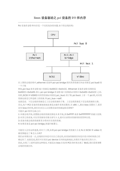
linux设备驱动之pci设备的I/O和内存------------------------------------------Pci设备的I/O和内存是一个比较复杂的问题.如下的总线结构:在上图的总线结构中,ethernet设备和pci-pci bridge的同类型资源空间必须要是pci bus0的一个子集例如,pci bus 0的I/O端口资源是0x00CC~0x01CC. Ethernet设备的I/O范围的是0x00CC~0x0xE0.那么pci-pci bridge的I/O端口范围就必须要在0x0xE0~0x01CC之间. 同样,SCSI和VIDEO同类型资源必须要是pci_bus1的子集.pci bus1上有一个pci桥,对应的资源也就是它所连桥上的资源.即pci_bus->self.也就是说,下层总线的资源是它上层总线资源的子集。
上层总线资源是下层总线资源的父集。
其实,每个PCI设备的资源地始地址都是由操作系统设置的.在x86上,都由bios设置好了.假若没有bios的时候,我们应该怎么去设置设备的资源起始范围呢?可能在pci枚举完成之后:1:从根总线开始,设置根总线的资源范围是从0开始,到0xFFFF或者0xFFFFFFFF的最大范围. 2:对其它的设备,可往其资源寄存器全部写入1,就可以求得该资源项的类型和长度.3:设备从根总线的资源那里分得对应长度的资源.4:如果设备是pci-pci bridge,则递归配置它.可能有人会有这样迷惑,对应于上图,如果pci-pci bridge的资源大小是N.而SCSI和video资源范围超过了N怎么办呢?我们必须要注意一点,总线的区间是可以自已设定的,而设备资源的区间是在设计的时候就已经确定好了.也就是说,我们可以更改pci device区间的起始地址,但我们不能改变它的大小.因此,出现了上面所说的这种情况.可能是由bios在处理PCI的时候出现了BUG.我们需要调整总线的资源区间.其实对于pci_bus的资源范围就是它的过滤窗口.对于过滤窗口的作用,我们在枚举的时候分析的很清楚了.CPU访问PC过程是这样的(只有一个根总线和pci-pci bridge过滤窗口功能打开的情况): 1:cpu向pci发出一个I/O请求.首先经过根总线.它会判断是否在它的资源范围内.如果在它的范围,它就会丢向总线所在的每一个设备.包括pci bridge. 如果没有在根总线的资源范围,则不会处理这个请求.2:如果pci设备判断该地址属于它的资源范围,则处理后发出应答4:pci bridge接收到这个请求,它会判断I/O地址是否在它的资源范围内.如果在它的范围,它会把它丢到它的下层子线.5:下层总线经过经过相同的处理后,就会找到这个PCI设备了一个PCI设备访问其它PCI设备或者其它外设的过程:1:首先这个PCI发出一个请求,这个请求会在总线上广播2:如果要请求的设备是在同级总线,就会产生应答3:请求的设备不是在同层总线,就会进行pci bridge.pci桥判断该请求不在它的范围内(目的地不是它下层的设备),就会将它丢向上层.4:这样辗转之后,就能找到对应的设备了经过这样的分析过来,相信对pci bridge的过滤窗口有更深的理解了.Linux中使用struct resource的结构来表示I/O端口或者是设备内存。
Linux系统下PCI转串口卡驱动安装方法
Linux系统下PCI转串口卡驱动安装方法由于公司产品要做行业市场,而产品与行业用户间PC的通讯为RS232串口方式。
而行业用户那里的PC都没有串行口,而且行业用户PC操作系统为Turbo Linux。
怎么办?办公室内有台机器是RedHat Linux 9.0 一个是Fedora Core 5 。
就先在这两个系统上试验吧。
这两台电脑上各自本身就有2个RS232串口。
一、PCI转串口卡安装型号NetMos Nm9835CV1、插入PCI卡到主机2、启动Linux,打开终端3、输入命令:#setserial /dev/ttyS0 -a (COM-1)显示内容:/dev/ttyS0, Line 0, UART: 16550A, Port: 0x3f8, irq: 4Baud_base: 115200, clos_delay: 50, divisor: 0closing_wait: 3000, closing_wait2: infiniteFlags: spd_normal skip_test4、输入命令:#setserial /dev/ttyS2 -a (COM-3)显示内容:/dev/ttyS2, Line 2, UART: unknown, Port: 0x3e8, irq: 4Baud_base: 115200, clos_delay: 50, divisor: 0closing_wait: 3000, closing_wait2: infiniteFlags: spd_normal skip_test第3、4步操作的目的主要是对主机自带串口及PCI扩展串口的区别。
区别在于4显示的内容中UART:未unknow。
不过若您检测这一步的时候UART为16550A而不是unknow,证明你的系统已经认识了扩展的串口,不需要进一步设置,直接跳入第8步测试就可以了。
5、需要输入命令查看一下您当前PCI检测的状态,以便对扩展串口进行设置#more /proc/pci会显示出一堆的信息,不要因为看不懂而吓坏了。
linuxpci枚举流程

linuxpci枚举流程1.PCI配置空间每个PCI设备都有一个256字节的配置空间,其中包含设备的标识符、寄存器等信息。
Linux内核通过读取这些PCI配置空间来识别和配置设备。
2.驱动加载当Linux内核启动时,它会自动加载与PCI设备相关的驱动程序模块。
驱动程序模块是内核扩展的一部分,用于控制和管理特定类型的PCI设备。
3.PCI总线扫描当驱动程序模块加载成功后,Linux内核将开始扫描主机上的PCI总线。
PCI总线是一个硬件接口,用于将CPU与PCI设备连接起来。
4.根总线控制器PCI总线上至少有一个根总线控制器,用于控制所有PCI设备的访问和数据传输。
Linux内核通过根总线控制器扫描整个PCI总线。
5.PCI总线配置空间扫描内核通过读取PCI总线上每个设备的配置空间来识别和配置设备。
它使用PCI配置空间中的设备ID、物理地址、中断号等信息来确定设备的类型和特性。
6.分配资源一旦设备被识别,内核将为其分配资源,例如物理内存、中断请求等。
分配资源是确保每个设备可以正确运行的重要步骤。
7.驱动绑定一旦设备被识别和配置,内核将为其加载正确的驱动程序。
驱动程序将与设备绑定,以便允许操作系统与设备进行交互。
8.驱动初始化加载驱动程序后,该驱动程序将进行初始化。
初始化过程可能包括设备注册、中断处理程序的安装和设备功能的启用等。
9.设备操作一旦设备被成功初始化,操作系统将能够通过驱动程序与设备进行交互。
这包括读取和写入设备寄存器、发送和接收数据等。
10.设备卸载当不再需要一些PCI设备时,可以卸载其驱动程序。
这将释放设备占用的资源,并将设备设置为未配置状态。
总的来说,Linux PCI枚举流程包括PCI配置空间、驱动加载、PCI总线扫描、根总线控制器、配置空间扫描、资源分配、驱动绑定、驱动初始化、设备操作和设备卸载等步骤。
这个流程确保了PCI设备被正确识别、配置和管理,并能够与操作系统进行正常的数据交互。
Linux下无线网卡驱动的安装

计算机系列教学文档------Linux下无线网卡驱动的安装Linux下无线网卡驱动的安装本来是我的本本比较旧,为了做一些网络实验,需要安装linux 操作系统,但系统安装完成后,无线网卡的驱动一直有问题,所以在网络上查找到这篇文章,希望对大家有用。
在ubuntu、BT5等linux 操作系统上通用。
The Ipw2200 is the Linux driver for the Intel PRO/Wireless 2200BG Mini-PCI Adapter and Intel PRO/Wireless 2915ABG Mini-PCI Adapter found in Centrino laptops. This driver only works on 2.6.x kernels (2.6.4 or newer).Starting with kernels 2.6.14 the driver is included in kernel.NOTE!Make sure you have installed the firmware! The ipw2200 documentation will tell you where to find these firmware files and where to install those.Included in mainline Linux kernels, tracking the SourceForge version with about 6 months delay.PackagesFedora Packages(1): Fedora Core includes the ipw2200-drivers in FC3 (with updates) and FC4. You still need to grab the firmware from /Fedora Packages(2): /name/ipw2200/Mandriva: The ipw2200 driver modules are included in the stock kernel package; the firmware is included in the commercial distribution or available from /.Gentoo: The driver is in the portage tree: emerge net-wireless/ipw2200 and net-wireless/ipw2200-firmwareDebian Sarge includes the source code for the modules in package ipw2200-source (/ipw2200-source). You additionally need to download firmware manually.Debian Etch includes a version of the modules in its kernel or for a later version install package ipw2200-modules-2.6-486 or ipw2200-modules-2.6-686 or ipw2200-modules-2.6-686-bigmem or ipw2200-modules-2.6-k7 or ipw2200-modules-2.6-amd64; or the source code for them in ipw2200-source (/ipw2200-source) to compile one yourself. You additionally need to download firmware manually.StatusIn development, usable, WEP 128bit encryption works, WPA and WPA2 work with drivers >= 1.0.2 using wpa_supplicant, monitor/rfmon is supported as with version >= 1.0.6. Generally works well, but some users experience problems (especially with firmware restarts and with WPA functionality using wpa_supplicant). Passing the hwcrypto=0 module parameter improves reliability for many users.The ipw2200 driver up to version 1.0.6 (in combination with some newer kernels) had a problem getting DHCP leases (it turned out to be a bug in the broadcasting code). Version 1.0.7 seems to have fixed this.Older ipw2200 driver versions shipped by many distributions have been reported to freeze a T43 after several minutes of intensive communication. Installing version 1.1.2 of the driver solved the problem.Latest stable versions:ipw2200 driver: 1.2.0firmware: 3.0ieee80211 stack: 1.2.15Latest development versions:ipw2200 driver: 1.2.2firmware: 3.1ieee80211 stack: 1.2.18Mainline kernels contain older (but mostly functional) versions of ipw2200 and ieee80211, and still require the addition of the firmware files. To get the latest versions you need to separately install the ipw2200 module and ieee80211 stack.InstallationSource CodeDownload the latest ieee80211 stack and install it:# tar xzvf ieee80211-1.2.15.tgz# cd ieee80211-1.2.15# make# make installDownload the latest ipw2200 module and install it:# tar xzvf ipw2200-1.2.0.tgz# cd ipw2200-1.2.0# make# make installDownload the matching firmware and install it:# tar xzvf ipw2200-fw-3.1.tgz -C /lib/firmwareDebian Sarge# apt-get install ipw2200-source# module-assistant -t build ipw2200-source[is this how module-assistant works in Sarge?]Debian EtchThe kernel includes a version but if you want a more recent version install the module ipw2200-modules-2.6-486 or ipw2200-modules-2.6-686 or ipw2200-modules-2.6-686-bigmem or ipw2200-modules-2.6-k7 or ipw2200-modules-2.6-amd64 depending on your architecture.The firmware is not distributed with Debian due to licensing reasons, download the matching version 3.0 firmware and install it:# tar -xvf ipw2200-fw-3.1.tgz -C /lib/firmware# mv /lib/firmware/ipw2200-fw-3.1/* /lib/firmwareDebian UnstableInstall ieee80211-source:# apt-get install ieee80211-source# module-assistant -t build ieee80211-sourceThe kernel includes a version but if you want a more recent version install the module ipw2200-modules-2.6-486 or ipw2200-modules-2.6-686 or ipw2200-modules-2.6-686-bigmem or ipw2200-modules-2.6-k7 or ipw2200-modules-2.6-amd64 depending on your architecture.There is a bug in the Debian package (last checked: Dec 30th 2005) that prevents from linking to ieee80211 modules using module-assistant. In case it is not fixed in your version, fall back to the regular source installation procedure described above.The firmware is not distributed with Debian due to licensing reasons, download the matching firmware and install it:# tar xzvf ipw2200-fw-2.4.tgz -C /usr/lib/hotplug/firmwaresee /etc/hotplug/firmware.agent for details on configured firmware locationsMake sure that your firmware files are not in a subdirectory (dmesg will give you warnings after any modprobe when firmware can’t be loaded)Fedora CoreInstallation on Fedora Core 5 works out of the box provided you install the ipw2200-firmware package. However, certain parts of the install process may not set up the wireless networking in a friendly manner using GNOME system tray icons and other tools. Bill Moss has written some excellent HowTo articles, including using VPNC to connect to a remote Cisco IPSec network.Fedora Core 5 and the IPW2200 Wireless DriverFedora Core 5 NetworkManager, NetworkManager-vpnc and Wireless Driver IPW2200Testing the driver# modprobe ipw2200# iwconfig# dmesg output might look similar to this:ieee80211: 802.11 data/management/control stack, 1.1.6ieee80211: Copyright (C) 2004-2005 Intel Corporation <jketreno@>ipw2200: Intel(R) PRO/Wireless 2200/2915 Network Driver, 1.0.8ipw2200: Copyright(c) 2003-2005 Intel Corporationipw2200: Detected Intel PRO/Wireless 2915ABG Network ConnectionNB: To make the wifi LED work on the thinkpad, pass the option led=1 to the kernel while loading the module. eg. # modprobe ipw2200 led=1. This can also be accomplished by adding that option to the file where your distribution looks for modprobe options so that it becomes automatic.In debian this can be done by putting a file named after the module in /etc/modutils with the options in ithere we might run a cmd like this# echo options ipw2200 led=1 > /etc/modutils/ipw2200then we must run update-modules to remake /etc/module.conf# update-modulesWPA supportUse wpa_supplicant with the -Dwext argument (not -Dipw), and pass the hwcrypto=0 argument to the ipw2200 module.There are some very detailed instructions with working sample configurations on the following link:ipw2200 WPA instructionPower ManagementThe ipw2200 driver has power management capabilities, which comes in handy while operating on battery.To enable reduced power consumption mode, issue:# iwpriv wlan0 set_power 7where wlan0 is the name of your interface. This will reduce idle power consumption by 1-2 Watts compared to no power management. To return to the “normal” operation mode, you can issue:# iwpriv wlan0 set_power 6.In order to check current settings, you can issue:# iwpriv wlan0 get_power.More information on these option is available in the README.ipw3945 file in the ipw3945 package (README.ipw2200 seems to be rather sketchy about the details of power management). You may want to turn power management on/off on demand in an ACPI script that catches battery/AC events, so that this happens automatically.Note that there have been reports that some versions of ipw2200 react with a firmware error to power management commands. This patch could alleviate the problem.To disable the radio (and further reduce power consumption) when the card is not in use, issue:# echo 1 > /sys/bus/pci/drivers/ipw2200/*/rf_killTo enable the radio, issue:# echo 0 > /sys/bus/pci/drivers/ipw2200/*/rf_killTo make the radio off by default after boot, addoptions ipw2200 disable=1to your /etc/modprobe.conf or equivalent (on kubuntu 6.10 /etc/modprobe.d/options).See README.ipw2200 in the ipw2200 package for details and other options.wpa_supplicant assigns a random SSID wasting powerMany wpa_supplicant versions implement disconnection by configuring a random SSID. ipw2200 reacts in a very unfortunate way to this, intensively scanning for this random SSID and wasting power. This waste can be seen in powertop.Here are a number of ways to solve this problem:Run iwconfig eth1 essid off after every wpa_supplicant disconnection.Upgrade to wpa_supplicant version 0.7.1 or higher. Starting from git commit 3145e615 wpa_supplicant does not configure ipw2200 with a random SSID any more.Backporting commit 3145e615 to wpa_supplicant version 0.6.8 also fixes the problem.Changing the enabled channelsPermitted WiFi channels vary with geography due to regulation. The EEPROM in this chip contains a country code (programmed by the hardware manufacturer), and the driver converts this to a channel list and enforces it.If you carry your laptop to a different regulatory region, you may need to change the list of permitted channels according to local regulations. There are two ways to accomplish this: Patching the ipw2200 driverYou can alter the ipw2200 driver sourcecode to hard-code the country code instead of reading it from EEPROM. For example, this will allow all 14 channels (perfect for those special occasions in international water):—ipw2200.c.orig+++ ipw2200.c@@ -11344,7 +11344,7 @@ static int ipw_up(struct ipw_priv *priv) memcpy(priv->net_dev->dev_addr, priv->mac_addr, ETH_ALEN); for (j = 0; j < ARRAY_SIZE(ipw_geos); j++) {- if (!memcmp(&priv->eeprom[EEPROM_COUNTRY_CODE],+ if (!memcmp(“ZZR”, ipw_geos[j].name, 3)) break; }For the list of codes and their meaning, see the “ipw_geos” table in the ipw2200.c sourcecode.Patching the EEPROMAlternatively, you can change the country code in the EEPROM once and for all, and then use the standard ipw2200 driver.See this guide:Patching the EEPROM.Instead of the hd program mentioned there, you can use the more common od program:echo -n ZZD | od -t x10000000 5a 5a 440000003ATTENTION!If this procedure goes wrong, you may ruin your wireless card.Additional CommentsYour kernel may include an old version of the ipw2200 driver. It is recommended to use the latest version.Make sure you also install the firmware version needed by the driver version you use. You can find the firmware here. To install it, decompress the .tgz file into /usr/lib/hotplug/firmware or /lib/firmware depending on your disto.The driver doesn’t appea r to support the MII interface, so any tools like automatic network configuration managers (i.e. whereami) that rely on mii-tool do not work.。
linux 模拟硬件拔插的命令

linux 模拟硬件拔插的命令在Linux系统中,模拟硬件拔插主要是通过对设备文件进行操作来实现的。
设备文件位于/dev目录下,可以通过特定的命令与其进行交互,相当于对设备进行操作。
以下是一些常见的模拟硬件拔插的命令。
1. modprobe命令:modprobe是Linux内核加载模块的命令,可以通过插拔驱动来加载/卸载模块。
使用modprobe命令可以模拟硬件的拔插操作。
a.加载模块:`sudo modprobe模块名`,例如:`sudo modprobe usb-storage`加载USB存储设备驱动模块。
b.卸载模块:`sudo modprobe -r模块名`,例如:`sudo modprobe -r usb-storage`卸载USB存储设备驱动模块。
2. lsusb命令:lsusb命令用于列出与USB相关的设备信息,可以用来查看已插入的USB设备。
a.列出已连接的USB设备:`lsusb`,该命令会列出已连接的USB 设备的详细信息,包括设备ID、制造商等。
b.列出指定制造商的USB设备:`lsusb -d制造商ID`,例如:`lsusb -d 0424:`列出VID(Vendor ID)为0424的USB设备。
3. lshw命令:lshw命令用于显示硬件信息,可以通过该命令查看系统中的设备信息。
a.列出所有设备信息:`sudo lshw`,该命令会显示系统中所有的硬件信息,包括CPU、内存、磁盘等。
b.列出指定设备信息:`sudo lshw -class设备类别`,例如:`sudo lshw -class disk`列出磁盘设备的详细信息。
4. udevadm命令:udevadm命令用于管理Linux的udev设备管理器,可以监控设备的动态插拔。
a.监控所有设备的插拔事件:`sudo udevadm monitor`,该命令会实时显示设备的插拔信息。
b.监控指定设备的插拔事件:`sudo udevadm monitor --udev`,例如:`sudo udevadm monitor --udev -s subsystem=block -p`监控磁盘设备的插拔事件。
Linux系统配置双显卡教程

Linux系统配置双显卡教程通常Linux系统只能一直使用核心显卡或独立显卡,这样对操作是非常不友好的。
那么能不能配置双显卡功能呢?今天小编要给大家介绍“Bumblebee”,它可以完美解决Linux系统这个缺陷。
下面我们来看看Linux系统如何配置双显卡吧!Linux系统配置双显卡的操作教程:一、配置bumblebee小编所有指令对应于Arch Linux 64位版。
首先,安装英伟达官方的显卡驱动程序:sudo pacman -S nvidia选择和你目前的操作系统相匹配的驱动程序,比如小编的是Linux 4.9内核,应该选带有linux49字样的包。
等待安装完成,期间你应该会看到类似的输出:然后安装bumblebee软件包:sudo pacman -S bumblebee安装完成之后,记得检查当前用户是否在用户组“bumblebee”内。
如果不是,请手动添加。
重启计算机,以使英伟达驱动被正确加载,并使bumblebee守护进程启动。
二、测试bumblebeeBumblebee提供了指令optirun,以使用户在会话仍然以集成显卡渲染的情况下,使用独立显卡渲染指定的应用。
我们使用加了光影和视差贴图材质包的MC(Minecraft,我的世界)来检查独立显卡的运行状态。
首先我们采用常规的方式启动MC,小编用的是HMCL启动器:下面是比较吃配置的资源包和光影:从第二张截图还能看出,MC识别出了我们的显卡型号:Intel HD Graphics 5500,也就是小编的集成显卡。
我们新建一个世界,进去看看:这根本就不能正确渲染。
下面我们使用optirun指令来执行MC:进入到光影选项,发现MC已经正确识别了我们的显卡:我们进入一个世界:嗯,光影正常工作了,帧率也很高,这意味着这个程序一定是高性能独立显卡在渲染了。
如果你能正常使用optirun指令,那么你的配置就完成了。
补充:系统常用维护技巧1,在“开始” 菜单中选择“控制面板” 选项,打开“控制面板” 窗口,单击“管理工具” 链接2,在打开的“管理工具” 窗口中双击“事件查看器” 图标3,接着会打开“事件查看器” 窗口4,在右侧窗格中的树状目录中选择需要查看的日志类型,如“事件查看器本地--Win日志--系统日志,在接着在中间的“系统” 列表中即查看到关于系统的事件日志5,双击日志名称,可以打开“事件属性” 对话框,切换到“常规” 选项卡,可以查看该日志的常规描述信息6,切换到“详细信息” 选项卡,可以查看该日志的详细信息7,打开“控制面板” 窗口,单击“操作中心” 链接,打开“操作中心” 窗口,展开“维护” 区域8,单击“查看可靠性历史记录” 链接,打开“可靠性监视程序” 主界面,如图所示,用户可以选择按天或者按周为时间单位来查看系统的稳定性曲线表,如果系统近日没出过什么状况,那么按周来查看会比较合适。
linux查看显卡

linux查看显卡
Linux系统下,可以使用一些命令和工具来查看显卡信息。
1. lspci命令:用于列举PCI设备的信息,包括显卡。
```shell
lspci | grep -i vga
```
这个命令会列出计算机上安装的显卡信息,包括制造商、型号和供应商信息。
2. lshw命令:用于显示硬件的信息,包括显卡。
```shell
sudo lshw -C display
```
这个命令会显示所有可用的显示设备的详细信息,包括制造商、型号、驱动程序等。
3. nvidia-smi命令:适用于NVIDIA显卡,用于查看显卡的相
关信息。
```shell
nvidia-smi
```
这个命令会显示NVIDIA显卡的状态、驱动程序版本、显存
使用情况等信息。
4. glxinfo命令:用于查看OpenGL相关的信息。
```shell
glxinfo | grep "OpenGL version"
```
这个命令会显示OpenGL版本信息,可以用来确认显卡是否支持OpenGL。
5. inxi命令:适用于Debian和Ubuntu系统,用于查看系统信息,包括显卡。
```shell
inxi -G
```
这个命令会显示显卡的详细信息,包括制造商、型号和驱动程序等。
以上是一些常用的命令和工具来查看Linux系统下的显卡信息。
不同的Linux发行版可能会有所不同,可以根据实际情况选择
合适的命令来查看显卡信息。
- 1、下载文档前请自行甄别文档内容的完整性,平台不提供额外的编辑、内容补充、找答案等附加服务。
- 2、"仅部分预览"的文档,不可在线预览部分如存在完整性等问题,可反馈申请退款(可完整预览的文档不适用该条件!)。
- 3、如文档侵犯您的权益,请联系客服反馈,我们会尽快为您处理(人工客服工作时间:9:00-18:30)。
§3 PCI 配置空间PCI 规范定义了三种类型的PCI 配置空间头部。
其中type 0用于标准的PCI 设备,type 1用于PCI 桥,type 2用于PCI CardBus 桥。
关于这三种类型的配置空间头部的具体信息可以参见PCI 规范文档。
不管是哪一种类型的配置空间头部,其前16个字节的格式都是相同的。
如下图6所示:因此,Linux 在include/linux/pci.h 头文件中一开始就定义了这相同格式的前16个字节。
如下:(1)厂商ID 和设备ID 寄存器的定义如下:#define PCI_VENDOR_ID 0x00 /* 16 bits */#define PCI_DEVICE_ID 0x02 /* 16 bits */(2)命令寄存器的定义如下:#define PCI_COMMAND 0x04 /* 16 bits */#define PCI_COMMAND_IO 0x1 /* Enable response in I/O space */#define PCI_COMMAND_MEMORY 0x2 /* Enable response in Memory space */ #define PCI_COMMAND_MASTER0x4 /* Enable bus mastering */#define PCI_COMMAND_SPECIAL0x8 /* Enable response to special cycles */#define PCI_COMMAND_INVALIDATE 0x10 /* Use memory write and invalidate */ #define PCI_COMMAND_VGA_PALETTE 0x20 /* Enable palette snooping */#define PCI_COMMAND_PARITY 0x40 /* Enable parity checking */#define PCI_COMMAND_WAIT 0x80 /* Enable address/data stepping */#define PCI_COMMAND_SERR 0x100 /* Enable SERR */#define PCI_COMMAND_FAST_BACK 0x200 /* Enable back-to-back writes */在上述宏定义中,宏PCI_COMMAND 表示命令寄存器在PCI 配置空间头部的位置,而其余10个PCI_COMMAND_XXX 宏定义则表示命令寄存器中各位的掩码。
PCI 规范当前只使用了命令寄存器中的低10位,具体含义可以参阅PCI 总线规范。
(3)状态寄存器的定义如下:#define PCI_STATUS 0x06 /* 16 bits */#define PCI_STATUS_CAP_LIST 0x10 /* Support Capability List */00h 04h 08h 0ch 3ch图6 PCI 配置空间头部的前16个字节#define PCI_STATUS_66MHZ 0x20 /* Support 66 Mhz PCI 2.1 bus */#define PCI_STATUS_UDF 0x40 /* Support User Definable Features [obsolete] */#define PCI_STATUS_FAST_BACK 0x80 /* Accept fast-back to back */#define PCI_STATUS_PARITY 0x100 /* Detected parity error */#define PCI_STATUS_DEVSEL_MASK 0x600 /* DEVSEL timing */#define PCI_STATUS_DEVSEL_FAST 0x000#define PCI_STATUS_DEVSEL_MEDIUM 0x200#define PCI_STATUS_DEVSEL_SLOW 0x400#define PCI_STATUS_SIG_TARGET_ABORT 0x800 /* Set on target abort */#define PCI_STATUS_REC_TARGET_ABORT 0x1000 /* Master ack of " */#define PCI_STATUS_REC_MASTER_ABORT 0x2000 /* Set on master abort */#define PCI_STATUS_SIG_SYSTEM_ERROR 0x4000 /* Set when we drive SERR */#define PCI_STATUS_DETECTED_PARITY 0x8000 /* Set on parity error */在上述宏定义中,宏PCI_STATUS表示状态寄存器在配置空间头部的位置。
而其余PCI_STATUS_XXX宏则表示状态寄存器中各位的含义。
注意!PCI规范当前只使用状态寄存器中的高12位,而低4位被保留。
(4)类代码和修订版本寄存器的定义如下:#define PCI_CLASS_REVISION 0x08 /* High 24 bits are class, low 8 revision */#define PCI_REVISION_ID 0x08 /* Revision ID */#define PCI_CLASS_PROG 0x09 /* Reg. Level Programming Interface */#define PCI_CLASS_DEVICE 0x0a /* Device class */其中,宏PCI_CLASS_REVISION用来指示类代码寄存器和修订版本寄存器一起所占用的双字在PCI配置空间中的位置,因此如果要一次性地读写这个双字的内容,就可以用该宏来作为配置空间中的地址索引。
而宏PCI_REVISION_ID则作为配置空间中RevisionID这个字节的配置空间地址索引,而宏PCI_CLASS_PROG则是配置空间中ClassCode中的配置接口字节的地址索引,宏PCI_CLASS_DEVICE表示类与子类这个word在配置空间中的字地址索引。
关于类代码和修订版本寄存器的具体格式请参阅PCI 规范文档。
(5)宏PCI_CACHE_LINE_SIZE表示配置空间头部中的Cache Line Size寄存器在配置空间中的字节地址索引。
(6)宏PCI_LATENCY_TIMER表示配置空间头部中的Latency Timer寄存器在配置空间中的字节地址索引。
(7)宏PCI_HEADER_TYPE表示配置空间头部中的HeaderType寄存器在配置空间中的字节地址索引。
HeaderType字节中的低7位表示配置空间头部的类型,值00h表示是标准PCI设备的配置空间头部,值01h表示PCI-to-PCI桥的配置空间头部,值02h表示CardBus桥的配置空间头部。
(8)宏PCI_BIST表示配置空间头部中的BIST寄存器(Built-In Self-Test)在配置空间中的字节地址索引。
BIST寄存器中的bit[3:0]表示完成代码,bit[7]表示设备是否支持BIST,bit[6]用来启动BIST。
通常设备自检因该在2秒内完成。
上述几个宏的完整定义如下:#define PCI_CACHE_LINE_SIZE 0x0c /* 8 bits */#define PCI_LATENCY_TIMER 0x0d /* 8 bits */#define PCI_HEADER_TYPE 0x0e /* 8 bits */#define PCI_HEADER_TYPE_NORMAL0#define PCI_HEADER_TYPE_BRIDGE 1#define PCI_HEADER_TYPE_CARDBUS 2#define PCI_BIST 0x0f /* 8 bits */#define PCI_BIST_CODE_MASK 0x0f /* Return result */#define PCI_BIST_START 0x40 /* 1 to start BIST, 2 secs or less */#define PCI_BIST_CAPABLE 0x80 /* 1 if BIST capable */§3.1 基地址寄存器(BAR)宏PCI_BASE_ADDRESS_0到PCI_BASE_ADDRESS_5分别表示配置空间头部中的基地址寄存器0~基地址寄存器5在配置空间中的双字地址索引。
其中,PCI_BASE_ADDRESS_2~5仅对标准PCI设备的0类型配置空间头部才有意义,而PCI_BASE_ADDRESS_0~1则适用于0类型和1类型配置空间头部。
BAR 中的bit[0]的值决定了这个BAR所指定的地址范围是在I/O映射空间内进行译码,还是在Memory映射空间内进行译码。
因此,宏PCI_BASE_ADDRESS_SPACE表示BAR中bit[0]位的位掩码,而宏PCI_BASE_ADDRESS_SPACE_IO和PCI_BASE_ADDRESS_SPACE_MEMORY就分别表示bit[0]位的两种可能值,也就分别对应于I/O映射空间和内存映射空间。
当BAR所指定的地址范围位于内存映射空间中时,BAR中的bit[2:1]这两位表示内存地址的类型。
因此宏PCI_BASE_ADDRESS_MEM_TYPE_MASK就表示bit[2:1]这两位的位掩码值。
而PCI_BASE_ADDRESS_MEM_TYPE_32/1M/64这三个宏则表示三种可能的内存地址类型。
BAR中的bit[3]表示内存范围是否为可预取(Prefetchable)的内存,宏PCI_BASE_ADDRESS_MEM_PREFETCH对应于这一位。
最后,宏PCI_BASE_ADDRESS_MEM_MASK(~0x0fUL=0xfffffff0)表示内存映射方式下的BAR 中有效内存地址位掩码,显然PCI总线中最小的内存范围是256字节。
宏PCI_BASE_ADDRESS_IO_MASK (~0x03UL=0xfffffff8)表示I/O映射方式下的BAR中有效的I/O地址位掩码。
显然PCI总线中最小的I/O 地址范围是8个字节。
所有上述这些宏的定义如下:/** Base addresses specify locations in memory or I/O space.* Decoded size can be determined by writing a value of* 0xffffffff to the register, and reading it back. Only* 1 bits are decoded.*/#define PCI_BASE_ADDRESS_00x10 /* 32 bits */#define PCI_BASE_ADDRESS_10x14 /* 32 bits [htype 0,1 only] */#define PCI_BASE_ADDRESS_20x18 /* 32 bits [htype 0 only] */#define PCI_BASE_ADDRESS_30x1c /* 32 bits */#define PCI_BASE_ADDRESS_40x20 /* 32 bits */#define PCI_BASE_ADDRESS_50x24 /* 32 bits */#define PCI_BASE_ADDRESS_SPACE 0x01 /* 0 = memory, 1 = I/O */#define PCI_BASE_ADDRESS_SPACE_IO 0x01#define PCI_BASE_ADDRESS_SPACE_MEMORY 0x00#define PCI_BASE_ADDRESS_MEM_TYPE_MASK 0x06#define PCI_BASE_ADDRESS_MEM_TYPE_32 0x00 /* 32 bit address */#define PCI_BASE_ADDRESS_MEM_TYPE_1M 0x02 /* Below 1M [obsolete] */#define PCI_BASE_ADDRESS_MEM_TYPE_64 0x04 /* 64 bit address */#define PCI_BASE_ADDRESS_MEM_PREFETCH 0x08 /* prefetchable? */#define PCI_BASE_ADDRESS_MEM_MASK(~0x0fUL)#define PCI_BASE_ADDRESS_IO_MASK (~0x03UL)/* bit 1 is reserved if address_space = 1 */§3.2 类型0配置空间头部标准PCI设备的0类型配置空间头部的其余寄存器定义如下:/* Header type 0 (normal devices) */#define PCI_CARDBUS_CIS 0x28#define PCI_SUBSYSTEM_VENDOR_ID 0x2c#define PCI_SUBSYSTEM_ID 0x2e#define PCI_ROM_ADDRESS 0x30 /* Bits 31..11 are address, 10..1 reserved */#define PCI_ROM_ADDRESS_ENABLE 0x01#define PCI_ROM_ADDRESS_MASK (~0x7ffUL)#define PCI_CAPABILITY_LIST 0x34 /* Offset of first capability list entry *//* 0x35-0x3b are reserved */#define PCI_INTERRUPT_LINE 0x3c /* 8 bits */#define PCI_INTERRUPT_PIN 0x3d /* 8 bits */#define PCI_MIN_GNT 0x3e /* 8 bits */#define PCI_MAX_LAT 0x3f /* 8 bits */这里对ROM地址寄存器的定义说明一下。
