AAT8641中文资料
6EGG8-2;1EHG1-2;1EGS1-1;1EGS1-2;3EGG8-2;中文规格书,Datasheet资料

Available Part Numbers
Filtered modules 1EGG1-1 3EGG1-1 6EGG1-1 10EGG1-1 1EGG1-2 3EGG1-2 6EGG1-2 10EGG1-2 1EGG8-1 3EGG8-1 6EGG8-1 10EGG8-1 1EGG8-2 3EGG8-2 6EGG8-2 10EGG8-2 1EGS1-1 3EGS1-1 6EGS1-1 10EGS1-1 1EGS1-2 3EGS1-2 6EGS1-2 10EGS1-2 Filtered modules with ground circuit inductor 1EGG1C-1 3EGG1C-1 6EGG1C-1 1EGG1C-2 3EGG1C-2 6EGG1C-2 1EGG8C-1 3EGG8C-1 6EGG8C-1 1EGG8C-2 3EGG8C-2 6EGG8C-2 Medical filter modules 1EHG1-2 3EHG1-2 6EHG1-2 10EHG1-2 1EHG8-2 3EHG8-2 6EHG8-2 10EHG8-2 1EHGS1-2 3EHGS1-2 6EHGS1-2 10EHGS1-2
For email, phone or live chat, please go to /help
/
Corcom Product Guide
Catalog: 1654001 Issue Date: 06.2011
Smallest Power Entry Module with Metric Fuse Holders (continued)
(not included)
HG Series
• Medical version of our GG Series • Mechanically identical to GG Series • Available only with dual fusing
MAX13085EESA-T中文资料

General DescriptionThe MAX13080E–MAX13089E +5.0V, ±15kV ESD-protect-ed, RS-485/RS-422 transceivers feature one driver and one receiver. These devices include fail-safe circuitry,guaranteeing a logic-high receiver output when receiver inputs are open or shorted. The receiver outputs a logic-high if all transmitters on a terminated bus are disabled (high impedance). The MAX13080E–MAX13089E include a hot-swap capability to eliminate false transitions on the bus during power-up or hot insertion.The MAX13080E/MAX13081E/MAX13082E feature reduced slew-rate drivers that minimize EMI and reduce reflections caused by improperly terminated cables, allowing error-free data transmission up to 250kbps. The MAX13083E/MAX13084E/MAX13085E also feature slew-rate-limited drivers but allow transmit speeds up to 500kbps. The MAX13086E/MAX13087E/MAX13088E driver slew rates are not limited, making transmit speeds up to 16Mbps possible. The MAX13089E slew rate is pin selectable for 250kbps,500kbps, and 16Mbps.The MAX13082E/MAX13085E/MAX13088E are intended for half-duplex communications, and the MAX13080E/MAX13081E/MAX13083E/MAX13084E/MAX13086E/MAX13087E are intended for full-duplex communica-tions. The MAX13089E is selectable for half-duplex or full-duplex operation. It also features independently programmable receiver and transmitter output phase through separate pins.The MAX13080E–MAX13089E transceivers draw 1.2mA of supply current when unloaded or when fully loaded with the drivers disabled. All devices have a 1/8-unit load receiver input impedance, allowing up to 256transceivers on the bus.The MAX13080E/MAX13083E/MAX13086E/MAX13089E are available in 14-pin PDIP and 14-pin SO packages.The MAX13081E/MAX13082E/MAX13084E/MAX13085E/MAX13087E/MAX13088E are available in 8-pin PDIP and 8-pin SO packages. The devices operate over the com-mercial, extended, and automotive temperature ranges.ApplicationsUtility Meters Lighting Systems Industrial Control Telecom Security Systems Instrumentation ProfibusFeatures♦+5.0V Operation♦Extended ESD Protection for RS-485/RS-422 I/O Pins±15kV Human Body Model ♦True Fail-Safe Receiver While Maintaining EIA/TIA-485 Compatibility ♦Hot-Swap Input Structures on DE and RE ♦Enhanced Slew-Rate Limiting Facilitates Error-Free Data Transmission(MAX13080E–MAX13085E/MAX13089E)♦Low-Current Shutdown Mode (Except MAX13081E/MAX13084E/MAX13087E)♦Pin-Selectable Full-/Half-Duplex Operation (MAX13089E)♦Phase Controls to Correct for Twisted-Pair Reversal (MAX13089E)♦Allow Up to 256 Transceivers on the Bus ♦Available in Industry-Standard 8-Pin SO PackageMAX13080E–MAX13089E+5.0V , ±15kV ESD-Protected, Fail-Safe, Hot-Swap, RS-485/RS-422 Transceivers________________________________________________________________Maxim Integrated Products 1Ordering Information19-3590; Rev 1; 4/05For pricing, delivery, and ordering information,please contact Maxim/Dallas Direct!at 1-888-629-4642, or visit Maxim’s website at .Selector Guide, Pin Configurations, and Typical Operating Circuits appear at end of data sheet.Ordering Information continued at end of data sheet.M A X 13080E –M A X 13089E+5.0V , ±15kV ESD-Protected, Fail-Safe, Hot-Swap, RS-485/RS-422 Transceivers 2_______________________________________________________________________________________ABSOLUTE MAXIMUM RATINGSDC ELECTRICAL CHARACTERISTICS(V CC = +5.0V ±10%, T A = T MIN to T MAX , unless otherwise noted. Typical values are at V CC = +5.0V and T A = +25°C.) (Note 1)Stresses beyond those listed under “Absolute Maximum Ratings” may cause permanent damage to the device. These are stress ratings only, and functional operation of the device at these or any other conditions beyond those indicated in the operational sections of the specifications is not implied. Exposure to absolute maximum rating conditions for extended periods may affect device reliability.(All Voltages Referenced to GND)Supply Voltage (V CC ).............................................................+6V Control Input Voltage (RE , DE, SLR,H/F , TXP, RXP)......................................................-0.3V to +6V Driver Input Voltage (DI)...........................................-0.3V to +6V Driver Output Voltage (Z, Y, A, B).............................-8V to +13V Receiver Input Voltage (A, B)....................................-8V to +13V Receiver Input VoltageFull Duplex (A, B)..................................................-8V to +13V Receiver Output Voltage (RO)....................-0.3V to (V CC + 0.3V)Driver Output Current.....................................................±250mAContinuous Power Dissipation (T A = +70°C)8-Pin SO (derate 5.88mW/°C above +70°C).................471mW 8-Pin Plastic DIP (derate 9.09mW/°C above +70°C).....727mW 14-Pin SO (derate 8.33mW/°C above +70°C)...............667mW 14-Pin Plastic DIP (derate 10.0mW/°C above +70°C)...800mW Operating Temperature RangesMAX1308_EC_ _.................................................0°C to +75°C MAX1308_EE_ _..............................................-40°C to +85°C MAX1308_EA_ _............................................-40°C to +125°C Junction Temperature......................................................+150°C Storage Temperature Range.............................-65°C to +150°C Lead Temperature (soldering, 10s).................................+300°CMAX13080E–MAX13089E+5.0V , ±15kV ESD-Protected, Fail-Safe, Hot-Swap, RS-485/RS-422 Transceivers_______________________________________________________________________________________3DC ELECTRICAL CHARACTERISTICS (continued)(V CC = +5.0V ±10%, T A = T MIN to T MAX , unless otherwise noted. Typical values are at V CC = +5.0V and T A = +25°C.) (Note 1)M A X 13080E –M A X 13089E+5.0V , ±15kV ESD-Protected, Fail-Safe, Hot-Swap, RS-485/RS-422 Transceivers 4_______________________________________________________________________________________DRIVER SWITCHING CHARACTERISTICSMAX13080E/MAX13081E/MAX13082E/MAX13089E WITH SRL = UNCONNECTED (250kbps)(V CC = +5.0V ±10%, T A = T MIN to T MAX , unless otherwise noted. Typical values are at V CC = +5.0V and T A = +25°C.)RECEIVER SWITCHING CHARACTERISTICSMAX13080E/MAX13081E/MAX13082E/MAX13089E WITH SRL = UNCONNECTED (250kbps)(V CC = +5.0V ±10%, T A = T MIN to T MAX , unless otherwise noted. Typical values are at V CC = +5.0V and T A = +25°C.)MAX13080E–MAX13089E+5.0V , ±15kV ESD-Protected, Fail-Safe, Hot-Swap, RS-485/RS-422 Transceivers_______________________________________________________________________________________5DRIVER SWITCHING CHARACTERISTICSMAX13083E/MAX13084E/MAX13085E/MAX13089E WITH SRL = V CC (500kbps)(V CC = +5.0V ±10%, T A = T MIN to T MAX , unless otherwise noted. Typical values are at V CC = +5.0V and T A = +25°C.)RECEIVER SWITCHING CHARACTERISTICSMAX13083E/MAX13084E/MAX13085E/MAX13089E WITH SRL = V CC (500kbps)(V CC = +5.0V ±10%, T A = T MIN to T MAX , unless otherwise noted. Typical values are at V CC = +5.0V and T A = +25°C.)M A X 13080E –M A X 13089E+5.0V , ±15kV ESD-Protected, Fail-Safe, Hot-Swap, RS-485/RS-422 Transceivers 6_______________________________________________________________________________________DRIVER SWITCHING CHARACTERISTICSMAX13086E/MAX13087E/MAX13088E/MAX13089E WITH SRL = GND (16Mbps)(V CC = +5.0V ±10%, T A = T MIN to T MAX , unless otherwise noted. Typical values are at V CC = +5.0V and T A = +25°C.)RECEIVER SWITCHING CHARACTERISTICSMAX13086E/MAX13087E/MAX13088E/MAX13089E WITH SRL = GND (16Mbps)(V CC = +5.0V ±10%, T A = T MIN to T MAX , unless otherwise noted. Typical values are at V CC = +5.0V and T A = +25°C.)Note 2:∆V OD and ∆V OC are the changes in V OD and V OC , respectively, when the DI input changes state.Note 3:The short-circuit output current applies to peak current just prior to foldback current limiting. The short-circuit foldback outputcurrent applies during current limiting to allow a recovery from bus contention.MAX13080E–MAX13089E+5.0V , ±15kV ESD-Protected, Fail-Safe, Hot-Swap, RS-485/RS-422 Transceivers_______________________________________________________________________________________70.800.901.501.101.001.201.301.401.60-40-10520-253550958011065125SUPPLY CURRENT vs. TEMPERATURETEMPERATURE (°C)S U P P L Y C U R R E N T (m A )0201040305060021345OUTPUT CURRENTvs. RECEIVER OUTPUT-HIGH VOLTAGEM A X 13080E -89E t o c 02OUTPUT HIGH VOLTAGE (V)O U T P U T C U R R E N T (m A )20104030605070021345OUTPUT CURRENTvs. RECEIVER OUTPUT-LOW VOLTAGEM A X 13080E -89E t o c 03OUTPUT LOW VOLTAGE (V)O U T P U T C U R R E N T (m A )4.04.44.24.84.65.25.05.4RECEIVER OUTPUT-HIGH VOLTAGEvs. TEMPERATURETEMPERATURE (°C)O U T P U T H I G H V O L T A G E (V )-40-10520-2535509580110651250.10.70.30.20.40.50.60.8RECEIVER OUTPUT-LOW VOLTAGEvs. TEMPERATURETEMPERATURE (°C)O U T P U T L O W V O L T A G E (V )-40-10520-25355095801106512502040608010012014016012345DRIVER DIFFERENTIAL OUTPUT CURRENT vs. DIFFERENTIAL OUTPUT VOLTAGEDIFFERENTIAL OUTPUT VOLTAGE (V)D I F FE R E N T I A L O U T P U T C U R R E N T (m A )2.02.82.43.63.24.44.04.8DRIVER DIFFERENTIAL OUTPUT VOLTAGE vs. TEMPERATURED I F FE R E N T I A L O U T P U T V O L T A G E (V )-40-10520-253550958011065125TEMPERATURE (°C)40201008060120140180160200-7-5-4-6-3-2-1012354OUTPUT CURRENT vs. TRANSMITTEROUTPUT-HIGH VOLTAGEOUTPUT HIGH VOLTAGE (V)O U T P U T C U R R E N T (m A )60402080100120140160180200042681012OUTPUT CURRENT vs. TRANSMITTEROUTPUT-LOW VOLTAGEOUTPUT-LOW VOLTAGE (V)O U T P U T C U R R E N T (m A )Typical Operating Characteristics(V CC = +5.0V, T A = +25°C, unless otherwise noted.)M A X 13080E –M A X 13089E+5.0V , ±15kV ESD-Protected, Fail-Safe, Hot-Swap, RS-485/RS-422 Transceivers 8_______________________________________________________________________________________21543679810SHUTDOWN CURRENT vs. TEMPERATUREM A X 13080E -89E t o c 10S H U T D O W N C U R R E N T (µA )-40-10520-253550958011065125TEMPERATURE (°C)600800700100090011001200DRIVER PROPAGATION DELAY vs. TEMPERATURE (250kbps)D R I VE R P R O P A G A T I O N D E L A Y (n s )-40-10520-253550958011065125TEMPERATURE (°C)300400350500450550600DRIVER PROPAGATION DELAY vs. TEMPERATURE (500kbps)D R I VE R P R O P A G A T I O N D E L A Y (n s )-40-10520-253550958011065125TEMPERATURE (°C)1070302040506080DRIVER PROPAGATION DELAY vs. TEMPERATURE (16Mbps)D R I VE R P R O P A G A T I O N D E L A Y (n s )-40-10520-253550958011065125TEMPERATURE (°C)40201008060120140160180RECEIVER PROPAGATION DELAYvs. TEMPERATURE (250kpbs AND 500kbps)R E C E I V E R P R O P A G A T I O N D E L A Y (n s )-40-10520-253550958011065125TEMPERATURE (°C)40201008060120140160180RECEIVER PROPAGATION DELAYvs. TEMPERATURE (16Mbps)R EC E I V E R P R O P A G AT I O N D E L A Y (n s )-40-10520-253550958011065125TEMPERATURE (°C)2µs/div DRIVER PROPAGATION DELAY (250kbps)DI 2V/divV Y - V Z 5V/divR L = 100Ω200ns/divRECEIVER PROPAGATION DELAY(250kbps AND 500kbps)V A - V B 5V/divRO 2V/divTypical Operating Characteristics (continued)(V CC = +5.0V, T A = +25°C, unless otherwise noted.)MAX13080E–MAX13089E+5.0V , ±15kV ESD-Protected, Fail-Safe, Hot-Swap, RS-485/RS-422 Transceivers_______________________________________________________________________________________9Test Circuits and Waveforms400ns/divDRIVER PROPAGATION DELAY (500kbps)DI 2V/divR L = 100ΩV Y - V Z 5V/div10ns/div DRIVER PROPAGATION DELAY (16Mbps)DI 2V/divR L = 100ΩV Y 2V/divV Z 2V/div40ns/divRECEIVER PROPAGATION DELAY (16Mbps)V B 2V/divR L = 100ΩRO 2V/divV A 2V/divTypical Operating Characteristics (continued)(V CC = +5.0V, T A = +25°C, unless otherwise noted.)Figure 2. Driver Timing Test CircuitM A X 13080E –M A X 13089E+5.0V , ±15kV ESD-Protected, Fail-Safe, Hot-Swap, RS-485/RS-422 Transceivers 10______________________________________________________________________________________Test Circuits and Waveforms (continued)Figure 4. Driver Enable and Disable Times (t DHZ , t DZH , t DZH(SHDN))DZL DLZ DLZ(SHDN)MAX13080E–MAX13089E+5.0V , ±15kV ESD-Protected, Fail-Safe, Hot-Swap, RS-485/RS-422 TransceiversTest Circuits and Waveforms (continued)Figure 6. Receiver Propagation Delay Test CircuitM A X 13080E –M A X 13089E+5.0V , ±15kV ESD-Protected, Fail-Safe, Hot-Swap, RS-485/RS-422 TransceiversMAX13080E–MAX13089E+5.0V , ±15kV ESD-Protected, Fail-Safe, Hot-Swap, RS-485/RS-422 TransceiversMAX13080E/MAX13083E/MAX13086EMAX13081E/MAX13084E/MAX13086E/MAX13087EFunction TablesM A X 13080E –M A X 13089E+5.0V , ±15kV ESD-Protected, Fail-Safe, Hot-Swap, RS-485/RS-422 Transceivers MAX13082E/MAX13085E/MAX13088EFunction Tables (continued)MAX13089EDetailed Description The MAX13080E–MAX13089E high-speed transceivers for RS-485/RS-422 communication contain one driver and one receiver. These devices feature fail-safe circuit-ry, which guarantees a logic-high receiver output when the receiver inputs are open or shorted, or when they are connected to a terminated transmission line with all dri-vers disabled (see the Fail-Safe section). The MAX13080E/MAX13082E/MAX13083E/MAX13085E/ MAX13086E/MAX13088E/MAX13089E also feature a hot-swap capability allowing line insertion without erroneous data transfer (see the Hot Swap Capability section). The MAX13080E/MAX13081E/MAX13082E feature reduced slew-rate drivers that minimize EMI and reduce reflec-tions caused by improperly terminated cables, allowing error-free data transmission up to 250kbps. The MAX13083E/MAX13084E/MAX13085E also offer slew-rate limits allowing transmit speeds up to 500kbps. The MAX13086E/MAX13087E/MAX13088Es’ driver slew rates are not limited, making transmit speeds up to 16Mbps possible. The MAX13089E’s slew rate is selectable between 250kbps, 500kbps, and 16Mbps by driving a selector pin with a three-state driver.The MAX13082E/MAX13085E/MAX13088E are half-duplex transceivers, while the MAX13080E/MAX13081E/ MAX13083E/MAX13084E/MAX13086E/MAX13087E are full-duplex transceivers. The MAX13089E is selectable between half- and full-duplex communication by driving a selector pin (H/F) high or low, respectively.All devices operate from a single +5.0V supply. Drivers are output short-circuit current limited. Thermal-shutdown circuitry protects drivers against excessive power dissi-pation. When activated, the thermal-shutdown circuitry places the driver outputs into a high-impedance state.Receiver Input Filtering The receivers of the MAX13080E–MAX13085E, and the MAX13089E when operating in 250kbps or 500kbps mode, incorporate input filtering in addition to input hysteresis. This filtering enhances noise immunity with differential signals that have very slow rise and fall times. Receiver propagation delay increases by 25% due to this filtering.Fail-Safe The MAX13080E family guarantees a logic-high receiver output when the receiver inputs are shorted or open, or when they are connected to a terminated transmission line with all drivers disabled. This is done by setting the receiver input threshold between -50mV and -200mV. If the differential receiver input voltage (A - B) is greater than or equal to -50mV, RO is logic-high. If (A - B) is less than or equal to -200mV, RO is logic-low. In the case of a terminated bus with all transmitters disabled, the receiv-er’s differential input voltage is pulled to 0V by the termi-nation. With the receiver thresholds of the MAX13080E family, this results in a logic-high with a 50mV minimumnoise margin. Unlike previous fail-safe devices, the-50mV to -200mV threshold complies with the ±200mVEIA/TIA-485 standard.Hot-Swap Capability (Except MAX13081E/MAX13084E/MAX13087E)Hot-Swap InputsWhen circuit boards are inserted into a hot or powered backplane, differential disturbances to the data buscan lead to data errors. Upon initial circuit board inser-tion, the data communication processor undergoes itsown power-up sequence. During this period, the processor’s logic-output drivers are high impedanceand are unable to drive the DE and RE inputs of these devices to a defined logic level. Leakage currents up to±10µA from the high-impedance state of the proces-sor’s logic drivers could cause standard CMOS enableinputs of a transceiver to drift to an incorrect logic level. Additionally, parasitic circuit board capacitance couldcause coupling of V CC or GND to the enable inputs. Without the hot-swap capability, these factors could improperly enable the transceiver’s driver or receiver.When V CC rises, an internal pulldown circuit holds DElow and RE high. After the initial power-up sequence,the pulldown circuit becomes transparent, resetting thehot-swap tolerable input.Hot-Swap Input CircuitryThe enable inputs feature hot-swap capability. At theinput there are two NMOS devices, M1 and M2 (Figure 9). When V CC ramps from zero, an internal 7µstimer turns on M2 and sets the SR latch, which alsoturns on M1. Transistors M2, a 1.5mA current sink, andM1, a 500µA current sink, pull DE to GND through a5kΩresistor. M2 is designed to pull DE to the disabledstate against an external parasitic capacitance up to100pF that can drive DE high. After 7µs, the timer deactivates M2 while M1 remains on, holding DE low against three-state leakages that can drive DE high. M1 remains on until an external source overcomes the required input current. At this time, the SR latch resetsand M1 turns off. When M1 turns off, DE reverts to a standard, high-impedance CMOS input. Whenever V CCdrops below 1V, the hot-swap input is reset.For RE there is a complementary circuit employing two PMOS devices pulling RE to V CC. MAX13080E–MAX13089E+5.0V, ±15kV ESD-Protected, Fail-Safe, Hot-Swap, RS-485/RS-422 TransceiversM A X 13080E –M A X 13089EMAX13089E ProgrammingThe MAX13089E has several programmable operating modes. Transmitter rise and fall times are programma-ble, resulting in maximum data rates of 250kbps,500kbps, and 16Mbps. To select the desired data rate,drive SRL to one of three possible states by using a three-state driver: V CC , GND, or unconnected. F or 250kbps operation, set the three-state device in high-impedance mode or leave SRL unconnected. F or 500kbps operation, drive SRL high or connect it to V CC .F or 16Mbps operation, drive SRL low or connect it to GND. SRL can be changed during operation without interrupting data communications.Occasionally, twisted-pair lines are connected backward from normal orientation. The MAX13089E has two pins that invert the phase of the driver and the receiver to cor-rect this problem. F or normal operation, drive TXP and RXP low, connect them to ground, or leave them uncon-nected (internal pulldown). To invert the driver phase,drive TXP high or connect it to V CC . To invert the receiver phase, drive RXP high or connect it to V CC . Note that the receiver threshold is positive when RXP is high.The MAX13089E can operate in full- or half-duplex mode. Drive H/F low, leave it unconnected (internal pulldown), or connect it to GND for full-duplex opera-tion. Drive H/F high for half-duplex operation. In full-duplex mode, the pin configuration of the driver and receiver is the same as that of a MAX13080E. In half-duplex mode, the receiver inputs are internally connect-ed to the driver outputs through a resistor-divider. This effectively changes the function of the device’s outputs.Y becomes the noninverting driver output and receiver input, Z becomes the inverting driver output and receiver input. In half-duplex mode, A and B are still connected to ground through an internal resistor-divider but they are not internally connected to the receiver.±15kV ESD ProtectionAs with all Maxim devices, ESD-protection structures are incorporated on all pins to protect against electro-static discharges encountered during handling and assembly. The driver outputs and receiver inputs of the MAX13080E family of devices have extra protection against static electricity. Maxim’s engineers have devel-oped state-of-the-art structures to protect these pins against ESD of ±15kV without damage. The ESD struc-tures withstand high ESD in all states: normal operation,shutdown, and powered down. After an ESD event, the MAX13080E–MAX13089E keep working without latchup or damage.ESD protection can be tested in various ways. The transmitter outputs and receiver inputs of the MAX13080E–MAX13089E are characterized for protec-tion to the following limits:•±15kV using the Human Body Model•±6kV using the Contact Discharge method specified in IEC 61000-4-2ESD Test ConditionsESD performance depends on a variety of conditions.Contact Maxim for a reliability report that documents test setup, test methodology, and test results.Human Body ModelFigure 10a shows the Human Body Model, and Figure 10b shows the current waveform it generates when dis-charged into a low impedance. This model consists of a 100pF capacitor charged to the ESD voltage of interest,which is then discharged into the test device through a 1.5k Ωresistor.IEC 61000-4-2The IEC 61000-4-2 standard covers ESD testing and performance of finished equipment. However, it does not specifically refer to integrated circuits. The MAX13080E family of devices helps you design equip-ment to meet IEC 61000-4-2, without the need for addi-tional ESD-protection components.+5.0V , ±15kV ESD-Protected, Fail-Safe, Hot-Swap, RS-485/RS-422 TransceiversThe major difference between tests done using the Human Body Model and IEC 61000-4-2 is higher peak current in IEC 61000-4-2 because series resistance is lower in the IEC 61000-4-2 model. Hence, the ESD with-stand voltage measured to IEC 61000-4-2 is generally lower than that measured using the Human Body Model. Figure 10c shows the IEC 61000-4-2 model, and Figure 10d shows the current waveform for IEC 61000-4-2 ESD Contact Discharge test.Machine Model The machine model for ESD tests all pins using a 200pF storage capacitor and zero discharge resis-tance. The objective is to emulate the stress caused when I/O pins are contacted by handling equipment during test and assembly. Of course, all pins require this protection, not just RS-485 inputs and outputs.Applications Information256 Transceivers on the BusThe standard RS-485 receiver input impedance is 12kΩ(1-unit load), and the standard driver can drive up to 32-unit loads. The MAX13080E family of transceivers has a1/8-unit load receiver input impedance (96kΩ), allowingup to 256 transceivers to be connected in parallel on one communication line. Any combination of these devices,as well as other RS-485 transceivers with a total of 32-unit loads or fewer, can be connected to the line.Reduced EMI and ReflectionsThe MAX13080E/MAX13081E/MAX13082E feature reduced slew-rate drivers that minimize EMI and reduce reflections caused by improperly terminated cables, allowing error-free data transmission up to250kbps. The MAX13083E/MAX13084E/MAX13085Eoffer higher driver output slew-rate limits, allowing transmit speeds up to 500kbps. The MAX13089E withSRL = V CC or unconnected are slew-rate limited. WithSRL unconnected, the MAX13089E error-free data transmission is up to 250kbps. With SRL connected toV CC,the data transmit speeds up to 500kbps. MAX13080E–MAX13089E+5.0V, ±15kV ESD-Protected, Fail-Safe, Hot-Swap, RS-485/RS-422 TransceiversM A X 13080E –M A X 13089ELow-Power Shutdown Mode (Except MAX13081E/MAX13084E/MAX13087E)Low-power shutdown mode is initiated by bringing both RE high and DE low. In shutdown, the devices typically draw only 2.8µA of supply current.RE and DE can be driven simultaneously; the devices are guaranteed not to enter shutdown if RE is high and DE is low for less than 50ns. If the inputs are in this state for at least 700ns, the devices are guaranteed to enter shutdown.Enable times t ZH and t ZL (see the Switching Characteristics section) assume the devices were not in a low-power shutdown state. Enable times t ZH(SHDN)and t ZL(SHDN)assume the devices were in shutdown state. It takes drivers and receivers longer to become enabled from low-power shutdown mode (t ZH(SHDN), t ZL(SHDN))than from driver/receiver-disable mode (t ZH , t ZL ).Driver Output ProtectionTwo mechanisms prevent excessive output current and power dissipation caused by faults or by bus contention.The first, a foldback current limit on the output stage,provides immediate protection against short circuits over the whole common-mode voltage range (see the Typical Operating Characteristics ). The second, a thermal-shut-down circuit, forces the driver outputs into a high-imped-ance state if the die temperature exceeds +175°C (typ).Line LengthThe RS-485/RS-422 standard covers line lengths up to 4000ft. F or line lengths greater than 4000ft, use the repeater application shown in Figure 11.Typical ApplicationsThe MAX13082E/MAX13085E/MAX13088E/MAX13089E transceivers are designed for bidirectional data commu-nications on multipoint bus transmission lines. F igures 12 and 13 show typical network applications circuits. To minimize reflections, terminate the line at both ends in its characteristic impedance, and keep stub lengths off the main line as short as possible. The slew-rate-lim-ited MAX13082E/MAX13085E and the two modes of the MAX13089E are more tolerant of imperfect termination.Chip InformationTRANSISTOR COUNT: 1228PROCESS: BiCMOS+5.0V , ±15kV ESD-Protected, Fail-Safe, Hot-Swap, RS-485/RS-422 TransceiversFigure 11. Line Repeater for MAX13080E/MAX13081E/MAX13083E/MAX13084E/MAX13086E/MAX13087E/MAX13089E in Full-Duplex Mode+5.0V, ±15kV ESD-Protected, Fail-Safe, Hot-Swap, RS-485/RS-422 TransceiversMAX13080E–MAX13089EM A X 13080E –M A X 13089E+5.0V , ±15kV ESD-Protected, Fail-Safe, Hot-Swap, RS-485/RS-422 TransceiversPin Configurations and Typical Operating CircuitsMAX13080E–MAX13089E+5.0V , ±15kV ESD-Protected, Fail-Safe, Hot-Swap, RS-485/RS-422 Transceivers______________________________________________________________________________________21Pin Configurations and Typical Operating Circuits (continued)M A X 13080E –M A X 13089E+5.0V , ±15kV ESD-Protected, Fail-Safe, Hot-Swap, RS-485/RS-422 Transceivers 22______________________________________________________________________________________Ordering Information (continued)MAX13080E–MAX13089E+5.0V , ±15kV ESD-Protected, Fail-Safe, Hot-Swap, RS-485/RS-422 Transceivers______________________________________________________________________________________23Package Information (continued)(The package drawing(s) in this data sheet may not reflect the most current specifications. For the latest package outline information,go to /packages .)。
AAT8641I中文资料
BLOCK DIAGRAM:
Dout
C out
–
– 台灣類比科技股份有限公司 – Advanced Analog Technology, Inc. –
Page 2 of 25 V2.0
元器件交易网
Advanced Analog Technology, Inc.
AAT8641 Series
–
– 台灣類比科技股份有限公司 – Advanced Analog Technology, Inc. –
Page 1 of 25 V2.0
元器件交易网
Advanced Analog Technology, Inc.
AAT8641 Series
(Over-Discharge Release Voltage). Over Current Level 1 Voltage ( VOC1 ) is used to monitor the amount of discharge current. If the discharge current is high enough to cause VN pin voltage to be greater than VOC1 , the output of D out pin will switch to low level after a delay time tOC1. If the load is removed from battery pack, the output of D out will change to high again. The mechanism of short circuit protection is exactly the same as discharge current. If the short circuit current is high enough to cause VN pin voltage to be greater than Vshort , the output of D out pin would fall to low level after a delay time t short , and the output of D out level will change to high when the load is removed from battery pack.
6-146468-1中文资料
6-146468-1 Product DetailsHome | Customer Support | Suppliers | Site Map | Privacy Policy | Browser Support© 2008 Tyco Electronics Corporation All Rights Reserved SearchProducts Documentation Resources My Account Customer Support Home > Products > By Type > PCB Connectors > Product Feature Selector > Product Details6-146468-1TE Part Number: 6-146468-1ActiveAdd to Part List .100 inch Stacking ConnectorAlways EU RoHS/ELV Compliant (Statement of Compliance)Product Highlights:?Header?Number of Positions = 11?Number of Rows = Single?Thermoplastic Housing Material?Termination (Solder) Post Length =26.16 mmView all Features | Find SimilarProductsCheck Pricing &AvailabilitySearch for ToolingProduct FeatureSelectorContact Us AboutThis ProductQuick LinksDocumentation & Additional InformationProduct Drawings:?HEADER ASSEMBLY, MOD II, STACKING, SINGLE ROW, .02...(PDF, English)Catalog Pages/Data Sheets:?None AvailableProduct Specifications:?None AvailableApplication Specifications:?None AvailableInstruction Sheets:?None AvailableCAD Files:?None AvailableList all Documents Additional Information:?Product Line InformationRelated Products:?ToolingProduct Features (Please use the Product Drawing for all design activity)Product Type Features:?Product Type = Header?Number of Positions = 11?PCB Retention Feature = No?Post Size (mm [in]) = 0.64 [.025]?Connector Type = Stacking?Board Standoff = Without?Surface Mount Compatible = NoMechanical Attachment:?Mating Post Length (mm [in]) = 2.79 [0.110]Electrical Characteristics:?Contact Current Rating (Amps.) = 3?Dielectric Withstanding Voltage (V) = 750?Insulation Resistance (M?) = 5,000Termination Related Features:?Termination (Solder) Post Length (mm [in]) =26.16 [1.030]?Solder Tail Contact Plating = Tin over NickelBody Related Features:?Number of Rows = Single?Centerline, Matrix (mm [in]) = 2.54 [.100] Contact Related Features:?Contact Mating Area Plating Material = Tin?Contact Shape = Square?Approved Standards = UL E28476, CSA LE7189 ?Contact Material = Copper AlloyHousing Related Features:?Housing Material = Thermoplastic?Housing Color = BlackConfiguration Related Features:?Stack Height (mm [in]) = 20.32 [0.800]Industry Standards:?RoHS/ELV Compliance = RoHS compliant, ELVcompliant?Lead Free Solder Processes = Wave soldercapable to 240°C, Wave solder capable to 260°C, Wave solder capable to 265°C?RoHS/ELV Compliance History = Always wasRoHS compliantConditions for Usage:?Operating Temperature (°C) = -65 –+125 Other:?Brand = Tyco ElectronicsProvide Website Feedback | Contact Customer Support。
AA8641中文资料

PRELIMINARYLOW VOLTAGE VIDEO AMPLIFIER©Copyright Agamem Microelectronics Inc. 2008/5/5AGAMEM MICROELECTRONICS INCOPERATION RESERVES THE RIGHT TO MAKE CHANGES WITHOUT FURTHER 1■ DESCRIPTIONAA8641 is a low voltage 75 ohm video driver with built-in low pass filter. It supports 3V and 5V operating voltage, and is ideal for video output device, ranging from portable digital still camera and stationary equipment such as DVD player. It incorporates high performance 4-stage LPF which is ideal for removing DAC sampling noise. In addition, ultra-low power consumption is achieved through power saving to under 1uA. It prolongs the battery life of portable device.■ FEATURES• Operating voltage, typical 2.8V~5.5V • Operating temperature range, -40~+85 ℃ • Current consumption, 7.0mA typical• Current consumption during power saving, 1.0uA • High precision voltage gain, 6.0dB +/- 0.3dB• Built-in high performance 4-stage LPF, 6.75 MHz/ 100KHz Max. +1/-5dB 15 MHz/ 100KHz Typ.-25dB • Internal clamp, 1.28V • Ultra small package, SOT26• Support AC-couple and DC-couple (no need to use output capacitors) output■ APPLICATION • Portable • Digital camera • DVD player • SurveillancePRELIMINARYLOW VOLTAGE VIDEO AMPLIFIER©Copyright Agamem Microelectronics Inc. 2008/5/5AGAMEM MICROELECTRONICS INCOPERATION RESERVES THE RIGHT TO MAKE CHANGES WITHOUT FURTHER 2■ BLOCK DIAGRAM■ PIN DESCRIPTIONSTOP VIEWOUT SAGINVCC PS GNDPIN NO.PIN NAMEPIN FUNCTION1PS Output is muted as this pin is set to low2 OUT Composite video signal output terminal3 SAG SAG correction is to reduce the capacitance of output coupling capacitor4 IN Composite video signal input terminal5 GND0V power supply6VCC Typical 3V power supplyPRELIMINARYLOW VOLTAGE VIDEO AMPLIFIER©Copyright Agamem Microelectronics Inc. 2008/5/5AGAMEM MICROELECTRONICS INCOPERATION RESERVES THE RIGHT TO MAKE CHANGES WITHOUT FURTHER 3■ ABSOLUTE MAXIMUM RATINGSTa=25℃PARAMETER SYMBOL RATING UNITSupply Voltage VCC8 V Operating Ambient Temperature TA-40~+80℃Storage TemperatureTS -65~+150 ℃ NOTE: Stress above those listed under “Absolute Maximum Rating” may cause permanent damage to the device. This is a stress rating only and functional operation of the device at these or any other conditions above those indicated in the operational section of this specification is not implied. Exposure to absolute maximum rating conditions for the extended periods of time may affect device reliability.■ ELECTRICAL CHARACTERISTICSTA = 25°C, V CC = 3VSYMBOL PARAMETERCONDITIONS LIMITSMIN TYP MAX UNIT ICC1 Supply currentNo signal7 9mAICC2Supply current (at power save mode)No signal, PS: ON 1 uAIPSH H 1P1N VH =2.8V 360 uAIPSL Power save terminalinput current L 1P1NVL =0.2V 18 uA VPSH H2.0 Vcc VVPSL Power Save terminal input voltageL0.5 VVIN Input terminal voltage4PIN 1.28 VVOUT Output terminal voltage2PIN 0.12 0.35 VGV Voltage gain SIN wave: 1V, f=100kHz5.76.0 6.3 dBFC1 Frequency characteristic 1 SIN wave: 1V, 6.75MHz/100kHz-5 dBFC2 Frequency characteristic 2 SIN wave: 1V, 15MHz/100kHz-25 dBDG Differential gain Staircase signal 1V NA % DP Differential phase Staircase signal 1V NA ° SNS/NBW: 100k ~ 6MHzNAdBPRELIMINARYLOW VOLTAGE VIDEO AMPLIFIER©Copyright Agamem Microelectronics Inc. 2008/5/5AGAMEM MICROELECTRONICS INCOPERATION RESERVES THE RIGHT TO MAKE CHANGES WITHOUT FURTHER4Power Saving MODEFunction PS Power Saving LOperation H Power Saving Open■ APPLICATION CIRCUIT1 – AC-COUPLE OUTPUT■ APPLICATION CIRCUIT2 – DC-COUPLE OUTPUTPRELIMINARYLOW VOLTAGE VIDEO AMPLIFIER©Copyright Agamem Microelectronics Inc. 2008/5/5AGAMEM MICROELECTRONICS INCOPERATION RESERVES THE RIGHT TO MAKE CHANGES WITHOUT FURTHER 5■ ORDERING INFORMATION■ PACKAGE DIMENSIONSDIMENSIONS IN MILLIMETERSSYMBOLSMIN NOM MAXA 1.00 1.10 1.30A1 0.00 --- 0.10 A2 0.70 0.80 0.90 B 0.35 0.40 0.50 C 0.10 0.15 0.25 D 2.70 2.90 3.10。
AD8041中文资料
Conditions
Min
AD8041A Typ
Max
Units
G = +1 G = +2, RL = 150 Ω G = –1, VO = 2 V Step VO = 2 V p-p G = –1, VO = 2 V Step
130 130
160 30 160 24 35 55
MHz MHz V/µs MHz ns ns
–72 16 600 0.03 0.03 0.01 0.19
dB nV/√Hz fA/√Hz % Degrees % Degrees
DC PERFORMANCE Input Offset Voltage TMIN–TMAX Offset Drift Input Bias Current TMIN–TMAX Input Offset Current Open-Loop Gain R L = 1 kΩ TMIN –TMAX 86
Specifications subject to change without notice.
VCM = 0 V to 3.5 V
74
160 1.8 –0.2 to 4 80
元器件交易网
AD8041–SPECIFICATIONS (@ T = +25؇C, V = +5 V, R = 2 kΩ to 2.5 V, unless otherwise noted)
A S L
Parameter DYNAMIC PERFORMANCE –3 dB Small Signal Bandwidth, VO < 0.5 V p-p Bandwidth for 0.1 dB Flatness Slew Rate Full Power Response Settling Time to 0.1% Settling Time to 0.01% NOISE/DISTORTION PERFORMANCE Total Harmonic Distortion Input Voltage Noise Input Current Noise Differential Gain Error (NTSC) Differential Phase Error (NTSC)
TEA2016AAT-中文(1)

TEA2016AAT高效谐振电源数字控制器修订版 2019年8月1日至1日产品数据表1个一般说明TEA2016AAT是一款用于高效谐振电源的数字可配置LLC和PFC组合控制器。
它包括LLC控制器功能和以DCM和QR模式工作的PFC控制器。
TEA2016AAT能够构建一个完整的谐振电源,设计简单,元件数量非常少。
TEA2016AAT采用薄型窄体SO16封装。
TEA2016AAT数字架构基于高速可配置硬件状态机,确保非常可靠的实时性能。
在电源开发过程中,LLC和PFC控制器的许多操作和保护设置可以通过将新设置加载到器件中来进行调整,以满足特定的应用要求。
可以完全保护配置,以防止未经授权复制专有TEA2016AAT配置内容。
与传统谐振拓扑结构相比,TEA2016AAT在低负载时由于采用低功耗模式而显示出非常高的效率。
该模式工作在连续切换(也称为高功率模式)和突发模式之间的功率区域。
由于TEA2016AAT通过初级电容电压调节系统的输出电压,因此它具有关于输出功率的准确信息。
此测量输出功率定义工作模式(突发模式、低功耗模式或高功耗模式)。
工作模式的转换电平可以轻松编程到器件中。
TEA2016AAT包含过温保护(OTP)、过流保护(OCP)、过压保护(OVP)、过功率保护(OPP)、开环保护(OLP)和电容模式调节(CMR)等所有保护。
通过对器件内部的参数进行编程,可以独立、准确地配置每种保护。
该器件包含两个低电平TEA2016AAT/TEA1995T组合提供易于设计、高效率和可靠的电源,提供90 W至500W功率,外部元件最少。
该系统提供极低的空载输入功率(<75 mW;整个系统包括TEA2016AAT/TEA1995T组合)和从最小负载到最大负载的高效率。
该电源符合能源之星、能源部、欧盟生态设计指令、欧洲法规的效率规定高效谐振电源数字控制器2名特性和优点2.1特色• LLC和PFC控制器在单个小型SO16封装中的完整功能• 集成高压启动• 集成驱动器和高压电平转换器(LS)• 高端驱动器直接从低端驱动器输出提供(专利NR 82059363US01)• 精确升压电压调节• 集成X电容放电,无需额外外部元件• 电源良好功能• 可以轻松配置几个参数,例如:-在所有工作模式下,工作频率均应在可听区域之外-突发模式下的软启动和软停止,降低可听见的噪声–工作模式(高功率模式/低功率模式/突发模式)之间的精确转换电平2.2绿色特性• 谷值/零电压开关,开关损耗最小• 从低负载到高负载的极高效率• 符合最新的节能标准和指令(Energy Star,EUP)• 出色的空载输入功率(TEA2016AAT/TEA1995T组合小于75 mW)2.3保护功能3 可独立配置的电平和定时器4 所有保护可以独立地设置为锁存,安全重启或在多次尝试重启后锁存(专利82096505US01)5 电源欠压保护(UVP)6 过功率保护(OPP)7 内部和外部过温保护(OTP)8 容性模式调节(CMR)9 精确过压保护(OVP)10 过流保护(OCP)11 浪涌电流保护(ICP)12 掉电/掉电保护13 禁用输入TEA2016AAT本文件中提供的所有信息均受法律免责声明的约束。
LESDAXXXLT1G中文资料

Dual transil array for ESD protectionGeneral DescriptionThe LESDAxxxLT1G is a dual monolithic voltage suppressor designed to protect components which are connected to data and transmission lines against ESD. It clamps the voltage just above the logic level supply for positive transients, and to a diode drop below ground for negative transients. It can also work as bidirectionnal suppressor by connecting only pin1 and 2.Applicationsz Computers z Printersz Communication systemsIt is particulary recommended for the RS232 I/O port protection where the line interface withstands only with 2kV ESD surges.Absolute Ratings (T amb =25°C ) SymbolParameter Value UnitsP PP Peak Pulse Power (t p = 8/20μs)300 W T L Maximum lead temperature for soldering during 10s 260 °C T stg Storage Temperature Range -55 to +15 °CTop Operating Temperature Range -40 to +125°CT jMaximum junction temperature 150 °CElectrostatic discharge25 MIL STD 883C -Method 3015-6 IEC61000-4-2 air discharge V PP16 IEC61000-4-2 contact discharge9kv Featuresz 2 Unidirectional Transil functionsz Low leakage current: I R max< 20 μA at VBR z 3 00W peak pulse power(8/20μs)z High ESD protection level: up to 25 kVBenefitsz High ESD protection level z up to 25 kV . High integration. z Suitable for high density boards.Complies with the following standardsIEC61000-4-2 Level 4MIL STD 883c - Method 3015-6 Class 3(Human Body Model)132LESDAXXXLT1GSOT– 23LESHAN RADIO COMPANY, LTD.Electrical ParameterSymbol ParameterV RM Stand-off voltage V BR Breakdown voltage V CL Clamping voltageI RM Leakage current I PP Peak pulse current αT Voltage temperature coefficient V F Forward voltage drop C CapacitanceR dDynamic resistanceElectrical CharacteristicsV BRV F R d αT C Min. Max.I RV RMI RMMax.I FTyp.(1)Max.(2)Typ. 0v biasPart Numbersv v mA v µAv mA mΩ 10-4/°C pF 5.3 5.9 1 3 21.252002805 220 6.1 7.2 1 5.2520 1.25 200 3506 140 14.2 15.8 1125 1.25 200 6501090 25 30 1 24 1 1.2 10 1000 10501.Square pulse I PP =15A,t p =2.5µs 2.△V BR =aT *(T amb -25°C)*V BR (25°C)Fig1.Peak power dissipation versus Fig2. Peak pulse power versus exponential Initial junction temperature pulse duration(T j initial=25°C)LESDA5V3LT1G LESDA6V1LT1G LESDA14V2LT1G LESDA25LT1GTypical Characteristics LESDAXXXLT1GFig3. Clamping voltage versus peak Fig4. Capacitance versus reversepulse current(T j initial=25°C, Applied voltage rectangular Waveform,t p =2.5μs)Fig5.Relative variation of leakage current Fig6. Peak forward voltage drop versusVersus junction temperature peak forwardcurrent Application NoteElectrostatic discharge (ESD) is a major cause of failure in electronic systems. Transient V oltage Suppressors (TVS) are an ideal choice for ESD protection. They are capable of clamping the incoming transient to a low enough level such that damage to the protected semiconductor is prevented.Surface mount TVS arrays offer the best choice for minimal lead inductance. They serve as parallel protection elements, connected between the signal line to ground. As the transient rises above the operating voltage of the device, the TVS array becomes a low impedance path diverting the transient current to ground. The ESDAxxL array is the ideal board evel protection of ESD sensitive semiconductor components.The tiny SOT23 package allows design flexibility in the design of high density boards where the space saving is at a premium. This enables to shorten the routing and contributes to hardening againt ESD.LESDAXXXLT1GLESDAXXXLT1GNOTES:1. DIMENSIONING AND TOLERANCING PER ANSI Y14.5M,19822. CONTROLLING DIMENSION: INCH.INCHES MILLIMETERS DIM MIN MAX MIN MAX A 0.11020.1197 2.803.04B 0.04720.0551 1.20 1.40C 0.03500.04400.89 1.11D 0.01500.02000.370.50G 0.07010.0807 1.78 2.04H 0.00050.00400.0130.100J0.00340.00700.0850.177K 0.01400.02850.350.69L 0.03500.04010.89 1.02S 0.08300.1039 2.10 2.64V0.01770.02360.450.60SOT -23LESHAN RADIO COMPANY, LTD.LESDAXXXLT1GReel DimensionsMetric Dimensions Govern –– English are in parentheses for reference onlyEMBOSSED TAPE AND REEL DATAFOR DISCRETESAT MaxOutside Dimension Measured at EdgeGInside Dimension Measured Near Hub20.2mm Min (.795’’)1.5mm Min(.06’’)13.0mm ± 0.5mm(.512 ±.002’’)50mm Min (1.969’’)Full RadiusSize A Max GT Max 8 mm330mm (12.992’’)8.4mm+1.5mm, -0.0(.33’’+.059’’, -0.00)14.4mm (.56’’)LESHAN RADIO COMPANY, LTD.Storage ConditionsTemperature: 5 to 40 Deg.C (20 to 30 Deg. C is preferred) Humidity: 30 to 80 RH (40 to 60 is preferred )Recommended Period: One year after manufacturing(This recommended period is for the soldering condition only. The characteristics and reliabilities of the products are not restricted to this limitation)元器件交易网Shi p ment S p ecification10 Reel12 Inner Box/Carton 360KPCS/CartonDim(Unit:mm)Dim(Unit:mm)10Reel/Inner Box30KPCS/Inner Box460mm*400mm*420mm8000PCS/Reel (SOT-723,SOD-723)3000PCS/Reel80KPCS/Inner Box (SOT-723,SOD-723)960KPCS/Carton (SOT-723,SOD-723)LESHAN RADIO COMPANY, LTD.元器件交易网。
AO4821;中文规格书,Datasheet资料
100% UIS Tested 100% Rg TestedSymbol V DS V GSI DM T J , T STGSymbolt ≤ 10s Steady-State Steady-StateR θJLW 2Maximum Junction-to-Lead°C/W°C/W Maximum Junction-to-Ambient A D 329040Maximum Junction-to-Ambient A T A =25°C T A =70°C Power DissipationBP D Pulsed Drain Current CContinuous Drain CurrentT A =25°C AI D -9-7-60V MaximumUnits Parameter Absolute Maximum Ratings T A =25°C unless otherwise noted V ±8Gate-Source Voltage Drain-Source Voltage -12°C/W R θJA 487462.5°CThermal Characteristics Units ParameterTyp Max 1.28T A =70°CJunction and Storage Temperature Range -55 to 150G1S1G2S2D1D1D2D224513867 Top ViewSOIC-8Top View Bottom ViewPin1G1D11S1RgG2D2S2RgSymbolMin Typ Max Units BV DSS -12VV DS =-12V, V GS =0V-1T J =55°C-5I GSS ±10µA V GS(th)Gate Threshold Voltage -0.35-0.53-0.85V I D(ON)-60A 1619T J =125°C22271924m Ω2330m Ωg FS 45S V SD -0.56-1V I S-3A C iss 139017402100pF C oss 230334435pF C rss 120200280pF R g0.9 1.3 1.7k ΩQ g (4.5V)151923nC Q gs 3.6 4.5 5.4nC Q gd 35.37.4nC t D(on)240ns t r 580ns t D(off)7µs t f 4.2µst rr 182226ns Q rr141720nCTHIS PRODUCT HAS BEEN DESIGNED AND QUALIFIED FOR THE CONSUMER MARKET. APPLICATIONS OR USES AS CRITICAL COMPONENTS IN LIFE SUPPORT DEVICES OR SYSTEMS ARE NOT AUTHORIZED. AOS DOES NOT ASSUME ANY LIABILITY ARISING OUT OF SUCH APPLICATIONS OR USES OF ITS PRODUCTS. AOS RESERVES THE RIGHT TO IMPROVE PRODUCT DESIGN,FUNCTIONS AND RELIABILITY WITHOUT NOTICE.Body Diode Reverse Recovery TimeDrain-Source Breakdown Voltage On state drain currentI D =-250µA, V GS =0V V GS =-4.5V, V DS =-5V V GS =-4.5V, I D =-9AReverse Transfer Capacitance I F =-9A, dI/dt=500A/µsV GS =0V, V DS =-6V, f=1MHz SWITCHING PARAMETERS Electrical Characteristics (T J =25°C unless otherwise noted)STATIC PARAMETERS ParameterConditions I DSS µA V DS =V GS I D =-250µA V DS =0V, V GS = ±8V Zero Gate Voltage Drain Current Gate-Body leakage current Forward Transconductance Diode Forward VoltageR DS(ON)Static Drain-Source On-Resistancem ΩI S =-1A,V GS =0VV DS =-5V, I D =-9A V GS =-1.8V, I D =-6AV GS =-2.5V, I D =-8A Gate resistanceV GS =0V, V DS =0V, f=1MHzTurn-Off Fall TimeTotal Gate Charge V GS =-4.5V, V DS =-6V, I D =-9AGate Source Charge Gate Drain Charge Body Diode Reverse Recovery Charge I F =-9A, dI/dt=500A/µsMaximum Body-Diode Continuous CurrentInput Capacitance Output CapacitanceTurn-On DelayTime DYNAMIC PARAMETERS Turn-On Rise Time Turn-Off DelayTime V GS =-4.5V, V DS =-6V, R L =0.67Ω,R GEN =3ΩA. The value of R θJA is measured with the device mounted on 1in 2FR-4 board with 2oz. Copper, in a still air environment with T A =25°C. The value in any given application depends on the user's specific board design.B. The power dissipation P D is based on T J(MAX)=150°C, using ≤ 10s junction-to-ambient thermal resistance.C. Repetitive rating, pulse width limited by junction temperature T J(MAX)=150°C. Ratings are based on low frequency and duty cycles to keep initialT J =25°C.D. The R θJA is the sum of the thermal impedence from junction to lead R θJL and lead to ambient.E. The static characteristics in Figures 1 to 6 are obtained using <300µs pulses, duty cycle 0.5% max.F. These curves are based on the junction-to-ambient thermal impedence which is measured with the device mounted on 1in 2 FR-4 board with 2oz. Copper, assuming a maximum junction temperature of T J(MAX)=150°C. The SOA curve provides a single pulse ratin g.TYPICAL ELECTRICAL AND THERMAL CHARACTERISTICS5101520Q g (nC)Figure 7: Gate-Charge Characteristics-V G S (V o l t s )24681012-V DS (Volts)Figure 8: Capacitance Characteristics C a p a c i t a n c e (p F )VdsCharge Gate Charge Test Circuit & WaveformD iode RVVddVddVR esistive S w itching Test C ircuit & W aveform s分销商库存信息: AOSAO4821。
ADuM4136单电源 双电源高压隔离IGBT栅极驱动器说明书

ADI 中文版数据手册是英文版数据手册的译文,敬请谅解翻译中可能存在的语言组织或翻译错误,ADI 不对翻译中存在的差异或由此产生的错误负责。
如需确认任何词语的准确性,请参考ADI 提供的最新英文版数据手册。
ADuM4136单电源/双电源高压隔离IGBT 栅极驱动器Rev. 0Document Feedback Information furnished by Analog Devices is believed to be accurate and reliable. However , no responsibility is assumed by Analog Devices for its use, nor for any infringements of patents or other rights of third parties that may result from its use. Speci cations subject to change without notice. No license is granted by implication or otherwise under any patent or patent rights of Analog Devices. T rademarks and registered trademarks are the property of their respective owners.One Technology Way, P.O. Box 9106, Norwood, MA 02062-9106, U.S.A.Tel: 781.329.4700 ©2016 Analog Devices, Inc. All rights reserved. Technical Support 功能框图MASTER LOGIC PRIMARYGND 2V I +V I –READY 12716V SS215V SS14V SS18FAULT 6V DD13MASTER LOGIC SECONDARYUVLOUVLOTSDENCODE DECODEDECODEENCODEV OUT 11V SS29V SS210V DD213V DD212RESET 59VDESAT 14ADuM4136NOTES1. GROUNDS ON PRIMARY AND SECONDARY SIDE ARE ISOLATED FROM EACH OTHER.13575-00111111222222图1.产品特性4 A 峰值驱动输出能力输出功率器件电阻:<1 Ω去饱和保护隔离故障输出 故障时软关断隔离故障和就绪功能低传播延迟:55 ns(典型值)最小脉冲宽度:50 ns工作温度范围:–40°C 至+125°C 输出电压范围至35 V输入电压范围:2.5 V 至6 V 输出和输入欠压闭锁(UVLO)爬电距离:7.8 mm(最小值)共模瞬变抗扰度(CMTI):100 kV/μs(最小值)600 V rms 或1092 V 直流工作电压时寿命可达20年安全和法规认证(申请中)1分钟5 kV AC ,符合UL 1577 CSA 元件验收通知5ADIN V VDE V 0884-10 (VDE V 0884-10):2006-12 V IORM = 849 V 峰值(基本)应用MOSFET/IGBT 栅极驱动器光伏(PV)逆变器电机驱动电源概述ADuM4136是一款单通道栅极驱动器,专门针对驱动绝缘栅极双极性晶体管(IGBT)进行了优化。
1874361资料

Extract from the onlinecatalogMSTBV 2,5/ 4-GF-5,08 AUOrder No.: 1874361The illustration shows a 15-position versionhttp://eshop.phoenixcontact.de/phoenix/treeViewClick.do?UID=1874361Header, nominal current: 12 A, rated voltage: 250 V, pitch: 5.08 mm, no. of positions: 4, mounting: Solderinghttp://Please note that the data givenhere has been taken from theonline catalog. For comprehensiveinformation and data, please referto the user documentation. TheGeneral Terms and Conditions ofUse apply to Internet downloads. Certificates / ApprovalsCSANominal voltage U N300 VNominal current I N10 ACULNominal voltage U N300 VNominal current I N10 AULNominal voltage U N300 VNominal current I N10 ACertification CB, CSA, CUL, UL, VDE-PZIAccessoriesItem Designation DescriptionAssembly1755477MSTB-BL Keying cap, for forming sections, plugs onto header pin, greeninsulating materialMarking1051993B-STIFT Marker pen, for manual labeling of unprinted Zack strips, smear-proof and waterproof, line thickness 0.5 mm0804293SK 5,08/3,8:FORTL.ZAHLEN Marker card, printed horizontally, self-adhesive, 12 identicaldecades marked 1-10, 11-20 etc. up to 91-(99)100, sufficient for120 terminal blocks0805085SK 5,08/3,8:SO Marker card, special printing, self-adhesive, labeled acc. tocustomer requirements, 12 identical marker strips per card, max.25-position labeling per strip, color: white0805412SK 5,08/3,8:UNBEDRUCKT Marker cards, unprinted, with pitch divisions, self-adhesive, 10-section marker strips, 12 strips per card, can be labeled with theM-PENPlug/Adapter1734401CR-MSTB Coding section, inserted into the recess in the header or theinverted plug, red insulating materialDrawingsDrilling diagramDimensioned drawingAddressPHOENIX CONTACT GmbH & Co. KGFlachsmarktstr. 832825 Blomberg,GermanyPhone +49 5235 3 00Fax +49 5235 3 41200http://www.phoenixcontact.de© 2008 Phoenix ContactTechnical modifications reserved;。
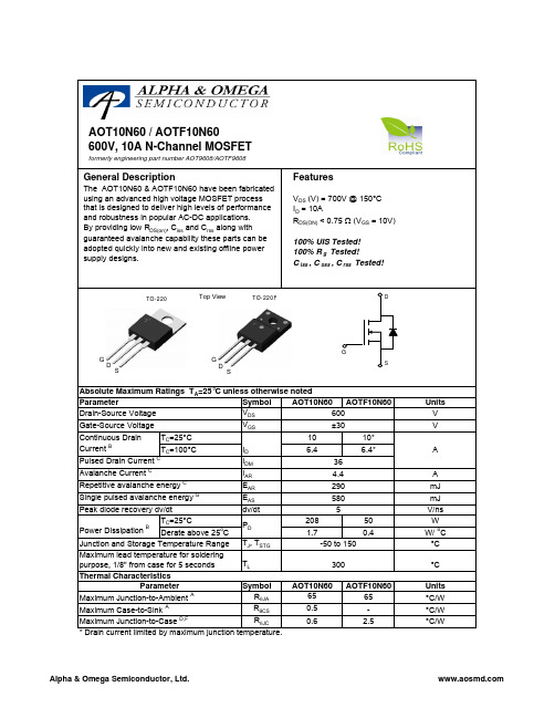
AOT9608中文资料
Continuous DrainParameter T =25°C Gate-Source Voltage Drain-Source Voltage Absolute Maximum Ratings T =25°C unless otherwise notedAOT10N60 / AOTF10N60DSDSSymbolMin Typ Max Units600V 700V BV DSS /∆T J 0.65V/ oC 110I GSS ±100nA V GS(th)345V R DS(ON)0.60.75Ωg FS 15S V SD 0.731V I S 10A I SM36A C iss 110013201600pF C oss 105130160pF C rss 7.59.311pF R g33.86ΩQ g 31.140nC Q gs 6.410nC Q gd 14.420nC t D(on)2835ns t r 6680ns t D(off)7695ns t f 6480ns t rr 290350ns Q rr3.94.7µC4.4THIS PRODUCT HAS BEEN DESIGNED AND QUALIFIED FOR THE CONSUMER MARKET. APPLICATIONS OR USES AS CRITICAL COMPONENTS IN LIFE SUPPORT DEVICES OR SYSTEMS ARE NOT AUTHORIZED. AOS DOES NOT ASSUME ANY LIABILITY ARISING OUT OF SUCH APPLICATIONS OR USES OF ITS PRODUCTS. AOS RESERVES THE RIGHT TO IMPROVE PRODUCT DESIGN,FUNCTIONS AND RELIABILITY WITHOUT NOTICE.V DS =480V, T J =125°C Breakdown Voltage Temperature CoefficientI D =250µA, V GS =0V Gate Threshold VoltageV DS =V GS , I D =250µA V DS =600V, V GS =0V V DS =0V, V GS =±30V Zero Gate Voltage Drain Current Gate-Body leakage current Body Diode Reverse Recovery TimeI D =250µA, V GS =0V, T J =25°C V GS =10V, I D =5A Reverse Transfer Capacitance I F =10A,dI/dt=100A/µs,V DS =100VV GS =0V, V DS =25V, f=1MHz SWITCHING PARAMETERS I DSS µA Maximum Body-Diode Pulsed CurrentElectrical Characteristics (T J =25°C unless otherwise noted)STATIC PARAMETERS Parameter Conditions Static Drain-Source On-Resistance Forward TransconductanceDiode Forward Voltage I S =1A, V GS =0V V DS =40V, I D =5ATurn-On Rise Time Turn-Off DelayTime V GS =10V, V DS =300V, I D =10A, R G =25ΩGate resistanceV GS =0V, V DS =0V, f=1MHzTurn-Off Fall TimeTotal Gate Charge V GS =10V, V DS =480V, I D =10AGate Source Charge Gate Drain Charge BV DSS Drain-Source Breakdown Voltage I D =250µA, V GS =0V, T J =150°C Body Diode Reverse Recovery Charge I F =10A,dI/dt=100A/µs,V DS =100VMaximum Body-Diode Continuous Current Input Capacitance Output Capacitance Turn-On DelayTime DYNAMIC PARAMETERS A: The value of R θJA is measured with the device in a still air environment with T A =25°C.B. The power dissipation P D is based on T J(MAX)=150°C, using junction-to-case thermal resistance, and is more useful in setting the upper dissipation limit for cases where additional heatsinking is used.C: Repetitive rating, pulse width limited by junction temperature T J(MAX)=150°C.D. The R θJA is the sum of the thermal impedence from junction to case R θJC and case to ambient.E. The static characteristics in Figures 1 to 6 are obtained using <300 µs pulses, duty cycle 0.5% max.F. These curves are based on the junction-to-case thermal impedence which is measured with the device mounted to a large heatsink, assuming a maximum junction temperature of T J(MAX)=150°C.G. L=60mH, I AS =4.4A, V DD =50V, R G =25Ω, Starting T J =25°CRev 0. July 2008VdsC ha rgeG ate Charge Test Circuit & W av eformResistiv e Switching Test Circuit & W av eformsVddVdsI dVgsB V I Unclamped Inductive Switching (UIS) Test Circuit & W av eformsARDSS2E = 1/2 LI VddARAR。
RZ8641(070929)

14
U02 U01
三角波 XR2206 正弦波 电 路 方波
K01
跟 随 放 大 器
P0
3
图2-1 非同步函数信号源结构示意图
15
2. 同步正弦波信号 它由2KHz方波信号源、低通滤波器和输出放大电路三部分组成。 2KHz方波信号由“时钟与基带数据发生模块”分频产生。U03及周边的阻容 网络组成一个截止频率为2KHZ的低通滤波器,用以滤除各次谐波,只输出一 个2KHz正弦波,在P04可测试其波形。用其作为PAM、PCM、ADPCM、CVSD(M) 等模块的音频信号源,其编码数据可在普通模拟示波器上形成稳定的波形, 便于实验者观测。 18W01用来改变输出同步正弦波的幅度。同步信号源结构示意图,见图2-2。 U04 4U0
6
第一部分 基础实验
实验1
555自激多谐振荡器实验
一、实验目的 1.了解555内部结构原理和逻辑功能; 2.掌握555构成的各种脉冲电路; 3.了解PAM抽样脉冲形成模块的使用方法和有关参数。 二、实验仪器 1.时钟与基带数据发生模块,位号:G 2.频率计1台 3.20M双踪示波器1台
1
U03
南京润众科技有限公司 整理
CPLD 器件
低通 滤波器
跟 随 放 大 器
P04
图2-2 同步函数信号源结构示意图
16
3. 模拟电话输入电路 本模块提供了两路用户模拟电话接口,图2-3是其电路结构示意图。J02A/ J02B是电话机的水晶头接口,U01是PBL38614专用电话集成电路。它的工作原理 是: (1) 当对电话机的送话器讲话时,该话音信号从PBL38614的TR对应的引脚输入, 经U01内部二四线转换处理后从T端输出。T端的模拟电话输出信号经P05/ P07铜 铆孔送出,可作为语音信号输出用。 (2) 当接收对方的话音时,送入U01芯片R端的输入信号可由P06/P08铜铆孔送入。 此时,在电话听筒中即可听到送入信号的声音。
BTA40,BTA41,BTB4-可控硅 中文自翻资料
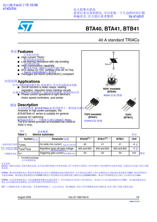
Symbol 符号
IT(RMS)
Parameter 参数
On-state rms current 通态均方根电流 TOP3
(full sine wave)
(全正弦波)
RD91 / TOP ins.
通态不重复浪涌电流
ITSM
Non repetitive surge peak on-state current (full cycle, Tj initial = 25 °C)
表1 Table 1.
设备概要 Device summary
Symbol 符号
Parameter 参数
BTA40(1) 注1
BTA41(1) 注1
BTB41
单位 Unit
通态电流有效值 IT(RMS)
断态工作峰值电压Vdrm 反向工作峰值电压Vrrm
VDRM/VRRM
门极触发电流 IGT
On-state rms current 通态均方根电流
VRRM―反向重复峰值电压; 在控制极断路和额定结温的条件下, 可以重复加在可控硅上的交流电压。此电压小于反向最高测试电压100V。反向最高测试电压, 规定为反向漏电流急速增加, 反向特性曲线开始弯曲时的电压。
IGT―门极触发电流; 在额定结温、在阳极和阴极加上一定正向电压(一般为6V)时, 保证元件从阻断状态到导通状态, 加在门极上的最大触发电流。
最后翻译编辑于15-10-06 a1a2x3编
众人拾柴火焰高
希望后来完善的朋友, 可以更新一下左边的时间日期
和编者名, 以方便后来者整理
by:a1a2x3
BTA40, BTA41, BTB41
40 A standard TRIACs
特征 Features
SMMBT2222ALT1G;SMMBT2222ALT3G;中文规格书,Datasheet资料
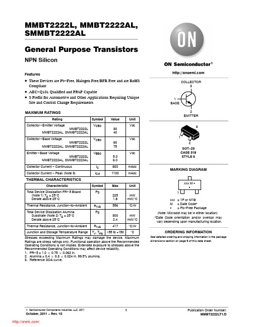
Collector Cutoff Current (VCB = 50 Vdc, IE = 0) (VCB = 60 Vdc, IE = 0) (VCB = 50 Vdc, IE = 0, TA = 125°C) (VCB = 60 Vdc, IE = 0, TA = 125°C)
MMBT2222 MMBT2222A, SMMBT2222A
MMBT2222L, MMBT2222AL, SMMBT2222AL
General Purpose Transistors
NPN Silicon
Features
• These Devices are Pb−Free, Halogen Free/BFR Free and are RoHS
Compliant
MMBT2222 MMBT2222A, SMMBT2222A
MMBT2222 MMBT2222A, SMMBT2222A
MMBT2222 MMBT2222A, SMMBT2222A
MMBT2222A, SMMBT2222A MMBT2222A, SMMBT2222A
MMBT2222A, SMMBT2222A MMBT2222A, SMMBT2222AIC6来自0mAdcICM
1100
mAdc
Characteristic
Total Device Dissipation FR− 5 Board (Note 1) TA = 25°C Derate above 25°C
Symbol PD
Max
225 1.8
Unit
mW mW/°C
Thermal Resistance, Junction−to−Ambient
MMBT2222A, SMMBT2222A MMBT2222A, SMMBT2222A
2SD864中文资料
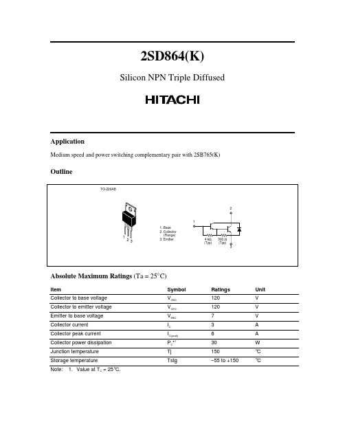
2SD864(K)Silicon NPN Triple DiffusedApplicationMedium speed and power switching complementary pair with 2SB765(K)OutlineTO-220AB4 k Ω(Typ)300 Ω(Typ)1231. Base2. Collector (Flange)3. Emitter123Absolute Maximum Ratings (Ta = 25°C)ItemSymbol Ratings Unit Collector to base voltage V CBO 120V Collector to emitter voltage V CEO 120V Emitter to base voltage V EBO 7V Collector current I C 3A Collector peak current I C(peak)6A Collector power dissipation P C *130W Junction temperature Tj 150°C Storage temperature Tstg–55 to +150°CNote:1.Value at T C = 25°C.2SD864(K)2Electrical Characteristics (Ta = 25°C)ItemSymbolMin Typ Max Unit Test conditions Collector to emitter breakdown voltageV (BR)CEO 120——V I C = 25 mA, R BE = _Emitter to base breakdown voltageV (BR)EBO 7——V I E = 50 mA, I C = 0Collector cutoff current I CBO ——100µA V CB = 120 V, I E = 0I CEO ——10µAV CE = 100 V, R BE = _DC current transfer ratio h FE 1000—20000V CE = 3 V, I C = 1.5 A*1Collector to emitter saturation voltageV CE(sat)1—— 1.5V I C = 1.5 A, I B = 3 mA*1V CE(sat)2—— 3.0V I C = 3 A, I B = 30 mA*1Base to emitter saturation voltage V BE(sat)1—— 2.0V I C = 1.5 A, I B = 3 mA*1V BE(sat)2—— 3.5V I C = 3 A, I B = 30 mA*1Turn on time t on —0.5—µs I C = 1.5 A, I B1 = –I B2 = 3 mAStorage time t stg — 4.5—µs Fall time t f—1.1—µs Note:1.Pulse test.2SD864(K)350100150Case temperature T C (°C)C o l l e c t o r p o w e r d i s s i p a t i o n P c (W )Maximum Collector Dissipation Curve 153045Area of Safe Operation0.010.030.10.31.0310Collector to emitter Voltage V CE (V)C o l l e c t o r C u r r e n t I C (A )1310301003001,000i C (peak)I Cmax(Continuous) 1 µs 100 µs 1 m s D COp e r at i o n (T C = 25°C )P W= 10 m s Ta = 25°C 1 shot pulse Collector to emitter voltage V CE (V)C o l l e c t o r c u r r e n t I C (A )Typical Output Characteristics1234512345T C = 25°CI B = 00.15 A0.20.30.40.250.350.451003001,0003,00010,00030,000100,000Collector current I C (A)D C c u r r e n t t r a n s f e r r a t i o h F E0.10.3 1.0310DC Current Transfer Ratio vs. Collector CurrentT a= 75°C 25°C –25°C V CE = 3 V Pulse2SD864(K)40.10.20.51.02510Collector current I C (A)0.10.20.5 1.02510CollectortoemittersaturationvoltageVCE(sat)(V)BasetoemittersaturationvoltageVBE(sat)(V)Saturation Voltage vs. Collector CurrentV BE(sat)V CE(sat)l C/l B = 500200T C = 25°C0.010.030.10.31.0310Collector current I C (A)Switchingtimet(µs)0.10.3 1.0310Switching Time vs. Collector CurrentTa = 25°CV CC = 30 VI C = 500 I B1 = –500 I B2t ft ont stg0.010.030.10.31.0310Thermalresistanceθj-c(°C/W)1101001,000 (s)1101001,000 (ms)Transient Thermal ResistanceTime t1 to 1,000 ms1 to 1,000 sT C = 25°C2SD864(K)5When using this document, keep the following in mind:1.This document may, wholly or partially, be subject to change without notice.2.All rights are reserved: No one is permitted to reproduce or duplicate, in any form, the whole or part of this document without Hitachi’s permission.3.Hitachi will not be held responsible for any damage to the user that may result from accidents or any other reasons during operation of the user’s unit according to this document.4.Circuitry and other examples described herein are meant merely to indicate the characteristics and performance of Hitachi’s semiconductor products. Hitachi assumes no responsibility for any intellectual property claims or other problems that may result from applications based on the examples described herein.5.No license is granted by implication or otherwise under any patents or other rights of any third party or Hitachi, Ltd.6.MEDICAL APPLICATIONS: Hitachi’s products are not authorized for use in MEDICALAPPLICATIONS without the written consent of the appropriate officer of Hitachi’s sales company.Such use includes, but is not limited to, use in life support systems. Buyers of Hitachi’s products are requested to notify the relevant Hitachi sales offices when planning to use the products in MEDICAL APPLICATIONS.Hitachi, Ltd.Semiconductor & IC Div.Nippon Bldg., 2-6-2, Ohte-machi, Chiyoda-ku, Tokyo 100, Japan Tel: Tokyo (03) 3270-2111 Fax: (03) 3270-5109For further information write to: Hitachi America, Ltd. Semiconductor & IC Div. 2000 Sierra Point Parkway Brisbane, CA. 94005-1835 U S ATel: 415-589-8300 Fax: 415-583-4207 Hitachi Europe GmbHElectronic Components Group Continental Europe Dornacher Straße 3 D-85622 Feldkirchen MünchenTel: 089-9 91 80-0 Fax: 089-9 29 30 00Hitachi Europe Ltd.Electronic Components Div. Northern Europe Headquarters Whitebrook ParkLower Cookham Road MaidenheadBerkshire SL6 8YA United Kingdom Tel: 0628-585000 Fax: 0628-778322Hitachi Asia Pte. Ltd. 16 Collyer Quay #20-00 Hitachi Tower Singapore 0104 Tel: 535-2100 Fax: 535-1533Hitachi Asia (Hong Kong) Ltd. Unit 706, North Tower, World Finance Centre,Harbour City, Canton Road Tsim Sha Tsui, Kowloon Hong Kong Tel: 27359218 Fax: 27306071。
AQN311;AQN411;AQN611;ATA4806;AQP-HS-3040A;中文规格书,Datasheet资料
Compliance with RoHS Directive
ORDERING INFORMATION
AQN
AQ-N Solid State Relays
Load current 1: 10 A 2: 15 A 3: 20 A 4: 25 A 6: 40 A
Load voltage 1: 75 to 250 V AC, Zero-cross 2: 75 to 250 V AC, Random
Type
Zero-cross type
Random type
Load current 10A 15A 20A 25A 40A 10A 15A 20A 25A 40A
Load voltage 75 to 250V AC
75 to 250V AC
Part No. AQN111 AQN211 AQN311 AQN411 AQN611 AQN121 AQN221 AQN321 AQN421 AQN621
AQ-N
High capacity SSR up to 40A
with wide variation
AQ-N RELAYS
FEATURES
1. Five types available from 10A to 40A 2. Built-in varistor 3. Includes operation LED (red) 4. Dielectric voltage of 4,000V 5. 4 to 32V DC input voltage 6. Both zero-cross and random types available
AQN111L AQN111V
AQN211L AQN211V
AQN311L AQN311V
- 1、下载文档前请自行甄别文档内容的完整性,平台不提供额外的编辑、内容补充、找答案等附加服务。
- 2、"仅部分预览"的文档,不可在线预览部分如存在完整性等问题,可反馈申请退款(可完整预览的文档不适用该条件!)。
- 3、如文档侵犯您的权益,请联系客服反馈,我们会尽快为您处理(人工客服工作时间:9:00-18:30)。
Unit
V V V
D out Output Voltage C out Output Voltage
OPERATION VOLTAGE AND OPERATION CURRENT
Parameter
Supply Current at Normal Operation Mode Standby Current at Power Down Mode Operation Voltage between VDD and VN
ONE-CELL LI-ION BATTERY PROTECTION IC
FEATURES
Ideal for One-Cell Rechargeable Li-Ion Battery Packs High Accuracy Voltage Detection Low Current Consumption: 3μA Supply Current (Typical) 0.1μA Shutdown Current 3-Level Over Current Detection: Over-Current Level 1 /Over Current Level 2 / Short Circuit Wide Operating Temperature Range:
–
– 台灣類比科技股份有限公司 – Advanced Analog Technology, Inc. –
Page 1 of 25 V2.0
元器件交易网
Advanced Analog Technology, Inc.
AAT8641 Series
(Over-Discharge Release Voltage). Over Current Level 1 Voltage ( VOC1 ) is used to monitor the amount of discharge current. If the discharge current is high enough to cause VN pin voltage to be greater than VOC1 , the output of D out pin will switch to low level after a delay time tOC1. If the load is removed from battery pack, the output of D out will change to high again. The mechanism of short circuit protection is exactly the same as discharge current. If the short circuit current is high enough to cause VN pin voltage to be greater than Vshort , the output of D out pin would fall to low level after a delay time t short , and the output of D out level will change to high when the load is removed from battery pack.
Detect Rising Edge of “VN” Pin Voltage ( D out Response with t OC1 Delay Time) Detect Rising Edge of “VN” Pin Voltage ( D out Response with t OC 2 Delay Time)
Advanced Analog Technology, Inc.
AAT8641 Series
AAT8641A DETECTION VOLTAGE AND DELAY TIME (25℃)
PARAMETER
Over Charge Threshold Voltage Over Charge Release Voltage Over Discharge Threshold Voltage Over Discharge Release Voltage Over Charge Delay Time Over Discharge Delay Time Over Current Level 1 Detection Voltage Over Current Level 2 Detection Voltage
VALUE
−0.3 to 8.0 VDD − 20.0 to VDD + 0.3 −0.3 to VDD + 0.3 VVN − 0.3 to VDD + 0.3
UNIT
V V V V mW
o o
Power Dissipation Operating Temperature Range Storage Temperature Range
BLOCK DIAGRAM:
Dout
C out
–
– 台灣類比科技股份有限公司 – Advanced Analog Technology, Inc. –
Page 2 of 25 V2.0
元器件交易网
Advanced Analog Technology, Inc.
AAT8641 Series
ABSOLUTE MAXIMUM RATINGS
CHARACTERISTICS
Supply Voltage VN Pin Input Voltage
D out Pin Output Voltage C out Pin Output Voltage
SYMBOL
VDD VVN VDout VCout Pd TC
VDD = 3.0V , Detect Rising Edge of “VN” Pin Voltage ( D out Response with t short Delay Time) VDD = 3.0V
130
150
170
mV
VOC 2
400
500
600
mV
Short Circuit Detection Voltage Over Current Level 1 Detection Delay Time Over Current Level 2 Detection Delay Time Short Circuit Detection Delay Time Charger Detection Voltage
元器件交易网
Advanced Analog Technology, Inc.
AAT8641 Series
Product information presented is current as of publication date. Details are subject to change without notice
PIN DESCRIPTION
PIN NO
1 2 3 4 5
NAME
VN VDD GND D out
C out
I/O
I I O O
DESCRIPTION
Voltage Detection Pin Between VN and GND Power Supply Input Pin Ground Discharge Control Pin which Connects to External MOSFET Gate Charge Control Pin which Connects to External MOSFET Gate.
Test Condition
VDD =3.3V; VN=0V; GND=0V
Min
1.5
Typ
3.0 -
Max
5.0 0.1 20.0
Unit
μA μA
V
–
– 台灣類比科技股份有限公司 – Advanced Analog Technology, Inc. –
Page 3 of 25 V2.0
元器件交易网
SYMBOL
VC1 VC 2 VD1 VD 2 t C1 t D1 VOC1
TEST CONDITION
Detect Rising Edge of Supply Voltage Detect Falling Edge of Supply Voltage Detect Falling Edge of Supply Voltage Detect Rising Edge of Supply Voltage VDD = 3.6V to 4.5V
C to +85 oC
Small SOT25 Package
PIN CONFIGURATION
TOP VIEW
VN
COUT
GND
D OUT
Discharge Threshold Voltage), the output of D out pin switches to low level immediately after the internal delay time elapses. The output of D out pin will switch to high level when the battery voltage is at a level higher than VD 2
VDD = 3.6V to 2.4V
Min
4.300
Typ
4.325
Max
4.350
Unit
V V V V s ms
VC1 − 0.30 VC1 − 0.25 VC1 − 0.20
2.420 VD1+0.3 0.700 87.5
2.500 VD1+0.4 1.000 125.0
2.580 VD1+0.5 1.300 162.5
