KLCS-47E中文资料
赛米控模块 系列

SKB 25SKiiP 603 GD123-3DUL V3 SK20KDD12SCp Case G 10b(29x29x10)SKiiP3(280x215x156) SEMITOP 2 Press-Fit100-16001200(28x40.5x12)12001760018320Six PackH-Bridge4IGBT 3 (Trench)Sample status In production In productionSKiiP 13ACM12V17SKD 25SKiiP 603 GD123-3DUW V3 MiniSKiiP II 1(42x40x16)Case G 11b(29x29x10)SKiiP3(330x215x112) 1200200-160012002520600Six Pack320Six PackSample status6IGBT 3 (Trench)SKiiP 13ACM12V18In production In productionMiniSKiiP II 1(42x40x16)SKB 28SKiiP 613 GD123-3DUL V3 1200SEMIPONT 1(63x32x22)SKiiP3(280x215x156)25200-16001200Six Pack28600Sample status320Six PackSK25MH120SCTp4IGBT 3 (Trench)SEMITOP 2 Press-FitIn production In production(28x40.5x12)1200SKB 30SKiiP 613 GD123-3DUW V3 26G12(55x45x24)SKiiP3(330x215x112)H-Bridge200-16001200Sample status30600SK35MLLE120SCp320Six PackSEMITOP 2 Press-Fit4IGBT 3 (Trench)(28x40.5x12)1200In production In production36SKD 30SKiiP 1213 GB123-2DL V3 Customer Specific G13(55x45x24)SKiiP3(200x215x156) Sample status200-16001200SK45MAHT12SCp301200SEMITOP 3 Press-Fit320Half Bridge(31x55x12)12006IGBT 3 (Trench)39In production In productionSix Pack SKD 31SKiiP 1213 GB123-2DW V3 In production new SEMIPONT 1(63x32x22)SKiiP3(270x215x112)SK45MLET12SCp200-16001200SEMITOP 3 Press-Fit311200(31x55x12)1200320Half Bridge396IGBT 3 (Trench)Single Switch In production In productionSample status SKB 26SKiiP 1813 GB123-3DL V3SK45MH120TSCp Case G 50a(29x29x10)SKiiP3(280x215x156) SEMITOP 2 Press-Fit200-20001200(28x40.5x12)120018180040320Half BridgeH-Bridge4IGBT 3 (Trench)Sample status In production In productionSKKE60S12SKBZ 28SKiiP 1813 GB123-3DUL V3 SEMIPACK 2(94x34x30)SEMIPONT 1(63x32x22)SKiiP3(280x215x156) 1200400-1400120064281800Single Switch280Half BridgeSample status4IGBT 3 (Trench)SKiiP 26ACM12V17In production In productionMiniSKiiP II 2(59x52x16)SKCH 28SKiiP 1813 GB123-3DW V3 1200SEMIPONT 1(63x32x22)SKiiP3(330x215x112)72400-14001200Six Pack281800Sample status280Half BridgeSKM350MB120SCH155IGBT 3 (Trench) SEMITRANS 3(106x62x31)In production In production1200SKDT 60SKiiP 1814 GB12E4-3DULV2523SEMIPONT 2(65x48x36)SKiiP4(280x215x152)Half Bridge400-14001200Sample status601800SKM350MB120SCH17400Half BridgeSEMITRANS 3(106x62x31)6IGBT 4 (Trench)1200In production In production523SKD 26SKiiP 1814 GB12E4-3DUWV2Half Bridge G50b(29x29x10)SKiiP4(290x215x102) Sample status400-16001200SKM500MB120SC201800SEMITRANS 3(106x62x31)320Half Bridge12006IGBT 4 (Trench)541In production In productionHalf Bridge SKB 35SKiiP 2413 GB123-4DL V3 Sample status Case G 10b(29x29x10)SKiiP3(360x215x156)SKiiP25AC12F4V19400-16001200MiniSKiiP II 2(59x52x16)3524001200330Half Bridge504IGBT 3 (Trench)Six Pack In production In productionSKD 35SKiiP 2413 GB123-4DUL V3 SiC Diode + IGBT 4 fast(Trench)Sample status Case G 11b(29x29x10)SKiiP3(360x215x156)SKiiP38AC12F4V19400-16001200MiniSKiiP II 3(82x59x16)3624001200320Half Bridge1006IGBT 3 (Trench)Six Pack In production In productionSKCH 40SKiiP 2413 GB123-4DW V3 SiC Diode + IGBT 4 fast(Trench)Sample status SEMIPONT 2(65x48x36)SKiiP3(390x215x112)SK150MLIB12F4TSCE2400-16001200SEMITOP E2(63x57x12)4024001200400Half Bridge1505IGBT 3 (Trench)Customer Specific In production In productionIGBT 4 Fast (Trench)SKB 60SKiiP 2414 GB12E4-4DUL Sample status SEMIPONT 2(65x48x36)SKiiP4(360x215x152)SK150MLIT12F4TSCE2400-16001200SEMITOP E2(63x57x12)6024001200850Half Bridge1504IGBT 4 (Trench)Customer Specific In production In productionIGBT 4 Fast (Trench)SKD 60SKiiP 2414 GB12E4-4DUW Sample status SEMIPONT 2(65x48x36)SKiiP4(350x215x102)SKiiP39AC12F4V19400-16001200MiniSKiiP II 3(82x59x16)6024001200850Half Bridge1506IGBT 4 (Trench)Six Pack In production In productionSKD 100SKiiP 3614 GB12E4-6DUL SiC Diode + IGBT 4 fast(Trench)Sample status SEMIPONT 2(65x48x36)SKiiP4(470x215x152)SKM200GB12F4SiC2400-16001200SEMITRANS 3(106x62x31)100360012001000Half Bridge2006IGBT 4 (Trench)Half Bridge In production In productionBI 6SKiiP 3614 GB12E4-6DUW SiC Diode + IGBT 4 fast(Trench)Sample status DBI(40x20x10)SKiiP4(480x215x102)SKM200GB12F4SiC3400-18001200SEMITRANS 3(106x62x31)936001200165Half Bridge2004IGBT 4 (Trench)Half Bridge In production In productionDBI 6SKiiP 513 GD172-3DUL V3 SiC Diode + IGBT 4 fast(Trench)Sample status DBI(40x20x10)SKiiP3(280x215x156)SKM200GB12T4SiC2400-18001700SEMITRANS 3(106x62x31)95001200150Six Pack2006IGBT 3 (Trench)Half Bridge In production In productionSiC Diode + IGBT 4 (Trench)BI 25SKiiP 513 GD172-3DUW V3Sample status DBI(40x20x10)SKiiP3(330x215x112)SKiiP 38GB12F4V19400-18001700MiniSKiiP II 3(82x59x16)255001200310Six Pack3004IGBT 3 (Trench)Half Bridge In production In productionIGBT 4 Fast (Trench)top20 / 98top20 / 61Sample status DBI 25SKiiP 603 GD172-3DUL V3 SKiiP39MLIB12F4V22DBI(40x20x10)SKiiP3(280x215x156) MiniSKiiP II 3(82x59x16)400-18001700120025570400310Six PackCustomer Specific6IGBT 3 (Trench)IGBT 4 Fast (Trench)In production In productionSample status SKD 33SKiiP 603 GD172-3DUW V3 SKiiP39MLIT12F4V22G55(63.5x29.5x17)SKiiP3(330x215x112) MiniSKiiP II 3(82x59x16)400-18001700120033570400240Six PackCustomer Specific6IGBT 3 (Trench)IGBT 4 Fast (Trench)In production In productionSample status SKB 52SKiiP 1013 GB172-2DL V3 SKiM459GD12F4V3SEMIPONT 3(72x42x30)SKiiP3(200x215x156)SKIM 93(160x150x35)400-180017001200501000450425Half BridgeSix Pack4IGBT 3 (Trench)SiC Diode + IGBT 4 fast(Trench)In production In productionSample status SKD 51SKiiP 1013 GB172-2DW V3 SKiM459GD12F4V4G51(90x29x18)SKiiP3(270x215x112)SKIM 93(160x150x35)400-180017001200501000450700Half BridgeSix Pack6IGBT 3 (Trench)SiC Diode + IGBT 4 fast(Trench)In production In productionSample status SKD 53SKiiP 1203 GB172-2DL V3 SEMiX603GB12E4SiCp G55(63.5x29.5x17)SKiiP3(200x215x156)SEMiX 3p(150x62x17)400-180017001200531200600270Half BridgeHalf Bridge6IGBT 3 (Trench)SiC Diode + IGBT 4 (Trench)In production In productionSample status SKD 62SKiiP 1203 GB172-2DW V3 SK300MB080SEMIPONT 3(72x42x30)SKiiP3(270x215x112) SEMITOP 3(55x31x12)400-1800170080601200317425Half BridgeHalf Bridge6IGBT 3 (Trench)Sample status In production In productionSK 85 MH 10 T SKB 72SKiiP 1513 GB172-3DFL V3 SEMITOP 2(41x28x12)SEMIPONT 3(72x42x30)SKiiP3(280x215x156) 100400-1800170080701500H-Bridge640Half BridgeNot for new designs4IGBT 3 (Trench)SKM 111 AR In production In productionSEMITRANS M1 (80x42x30)SKD 82SKiiP 1513 GB172-3DL V3100SEMIPONT 3(72x42x30)SKiiP3(280x215x156) 200400-18001700Single Switch801500In production640Half BridgeSKM 111 RZR6IGBT 3 (Trench)SEMITRANS M1 (80x42x30)In production In production100SKD 83SKiiP 1513 GB172-3DW V3 200G55(63.5x29.5x17)SKiiP3(330x215x112)Single Switch400-18001700In production831500SK280MB10560Half BridgeSEMITOP 3(55x31x12)6IGBT 3 (Trench)100In production In production278DBI 6 P SKiiP 1803 GB172-3DL V3 Half Bridge DBI(40x22x7)SKiiP3(280x215x156) Sample status400-22001700SKM 180 A02091800SEMITRANS M1 (80x42x30)165Half Bridge2006IGBT 3 (Trench)180In production In productionSingle Switch BI 6 P SKiiP 1803 GB172-3DW V3 In production DBI(40x22x7)SKiiP3(330x215x112)SK50MH65TE1400-22001700SEMITOP E1(63x34x12)101800650165Half Bridge554IGBT 3 (Trench)Customer Specific In production In productionSample status BI 25 P SKiiP 1814 GB17E4-3DULV2SK300MB080DBI(40x22x7)SKiiP4(280x215x152) SEMITOP 3(55x31x12)400-2200170080251800317310Half BridgeHalf Bridge4IGBT 4 (Trench)Sample status In production DiscontinuedSK 85 MH 10 T DBI 25 P SKiiP 1814 GB17E4-3DUWV2SEMITOP 2(41x28x12)DBI(40x22x7)SKiiP4(290x215x102)100400-22001700 80271800H-Bridge310Half BridgeNot for new designs6IGBT 4 (Trench) SKM 111 AR In production In productionSEMITRANS M1 (80x42x30)SK 50 B 06 UF SKiiP 2013 GB172-4DFL V3100SEMITOP 2(41x28x12)SKiiP3(360x215x156) 2006001700Single Switch462000In production400Half BridgeSKM 111 RZR4IGBT 3 (Trench)SEMITRANS M1 (80x42x30)In production In production100SK 55 B 06 F SKiiP 2013 GB172-4DL V3 200SEMITOP 2(41x28x12)SKiiP3(360x215x156)Single Switch6001700In production542000SK280MB10440Half BridgeSEMITOP 3(55x31x12)4IGBT 3 (Trench)100In production In production278SK 200 DHL 066SKiiP 2013 GB172-4DW V3 Half Bridge SEMITOP 4(61x55x12)SKiiP3(390x215x112) Sample status6001700SKM 180 A020*******SEMITRANS M1 (80x42x30)1250Half Bridge2007IGBT 3 (Trench)180Sample status In productionSingle Switch SKBH 28SKiiP 2403 GB172-4DL V3 In production SEMIPONT 1(63x32x22)SKiiP3(360x215x156)SK50MH65TE1600-14001700SEMITOP E1(63x34x12)282400650280Half Bridge554IGBT 3 (Trench)Customer Specific In production In productionSample status SKBT 28SKiiP 2403 GB172-4DW V3 SKKH 15SEMIPONT 1(63x32x22)SKiiP3(390x215x112) SEMIPACK 0(61x21x25)600-14001700600-160028240013.5280Half Bridge2804IGBT 3 (Trench)2In production In productionIn production SK40BBB07TD1E2SKiiP 2414 GB17E4-4DPVL SKKT 15SEMITOP E2(63x57x12)SKiiP4(360x215x152) SEMIPACK 0(61x21x25)6501700600-160042240013.5t.b.d.Half Bridge280Sample status IGBT 4 (Trench)2SK70B07TD1E1In productionIn production SEMITOP E1(63x34x12)SKiiP 2414 GB17E4-4DPVWSKKD 15650SKiiP4(350x215x102) SEMIPACK 0(61x21x25)681700600-1600560240014Sample status Half Bridge280top40 / 98IGBT 4 (Trench)2SKBT 40In productionIn production SEMIPONT 2(65x48x36)top40 / 61SKKE 15800-1400SKiiP 2414 GB17E4-4DULV2SEMIPACK 0(61x21x25)40SKiiP4(360x215x152)600-160040017001442400280In production Half Bridge1SKDH 100IGBT 4 (Trench)In production SEMIPONT 2(65x48x36)In productionSKKT 20800-1400SKiiP 2414 GB17E4-4DUWV2SEMIPACK 1(93x20x30)100SKiiP4(350x215x102)800-160085017001862400280In production Half Bridge2SK 40 DH IGBT 4 (Trench)In production SEMITOP 3(55x31x12)In productionSKKT 20B800-1600SKiiP 3614 GB17E4-6DPVL SEMIPACK 1(93x20x30)42SKiiP4(470x215x152)800-160027017001863600280In production Half Bridge2SK 40 DT IGBT 4 (Trench)In production SEMITOP 3(55x31x12)In productionSK 30 DTA800-1600SKiiP 3614 GB17E4-6DPVLRSEMITOP 3(55x31x12)42SKiiP4(470x215x152)800-160028017002563600900In production Half Bridge7SK 50 B IGBT 4 (Trench)In production SEMITOP 2(41x28x12)DiscontinuedSKKT 27800-1600SKiiP 3614 GB17E4-6DULV2SEMIPACK 1(93x20x30)51SKiiP4(470x215x152)800-160027017002543600480In production Half Bridge2SK 55 D IGBT 4 (Trench)In production SEMITOP 2(41x28x12)In productionSKKT 27B800-1600SKiiP 3614 GB17E4-6DUWV2SEMIPACK 1(93x20x30)55SKiiP4(480x215x102)800-160020017002563600480In production Half Bridge2SK 70 B IGBT 4 (Trench)In production SEMITOP 2(41x28x12)In productionSKKH 27800-1600SKiiP3 F-Option SEMIPACK 1(93x20x30)68SKiiP Utilities800-1800560-254-480In production No switches2SK 70 DH-In production SEMITOP 3(55x31x12)In productionSK 25 KQ800-1600SKiiP3 Parallel Board 2-foldSEMITOP 1(31x24x12)68SKiiP Utilities800-1600270-296-280In production No switches2SK 70 DT-In production SEMITOP 3(55x31x12)In productionSK 25 UT800-1600SKiiP3 Parallel Board 3-foldSEMITOP 3(55x31x12)68SKiiP Utilities800-1600380-296-280In production No switches6SK 70 D-In production SEMITOP 2(41x28x12)In productionSK 25 WT800-1600SKiiP3 Parallel Board 4-foldSEMITOP 2(41x28x12)70SKiiP Utilities800-1600270-296-280In production No switches4SK 95 D-In production SEMITOP 2(41x28x12)In productionSK25UT16p800-1600SKiiP4 F-Option SEMITOP 3 Press-Fit(31x55x12)95SKiiP Utilities1600560-296-280In production No switches6SK 100 B-Sample status SEMITOP 2(41x28x12)In productionSKKD 26800-1600SKiiP4 F-Option (D-Sub connector, no case)SEMIPACK 1(93x20x30)100SKiiP Utilities 1200-1600890-314-480In production No switches2SKD 110-In production SEMIPONT 4(94x54x32)In production newSK 35 BZ800-1800SKiiP4 F-Option with D-Sub connectorSEMITOP 2(41x28x12)110SKiiP Utilities800-16001000-356-270In production No switches 4SKD 160-In production new SEMIPONT 4(94x54x32)In productionSK 35 TAA800-1800SKiiP4 Parallel Board 2-fold F-OptionSEMITOP 2(41x28x12)205SKiiP Utilities 800-16001500-356-380In production No switches 2SKD 210-In production new SEMIPONT 4(94x54x32)In productionSKKD 40F900-1800SKiiP4 Parallel Board 2-fold without F-OptionSEMIPACK 1 Fast (93x20x30)207SKiiP Utilities600-10001600-406-940In production No switches 2SK150DGL12T4-In production SEMITOP 3(55x31x12)In productionSKKH 421200SKiiP4 Parallel Board 3-fold F-OptionSEMIPACK 1(93x20x30)49SKiiP Utilities 800-18007-40Sample status-850SK 55 DGL 126No switches 2SEMITOP 3(55x31x12)-In production1200In productionSKKT 4255SKiiP4 Parallel Board 3-fold without F-OptionSEMIPACK 1(93x20x30)370SKiiP Utilities 800-18007-40In production-850SK 55 B 12 F No switches 2SEMITOP 2(41x28x12)-In production1200In productiontop20 / 14957SKiiP4 Parallel Board 4-fold F-OptionSKKT 42B550SKiiP Utilities SEMIPACK 1(93x20x30)4-800-1800In production-40SK 80 D 12F No switches 850SEMITOP 3(55x31x12)-21200In productionIn production80SKiiP4 Parallel Board 4-fold without F-OptionSKWT 40550SKiiP Utilities SEMIPONT 1 (63x32x22)6-800-2200Discontinued-40SKD 146/12-L140No switches 580SEMIPONT 6 (100x45x17)-Sample status 1200In productionSKKD 42F140SKiiP4 SKiFace Adapter Temp SEMIPACK 1 Fast(93x20x30)1250SKiiP Utilities 1200-14006-42In production new -1100top 60 / 98No switches 2SK 170 DHL 126-In production SEMITOP 4 (61x55x12)In production SK 45 KQ 1200top 60 / 61SEMITOP 1 (31x24x12)170SKiiP4 SKiFace Adapter UZK 800-16001000SKiiP Utilities 477-380Sample status -2SEMiX251D12Fs No switches In production SEMiX 13 (138x71x17)-SK 45 STA 1200In production SEMITOP 3 (55x31x12)256SKHIT 01 R 800-16001330Driver 476528380Not for new designs -6SKD 35 AV -In production Case G 11b (29x29x10)3SK 45 UT 1200-1600In production SEMITOP 3 (55x31x12)39SKHI 61 R 800-1600345Driver Core 476900380In production 26SKD 116/..-L1051In production SEMIPONT 6 (100x45x17)6SK 45 WT 1200-1600Discontinued SEMITOP 2 (41x28x12)110SKHI 71 R 800-16001050Driver Core 476900380In production new 24SKD 116/..-L1401In production SEMIPONT 6 (100x45x17)7SKKD 461200-1600Discontinued SEMIPACK 1 (93x20x30)110SKHI 10/12 R 800-18001050Driver 4761200600In production new 82SKDH 1159.6In production SEMIPONT 5(81x46x17)1SK45WT12p1200-1600In productionSEMITOP 2 Press-Fit (28x40.5x12)110SKHI 21A R1200950Driver Core4761200380In production84SKDH 116/..L1054In production new SEMIPONT 6(100x45x17)2SKKH 571200-1600In productionSEMIPACK 1(93x20x30)110SKHI 22 A/B R800-18001000Driver Core50612001250In production new82SKDH 116/..L1404In production SEMIPONT 6(100x45x17)2SKKT 571200-1600DiscontinuedSEMIPACK 1(93x20x30)110SKHI 23/12 R800-18001000Driver50612001250In production new82SKDT 115 4.8In production SEMIPONT 5(81x46x17)2SKKT 57B1200-1600In productionSEMIPACK 1(93x20x30)110SKYPER 12 press-fit 300A 800-1800950Driver50612001250Not for new designs152SKD 146/..-L1058In production SEMIPONT 6(100x45x17)2SKKH 57 H41200-1600In productionSEMIPACK 1(93x20x30)140SKYPER 12 press-fit 450A 2000-22001250Driver50612001250In production new152SKD 146/..-L140T48In production SEMIPONT 6(100x45x17)2SKKT 57 H41200-1600In productionSEMIPACK 1(93x20x30)140SKYPER 12 press-fit 600A 2000-22001250Driver50612001250In production new152SKDH 146/..-L1058In production SEMIPONT 6(100x45x17)2SK 55 TAA1200-1600In productionSEMITOP 2(41x28x12)140SKYPER 12 press-fit C300A800-16001250Driver5561200900In production new152SKDH 146/..-L1408In production SEMIPONT 6(100x45x17)2SKKH 58/16 E1200-1600In production SEMIPACK 1(93x20x30)140SKYPER 12 press-fit C450A16001250Driver55612001200In production new152SKDH 1458In production SEMIPONT 5(81x46x17)2SKKT 58/16 E1200-1600In production SEMIPACK 1(93x20x30)145SKYPER 12 press-fit C600A16001250Driver55612001200In production152SKDT 1458In production SEMIPONT 5(81x46x17)2SKKT 58B16 E1200-1600In productionSEMIPACK 1(93x20x30)145SKYPER PRIME 1400A / 1200V PP16001250Driver55612001200In production152SKD 11510In production SEMIPONT 5(81x46x17)2SKKD 60F1200-1800In production newSEMIPACK 2 Fast (94x34x30)110SKYPER PRIME 1400A /1200V ST1017001150Driver6061200900In production152SKD 1457.5In production SEMIPONT 5(81x46x17)2SK 60 DTA1200-1800In production newSEMITOP 3(55x31x12)145SKYPER PRIME O 1400A / 1200V PP800-16001700Driver61612001350In production157SK 40 BHL 066T10In production SEMITOP 3(55x31x12)2top40 / 1491600In production newSK 80 DTA42SKYPER PRIME O 1400A / 1200V ST10SEMITOP 3(55x31x12)280Driver 800-1600In production new120065SKiiP 28AHB16V1151800MiniSKiiP II 2(59x52x16)7.5716002In production82In production newSKKH 721000Board 2 // 4S SKYPER 42 R SEMIPACK 1(93x20x30)7Adapter Board800-1800In production120070SKiiP 28ANB16V1301450MiniSKiiP II 2(59x52x16)50216002In production83In productionSKKT 721000SKHI 10/17 RSEMIPACK 1(93x20x30)7Driver800-1800In production170070top80 / 9881450SKiiP 28ANB16V29.62MiniSKiiP II 2(59x52x16)1In production1600In productionSKKT 72B83SKHI 22 A/B H4 R SEMIPACK 1(93x20x30)1000Driver Core800-18007170070In production81450SKiiP 28ANB16V1042MiniSKiiP II 2(59x52x16)2In production1600In productionSKKH 72 H483top20 / 54SEMIPACK 1(93x20x30)1000SKHI 23/17 R2000-22007Driver70In production17001450SK 95 D 16p82SEMITOP 2 Press-Fit(28x40.5x12)4.8In production16002SKKT 72 H495In productionSEMIPACK 1(93x20x30)560Board 1 SKYPER 32PRO R 2000-22006Adapter Board70In production new17001450SK 95 DGL 126152SEMITOP 3(55x31x12) 6.3In production16002SK 70 KQ96In productionSEMITOP 1(31x24x12)700Board 1 SKYPER 32 R800-16007Adapter Board72In production1700900SK140B16TE1152SEMITOP E1(63x34x12) 2.5In production16002SK 70 WT100In productionSEMITOP 3(55x31x12)Sample status Board 2S SKYPER 32 PRO R Gold800-1600SKiiP 39AHB16V1Adapter Board72MiniSKiiP II 3(82x59x16)17009001600154121 6.3In production12502SK 75 TAA7In production SEMITOP 2(41x28x12)In production Board 2S SKYPER 32 RGold800-1600SKiiP 39ANB16V1Adapter Board75MiniSKiiP II 3(82x59x16)170015001600152124 2.5In production new16002SK 75 TAE 127In productionSEMITOP 2(41x28x12)In production Board 3S SKYPER 32 PRO R Gold1200SKD 146/16Adapter Board 75SEMIPONT 6(100x45x17)1700 12501600152140 6.3In production12502SKKD 75F126In productionSEMIPACK 2 Fast (94x34x30)In production new Board 3S SKYPER 32 RGold1200SKD 146/16Adapter Board 75SEMIPONT 6(100x45x17)1700 9001600152140 2.5In production12502SKKE 816In productionSEMIPACK 1(93x20x30)In production new Board 4S SKYPER 32 PRO R Gold800-1600SKD 146/16-L140Adapter Board82SEMIPONT 6(100x45x17)170017501600151140 6.3In production12502SKKD 816In production SEMIPACK 1(93x20x30)In production Board 4S SKYPER 32 RGold800-1800SEMiX291D16s Adapter Board82SEMiX 13(138x71x17)170017501600152232 2.5In production13802SKKD 81 H46In production SEMIPACK 1(93x20x30)In production SKHI 24 R2000-2200SEMiX241DH16s Driver Core82SEMiX 13(138x71x17)1700 175016001522985In production18002SKUT 85/12 V26In productionSEMIPONT 5(81x46x17)In production SKYPER 12 press-fit 450A 1700V1200SEMiX245DH16Driver85SEMiX 5p(130x70x17)1700 105016001563368In production new18002SKUT 85/16 V26In productionSEMIPONT 5(81x46x17)In production new SKYPER 12 press-fit 600A 1700V1600SEMiX341D16s Driver85SEMiX 13(138x71x17)1700 105016001563488In production new20002SKUT 85/12 T V26In productionSEMIPONT 5(81x46x17)In production SKYPER 12 press-fit C 450A 1700V1200SEMiX365DH16Driver94SEMiX 5p(130x70x17)1700 105016001564848In production new27502SKUT 85/16 T V26In productionSEMIPONT 5(81x46x17)In production new SKYPER 12 press-fit C 600A 1700V1600SEMiX501D17Fs Driver94SEMiX 13(138x71x17)1700105017001564948In production new21402SKKH 926In production SEMIPACK 1(93x20x30)In production SKYPER 32 PRO R 800-1800SKiiP 28ANB18V3Driver Core95MiniSKiiP II 2(59x52x16)17001750180015298 6.3In production10002SKKL 927In production SEMIPACK 1(93x20x30)In production new SKYPER 32 R800-1800SKD 116/18-L 75Driver Core95SEMIPONT 6(100x45x17)170017501800152110 2.5In production10502top60 / 1496In productionSKKT 92In production SKYPER PRIME 1000A / 1700V PPSEMIPACK 1(93x20x30)SKB 25Driver800-1800Case G 10b(29x29x10)170095100-1600151750171023202In production4In production newSKKT 92BIn production SKYPER PRIME 1000A / 1700V ST10SEMIPACK 1(93x20x30)SKD 25Driver800-1800Case G 11b(29x29x10)170095200-160015175020723202In production6In production newSKMT 92In production SKYPER PRIME 1400A / 1700V PPSEMIPACK 1(93x20x30)SKB 28Driver800-1800SEMIPONT 1(63x32x22)170095200-16001517502813.523202In production4In production newSKKD 100In production SKYPER PRIME 1400A / 1700V ST10SEMIPACK 1(93x20x30)SKB 30Driver400-1800G12(55x45x24)1700100200-1600152000301023202In production4In production new SK 100 TAA In production top40 / 54SEMITOP 2(41x28x12)SKD 30SKYPER PRIME O 1000A /1700V PP800-1600G13(55x45x24)Driver100200-1600170020003015232010In production new62SK100TAA16p In production In production newSEMITOP 2 Press-Fit (28x40.5x12)SKD 31SKYPER PRIME O 1000A /1700V ST101600SEMIPONT 1(63x32x22)Driver100200-160017001800311523207Sample status62SK 100 KQ In production In production newSEMITOP 2(41x28x12)SKB 26SKYPER PRIME O 1400A /1700V PP800-1600Case G 50a(29x29x10)Driver101200-2000170013501815232013.5In production42SK 100 WT In production In production newSEMITOP 3(55x31x12)SKBZ 28SKYPER PRIME O 1400A /1700V ST10800-1600SEMIPONT 1(63x32x22)Driver101400-1400170013502815428010In production42SKUT 115/12 V2In production In production new SEMIPONT 5(81x46x17)SKCH 28SKYPER 12 PV R 1200SEMIPONT 1(63x32x22)Driver Core 105400-1400170012502820628020In production new52SKKD 105F In production In production newSEMIPACK 1 Fast (93x20x30)SKDT 60SKYPER 12 R1200-1600SEMIPONT 2(65x48x36)Driver Core105400-1400170021006020240020In production62SKUT 115/16 V2In production In production new SEMIPONT 5(81x46x17)SKD 26SKYPER 42 LJ R1600G50b(29x29x10)Driver Core105400-1600170012502024632020In production new62SKKH 106In production In productionSEMIPACK 1(93x20x30)SKB 35SKYPER 42 LJ R (coated) 800-1800Case G 10b(29x29x10)Driver Core106400-1600170019003524233020In production42SKKT 106In production In production new SEMIPACK 1(93x20x30)SKD 35Board 2//3S SKYPER 42 R 800-1800Case G 11b(29x29x10)Adapter Board106400-1600170019003630232050In production62SKKT 106B In production In productionSEMIPACK 1(93x20x30)SKCH 40Board 2 generic SKYPER42 R800-1800SEMIPONT 2(65x48x36)Adapter Board106400-1600170019004030240050In production52SKKD 115F14In production In productionSEMIPACK 1 Fast (93x20x30)SKB 60Board 63 GB SKYPER 42 R1400SEMIPONT 2(65x48x36)Adapter Board115400-1600170021006030285050In production42SKKH 107/16 E In production In productionSEMIPACK 1(93x20x30)SKD 60Board 93 GB SKYPER 42 R 1600SEMIPONT 2(65x48x36)Adapter Board119400-1600170019006030285050In production62SKKT 107/16 E In production In production new SEMIPACK 1(93x20x30)SKD 100SKYPER 42 R1600SEMIPONT 2(65x48x36)Driver Core119400-160017001900100302100050In production62SKKT 107B16 E In production In productionSEMIPACK 1(93x20x30)BI 6SKYPER 42 R/02 (coated) 1600DBI(40x20x10)Driver Core119400-180017001900930216550In production42SKKE 120F17In production In production newSEMIPACK 2 Fast (94x34x30)DBI 6IGDD6-1-326-D1616-E1N6-DL-FA1700DBI(40x20x10)SEMIKUBE 120400-1800460180097501150150In production66SKUT 115/12T V2In production IGBT converters SEMIPONT 5(81x46x17)BI 25Forced-air cooled 1200DBI(40x20x10)In production127400-1800IGDD6-1-426-D1616-E1N6-DL-FA125025SEMIKUBE6310460In production new4750top80 / 149In production180SKUT 115/16T V2top20 / 986SEMIPONT 5(81x46x17)DBI 25IGBT converters1600DBI(40x20x10)Forced-air cooled 127400-1800In production125025IGD-1-424-P1N4-DL-FA 6310SEMIKUBEIn production new6460SKKH 132 H4In production900SEMIPACK 2(94x34x30)SKD 332002000-2200G55(63.5x29.5x17)6128400-1800IGBT converters 380033Forced-air cooled2240In productionIn production6IGDD6-2-326-D1616-E1F12-DH-FASKKT 132 H4In production SEMIKUBE SEMIPACK 2(94x34x30)SKB 524602000-2200SEMIPONT 3(72x42x30)750128400-180028038005062425IGBT converters In production4Forced-air cooled SKKH 122In production In productionSEMIPACK 2(94x34x30)SKD 51IGDD6-2-426-D1616-E1F12-DH-FA800-1800G51(90x29x18)SEMIKUBE129400-18004603200507502700330In production66SKKT 122In production IGBT converters SEMIPACK 2(94x34x30)SKD 53Forced-air cooled800-1800G55(63.5x29.5x17)In production129400-1800IGD-2-424-P1N6-DH-FA 320053SEMIKUBE2270460In production6900SK 120 KQ In production350SEMITOP 2(41x28x12)SKD 626800-1600SEMIPONT 3(72x42x30)IGBT converters 134400-1800Forced-air cooled 180060In production2425IGDD6-4-326-D3816-E1F12-BL-FAIn production6SEMIKUBE SKKD 101/16In production460 SEMIPACK 1(93x20x30)SKB 727501600SEMIPONT 3(72x42x30)570134400-18006200070IGBT converters 2640Forced-air cooled In production4In productionSKKH 132In production IGDD6-4-426-D3816-E1F12-BL-FASEMIPACK 2(94x34x30)SKD 82SEMIKUBE800-1800SEMIPONT 3(72x42x30)460137400-180075040008068026406In production6IGBT convertersSKKT 132In production Forced-air cooled SEMIPACK 2(94x34x30)SKD 83In production800-1800G55(63.5x29.5x17)IGD-4-424-P1F7-BL-FA 137400-1800SEMIKUBE4000834602560900In production6750SEMiX141KT16s In production6SEMiX 1s(84x64x17)DBI 6 P IGBT converters1600DBI(40x22x7)Forced-air cooled 140400-2200In production30009IGD-8-326-E1F12-BH-FA 2165SEMIKUBEIn production6460SKKH 162 H4In production750SEMIPACK 2(94x34x30)BI 6 P12302000-2200DBI(40x22x7)6143400-2200IGBT converters480010Forced-air cooled2165In productionIn production4IGD-8-424-P1F9-BH-FA SKKT 162 H4In production SEMIKUBE。
KCE 技术手册 风冷冷凝器和干式冷却器说明书

KCE技术手册风冷冷凝器和干式冷却器目 录--重用事项 (3)--KCE – 应用 (3)--KCE W – 应用 (3)--标识 (3)--检验 – 存储 (3)--安装情况 (3)--其他风险 (3)--尺寸特征Ø 500 mm (4)Ø 500 mm “E”;Ø 630 mm (5)Ø 710 mm (6)Ø800 mm (7)Ø800 mm “A”;Ø 910“A” mm (10)Ø910 mm “E”;Ø 910 “E A”;Ø1000 mm; Ø 1000 mm “A” (14)--安装 (16)--电路连接 (18)--所使用风机的技术参数 (19)--与热交换器的连接 (20)--启动前检查 (20)--启动后检查 (20)--正确安装 (20)--拆除可移动部件 (21)--维护 (23)--结束语 (23)重用事项1.该手册作为产品的一部分,在产品的使用期限内,必须妥善保管。
2.在安装和使用产品前,请仔细阅读说明,如有疑问,请联系制造商。
3.由于手册描述的产品是制冷系统的一部分,因此收到产品后不能立即使用,必须先由专业人员安装(请参见“安装和启动”)。
4.不可随意更换产品的零部件。
5.必须按照相关本地法律和特定的项目情况进行安装。
6.如因未遵守该手册的相关指示而导致不便、故障或事故,制造商不承担相关责任。
7.该手册反映的是销售本产品时的技术状态,由于改进设计和制造方法等原因导致手册更新,不再另行通知。
KCE - 应用1.该产品只能被用在专业设计的制冷系统中,错误或不恰当使用造成的后果,制造商不承担任何责任。
2.不可在未指定的情况下使用,否则被视为错误或不当使用。
3.产品描述:该风冷冷凝器配备轴流风机,适用于冷凝被压缩机压缩后的制冷剂。
4.产品的最低保护等级为IP54。
EKE 347 液位控制器安装指南说明书
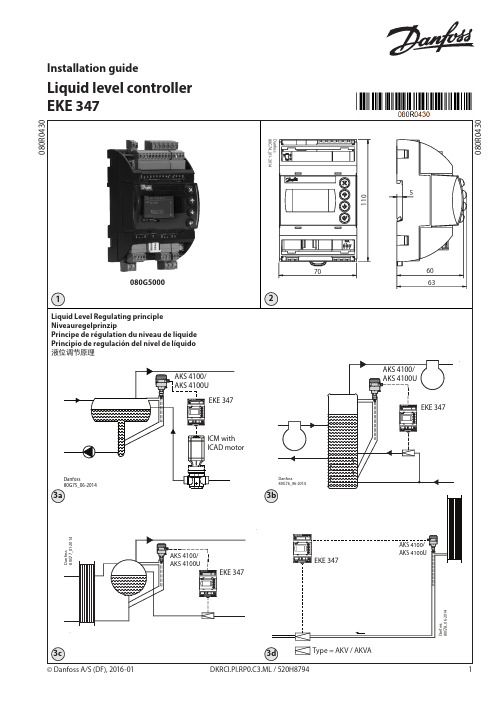
Installation guideLiquid level controller EKE 347© Danfoss A/S (DF), 2016-01DKRCI.PI.RP0.C3.ML / 520H87941yellowblueorangeblue2 DKRCI.PI.RP0.C3.ML / 520H8794 © Danfoss A/S (DF), 2016-01© Danfoss A/S (DF), 2016-01 DKRCI.PI.RP0.C3.ML / 520H8794 34 DKRCI.PI.RP0.C3.ML / 520H8794 © Danfoss A/S (DF), 2016-01Press and holdLog inSlider indicating position withinthe number of submenues© Danfoss A/S (DF), 2016-01 DKRCI.PI.RP0.C3.ML / 520H8794 5ENGLISHLiquid Level Regulating principle Fig. 3a:LOWSystem configuration ICAD Regulating principle LowLevel Signal setup AKS 4100 Fig. 3b:LOWSystem configuration AKV/A Regulating principle LowLevel Signal setup AKS 4100 Fig. 3c:LOWSystem configuration AKV/A Regulating principle LowLevel Signal setup AKS 4100 Fig. 3d:HIGHSystem configuration AKV/A Regulating principle HighLevel Signal setup AKS 4100Necessary connections (fig. 4, 5 and 6) Terminals:28-29 Supply voltage 24 V a.c. or d.c.1-7 Signal from level transmitter type AKS 4100/4100U or7-10 Signal from level transmitter type AKS 4136-37 Expansion valve type AKV or AKVA (see note to the right) or23-24 Expansion valve type: ICM withICAD13-14 Switch function for start/stop of controller. If a switch isnot connected, terminals 13 and 14must be shortcircuited.Application dependent connections(fig. 4, 5 and 6)Terminals:33-35 Relay for common alarm.Installer can choose betweenNormally Open (33-34) or NormallyClosed (34-35) circuits.The relay will switch according tothe programmed setting.25-27 Relay for low level limit.Installer can choose betweenNormally Open (26-27) or NormallyClosed (25-26) circuits.The relay will switch when the setvalue is passed.30-32 Relay for upper level limit.Installer can choose betweenNormally Open (30-31) or NormallyClosed (31-32) circuits.The relay will switch when the setvalue is passed.6-10 ICM valve feedback signal fromICAD 0/4-20 mANote!If AKV(A) is used, the power supplymust cover the AKV(A) coil wattageadditionally (see fig. 5).AKV(A) Coil voltage must be thesame as controller supply voltageAC or DC.MASTER/SLAVE and I/O configuration(fig. 7b and 7c)When more controllers are connected viaCAN bus each end of the bus must be ter-minated with a jumper between 15 and 16.Control Panel (fig. 8)The user interface of the control panel con-sists of a multiline display and 4 individualpush buttons: Enter button, Page upbutton, Page down button and Backbutton.Fig. 8 shows the Home display image,which give the actual overview. This is the1 – 3 times (depending on actual position).Display (fig. 9)The display itself show the state of Liquidlevel, Controller Mode (controller On/Off), Valve opening degree, Lower levelalarm (on = no alarm present) and Upperlevel alarm (off = no alarm present).Additional to the external connected alarmaudio/video sources, a Bell symbol willflash in the upper right corner in case of analarm.To see more details on system perfor-mance and setting of parameters, 2different main menu levels can be reachedby operation of the push buttons.6 DKRCI.PI.RP0.C3.ML / 520H8794 © Danfoss A/S (DF), 2016-01ENGLISHRead onlyhighlight.the text changes to framed text.The Status menu is an open menu acces-sible for all. Therefore only 1 parametercan be changed from here. A selection ofother parameters can be seen from thestatus menu:Status menu ( Open menu )OptionsSetpointLiquid level setpoint0 - 100%To enter Setup and service menu fromHome image:Push and hold .Maneuvering in the Status menu and theSetup and service menu’s are done by useof the 4 push buttons shown in fig. 8.The Setup & service menu is divided into3 access levels, where personnel haveindividual authority.8 DKRCI.PI.RP0.C3.ML / 520H8794© Danfoss A/S (DF), 2016-01(D) = Parameter is hidden if not active in the selected applicationENGLISH© Danfoss A/S (DF), 2016-01 DKRCI.PI.RP0.C3.ML / 520H87949(D) = Parameter is hidden if not active in the selected applicationENGLISHResult:Alarm text showing OFFResult:Low level showing ON, Upper level showing OFFENGLISHDEUTSCH NiveauregelprinzipAbb. 3a:ND-Niveauregelung Systemkonfiguration ICAD Regelprinzip ND Niveausignalkonfiguration AKS 4100 Abb. 3b:ND-Niveauregelung Systemkonfiguration AKV/A Regelprinzip ND Niveausignalkonfiguration AKS 4100 Abb. 3c:ND-Niveauregelung Systemkonfiguration AKV/A Regelprinzip ND Niveausignalkonfiguration AKS 4100 Abb. 3d:HD-Niveauregelung Systemkonfiguration AKV/A Regelprinzip H D Niveausignalkonfiguration AKS 4100Erforderliche Anschlüsse (Abb. 4, 5 und 6) Klemmen:28–29 V ersorgungsspannung 24 V ACoder DC1–7 Signal von Niveausonde des Typs AKS 4100/4100U oder7–10 Signal von Niveausonde des Typs AKS 4136–37 E xpansionsventil vom Typ AKVoder AKVA (siehe Hinweis rechts)oder23–24 E xpansionsventil des Typs: ICM mit ICAD13-14 S chalterfunktion für das Ein- und Abschalten des Reglers. Wenn keinSchalter angeschlossen ist, müssendie Klemmen 13 und 14kurzgeschlossen werden.Anwendungsabhängige Anschlüsse(Abb. 4, 5 und 6)Klemmen:33-35 Relais für Sammelalarm.D er Installateur kann wählenzwischens tromlos geöffneten (33–34) oderstromlos geschlossenen (34–35)Kreisen.D as Relais schaltet entsprechendder programmierten Einstellung um.25-27 Relais für untere Niveaugrenze.Der Installateur kann wählenzwischen stromlos geöffneten(26–27) oder stromlosgeschlossenen (25–26) Kreisen.Das Relais schaltet um, wenn derSollwert überschritten wird.30-32 Relais für obere Niveaugrenze.Der Installateur kann wählenzwischen stromlos geöffneten(30–31) oder stromlosgeschlossenen (31–32) Kreisen.Das Relais schaltet um, wenn derSollwert überschritten wird.6-10 Rückmeldesignal des ICM-Ventilsvom ICAD 0/4–20 mAHinweis!Wenn das AKV(A) verwendet wird,muss die Versorgungsspannungzusätzlich die Wattleistung derAKV(A)-Spule abdecken (s. Abb. 5).Die AKV(A)-Spulenspannung mussder Versorgungsspannung(Wechsel- oder Gleichspannung)des Reglers entsprechen.FÜHRUNGSREGLER-/FOLGEREGLER- undE/A-Konfiguration (Abb. 7b und 7c)Wenn mehrere Regler über CANbusangeschlossen sind, muss jedes Ende derBusleitung mit einer Kurzschlussbrückezwischen 15 und 16 terminiert werden.Bedientableau (Abb. 8)Die Nutzeroberfläche des Bedientableausbesteht aus einem mehrzeiligen Displayund vier einzelnen Drucktasten:Eingabetaste, Taste …Nach oben“, Taste…Nach unten“ und …Zurück“-Taste.Abb. 8 zeigt die Anzeige des Einstiegs-Menüs, das eine aktuelle Übersicht gibt.Dies ist der Ausgangspunkt, um in dieMenüs zu gelangen. Zu dieser Anzeigekehren Sie zurück, indem Sie 1–3 Maldrücken(je nach aktueller Position).Display (Abb. 9)Das Display selbst zeigt den Status vonFlüssigkeitsstand, Betriebsart desReglers (Regler Ein/Aus),Ventilöffnungsgrad, Alarm min. Niveau(ein = kein Alarm vorhanden) und Alarmmax. Niveau (aus = kein Alarmvorhanden).Zusätzlich zu den extern angeschlossenenAudio-/Videoalarmquellen blinkt im Falleines Alarms in der oberen rechten Eckeein Glockensymbol.Für detailliertere Informationen zurSystemleistung und der Einstellung vonParametern können durch Betätigung derDrucktasten zwei verschiedeneHauptmenü-Ebenen erreicht werden.DEUTSCHSchreibgeschützt Markieren drücken. eingerahmtem Text.Das Statusmenü ist ein offenes Menü, dasfür alle zugänglich ist. Deshalb kann vonhier nur ein Parameter geändert werden.Eine Auswahl von anderen Parameternkann vom Statusmenü aus angesehenwerden:Statusmenü (Offenes Menü)OptionenSollwertUm vom Einstiegs-Meü ins Konfigurations-und Servicemenü zu gelangen:gedrückt halten.Die Navigation im Statusmenü und imKonfigurations- und Servicemenü erfolgtüber die vier Drucktasten, die in Abb. 8 zusehen sind.Das Konfigurations- & Servicemenü ist indrei Zugriffsebenen unterteilt, in denenDEUTSCH(Hauptschalter ausschalten um Einstellung zu ändern) (D) = Parameter wird nicht angezeigt, falls in der gewählten Anwendung nicht aktivDEUTSCHErgebnis: Alarmtext OFF Ergebnis: Min. Niveau ON Max.Niveau OFFHauptschalter) (Hauptschalter ausschalten umEinstellung zu ändern)(D) = Parameter wird nicht angezeigt, falls in der gewählten Anwendung nicht aktivDEUTSCHFRANÇAISPrincipe de régulation du niveau de liquideFig. 3a :BASConfiguration système ICAD Principe de régulation Bas Configuration du signalde niveau AKS 4100Fig. 3b :BASConfiguration système AKV/A Principe de régulation Bas Configuration du signalde niveau AKS 4100Fig. 3c :BASConfiguration système AKV/A Principe de régulation Bas Configuration du signalde niveau AKS 4100Fig. 3d :HAUTConfiguration système AKV/A Principe de régulation Haut Configuration du signalde niveau AKS 4100Raccordements nécessaires (fig. 4, 5 et 6) Bornes de raccordement :28-29 Tension d'alimentation 24 V c.a. ou c.c. 1-7 T ype de signal du transmetteur de niveau AKS 4100/4100U ou7-10 T ype de signal du transmetteur de niveau AKS 4136-37 T ype de détendeur AKV ou AKVA (consultez la remarque à droite) ou 23-24 T ype de détendeur : ICM avec ICAD 13-14 F onction de pressostat pour marche/ arrêt du régulateur. Si aucunpressostat n'est raccordé, lesbornes de raccordement 13 et14 doivent être court-circuitées.Raccordements dépendant de l'application(fig. 4, 5 et 6)Bornes de raccordement :33-35 Relais pour alarme commune.L'installateur peut choisir des circuitsN ormalement ouverts (33-34) ouNormalement fermés (34-35).L e relais permutera selon le réglageprogrammé.25-27 Relais pour limite de niveau bas.L'installateur peut choisir descircuits Normalement ouverts(26-27) ou Normalement fermés(25-26).Le relais permutera lorsque lavaleur de consigne est dépassée.30-32 Relais pour limite de niveau hautL'installateur peut choisir des circuitsNormalement ouverts (30-31) ouNormalement fermés (31-32).Le relais permutera lorsque lavaleur de consigne est dépassée.6-10 Signal de retour de la vanne del'ICM à partir de l'ICAD 0/4-20 mARemarque :Si un détendeur AKV(A) est utilisé,l’alimentation électrique doitégalement couvrir la puissanceélectrique (en watts) de la bobineAKV(A) (consultez la fig. 5).La tension de la bobine AKV(A)doit être identique à la tensiond’alimentation c.a ou c.c. durégulateur.Configuration MAÎTRE/ESCLAVE et E/S(fig. 7b et 7c)En cas de raccordement d’autresrégulateurs via des bus CAN, chaqueextrémité du bus doit comporter uncavalier entre 15 et 16.Panneau de commande (fig. 8)L'interface utilisateur du panneau decommande est composée d'un affichageà plusieurs lignes et de quatre boutonsindividuels : bouton Entrée, bouton Pagesupérieure, bouton Page inférieure etbouton Retour.La fig. 8 présente l'image de l'Écrand'accueil, lequel affiche la présentationréelle. Il s'agit du point de départ pouraccéder aux menus. Appuyez 1 à 3 foisÉcran (fig. 9)L'écran présente l'état du Niveau deliquide, du Mode du régulateur(régulateur On/Off), du Degréd'ouverture de la vanne, de l'Alarme deniveau bas (on = aucune alarme réglée) etde l'Alarme de niveau haut (off = aucunealarme réglée).En complément aux sources audio/vidéode l'alarme externe connectée, un symbolede cloche clignotera dans le coin supérieurdroit en cas d'alarme.Pour plus de détails concernant lesperformances du système et le réglage desparamètres, utilisez les boutons pouraccéder à deux niveaux de menusprincipaux.FRANÇAISLecture seule en surbrillance. est encadré.Le menu État est un menu ouvert,accessible à tous. Un seul paramètre peutdonc être modifié dans ce menu. Unesélection d'autres paramètres peut êtreconsultée depuis le menu État :Menu État (menu Ouvrir)OptionsValeur de consigneValeur de consigne du 0 - 100 %Pour accéder au menu Installation etentretien depuis l'Écran d'accueil :Appuyez sur le bouton et maintenez-leenfoncé.Utilisez les 4 boutons présentés sur la fig. 8pour naviguer au sein des menus État etInstallation et entretien.Le menu Installation et entretien estcomposé de trois niveaux d'accès, pourFRANÇAISmodifier le réglage) (D) = Paramètre masqué si non actif pour l'application sélectionnéeFRANÇAISmodifier le réglage) (D) = Paramètre masqué si non actif pour l'application sélectionnéeRésultat:Le texte alarme est sur OFF Résultat:Alarme niveau bas est ON Alarme niveau haut est OFFFRANÇAISESPAÑOLPrincipio de regulación del nivel delíquidoFig. 3a:BAJOConfiguración del sistema ICAD Principio de regulación BajoAjuste de señal de nivel AKS 4100 Fig. 3b:BAJOConfiguración del sistema AKV/A Principio de regulación BajoAjuste de señal de nivel AKS 4100 Fig. 3c:BAJOConfiguración del sistema AKV/A Principio de regulación BajoAjuste de señal de nivel AKS 4100 Fig. 3d:ALTOConfiguración del sistema AKV/A Principio de regulación AltoAjuste de señal de nivel AKS 4100Conexiones necesarias (figs. 4, 5 y 6) Terminales:28-29 T ensión de alimentación (24 V c.a.o c.c.).1-7S eñal procedente del transmisor de nivel tipo AKS 4100/4100U o7-10 s eñal procedente del transmisor de nivel tipo AKS 41.36-37Válvula de expansión tipo AKV/AKVA;(consulte la nota a la derecha),o23-24 válvula de expansión tipo ICM con ICAD.13-14 F unción de conmutación para elencendido/apagado delcontrolador.Si no se conecta un interruptor,deberán cortocircuitarse losterminales 13 y 14.Conexiones dependientes de la aplicación(figs. 4, 5 y 6)Terminales:33-35 Relé de alarma común.E l instalador puede elegir entrelos circuitos normalmente abierto(33-34) y normalmente cerrado(34-35).E l relé conmutará según el ajusteprogramado.25-27 E l instalador puede elegir entrelos circuitos normalmente abierto(26-27) y normalmente cerrado(25-26).E l relé conmutará cuando sesobrepase el valor ajustado.30-32 Relé de límite de nivel alto.El instalador puede elegir entrelos circuitos normalmente abierto(30-31) y normalmente cerrado(31-32).El relé conmutará cuando sesobrepase el valor ajustado.6-10 Señal de realimentación de la válvulaICM, procedente del motor ICAD(0/4-20 mA).Nota:Si opta por una válvula de expansiónAKV(A), la fuente de alimentacióndeberá cubrir también la potenciaconsumida por la bobina correspon-diente (consulte la fig. 5).La tensión de la bobina de la válvulade expansión AKV(A) deberá coincidircon la tensión de alimentación delcontrolador (c.a. o c.c.).Configuración MAESTRO/ESCLAVO y deE/S (figs. 7b y 7c)Si se conectan más controladores a travésde un bus CAN, cada extremo del busdeberá terminarse con un puente entre losterminales 15 y 16.Panel de control (fig. 8)La interfaz de usuario del panel de controlse compone de un display multilínea y 4pulsadores individuales: botón Entrar,botón Arriba, botón Abajo y botón Atrás.La fig. 8 muestra el aspecto de la pantallade inicio, que proporciona informaciónresumida acerca de las condicionesactuales. Dicha pantalla es el punto aveces (según el menú seleccionado).Display (fig. 9)La información representada en el displaypermite determinar el nivel de líquidonivel de líquido, el modo delcontrolador(encendido/apagado), elgrado de apertura de la válvula, laalarma de nivel inferior (encendido =ninguna alarma activa) y la alarma de nivelsuperior (apagado = ninguna alarma activa).Además de las alarmas acústicas/visualesexternas conectadas, un icono con formade campana parpadeará en la esquinasuperior derecha en caso de alarma.Si desea obtener más información acercadel rendimiento del sistema y el ajuste delos parámetros, es posible visualizar 2niveles del menú principal empleando lospulsadores.ESPAÑOLSólo lectura.para marcarlo).cambiará al formato enmarcado.El Menú de estado es un menú abiertoal que puede acceder cualquier usuario.Debido a ello, sólo permite modificar 1parámetro. El Menú de estado ponetambién¤ otros parámetros a disposicióndel usuario:Menú de estado (menú abierto)OpcionesPunto consigna Para acceder al menú Ajuste/serviciodesde la pantalla de inicio:mantenga pulsad .La navegación a través del Menú de estadoy el menú Ajuste/servicio se lleva a caboempleando los 4 pulsadores ilustrados enla fig. 8.El menú Ajuste/servicio se divide en 3 nivelesa los que pueden acceder diferentes tipos deESPAÑOLparámetro)(D) = Parámetro oculto si no está activo en la aplicación seleccionadaESPAÑOLtro)(D) = Parámetro oculto si no está activo en la aplicación seleccionadaResultado:El texto de alarma muestra OFF Resultado:Nivel bajo muestra ON, Nivel alto muestra OFF中文液位调节原理图 3a:低系统配置 ICAD高低端控制选择 低液位信号设置AKS 4100图 3b:低系统配置 AKV/A高低端控制选择低液位信号设置AKS 4100图 3c:低系统配置 AKV/A高低端控制选择低液位信号设置AKS 4100图 3d:高系统配置 AKV/A高低端控制选择高液位信号设置AKS 4100必要连接(图4、5和6)接线端:28-29 电源电压 24 V a.c. 或 d.c.1-7液位变送器型号AKS 4100/4100U 或7-10液位变送器型号 AKS 4136-37 膨胀阀类型 AKV 或 AKVA (参见右边备注)或23-24 膨胀阀类型:ICM 阀门(带 ICAD)13-14 启动/停止控制器的开关功能。
韩荣产品资料-2
韩国韩荣数码温度控制器|光电传感器|旋转编码器|接近传感器|计数器|按钮开关|蜂鸣器|信号灯温度控制器是利用感温液体热胀冷缩及液体不可压缩的原理而实现自动调节。
当控制温度升高时感温液体膨胀产生的推力将热媒关小,以降低输出温度;当控制温度降低时感温液体收缩,在复位装置的作用下将热媒开大,以提高输出温度,从而使被控制的温度达到和保持在所设定的温度范围内。
深圳市凯斯机电应用技术XXX(bbb://aaacase-tradeaaa)作为韩国韩荣系列数码温控器华南区的代理商,可以为您提供各种型号,各种规格,各种用途的数码温度控制器,专用温度控制器,温度控制器,普通温度控制器。
韩国韩荣温控器产品包括:可编程温度.湿度控制器、PID 温度控制器、一般型温度控制器、专用温度控制器、温度指示器、温度控制器的周边机器。
可编程温度.湿度控制器:可编程温度.湿度控制器|可编程温度控制器A:可编程温度.湿度控制器:TH500系列可编程温度、湿度控制器:适用触感面板的彩色LCD画面、300模式(总6000段)、接点输入(D.I)8点,数码输出(D.O)20点、基本搭载通信功能(RS232及RS485/422)。
测定范围:温度:-100.0 ~ 200.0 °C、0.000 ~ 5.000 V ( -100.0 ~ 200.0 °C) 。
湿度:-100.0 ~ 200.0 °C ( 0.0 ~ 100.0 % RH ) 、0.000 ~ 5.000 V ( 0.0 ~ 100.0 % RH ) 。
指示精度:温度( ± 0.1 % of F.S ) 、湿度( ± 1 % of F.S )。
取样周期:温/ 湿度500 ms 。
TH300系列可编程温度、湿度控制器:应用触摸屏的彩色LCD画面、300模式(共6000段) 、接点输入(D.I)4点,数码输出(D.O)12点、通讯功能(RS232及RS485/422) 根据型号选择。
凯克斯设备说明书中文版(仅作参考)
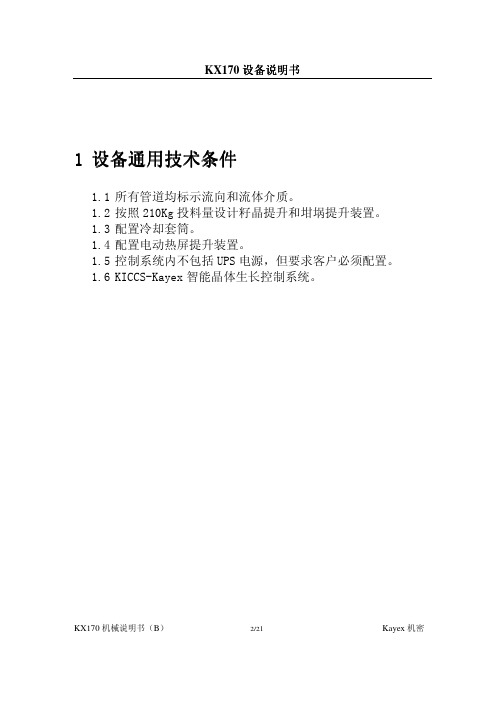
名义直径: 总长度:
3.18 mm (0.125″) 6200mm(244″)
KX170 机械说明书(B)
7/21
Kayex 机密
KX170 设备说明书
2.5 热屏提升
在设备的炉盖上设计有两点式的热屏提升机构。热屏的位置可以通过在 手动模式下的触摸屏来控制,同样也可以通过自动模式下的计算机控 制。自动模式下通过斜率表来控制移动。两个热屏提升口在炉盖上相隔 180 度分布。
极限真空压力: 泄漏率(压力上升速率):
一般 25mtorr(该值是由真空泵和真空系 统决定) 50mtorr/hr
2.6.5. 氧化物控制系统
主真空系统在两个主真空接口的下游处都配置了一个空气注射阀用来 控制氧化物,通过计算机可以同时控制两个阀的开启,每个注射口的流 量稳定在大约或少于 5 升/分钟。
305mm(12″) 2800mm(110″)
KX170 机械说明书(B)
4/21
Kayex 机密
KX170 设备说明书
2.1.7 副室延长室
副室延长室是位于副炉室上部的一个圆筒形腔体。
延长室高度: 延长室内径:
508mm(20″) 191mm(7.5″)
2.1.8 水平调整器
水平调整器是封闭副室延长室上部并用来支撑籽晶提升的装配组件。通 过调整上法兰可以使籽晶旋转轴铅直垂直。水平调整器有两个氩气接入 口,一个熔体温度计接口,一个辅助真空接口。
隔离阀内径:
305mm(12″)
2.1.6 副炉室(接收室)
副炉室是位于隔离阀上的一圆筒形腔体。副炉室上设有便于操作者观察 的观察窗口(1)和籽晶位置监测口(2)。在副炉室上方的水平调整器 设有氩气进气接口(2),熔体测温计(1),一个辅助真空系统抽真空接 口。在副炉室上端还有一个清扫口。
四通道手持式数据记录温度计
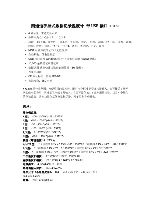
四通道手持式数据记录温度计带USB接口HH147U•4显示区,带背光显示屏•分辨率为0.1°C/0.1°F、1°C/1°F•功能:°C/°F/K、最大值、最小值、平均值、保持、相对、限制、上/下限、类型、计数、时间、时钟、通道、T1-T2、T3-T4、背光、RS232、记录、调用•NIST可溯源校准证书(无数据点)•自动断电、低电量指示•USB接口以及Windows软件(提供可选的RS232电缆)•10,000条数据记录器记录•数据调用-适合快速读取存储器数据(50页/秒)•万年历功能•CE认证标志(符合ITS-90)•电池寿命:550小时HH147U是一款坚固、方便易用的温度计,配有4个标准小型连接器输入。
它可接受7种不同的热电偶类型,同时显示全部4种输入。
它还可提供T3-T4温差测量读数,以及4个输入的单独读数。
其他功能包括低电量指示器、万年历和自动断电。
规格:热电偶范围:K型:-100 ~ 1300°C(-148 ~ 2372°F)J型:-100 ~ 1000°C(-148 ~ 1832°F)E型:-50 ~ 800°C (-58 ~ 1472°F)T型:-100 ~ 400°C (-148 ~ 752°F)R/S型:0 ~ 1700°C (32 ~ 3092°F)N型:-100 ~ 1300°C(-148 ~ 2372°F)精度(环境温度18 ~ 28°C):K/J/E/T型:±(读数的0.1% + 0.7°C)-100 ~ 1300°C ±(读数的0.1% + 1.4°F)-148 ~ 2372°FR/S型:±(读数的0.1% + 2°C)0 ~ 1700°C±(读数的0.1% + 4°F)32 ~ 3092°FN型:±(读数的0.1% + 1.5°C)-100 ~ 1300°C ±(读数的0.1% + 3°F)-148 ~ 2372°F工作温度和湿度:0 ~ 50°C(32 ~ 122°F), 0~80% RH存放温度和湿度:-20 ~ 60°C (-4 ~ 140°F), 0 ~ 80% RH电源要求:4节"AAA"电池(附带)热电偶输入保护:最高4 Vac/Vdc外形尺寸(不包含皮套):164 (高)x 76(宽)x 32 mm(厚)(6.4 x 3 x 1.25")重量:大约270 g (9.5 oz)。
赛米控丹佛斯 分立二极管 SKN 46 数据表
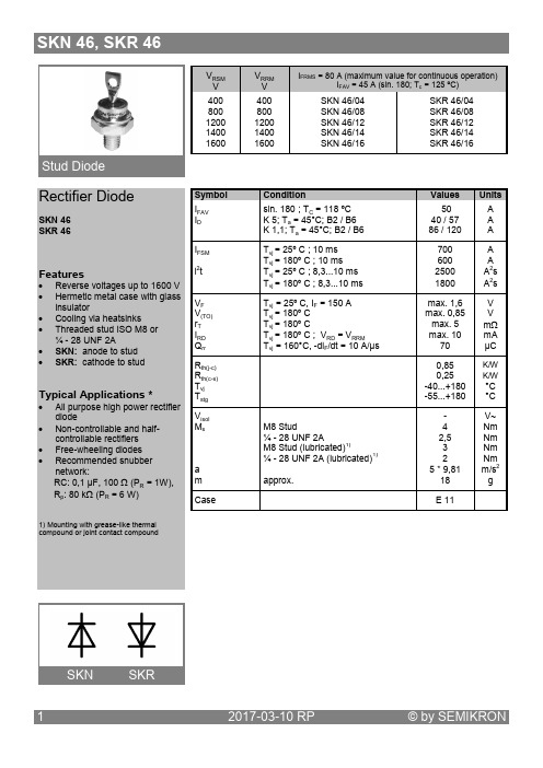
Rectifier DiodeSKN 46 SKR 46Features∙ Reverse voltages up to 1600 V ∙ Hermetic metal case with glass insulator∙ Cooling via heatsinks∙ Threaded stud ISO M8 or ¼ - 28 UNF 2A∙ SKN: anode to stud ∙ SKR: cathode to studTypical Applications *∙All purpose high power rectifier diode∙ Non-controllable and half-controllable rectifiers ∙ Free-wheeling diodes ∙ Recommended snubbernetwork:RC: 0,1 µF, 100 Ω (P R = 1W), R p : 80 k Ω (P R = 6 W) 1) Mounting with grease-like thermal compound or joint contact compoundFig. 1R Power dissipation vs. ambient temperature Fig. 4 Transient thermal impedance vs. timeFig. 6 Surge overload current vs. timeCase E11 (IEC 60191: A 16 U; A 17 MB 2; JEDEC: DO-203 AB)*IMPORTANT INFORMATION AND WARNINGSThe specifications of SEMIKRON products may not be considered as guarantee or assurance of product characteristics ("Beschaffenheitsgarantie"). The specifications of SEMIKRON products describe only the usual characteristics of products to be expected in typical applications, which may still vary depending on the specific application. Therefore, products must be tested for the respective application in advance. Application adjustments may be necessary. The use r of SEMIKRON products is responsible for the safety of their applications embedding SEMIKRON products and must take adequate safety measures to prevent the applications from causing a physical injury, fire or other problem if any of SEMIKRON products become faulty. The user is responsible to make sure that the application design is compliant with all applicable laws, regulations, norms and standards. Except as otherwise explicitly approved by SEMIKRON in a written document signed by authorized representatives of SEMIKRON, SEMIKRON products may not be used in any applications where a failure of the product or any consequences of the use thereof can reasonably be expected to result in personal injury. No representation or warranty is given and no liability is assumed with respect to the accuracy, completeness and/or use of any information herein, including without limitation, warranties of non-infringement of intellectual property rights of any third party. SEMIKRON does not assume any liability arising out of the applications or use of any product; neither does it convey any license under its patent rights, copyrights, trade secrets or other intellectual property rights, nor the rights o f others. SEMIKRON makes no representation or warranty of non-infringement or alleged noninfringement of intellectual property rights of any third party which may arise from applications. Due to technical requirements our products may contain dangerous substances. For information on the types in question please contact the neare st SEMIKRON sales office. This document supersedes and replaces all information previously supplied and may be superseded by updates. SEMIKRON reserves the right to make changes.。
PLC技术规格书
可编程序控制器承包人必须对现场控制站LCS的控制器做详细的配置,列出组成现场控制站控制单元的模块,机架,连接电缆及附件的型号和数量,所选PLC品牌必须为处于国际领先地位的知名品牌。
控制器电源波动适应范围应大于±20%。
鉴于系统防雷性能的要求,输入输出模块均需具备光电隔离性能。
所有输出另加继电器隔离。
由于考虑到控制器输入输出和其他设备需要提供电源,故在控制站配置开关电源,输出电压24VDC。
控制器性能特点:一、CPU指标:●控制器内部采用高性能工业级别微处理器,支持实时的多任务操作系统,处理速度要求每千位指令处理速度不超过0.1毫秒。
●工作存储器不小于128KB,装载存储器不小于2MB。
●控制器必须能够提供包括梯形图、功能图块、结构化文本、顺序功能流程图在内的符合IECll31.3标准的灵活的编程语言支持,数据格式应符合IECll31标准。
●数字量输入/输出地址分别不少于478K,模拟量输入输出地址分别不少于208K。
●控制器支持灵活的网络结构,无需任何编程或者处理器干预,即可实现不同网络之间的通讯桥接和数据交换,支持灵活的网络分段以及相应的隔离式桥接方案,支持EntherNet/IP网络,具有较好的兼容性。
●编程软件采用最新的Windows版,采用结构化、多任务、梯形图、语句表编程方式,具有良好的在线编辑和在线帮助功能。
●控制系统要求完全机架式设计,保证良好的机械物理性能,I/O模块、通讯模块等均应与CPU模块严格保持同等的规格等级和尺寸。
控制器机架应为金属式框架,外部涂敷设计保证良好的机械和防腐性能,机架应为滑轨式设计,控制系统,包括机架,各种插槽式模块都应符合完全的无风扇设计。
●控制单元的处理器必须是经过特殊的涂覆处理,能抗酸性和腐蚀性,能符合工业环境中使用标准。
●具有非易失用户内存。
二、电源模块电源:220VAC+10%。
(与机架和模块相配)。
●工作电压:170-265VAC;●频率范围:47-63HZ;●工作温度:0-60摄氏度;●保存温度:0-85摄氏度;●相对湿度:5-95%;●隔离:2500VDC或1800VAC持续1秒;●掉电延迟:1 3.5ms;三、数字量输入模块●16点或32点输入: 24VDC●电级的故障报告和现场级的诊断检测;●数据时标功能;●完全软件可配置;●故障锁定功能;●开路检测功能;●故障时标功能;●隔离功能;●可拆端子块。
赛米控丹佛斯 SEMITRANS IGBT模块 SKM200GAL17E4 数据表

SEMITRANS ®3IGBT4 ModulesSKM200GAL17E4Features•IGBT4 = 4. generation medium fast trench IGBT (Infineon)•CAL4 = Soft switching 4. Generation CAL-Diode•Insulated copper baseplate using DBC Technology (Direct Copper Bonding) •With integrated Gate resistor•For switching frequenzies up to 8kHz •UL recognized, file no. E63532Typical Applications*•DC/DC – converter •Brake chopper•Switched reluctance motorRemarks•Case temperature limited to T c = 125°C max.•Recommended T op = -40 ... +150°C •Product reliability results valid for T j = 150°CAbsolute Maximum Ratings SymbolConditions Values UnitIGBT V CES T j =25°C 1700V I C T j =175°CT c =25°C 321A T c =80°C248A I Cnom 200A I CRMI CRM = 3xI Cnom 600A V GES -20...20V t psc V CC =1000V V GE ≤ 15V V CES ≤ 1700VT j =150°C10µs T j-40...175°C Inverse diode I F T j =175°CT c =25°C 213A T c =80°C 157A I Fnom200A I FRM I FRM = 2xI Fnom400A I FSM t p =10ms, sin 180°, T j =25°C1170A T j-40 (175)°C Freewheeling diode I F T j =175°CT c =25°C 213A T c =80°C157A I Fnom 200A I FRM I FRM = 2xI Fnom400A I FSM t p =10ms, sin 180°, T j =25°C1170A T j -40...175°C Module I t(RMS)500A T stg -40 (125)°C V isolAC sinus 50 Hz, t =1min4000VCharacteristics SymbolConditions min.typ.max.UnitIGBT V CE(sat)I C =200A V GE =15V chiplevel T j =25°C 1.90 2.20V T j =150°C 2.30 2.60V V CE0chiplevel T j =25°C 0.80.9V T j =150°C 0.70.8V r CE V GE =15V chiplevelT j =25°C 5.50 6.50m ΩT j =150°C8.009.00m ΩV GE(th)V GE =V CE , I C =8mA 5.25.86.4V I CES V GE =0V V CE =1700V T j =25°C 2.7mA T j =150°C mA C ies V CE =25V V GE =0Vf =1MHz 18nF C oes f =1MHz 0.68nF C res f =1MHz0.58nF Q G V GE =- 8 V...+ 15 V 1600nC R GintT j =25°C3.8Ωt d(on)VCC =1200V I C=200AV GE =+15/-15V R G on =2ΩR G off =2Ωdi/dt on =6830A/µs di/dt off =1120A/µs du/dt =5250V/µs T j =150°C 259ns t r T j =150°C 35ns E on T j =150°C 69mJ t d(off)T j =150°C 712ns t f T j =150°C 149ns E offT j =150°C79mJR th(j-c)per IGBT0.122K/W Inverse diodeV F = V EC I F =200AV GE =0V chiplevelT j =25°C 2.00 2.40V T j =150°C 2.15 2.57V V F0chiplevel T j =25°C 1.32 1.56V T j =150°C 1.08 1.22V r FchiplevelT j =25°C 3.4 4.2m ΩT j =150°C 5.4 6.8m ΩI RRM I F =200A di/dt off =5910A/µs V GE =±15VV CC =1200VT j =150°C 272A Q rr T j=150°C63µC E rr T j =150°C 45mJ R th(j-c)per diode0.276K/W Freewheeling diode V F = V EC I F =200AV GE =0V chiplevelT j =25°C 2.00 2.40V T j =150°C 2.15 2.57V V F0chiplevel T j =25°C 1.32 1.56V T j =150°C 1.08 1.22V r F chiplevelT j =25°C 3.4 4.2m ΩT j =150°C5.46.8m ΩI RRM I F =200A di/dt off =5910A/µs V GE =±15VV CC =1200VT j =150°C 272A Q rr T j=150°C63µC E rr T j =150°C 45mJ R th(j-c)per Diode0.276K/W Module L CE 15nH R CC'+EE'terminal-chip T C =25°C 0.55m ΩT C =125°C0.85m ΩR th(c-s)per module 0.020.038K/W M s to heat sink M635Nm M t to terminals M62.55Nm Nm w325gCharacteristics SymbolConditionsmin.typ.max.UnitSEMITRANS ® 3IGBT4 ModulesSKM200GAL17E4Features•IGBT4 = 4. generation medium fast trench IGBT (Infineon)•CAL4 = Soft switching 4. Generation CAL-Diode•Insulated copper baseplate using DBC Technology (Direct Copper Bonding) •With integrated Gate resistor•For switching frequenzies up to 8kHz •UL recognized, file no. E63532Typical Applications*•DC/DC – converter •Brake chopper•Switched reluctance motorRemarks•Case temperature limited to T c = 125°C max.•Recommended T op = -40 ... +150°C •Product reliability results valid for T j = 150°CThis is an electrostatic discharge sensitive device (ESDS), international standard IEC 60747-1, Chapter IX* The specifications of our components may not be considered as an assurance of component characteristics. Components have to be tested for the respective application. Adjustments may be necessary. The use of SEMIKRON products in life support appliances and systems is subject to prior specification and written approval by SEMIKRON. We therefore strongly recommend prior consultation of our staff.。
EKC中文资料
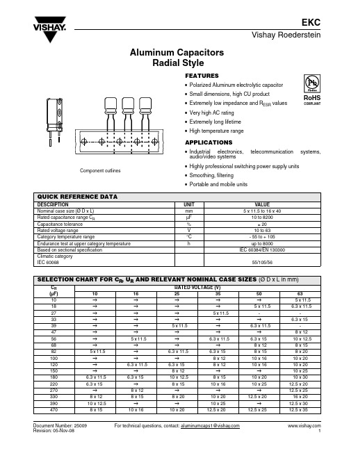
Document Number: 25009For technical questions, contact: aluminumcaps1@Aluminum CapacitorsRadial StyleEKCVishay RoedersteinFEATURES•Polarized Aluminum electrolytic capacitor •Small dimensions, high CU product •Extremely low impedance and R ESR values •Very high AC rating •Extremely long lifetime •High temperature rangeAPPLICATIONS•Industrial electronics, telecommunication systems,audio/video systems•Highly professional switching power supply units •Smoothing, filtering •Portable and mobile unitsComponent outlinesQUICK REFERENCE DATADESCRIPTIONUNIT VALUENominal case size (Ø D x L)mm 5 x 11.5 to 16 x 40Rated capacitance range C R µF 10 to 8200Capacitance tolerance %± 20Rated voltage rangeV 10 to 63Category temperature range°C - 55 to + 105Endurance test at upper category temperature hup to 8000Based on sectional specification IEC 60384/EN 130300Climatic category IEC 6006855/105/56SELECTION CHART FOR C R , U R AND RELEVANT NOMINAL CASE SIZES (Ø D x L in mm)C R (µF)RATED VOLTAGE (V)10162535506310→→→→→5 x 11.5 18→→→→ 5 x 11.5 6.3 x 11.527→→→ 5 x 11.5 --33→→→→→6.3 x 1539→→ 5 x 11.5 → 6.3 x 11.5-47→→→→→8 x 1256→ 5 x 11.5 → 6.3 x 11.5 6.3 x 1510 x 12.568→→→→8 x 128 x 1582 5 x 11.5 → 6.3 x 11.5 6.3 x 158 x 158 x 20100→→→8 x 1210 x 1610 x 20120→ 6.3 x 11.5 6.3 x 158 x 1210 x 1610 x 20150→→8 x 12→→10 x 25180 6.3 x 11.5 6.3 x 1510 x 12.58 x 1510 x 2010 x 30220 6.3 x 15→8 x 1510 x 1610 x 2512.5 x 20270→8 x 12→→→12.5 x 253308 x 128 x 158 x 2010 x 2012.5 x 2016 x 2039010 x 12.5→→10 x 25→12.5 x 304708 x 1510 x 1610 x 2012.5 x 2012.5 x 2512.5 x 35EKCVishay RoedersteinAluminum CapacitorsRadial Style For technical questions, contact: aluminumcaps1@Document Number: 25009GENERAL NOTE•For Standard Packaging Quantity (SPQ) and Minimum Order Quantity (MOQ) please refer to our price list or contact customer service•For other packaging forms please refer to Vishay Roederstein General Information560→→10 x 2512.5 x 2012.5 x 3012.5 x 406808 x 2010 x 20→12.5 x 2512.5 x 3516 x 30820→10 x 2510 x 30→12.5 x 4016 x 35100010 x 20→12.5 x 2516 x 2016 x 3016 x 40120010 x 2510 x 30→12.5 x 3516 x 35-150010 x 3012.5 x 2512.5 x 3012.5 x 4016 x 40-180012.5 x 20→12.5 x 3516 x 30--220012.5 x 2516 x 2012.5 x 4016 x 35--270012.5 x 3012.5 x 3516 x 3016 x 40--330012.5 x 3512.5 x 4016 x 35---390012.5 x 4016 x 3016 x 40---4700→16 x 35----560016 x 3016 x 40----680016 x 35-----820016 x 40-----SELECTION CHART FOR C R , U R AND RELEVANT NOMINAL CASE SIZES (Ø D x L in mm)C R(µF)RATED VOLTAGE (V)101625355063Document Number: 25009For technical questions, contact: aluminumcaps1@EKCAluminum CapacitorsRadial StyleVishay RoedersteinNoteUnless otherwise specified, all electrical values at T a =20 °C, P =80to 120kPa, RH =45to 75 %.ORDERING EXAMPLEEKC 3300 µF/25 V, ± 20 %, size: 16 x 35 mm Leads: LongOrdering code: MALREKC00JU433E00F Leads: ShortOrdering code: MALREKC05...ELECTRICAL DATASYMBOL DESCRIPTIONU R rated voltageC R rated capacitance at 120Hz tan δmax. dissipation factor at 120 Hz Z max. impedance at 100kHzI Rrated alternating current (rms) at 100 kHz and upper category temperatureELECTRICAL DATA AND ORDERING INFORMATIONU R (V)C R 120Hz (µF)NOMINAL CASE SIZE Ø D x L (mm)tan δ120 Hz Z100kHz/20 °C (Ω)I R 100 kHz/105 °C(mA)WEIGHT(g)CATALOG NUMBER (LONG LEADS)1082 5 x 11.5 0.190.751630.50MALREKC00AB282C00F 180 6.3 x 11.50.190.352730.80MALREKC00BB318C00F 220 6.3 x 150.190.25390 1.20MALREKC00BF322C00F 3308 x 120.190.17445 1.00MALREKC00PT333C00F 39010 x 12.50.190.12625 1.90MALREKC00DC339C00F 4708 x 150.190.13555 1.50MALREKC00PF347C00F 6808 x 200.190.095740 2.00MALREKC00PE368C00F 100010 x 200.190.0621040 3.00MALREKC00DE410C00F 120010 x 250.210.0521260 4.00MALREKC00DG412C00F 150010 x 300.210.0441440 4.80MALREKC00DJ415C00F 180012.5 x 200.210.0461340 4.00MALREKC00FE418C00F 220012.5 x 250.230.0341690 4.70MALREKC00FG422C00F 270012.5 x 300.230.0301950 5.40MALREKC00FJ427C00F 330012.5 x 350.250.0242220 5.90MALREKC00FU433C00F 390012.5 x 400.250.0222390 6.40MALREKC00FK439C00F 560016 x 300.290.02523508.80MALREKC00JJ456C00F 680016 x 350.310.022255010.0MALREKC00JU468C00F 820016 x 400.350.018290011.0MALREKC00JK482C00F 1656 5 x 11.5 0.160.751630.50MALREKC00AB256D00F 120 6.3 x 11.50.160.352730.80MALREKC00BB312D00F 180 6.3 x 150.160.253900.80MALREKC00BF318D00F 2708 x 120.160.17445 1.00MALREKC00PT327D00F 3308 x 150.160.13555 1.50MALREKC00PF333D00F 47010 x 160.160.084825 2.40MALREKC00DD347D00F 68010 x 200.160.0621040 3.00MALREKC00DE368D00F 82010 x 250.160.0521260 4.00MALREKC00DG382D00F 120010 x 300.180.0441440 4.80MALREKC00DJ412D00F 150012.5 x 250.180.0341690 4.70MALREKC00FG415D00F 220016 x 200.200.0381630 5.80MALREKC00JE422D00F 270012.5 x 350.200.0242220 5.90MALREKC00FU427D00F 330012.5 x 400.220.0222390 6.40MALREKC00FK433D00F 390016 x 300.220.02523508.80MALREKC00JJ439D00F 470016 x 350.240.022255010.0MALREKC00JU447D00F 560016 x 400.260.018290011.0MALREKC00JK456D00FEKCVishay RoedersteinAluminum CapacitorsRadial Style For technical questions, contact: aluminumcaps1@Document Number: 250092539 5 x 11.5 0.140.751630.50MALREKC00AB239E00F 82 6.3 x 11.50.140.352730.80MALREKC00BB282E00F 120 6.3 x 150.140.25390 1.20MALREKC00BF312E00F 1508 x 120.140.17445 1.00MALREKC00PT315E00F 18010 x 12.50.140.12625 1.90MALREKC00DC318E00F 2208 x 150.140.13555 1.50MALREKC00PF322E00F 3308 x 200.140.095740 2.00MALREKC00PE333E00F 47010 x 200.140.0621040 3.00MALREKC00DE347E00F 56010 x 250.140.0521260 4.00MALREKC00DG356E00F 82010 x 300.140.0441440 4.80MALREKC00DJ382E00F 100012.5 x 250.140.0341690 4.70MALREKC00FG410E00F 150012.5 x 300.160.0301950 5.40MALREKC00FJ415E00F 180012.5 x 350.160.0242220 5.90MALREKC00FU418E00F 220012.5 x 400.180.0222390 6.40MALREKC00FK422E00F 270016 x 300.180.02523508.80MALREKC00JJ427E00F 330016 x 350.200.022255010.0MALREKC00JU433E00F 390016 x 400.200.018290011.0MALREKC00JK439E00F 3527 5 x 11.5 0.120.751630.50MALREKC00AB227F00F 56 6.3 x 11.50.120.352730.80MALREKC00BB256F00F 82 6.3 x 150.120.25390 1.20MALREKC00BF282F00F 1008 x 120.120.17445 1.00MALREKC00PT310F00F 1208 x 120.120.17445 1.00MALREKC00PT312F00F 1808 x 150.120.13555 1.50MALREKC00PF318F00F 22010 x 160.120.084825 2.40MALREKC00DD322F00F 33010 x 200.120.0621040 3.00MALREKC00DE333F00F 39010 x 250.120.0521260 4.00MALREKC00DG339F00F 47012.5 x 200.120.0461340 4.00MALREKC00FE347F00F 56012.5 x 200.120.0461340 4.00MALREKC00FE356F00F 68012.5 x 250.120.0341690 4.70MALREKC00FG368F00F 100016 x 200.120.0381630 5.80MALREKC00JE410F00F 120012.5 x 350.140.0242220 5.90MALREKC00FU412F00F 150012.5 x 400.140.0222390 6.40MALREKC00FK415F00F 180016 x 300.140.02523508.80MALREKC00JJ418F00F 220016 x 350.160.022255010.0MALREKC00JU422F00F 270016 x 400.160.018290011.0MALREKC00JK427F00F 5018 5 x 11.5 0.10 1.201290.50MALREKC00AB218H00F 396.3 x 11.50.100.542190.80MALREKC00BB239H00F 56 6.3 x 150.100.34310 1.20MALREKC00BF256H00F 688 x 120.100.30340 1.00MALREKC00PT268H00F 828 x 150.100.20470 1.50MALREKC00PF282H00F 10010 x 160.100.137552.40MALREKC00DD310H00FELECTRICAL DATA AND ORDERING INFORMATIONU R (V)C R 120Hz (µF)NOMINAL CASE SIZE Ø D x L (mm)tan δ120 Hz Z100kHz/20 °C (Ω)I R 100 kHz/105 °C(mA)WEIGHT(g)CATALOG NUMBER (LONG LEADS)Document Number: 25009For technical questions, contact: aluminumcaps1@EKCAluminum CapacitorsRadial StyleVishay Roederstein12010 x 160.100.13755 2.40MALREKC00DD312H00F 18010 x 200.100.088945 3.00MALREKC00DE318H00F 22010 x 250.100.0731150 4.00MALREKC00DG322H00F 33012.5 x 200.100.0541260 4.00MALREKC00FE333H00F 47012.5 x 250.100.0441490 4.70MALREKC00FG347H00F 5056012.5 x 300.100.0391720 5.40MALREKC00FJ356H00F 68012.5 x 350.100.0331890 5.90MALREKC00FU368H00F 82012.5 x 400.100.0292030 6.40MALREKC00FK382H00F 100016 x 300.100.03021508.80MALREKC00JJ410H00F 120016 x 350.120.027232010.0MALREKC00JU412H00F 150016 x 400.120.024254011.0MALREKC00JK415H00F 6310 5 x 11.5 0.10 1.901030.50MALREKC00AB210J00F 18 6.3 x 11.50.10 1.001610.80MALREKC00BB218J00F 33 6.3 x 150.100.61233 1.20MALREKC00BF233J00F 478 x 120.100.47274 1.00MALREKC00PT247J00F 5610 x 12.50.100.27418 1.90MALREKC00DC256J00F 688 x 150.100.34360 1.50MALREKC00PF268J00F 828 x 200.100.21525 2.00MALREKC00PE282J00F 10010 x 200.100.16650 3.00MALREKC00DE310J00F 12010 x 200.100.16650 3.00MALREKC00DE312J00F 15010 x 250.100.13783 4.00MALREKC00DG315J00F 18010 x 300.100.10960 4.80MALREKC00DJ318J00F 22012.5 x 200.100.11870 4.00MALREKC00FE322J00F 27012.5 x 250.100.0741150 4.70MALREKC00FG327J00F 33016 x 200.100.0851100 5.80MALREKC00JE333J00F 39012.5 x 300.100.0681280 5.40MALREKC00FJ339J00F 47012.5 x 350.100.0631390 5.90MALREKC00FU347J00F 56012.5 x 400.100.0511530 6.40MALREKC00FK356J00F 68016 x 300.100.04617208.80MALREKC00JJ368J00F 82016 x 350.100.040191010.0MALREKC00JU382J00F 100016 x 400.100.036207011.0MALREKC00JK410J00FELECTRICAL DATA AND ORDERING INFORMATIONU R (V)C R 120Hz (µF)NOMINAL CASE SIZE ØD x L (mm)tan δ120 Hz Z100kHz/20 °C (Ω)I R 100 kHz/105 °C(mA)WEIGHT(g)CATALOG NUMBER (LONG LEADS)LOW TEMPERATURE BEHAVIOR (at 120Hz)IMPEDANCE RATIOZ (T2)/Z (T1)RATED VOLTAGE(V)T2/T110 ~ 5063- 55 °C/+ 20 °C36EKCVishay RoedersteinAluminum CapacitorsRadial Style For technical questions, contact: aluminumcaps1@Document Number: 25009ADDITIONAL ELECTRICAL DATAPARAMETER CONDITIONSVALUECurrent Leakage current(T est conditions: U R , 20 °C)After 2 minutes at U RI L2 ≤ 0.01 x C R x U Ror 3 µA(whichever is greater)ResistanceEquivalent series resistance (ESR)Calculated from tan δmax. ESR = tan δ/2 πf C R MULTIPLIER OF RIPPLE CURRENT (I R ) AS A FUNCTION OF FREQUENCYFREQUENCY(Hz)I R MULTIPLIER10 ~ 180 µF220 ~ 560 µF680 ~ 1800 µF2200 ~ 3900 µF4700 ~ 8200 µF1200.400.500.600.750.8510000.750.850.870.900.9510 0000.900.940.950.950.98100 0001.001.001.001.001.00TEST PROCEDURES AND REQUIREMENTSTESTPROCEDURE (QUICK REFERENCE)REQUIREMENTSLoad lifeT amb = 105 °C U R and I R appliedAfter 2000 hours Ø 5, Ø 6.3After 3000 hours Ø 8After 5000 hours Ø 10After 7000 hours Ø 12.5After 8000 hours Ø 16, Ø 18Δ C/C: ± 20 % of initial value I L ≤ spec. limittan δ ≤ 2 x spec. limitShelf lifeNo voltage applied After 1000 hAfter test: U R to be applied for 30 minutes 24 to 48 hours before measurementΔ C/C: ± 20 % of initial value I L ≤ spec.limittan δ ≤ 2 x spec. limitDisclaimer Legal Disclaimer NoticeVishayAll product specifications and data are subject to change without notice.Vishay Intertechnology, Inc., its affiliates, agents, and employees, and all persons acting on its or their behalf (collectively, “Vishay”), disclaim any and all liability for any errors, inaccuracies or incompleteness contained herein or in any other disclosure relating to any product.Vishay disclaims any and all liability arising out of the use or application of any product described herein or of any information provided herein to the maximum extent permitted by law. The product specifications do not expand or otherwise modify Vishay’s terms and conditions of purchase, including but not limited to the warranty expressed therein, which apply to these products.No license, express or implied, by estoppel or otherwise, to any intellectual property rights is granted by this document or by any conduct of Vishay.The products shown herein are not designed for use in medical, life-saving, or life-sustaining applications unless otherwise expressly indicated. Customers using or selling Vishay products not expressly indicated for use in such applications do so entirely at their own risk and agree to fully indemnify Vishay for any damages arising or resulting from such use or sale. Please contact authorized Vishay personnel to obtain written terms and conditions regarding products designed for such applications.Product names and markings noted herein may be trademarks of their respective owners.元器件交易网Document Number: 。
《中国老年学杂志》再次被评为RCCSE中国权威学术期刊(A+)
王雨等基于网络药理学探讨养血培本健脑膏对治疗阿尔茨海默病的作用机制第7期-373-进AD的病理进程。
本研究GO、KEGG富集分析发现,神经递质受体通路、G蛋白耦联胺受体、流体剪切应力与老年性硬化、糖尿病并发症AGE-RAGE通路等可能为养血培本健脑膏治疗AD的机制,而两种富集方法结果的差异可能来源于数据库、算法的不同。
课题组前期研究⑷已证实,养血培本健脑膏可改善模型动物认知功能,抑制海马神经元线粒体凋亡通路及星形胶质细胞活化。
网络药理学方法可较好地预测中药治疗疾病的靶点、通路,提升中药研究的科学性、精准性。
本研究中进一步证实,养血培本健脑膏对治疗AD具有多靶点、多途径和多通路的特点,其治疗机制可能与MAPK3IL-6活性有关,且与其降低海马CA1区神经元A0表达、提高Bcl-2的表达有关。
课题组拟进一步采用实验方法论证本研究挖掘的信号通路,拓展本方的治疗机制。
4参考文献1Cui M,Jiang Y,Zhao Q,et a.Metabodmics and incident UemenPa in older Chinese abults:the Shanahai aging study〔J〕.Alzheimeu De-men),2920;3(3):77961.2LePUuder F,Ehrlich D,Steiner K,et a.The immu/uatyogenesis of Alzheiseks disease is related to the composition of gut microViota 〔〕.Nutrients,2021;2(2):a7H3邵莹,罗占收.中医“治未病”思想与现代医学“预防、诊断和治疗”早期阿尔茨海默病〔〕〕•中国老年学杂志,2519;39(4):991-0.4王文晟,赵云昇,宗星煜,等•养血培本健脑法对AD大鼠认知功能及线粒体凋亡通路影响〔〕〕•时珍国医国药,2518;25(1):1817-75.5GBD2010Dementia Collaboratou.GdUai,revSnai,and national bus-den of Alzheimeks disease and other demenPas:1999-7019 :a systematic analysis for the GdVal Burden of Disease Study2016〔J〕.Lancet Nexal,2019;2(1):C1G97.6Geerts H,Spiros A.aeamina from amyloid tkals in Alzheimeks disease a virtual yakent analysis using a quantiSUve systems phamiacol-op app—ach〔J〕.Alzheisep Dement,2020;3(7):862-72.7Wang X,Sun G,Feng T,tt a.SoVium oligomannate therakenkcallypmoVels gut microViota and suppresses gut bacte/al amino acids-sPaped peuroinUammation to indibit Alzheimer's disease pag—ssSn 〔〕.Cell Rcs,2019;20(19):717605.8Besuard J.Ruda GF,Setola V,et a.Automated design of ligands to polyyPapacolovicai profiSs[J..Nature,2012;292(7223-:22-20.2张学凯,时晶,倪敬年,等•阿尔茨海默病证候级联假说探讨〔〕•中医杂志,2019;90(9):7416.10曾楚华,陈谦峰,黄琼,等•“固本健脑法”防治老年性痴呆理论探源〔〕•中华中医药学刊,2012;54(1):1801G9.1魏江平2弋渊,文跃强,等•从“阳化气,阴成形”理论探讨阿尔茨海默症病机演变规律〔〕•中医杂志,272;57(23):4099-192, 2106012Khan H,Ullak H,Aschner M Jt a.NeuopaSckve effects of quercc-kv in Alzheimer^disease〔J〕.Biomolc cuds,203;3(1-:59.13Zarel M,MoPammabi S,Jakbari S,et a.InWacerebroventWculas ml- c—injectSn of kaempferol on memo—retention of passive avoidapce darning in rats:invodement of ckolinergic mechanism(s-〔J〕.Int J Neurosci,2019;H0(12):1205G2.14Lee JK,Kim NJ.Recent abvances in the indibition of p31MAPK asa uotenkal stmtep for the treatment of Alzheimer^disease〔J〕.Moi-ecylcs,2017;22(1):H87.15Ghasemi R,Moosavl M,Za/fhas A,et a.The intemlay of Akt and ERK in A0toxici/and insu/v-mePiated protection in p/map hippocampal cell culs—〔J〕.J Mol Nenau/202;57(5):32564.16StenUenson J,Nutma E,van des Valk P,tt a.I/lammatSn in CNS neu—Pevenemkve disease[J..Immunodp,203;22(2):204-S9. 17Metaxas A,Anzadne M,Vaitheesua—n R,et al.Neu—i/lammatSn and amydid-hei40are associated with aUuceU serotonin Wansport-ep SERT)activity in a transaeuie moPel of familial Alzheiseks disease[J..Alzheimers Res Ther,2019;2(11):31.18Opsomes R,Contino S,Per/d F,et a.Amyloid precupor protein (APP)controls the expression of the transcripkonal activator neuronal PAS domain protein4(NPAS4-and syyapkc GABA release 〔〕.JNeup7020;7(5):322.12Lin PP,Xie Y,Meng XY,e t a.Histop and progress of hypoiescs and clinical twals for AlzheisePs disease〔J〕.Signal TransPuct Target Thcs,203;2:40.20Li XH,Du LI,Cheua XS,tt a.Glycation exacerdaSs the neuronal toxicity of0-emydid〔J〕.Cell Death Dis,202;4(7):c073.〔20206967修回〕(编辑李男)《中国老年学杂志》再次被评为RCCSE中国权威学术期刊(A+)《中国学术期刊评价研究报告》(第7版)在中国科教评价网正式发布,该版共收录6302种中文学术期刊,65个学科分类,其中临床医学类学术期刊47、种,《中国老年学杂志》再次被评为“RCCSE中国权威学术期刊(A+)”,排名第5位。
4YCC系列单包装可转换气电热炉产品说明书
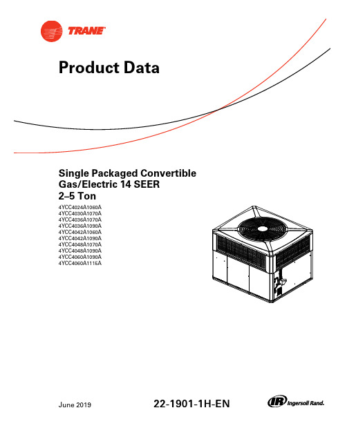
Single Packaged Convertible Gas/Electric14SEER2–5Ton4YCC4024A1060A 4YCC4030A1070A 4YCC4036A1070A 4YCC4036A1090A 4YCC4042A1060A 4YCC4042A1090A 4YCC4048A1070A 4YCC4048A1090A 4YCC4060A1090A4YCC4060A1115AJune201922-1901-1H-E NTable of ContentsSingle Packaged ConvertibleGas/Electric SystemsTrane offers a complete family of packaged gas/electric heating and cooling systems,designed toprovide the unbeatable combination of energy efficiency and lower operating costs.In warmweather,the package gas/electric system functions as an all-electric,high efficiency airconditioner.In cold weather,it operates as a natural gas or propane gas furnace,offering thebest of both energy worlds.B e c a u s e c o o l i n g a n d h e a t i n g f u n c t i o n s a r e a l l c o n t a i n e d i n a s i n g l e c a b i n e t,a s i n g l ep a c k a g e d c o n v e r t i b l e g a s/e l e c t r i c s y s t e m i s e a s y t o i n s t a l l a n d s e r v i c e.It can be flush mounted beside your home at ground level or placed on the roof for horizontal ordownflow installation.When connected to an optional American Standard thermostat control,and air distribution ducts,you have a highly efficient,total home comfort system.S i n g l e P a c k a g e d C o n v e r t i b l e G a s/E l e c t r i c S y s t e m s a r e u n m a t c h e d i n q u a l i t y a n dr e l i a b i l i t y.All major components on these products,including the compressor,have been designed andmanufactured for maximum service.Every compressor is designed and manufactured toexacting specifications.Each design is life tested in extreme environments to ensure reliable andlong lasting operation in normal applications.Each compressor has internal motor protection foradded reliability.S i n g l e P a c k a g e d C o n v e r t i b l e G a s/E l e c t r i c S y s t e m s p r o v i d e b e t t e r p e r f o r m a n c e.Our single packaged cooling/heating units offer cooling/heating efficiencies that are unmatchedin the industry and provide you with a product far superior in performance than the competition.Optional Equipment Listing(a)Must use internal filter frame when economizer or fresh air kit is used.(b)It is the responsibility of the installing dealer to properly size the ductwork for each specific application.(c)Dry bulb control standard with economizer.(d)Downflow only.(e)Must be selected per unit and heater modelProduct Specifications(a)Rated in accordance with AHRI Standard210/240.AHRI standard rating conditions are:80D.B.67W.B.entering air to indoor coil.95D.B.entering air tooutdoor coil.(b)Sound Power values are not adjusted for AHRI270–95tonal corrections.(c)Ratings shown are for elevations up to2000ft.For higher elevations reduce ratings at a rate of4%per1000ft.elevation.(d)Convertible to LPG.(e)This value is approximate.For more precise value,see Unit Nameplate.(f)Standard Air—Dry Coil—Outdoor.(g)Based on ernment Standard Tests.(h)Filters must be installed in return air stream.Square footages listed are based on300f.p.m.face velocity.If permanent filters are used size permanufacturer’s recommendation with a clean resistance of0.05”W.C.(a)Rated in accordance with AHRI Standard210/240.AHRI standard rating conditions are:80D.B.67W.B.entering air to indoor coil.95D.B.entering air tooutdoor coil.(b)Sound Power values are not adjusted for AHRI270–95tonal corrections.(c)Ratings shown are for elevations up to2000ft.For higher elevations reduce ratings at a rate of4%per1000ft.elevation.(d)Convertible to LPG.(e)This value is approximate.For more precise value,see Unit Nameplate.(f)Standard Air—Dry Coil—Outdoor.(g)Based on ernment Standard Tests.(h)Filters must be installed in return air stream.Square footages listed are based on300f.p.m.face velocity.If permanent filters are used size permanufacturer’s recommendation with a clean resistance of0.05”W.C.(a)Rated in accordance with AHRI Standard210/240.AHRI standard rating conditions are:80D.B.67W.B.entering air to indoor coil.95D.B.entering air tooutdoor coil.(b)Sound Power values are not adjusted for AHRI270–95tonal corrections.(c)Ratings shown are for elevations up to2000ft.For higher elevations reduce ratings at a rate of4%per1000ft.elevation.(d)Convertible to LPG.(e)This value is approximate.For more precise value,see Unit Nameplate.(f)Standard Air—Dry Coil—Outdoor.(g)Based on ernment Standard Tests.(h)Filters must be installed in return air stream.Square footages listed are based on300f.p.m.face velocity.If permanent filters are used size permanufacturer’s recommendation with a clean resistance of0.05”W.C.Indoor Fan Performance Table1.Horizontal AirflowTable2.Down AirflowTable3.Horizontal AirflowTable4.Down AirflowTable4.Down Airflow(continued)Table5.Horizontal AirflowTable6.Down AirflowTable6.Down Airflow(continued)Table7.Horizontal AirflowTable7.Horizontal Airflow(continued)Table8.Down AirflowTable9.Horizontal AirflowTable9.Horizontal Airflow(continued)Table10.Down AirflowTable11.Horizontal AirflowTable12.Down AirflowTable12.Down Airflow(continued)Field Wiring DiagramFigure 1.4YCC4—Field Wiring DiagramCONTACTOR/COMPRESSOR/FAN Notes:1. FUSED DISCONNECT SIZE, POWER WIRING AND GROUNDING OF EQUIPMENT MUST COMPLY WITH CODES.2. BE SURE POWER SUPPLY AGREES WITH EQUIPMENT AND HEATER NAMEPLATE.3. LOW VOLTAGE WIRING TO BE 18 AWG MINIMUM CONDUCTOR.4. SEE UNIT DIAGRAM FOR ELECTRICAL CONNECTION DETAILS. ONLY FROM THE THERMOSTAT.6. FOR SINGLE STAGE THERMOSTATS, JUMPER W1 AND W2 TOGETHER. SECOND STAGE HEAT WILL BEGIN 10 MINUTES AFTER FIRST STAGE.DWG. C757192REVAWiring—4YCC4Figure2.4YCC4024–042Figure3.4YCC4024–042。
L-47El HH-22A 双入口J K型热电巧说明书

El HH-22A de entrada dual J/K, se muestra en un tamaño inferior al real. Cada unidad cuenta con 2 termopares tipo K de alambre rebordeado, funda soporte integral, correa para la muñeca, pila de 9V, funda de caucho protectora (HH20-HB), con certificado NIST y manual del operador.La serie HH-20A termómetros manuales pormicroprocesador ofrece un amplio rango de lecturas de temperatura y presenta innovaciones vanguardistas. La pantalla de lectura es LCD de 5 dígitos fácil de leer con indicador de tendencias y autodiagnóstico son estándar. El estuche es impermeable y a prueba de caídas y polvo e incluye una funda soporte/portátil para uso en mesa o mediciones de campo con manos libres.El HH-21A es una unidad de entrada única que aceptatermopares de tipo J, K y T . Desde el panel frontal, el usuario puede seleccionar el tipo de termopar, las unidades de la pantalla ( °C o °F), y la resolución de pantalla (0,1 ° o 1 °). El HH-21A también cuenta con una función de soporte de pantalla. Como con todas las unidades de la serie HH-20A, el HH-21A se caracteriza por la alta precisión, 0,1% de lectura más 1 °F .Los HH-22A y HH-23A aceptan entradas duales. El HH-22A acepta tanto termopares J o K, mientras que el HH-23A funciona con tipos J, K o T . Ambos modelos puedenvisualizar T1 (entrada 1), T2 (entrada 2), T1-T2 (diferencia) o escanear entre T1, T2 y T1-T2. Las funciones estándar para HH-22A y HH-23A incluyen soporte de pantalla, almacenaje máx. y mín. e indicación de tendencias. Las funciones mín. y máx. registran valores mínimos y máximos para T1, T2 y T1-T2. El indicador de tendencia muestra si la entrada visualizada está aumentando, disminuyendo o es estable.U C ada unidad cuenta con un certificado en el que se declara la trazabilidad por NIST (sin puntos)U M odelos de entrada única o dual con soporte de pantalla U L os modelos de entrada dual se caracterizan por una tendencia mín./máx. y distintas mediciones U H H-21A y HH-23A aceptan entradas J, K y TU HH-22A acepta entradas J y K U R esolución 0,1 en °F y °C en todo el rangoU Precisión alta de lectura 0,1% U A utodiagnósticos y retención de la programación del usuario U Conforme con RoHS U Alimentación opcionalPrecisión excepcional Termómetros digitalesModelos de entrada única o dualLa funda (estándar)del HH20-HB proporciona una protección adicional contra choques y clip para cinturón. Funda de recambio(HH20-HB).F u n d a i n c l u i d aSerie HH-20ACuando se enciende un dispositivo HH-20A, éste recuerda lo que estaba haciendo; el tipo de termopar, la resolución y las unidades de temperatura se almacenan en una memoria no volátil de modo que no tenga que volver a programarlo cada vez que lo inicie.Dimensiones: 178 de alto x 74 de anchox 28 mm de profundidad (7,0 x 2,9 x 1,1")Peso: 284 g (10 onzas)Accesorios incluidos: pila alcalina de 9 VCC, sonda de tipo K de alambre rebordeado (para cada entrada), funda de soporte/portátil integrada, correa para la muñeca, funda de caucho, certificado NIST y manual del operador.El HH20CAL, cambia un calibrador de tipo manual a uno portátilpara verificar la calibración en otros instrumentos J, K y T. Haga su pedidoa continuación.EspecificacionesPantalla: LCD de 5 dígitos; indicadorespersonalizados para unidades de termopar tipo °C/°F , soporte y batería baja; el HH-22A y el HH-23A tienen indicadores adicionales para entrada T1, T2, T1-T2,escáner), flechas de tendencia arriba/abajoy datos de almacenamiento mín./máx.Teclado numérico: Cambios momentáneos con respuesta táctil; encendido/apagado,tipo de termopar, unidades, resolución, soporte; el HH-22A y el HH-23A tienen teclas adicionales para almacenaje mín./máx., parar/limpiar almacenaje de tipo deentrada (T1, T2, T1-T2, escáner)Retención de configuración: Lectura seleccionada, tipo de entrada, unidades y resolución retenida en modo apagado Diagnóstico: pila baja, termopar abierto, entrada de teclado inválida, fuera de rango, error interno de hardwarePrecisión: 0,1% rdg + 0,6 °C (1 °F)Repetibilidad: 0,2 °C para1 semana a temperatura constante La caja de distribución de multisonda HH20SW permite hasta 6 sondas.Haga su pedidoa continuación.integrada, correa para la muñeca, pila alcalina de 9V, funda de caucho contra caídas (HH20-HB) y manual del operador.Ejemplo de pedido: HH-22A, termómetro digital con entrada tipo J/K, OMEGACARE SM amplía la garantía estándar de 3 años a un total de 5 años.Funciona con unaConector de salidade 2 posiciones para modelos HH20SWResolución: 0,1 ° a lo largo de toda la gama Coeficiente de temperatura: (0,02% rdg + 0,1 °C) por debajo de 64 °F(18 °C) y por encima de 82 °F (28 °C); incluido en la precisión, entre 18 y 28 °C (64 y 82 °F)Temperatura ambiente:0 a 50 °C (32 a 122 °F), 0 a 90% HR Frecuencia de lectura: 1 por segundoTensión máxima de modo común: Máximo 42 V a toma de tierra Potencia: pila alcalina de 9 Vcc (incluida)Vida útil de la pila: 100 horas, típica, pilaalcalina。
Eaton Moeller PKZM0 电机保护电路切换器说明书
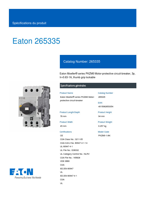
Eaton 265335Eaton Moeller® series PKZM0 Motor-protective circuit-breaker, 3p,Ir=0.63-1A, thumb grip lockableSpécifications généralesEaton Moeller® series PKZM0 Motor-protective circuit-breaker265335401508265335476 mm94 mm45 mm0.257 kgCECSA Class No.: 3211-05CSA-C22.2 No. 60947-4-1-14 UL 60947-4-1UL File No.: E36332UL Category Control No.: NLRV CSA File No.: 165628VDE 0660CSAIEC/EN 60947ULIEC/EN 60947-4-1CSAUL PKZM0-1/AKProduct Name Catalog NumberEANProduct Length/Depth Product Height Product Width Product Weight Certifications Model CodeTurn buttonPhase-failure sensitivity (according to IEC/EN 60947-4-1, VDE 0660 Part 102)Motor protectionPhase failure sensitiveThree-pole ATEX dust-ex-protection, PTB 10, ATEX 3013, Ex II(2) GD100,000 operations (at 400V, AC-3)100,000 Operations (Main conducting paths)Can be snapped on to IEC/EN 60715 top-hat rail with 7.5 or15 mm height.40 Operations/hIII3Motor protective circuit breakerFinger and back-of-hand proof, Protection against direct contact when actuated from front (EN 50274)6000 V AC25 g, Mechanical, according to IEC/EN 60068-2-27, Half-sinusoidal shock 10 msBranch circuit: Manual type E if used with terminal, or suitable for group installations, (UL/CSA)Also motors with efficiency class IE3-5 - 40 °C to IEC/EN 60947, VDE 0660-25 - 55 °C, Operating range≤ 0.25 %/K, residual error for T > 40°Actuator type Features Functions Number of poles Explosion safety category for dust Lifespan, electricalLifespan, mechanicalMounting positionOperating frequencyOvervoltage categoryPollution degreeProduct categoryProtectionRated impulse withstand voltage (Uimp) Shock resistanceSuitable forTemperature compensationAltitude Terminal capacity (flexible with ferrule)Max. 2000 m-25 °C55 °C25 °C40 °C40 °C80 °CDamp heat, cyclic, to IEC 60068-2-30 Damp heat, constant, to IEC 60068-2-781 x (1 - 6) mm², ferrule to DIN 462282 x (1 - 6) mm², ferrule to DIN 462281 x (1 - 6) mm²2 x (1 - 6) mm²18 - 1010 mm1 Nm, Screw terminals, Control circuit cables 1.7 Nm, Screw terminals, Main cable50 Hz60 Hz1 A0.12 kW0.25 kW690 V690 V1 A60 kA DC, up to 250 V DC, Main conducting paths65 kA, 240 V, SCCR (UL/CSA)65 kA, 480 Y/277 V, SCCR (UL/CSA) Screw terminalsAmbient operating temperature - minAmbient operating temperature - maxAmbient operating temperature (enclosed) - min Ambient operating temperature (enclosed) - max Ambient storage temperature - minAmbient storage temperature - maxClimatic proofing Terminal capacity (solid)Terminal capacity (solid/stranded AWG)Stripping length (main cable)Tightening torqueRated frequency - minRated frequency - maxRated operational current (Ie)Rated operational power at AC-3, 220/230 V, 50 Hz Rated operational power at AC-3, 380/400 V, 50 Hz Rated operational voltage (Ue) - minRated operational voltage (Ue) - maxRated uninterrupted current (Iu)Short-circuit currentShort-circuit current rating (type E)ConnectionAccessories required BK25/3-PKZ0-E50 kA, 600 Y/347 V, SCCR (UL/CSA)Basic device fixed 15.5 x Iu, Trip Blocks 15.5 A, Irm, Setting range max.± 20% tolerance, Trip blocks 0.63 A1 AOverload trigger: tripping class 10 A5.33 W0 W1.78 W1 A0 WMeets the product standard's requirements.Meets the product standard's requirements.Meets the product standard's requirements.Meets the product standard's requirements.Meets the product standard's requirements.Does not apply, since the entire switchgear needs to be evaluated.Does not apply, since the entire switchgear needs to be evaluated.Meets the product standard's requirements.eaton-manual-motor-starters-characteristic-characteristic-curve-005.eps eaton-manual-motor-starters-characteristic-characteristic-curve-008.epsDA-DC-00004921.pdfDA-DC-00004892.pdfDA-CE-ETN.PKZM0-1_AKIL122023ZUIL03402034ZIL03407010ZDA-CS-pkzm0_ak_neu_aDA-CD-pkzm0_ak_neu_aeaton-manual-motor-starters-pkz-dimensions.epseaton-manual-motor-starters-pkz-dimensions-002.epseaton-manual-motor-starters-pkzm0-3d-drawing-008.epseaton-manual-motor-starters-pkzm0-3d-drawing.epseaton-manual-motor-starters-transformer-pkzm0-wiring-diagram.epsShort-circuit release Overload release current setting - min Overload release current setting - max Tripping characteristicEquipment heat dissipation, current-dependent PvidHeat dissipation capacity PdissHeat dissipation per pole, current-dependent PvidRated operational current for specified heat dissipation (In) Static heat dissipation, non-current-dependent Pvs10.2.2 Corrosion resistance10.2.3.1 Verification of thermal stability of enclosures10.2.3.2 Verification of resistance of insulating materials to normal heat10.2.3.3 Resist. of insul. mat. to abnormal heat/fire by internal elect. effects10.2.4 Resistance to ultra-violet (UV) radiation10.2.5 Lifting10.2.6 Mechanical impact10.2.7 Inscriptions Characteristic curve Declarations of conformity eCAD modelGuide utilisateur Instructions d'installation mCAD modelSchémasSchémas électriques10.3 Degree of protection of assembliesDoes not apply, since the entire switchgear needs to be evaluated.10.4 Clearances and creepage distancesMeets the product standard's requirements.10.5 Protection against electric shockDoes not apply, since the entire switchgear needs to be evaluated.10.6 Incorporation of switching devices and componentsDoes not apply, since the entire switchgear needs to be evaluated.10.7 Internal electrical circuits and connectionsIs the panel builder's responsibility.10.8 Connections for external conductorsIs the panel builder's responsibility.10.9.2 Power-frequency electric strengthIs the panel builder's responsibility.10.9.3 Impulse withstand voltageIs the panel builder's responsibility.10.9.4 Testing of enclosures made of insulating materialIs the panel builder's responsibility.10.10 Temperature riseThe panel builder is responsible for the temperature rise calculation. Eaton will provide heat dissipation data for the devices.10.11 Short-circuit ratingIs the panel builder's responsibility. The specifications for the switchgear must be observed.10.12 Electromagnetic compatibilityIs the panel builder's responsibility. The specifications for the switchgear must be observed.10.13 Mechanical functionThe device meets the requirements, provided the information in the instruction leaflet (IL) is observed.Eaton Corporation plc Eaton House30 Pembroke Road Dublin 4, Ireland © 2023 Eaton. Tous droits réservés. Eaton is a registered trademark.All other trademarks areproperty of their respectiveowners./socialmedia。
赛米控丹佛斯 SEMIPACK 晶闸管 二极管模块 SKKT 273 数据表

6.865 = 6.6) 6.869 = 6.6)5 6.8 = 6.6(8
6.69 = 6.65 F 56 ''' H 8!6 F 56 ''' H 8)
!(66 = !666 ) K 8) L8, > K 8) L
) D >.98 586
!
"
/
+
.
,
1) 0
Symbol
"1 "03
@
1" 1"+" , " **: 2*
+ =
, +-=
,
E % 1B" B" 1B* B* 2
© by SEMIKRON
5! )(
Units
@ @
1 1 A
C C
=C 1=C C
1 1
<=G <=G <=G <=G ; ;
1J M M = @
SKKT SKKH
1
06-05-2008 GIL
© by SEMIKRON
RECTIFIER,DIODE,THYRISTOR,MODULE
Fig. 1L Power dissipation per thyristor vs. on-state current
科茨克(Kimberly-Clark)Jackson安全G80氮膜手套产品介绍说明书
800-851-7538JACKSON SAFETY* G80 NITRILE* Chemical Resistant GlovesProduct Information94445 7 S) 94446 8 (M) 94447 9 (L) 94448 10 (XL)94449 11 (XXL)Material: Nitrile, cotton flock lined, hand specificDesign: Textured fingertips and palm, 13” length, 15 mil thickness Packaging:5 bags, 12 pairs/bag, 60 pairs per casePhysical Properties1 AQL as defined per ISO 2859-1 for sampling by attributes24 MPa, min.400%, min.ASTM D 412 and D 573Minimum Thickness Middle finger 0.34 13 ASTM D 3767 & D 6319Minimum LengthCuff0.26 10325 mmWidth mm (minimum)102105117129134®/* T rademarks of Kimberly-Clark Worldwide, Inc. or its affiliates.Marques déposées de Kimberly-Clark Worldwide, Inc. ou de ses filiales. © 2010 KCWW.K01371 K2724-09-02 07/10P R O F E S S I O N A L *JACKSON SAFETY* G80 Chemical Selection GuideWhen tested for chemical permeation, productperformance is classified in terms of breakthrough timeMeasured breakthrough time (min) Permeation performance level > 10 1 > 30 2 > 60 3 > 120 4 > 240 5> 4806Analysis has been carried out under laboratory conditions and should only be considered as a guide for use. Chemical performance quoted may not be representative of workplace duration of protection due to the other factors that may affect performance (abrasion, temperature, degradation etc.).This information is not intended to replace a hazard analysis and risk assessment by a safety professional or professional judgment in the selection of Personal Protective Equipment (PPE). It is theresponsibility of the user to assess the type of hazards and risksassociated with exposure and then decide on the appropriate PPE for each circumstance.The data in this guide is correct as at the date of print. The data is subject to change as additional knowledge and experience isgained. To view any supplements or updates please visit®/*Trademarks of Kimberly-Clark Worldwide, Inc. or its affiliates.。
EKC347_中文使用说明
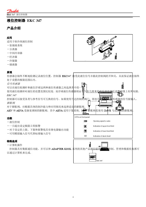
液位控制器EKC 347产品介绍应用适用于制冷剂液位控制-泵储液系统-分离器-中间冷却器-经济器-冷凝器-储液器原理传感器会始终不断地检测记录液位位置,控制器EKC347接受此液位信号并据此控制阀的开和关,从而保证液位始终处于设置的极限范围以内。
信号传感器可以在液位检测杆和液位浮球这两种液位传感器之间选择其中的一种。
使用液位检测杆时液位的设置范围比较宽,而浮球液位传感器则由于只有几厘米的步长而在液位设置范围上有所局限。
EKC 347控制器可以接受各类与参考信号可互换的信号。
如果使用马达控制的阀门,则也可以接受位置传感器的信号做输入。
膨胀阀对于膨胀阀,应根据具体的制冷能力和应用情况来选择适宜的膨胀阀。
AKV和AKV A是脉宽调制的膨胀阀,其中AKV A适用于氨系统。
MEV膨胀阀是使用SMVE马达控制的膨胀阀。
功能-液位控制-一旦超出设定极限立即报警-对于设定的上限,下限和报警线具有继电器输出功能-可用模拟输入信号代替标准输入信号特殊选项-计算机操作控制器具有数据通信功能,并可以和ADAPTER-KOOL系列的其他产品通信联络。
操作控制,管理和数据收集都可以通过计算机来完成。
应用示例泵储液系统调控注液量来保证更加平稳的液位和吸气压力。
满液式蒸发器调制控制和膨胀阀的最大能力可保证稳定的液位-即使在负荷快速变化的情况下也可以。
中间冷却器液位传感器的大量程使得可以控制各种储液容器内的不同液位,并在其最大允许范围内安全地实现各种功能。
冷凝器/储液器控制系统的快速反应使其更适合于充注量少的高压系统。
菜单功能概要语言0=英语;1=德语;2=法语;3=丹麦语;4=西班牙语;5=意大利语;6=瑞典语;改变此设定时必须同时激活o04.o11*06设置电压频率o120/50HZ1/60HZ选择“常规显示”如果o34=0::0:显示的为液位1:显示阀的开度如果o34=1或2:0:显示液位1:显示AKS45的位置信号o1701手工控制输出OFF:无手工控制1: 液位上限继电器开2:液位下限继电器开3:AKV/A 继电器开4:报警继电器激活o18OFF 4接口端子14,15,16的输入信号:0: 关1:4-20mA 2:0-10Vo3102根据需要可设定端子14输入信号的下限值o320V 4.9v 根据需要可设定端子14输入信号的上限值o33 5.0V 10v 接口端子17,18 的输入信号0:端子未使用1:AKS 45的0-20mA.2: AKS45的4-20mA.o342读取液位u01读取液位设定参考值u02读取设定参考值外部校订u06读取设定参考值外部校订u07读取当前模拟输出信号u08读取输入DI状态u10读取阀的开度u24读取液位信号u30读取液位信号u31读取AKS45的信号u32读取AKS45的信号(转换成%)u33服务维护%%mA V mA %mA V mA V操作 显示显示屏数值由3位数字显示,操作完成后,控制器将返回其标准状态并显示测得的液位。
Omega HH309A 四通道类K温度记录仪数据收集器说明书

L-21de interfaz USB y RS232, software Windows, estuche portátil, batería de 9 V , certificado NIST (sin puntos) y manual del operador. Ejemplos de pedidos: : HH309A, termómetro registrador de datos con 4 canales. OCW-3, OMEGACARE SM amplía la garantía estándar de 1 año a un total de 4 años.Especificaciones Rango: -200 a 1.370 °C (-328 a 2.498 °F)Precisión típica: ±0,2% rdg +1 °CResolución: 0,1° entre -200 y 200 °C/F , el resto 1 °C/FFrecuencia de muestreo: 3 segundosCondiciones de funcionamiento: 0 a 50 °C (32 a 122 °F) 0% a 80% HR (0 a 35 °C, 32 a 95 °F) 0% a 60% HR (35 a 50 °C, 95 a 122 °F)Temperatura de almacenamiento: -20 a 60 °C (-4 a 140 °F)Batería: 9 V (incluida)Dimensiones: 184 de largo x 64 de ancho x 30 mm de profundidad (7,25 x 2,5 x 1,2")Peso:Aprox. 250 g (8,8 onzas)U 4 entradas de termopar de tipo KU Muestra 4 canales simultáneamente o 2 canales con DeltaU Registrador de datos con 16.000 registros por canallU Interfaz USB y RS232 con software para Windows ®U Reloj en tiempo realU Apagado automáticoU Función RETENCIÓNU Función MÁX/MÍN U Resolución 0,1 °C/0,1 °FU Indicador de batería bajaU Montaje de trípode incorporadoEl modelo HH309A es un termómetro pequeño de 4 entradas más un registrador de datos potente. Esta unidad puede almacenar hasta 16.000 registros por canal en intervalos programados. El botón REC se utiliza para iniciar y finalizar el registro. Usted puede almacenar tantos conjuntos de datos como desee hasta que la memoria esté llena. La unidad está equipada con un software basado en Windows (Windows 98, NT , XP , ME, Vista) que permite visualizar y almacenar los datos.HH309A puntosEste modelo incluye un termopar tipo K de alambre rebordeado aislado de 1 m (40”) gratuito con conector subminiatura y soporte de carrete para alambre (1 por canal). Solicite N.º de modelo SC-TT-K-30-36.Se incluye termopar Termómetro registrador de datos con cuatro canalesEl modelo HH309A se muestra en un tamaño inferior al real.I n c l u y e c a b l e s d e i n t e r f a z U S B y R S 232。
