HSMH-T500中文资料
沙特维克TH540规格书说明书

Technical Specification Spec number TH540-22 2012-11-16 Sandvik TH540Technical SpecificationSandvik Mining and Construction Reserves the right to change this specification without further notice.APPLICATIONSThe Sandvik TH540 is a high performance 40 tonne articulated underground dump truck for use in 5,0 x 5,0 meter haulage ways. Operator safety, health and comfort are enhanced by the enclosed, vibration isolation, ISO approved cabin. The TH540 is well suited for:• level or steep ramp production haulage in medium to large mines • mine development projects in medium to large mines • tunneling projects with restricted height• 3 pass loading with the Sandvik LH514 loaderCapacitiesPayload capacity 40 000 kg 88 200 lb Dump box22,0 m 3 28,8 yd³ Main dimensionsTotal length10 696mm 421 “ Maximum width 3 065 mm 121 “ Height2 896 mm 114 “ Height of the box2 876 mm113 “Dump Box Motion Times & MovementsDischarging time 14,0 secDumping angle61 º Speeds Forward & Reverse (Level / Loaded)1st gear 5,5 km/h 3,4 mph 2nd gear 7,2 km/h 4,5 mph 3rd gear 9,8 km/h 6,1 mph 4th gear 13,0 km/h 8,1 mph 5th gear 17,2 km/h 10,7 mph 6th gear 22,8 km/h 14,2 mph 7th gear31,1 km/h19,3 mph Reversing with 1st and 3rd gearSandvik Mining and Construction Reserves the right to change this specification without further notice.DIMENSIONS (SIDE VIEW)DIMENSIONS (TOP AND REAR VIEW)POWER TRAINEngineDiesel engine Volvo TAD1640VE (Tier 2) Output 405 kW (543 hp) @ 1 900 rpm Torque 2 761 Nm @ 1 200 rpmNumber of cylinders In-line 6Displacement 16,1 lCooling system Liquid cooledCombustion principle 4-stroke, direct injection, turbocharged, after cooledAir filtration Dry typeElectric system 24 VExhaust system Heat shield for exhaust manifold &turboAverage FuelConsumption49,0 l/h (at 50% load)Fuel Tank Capacity 700 l (185 gal)ConverterDana C9000 series With lock-upTransmissionDana 8000 series Power shift transmission withautomatic electric shift. Sevengears forward and two reverse. AxlesFront axle Kessler D106, oscillation ±13º Rear axle Kessler D106, fixedTiresTire size 29.5R25 E4**Brand and type subject to availabilityVEHICLE WEIGHTSOperating weightsTotal operating weight 34 700 kg76 400 lb Front axle25 900 kg57 000 lb Rear axle 8 800 kg19 400 lb Loaded weightsTotal loaded weight 74 700 kg164 600 lb Front axle 37 200 kg82 000 lb Rear axle 37 500 kg82 700 lb STANDARD OPERATORS COMPARTMENTISO certified ROPS/FOPS cabin with air conditioning Height 2 896 mm114”FRAMERear and front frame Welded steel box construction Central hinge Box constructed, adjustable lowerbearingSTEERING HYDRAULICSFully hydraulic, center articulated, power steering with two double acting cylinders. Closed centre system with a load sensing piston pump and pilot operated orbitral wheel steering.Turning RadiusTurning angle ±42,5 ° Inner 5 015 mm 197 ” Outer 9 132 mm 360 “ Main ComponentsHydraulic pump Variable displacement pistonpumpControl valve Pilot operatedCylinders 125 mm bore X 90 mm rodDUMP BOX HYDRAULICSFull hydraulic system, equipped with variable displacement piston pump. Oil flow to box hydraulic system from the steering hydraulics. Oil flow from the brake circuit pump is divided to the brake system and the oil cooler motor.Main ComponentsHydraulic pump Variable displacement pistonpumpControl valve Solenid operatedCylinders (2) 160 mm bore 110 mm rod Hydraulic oil tankcapacity225 l (60 gal)BRAKESService brakes are spring applied, hydraulically released, liquid cooled (LCB) multi-disc brakes on all wheels with two separate circuits for the front and rear axles. Service brakes also function as an emergency brake, when the emergency brake system is engaged.Main ComponentsPressure accumulator Piston type with chargingvalveBrake valve foot operated pedal, fullymodulatedBrake hydraulic tank 100 l (26,4 gal)Automatic BrakeActivationABASandvik Mining and Construction Reserves the right to change this specification without further notice.Sandvik Mining and Construction Reserves the right to change this specification without further notice. ELECTRICAL EQUIPMENTAlternator 2 x 28 V 140 A, Bosch Batteries 2 x 12V, 160 Ah Starter 24V Lights• Driving 4 x H365W, front & rear • Working 1 pc (H3 65 W) • Parking 4 pcs • Brake 2 pcs • Turn signals 4 pcsInstrumentation5,7 in LCD displaySAFETY AND ERGONOMICSROPS/FOPS certified operators compartment Low frequency suspension seat Adjustable armrests Seat beltLockable main switch Reverse alarm (CEN)External shutdown, 2 pcs in rear ABA brake systemSTANDARD MANUALSInstructions Manual- Operator’s Manual Hard copy, EU-languages - Maintenance Manual Hard copy, EU-languagesParts ManualHard copy, English Service and Repair ManualHard copy, English ToolMan CD (2 pcs)Electronic, in pdf. format, includes all the above manualsOTHER STANDARD EQUIPMENTAuxiliary Engine Brake - Volvo VEB (D16 only) Cyclone pre-filter for A/C device Fire extinguisher, 12 kg (CEN) Flashing beacon Reversing cameraWheel chocks and bracketsOPTIONAL EQUIPMENT Alternative Engines Alternative boxesMaterial density (t/m³) 2,2 2,0 1,7 Volume (m³) 18,0 20,0 24,0 Width(mm) 3 000 3 000 3 150Ejector box 20,0 m³, width 2 980 mmSandvik Mining and Construction Reserves the right to change this specification without further notice.GRADE PERFORMANCEEmptyPercent grade 0 5 10 15 201st gear (km/h) 5,5 5,4 5,4 5,4 5,4 2nd gear (km(h) 7,2 7,2 7,1 7,1 7,0 3rd gear (km/h) 9,8 9,7 9,7 9,6 9,5 4th gear (km/h) 13,0 12,8 12,7 12,5 12,4 5th gear (km/h) 17,2 16,9 16,6 16,4 14,46th gear (km/h) 22,8 22,3 21,8 19,47th gear (km/h) 31,130,126,1LoadedPercent grade0 5 10 15 201st gear (km/h) 5,5 5,4 5,3 5,3 5,2 2nd gear (km(h) 7,2 7,1 7,0 6,9 6,6 3rd gear (km/h) 9,8 9,6 9,4 8,8 5,0 4th gear (km/h) 12,9 12,6 11,8 9,2 5th gear (km/h) 17,1 16,5 12,46th gear (km/h) 22,6 20,37th gear (km/h) 30,6PRODUCTIVITY CURVEVolvo TAD1640VE Tier 2 and TAD1660 Tier 4iCalculated with 2% rolling resistance With lock-upTRACTIVE EFFORT CURVESandvik Mining and Construction Reserves the right to change this specification without further notice.。
英捷思500系列变频器
~2~
500 系列环境 .............................................................................................. 22 3.1.2 安装空间要求 ........................................................................................ 22 3.1.3 机械安装注意事项 ................................................................................. 23 3.2 电气安装 ........................................................................................................ 23 3.2.1 主回路端子说明..................................................................................... 23 3.2.2 变频器主回路接线方式 ........................................................................... 24 3.2.3 主回路配线注意事项 .............................................................................. 24 3.2.4 控制回路端子说明 ................................................................................. 26 3.2.5 端子接线图 ........................................................................................... 28 3.2.6 主控板跳线设置..................................................................................... 30 第四章 键盘操作说明 .................................................................................................. 31 4.1 操作与显示界面介绍 ....................................................................................... 31 4.1.1 功能指示灯说明..................................................................................... 31 4.2 键盘按键说明 ................................................................................................. 32 4.2.1 参数设置 .............................................................................................. 32 4.2.2 电机参数自学习..................................................................................... 33 4.2.3 密码设置 .............................................................................................. 35 第五章 功能参数表 ..................................................................................................... 35 5.1 基本功能参数简表........................................................................................... 35 5.2 监视参数简表 ................................................................................................. 68 第六章 参数说明 ........................................................................................................ 71 P0 组 基本功能组................................................................................................. 71
BMH伺服电机产品手册(中文)斯耐德
3.3 3.3.1 3.3.2 3.3.3 3.3.4
特定电机数据 . . . . . . . . . . . . . . . . . . 20 BMH070 . . . . . . . . . . . . . . . . . . . . 20 BMH100 . . . . . . . . . . . . . . . . . . . . 22 BMH140 . . . . . . . . . . . . . . . . . . . . 24 BMH205 . . . . . . . . . . . . . . . . . . . . 26
可以通过以下电子邮件地址与我们联系: techcomm@。
当必须按照先后顺序执行操作步骤时,您可看见以下表示方法:
执行后续操作步骤的必备条件 ̈ 操作步骤 1 ୵ 对该操作步骤的重要反应 ̈ 操作步骤 2
操作帮助
当针对某一操作步骤的反应有所说明时,您就能够以此来检查该操作步 骤的执行是否正确。
0198441113753, V1.00, 07.2009
并非所有产品在所有国家或地区都有供应。 有关产品的供应状况,请查阅最新的产品目录。 保留如有技术内容修改而不另行通知的权利。 所有说明均为供参考的技术参数,并非所许诺的产品特性。 大多数未带有任何专用商标的产品名称也应视为其各自所有者的商标。
哈兹雷特双钢带铸机保养手册说明书

nance M anualMaMai i n te tenanceI N T RODUCRODUCT T I O N介绍The Hazelett twin-belt continuous casting machine is a precision machine which requires a sensible and consistent maintenance program to prolong its life and achieve desired production goals.It should be entrusted only to persons with good technical ability.哈兹雷特双钢带连续浇铸机是一件精密的设备,它需要一套合理而持续的保养程序来延长设备的使用寿命,从而达到预期的生产目标,应委托给有较高技术水平的人员来管理。
In case of difficulty,you are urged to contact Hazelett before attempting any changes within the machine itself.We particularly counsel against the unadvised changing of anything which would affect the flow of cooling water within the machine or any of the safety devices.如遇困难,在您试图对设备本身进行任何改变前,请联系哈兹雷特公司,我们特别忠告,请不要随意改变设备内部可能影响冷却水流量的部件,或改变任何安全装置。
Hazelett Strip-Casting Corporation哈兹雷特板带铸造公司P.O.Box600柯彻斯特市,佛蒙特州Colchester,VT05446美国05446-0600U.S.A.Telephone:802/863-6376电话:802/863-637Fax:802/863-1523传真:802/863-1523E-mail:*********************E-mail:*********************Contact:Manager of Field Services联系人:现场服务部经理enti i a li lit t y保密性Confi i d entConfWe respectfully advise that the information contained in the data transmitted herein includes confidential and valuable proprietary know-how,technical data and designs of Hazelett Strip-Casting Corporation(Hazelett),which is being entrusted to the recipient.This information shall not be copied or revealed to third parties without the prior written consent of Hazelett,or used for any purpose detrimental to the interest of Hazelett.我们真诚地忠告,此手册所传递的信息包括具有保密性和有价值的专有技术、数据及哈兹雷特板带铸造公司(哈兹雷特),用户须妥善保管,在没有经过哈兹雷特公司书面同意前,不得将其拷贝或告知第三者,或以任何目的为由侵害本公司的利益。
长城润滑油相关参数
5、典型数据 SINOPEC(长城)船用气缸油的典型数据见表1-1所示。
表1-1 SINOPEC(长城)船用气缸油的典型数据
项目
SINOPEC(长城)船用气缸油
牌号
4040 4070 4080 5040 5070 50100
粘度等级 碱值等级 a
40
50
40
70
80
40
70 100
碱值,mgKOH/g 41.6 71.8 82.2 41.3 74.5 103.6
Q/SH PRD 056—2007
3、应用范围 SINOPEC(长城)船用系统油产品适用于低速十字头船用柴油机的曲轴箱润 滑,也可用于燃用普通柴油的中速筒状柴油发动机的润滑。
4、注意事项 船用系统油在使用中要注意避免发生水污染。因为船用系统油中存在清净 分散剂,若有水分进入油中后,添加剂会将水分散在油中,形成油-水乳化液, 降低油膜的承载能力,甚至会使机件损坏。尤其是海水进入系统油中后,还会 使轴瓦等运动部件表面受到腐蚀。因此在使用中要定期检查系统油情况,发现 有异常情况,及时处理解决。
1、性能特点 本系列产品是由石蜡基矿物基础油和精选的高性能添加剂调制而成。本产 品中的4008在山东海丰公司的万吨级集装箱轮“海丰东京”号上通过了近6000 小时的实船试验,获得了MAN公司的认证。本系列产品适用于燃烧不同硫含量燃 料的低速十字头柴油发动机的曲轴箱润滑及机尾轴等辅助设备的润滑。 本系列产品具有优异的分水性能,能迅速将进入油中的水分分离,确保油 品性能稳定;优异的抗氧化性能及热稳定性,降低油品的氧化速度,延长使用 时间;良好的清净分散性,使积炭、油泥等分散成微小颗粒并悬浮在油中,保 持发动机清洁;优良的防锈性能和抗腐蚀性能,防止机件的锈蚀和腐蚀,保护 发动机。 2、技术规格 SINOPEC(长城)船用系统油产品符合以下技术规格要求:
ABB ACS550 一般目的电机驱动器产品系列说明书

Phone: 033 22356676***********************************Low voltage AC drivesABB general purpose drivesACS5500.75 to 355 kW/1 to 500 hpCatalogType designation:Product seriesRating and types Voltages Construction DimensionsOptions ACS550–01–03A3–4+B055Selecting and ordering your driveBuild up your own ordering code using the type codekey below or contact your local ABB drives salesoffice and let them know what you want. Use page 3as a reference section for more information.2 ABB general purpose drives ACS550 | CatalogContentsABB general purpose drives, ACS550Catalog | ABB general purpose drives ACS550 34 ABB general purpose drives ACS550 | CatalogABB general purpose drivesABB general purpose drives are simple to buy, install, configure and use, saving considerable time. They are widely available through ABB channel partners. The drives have common user and process interfaces with fieldbuses, common software tools for sizing, commissioning, maintenance and common spare parts.ApplicationsABB general purpose drives can be used in a wide range of industries. Typical applications include pump, fan and constant torque use, such as conveyors. ABB generalpurpose drives are ideal in those situations where there is a need for simplicity to install, commission and use and where customizing or special product engineering is not required.Introduction to ACS550Highlights−FlashDrop tool−Intuitive use with assistant control panel−Swinging choke for superior harmonic reduction −Vector control−Coated boards for harsh environments−Built-in category C2 EMC filter (1st environment) as standard−Flexible fieldbus system with built-in Modbus and numerous internally mountable fieldbus adapters−UL, cUL, CE, C-Tick and GOST R approved −RoHS compliantFeature Advantage BenefitEnergy efficiency counters Several counters to illustrate saved energy (kWh), carbondioxide emissions (CO 2) and cost in local currency.Shows direct impact on energy bill and helps control operational expenditure (OPEX).Load analyzerLoad analyzer saves process data, such as current and torque values, which can be used to analyze the process and dimensioning of the drive and motor.Optimized dimensioning of the drive, motor and process.FlashDrop tool Faster and easier drive set-up and commissioning.Patented, fast, safe and trouble-free parametrization method without electricity.Assistant control panelTwo soft-keys, function of which changes according to the state of the panel.Built-in help function via dedicated button.Real-time clock, allows timed tracing of faults and setting of parameters to activate at various times of day.Changed parameters -menu.Easy commissioning.Fast set-up.Easier configuration.Rapid fault diagnosis.Quick access to recent parameter missioning assistantsPID controller, real-time clock, serial communications assistant, drive optimizer, startup assistant.Easy set-up of parameters.Maintenance assistant Monitors consumed energy (kWh), running hours or motor rotation.Takes care of preventative maintenance of drive, the motor or run application.Intuitive featuresNoise optimization.Increases switching frequency of drive when drive temperature is reduced.Controlled cooling fan: the drive is cooled only when necessary.Considerable motor noise reduction.Reduces inverter noise and improves energy efficiency.Choke Patented swinging choke - matches the right inductance to the right load, thereby suppressing and reducing harmonics.Reduces total harmonic distortion (THD) emissions up to 25%.Vector control Improved motor control performance.Enables wider range of applications.Built-in EMC filter Category C2 (1st environment) and category C3 (2nd environment) RFI filters as standard.No need for additional external filtering.Brake chopper Built-in up to 11 kW.Reduced cost.ConnectivityBuilt-in Modbus using EIA-485.Simple to install:–Easy connection of cables–Easy connection to external fieldbus systems through multiple I/Os and plug-in optionsReduced cost.Reduced installation time.Secure cable connections.Mounting template Supplied separately with unit.Quick and easy to mark mounting screw holes on installation surface.RoHS compliantACS550 drives comply with EU Directive RoHS 2002/95/CE restricting the use of certaing hazardous substances.Environmentally friendly product.ACS550–01–03A3–4+B055Technical dataACS550–01–03A3–4+B055Low Voltage Directive 2006/95/ECEMC Directive 2004/108/ECQuality assurance system ISO 9001Environmental system ISO 14001UL, cUL, CE, C-Tick and GOST R approvalsRoHS compliantCatalog | ABB general purpose drives ACS550 5Ratings, types, voltages and constructionType designationDrive’s type designation (shown above and in column 7 of thetables on the right side) identifies your drive by construction,current rating and voltage range. Once you have selected thetype designation, the frame size (column 8) can be used todetermine the drives dimensions, shown on the next page.Construction“01” within the type designation (shown above) variesdepending on the drive mounting arrangement, and powerrating.01 = wall-mounted02 = free-standingVoltagesThe ACS550 is available in two voltage ranges:4 = 380 to 480 V2 = 208 to 240 VInsert either “4” or “2”, depending on your chosen voltage,into the type designation shown above.Normal use vs heavy-duty use. For the majority of pump, fan and conveyorapplications, select “Normal use” fi gures. For high overload requirements, select“Heavy-duty use” fi gures. If in doubt contact your local ABB sales offi ce or yourdrives distributor.PNfor kW = Typical motor power in 400 V at normal usePNfor hp = Typical motor power in 460 V at normal usePhdfor kW = Typical motor power in 400 V at heavy-duty usePhdfor hp = Typical motor power in 460 V at heavy-duty useI 2N for A = Continuous rms current. 10% overload is allowed for one minute in ten minutes.I 2hd for A = Continuous rms current. 50% overload is allowed for one minute in tenminutes.3-phase supply voltage 380 to 480 VWall-mounted unitsFree-standing units200300368160250302ACS550-02-368A-4R8250400486200350414ACS550-02-486A-4R8280450526250400477ACS550-02-526A-4R8315500602280450515ACS550-02-602A-4R8355500645315500590ACS550-02-645A-4R83-phase supply voltage 208 to 240 VWall-mounted unitsACS550–01–03A3–4+B0556 ABB general purpose drives ACS550 | CatalogCatalog | ABB general purpose drives ACS550 7DimensionsElectromagnetic compatibilityThe EMC product standard (EN 61800-3 + Amendment A11[2000]) covers the specific EMC requirements stated for drives (tested with motor and cable) within the EU. The new revision of 61800-3 (2004) product standard can be applied from now on, but latest from 1st October 2007. EMC standards such as EN 55011, or EN 61000-6-3/4, apply to industrial and household equipment and systemsincluding drive component inside. Drive units complyingWall-mounted unitsFree-standing unitsWall-mounted drives Free-standing drives EMC according to EN61800-31stenvironment restricted distribution for frame sizes R3, R4 with75 m motor cables and for frame sizes R1, R2, R5, R6 with 100 m motor cables as standard.2ndenvironment unrestricted distribution for frame sizes R1 to R4 with300 m motor cables and for frame sizes R5 to R8 with 100 m motor cables as standard.These cable lengths are for EMC purposes only. Operational cable lengths are available in the output choke selection table on page 11.For longer motor cable lengths, external EMC filters are available onrequest.EMC standards in general1)The dimensions apply to bookshelf mounting. In fl at type mounting the width anddepth change places. n/a = not applicablezH1 = Height with cable connection box H2 = Height without cable connection box W = Width D = Depthwith requirements of EN 61800-3 are always complient with comparable categories in EN 55011 and EN 61000-6-3/4, but not necessarily vice versa. EN 55011 and EN 61000-6-3/4 do not specify cable length nor require a motor to be connected as a load. The emission limits are comparable according to the following table, EMC standards.WH1DH2DWH11) ACS550-01-246A-4 and ACS550-01-290A-4: 979 mm 2)UL Type 12 not available for ACS550-01-290A-43)ACS550-01-290A-4: 1119 mmACS550–01–03A3–4+B0558 ABB general purpose drives ACS550 | CatalogAssistant control panelThe assistant control panel, which is delivered as standard, features a multilingual alphanumeric display for easy drive programming. The control panel has various assistants and a built-in help function to guide the user. It includes a real time clock, which can be used during fault logging and in controlling the drive, such as start/stop. The control panel can be used for copying parameters for back up or fordownloading them to another drive. A large graphical display and soft keys make it extremely easy to navigate.OptionsControl interfacesPanel mounting kitsTo attach the control panel to the outside of a larger enclosure, two panel mounting kits are available. A simple and cost-efficient installation is possible with the ACS/H-CP-EXT kit, while the OPMP-01 kit provides a more user-friendly solution, including a panel platform that enables the panel to be removed in the same way as a drive-mounted panel. The panel mounting kits include all hardware required, including 3 m extension cables and installation instructions.ACS550–01–03A3–4+B055ACS550–01–03A3–4+B0551) Ordering with a separate material code number.2)One slot available for relay or encoder.3)One slot available for fieldbus adapter. Modbus built-in as standard.Available optionsHow to select optionsThe options shown in the table are available within the ACS550 range. Most of them have an associated 4-figure option code, which is shown in the table. It is this code that replaces B055 in the type code above. External options require a separate order line and material or type code number.Basic control panelThe basic control panel features a single line n umeric display. The panel can beused to control the drive, set the parameter values or copy them from one drive to another.Catalog | ABB general purpose drives ACS550 9Plug-in optionsFlashDrop toolRelay output extension option modulecomponents in the system.Encoder feedback option modulePlug-in fieldbus moduleincreasing system reliability.−DeviceNet TM −LonWorks ®−PROFIBUS DP −CANopen ® −ControlNet −Modbus TCP −EtherNet/IP TM −PROFINET IO −PowerLink−EtherCAT ®For type codes see page 8ACS550–01–03A3–4+B05510 ABB general purpose drives ACS550 | CatalogExternal optionsFlashDrop toolFlashDrop is a powerful palm sized tool for fast and easy parameter selecting and setting. It gives the possibility to hide selected parameters to protect the machine. Only the parameters needed in the application are shown. The tool can copy parameters between two drives or between a PC and a drive. All the above can be done without a power connection to the drive. The interface for FlashDrop is available in all wall-mounted units.DrivePMDrivePM (drive parameter manager) is a tool to create, edit and copy parameter sets for the FlashDrop tool. For each parameter/group the user has a possibility to hide it, which means that the drive user does not see the parameter/group at all.DrivePM requirements−Supported operating systems: Windows NT/2000/XP/Vista FlashDrop package includes −FlashDrop tool−DrivePM software (CD-rom)−User’s manual (hardcopy and PDF)−RS232 cable for connection between PC and the FlashDrop tool −Battery chargerDriveWindow LightDriveWindow Light is an easy-to-use startup and maintenance tool for ACS550 drives. It can be used in an offline mode, which enables parameter setting at the office even before going to the actual site. The parameter browser enables viewing, editing and saving of parameters. The parameter comparison feature makes it possible to compare parameter values between the drive and the file. With the parameter subset you can create your own parameter sets. Controlling of the drive is naturally one of the features in DriveWindow Light. With this software tool, you can monitor up to four signals simultaneously. This can be done in both graphical and numerical format. Any signal can be set to stop the monitoring from a predefined level.Startup wizardsStartup wizards make the setting of parameters easy. Simply launch the wizard, select an appropriate assistant eg, for setting analog outputs, and all parameters related to this function are shown together with help pictures.Highlights−Editing, saving and downloading parameters −Graphical and numerical signal monitoring −Drive control −Startup wizardsDriveWindow Light requirements−Supported operating systems: Windows NT/2000/XP/VistaSREA-01 Ethernet adapter SREA-01 Ethernet adapter with remote monitoring access can send process data, data logs and event messagesindependently, without a PLC or a dedicated on-site computer. It has an internal web server forconfiguration and drive access.Catalog | ABB general purpose drives ACS550 11OptionsExternal optionsBrake units and choppersFrame sizes R1 to R2 are delivered with integrated brakechoppers as standard. Other units can use the compact-sized brake units which include brake chopper and resistor. For more information please refer to the ACS-BRK brake units installation and startup guide.HWDBrake units technical dataDimensions1)The last digit of the output choke type defi nes the degree of protection; X stands for 2 = IP22 or 5 = IP54, 0 = IP002)Cable lengths according to 4 kHz switching frequency 3)Maximum switching frequency to be used with du/dt fi lter is 4 kHz Output chokesOutput chokes are used when motor cables above normal length are required.Cable can be roughly 1.5 times standard cable length, see below.Note:An output choke does not improve the EMC performance of the drive. To fulfi l local EMC requirements use suffi cient RFI fi ltering.For more information refer to the ACS550 User’s manual /Technical reference.12 ABB general purpose drives ACS550 | CatalogCooling and fusesCoolingACS550 is fitted with cooling air fans. The cooling air must be free from corrosive materials and not above the maximum ambient temperature of 40 °C (50 °C with derating). For morespecific environmental limits see page 5.Cooling air flow 380 to 480 V unitsCooling air flow 208 to 240 V unitsFuse connectionsStandard fuses can be used with ABB general purpose drives.For input fuse connections see tables below.Free space requirementsRecommended input protection fuses for 380 to 480 V unitsRecommended input protection fuses for 208 to 240 V units*)According to IEC-60269 standardControl connectionsThese connections are shown as examples only. Please refer to the ACS550 User’s manual, chapter Installations, for more detailed information.1 SCR2 AI13 AGND4 +10V5 AI26 AGND7 AO18 AO29 AGND10 +24V11 GND12 DCOM13 DI114 DI215 DI316 DI417 DI518 DI619 RO1C20 RO1A21 RO1B DIP switch analog inputs0 - 20 mAGround the cable screen on the sourcing endramp pair sel.const.speed 1fwd/revstart/stopDI configuration NPN connected (sink)EIA-485Multidrop applicationOther ModbusdeviceSCRBAGNDBAGNDSCRACS550X3ACS550X1ACS550X1DIP switchanaloginputsDI configurationPNP connected(source) withexternalpower supplyDIP switchEIA-485interfaceSignal termination isselected by DIP switchNottermin.22 RO2C23 RO2A24 RO2B25 RO3C26 RO3A27 RO3B28 SCR29 B30 A31 AGND32 SCR25 RO3C26 RO3A27 RO3B22 RO2C23 RO2A24 RO2B19 RO1C20 RO1A21 RO1B10 +24V11 GND12 DCOM13 DI114 DI215 DI316 DI417 DI518 DI61 SCR2 AI13 AGND4 +10V5 AI26 AGND7 AO18 AO29 AGNDconst.speed 1fwd/revstart/stop+ 24V0-10 V0-10 V0-10 V0(4)-20 mAAI1:AI2:NONONONONONOAI1:+ 0V-AI2:R<10 kΩR<10 kΩCatalog | ABB general purpose drives ACS550 1314 ABB general purpose drives ACS550 | CatalogExpertise at every stage of the value chainSecure uptime throughout the drive life cycleWhether you operate in industry, commerce or a utility your aims remain the same: to keep your motor-driven applications running consistently and efficiently. The life cycle services for ABB drives can help you achieve these aims by maximizing the uptime of your process while ensuring the optimum lifetime of ABB drives in a predictable, safe and low-cost manner.ABB follows a four-phase model for the life cycle management of its drives. The life cycle phases are active, classic, limited and obsolete. Within each phase, every drive series has a defined set of services.ABB drive life cycle management modelPrepurchaseOrder and delivery Installationandcommissioning Operation andmaintenance Upgrade and retrofit Replacementand recyclingTraining and learning Technical supportContractsThe life cycle services for ABB drives span the entire value chain, from the moment you make the first enquiry about a drive through to its disposal and recycling. Throughout the value chain, ABB provides training and learning, technical support and contracts. All of this is supported by one of the most extensive global drive sales and service networks.The four-phase drive life cycle management model provides you with a transparent method for managing your investment in drives. In each phase, you clearly see what life cycle services are available, and more importantly, what services are not available. Decisions on upgrading, retrofitting or replacing drives can be made with confidence.The drive, with complete life cycle services, is available for purchase.The drive, with complete life cycle services, is available for plant extensions.Spare parts, maintenance and repair services are available as long as materials can be obtained.ABB cannot guarantee availability of life cycle services for technical reasons or within reasonable cost.Complete life cycle servicesLimited life cycle servicesTo ensure the availability of complete life cycle services, a drive must be in the active or classic phase. A drive can be kept in the active or classic phase by upgrading, retrofitting or replacing.Caution! A drive entering the limited or obsolete phase has limited repair options. This may result in unpredictable process downtime. To avoid this possibility, the drive should be kept in the active or classic phase.Active Classic Limited ObsoleteNotesCatalog | ABB general purpose drives ACS550 153A F E 64792857 R E V P E N 26.3.2014 #17067© Copyright 2014 ABB. All rights reserved. Specifi cations subject to change without notice.Contact Details:Industrial Supply Syndicate54, Ezra Street, Kolkata - 700 001, INDIAPhone: 22350923, 22356676 Fax: +91 33 3022 2923Email:*******************************:。
白山三相57系列步进马达说明书

最新开发的BAISHAN 三相混合式步进电机,采用交流伺服控制原理,三相正弦电流驱动,具有高转矩、低震动、发热小、可靠性能高等优点,运行性能较二相、五相混合式步进电机有了全面的提高,运行效果可与进口电机相媲美。
通用规格(General specifications )步距精度………………±5% 温升……………………80℃ Max 环境温度………………-20℃~+50℃ 绝缘电阻………………100M ΩMin 500VDC 耐压……………………500V AC 1minute径向跳动………………最大0.06mm (450g 负载) 轴向跳动………………最大0.08mm (450g 负载)电气规格(Specifications )型号步距角电机长度 保持转矩额定电流驱动器电源输入 转子惯量 电机重量 适配驱动器Model StepAngle (°)Length L(mm) Holding Torque (N.m) Current (A/Phase)Power supply Rotor inertia (Kg.cm 2)Weight(Kg) Matched drive BSHB36440.50.455.2DC40V5A0.10.5Q3HB64MABSHB366 53.5 0.9 5.6 DC40V5A 0.22 0.75 Q3HB64MABSHB3681.276.4 1.5 5.8 DC40V5A 0.38 1.1 Q3HB64MA外形尺寸(Dimension )型号D(mm)备注BSHB364 6.35 双平台 3×15 BSHB366 6.35 双平台 3×15 BSHB368 6.35 键槽 3×15接线图(Connections )矩频特性曲线图(Frequency-torque characteristics)。
HM中文说明书1
目录第一节系统说明1 引言2 电解液3 电解槽4 电解液子系统(1)KOH泵(2)KOH贮罐(3)换热器(4)KOH过滤器(5)流量开关(6)KOH温度传感器(7)KOH液位计5 给水子系统(1)给水(2)给水水质监测器(3)给水泵(4)给水控制6 气体控制和调节子系统(1)压力变送器(2)产气速率(3)预压(4)备用(5)压力释放(6)背压调节器(7)差压调节器(8)安全阀(9)排空阀(10)冷凝器和捕集器(11)纸型隔膜(12)氮气冲洗7 氢气干燥(1)干燥器(2)干燥器阀8 冷却及冷凝器冷却水子系统(1)温度调节阀(2)冷凝器冷却水及其控制9 系统安全(1)氧中氢监测器(2)电流监测器(3)氢检测器(4)停车报警10 电力和工艺控制子系统(1)DC电源(2)可编程控制器(3)工艺控制及程序(4)干燥器程序11 数据显示和工艺监控(1)触摸屏显示(2)发光二极管监控第二节发生器安装1 系统类别2 发生器安装3 设备连接(1)给水(2)冷却水(3)冷凝器冷却水(4)氢、氧排气阀(5)产品气输送(6)电力(7)氮气吹洗4电源的电连接5 外部报警连接第三节发生器运行1 前言2 初次启动3 启动模式4 运行模式5 备用模式6 常规运行7 压力释放8 停车第四节维护和校验规程1 前言2 电解液(1)电解液混和(2)电解液注入(3)电解液检查(4)电解液排放3 电解槽检查(1)外观检查(2)内部检查(3)再紧固规程4 纸型隔板更换5 渗透渗漏检查6 KOH过滤器更换7 给水过滤器更换8 KOH泵检查9 阀门和调节器维修和校验(1)电磁阀(2)差压调节器(3)背压调节器(4)止回阀和安全阀10 氧中氢监测器维修及校验(1)流量控制器(2)过滤器罐(3)温度传感器11 系统试压12 差压变速器13 KOH流量开关检查14 给水泵起动及冲洗15 给水检测器检查16 干燥器维修(1)孔板维修(2)止回阀维修(3)分子筛更换(4)气体过滤器更换17 温度调节阀检查第五节排除故障指南附录A目录系统组件图1 框架组件图号;A-12 电解槽组件图号;A-23 给水和冷却水组件图号;A-34 气体控制组件图号;A-45 控制箱组件图号;A-56 干燥器组件图号;A-6附录B目录系统图1 HM管道图图号;M141562 HM-C1D2发生器接线图图号;ES-M-009第一节系统说明1 引言HM系统的基本设备配置包括两块,即氢气发生器和电源。
T500控制器规格书.docx
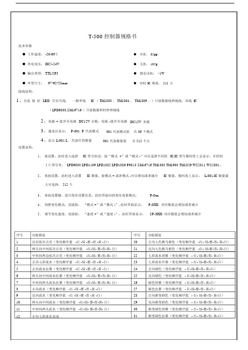
T-500 控制器规格书技术参数●工作温度: -20-60℃● 净重:85gg●供电电压: DC5-24V● 毛重:105g●输出类型: TTL/SPI● 静态功耗:<1W●外型尺寸:97*62*23mm● 控制IC数量:512点接线说明:1、先连接好LED灯信号线,一般单线IC ( TM1803 、 TM1804 、 TM1809 、)只接数据线和地线,双线IC(LPD6803,SM16716 )只接数据和时钟和地线2、电源+接开关电源DC12V正极,电源-接开关电源DC12V负极3、通电后显示:P-001 P代表模式001 代表模式值共 36个模式4、显示L-001 L代表灯的数量001 代表数量值共 512 个点设置说明:1、按设置,此时进入选择IC 型号状态,按“模式 +”或“模式 -”可以选择不同的 IC,IC 型号数码管上会显示,可控制IC型号有: LPD6803 LPD1109 LPD1882 LPD1886 P9813 SM16716 TM1803 TM1903 TM1829 WS2811 WS2801;2、再按设置,此时进入设置IC 数量,按模式 + 或者模式 -可以增加或者减少IC 数量,数码客上显示: L-001,IC 数量最大可选择: 512 个3、再按设置键,进行保存设置信息,此时界面回到变化效果模式:P-0xx4、切换变化模式:直接按:“模式 +”或“模式 -”, 此时界面显示:P-0XX对应数值会增加或者减小5、调节变化速度:直接按:“速度 +”或“速度 -”,此时界面显示:SP-XXX 对应数值会增加或者减少序号功能描述1反向依次点亮(变化顺序蓝 -红 -绿 -紫 -青 -黄 -白)2两头向中间依次点亮(变化顺序蓝 -红-绿- 紫-青-黄- 白)3中间向两边依次点亮(变化顺序蓝 -红-绿- 紫-青-黄- 白)4正向七彩流水(变化顺序蓝 -红 -绿 -紫 -青 -黄 -白)5正向流水拉幕(变化顺序蓝 -红 -绿 -紫 -青 -黄 -白)6两头向中间流水拉幕(变化顺序蓝 -红-绿- 紫-青-黄- 白)7中间向两头流水拉幕(变化顺序蓝 -红-绿- 紫-青-黄- 白)8正向流水(变化顺序蓝 -红 -绿 -紫 -青 -黄 -白)9反向流水(变化顺序蓝 -红 -绿 -紫 -青 -黄 -白)10两头向中间流水(变化顺序蓝 -红-绿- 紫-青-黄- 白)11中间向两头流水(变化顺序蓝 -红-绿- 紫-青-黄- 白)12正向七彩流水追逐序号功能描述20正向七色跑马刷色(变化顺序蓝 -红- 绿-紫-青- 黄-白)21反向七色跑马刷色(变化顺序蓝 -红- 绿-紫-青- 黄-白)22七彩流水闭幕(变化顺序蓝 - 红- 绿-紫-青- 黄-白)23七彩流水开幕(变化顺序蓝 - 红- 绿-紫-青- 黄-白)24正向刷色(变化顺序蓝 - 红-绿-紫-青- 黄-白)25反向刷色(变化顺序蓝 - 红-绿-紫-青- 黄-白)26刷色闭幕(变化顺序蓝 - 红-绿-紫-青- 黄-白)27刷色拉幕(变化顺序蓝 - 红-绿-紫-青- 黄-白)28正向渐变刷色(变化顺序蓝 - 红- 绿-紫-青- 黄-白)29反向渐变刷色(变化顺序蓝 - 红- 绿-紫-青- 黄-白)30渐变刷色闭幕(变化顺序蓝 - 红- 绿-紫-青- 黄-白)31渐变刷色拉幕(变化顺序蓝 - 红- 绿-紫-青- 黄-白)13反向七彩流水追逐32整体七彩渐变14两头向中间七彩流水追逐33整体三基色渐变15中间向两头七彩流水追逐34整体七彩跳变16七色正向跑动拖尾(变化顺序蓝-红 -绿 -紫 -青 -黄 -白)35整体三基色跳变17七色反向跑动拖尾(变化顺序蓝-红 -绿 -紫 -青 -黄 -白)36七色跳变(变化顺序蓝- 红-绿-紫-青- 黄-白)18两头向中间跑动拖尾(变化顺序蓝-红-绿- 紫-青-黄- 白)37三色跳变(变化顺序红- 绿-蓝)19中间到两头跑动拖尾(变化顺序蓝 -红-绿- 紫-青-黄- 白)接线方式:注:先连接好 LED 灯信号线,一般单线 IC(TM1803 、接口说明TM1804 、TM1809 、)只接数据线和地线,双线IC 只接数据和时钟和地线。
润滑油产品介绍解读
金莫顿系列 (合成型车辆用油)
主要销售方向: 4S店、高档换油中心、高级轿车修配厂、高级重型车辆修
配厂、大型工程机械维修站、交运集团、赛事机构、车友
会等。
莫顿系列(标配型车辆用油)
莫顿系列(标配型车辆用油)
莫顿产品种类: 汽机油: SM SL SJ SG SF 柴机油: CI-4 CH-4 CG-4 CF-4 CF CD 液力传动油: MC 6# 8# 液压油: L-HV L-HM 齿轮油: GL-6 GL-5 GL-4 莫顿产品构成: 基础油:PAO合成油 GS 台塑、大连石化等II类或I类 矿物基础油 添加剂:雪佛龙 路博润 雅富顿等国际高端品牌添 加剂
莫顿系列(标配型车辆用油)
莫顿油品配方均采用高清洁低硫低磷技术,属于绿色环保 型产品,符合欧IV 环保排放标准。 适合车型:(普通标准车系)
莫顿汽机油推荐用于:日系、韩系、美系、欧系各类中高
档轿车、越野车、客货等汽油车辆发动机。 莫顿柴机油推荐用于:各类进口或国产中高档重载客货车 辆和国产工程机械柴油车辆发动机。
MD产品优势: 粘度偏大,指数高,粘温性好,油膜附着力极强,压力 强劲稳定,热车压力保持在3~5个压力; 水温变化小,超时间行驶不超过80度,有效降低热能消 耗,使动力明显增强;
MD系列(高碱值增压型车辆用油)
流速快,过油速率及时,冷车启动顺畅;
清洁分散性能极强,有效清洗油泥,分解积碳,延长 发动机的使用寿命。
幅度提高,使用寿命延长,很大程度上满足了长时间不间
莫顿主要产品介绍
“莫顿”产品介绍
莫顿润滑油产品系列 莫顿润滑油产品类型 莫顿润滑油产品组成 莫顿润滑油产品优势
金莫顿系列 (合成型车辆用油)
上海汉霸SP HP 系列

上海汉霸镜面电火花成型机的性能参数型号CNC-双机头火花机床 HP SP 系列 :(SP1-CNC SP2-CNC HP45-CNC HP35-CNC …….)—双机头火花机结构机床,双系统,生产效率提高两倍以上;— 大型双头机火花机同时加工同一模具或分别加工多个模具等多样化的放电方式,可使效率最大化;— 电火花因机头滑枕部分采用高强性的BOX 型结构,加工大重型工件时保持高精密度;— 电火花机床石墨放电加工高效率效果在同行业里,最具优势,同等条件下,效率是其2倍以上;—高效率,高精度,低损耗的优越性能已达到国际同类产品的先进水平优势,是国内高端火花机的首选机床;机床性能特征 1.自适应放电加工控制 2.定时高速抬刀和抬刀高度控制 3.主轴定点控制、放电间隙检测 4.自动油位控制 5.自动防火控制 6.自动报警安全装置 7.防积碳功能 C 系统,触摸屏输入,手控盒操作。
9.工件在机自动测量 10.超精面加工 11.超精边加工 12.X 、Y 、Z 轴进口松下伺服系统。
13.最小电极损耗0.10%14.最佳表面粗糙度Ra0.2um 15.最高生产效率600 mm3/min 16.最小驱动单位1um数控电源装置 1.触摸屏15英寸LCD 液晶显示。
B 数据输入和输出。
3.石墨工艺和镜面硬质合金专用等特殊材料加工回路。
4.低损耗加工回路,AUTO 加工功能单元。
5.防积碳自动检测回路,自动定位功能单元。
6.高速高精度加工系统。
7.自动清弧电路单元。
8.专家工艺数据库系统。
C 指令,标准G 代码,ISO 代码。
10.断电复位,错误信息提示机床型号加工行程X- Y- Z 加工槽尺寸工作台尺寸最大电极/最大工件重量工作台面至电极夹板距离SP1 CNC 300×210×270950×620×360600×40025-400 295-565 SP2 CNC 350×250×270960×620×400 600×40035-400 250-550 HP35 CNC 350×250×300 990×630×420600×40050-550 330-600 HP45 CNC 450×300×300990×640×450600×40080-800 350-620机床型号工作台尺寸加工行程X- Y- Z 加工槽尺寸最大电极/最大工件重量工作台面至电极夹板距离HP55 CNC 800×500 550×400×350 1200×840×540 100-1000 350-700 HE70 CNC 900×500 700×400×300 1400×850×500 50-3000 500-800 HE100 CNC 1200×600 1000×500×400 1800×1100×600 80-4000 500-900 HE130 CNC 1400×700 1300×600×500 2100×1300×650 100-6000 550-1050机床型号工作台尺寸加工行程X- Y- Z 加工槽尺寸最大电极/最大工件重量工作台面至电极夹板距离HE160 CNC1800×9001600×700×5002500×1400×700150-7000 600-1100机床型号工作台尺寸加工行程X- Y- Z 加工槽尺寸最大电极/最大工件重量工作台面至电极夹板距离HE160CNC双头机1800×9001600×700×5002500×1400×700150-7000 600-1100机床型号工作台尺寸加工行程X- Y- Z 加工槽尺寸最大电极/最大工件重量工作台面至电极夹板距离HE200 CNC 2000×10002000×700×5003200×1800×750200-13000 550-1200机床型号工作台尺寸加工行程X- Y- Z 加工槽尺寸最大电极/最大工件重量工作台面至电极夹板距离HP200CNC双头机2000×10002000×700×5003200×1800×750200-13000 550-1200机床型号工作台尺寸加工行程X- Y- Z 加工槽尺寸最大电极/最大工件重量工作台面至电极夹板距离HE250 CNC 2500×12003600×1900×8003600×1900×800200-15000 550-1200机床型号工作台尺寸加工行程X- Y- Z 加工槽尺寸最大电极/最大工件重量工作台面至电极夹板距离HE250CNC双头机2500×12003600×1900×8003600×1900×800200-15000 550-1200机床型号工作台尺寸加工行程X- Y- Z 加工槽尺寸最大电极/最大工件重量工作台面至电极夹板距离HE350 CNC 3500×13503500×800×5004600×2000×850250-20000 850-1350机床型号工作台尺寸加工行程X- Y- Z 加工槽尺寸最大电极/最大工件重量工作台面至电极夹板距离HE350CNC双头机3500×13503500×800×5004600×2000×850250-20000 850-1350。
WW润滑服务的特种润滑脂系列产品列表说明
WW润滑服务
——特种润滑脂系列产品表格说Ww润滑服务是由几个长期从事润滑产品研制、技术服务、产品生产的工程技术人员在四川成都筹建的实体。
我们在解决不同用户设备苛刻润滑的过程中,逐渐形成了我们特色润滑剂产品系列。
WW润滑服务提供的产品包含自制高温、重负荷、长使用寿命特种润滑脂系列产品、其它不同品牌的润滑产品和润滑配件。
WW润滑服务在提供润滑产品与润滑配件的同时,将提供热情周道的售前、售中、售后服务。
根据用户的实际使用工况提供合理的润滑服务。
秉承我们行事方针产品合用好用、服务贴身贴心、价格合情合理。
——
我们真心希望能为广大企业的设备管理带来更多的方便和实惠。
二零一四年一月一日
WW润滑服务特种润滑脂系列产品应用典型部位
1、热处理(烤漆炉、干燥炉、隧道窑、热定型机烘室输送设备的滚动轴承,加热炉、锅炉旋转火嘴轴承等高温重负荷部位);
2、包装、印染行业(单瓦机预热烘缸、滚筒轴承;高温印染机输送链条轴承、压光机滚筒轴承等高温重负荷部位);
3、塑料行业(塑胶挤压机套筒轴承、薄膜拉伸拉幅机、吹袋之旋转模头、注塑机的行位、扣位、顶针、斜顶及边角等易被烧结部位);
4、金属加工行业(火焰切割机车轮轴承、工具机的滚珠导罗杆等高温重负荷部位);
5、高温风机轴承(裂解炉引风机轴承、热熔风机等高温重负荷部位);
6、再生气压缩机的高温轴承。
坦能 T500e 手推式洗地机 操作手册 (中文)说明书

R9015526版本01(10-2019)*9015526*有关最新部件手册及其他语言的操作员手册,请访问:/manualsTennant True ®部件IRIS ®一项Tennant 技术Insta‐Fit ™适配器Smart‐Fill ™自动电瓶注水China2Tennant T500e (10-2019)引言每款新机型均随附本手册。
本手册提供必要的机器操作与维护说明。
在操作或维修机器前,请详读本手册并熟悉机器。
本机器可提供优良的服务。
如能进而做到以下几点,则将能够以最低的成本获得最佳效果:S 操作机器时要小心谨慎。
S 按照提供的维护说明定期维护机器。
S 维修机器时,请使用制造商提供的零件或同类零件。
要查看、打印或下载手册,请在线访问/manuals保护环境请按照当地废物处理法规以环保的方式处理包装材料和使用过的机器组件,如电瓶。
请务必做好回收工作。
Tennant Company PO Box 1452Minneapolis,MN 55440Phone:(800)坦能清洁系统设备(上海)有限公司中国上海青浦漕盈路3777号1幢Tennant Cleaning Systems &Equipment Co.,Ltd Building 1,No.3777Caoying Road Qingpu Shanghai,China 201712电话Phone:862169225333传真Fax:862169225151规格参数和零件如有变更,恕不另行通知。
原稿说明。
Copyright ©2017-2019Tennant Company 版权所有。
保留所有权利。
用途T500e手推式洗地机用于商业用途,如酒店、学校、医院、工厂、商店、办公室和出租业务。
可以擦洗室内环境的硬质表面,例如混凝土、沥青、石头和合成材料等。
该机器不适合用来清洗地毯或砂磨木地板。
仅使用推荐的衬垫/清洗刷以及市场上可买到的地板清洁剂。
HM 系列机器人维护手册说明书

HM系列机器人维护手册维护手册HM系列机器人HM3-0800-0652-0000HM8-0500-0652-0000文档版本V1.0发布日期2022-01-05东莞市李群自动化技术有限公司QKM Technology (Dongguan) Co., Ltd.前言文档版本 V1.0 (2022-01-05) III 前言感谢您购买本公司的机器人本手册记录了机器人维护所需注意事项请参照本手册的内容进行维护操作请妥善保管本手册,以便日后随时取阅概述本手册详细描述了HM 系列机器人的产品特征、主要部件、安装指导、系统调试、技术规格;方便用户能系统地了解和正确使用HM 系列机器人。
读者对象本手册适用于:客户工程师技术支持工程师 应用工程师 安装调试工程师图标含义本文图标将明确说明执行此手册中描述的工作时,可能出现的所有危险、警告、注意和说明;当文档中出现以下图标时请务必留意。
本手册中出现的图标说明如下表所示: 图标说明表示会出现严重的危险情形,如不避免将会造成严重的人员伤害或人员死亡等情况。
表示会出现潜在的危险情形,如不避免会造成人员伤害、机器人毁坏等情况。
表示会出现不可预知的情形,如不避免会导致机器人损坏、性能降低、数据丢失等情况。
表示关键信息阐述、操作技巧提示。
HM 系列机器人维护手册IV 文档版本 V1.0 (2022-01-05)Copyright © 2021李群自动化技术有限公司版权所有,保留所有权利李群自动化技术有限公司(以下简称李群自动化)具有本产品及其软件的专利权、版权和其它知识产权,未经本公司书面授权,任何单位和个人不得擅自摘抄、复制本文档内容;不得直接或间接复制、制造、加工、使用本产品及其相关部分。
商标声明为李群自动化技术有限公司商标,李群自动化拥有此商标的所有权。
免责声明李群自动化不承担由于使用本手册或本产品不当,所造成直接的、间接的、特殊的、附带的或相应产生的损失或责任。
ABB Drives for HVAC ACH550 1到550 HP NEMA UL Type 3

ABB Drives for HVACACH550, 1 to 550 HPNEMA/UL Type 3R Outdoor Rated Enclosed ProductsYour facility is designed towithstand the elements.The outdoor applicationsyou run are rated for therain, cold, heat or shine.Why should your HVACcontrol equipment be anydifferent? Our outdoorrated enclosures willreliably keep inclementweather at bay.A C H 550-P H P F 02U -E N R E V A E N 05/10/2013Environmental and weather protection Designed for peace of mind in operation in sunlight, rain, heat, cold and countless other outdoor environments. The facilities and applications you run need to have access to full output capabilities, no matter the weather outside. Derates due toextremes in temperature, solar exposure, or even worse, failures in the field due to poor environmental protection, are things of the past with the NEMA/UL Type 3R outdoor enclosure.An enclosure for your weatherInhibiting oxidation on the enclosure, in wet environments, is executed through a powder coated steel construction with stainless steel cabinet hardware (locks, hinge pins & rivets) for both wall and free standing mounted enclosures. Ease of use, without opening the enclosure doors for standard operations is accomplished in a couple different ways. A protective external coverallows access to both drive and bypass keypads, while in operation. On smaller wall mount units (below 75 HP , 480V), filter less air intake eliminates the need to change filters.Direct sunlight, full outputIn applications directly exposed tosunlight, dual wall solar shielding offers radiant protection and convectioncooling. Extreme swings in temperature - hot and cold - are mitigated by maintaining the interior cabinet environment through thermostatically controlled cooling fans and silicone element space heaters, with a dedicated control power supply. This allows for full output current at 40o C / 104o F ambient and low temperature climate operation at -18o C / 0o F.Saving system costsReduce site installation costs and minimize costly system downtime, through anintegrated, outdoor-rated design. You can even extend the drive‘s warranty when commissioned by an ABB Certified Start- Up technician.ApplicationsThis package has as many pertinent applications as there are outdoor HVAC needs. However, typical applications include everything from rooftop AHUs, outdoor retrofits, cooling towers, exterior exhaust fans, to outdoor pump skids. And as safety is always a top priority, the packages are UL 508A labeled.Technical data。
长城涡轮机油产品手册 内部资料

(1)长城L- TSA汽轮机油( A级)
采用优质基础油和优选添加剂,具有优异的分水性能 ,防锈防腐性,优良的氧化安定性, D943超过5000小时, 有效延长设备使用寿命。
适用于大功率汽轮机、轻负荷燃气轮机,大中型船舶 及其它工业蒸汽汽轮机、水轮机组的润滑和密封,获得多 个国际OEM认证。
14
(2)长城TSA/LF长寿命涡轮机油
✓ 提高涡轮机油氧化安定性的方法 加入抗氧化添加剂
能改善油品氧化安定性的试剂,称为抗氧化添加剂,简称抗氧 化剂。抗氧化剂可分为酚型、胺型和酚胺型抗氧化剂等。
使用加氢基础油替代传统工艺生产的基础油
传统工艺生产的基础油-I类基础油 物理方法加工:蒸馏、溶剂精制、溶剂脱蜡、白土补充处理 取出理想组分,不改变原组分中固有的烃类结构 加氢基础油- II/III类基础油
化学方法:多环芳烃、胶质和沥青等组分发生开环、裂化、异构化 、脱氧、脱氮等反应, 使其转化为润滑油理想组分。
3 长城涡轮机油的种类和性能 国内汽轮机油标准发展
GB 11120-1989
GB 11120-2011
ISO8068-87 ISO8068-06
长城涡轮机油种类和性能
用途
名称
TSA(B级)汽轮机油
要求改善齿轮承载能力的发电 机、工业驱动装置及其相匹配 的控制系统
续前表
特殊用途 更具体应用
组成和性质
产品 代号
典型应用
气体、直接 或齿轮连接 到载荷
采用一般润 滑系统的单 轴联合循环 机组
一般用途
较高温度下 使用
高承载能力
高温
高温和高承 载力
具有防锈性和氧化安 定性的深度精制石油 润滑油
具有防锈性和改善氧 化安定性的深度精制 石油润滑油
Bosch博世电动工具型号
精心整理Bosch博世电动工具简介:博世电动工具,传承125年的工程技术和创新力量,一直是中国电动工具行业的领跑者。
随着目前大量工程对质量及效率的要求越来越高,除了高端用户以外,广大中端用户——包括手工业者、中小企业、农民工用户,对电动工具的要求也越来越高。
博世T系列在此背景下应运而生。
博世T系列是一个兼顾产品质量与价格的全新系列,T系列延续了博世产品始终卓越的优良传统,保博世电稿因其极长的使用寿命、一流的品质和令人震撼的功率而能满足高作业要求。
博世电稿可以轻松对混凝土、石材、金属、木材和钢材进行钻孔。
带五坑夹头系统的博世电镐是工地上使用的得力工具:坚固且使用舒适。
例如,采用SDS技术的电稿因工具更换方便而表现不凡。
博世电镐因其高材料切除率而表现非凡。
振动控制使其具有较长的运行时间和较高的舒适性。
总有一款博世电稿适合您,即使是重载拆除作业。
Bosch博世充电工具采用博世锂电技术的充电式工具在功率与可靠性方面都树立了全新标杆。
超长的电池使用时间、最轻的重量、极高的耐用性成为这些电动工具的突出特点。
博世也是第一家提供采用锂电技术、覆盖各个电压级别的全系列产品制造商。
博世充电式起子机-比同级产品更紧凑的锂电充电式起子机。
是狭窄空间作业的理想选择。
精巧机型,功率充足,适用于大部分起子应用作业。
重量轻,可降低作业疲劳程度。
安装作业的首选,尤其适用于狭小空间和头顶位置的安装作业。
小尺寸,大功率。
采用锂电技术的14.4伏和18伏基本机型充电式电钻/起子机不仅设计紧凑,而且性能卓越、速度高、使用时间长。
发展成为博世电动工具(中国)有限公司(BOSCH Power Tools)优秀经销商团队(BSS)中的翘楚,年销售额均名列前茅。
公司主营进口、国产专业电动工具、气动工具、五金手动工具、机电设备等业务,资源丰富,业务娴熟,为国内知名电动工具、机电设备供应商。
Bosch博世电动工具型号:博世电动工具的产品型号中字母有不同的含义,了解字母含义有助您选购适合机器。
斯特拉斯克 5 軸工具研磨機 410 型 420 型 430 型 使用說明書说明书
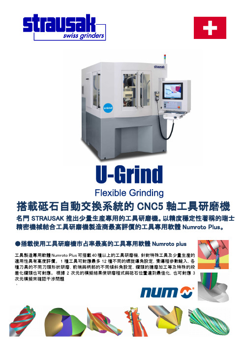
搭載砥石自動交換系統的CNC5軸工具研磨機●搭載使用工具研磨機市占率最高的工具專用軟體Numroto plus名門STRAUSAK 推出少量生産專用的工具研磨機。
以精度穩定性著稱的瑞士精密機械結合工具研磨機製造商最高評價的工具專用軟體Numroto Plus。
工具製造專用軟體Numroto Plus 可搭載40種以上的工具研磨機,針對特殊工具及少量生産的適用性具有高度評價。
1種工具可對應最多12種不同的螺旋導角設定,變導程參數輸入,各種刀具的不同刀頭形狀研磨,前端與柄部的不同傾斜角設定,鑽頭的搪磨加工等及特殊的段差化鑽頭也可對應。
根據2次元的模擬結果使研磨程式與砥石位置達到最佳化,也可對應3次元模擬來確認干涉問題。
微科帝貿易股份有限公司SINCE 1924●最多可搭載6種砥石接頭,進行自動更換 砥石轉接頭採用再現性優,針對研磨時的直徑方向具有高剛性二面拘束的HSK63F。
可對應銑刀、鑽頭﹑鉸刀等的不同工具的全自動連續生產。
可有効規劃砥石排列以減輕砥石干涉對作業者産生的負擔。
●追求精度的工具固定系統 將Collet 的震動誤差的中間値控制靠近在回轉軸的中間處,震動精度可控制在2~3μm 以内,並搭載固定工具用的V Guide。
http://www.ykt.co.jp e-mail:*************.jp〒10569台北市松山區南京東路5段343號6樓之3TEL:02-2745-5430 FAX:02-2745-5630 台中事務所: 台中市台灣大道二段910號5樓-7 ●不需砥石機外量測機,使用機內量測縮短程序時間 一般的刀具研磨機的砥石會用機外量測機台做測量,量測完後的砥石再安裝到機台上,在機台上做測試研磨→測量刀具→砥石研磨點的補正→再加工→測量刀具。
用機外量測機量出來的砥石量測數據用在刀具研磨機台上的話常常會產生誤差情形,從少量生產的觀點來看是沒有效率的作業。
U-Grind 是砥石的直徑,寬度,砥石間的距離,僅花一分鐘的時間便可在機內量測完畢,大幅縮短程序上的時間。
- 1、下载文档前请自行甄别文档内容的完整性,平台不提供额外的编辑、内容补充、找答案等附加服务。
- 2、"仅部分预览"的文档,不可在线预览部分如存在完整性等问题,可反馈申请退款(可完整预览的文档不适用该条件!)。
- 3、如文档侵犯您的权益,请联系客服反馈,我们会尽快为您处理(人工客服工作时间:9:00-18:30)。
1-204HSMD-TX00HSME-TX00HSMG-TX00HSMH-TX00HSMS-TX00HSMY-TX00Device Selection GuideDH AS HighHigh AlGaAs EfficiencyPerformanceEmerald Red Red Orange Yellow Green Green HSMH-HSMS-HSMD-HSMY-HSMG-HSME-Description T400T400T400T400T400T40012 mm Tape, 7" Reel,2000 Devices T500T500T500T500T500T50012 mm Tape, 13" Reel,8000 Devices T600T600T600T600T600T6008 mm Tape, 7" Reel,2000 Devices T700T700T700T700T700T7008 mm Tape, 13" Reel,8000 DevicesSurface Mount LED Indicator Technical DataFeatures• Compatible with Automatic Placement Equipment • Compatible with Infrared and Vapor Phase Reflow Solder Processes• Packaged in 12mm or 8mm tape on 7" or 13" Diameter Reels• EIA Standard Package • Low Package Profile • Nondiffused PackageExcellent for Backlighting and Coupling to Light PipesDescriptionThese solid state surface mount indicators are designed with a flat top and sides to be easily handled by automatic placementequipment. A glue pad is provided for adhesive mounting processes.They are compatible withconvective IR and vapor phase reflow soldering and conductive epoxy attachment processes.The package size and configura-tion conform to the EIA-535BAAC standard specification for case size 3528 tantalum capacitors. The folded leadsH5964-9359Epermit dense placement and provide an external solder joint for ease of inspection.These devices are nondiffused,providing high intensity forapplications such as backlighting,light pipe illumination, and front panel indication.1-205Package DimensionsTape and Reel SpecificationsHewlett Packard surface mount LEDs are packaged tape and reel in accordance with EIA-481A,Taping of Surface MountComponents for Automatic Placement . This packaging system is compatible with tape-fed automatic pick and place systems. Each reel is sealed in avapor barrier bag for added protection. Bulk packaging in vapor barrier bags is availableupon special request.Absolute Maximum Ratings at T A = 25°CDH AS High HighAlGaAs Efficiency Perf.Emerald Parameter Red Red Orange Yellow Green Green Units DC Forward303030303030mA Current[1]Peak Forward3009090609090mA Current[2]Average202525202525mA ForwardCurrent[2]LED Junction95°C TemperatureTransientForwardCurrent[3](10 µs Pulse)500mA Reverse Voltage5V (I R = 100 mA)Operating-40 to +85-20 to +85°C TemperatureRangeStorage-40 to +85°C TemperatureRangeReflow SolderingTemperatureConvective IR235°C Peak, above 185°C for 90 seconds.Vapor Phase 215°C for 3 minutes.Notes:1. Derate dc current linearly from 50°C: For AlGaAs red, high efficiency red, and green devices at 0.67 mA/°C. For yellow devices at0.44mA/°C.2. Refer to Figure 5 showing Maximum Tolerable Peak Current vs. Pulse duration to establish pulsed operating conditions.3. The transient peak current is the maximum non-recurring peak current the device can withstand without damaging the LED die andwire bond. The device should not be operated at peak currents above the Absolute Maximum Peak Forward Current.1-2061-207DH AS AlGaAs Red HSMH-TX00ParameterSymbol Min.Typ.Max.Units Test Conditions Luminous Intensity I v 9.017.0mcd I F = 10 mA Forward VoltageV F 1.8 2.2V I F = 10 mA Reverse Breakdown Voltage V R 5.015.0V I R = 100 µAIncluded Angle Between Half Intensity Points [1]2θ1/2120deg.Peak Wavelength λPEAK 645nm Dominant Wavelength [2]λd 637nm Spectral Line Half Width ∆λ1/220nm Speed of Response τs 30ns Time Constant, e -t/τCapacitance C 30pF V F = 0, f = 1 MHz Thermal Resistance R θJ-pin 180°C/W Junction-to-Cathode Luminous Efficacy [3]ηv80lm/WHigh Efficiency Red HSMS-TX00ParameterSymbol Min.Typ.Max.Units Test Conditions Luminous Intensity I v 2.06.0mcd I F = 10 mA Forward VoltageV F 1.9 2.5V I F = 10 mA Reverse Breakdown Voltage V R 5.030.0V I R = 100 µAIncluded Angle Between Half Intensity Points [1]2θ1/2120deg.Peak Wavelength λPEAK 635nm Dominant Wavelength [2]λd 626nm Spectral Line Half Width ∆λ1/240nm Speed of Response τs 90ns Time Constant, e -t/τCapacitance C 11pF V F = 0, f = 1 MHz Thermal Resistance R θJ-pin 160°C/W Junction-to-Cathode Luminous Efficacy [3]ηv145lm/WNotes:1. θ1/2 is the off-axis angle where the luminous intensity is half the on-axis value.2. The dominant wavelength, λd , is derived from the CIE Chromaticity Diagram and represents the color of the device.3. The radiant intensity, I e , in watts per steradian, may be found from the equation I e = I v / ηv , where I v is the luminous intensity in candelas and ηv is luminous efficacy in lumens/watt.Electrical/Optical Characteristics at T A = 25°Cs s1-208Orange HSMD-TX00ParameterSymbol Min.Typ.Max.Units Test Conditions Luminous Intensity I v 1.55.0mcd I F = 10 mA Forward VoltageV F 1.9 2.5V I F = 10 mA Reverse Breakdown Voltage V R 5.030.0V I R = 100 µAIncluded Angle Between Half Intensity Points [1]2θ1/2120deg.Peak Wavelength λPEAK 600nm Dominant Wavelength [2]λd 602nm Spectral Line Half Width ∆λ1/240nm Speed of Response τs 260ns Time Constant, e -t/τCapacitance C 4pF V F = 0, f = 1 MHz Thermal Resistance R θJ-pin 160°C/W Junction-to-Cathode Luminous Efficacy [3]ηv380lm/WYellow HSMY-TX00ParameterSymbol Min.Typ.Max.Units Test Conditions Luminous Intensity I v 2.05.0mcd I F = 10 mA Forward VoltageV F 2.0 2.5V I F = 10 mA Reverse Breakdown Voltage V R 5.050.0V I R = 100 µAIncluded Angle Between Half Intensity Points [1]2θ1/2120deg.Peak Wavelength λPEAK 583nm Dominant Wavelength [2]λd 585nm Spectral Line Half Width ∆λ1/236nm Speed of Response τs 90ns Time Constant, e -t/τCapacitance C 15pF V F = 0, f = 1 MHz Thermal Resistance R θJ-pin 160°C/W Junction-to-Cathode Luminous Efficacy [3]ηv500lm/WNotes:1. θ1/2 is the off-axis angle where the luminous intensity is half the on-axis value.2. The dominant wavelength, λd , is derived from the CIE Chromaticity Diagram and represents the color of the device.3. The radiant intensity, I e , in watts per steradian, may be found from the equation I e = I v / ηv , where I v is the luminous intensity in candelas and ηv is luminous efficacy in lumens/watt.s s1-209High Performance Green HSMG-TX00ParameterSymbol Min.Typ.Max.Units Test Conditions Luminous Intensity I v 4.010.0mcd I F = 10 mA Forward VoltageV F 2.0 2.5V I F = 10 mA Reverse Breakdown Voltage V R 5.050.0V I R = 100 µAIncluded Angle Between Half Intensity Points [1]2θ1/2120deg.Peak Wavelength λPEAK 570nm Dominant Wavelength [2]λd 572nm Spectral Line Half Width ∆λ1/228nm Speed of Response τs 500ns Time Constant, e -t/τCapacitance C 18pF V F = 0, f = 1 MHz Thermal Resistance R θJ-pin 160°C/W Junction-to-Cathode Luminous Efficacy [3]ηv595lm/WNotes:1. θ1/2 is the off-axis angle where the luminous intensity is half the on-axis value.2. The dominant wavelength, λd , is derived from the CIE Chromaticity Diagram and represents the color of the device.3. The radiant intensity, I e , in watts per steradian, may be found from the equation I e = I v / ηv , where I v is the luminous intensity in candelas and ηv is luminous efficacy in lumens/watt.Emerald Green HSME-TX00ParameterSymbol Min.Typ.Max.Units Test Conditions Luminous Intensity I v 1.01.5mcd I F = 10 mA Forward VoltageV F 2.2 2.27V I F = 10 mA Reverse Breakdown Voltage V R 5.050.0V I R = 100 µAIncluded Angle Between Half Intensity Points [1]2θ1/2120deg.Peak Wavelength λPEAK 558nm Dominant Wavelength [2]λd 560nm Spectral Line Half Width ∆λ1/228nm Speed of Response τs 500ns Time Constant, e -t/τCapacitance C 52pF V F = 0, f = 1 MHz Thermal Resistance R θJ-pin 120°C/W Junction-to-Cathode Luminous Efficacy [3]ηv680lm/WNotes:1. θ1/2 is the off-axis angle where the luminous intensity is half the on-axis value.2. The dominant wavelength, λd , is derived from the CIE Chromaticity Diagram and represents the color of the device.3. The radiant intensity, I e , in watts per steradian, may be found from the equation I e = I v / ηv , where I v is the luminous intensity in candelas and ηv is luminous efficacy in lumens/watt.4. Refer to Application Note 1061 for information comparing high performance green with emerald green light output degradation.s s1-210V – FORWARD VOLTAGE – V FI – F O R W A R D C U R R E N T – m AF Figure 1. Relative Intensity vs. Wavelength.Figure 2. Forward Current vs. Forward Voltage.Figure 3. Relative Luminous Intensity vs. Forward Current.300280260240220200180160140120100804020V – FORWARD VOLTAGE – V FI – F O R W A R D C U R R E N T – m AF DH AS AlGaAs RED3.02.52.01.51.00.50.0I – DC FORWARD CURRENT – mA FR E L A T I V E L U M I N O U S I N T E N S I T Y (N O R M A L I Z E D A T 10 m A )DH AS AlGaAs RED4.03.02.01.00.0I – DC FORWARD CURRENT – mAFR E L A T I V E L U M I N O U S I N T E N S I T Y (N O R M A L I Z E D A T 10m A )WAVELENGTH – nmR E L A T I V E I N T E N S I T Y1.00.50500550600650700750HER, ORANGE, YELLOW,HIGH PERFORMANCE GREEN AND EMERALD GREENHER, ORANGE, YELLOW,HIGH PERFORMANCE GREEN AND EMERALD GREEN1-211Figure 6. Relative Intensity vs. Angular Displacement.Figure 5. Maximum Tolerable Peak Current vs. Pulse Duration (I DC MAX per MAX Ratings).ηv – R E L A T I V E E F F I C I E N C Y (N O R M A L I Z E D A T 10 m A )I PEAK – PEAK FORWARD CURRENT – mA307010509020608040HER, ORANGE, YELLOW,HIGH PERFORMANCE GREEN AND EMERALD GREENHER, ORANGE, YELLOW,HIGH PERFORMANCE GREEN AND EMERALD GREENFigure 4. Relative Efficiency (Luminous Intensity per Unit Current) vs. Peak Current.。
