A3R24
安川变频器参数

附录安川G7系列变频器参数一览表A:环境设定在环境设定参数(A参数)中,有数字式操作器语种显示的选择,设定存取等级,控制模式的选择以与参数的初始化。
环境设定模式:A1以下所示与环境设定模式相关的参数。
◆B:应用在应用参数(B参数)中,有设定运行模式的选择、直流制动、速度搜索、时间功能、DWELL 功能,节能控制等功能。
◆选择运行模式:b1■直流制动:b2以下所示与直流制动功能相关的参数■速度搜索:b3■TIME功能:b4以下所示与TIME功能相关的参数■PID控制:b5以下所示与PID控制功能相关的参数■DWELL功能:b6以下所示与DWELL功能相关的参数。
■DROOP控制:b7以下所示与DROOP控制相关的参数。
■节能控制:b8以下所示与节能控制功能相关的参数。
■零伺服:b9◆C:调整在调整参数(c参数)中,有设定加减速时间,s字特性,滑差补偿,力矩补偿,速度控制,载波频率的功能。
■加减速时间:c1以下所示与加速时间·减速时间相关的参数■S字特性:C2以下所示与S字特性功能相关的参数。
■滑差补偿:c3以下所示与滑差补偿功能相关的参数。
■力矩补偿:C4以下所示与力矩补偿功能相关的参数。
■速度控制(ASR):C5以下所示与速度控制相关的参数。
■载波频率:C6以下所示与载波频率相关的参数。
◆D:指令在指令参数(D参数),设定频率指令值。
■频率上限、下限:d2■跳跃频率:d3■频率指令保持:d4以下所示与频率指令保持功能相关的参数。
■力矩控制:d5■减弱磁场:d6以下所示与减弱磁场指令相关的参数。
◆E:电机参数在电机参数(E参数),设定V/f特性,电机参数等。
■V/f特性:E1以下所示与V/f特性相关的参数。
■电机参数:E2■电机2的V/f特性:E3以下所示与电机2的V/f特性相关的参数。
■电机2参数:E4◆F:选择件选择件参数(F参数),设定与变频器选择相关的参数。
■PG速度控制卡:F1■模拟量指令卡:F2■数字量指令卡:F3■数字量监视卡:F4以下所示与模拟量监视卡相关的参数。
配电线路熔断器在线监测系统研究

配电线路熔断器在线监测系统研究发布时间:2021-03-26T14:45:13.800Z 来源:《电力设备》2020年第32期作者:施相君刘令凯孔利霞[导读] 摘要:传统跌落式熔断器装在配电高压变压器高压侧或中压配电线路分支处,作为分支线路和配电变压器过载和短路的保护装置。
(国网河南省电力公司濮阳县供电公司河南 457100)摘要:传统跌落式熔断器装在配电高压变压器高压侧或中压配电线路分支处,作为分支线路和配电变压器过载和短路的保护装置。
目前跌落熔断器为单纯一次设备,缺乏简便有效地实时监控手段,一旦发生跌落熔断器跌落事故,电力抢修工作人员无法及时知道跌落熔断器已出现事故,并且由于无法进行快速准确定位,不能及时赶到现场处理事故,从而导致大面积和长时间停电。
为帮助配网运维人员掌握熔断器运行状态,及时发现故障,并快速查找故障点恢复故障侧的正常供电,本文研究开发配电线路熔断器监测系统。
该系统通过监测和上送熔断器的故障信息、熔管位置、熔断前的故障电流等信息和数据,帮助运行维护人员及时发现故障点,快速实现故障抢修恢复供电,同时系统所采集的熔断电流可作为熔断器设备状态检修的参考。
一、概述目前,在配电线路的末端采用跌落式熔断器进行保护,是一种比较普遍有效的做法,可以在负荷侧发生大电流故障时通过熔丝熔断迅速切断故障,保证非故障线路的正常供电。
在实际应用过程中,当熔断器熔丝熔断跌落时,电源侧难以及时发现故障点和掌握熔断器状态。
传统跌落式熔断器装在配电高压变压器高压侧或中压配电线路分支处,作为分支线路和配电变压器过载和短路的保护装置。
目前跌落熔断器为单纯一次设备,缺乏简便有效地实时监控手段,一旦发生跌落熔断器跌落事故,电力抢修工作人员无法及时知道跌落熔断器已出现事故,并且由于无法进行快速准确定位,不能及时赶到现场处理事故,从而导致大面积和长时间停电。
跌落式熔断器的智能化研究,将极大地缩短故障时间,提升供电服务质量。
目前市面上的监控手段主要是在三相载熔体上分别额外安装一个数据采集单元,电杆上安装一台使用太阳能取电的远程通讯单元,采集单元将数据通过微功率无线传递至通讯单元,通讯单元通过移动网络传递到后台主站,主站再将信息推送到运维人员。
IR公司_大功率MOS管选型

I DContinuous Drain Current(A)70°Micro3Surface Mount PackagesV (BR)DSSDrain-to-Source Breakdown Voltage (V)R DS(on)On-State Resistance ()ΩI D Continuous Drain Current 25°C(A)R ΘMax.Thermal Resistance (°C/W)1FaxonDemand Number Case Outline KeyPartNumberPD Max.PowerDissipation (W)N-ChannelLogic LevelIRLML2402*912570.54200.25 1.20.95230H1IRLML2803912580.54300.251.20.93230P-ChannelLogic LevelIRLML6302*912590.54-200.6-0.62-4.8230H1IRLML5103912600.54-300.6-0.61-4.8230* Indicates low VGS(th), which can operate at VGS = 2.7VMeasured at ambient for Micro3, Micro6, Micro8, SO-8, and SOT-223 package styles. All others measured at case.1Micro3SO-8D-PakD -PakSOT-227Micro6SOT-223Micro82 Illustrations not to scaleI DContinuous Drain Current(A)70°Micro6Surface Mount PackagesV (BR)DSSDrain-to-Source Breakdown Voltage (V)R DS(on)On-State Resistance ()ΩI D Continuous Drain Current 25°C(A)R ΘMax.Thermal Resistance (°C/W)1FaxonDemand Number Case Outline KeyPartNumberPD Max.PowerDissipation (W)N-ChannelLogic LevelIRLMS1902915401.7200.10 3.2 2.675H2IRLMS1503915081.7300.103.22.675P-ChannelLogic LevelIRLMS6702*914141.7-200.20-2.3-1.975H2IRLMS5703914131.7-300.20-2.3-1.975* Indicates low VGS(th), which can operate at VGS = 2.7VMeasured at ambient for Micro3, Micro6, Micro8, SO-8, and SOT-223 package styles. All others measured at case.1Micro3SO-8D-PakD -PakSOT-227Micro6SOT-223Micro82 Illustrations not to scaleI DContinuous Drain Current(A)70°Micro8Surface Mount PackagesV (BR)DSSDrain-to-Source Breakdown Voltage (V)R DS(on)On-State Resistance ()ΩI D Continuous Drain Current 25°C(A)R ΘMax.Thermal Resistance (°C/W)1FaxonDemand Number Case Outline KeyPart NumberP D Max.PowerDissipation (W)N-Channel Logic LevelIRF7601* 912611.820 0.035 5.7 4.6 70 H3IRF7603 912621.830 0.035 5.6 4.5 70Dual N-Channel Logic LevelIRF7501* 912651.220 0.135 2.4 1.9 100 H3IRF7503 912661.2530 0.135 2.4 1.9 100P-Channel Logic LevelIRF7604* 912631.8-20 0.09 -3.6 -2.9 70 H3IRF7606 912641.8-30 0.09 -3.6 -2.9 70Dual P-Channel Logic LevelIRF7504* 912671.25-20 0.27 -1.7 -1.4 100 H3IRF7506 912681.25-30 0.27 -1.7 -1.4 100Dual N- and P-Channel Logic LevelIRF7507* 912691.2520 0.1352.4 1.9 100 H3-20 0.27 -1.7 -1.4IRF7509 912701.2530 0.135 2.4 1.9 100-30 0.27 -1.7 -1.4* Indicates low VGS(th), which can operate at VGS = 2.7VMeasured at ambient for Micro3, Micro6, Micro8, SO-8, and SOT-223 package styles. All others measured at case.1Micro3SO-8D-Pak D -PakSOT-227Micro6SOT-223Micro8 2 Illustrations not to scaleI DContinuous Drain Current(A)70°SO-8Surface Mount PackagesV (BR)DSSDrain-to-Source Breakdown Voltage (V)R DS(on)On-State Resistance ()ΩI D Continuous Drain Current 25°C(A)R ΘMax.Thermal Resistance (°C/W)1FaxonDemand Number Case Outline KeyPart Number P D Max.PowerDissipation (W)N-ChannelIRF7413913302.5300.011139.250H4IRF7413A 916132.5300.0135128.450IRF9410915622.5300.0375.850Dual N-ChannelIRF7311914352.0200.029 6.6 5.362.5H4IRF7313914802.0300.029 6.5 5.262.5IRF7333917002.0300.10 3.5 2.862.5917002.0300.050 4.9 3.962.5IRF9956915592.0300.103.52.862.5Dual P-ChannelIRF7314914352.0-200.058-5.3-4.362.5H4IRF7316915052.0-300.058-4.9-3.962.5IRF9953915602.0-300.25-2.3-1.862.5* Indicates low VGS(th), which can operate at VGS = 2.7VMeasured at ambient for Micro3, Micro6, Micro8, SO-8, and SOT-223 package styles. All others measured at case.1Micro3SO-8D-PakD -PakSOT-227Micro6SOT-223Micro82 Illustrations not to scaleI DContinuous Drain Current(A)70°SO-8Surface Mount PackagesV (BR)DSSDrain-to-Source Breakdown Voltage (V)R DS(on)On-State Resistance ()ΩI D Continuous Drain Current 25°C(A)RΘMax.ThermalResistance(°C/W)1FaxonDemand Number Case Outline KeyPart NumberP D Max.PowerDissipation (W)Dual N- and P-ChannelIRF7317 915682.020 0.029 6.6 5.3 62.5 H42.0-20 0.058 -5.3 -4.3 62.5IRF9952 915622.030 0.103.5 2.8 62.5915622.0-30 0.25 -2.3 -1.8 62.5IRF7319 916062.030 0.029 6.5 5.2 62.52.0-30 0.058 -4.9 -3.9 62.5* Indicates low VGS(th), which can operate at VGS = 2.7VMeasured at ambient for Micro3, Micro6, Micro8, SO-8, and SOT-223 package styles. All others measured at case.1Micro3SO-8D-Pak D -PakSOT-227Micro6SOT-223Micro8 2 Illustrations not to scaleI DContinuous Drain Current(A)70°SO-8Surface Mount PackagesV (BR)DSSDrain-to-Source Breakdown Voltage (V)R DS(on)On-State Resistance ()ΩI D Continuous Drain Current 25°C(A)R ΘMax.Thermal Resistance (°C/W)1FaxonDemand Number Case Outline KeyPart Number P D Max.PowerDissipation (W)N-ChannelLogic LevelIRF7401912442.5200.0228.77.050H4IRF7201911002.5300.0307.0 5.650IRF7403912452.5300.0228.55.450Dual N-ChannelLogic LevelIRF7101908712.0200.10 3.5 2.362.5H4IRF7301912382.0200.050 5.2 4.162.5IRF7303912392.0300.050 4.9 3.962.5IRF7103910952.0500.1303.02.362.5P-ChannelLogic LevelIRF7204911032.5-200.060-5.3-4.250H4IRF7404912462.5-200.040-6.7-5.450IRF7205911042.5-300.070-4.6-3.750IRF7406912472.5-300.045-5.8-3.750IRF7416913562.5-300.02-10-7.150* Indicates low VGS(th), which can operate at VGS = 2.7VMeasured at ambient for Micro3, Micro6, Micro8, SO-8, and SOT-223 package styles. All others measured at case.1Micro3SO-8D-PakD -PakSOT-227Micro6SOT-223Micro82 Illustrations not to scaleI DContinuous Drain Current(A)70°SO-8Surface Mount PackagesV (BR)DSSDrain-to-Source Breakdown Voltage (V)R DS(on)On-State Resistance ()ΩI D Continuous Drain Current 25°C(A)R ΘMax.Thermal Resistance (°C/W)1FaxonDemand Number Case Outline KeyPart Number P D Max.PowerDissipation (W)Dual P-ChannelLogic LevelIRF7104910962.0-200.250-2.3-1.862.5H4IRF7304912402.0-200.090-4.3-3.462.5IRF7306912412.0-300.10-3.6-2.962.5Dual N- and P-Channe Logic LevelIRF7307912421.4200.050 4.3 3.490H4-200.090-3.6-2.9IRF7105910972.0250.1093.5 2.862.52-250.25-2.3-1.862IRF7309912432.0300.050 4.9 3.962.5-300.10-3.6-2.9* Indicates low VGS(th), which can operate at VGS = 2.7VMeasured at ambient for Micro3, Micro6, Micro8, SO-8, and SOT-223 package styles. All others measured at case.1Micro3SO-8D-PakD -PakSOT-227Micro6SOT-223Micro82 Illustrations not to scaleI DContinuous Drain Current(A)70°SOT-223Surface Mount PackagesV (BR)DSSDrain-to-Source Breakdown Voltage (V)R DS(on)On-State Resistance ()ΩI D Continuous Drain Current 25°C(A)R ΘMax.Thermal Resistance (°C/W)1FaxonDemand Number Case Outline KeyPart Number P D Max.PowerDissipation (W)N-ChannelIRFL4105913812.1550.045 3.7 3.060H6IRFL110908612.01000.54 1.50.9660IRFL4310913682.11000.20 1.6 1.360IRFL21090868 2.02001.50.960.660IRFL214908622.02502.00.790.560P-ChannelIRFL9110908642.0-1001.2-1.1-0.6960H6N-ChannelLogic LevelIRLL3303913792.1300.031 4.6 3.760H6IRLL014N 914992.1550.14 2.0 1.660IRLL2705913802.1550.043.83.060* Indicates low VGS(th), which can operate at VGS = 2.7VMeasured at ambient for Micro3, Micro6, Micro8, SO-8, and SOT-223 package styles. All others measured at case.1Micro3SO-8D-PakD -PakSOT-227Micro6SOT-223Micro82 Illustrations not to scaleI DContinuous Drain Current(A)100°D-PakSurface Mount PackagesV (BR)DSSDrain-to-Source Breakdown Voltage (V)R DS(on)On-State Resistance ()ΩI D Continuous Drain Current 25°C(A)R ΘMax.Thermal Resistance (°C/W)1FaxonDemand Number Case Outline KeyPart Number P D Max.PowerDissipation (W)N-ChannelIRFR33039164257300.0313321 2.2H7IRFR024N9133638550.0751610 3.3IRFR41059130248550.0452516 2.7IRFR12059131869550.0273723 1.8IRFR11090524251000.54 4.3 2.75IRFR120N 91365391000.219.1 5.8 3.2IRFR391091364521000.11159.5 2.4IRFR2109052625200 1.5 2.6 1.75IRFR22090525422000.8 4.833IRFR21490703252502 2.2 1.45IRFR2249060042250 1.1 3.8 2.43IRFR3109059725400 3.6 1.7 1.15IRFR3209059842400 1.8 3.123IRFR42090599425003 2.4 1.53IRFRC2090637426004.421.33* Indicates low VGS(th), which can operate at VGS = 2.7VMeasured at ambient for Micro3, Micro6, Micro8, SO-8, and SOT-223 package styles. All others measured at case.1Micro3SO-8D-PakD -PakSOT-227Micro6SOT-223Micro82 Illustrations not to scaleI DContinuous Drain Current(A)100°D-PakSurface Mount PackagesV (BR)DSSDrain-to-Source Breakdown Voltage (V)R DS(on)On-State Resistance ()ΩI D Continuous Drain Current 25°C(A)R ΘMax.Thermal Resistance (°C/W)1FaxonDemand Number Case Outline KeyPart Number P D Max.PowerDissipation (W)P-ChannelIRFR55059161057-550.11-18-11 2.2H7IRFR53059140289-550.065-28-18 1.4IRFR90149065425-600.5-5.1-3.25IRFR90249065542-600.28-8.8-5.63IRFR91109051925-100 1.2-3.1-25IRFR91209052042-1000.6-5.6-3.63IRFR9120N 9150739-1000.48-6.5-4.1 3.2IRFR92109052125-2003-1.9-1.25IRFR92209052242-200 1.5-3.6-2.33IRFR92149165850-250 3.0-2.7-1.7 2.5IRFR93109166350-4007.0-1.8-1.12.5* Indicates low VGS(th), which can operate at VGS = 2.7VMeasured at ambient for Micro3, Micro6, Micro8, SO-8, and SOT-223 package styles. All others measured at case.1Micro3SO-8D-PakD -PakSOT-227Micro6SOT-223Micro82 Illustrations not to scaleI DContinuous Drain Current(A)100°D-PakSurface Mount PackagesV (BR)DSSDrain-to-Source Breakdown Voltage (V)R DS(on)On-State Resistance ()ΩI D Continuous Drain Current 25°C(A)R ΘMax.Thermal Resistance (°C/W)1FaxonDemand Number Case Outline KeyPart Number P D Max.PowerDissipation (W)N-ChannelLogic LevelIRLR27039133538300.0452214 3.3H7IRLR33039131657300.0313321 2.2IRLR31039133369300.0194629 1.8IRLR024N 9136338550.0651711 3.3IRLR27059131746550.042415 2.7IRLR29059133469550.0273623 1.8IRLR120N 91541391000.18511 6.9 3.2IRLR341091607521000.10159.52.4* Indicates low VGS(th), which can operate at VGS = 2.7VMeasured at ambient for Micro3, Micro6, Micro8, SO-8, and SOT-223 package styles. All others measured at case.1Micro3SO-8D-PakD -PakSOT-227Micro6SOT-223Micro82 Illustrations not to scaleI DContinuous Drain Current(A)100°D 2PakSurface Mount PackagesV (BR)DSSDrain-to-Source Breakdown Voltage (V)R DS(on)On-State Resistance ()ΩI D Continuous Drain Current 25°C(A)R ΘMax.Thermal Resistance (°C/W)1FaxonDemand Number Case Outline KeyPart NumberP D Max.PowerDissipation (W)N-ChannelIRFZ24NS 913554555 0.07 17 12 3.3 H10IRFZ34NS 913116855 0.04 29 20 2.2IRFZ44NS 9131511055 0.022 49 35 1.4IRFZ46NS 9130512055 0.020 53 37 1.3IRFZ48NS 9140814055 0.016 64 45 1.1IRF1010NS 913723.855 0.011 84 60 40IRF3205S 9130420055 0.008 110 80 0.75IRFZ44ES 9171411060 0.023 48 34 1.4IRF1010ES 9172017060 0.012 83 59 0.90IRF2807S 9151815075 0.013 71 50 1.0IRF520NS 9134047100 0.2 9.5 6.7 3.2IRF530NS 9135263100 0.11 15 11 2.4IRF540NS 91342110100 0.052 27 19 1.6IRF1310NS 91514120100 0.036 36 25 1.3IRF3710S 91310150100 0.028 46 33 1.0IRF3315S 9161794150 0.082 21 15 1.6IRF3415S 91509150150 0.042 37 26 1.0IRFBC20S 9.101450600 4.4 2.2 1.4 2.5IRFBC30S 9101574600 2.2 3.6 2.3 1.7IRFBC40S 91016130600 1.2 6.2 3.9 1.0* Indicates low VGS(th), which can operate at VGS = 2.7VMeasured at ambient for Micro3, Micro6, Micro8, SO-8, and SOT-223 package styles. All others measured at case.1Micro3SO-8D-Pak D -PakSOT-227Micro6SOT-223Micro8 2 Illustrations not to scaleI DContinuous Drain Current(A)100°D 2PakSurface Mount PackagesV (BR)DSSDrain-to-Source Breakdown Voltage (V)R DS(on)On-State Resistance ()ΩI D Continuous Drain Current 25°C(A)R ΘMax.Thermal Resistance (°C/W)1FaxonDemandNumberCase Outline KeyPart NumberP D Max.PowerDissipation (W)IRFBF20S 9166554900 8.0 1.7 1.1 2.3 H10P-ChannelIRF5305S 91386110-55 0.06 -31 -22 1.4 H10IRF4905S 914783.8-55 0.02 -74 -52 40IRF9520NS 9152247-100 0.48 -6.7 -4.8 3.2IRF9530NS 9152375-100 0.20 -14 -9.9 2.0IRF9540NS 9148394-100 0.117 -19 -13 1.6IRF5210S 91405150-100 0.06 -35 -25 1.0* Indicates low VGS(th), which can operate at VGS = 2.7VMeasured at ambient for Micro3, Micro6, Micro8, SO-8, and SOT-223 package styles. All others measured at case.1Micro3SO-8D-Pak D -PakSOT-227Micro6SOT-223Micro8 2 Illustrations not to scaleI DContinuous Drain Current(A)100°D 2PakSurface Mount PackagesV (BR)DSSDrain-to-Source Breakdown Voltage (V)R DS(on)On-State Resistance ()ΩI D Continuous Drain Current 25°C(A)R ΘMax.Thermal Resistance (°C/W)1FaxonDemand Number Case Outline KeyPart NumberP D Max.PowerDissipation (W)N-Channel Logic LevelIRL3302S 916925720 0.020 39 25 2.2 H10IRL3202S916756920 0.016 48 30 1.8IRL3102S 916918920 0.013 61 39 1.4IRL3402S 9169311020 0.01 85 54 1.1IRL3502S 9167614020 0.007 110 67 0.89IRL2703S 913604530 0.04 24 17 3.3IRL3303S 913236830 0.026 38 27 2.2IRL3103S 9133811030 0.014 64 45 1.4IRL2203NS 9136717030 0.007 116 82 0.90IRL3803S 9131920030 0.006 140 98 0.75IRLZ24NS 913584555 0.06 18 13 3.3IRLZ34NS 913086855 0.035 30 21 2.2IRLZ44NS 9134711055 0.022 47 33 1.4IRL3705NS 9150217055 0.01 89 63 0.90IRL2505S 9132620055 0.008 104 74 0.75IRLZ44S 9090615060 0.028 50 36 1.0IRL530NS 9134963100 0.1 15 11 2.4IRL2910S 91376150100 0.026 48 34 1.0* Indicates low VGS(th), which can operate at VGS = 2.7VMeasured at ambient for Micro3, Micro6, Micro8, SO-8, and SOT-223 package styles. All others measured at case.1Micro3SO-8D-Pak D -PakSOT-227Micro6SOT-223Micro8 2 Illustrations not to scaleI DContinuous Drain Current(A)100°SOT-227Surface Mount PackagesV (BR)DSSDrain-to-Source Breakdown Voltage (V)R DS(on)On-State Resistance ()ΩI D Continuous DrainCurrent 25°C(A)RΘMax.Thermal Resistance (°C/W)1FaxonDemand Number Case Outline KeyPart Number P D Max.PowerDissipation (W)N-ChannelFully Isolated Low ChargeFA38SA50LC 916155005000.1338240.25H21FA57SA50LC916506255000.0857360.20* Indicates low VGS(th), which can operate at VGS = 2.7VMeasured at ambient for Micro3, Micro6, Micro8, SO-8, and SOT-223 package styles. All others measured at case.1Micro3SO-8D-PakD -PakSOT-227Micro6SOT-223Micro82 Illustrations not to scaleI DContinuous Drain Current(A)100°I-PakThrough-Hole PackagesV (BR)DSSDrain-to-Source Breakdown Voltage (V)R DS(on)On-State Resistance ()ΩI D Continuous Drain Current 25°C(A)R ΘMax.Thermal Resistance (°C/W)1FaxonDemand Number Case Outline KeyPart Number P D Max.PowerDissipation (W)N-ChannelIRFU33039164257300.0313321 2.2H8IRFU024N 9133638550.0751610 3.3IRFU41059130248550.0452519 2.7IRFU12059131869550.0273723 1.8IRFU11090524251000.54 4.3 2.7 5.0IRFU120N 91365391000.219.1 5.8 3.2IRFU391091364521000.11159.5 2.4IRFU2109052625200 1.5 2.6 1.7 5.0IRFU22090525422000.80 4.8 3.0 3.0IRFU2149070325250 2.0 2.2 1.4 5.0IRFU2249060042250 1.1 3.8 2.4 3.0IRFU3109059725400 3.6 1.7 1.1 5.0IRFU3209059842400 1.8 3.1 2.0 3.0IRFU4209059942500 3.0 2.4 1.5 3.0IRFUC2090637426004.42.01.33.0I-PakTO-220 FullPakTO-262TO-247HEXDIPTO-220AB Illustrations not to scale** Not ratedI DContinuous Drain Current(A)100°I-PakThrough-Hole PackagesV (BR)DSSDrain-to-Source Breakdown Voltage (V)R DS(on)On-State Resistance ()ΩI D Continuous Drain Current 25°C(A)R ΘMax.Thermal Resistance (°C/W)1FaxonDemand Number Case Outline KeyPart Number P D Max.PowerDissipation (W)P-ChannelIRFU55059161057-550.11-18-11 2.2H8IRFU53059140289-550.065-28-18 1.4IRFU90149065425-600.50-5.1-3.2 5.0IRFU90249065542-600.28-8.8-5.6 3.0IRFU91109051925-100 1.2-3.1-2.0 5.0IRFU91209052042-1000.60-5.6-3.6 3.0IRFU9120N 9150739-1000.48-6.5-4.1 3.2IRFU92109052125-200 3.0-1.9-1.2 5.0IRFU92209052242-200 1.5-3.6-2.3 3.0IRFU92149165850-2503.0-2.7-1.7 2.5IRFU93109166350-4007.0-1.8-1.12.5N-ChannelLogic LevelIRLU27039133538300.0452214 3.3H8IRLU33039131657300.0313321 2.2IRLU31039133369300.0194629 1.8IRLU024N 9136338550.0651711 3.3IRLU27059131746550.04241715IRLU29059133469550.0273623 1.8IRLU120N 91541391000.18511 6.9 3.2IRLU341091607521000.10159.52.4I-PakTO-220 FullPakTO-262TO-247HEXDIPTO-220AB Illustrations not to scale** Not ratedI DContinuous Drain Current(A)100°HEXDIPThrough-Hole PackagesV (BR)DSSDrain-to-Source Breakdown Voltage (V)R DS(on)On-State Resistance ()ΩI D Continuous Drain Current 25°C(A)R ΘMax.Thermal Resistance (°C/W)1FaxonDemand Number Case Outline KeyPart Number P D Max.PowerDissipation (W)N-ChannelIRFD014907001.3600.2 1.7 1.2120H9IRFD024906991.3600.1 2.5 1.8120IRFD110903281.31000.54 1.00.71120IRFD120903851.31000.27 1.30.94120IRFD210903861.3200 1.50.60.38120IRFD220904171.32000.80.80.50120IRFD214912711.3250 2.00.570.32120IRFD224912721.3250 1.10.760.43120IRFD310912251.3400 3.60.420.23120IRFD320912261.3400 1.80.600.33120IRFD420912271.3500 3.00.460.26120IRFDC20912281.36004.40.320.21120I-PakTO-220 FullPakTO-262TO-247HEXDIPTO-220AB Illustrations not to scale** Not ratedI D Continuous Drain Current (A)100°TO-220Qg TotalGate Charge(nC)Through-Hole PackagesV (BR)DSSDrain-to-Source Breakdown Voltage (V)R DS(on)On-State Resistance ()ΩI D Continuous Drain Current 25°C (A)R ΘMax.Thermal Resistance(°C/W)1Faxon Demand Number Case OutlineKeyPart Number P D Max.Power Dissipation (W)N-ChannelLow ChargeIRF737LC91314743000.75 6.1** 1.7 3.9H11IRF740LC 910681254000.5510** 1.039IRF840LC 910691255000.858.0** 1.039IRFBC40LC910701256001.26.2**1.039I-PakTO-220 FullPakTO-262TO-247HEXDIPTO-220AB Illustrations not to scale** Not ratedI DContinuous Drain Current(A)100°TO-220ABThrough-Hole PackagesV (BR)DSSDrain-to-Source Breakdown Voltage (V)R DS(on)On-State Resistance ()ΩI D Continuous Drain Current 25°C(A)R ΘMax.Thermal Resistance (°C/W)1FaxonDemand Number Case Outline KeyPart Number P D Max.PowerDissipation (W)N-ChannelIRFZ24N 9135445550.071712 3.3H12IRFZ34N9127656550.042618 2.7IRFZ44N 9130383550.0244129 1.8IRFZ46N 9127788550.024633 1.7IRFZ48N 9140694550.0165337 1.6IRF1010N 91278130550.0127251 1.2IRF320591279150550.0089869 1.0IRFZ34E 9167268600.0422820 2.2IRFZ44E 91671110600.0234834 1.4IRF1010E 91670170600.01281570.90IRF280791517150750.0137150 1.0IRF520N 91339471000.209.5 6.79.5IRF530N 91351601000.111511 2.4IRF540N 91341941000.0522719 1.6IRF1310N 916111201000.0363625 1.3IRF3710913091501000.0284633 1.0IRF331591623941500.0822115 1.6IRF3415914771501500.0423726 1.0IRFBC209062350600 4.4 2.2 1.4 2.5IRFBC309048274600 2.2 3.6 2.3 1.7IRFBC4090506125600 1.2 6.2 3.9 1.0IRFBE2090610548006.51.81.22.3I-PakTO-220 FullPakTO-262TO-247HEXDIPTO-220AB Illustrations not to scale** Not ratedI DContinuous Drain Current(A)100°TO-220ABThrough-Hole PackagesV (BR)DSSDrain-to-Source Breakdown Voltage (V)R DS(on)On-State Resistance ()ΩI D Continuous Drain Current 25°C(A)R ΘMax.Thermal Resistance (°C/W)1FaxonDemand Number Case Outline KeyPart Number P D Max.PowerDissipation (W)IRFBE3090613125800 3.0 4.1 2.6 2.0H12IRFBF3090616125900 3.7 3.6 2.3 1.0IRFBG209060454100011 1.40.86 2.3IRFBG309062012510005.03.12.01.0P-ChannelIRF9Z24N 9148445-550.175-12-8.53.3H12IRF9Z34N 9148556-550.10-17-12 2.7IRF530591385110-550.06-31-22 1.4IRF490591280150-550.02-64-45 1.0IRF9530N 9148275-1000.20-13-9.2 2.0IRF9540N 9143794-1000.117-19-13 1.6IRF521091434150-1000.06-35-25 1.0IRF62159147983-1500.29-11-7.81.8I-PakTO-220 FullPakTO-262TO-247HEXDIPTO-220AB Illustrations not to scale** Not ratedI DContinuous Drain Current(A)100°TO-220ABThrough-Hole PackagesV (BR)DSSDrain-to-Source Breakdown Voltage (V)R DS(on)On-State Resistance ()ΩI D Continuous Drain Current 25°C(A)R ΘMax.Thermal Resistance (°C/W)1FaxonDemand Number Case Outline KeyPart NumberP D Max.PowerDissipation (W)N-Channel Logic LevelIRL3302 916965720 0.020 39 25 2.2 H12IRL3202 916956920 0.016 48 30 1.8IRL3102 916948920 0.013 61 39 1.4IRL3402 9169711020 0.01 85 54 1.1IRL3502 9169814020 0.007 110 67 0.89IRL2703 913594530 0.04 24 17 3.3IRL3303 913225630 0.026 34 24 2.7IRL3103 913378330 0.014 56 40 1.8IRL2203N 9136613030 0.007 100 71 1.230 0.007 61 43 3.2IRL3803 9130115030 0.006 120 83 1.0IRLZ24N 913574555 0.06 18 13 3.3IRLZ34N 913075655 0.035 27 19 2.7IRLZ44N 913468355 0.022 41 29 1.8IRL3705N 9137013055 0.01 77 54 1.2IRL2505 9132520055 0.008 104 74 0.75IRL520N 9149447100 0.18 10 7.1 3.2IRL530N 9134863100 0.10 15 11 2.4IRL540N 9149594100 0.044 30 21 1.6IRL2910 91375150100 0.026 48 34 1.0I-PakTO-220 FullPakTO-262TO-247HEXDIPTO-220AB Illustrations not to scale** Not ratedI D Continuous Drain Current (A)100°TO-220 FullPak (Fully Isolated)Qg TotalGate Charge(nC)Through-Hole PackagesV (BR)DSSDrain-to-Source Breakdown Voltage (V)R DS(on)On-State Resistance ()ΩI D Continuous DrainCurrent 25°C(A)R ΘMax.Thermal Resistance (°C/W)1Fax on Demand Number Case OutlineKeyPart Number P D Max.Power Dissipation (W)N-ChannelLow ChargeIRFI740GLC91209404000.55 6.0** 3.139H13IRFI840GLC 91208405000.85 4.8** 3.139IRFIBC40GLC91211406001.24.0**3.139I-PakTO-220 FullPakTO-262TO-247HEXDIPTO-220AB Illustrations not to scale** Not ratedI DContinuous Drain Current(A)100°TO-220 FullPak (Fully Isolated)Through-Hole PackagesV (BR)DSSDrain-to-Source Breakdown Voltage (V)R DS(on)On-State Resistance ()ΩI D Continuous Drain Current 25°C(A)R ΘMax.Thermal Resistance (°C/W)1FaxonDemand Number Case Outline KeyPart Number P D Max.PowerDissipation (W)N-ChannelIRFIZ24N 9150126550.07139.2 5.8H14IRFIZ34N9148931550.041913 4.8IRFIZ44N 9140338550.02428200.024IRFIZ46N 9130640550.023122 3.8IRFIZ48N 9140742550.0163625 3.6IRFI1010N 9137347550.0124431 3.2IRFI32059137448550.0085640 3.1IRFIZ24E 9167329600.071149.6 5.2IRFIZ34E 9167437600.0422115 4.1IRFI510G 90829271000.54 4.5 3.2 5.5IRFI520N 91362271000.207.2 5.1 5.5IRFI530N 91353331000.11117.8 4.5IRFI540N 91361421000.0521813 3.6IRFI1310N 91611451000.0362216 3.3IRFI371091387481000.0252820 3.1IRFI620G 90832302000.8 4.1 2.6 4.1IRFI630G 90652322000.4 5.9 3.7 3.6IRFI640G 90649402000.189.8 6.2 3.1IRFI614G 9083123250 2.0 2.1 1.3 5.5IRFI624G 9083330250 1.1 3.4 2.2 4.1IRFI634G 90738322500.45 5.6 3.5 3.6IRFI644G 90739402500.287.953.1I-PakTO-220 FullPakTO-262TO-247HEXDIPTO-220AB Illustrations not to scale** Not ratedI DContinuous Drain Current(A)100°TO-220 FullPak (Fully Isolated)Through-Hole PackagesV (BR)DSSDrain-to-Source Breakdown Voltage (V)R DS(on)On-State Resistance ()ΩI D Continuous Drain Current 25°C(A)R ΘMax.Thermal Resistance (°C/W)1FaxonDemand Number Case Outline KeyPart Number P D Max.PowerDissipation (W)IRFI720G 9083430400 1.8 2.6 1.7 4.1H14IRFI730G 9065032400 1.0 3.7 2.3 3.6IRFI740G 90651404000.55 5.4 3.4 3.1IRFI734G 9100135450 1.2 3.4 2.1 3.6IRFI744G 91002404500.63 4.9 3.1 3.1IRFI820G 9064130500 3.0 2.1 1.3 4.1IRFI830G 9064632500 1.5 3.12 3.6IRFI840G 90642405000.85 4.6 2.9 3.1IRFIBC20G 90850306004.41.71.1 4.1IRFIBC30G 90851356002.2 2.5 1.63.6IRFIBC40G 9085240600 1.2 3.5 2.2 3.1IRFIBE20G 9085330800 6.5 1.4.86 4.1IRFIBE30G 9085435800 3.0 2.1 1.4 3.6IRFIBF20G 90855309008.0 1.2.79 4.1IRFIBF30G90856359003.71.91.23.6P-ChannelIRFI9Z24N 9152929-550.175-9.5-6.7 5.2H14IRFI9Z34N 9153037-550.10-14-10 4.1IRFI49059152663-550.02-41-29 2.4IRFI9540G 9083742-1000.117-13-9.2 3.6IRFI9540N 9148742-1000.117-13-9.2 3.6IRFI52109140448-1000.06-20-14 3.1IRFI9634G 9148835-2501.0-4.1-2.63.6I-PakTO-220 FullPakTO-262TO-247HEXDIPTO-220AB Illustrations not to scale** Not ratedI DContinuous Drain Current(A)100°TO-220 FullPak (Fully Isolated)Through-Hole PackagesV (BR)DSSDrain-to-Source Breakdown Voltage (V)R DS(on)On-State Resistance ()ΩI D Continuous Drain Current 25°C(A)R ΘMax.Thermal Resistance (°C/W)1FaxonDemand Number Case Outline KeyPart Number P D Max.PowerDissipation (W)N-ChannelLogic LevelIRLI2203N 9137847300.0076143 3.2H14IRLI38039132048300.0066747 3.1IRLIZ24N 9134426550.06149.9 5.8IRLIZ34N 9132931550.0352014 4.8IRLIZ44N 9149838550.0222820 4.0IRLI3705N 9136947550.014733 3.2IRLI25059132763550.00858412.4IRLI520N 91496271000.187.7 5.4 5.5IRLI530N 91350331000.10117.8 4.5IRLI540N 91497421000.04420143.6IRLI291091384481000.02627193.1P-ChannelLogic LevelIRFI9520G 9083537-1000.6-5.2-3.6 4.1H14IRFI9530G 9083638-1000.03-7.7-5.4 3.6IRFI9620G 9087430-200 1.5-3.0-1.9 4.1IRFI9630G 9083840-2000.8-4.3-2.7 3.6IRFI9640G9083940-2000.5-6.1-3.93.1I-PakTO-220 FullPakTO-262TO-247HEXDIPTO-220AB Illustrations not to scale** Not ratedI D Continuous Drain Current (A)100°TO-247Qg TotalGate Charge(nC)Through-Hole PackagesV (BR)DSSDrain-to-Source Breakdown Voltage (V)R DS(on)On-State Resistance ()ΩI D Continuous Drain Current 25°C (A)R ΘMax.Thermal Resistance (°C/W)1Fax on Demand Number Case OutlineKeyPart Number P D Max.Power Dissipation (W)1N-ChannelLow ChargeIRFP350LC912291904000.3018**0.6570H16IRFP360LC 912302804000.2023**0.4598IRFP450LC 912311905000.4016**0.6570IRFP460LC 912322805000.2720**0.4598IRFPC50LC 912331906000.6013**0.6570IRFPC60LC912342806000.4016**0.4598I-PakTO-220 FullPakTO-262TO-247HEXDIPTO-220AB Illustrations not to scale** Not rated。
士林变频器SS2系列操作手册
Байду номын сангаас
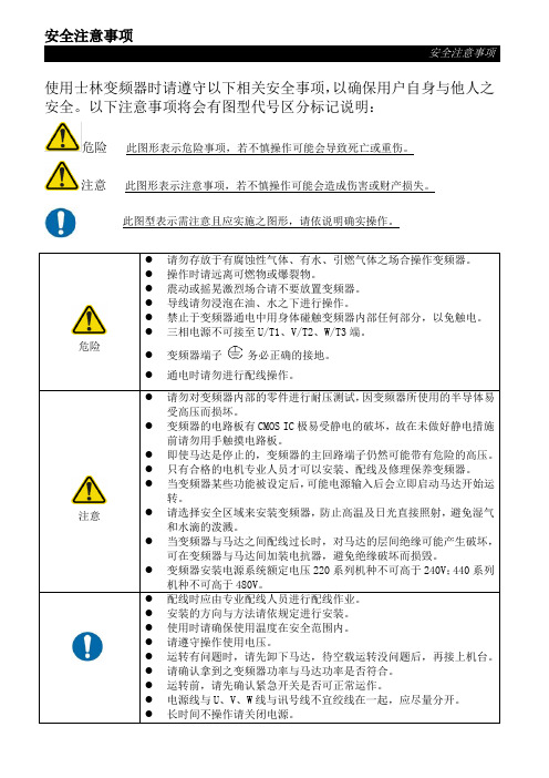
危险 注意
请勿存放于有腐蚀性气体、有水、引燃气体之场合操作变频器。 操作时请远离可燃物或爆裂物。 震动或摇晃激烈场合请不要放置变频器。 导线请勿浸泡在油、水之下进行操作。 禁止于变频器通电中用身体碰触变频器内部任何部分,以免触电。 三相电源不可接至 U/T1、V/T2、W/T3 端。
?当变频器与马达之间配线过长时对马达的层间绝缘可能产生破坏可在变频器与马达间加装电抗器避免绝缘破坏而损毁
安全注意事项
安全注意事项
使用士林变频器时请遵守以下相关安全事项,以确保用户自身与他人之 安全。以下注意事项将会有图型代号区分标记说明:
危险 此图形表示危险事项,若不慎操作可能会导致死亡或重伤。
注意 此图形表示注意事项,若不慎操作可能会造成伤害或财产损失。
2.1 铭牌说明 ................................................................................................................................................. 2 2.2 型号说明 ................................................................................................................................................. 2 2.3 订货代号说明.................................................................................
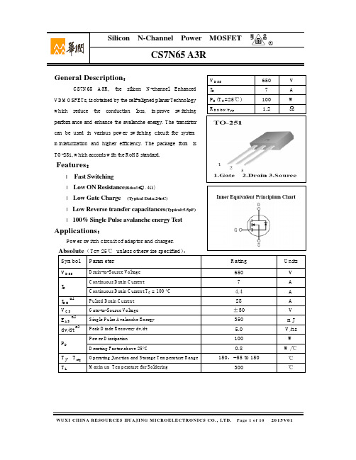
CS7N65 A3R
WUXI CHI NA RESOURCES HUAJ I NG M I CROELECTRONI CS C O., LTD. Pag e 3 of 1 0 20 15V0 1
TJ,Tstg TL
Drain-to-Source Voltage Continuous Drain Current Continuous Drain Current TC = 100 °C Pulsed Drain Current Gate-to-Source Voltage Single Pulse Avalanche Energy Peak Diode Recovery dv/dt Power Dissipation Derating Factor above 25°C Operating Junction and Storage Temperature Range Maximum Temperature for Soldering
Id , Drain Current , Amps
Isd, Reverse Drain Current , Amps
13.5
250us Pulse Test VDS=20V
9
4.5
+25℃
+150℃
CS7N65 A3R
○R
16
12
8
+150℃ +25℃
4
0
2
4
6
8
10
Vgs , Gate to Source Voltage , Volts
3.5
奥的斯XO端参数设置
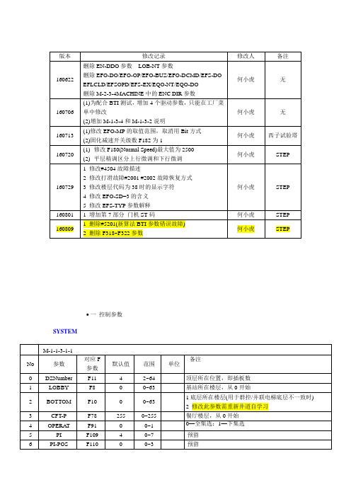
•一控制参数SYSTEM
OCSS
GROUP
DRIVE
DOORS
POS.REF
SERVICE(预留)
EMERG
SECURITY
TEST
TIME
REI
Speech(预留)
Remote(预留)
Factory
Position Indicator M-1-3-4
ALLOW CUDE M-1-3-2 Enable Masks
•二驱动参数MONITOR
EVENT LOG
SETUP
LEARN RUN
TEST
Factory
•三控制故障
说明:
1 对于计算次数的故障,次数在快车运行之前或15分钟之内都是累加的,当门区故障时,会判断累计的次数,若累计次数已经>=3次,则保护;当非门区故障时,会判断此时累加的次数,若累加次数已经>=5次,则保护。
2 关于故障次数累加
故障次数累加包含所有累计次数保护的故障,而不是只是针对某个故障。
如发生某个故障时有其他累计次数保护的故障发生,则故障次数也会累加。
3 关于故障次数清零条件
(1)保护之前,快车运行一次之后,累计的故障次数清零
(2)保护之前,15分钟之后,故障次数自动清零(包括控制故障和驱动故障)。
光缆测试报告【范本模板】
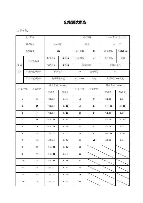
光缆测试报告工程名称:
光缆测试报告工程名称:
光缆测试报告工程名称:
光缆测试报告
工程名称:
光缆测试报告
工程名称:
光缆测试报告工程名称:
光缆测试报告工程名称:
光缆测试报告工程名称:
光缆测试报告工程名称:
光缆测试报告
工程名称:
光缆测试报告工程名称:
光缆测试报告
工程名称:
光缆测试报告工程名称:
光缆测试报告工程名称:
光缆测试报告工程名称:
光缆测试报告工程名称:
光缆测试报告工程名称:
光缆测试报告工程名称:
光缆测试报告
工程名称:
光缆测试报告工程名称:
光缆测试报告
工程名称:
光缆测试报告工程名称:
光缆测试报告工程名称:
光缆测试报告
工程名称:
光缆测试报告工程名称:。
部分加速度计型号参数

部分加速度计型号参数部分加速度计型号参数加速度传感器MXP7205VF MXP7205VF引脚低成本±5 G带SPI接口的双轴加速度计MXR6500G MXR6500G引脚薄型,低功耗±1.7克双轴加速度计,按比例输出KXTE9-1026 KXTE9-1026引脚±2g的三轴数字加速度计产品规格LSM320HAY30 LSM320HAY30引脚MEMS运动传感器模块的三维数字加速度计和2D间距和偏航模拟陀螺仪SCA830-D06 SCA830-D06引脚SCA830-D06单轴数字SPI接口的高性能加速度计,KXSS5-2057 KXSS5-2057引脚为±3克三轴加速度计产品规格ADIS16006 ADIS16006引脚双轴±5 g加速度计具有SPI接口的2240-002 2240-002引脚的模拟加速计模块KXP74 KXP74引脚 Kxp74系列加速度计和倾角传感器SCA3000-E01 SCA3000-E01 超低功耗引脚 SCA3000-E01 3轴加速度计,数字SPI接口KXTF9-4100 KXTF9-4100引脚±2g的三轴数字加速度计产品规格2430-002 2430-002引脚三轴模拟加速计模块KXPA4-2050 KXPA4-2050引脚±2 G三轴模拟加速度计产品规格SCA2100-D01 SCA2100-D01 SCA2100-D01 2轴加速度计,数字SPI接口引脚MXA2050A MXA2050A引脚低成本,±10 G双模拟输出三轴加速度计SCA3000-E05 SCA3000-E05 超低功耗引脚 SCA3000-E05 3轴加速度计,数字SPI接口MXR7150V MXR7150V引脚低成本?7 G按比例输出的双轴加速度计,MXR2010A MXR2010A引脚低成本,±35克双轴加速度计,按比例输出KXSC7-1050 KXSC7-1050引脚±2g的三轴模拟加速度计产品规格SCA3100-D03 SCA3100-D03 SCA3100-D03的3轴加速度计,数字SPI接口引脚MXA6500G MXA6500G引脚低成本,低噪音1 G双轴加速度计,绝对模拟输出SCA3060-D01 SCA3060-D01引脚 Sca3060-D01数位式低功率加速度计非安全关键汽车应用? 2012-002 2012-002引脚的模拟加速计模块MXD6125G MXD6125G引脚薄型,低功耗,±2 G双数字输出三轴加速度计MXR9500G MXR9500G引脚低成本±1.5 G三成比例的输出三轴加速度计KXTE9-2050 KXTE9-2050引脚±2g的三轴数字加速度计产品规格KXSS5-4457 KXSS5-4457引脚为±3克三轴加速度计产品规格2264-005 2264-005引脚的模拟加速计模块KXP84 KXP84引脚 Kxp84系列加速度计和倾角传感器SCA3100-D04 SCA3100-D04 SCA3100-D04 引脚高性能3轴加速度计,数字SPI接口SCA820-D04 SCA820-D04引脚 Sca820-D04 1轴高性能加速度计,数字SPI接口2460-002 2460-002引脚三轴模拟加速计模块格SCA820-D03 SCA820-D03引脚 Sca820-D03单轴加速度计,数字SPI接口BU-21771-000 BU-21771-000引脚BU系列加速BU-21771-000ADXL202E ADXL202E引脚低成本?2 G,占空比输出的双轴加速度计MXD2020E MXD2020E引脚超低噪声,低失调漂移±1 G双数字输出三轴加速度计KXR94-1050 KXR94-1050引脚±2g的三轴加速度计产品规格SCA3100-D07 SCA3100-D07 SCA3100-D07 引脚高性能3轴加速度计,数字SPI接口MX205Q MX205Q引脚低成本,5.0G,双模拟输出三轴加速度计ADXL202 ADXL202引脚低成本?2 G双轴加速度计,占空比输出MXR7250VW MXR7250VW引脚低成本±5 G双轴加速度计,按比例输出MXR6400Q MXR6400Q引脚超高性能为±1g双轴加速度计,按比例输出KXSD9-2050 KXSD9-2050引脚±2g的三轴数字加速度计产品规格SCA2100-D02 SCA2100-D02 SCA2100-D02 引脚 2轴高性能加速度计,数字SPI接口ADIS16003 ADIS16003引脚双轴±1.7 g加速度计具有SPI接口的2220-002 2220-002引脚的模拟加速计模块KXD94-2802 KXD94-2802引脚±10克三轴加速度计产品规格SCA3000-D02 SCA3000-D02引脚SCA3000-D02低功耗3轴加速度计,数字I 2 C接口KXTF9-1026 KXTF9-1026引脚±2g的三轴数字加速度计产品规格2422-002 2422-002引脚三轴模拟加速计模块KXPA4-1050 KXPA4-1050引脚±2 G三轴模拟加速度计产品规格SCA2110-D03 SCA2110-D03引脚 Sca2110-D03 2轴加速度计,数字SPI接口ADXL105 ADXL105引脚的高精度61克到65克单轴iMEMS加速度计与模拟输入KXPS5-2050 KXPS5-2050引脚±2g的三轴加速度计产品规格AIS326DQ的AIS326DQ引脚MEMS惯性传感器的3轴,带有数字输出的低g加速度计SCA3000-E04 SCA3000-E04 超低功耗引脚 SCA3000-E04 3轴加速度计,数字SPI接口? BU-23173-000 BU-23173-000引脚 BU系列加速BU-23173-000ADXL210E ADXL210E引脚低成本?10 G双轴加速度计,占空比MXD6125Q MXD6125Q引脚超高的性能为±1g双轴加速度计的数字输出KXR94-2353 KXR94-2353引脚±2g的三轴数字加速度计产品规格MXA2500J MXA2500J引脚超低成本,1.0 G绝对值输出的双轴加速度计,SCC1300-D04 SCC1300-D04引脚 Scc1300-D04组合的陀螺仪和3轴加速度计,数字SPI接口? 2010-002 2010-002引脚数字加速计模块MXP7205VW MXP7205VW引脚低成本±5 G带SPI接口的双轴加速度计MXR9150G MXR9150G引脚低成本±5克三成比例的输出三轴加速度计KXTE9-1050 KXTE9-1050引脚±2g的三轴数字加速度计产品规格KXSS5-3028 KXSS5-3028引脚为±3克三轴加速度计产品规格2260-002 2260-002引脚的模拟加速计模块KXP74-1050 KXP74-1050引脚±2g的三轴数字加速度计产品规格SCA3000-E02 SCA3000-E02引脚 SCA3000-E02的3轴加速度计,数字I 2 C接口超低功耗? 2440-002 2440-002引脚三轴模拟加速计模块KXPB5-2050 KXPB5-2050引脚±2 G三轴加速度计产品规格SCA830-D05 SCA830-D05引脚SCA830-D05单轴加速度计,数字SPI接口ADXL190 ADXL190引脚低成本6100 G单轴加速度计的模拟输出MXC62020GP MXC62020GP引脚低功耗,薄型±2 G双I 2 C接口的三轴加速度计KXPS5-4457 KXPS5-4457引脚±3G的三轴加速度计产品规格CMA3000-D01 CMA3000-D01引脚 CMA3000-D01的3轴超低功耗加速度计,数字SPI和I 2 C接口MXR7305VF MXR7305VF引脚改进的低成本±5 G双成比例的模拟输出三轴加速度计MXR6150M MXR6150M引脚薄型,低功耗±5g的双轴加速度计,按比例输出KXSD9-1026 KXSD9-1026引脚±2g的三轴数字加速度计产品规格SCA2120-D07 SCA2120-D07引脚 Sca2120-D07 2轴加速度计,数字SPI接口MXD202 MXD202引脚低成本,2.0G,双数字输出三轴加速度计SCA3060-D02 SCA3060-D02引脚 Sca3060-D02数位式低功率加速度计非安全关键汽车应用? 2210-002 2210-002引脚的模拟加速计模块KXD94 KXD94引脚 KXD94系列加速计和倾斜计SCA3000-D01 SCA3000-D01引脚SCA3000-D01低功耗3轴加速度计,数字SPI接口KXTE9-4100 KXTE9-4100引脚±2g的三轴数字加速度计产品规格ML8953 ML8953 的3轴加速度计的数字量输出引脚数据KXR94-2283 KXR94-2283引脚,多项数据表为±2G三轴的加速度计产品规格2420-002 2420-002引脚三轴数字加速计模块KXP94 KXP94引脚 Kxp94系列加速度计和倾角传感器SCA2120-D05 SCA2120-D05引脚 Sca2120-D05 2轴加速度计,数字SPI接口ADXL05 ADXL05引脚 61 G 65 G的单芯片加速度计与信号调理2470-002 2470-002引脚三轴模拟加速计模块KXPS5-1050 KXPS5-1050引脚±2g的三轴加速度计产品规格AIS226DS AIS226DS引脚 MEMS惯性传感器的2轴,低g加速度计的数字量输出SCA810-D01 SCA810-D01引脚 Sca810-D01单轴加速度计,数字SPI接口BU-23842-000 BU-23842-000引脚BU系列加速BU-23842-000MMA7455 MMA7455 MMA7455引脚 3轴加速度计模块ADXL50 ADXL50引脚单片加速度传感器与信号调理MXD6025Q MXD6025Q引脚超低噪声,低失调漂移±1 G双数字输出三轴加速度计KXR94-2050 KXR94-2050引脚±2g的三轴加速度计产品规格MPXY8300 MPXY8300引脚根部分号码汽车压力范围卡车轮胎压力范围压力范围压力传感器精度* Z-轴加速度计测量范围Z-轴加速度计精度X轴加速度计测量范围X轴加速度计精度AcceleMXA2500G MXA2500G引脚改进,超低噪声1.7克双轴加速度计具有绝对的输出SCC1300-D02 SCC1300-D02引脚 Scc1300-D02组合的陀螺仪和3轴加速度计,数字SPI接口? ADXL210 ADXL210引脚低成本?10 G双轴加速度计,占空比1221L-002 1221L-002引脚的低噪声模拟加速度计引脚 1.5克MMA7368L MMA7368L三轴低g微机械加速度计LIS2L06AL LIS2L06AL引脚MEMS惯性传感器的2轴- + / - 2g/6g超小型线性加速度计ADXL327 ADXL327引脚小尺寸,低功耗,3轴±2 g加速度计MMA7330L MMA7330L引脚4克,12克三轴低g微机械加速度计MMA7341LC MMA7341LC引脚 3G,11克三轴低g微机械加速度计4203 4203引脚型号4203加速度计MMA2300 MMA2300引脚表面贴装微机械加速度计MLX90308 MLX90308引脚可编程的通用传感器接口MMA1220KEG MMA1220KEG引脚低g微机械加速度计LIS3L02AS5 LIS3L02AS5引脚 MEMS惯性传感器3轴- ?2g/6g 线性加速度计MMA3201D MMA3201D引脚表面贴装微机械加速度计MMA6261Q MMA6261Q的引脚 Mma6261q加速度传感器MMA8452Q MMA8452Q,,引脚 3轴,12-bit/8-bit,,数字加速度计3031-050 3031-050引脚型号3031加速度计4610-020-060 4610-020-060引脚型号4610加速度计MMAS40G10D MMAS40G10D引脚微机械加速度计SCA610-CAHH1G SCA610-CAHH1G引脚SCA610-cahh1g 1轴模拟测斜仪MAX1459 MAX1459引脚 MAX1459 2线,4-20mA的智能信号调理KXRB5-2050 KXRB5-2050引脚,多项数据表为±2G三轴的加速度计ADXL335 ADXL335引脚小尺寸,低功耗,3轴±3 g加速度计MMA1270KEG MMA1270KEG引脚飞思卡尔半导体技术资料MMA2204KEG MMA2204KEG引脚表面贴装微机械加速度计LIS2L01 LIS2L01引脚,多项数据表的惯性传感器2axis/1g线性加速度计MMA2204D MMA2204D引脚表面贴装微机械加速度计HMR3400 HMR3400引脚数字罗盘解决方案QA-1400 QA-1400引脚加速度计具有成本效益级惯性传感器ADXL213 ADXL213引脚低成本±1.2克双轴加速度计4655-020 4655-020引脚型号4655加速度计4801A 0010 4801A-0010引脚型号4801a加速度计MMA1212 MMA1212引脚表面贴装微机械加速度计BMA145 BMA145引脚 Bma145数据表B Bma145三轴模拟加速度传感器LIS344AL的LIS344AL引脚MEMS惯性传感器的3轴超小型线性加速度计ADXL150 ADXL150引脚 65克到650克,低噪声,低功耗,单/双通道轴的iMEMS?加速度计MMA2260D和 MMA2260D引脚 1.5克X-轴微机械加速度计MMA2301KEG MMA2301KEG引脚表面贴装微机械加速度计LIS352AX的 LIS352AX引脚 MEMS惯性传感器的3轴- ±2g的绝对模拟输出加速度计1203-1000-10-072X 1203-1000-10-072X引脚型号1203加速度计MMA1212D MMA1212D引脚表面贴装微机械加速度计MLX90308CAB MLX90308CAB引脚可编程传感器接口52M30-2000-360 52M30-2000-360引脚型号52m30加速度计ADXL323 ADXL323引脚小尺寸,低功耗,2轴±3 GI MEMS加速度计MLX90308CCC MLX90308CCC引脚可编程传感器接口MMA7341L MMA7341L引脚 3G,11克三轴低g微机械加速度计LIS2L02AQ LIS2L02AQ引脚惯性传感器2axis - 2g/6g线性加速度计ADXL345 ADXL345引脚三轴±2/4/8/16g数字加速度计MMA2244EG MMA2244EG引脚低g微机械加速度计MMA6341L MMA6341L引脚 3G,11克两轴低g微机械加速度计LIS302SG LIS302SG引脚 MEMS运动传感器的3轴- ?2G模拟输出短笛加速度计4000A-020-060 4000A-020-060引脚型号4000A加速度计MMA1201P MMA1201P引脚微机械加速度计ADXL193 ADXL193引脚单轴,高g,公司的iMEMS加速度计MMA7660FC MMA7660FC引脚 3轴方向/运动检测传感器LIS3L02AQ3 LIS3L02AQ3引脚 MEMS惯性传感器的3轴- 2G /6克线性加速度计ADW22035 ADW22035引脚精度±18 G Single-/dual-axis iMEMS加速度计MMA7360L MMA7360L引脚 1.5G,6克三轴低g微机械加速度计MAX1166 MAX1166引脚低功耗,16位模拟数字转换器,并行接口MMA6851QR2 MMA6851QR2引脚单轴SPI惯性传感器NJU7029 NJU7029引脚低噪声,轨至轨输出双通道CMOS运算放大器4602-010-060 4602-010-060引脚型号4602加速度计MMA6270Q MMA6270Q引脚 R1.5 G - 6 G双三轴低g微机械加速度计SCA610-C23H1A SCA610-C23H1A引脚的 SCA610-c23h1a单轴模拟加速度计ADIS16355, ADIS16355引脚三轴惯性传感器ADXL312 ADXL312引脚三轴,±1.5g/3g/6g/12g数字加速度计MMA2202KEG MMA2202KEG引脚表面贴装微机械加速度计LIS3L02AQ LIS3L02AQ引脚惯性传感器3轴- 2g/6g线性加速度计MMA2202D MMA2202D引脚表面贴装微机械加速度计BU1511KV2 BU1511KV2引脚事件数据记录系统LSIQA3000-030 QA3000-030引脚的 Q-Flex QA-3000加速度计ADS8201 ADS8201引脚 2.2V至5.5V,低功耗,12位,100ksps时,与PGA和SPI?接口的8通道数据采集系统3058-010-P 3058-010-P引脚型号3058加速度计4623-025-060 4623-025-060引脚型号4623加速度计XMMA1000P XMMA1000P引脚微机械加速度计LIS244AL LIS244AL引脚 MEMS运动传感器的2轴- ?2克超小型线性加速度计KXPS5 KXPS5引脚加速度计和倾角传感器ADIS16354 ADIS16354引脚高精度三轴惯性传感器MMA7261QT和 MMA7261QT引脚 2.5G - 10G三轴低g微机械加速度计MMA6222AKEG MMA6222AKEG引脚模拟双轴微机械加速度计“惯性传感器LIS3L02AS LIS3L02AS引脚 3轴- 2g/6g线性加速度计MMA1210D MMA1210D引脚表面贴装微机械加速度计HMC1055 HMC1055引脚 3轴罗盘传感器集QA-700 QA-700引脚加速度计的经济温度补偿传感器ADXL320 ADXL320引脚小而薄的±5 G iMEMS加速度计834M1-2000, 834M1-2000引脚型号834m1加速度计MMA2260 MMA2260引脚 1.5克X-轴微机械加速度计LIS332AR LIS332AR引脚 MEMS运动传感器的3轴±2 G模拟输出超小型加速度计LIS3LV02DL LIS3LV02DL引脚 MEMS惯性传感器的3轴-2G /??6克数字输出低电压,线性加速度计MMA1270D MMA1270D引脚低g微机械加速度计MMA2244KEG MMA2244KEG引脚低g微机械加速度计LIS33DE LIS33DE引脚 MEMS运动传感器的3轴- ±2克/±8G智能数字输出“纳米”加速度1207F-1000 1207F-1000引脚型号1207f加速度计MMA1200D MMA1200D引脚表面贴装微机械加速度计邢树村整理:TEL:189********。
MITSUBISHI CM50MX-24A 说明书
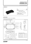
HIGH POWER SWITCHING USEHIGH POWER SWITCHING USEELECTRICAL CHARACTERISTICS (T j = 25°C, unless otherwise specified)INVERTER PARTLimitsUnitMin.Typ.Max.I CESV GE(th)I GESV CE(sat)C iesC oesC resQ Gt d(on)t rt d(off)t ft rr (Note.3) Q rr (Note.3)V EC(Note.3)R th(j-c)Q R th(j-c)RR GintR G Collector cutoff currentGate-emitter threshold voltageGate leakage currentCollector-emitter saturationvoltageInput capacitanceOutput capacitanceReverse transfer capacitanceTotal gate chargeTurn-on delay timeTurn-on rise timeTurn-off delay timeTurn-off fall timeReverse recovery timeReverse recovery chargeEmitter-collector voltageThermal resistance(Junction to case)Internal gate resistanceExternal gate resistanceV CE = V CES, V GE = 0VI C = 5mA, V CE = 10V±V GE = V GES, V CE = 0VI C = 50A, V GE = 15VI C = 50A, V GE = 15VV CE = 10VV GE = 0VV CC = 600V, I C = 50A, V GE = 15VV CC = 600V, I C = 50AV GE = ±15V, R G = 6.2ΩInductive load(I E = 50A)I E = 50A, V GE = 0VI E = 50A, V GE = 0Vper 1/6 IGBTper 1/6 free wheeling diodeT C = 25°C, per switch—7—2.02.21.9———250—————22.62.162.5———180.52.6——8.50.750.17—10050300600200—3.4——0.350.63—62—6————————————————————6mAVμAVnFnCnsμCVK/WΩT j = 25°CT j = 125°CChip(Note. 6)(Note. 1)(Note. 6)T j = 25°CT j = 125°CChip(Note. 6)Symbol Parameter ConditionsBRAKE PARTLimitsUnitMin.T yp.Max.I CESV GE(th)I GESV CE(sat)C iesC oesC resQ GI RRM(Note.3) V FM(Note.3)R th(j-c)QR th(j-c)RR GintR G Collector cutoff currentGate-emitter threshold voltageGate leakage currentCollector-emitter saturationvoltageInput capacitanceOutput capacitanceReverse transfer capacitanceT otal gate chargeRepetitive peak reverse currentForward voltage dropThermal resistance(Junction to case)Internal gate resistanceExternal gate resistanceV CE = V CES, V GE = 0VI C = 3mA, V CE = 10V±V GE = V GES, V CE = 0VI C = 30A, V GE = 15VI C = 30A, V GE = 15VV CE = 10VV GE = 0VV CC = 600V, I C = 30A, V GE = 15VV R = V RRMI F = 30AI F = 30Aper IGBTper Clamp diodeT C = 25°C—7—2.02.21.9———150—2.62.162.5———180.52.6——5.10.450.1—13.4——0.480.79—100—6———————————————10mAVμAVnFnCmAVK/WΩT j = 25°CT j = 125°CChip(Note. 6)(Note. 1)(Note. 6)T j = 25°CT j = 125°CChip(Note. 6)Symbol Parameter ConditionsI RRM V FR th(j-c) Repetitive peak reverse currentForward voltage dropThermal resistance(Junction to case)V R = V RRM, T j = 150°CI F = 50Aper Diode—1.2—61.60.33———mAVK/W (Note. 1)LimitsUnitMin.T yp.Max.Symbol Parameter Conditions CONVERTER PARTHIGH POWER SWITCHING USEHIGH POWER SWITCHING USEHIGH POWER SWITCHING USEHIGH POWER SWITCHING USEHIGH POWER SWITCHING USE。
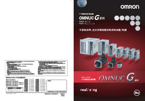
欧姆龙伺服电机
0./6$(
$90OF7
$9%SJWF
1$ 1-$
$9%SJWF
/$
0./6$(
OMNUC G
3
8 L8
3000 2000 1000
50W 300W 900W 1kW 3kW 5kW 6kW 7.5kW
7.5kW
1500r/min
(r/min)
"$
0./6$( "$ 3%(ƾƾ;∗
3"$"(ƾƾƾƾ4 3"$"(ƾƾƾƾ#
3"$"(ƾƾƾƾ43 3"$"(ƾƾƾƾ#3
"$
3.(ƾ;
ซὙ(1ጆѴԵࠪःᑡу˘ᣤЙnj
8 8 3"$3(ƾƾƾƾ$
2
1
2
3
FQM1
OMNUC G
5
3%(5
0./6$( .&$)"530-*/,
3%(/ƾ.-
4."3545&1 3%#1
"$7
"$7
"$7
8
8
8
8
8
8
8
8
8
8
8
8
4."3545&1 3.(
8 8 8 8 8 8
L8 L8
L8 L8 L8 L8 L8 L8 L8
SNJO
*/$ "#4
*/$
*/$ "#4
*/$
*/$ "#4
*/$
西门子兰系列接触器选型手册
PS* 每个购买 单位的大 约重量2)
kg
1 件 0.300 1 件 0.304 1 件 0.302 1 件 0.303 1 件 0.303 1 件 0.304 1 件 0.305 1 件 0.370 1 件 0.368 1 件 0.369 1 件 0.371 1 件 0.371 1 件 0.372 1 件 0.375 1 件 0.370 1 件 0.376 1 件 0.374 1 件 0.374 1 件 0.375 1 件 0.374 1 件 0.382 1 件 0.376 1 件 0.378 1 件 0.382
2) 重量是指包括辅助触头的型号。
辅助触头可单独订货(参见“安装附件”)。
* 以该数量或该数量的倍数订购。
1/2
3RV5 电动机保护断路器
用于电机起动组合
选型与订货数据
不带辅助触头 规格 S0
规格 S2 规格 S3
额定电流 适用于感应 热过载脱扣器 瞬时电子式
电机1),带 P 的整定范围
脱扣器
▲
短路分断能力, PTS 螺钉型接线端子
不适用
325
50
32
15
不适用
416
50
40
18.5
不适用
520
50
45
22
不适用
585
50
50
22
不适用
650
50
●
3RV53 31-4AC10
●
3RV53 31-4BC10
●
3RV53 31-4DC10
●
3RV53 31-4EC10
●
3RV53 31-4FC10
●
3RV53 31-4GC10
2415喇叭规格书

SPECIFICATION FOR APPROV AL承认书Customer (客户):深鑫Product Name(产品名称):Micro Dynamic SpeakerLiu Sheng Part No.恒合型号: LS2415R-01薄Specification(规格): 8Ω1.5WCustomer’s Model No.(客户型号):Specification No.(规格书编号):Number of the edition(版本号):A0CUSTOMER’S APPROVED SIGNATURE客户承认盖章Approved by核准Checked by审核Issued by制成东莞市刘生电子有限公司DONG GUAN LIU SHENG ELECTRONICS. CO.,LTD地址:东莞市塘厦镇田心塘龙西路92号金磊工业区A栋3楼请确认后回传PLEASE REPL Y AFTER APPROV AL东莞市刘生电子有限公司DONG GUAN LIU SHENG ELECTRONICS. CO.,LTD PAGE NO.页码2/8PART . NO.产品型号2415R-01薄A、目录 TABLE OF CONTENTS目录TABLE OF CONTENTS序号NO. 项目ITEM 页码PAGE 封面COVER 1A 目录TABLE OF CONTENTS 2B 修订记录 REVISIONS RECORD 3C 适用范围SCOPE 4D 一般规范GENERAL SPECIFICATIONS 4E 机械特性 MECHANICAL CHARACTERISTICS 5F 信赖性试验 RELIABILITY TEST 6G 环境试验 ENVIRONMENTAL TEST 6H 结构STUCTURE7I 外观尺寸图 APPEARANCE DRAWING 8东莞市刘生电子有限公司DONG GUAN LIU SHENG ELECTRONICS. CO.,LTD页码3/8 PART . NO.产品型号2415R-01薄B、修订记录REVISIONS RECORDREVISION版本DATE日期CHANGE NOTE变更内容DESD.BY修订人APPD.BY确认人无变更则此页不用填写东莞市刘生电子有限公司DONG GUAN LIU SHENG ELECTRONICS. CO.,LTD页码4/8PART . NO.产品型号2415R-01薄C、适用范围SCOPEThis specification applies speaker,2415R-01薄此规格书适用于喇叭,2415R-01薄D、GENERAL SPECIFICATIONS 一般规格NO. Item Symbol Unit Specification Condition1 Dimension 尺寸mm 24×15×3.22Rate/Max Power Rating额定/最大功率W Rate 1.5/Max.1.8Max. Power:IEC-60268-5Filter 60s On/120s Off10 Cycles(Room TEMP.)3AC Impedance交流阻抗ΩOhm 8±15% At1.0KHz 1.0V 4DC Resistance直流阻抗ΩOhm 7.8±10%5Resonance Frequency谐振频率Fo Hz 600±20% At 1.0V6Output S.P.L输出音压S.P.L dB 120±3dB 1.0 KHz7Frequency Rang有效频宽Hz Fo—20KOutput S.P.L ±10dB输出音压±10dB8Max Distortion最大失真% 10% At 1.0KHz 1.5W 9Magnet Material磁铁材质mm Nd-Fe-B10Storage temp贮存温度℃-20~+55℃11Operate temp工作温度℃-20~+55℃12Buzze&Rattle异常音Not be audible at 3.5V sine wave between Fo~4.0KHz 输入 3.5V正弦波Fo到4.0KHz之间无异常音13Protection Regulation环保法规RoHS东莞市刘生电子有限公司DONG GUAN LIU SHENG ELECTRONICS. CO.,LTD页码5/8 PART . NO.产品型号2415R-01薄E、MECHANICAL CHARACTERISTICS机械特性NO Item Test condition Evaluation standard1 Vibration Test振动测试Speaker shall be measured after being appliedvibration of amplitude of 1.5mm with 10 to55Hz band of ibration frequency to each of 3per-pendicular directions for 2 hours.振动周波数10~55Hz,全振幅1.5mm于X,Y,Z 3个方向各2个小时No obstacle to be harmful tomormal operation ;Damages,cracks,rusts anddistortions.Should not be audible at 3.5Vsinewave between FO~4.0kHz测试后无任何障碍防碍正常操作,且在输入3.5V正弦波从Fo到4.0KHz之间无异常音。
安特尔AT24C32D 32K Serial EEPROM数据手册说明书
AT24C32DI2C-Compatible (2-Wire) Serial EEPROM32-Kbit (4,096 x 8)DATASHEET Features●Low-voltage and Standard-voltage OperationV CC = 1.7V to 5.5V●Internally Organized as 4,096 x 8 (32K)●I2C-compatible (2-Wire) Serial Interface●Schmitt Trigger, Filtered Inputs for Noise Suppression●Bidirectional Data Transfer Protocol●400kHz (1.7V) and 1MHz (2.5V, 2.7V, 5.0V) Compatibility●Write Protect Pin for Hardware Protection●32-byte Page Write ModePartial Page Writes Allowed●Self-timed Write cycle (5ms Max)●High ReliabilityEndurance: 1,000,000 Write CyclesData Retention: 100 Years●Lead-free/Halogen-free devices Available●Green Package Options (Pb/Halide-free/RoHS Compliant)8-lead JEDEC SOIC, 8-lead TSSOP, 8-pad UDFN, 8-pad XDFN, 5-leadSOT23, 5-ball WLCSP, and 8-ball VFBGA packages●Die Sale Options: Wafer Form, Waffle Pack, and Bumped Wafers DescriptionThe Atmel® AT24C32D provides 32,768 bits of Serial Electrically Erasable and Programmable Read-Only Memory (EEPROM) organized as 4,096 words of 8 bits each. The device’s cascading feature allows up to eight devices to share a common 2-wire bus. The device is optimized for use in many industrial and commercial applications where low-power and low-voltage operation are essential. The devices are available in space-saving 8-lead JEDEC SOIC, 8-lead TSSOP, 8-pad UDFN, 8-pad XDFN, 5-lead SOT23, 5-ball WLCSP, and 8-ball VFBGA packages. In addition, this device operates from 1.7V to 5.5V.AT24C32D [DATASHEET]Atmel-8866D-SEEPROM-AT24C32D-Datasheet_12201621.Pin Configurations and PinoutsTable 1-1.Pin Configuration Note:When using the 5-lead SOT-23 or the 5-ball WLCSP , the software bits A2, A1, and A0 must be set to Logic 0 to properly communicate with the device.2.Absolute Maximum Ratings*8-pad UDFN/XDFNV CC WP SCL SDAA 0A 1A 2GND123487658-ball VFBGABottom View8-lead SOIC8-lead TSSOPTop View12348765A 0A 1A 2GNDV CC WP SCL SDATop View Top ViewA 0A 1A 2GND V CC WP SCL SDA87651234SCL GND SDA123545-lead SOT23WPV CC* Note: Drawings are not to scale5-ball WLCSPBall Side View(1)A 0A 1A 2GNDV CC WP SCL SDA12348765(1)Operating Temperature . . . . . . . . . . .-55°C to +125°C Storage Temperature . . . . . . . . . . . . -65°C to + 150°C Voltage on any pinwith respect to ground . . . . . . . . . . . . . . .-1.0 V +7.0V Maximum Operating Voltage . . . . . . . . . . . . . . . 6.25V DC Output Current. . . . . . . . . . . . . . . . . . . . . . .5.0mA*Notice:Stresses beyond those listed under “AbsoluteMaximum Ratings” may cause permanent damage to the device. This is a stress rating only and functional operation of the device at these or any other conditions beyond those indicated in the operational sections of this specification are not implied. Exposure to absolute maximum rating conditions forextended periods may affect device reliability.3AT24C32D [DATASHEET]Atmel-8866D-SEEPROM-AT24C32D-Datasheet_1220163.Block Diagram4.Pin DescriptionsSerial Clock (SCL): The SCL input is used to positive-edge clock data into each EEPROM device and negative-edge clock data out of each device.Serial Data (SDA): The SDA pin is bidirectional for serial data transfer. This pin is open drain driven and may be wire-ORed with any number of other open-drain or open-collector devices.Device Addresses (A 2, A 1, A 0): The A 2, A 1, and A 0 pins are device address inputs that are hard wired (directly to GND or to V CC ) for compatibility with other Atmel AT24C devices. When the pins are hard wired, as many as eight 32K devices may be addressed on a single bus system. (Device addressing is discussed in detail in Section 7., “Device Addressing” on page 9). A device is selected when a corresponding hardware and software match is true. If these pins are left floating, the A 2, A 1, and A 0 pins will be internally pulled down to GND. However, due to capacitive coupling that may appear during customer applications, Atmel recommends always connecting the address pins to a known state. When using a pull-up resistor, Atmel recommends using 10k Ω or less.Write Protect (WP): The Write Protect input, when connected to GND, allows normal write operations. When WP is connected directly to V CC , all Write operations to the memory are inhibited. If the pin is left floating, the WP pin will be internally pulled down to GND; however, due to capacitive coupling that may appear during customerapplications, Atmel recommends always connecting the WP pins to a known state. When using a pull-up resistor, Atmel recommends using 10k Ω or less.Table 4-1.Write ProtectV CC GND WP SCL SDAA 2A 1A 0AT24C32D [DATASHEET]Atmel-8866D-SEEPROM-AT24C32D-Datasheet_12201645.Memory OrganizationAT24C32D, 32K Serial EEPROM : The 32K is internally organized as 128 pages of 32-bytes each. Random word addressing requires a 12-bit data word address.5.1Pin CapacitanceTable 5-1.Pin Capacitance (1)Note:1.This parameter is characterized and is not 100% tested.5.2DC CharacteristicsTable 5-2.DC CharacteristicsNote:1.V IL min and V IH max are reference only and are not tested.Applicable over recommended operating range from: T A = 25°C, f = 1.0MHz, V CC = 5.5V.Applicable over recommended operating range from: T AI = -40°C to +85°C, V CC = 1.7V to 5.5V (unless otherwise noted).5AT24C32D [DATASHEET]Atmel-8866D-SEEPROM-AT24C32D-Datasheet_1220165.3AC CharacteristicsTable 5-3.AC Characteristics (Industrial Temperature)Notes:1.This parameter is ensured by characterization and is not 100% tested.2.AC measurement conditions:●R L (connects to V CC ): 1.3k Ω (2.5V, 5.5V), 10k Ω (1.7V)●Input pulse voltages: 0.3V CC to 0.7V CC ●Input rise and fall times: ≤ 50ns ●Input and output timing reference voltages: 0.5 x V CCApplicable over recommended operating range from: T AI = -40°C to +85°C, V CC = 1.7V to 5.5V, CL = 100pF (unless otherwise noted). Test conditions are listed in Note 2.AT24C32D [DATASHEET]Atmel-8866D-SEEPROM-AT24C32D-Datasheet_12201666.Device OperationClock and Data Transitions: The SDA pin is normally pulled high with an external device. Data on the SDA pin may change only during SCL low time periods. Data changes during SCL high periods will indicate a Start or Stop condition as defined below.Figure 6-1.Data ValidityStart Condition : A high-to-low transition of SDA with SCL high is a Start condition that must precede every command.Stop Condition: A low-to-high transition of SDA with SCL high is a Stop condition. After a Read sequence, the Stop condition will place the EEPROM in a standby power mode.Figure 6-2.Start Condition and Stop Condition DefinitionSDASCLData ChangeData StableData StableSDASCLStart Condition Stop Condition7AT24C32D [DATASHEET]Atmel-8866D-SEEPROM-AT24C32D-Datasheet_122016Acknowledge: All addresses and data words are serially transmitted to and from the EEPROM in 8-bit words. The receiving device sends a zero during the ninth clock cycle to acknowledge that it has received each word. This zero response is referred to as an Acknowledge.Figure 6-3.Output AcknowledgeStandby Mode: AT24C32D features a low-power standby mode that is enabled upon power-up and after the receipt of the Stop condition and the completion of any internal operations.Software Reset : After an interruption in protocol, power loss or system reset, any 2-wire part can be protocol reset by following these steps:1.Create a Start condition (if possible).2.Clock nine cycles.3.Create another Start condition followed by Stop condition as shown below.The device should be ready for the next communication after above steps have been completed. In the event that the device is still non-responsive or remains active on the SDA bus, a power cycle must be used to reset the device.Figure 6-4.Software ResetSCLData InData OutStart ConditionAcknowledge981SCLSDAAT24C32D [DATASHEET]Atmel-8866D-SEEPROM-AT24C32D-Datasheet_1220168Figure 6-5.Bus TimingFigure 6-6.Write Cycle TimingNote: 1.The Write cycle time t WR is the time from a valid Stop condition of a Write sequence to the end ofthe internal Clear/Write cycle.SCLSDA InSDA OutSCLSDAStop ConditionStart Condition9AT24C32D [DATASHEET]Atmel-8866D-SEEPROM-AT24C32D-Datasheet_1220167.Device AddressingThe 32K EEPROM requires an 8-bit device address word following a Start condition to enable the chip for a Read or Write operation. The device address word consists of a mandatory ‘1010’ sequence for the first four most significant bits which is known as the device type identifier. These four bits are bit 7, bit 6, bit 5, and bit 4 as seen in Figure 7-1. This is common to all 2-wire Serial EEPROM devices.The next three bits are the A2, A1, and A0 hardware address select bits which allow as many as eight devices on the same bus. These bits must compare to their corresponding hard wired input pins, A 2, A 1, and A 0. The A 2, A 1, and A 0 pins use an internal proprietary circuit that biases them to a logic low condition if the pins are allowed to float.When utilizing the 5-ball WLCSP or the 5-lead SOT-23 packages, the A 2, A 1, and A 0 pins are not available. The A 2, A 1, and A 0 pins are internally pulled to ground and thus the A2, A1, and A0 device address bits must always be set to a Logic 0 to communicate with the device. This condition is depicted in Figure 7-1 below.The eighth bit of the device address is the Read/write operation select bit. A Read operation is initiated if this bit is a Logic 1, and a Write operation is initiated if this bit is a Logic 0.Upon a successful comparison of the device address, the EEPROM will output a zero during the following clock cycle. If a compare is not made, the device will not acknowledge and will instead return to a standby state.Figure 7-1.Device AddressingData Security: The AT24C32D has a hardware data protection scheme that allows the user to write protect the whole memory when the WP pin is at V CC .AT24C32D [DATASHEET]Atmel-8866D-SEEPROM-AT24C32D-Datasheet_122016108.Write OperationsByte Write : A Write operation requires two 8-bit data word addresses following the device address word and acknowledgment. Upon receipt of this address, the EEPROM will again respond with a zero then clock in the first 8-bit data word. Following receipt of the 8-bit data word, the EEPROM will output a zero. The addressing device, such as a microcontroller, must then terminate the write sequence with a Stop condition. At this time, the EEPROM enters an internally-timed Write cycle, t WR , to the nonvolatile memory (See Figure 6-6). All inputs are disabled during this Write cycle and the EEPROM will not respond until the Write is complete.Figure 8-1.Byte WriteNote:* = Don’t care bit.Page Write: The 32K EEPROM is capable of 32-byte Page Writes.A Page Write is initiated the same way as a Byte Write, but the microcontroller does not send a Stop condition after the first data word is clocked in. Instead, after the EEPROM acknowledges receipt of the first data word, the microcontroller can transmit up to 31 more data words. The EEPROM will respond with a zero after each data word received. The microcontroller must terminate the Page Write sequence with a Stop condition.The data word address lower five bits are internally incremented following the receipt of each data word. The higher data word address bits are not incremented, retaining the memory page row location. When the word address, internally generated, reaches the page boundary, the following byte is placed at the beginning of the same page. If more than 32 data words are transmitted to the EEPROM, the data word address will roll-over and the previously loaded data will be altered. The address roll-over during Write is from the last byte of the current page to the first byte of the same page.Figure 8-2.Page WriteNote:* = Don’t care bit.Acknowledge Polling : Once the internally-timed Write cycle has started and the EEPROM inputs are disabled, acknowledge polling can be initiated. This involves sending a Start condition followed by the device address word. The Read/Write bit is representative of the operation desired. Only if the internal Write cycle has completed will the EEPROM respond with a zero, allowing the Read or Write sequence to continue.S T A R TW R I T ES T O PDevice Address FirstWord Address Second Word AddressDataSDA LineM S BA C KR /W A C KA C KA CKSDA LineS T A W R I BK/W KKKKS T9.Read OperationsRead operations are initiated the same way as Write operations with the exception that the Read/Write select bit in the device address word is set to one. There are three Read operations:●Current Address Read ●Random Address Read ●Sequential ReadCurrent Address Read : The internal data word address counter maintains the last address accessed during the last Read or Write operation, incremented by one. This address stays valid between operations as long as the chip power is maintained. The address roll-over during read is from the last byte of the last memory page, to the first byte of the first page.Once the device address with the Read/Write select bit set to one is clocked in and acknowledged by theEEPROM, the current address data word is serially clocked out. The microcontroller does not respond with an zero but does generate a Stop condition.Figure 9-1.Current Address ReadRandom Read: A Random Read requires a dummy Byte Write sequence to load in the data word address. Once the device address word and data word address are clocked in and acknowledged by the EEPROM, the microcontroller must generate another Start condition. The microcontroller now initiates a Current Address Read by sending a device address with the Read/write select bit high. The EEPROM acknowledges the device address and serially clocks out the data word. The microcontroller does not respond with a zero but does generate a Stop condition.Figure 9-2.Random ReadNote:* = Don’t care bit.SDA LineS T A R TDevice AddressR E A DS T O PM S BA C KR /W N O A C KDataSDA LINES T A R TS T A R TR E A DW R I T ES T O PDevice Address Second Word Address Device AddressFirst Word Address Data (n)M S BA C KA C KAC KL S B A C KN O A C KR /W Dummy WriteR /W12Sequential Read: Sequential Reads are initiated by either a Current Address Read or a Random Address Read. After the microcontroller receives a data word, it responds with an acknowledge. As long as the EEPROM receives an acknowledge, it will continue to increment the data word address and serially clock out sequential data words. When the memory address maximum address is reached, the data word address will roll-over and the Sequential Read will continue from the beginning of the array. The Sequential Read operation is terminated when the microcontroller does not respond with a zero but does generate a Stop condition.Figure 9-3.Sequential ReadNote:* = Don’t care bit.SDA LINESTARTSTARTREADWRITESTOP DeviceAddressSecond WordAddressDeviceAddressFirst WordAddressData (n + 1)Data (n + 2)Data (n + x)Data (n)MSBACKACKACKLSBACKACKACKACKNOACKR/WDummy Write. . .. . .R/AT24C32D [DATASHEET]10.Ordering Code DetailAtmel DesignatorProduct FamilyDevice DensityDevice RevisionShipping Carrier OptionOperating VoltagePackage Option32 = 32K24C = Standard I 2C-compatibleSerial EEPROMB = Bulk (Tubes)T = Tape and Reel, Standard Quantity Option E = Tape and Reel, Expanded Quantity OptionM = 1.7V to 5.5VSS = JEDEC SOIC X = TSSOP MA = UDFN ME = XDFN ST = SOT23U = 5-ball, 3x3 Grid Array, WLCSP C = VFBG A WWU = Wafer UnsawnWDT = Die in Tape and ReelPackage Device Grade or Wafer/Die ThicknessH = Green, NiPdAu Lead Finish, Industrial Temperature Range (-40°C to +85°C)U = Green, Matte Sn Lead Finish or SnAgCu Solder Ball Finish, Industrial Temperature Range (-40°C to +85°C)11= 11mil Wafer ThicknessA T 24C 32D -S S H M -TAT24C32D [DATASHEET]1411.Part MarkingsNotes: 1.WLCSP Package: CAUTION: Exposure to ultraviolet (UV) light can degrade the data stored in the EEPROM cells. Therefore, customers who use a WLCSP product must ensure that exposure to ultraviolet lightdoes not occur.2.Contact Atmel Sales for Wafer sales.13.18S1 — 8-lead JEDEC SOICAT24C32D [DATASHEET]1613.28X — 8-lead TSSOP13.38MA2 — 8-pad UDFNAT24C32D [DATASHEET] 1813.48ME1 — 8-pad XDFNAT24C32D [DATASHEET]2013.55TS1 — 5-lead SOT2321AT24C32D [DATASHEET]Atmel-8866D-SEEPROM-AT24C32D-Datasheet_12201613.65U-3 — 5-ball, WLCSPAT24C32D [DATASHEET]Atmel-8866D-SEEPROM-AT24C32D-Datasheet_1220162213.78U2-1 — 8-ball VFBGA23AT24C32D [DATASHEET]Atmel-8866D-SEEPROM-AT24C32D-Datasheet_12201614.Revision HistoryX X X X X XAtmel Corporation1600 Technology Drive, San Jose, CA 95110 USAT: (+1)(408) 441.0311F: (+1)(408) 436.4200|© 2015 Atmel Corporation. / Rev.: Atmel-8866D-SEEPROM-AT24C32D-Datasheet_122016.Atmel ®, Atmel logo and combinations thereof, Enabling Unlimited Possibilities ®, and others are registered trademarks or trademarks of Atmel Corporation in U.S. and other countries. Other terms and product names may be trademarks of others.DISCLAIMER: The information in this document is provided in connection with Atmel products. No license, express or implied, by estoppel or otherwise, to any intellectual property right is granted by this document or in connection with the sale of Atmel products. EXCEPT AS SET FORTH IN THE ATMEL TERMS AND CONDITIONS OF SALES LOCATED ON THE ATMEL WEBSITE, ATMEL ASSUMES NO LIABILITY WHATSOEVER AND DISCLAIMS ANY EXPRESS, IMPLIED OR STATUTORY WARRANTY RELATING TO ITS PRODUCTS INCLUDING, BUT NOT LIMITED TO, THE IMPLIED WARRANTY OF MERCHANTABILITY, FITNESS FOR A PARTICULAR PURPOSE, OR NON-INFRINGEMENT. IN NO EVENT SHALL ATMEL BE LIABLE FOR ANY DIRECT, INDIRECT, CONSEQUENTIAL, PUNITIVE, SPECIAL OR INCIDENTAL DAMAGES (INCLUDING, WITHOUT LIMITATION, DAMAGES FOR LOSS AND PROFITS, BUSINESS INTERRUPTION, OR LOSS OF INFORMATION) ARISING OUT OF THE USE OR INABILITY TO USE THIS DOCUMENT, EVEN IF ATMEL HAS BEEN ADVISED OF THE POSSIBILITY OF SUCH DAMAGES. Atmel makes no representations or warranties with respect to the accuracy or completeness of the contents of this document and reserves the right to make changes to specifications and products descriptions at any time without notice. Atmel does not make any commitment to update the information contained herein. Unless specifically provided otherwise, Atmel products are not suitable for, and shall not be used in, automotive applications. Atmel products are not intended,authorized, or warranted for use as components in applications intended to support or sustain life.SAFETY-CRITICAL, MILITARY, AND AUTOMOTIVE APPLICATIONS DISCLAIMER: Atmel products are not designed for and will not be used in connection with any applications where the failure of such products would reasonably be expected to result in significant personal injury or death (“Safety-Critical Applications”) without an Atmel officer's specific written consent. Safety-Critical Applications include, without limitation, life support devices and systems, equipment or systems for the operation of nuclear facilities and weapons systems.Atmel products are not designed nor intended for use in military or aerospace applications or environments unless specifically designated by Atmel as military-grade. Atmel products are not designed nor intended for use in automotive applications unless specifically designated by Atmel as automotive-grade.。
RF24L01中文详细资料 datasheet

待机模式 低电平
掉电模式 -
待机模式 待机模式 I 在保证快速启动的同时减少系统平均消耗电流 在待机模式 I 下 晶振正常工作 在待机
模式 II 下部分时钟缓冲器处在工作模式 当发送端 TX FIFO 寄存器为空并且 CE 为高电平时进入待机模式 II 在待机模式期间 寄存器配置字内容保持不变
掉电模式 在掉电模式下,nRF24L01 各功能关闭 保持电流消耗最小 进入掉电模式后 nRF24L01 停止工作
描述 确认信号 应答信号 自动重发 芯片使能 时钟信号 循环冗余校验 片选非 增强型 ShockBrustTM 高斯键控频移 中断请求 工业 科学 医学 低噪声放大 最低有效位 最低有效字节 兆位/秒 微控制器 主机输入从机输出 主机输出从机输入 最高有效位 最高有效字节 印刷电路板 数据包误码率 数据包识别位 载波 接收源 发射源 掉电 上电 接收 接收数据准备就绪 串行可编程接口 发送 已发送数据
引脚及其功能
引脚 1 2 3 4 5 6 7 8 9 10 11 12 13 14 15 16 17 18 19 20
名称 CE CSN SCK MOSI MISO IRQ VDD VSS XC2 XC1 VDD_PA ANT1 ANT2 VSS VDD IREF VSS VDD DVDD VSS
掉电模式和待机模式下电流消耗更低
快速参考数据
参数
数值
最低供电电压
1.9
最大发射功率
0
最大数据传输率
2000
发射模式下 电流消耗 0dBm
11.3
接收模式下电流消耗 2000kbps
12.3
温度范围
-40~ +85
数据传输率为 1000kbps 下的灵敏度
(西北)火力发电厂汽水管道支吊架设计手册62826(最新整理)
本手册系根据原电力部建设总局<80>火电技字第 23 号文和原电力部机械制造局<81>机计字第 52 号文 下达的由我院负责,兰州电力修造厂配合的“火电厂汽水管道支吊架结构型式研究”项目进行编制的。
管夹吊架中卡块)其焊接要求与热处理应与主管相同。立管管夹中的卡块与主管焊接时应使底部在 主管道同一水平截面上。 六、单板或双板整定弹簧组件(T1、T2)应安装于靠近根部槽钢处,弹簧组件的定位销在管道水压试验后 或试运前方能取出。在试运前后应各检查一次所有弹簧组件的指针刻度是否符合设计值并记录备 案。弹簧组件的位移指示牌应放置在便于观察和检查的方向。 七、当设计中要求支吊架偏装时,应特别注意偏装方向正确安装。 八、根部中如要求焊缝加强板焊在槽钢上冀缘时,应尽可能靠近腹板。 九、当现场需要变更设计型号和规格或材料代用时,应征得设计部门的同意方可施工。 十、介质温度 t≤540℃的管部应采用 TRCR1MoV-X 合金钢焊条,高温管部底板及 t≤540℃的管部及根 部焊缝均采用 T426 焊条。 本手册是支吊架零部件(管部、连接件、根部)的定型型式,供设计支吊架时选用。 关于支吊架组装的出图要求按原电力建设总局 80 年 7 月颁发的“设计管理制度《火力发电厂施工图设 计成品内容深度规定》热机专业(试行)”的规定进行。
本手册作标准设计(修改本)用
根据 1983 年 5 月 20 日水利电力部电力规划设计院(83)水电电规技字第 39 号文“关于发送一九八三年 电力设计标准化计划项目的通知”,本手册应正名为“汽水管道支吊架标准设计”。考虑到生产施工实践尚 不充分,故定名为手册,并作“汽水管道支吊架标准设计”(修改本)使用,待在工程中总结经验并进行必要 修改后再正式报此为标准设计。
三菱通用变频器控制器CM100DY-24A

三菱通用变频器控制器CM100DY-24A三菱通用变频器控制器CM100DY-24A,通用变频器,伺服驱动器,电源装置,电梯,电焊机,逆变焊机,感应加热器,轨道交通、显示装置,马达控制,焊接机器人,机车主变流器,辅助变流器以及新兴的风力发电、太阳能光伏发电、电动车等新能源行业等领域。
三菱A系列: CM100DY-24A,CM200DY-24A,CM150DY-24A,CM300DY-24A,CM400DY-24A,CM600DY-24A,CM150DY-34A三菱NF系列:CM150DY-12NF,CM200DY-12NF,CM300DY-12NF,CM400DY-12NF,CM600DY-12NFCM100DY-24NF,CM150DY-24NF,CM200DY-24NF,CM300DY-24NF,CM400DY-24NF,CM150RL-24NF,CM100RL-24NF,CM50TL-24NF,CM600DY-12NF,CM900DU-24NF三菱H系列: CM100DY-12H,CM75DY-24H,CM100DY-24H,CM200DY-24H,CM300DY-24H,CM300DU-24H,CM150DU-24NFH三菱PS系列: PS21564-P,PS219A5-ASTX,PS219A4-ASTX,PS21865-AP,PS21867-AP,PS21869-AP,PS21765,PS21767,PS22A73,PS22A74,PS22053,PS22054,PS21267-AP,PS21563-P三菱IPM系列:PM300RL1A060,PM20CSJ060,PM30CSJ060,PM50RL1A120,PM75RL1A120,PM100RL1A120,PM150RL1A120,PM100CL1A120,PM150CL1A120,PM25RLA120,PM30CTJ060-3,PM50CLA060,PM100RLB060,PM300CLA120,PM200RL1A060,PM75CL1A120,PM25CL1A120,PM25RL1A120,PM150RL1A060电梯用IPM变频器模块:PM150RSE120,PM100RSE120,CM900DU-24NF三菱驱动电路:M57962L,M57962AL,M57959L,M57962L-01R,M57962AL-01R,M57959L-01R型号与规格参数封装整包装数CM100DY-24A 100A/1200V 两单元模组 9 PCSCM150DY-24A 150A/1200V 两单元模组 9 PCSCM200DY-24A 200A/1200V 两单元模组 9 PCSCM300DY-24A 300A/1200V 两单元模组 6 PCSCM400DY-24A 400A/1200V 两单元模组 6 PCSCM600DY-24A 600A/1200V 两单元模组 6 PCSCM50MX-24A 50A/1200V 模组CM300DX-12A 300A/600V 模组 3 PCSCM150DY-34A 150A/1700V 两单元模组 6 PCS型号与规格参数封装整包装数CM150DY-12NF 150A/600V 两单元模组 9 PCSCM200DY-12NF 200A/600V 两单元模组 9 PCSCM300DY-12NF 300A/600V 两单元模组 9 PCSCM400DY-12NF 400A/600V 两单元模组 6 PCSCM100DY-24NF 100A/1200V 两单元模组 9 PCSCM150DY-24NF 150A/1200V 两单元模组 9 PCSCM200DY-24NF 200A/1200V 两单元模组 9 PCSCM300DY-24NF 300A/1200V 两单元模组 6 PCSCM400DY-24NF 400A/1200V 两单元模组 6 PCSCM600DY-12NF 600A/1200V 两单元模组 6 PCSCM150RL-24NF 150A/1200V 七单元模组 7 PCSCM100RL-24NF 100A/1200V 七单元模组 7PCSCM50TL-24NF 50A/1200V 六单元模组 4 PCSCM600DY-12NF 600A/600V 2单元模组 6 PCSCM900DU-24NF 900A/1200V 模组 1 PCS型号与规格参数封装整包装数CM100DY-12H 100A/600V 两单元模组 10 PCS CM75DY-24H 75A/1200V 两单元模组 6 PCS CM100DY-24H 100A/1200V 两单元模组 6 PCS CM200DY-24H 200A/1200V 两单元模组 4 PCS CM300DY-24H 300A/1200V 两单元模组 4 PCS CM300DU-24H 300A/1200V 两单元模组 6 PCS CM150DU-24NFH 150A/1200V 模组 9 PCS型号与规格参数封装整包装数PS21564-P 15A/600V 模组 10/管PS219A5-ASTX 模组 10/管PS219A4-ASTX 15A/600V 模组 10/管PS21865-AP 20A/600V 模组 10/管PS21867-AP 30A/600V 模组 10/管PS21869-AP 50A/600V 模组 10/管PS21765 20A/600V 模组 10/管PS21767 30A/600V 模组 10/管PS21265-AP 20A/600 模组 6个/管PS22A73 10A/1200V 模组第四代PS22A74 15A/1200V 模组第四代PS22053 10A/1200V 模组PS22054 15A/1200V 模组PS21267-AP 30A/600V 模组第3.5代PS21563-P 10A/600V 模组型号与规格参数封装整包装数PM20CSJ060 20A/600V 模组 10 PCS PM30CSJ060 30A/600V 模组 10 PCS PM50RL1A120 50A/1200V 模组 4 PCSPM75RL1A120 75A/1200V 模组 4 PCSPM100RL1A120 100A/1200V 模组 5 PCSPM150RL1A120 150A/1200V 模组 5 PCSPM150RL1A060 150A/600V 模组 5 PCSPM100RLA120 100A/1200V 模组 5 PCSPM150RLA120 150A/1200V 模组 5 PCSPM100CL1A120 100A/1200V 模组 5 PCSPM150CL1A120 150A/1200V 模组 5 PCSPM25RLA120 25A/1200V 模组 4 PCSPM30CTJ060-3 30A/600V 模组 10 PCSPM50CLA060 50A/600V 模组 4 PCSPM100RLB060 100A/600V 模组 4 PCSPM300CLA120 300A/1200V 模组 4PCSPM200RL1A060 200A/600V 模组 4PCSPM75CL1A120 75A/1200V 模组 4PCSPM25CL1A120 25A/1200V 模组 6PCSPM25RL1A120 25A/1200V 模组 4PCS三菱驱动电路:M57962L,M57962AL,M57959L,M57962L-01R,M57962AL-01R,M57959L-01Rm57962l与m57962al 前者保护时间是固定的,后者的保护时间可以调整,引脚功能是一样的。
新、老焊工代号
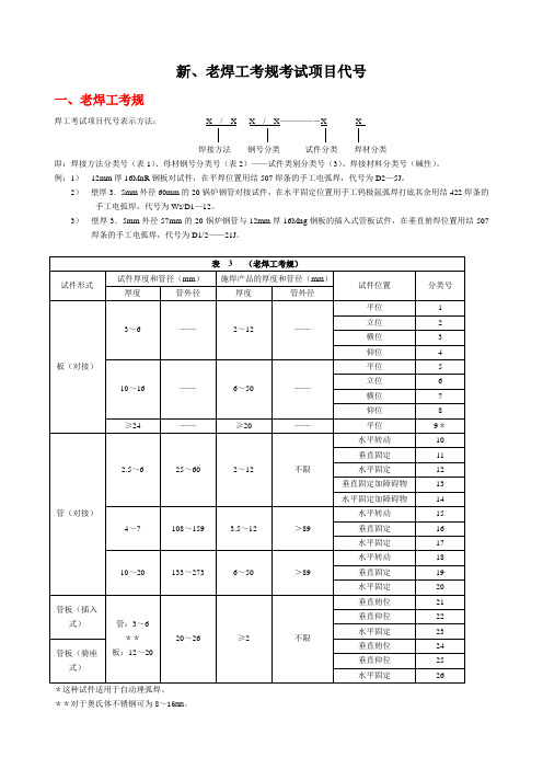
新、老焊工考规考试项目代号一、老焊工考规焊工考试项目代号表示方法:X / X X / X————―X X焊接方法钢号分类试件分类焊材分类即:焊接方法分类号(表1)、母材钢号分类号(表2)——试件类别分类号(3)、焊接材料分类号(碱性)。
例:1)12mm厚16MnR钢板对试件,在平焊位置用结507焊条的手工电弧焊,代号为D2—5J。
2)壁厚3.5mm外径60mm的20锅炉钢管对接试件,在水平固定位置用手工钨极氩弧焊打底其余用结422焊条的手工电弧焊,代号为Ws/D1—12。
3)壁厚3.5mm外径57mm的20锅炉钢管与12mm厚16Mng钢板的插入式管板试件,在垂直俯焊位置用结507焊条的手工电弧焊,代号为D1/2——21J。
*这种试件适用于自动埋弧焊。
**对于奥氏体不锈钢可为8~16mm。
注:焊工合格项目允许施焊的板厚或管外径查表3施焊产品的厚度和管径。
二、新焊工考规1、手工焊焊工考试项目代号表示方法为:①—②—③—④/⑤—⑥—⑦,其中:①焊接方法代号(见表1),耐蚀堆焊加:(N及试件母材厚度)。
②试件钢号分类代号(见表3),有色金属材料按相应标准规定的代号。
异种钢号用X/X表示。
③试件形式代号(见表4),带衬垫代号加:(K)。
④试件焊缝金属厚度。
⑤试件外径。
⑥焊条类别代号(见表2)。
⑦焊接要素代号(见表5)。
考试中不出现某项时,则不填。
2、焊机操作工考试项目代号表示方法为:①—②—③,其中:①焊接方法代号(见表1),耐蚀堆焊加:(N及试件母材厚度)。
②试件形式代号(见表4),带衬垫代号加:(K)。
③焊接要素代号(见表5),存在两中以上要素时,用“/”分开。
考试中不出现该项时,则不填。
3、项目代号举例:1)厚度为12mm的16MnR钢板对接焊缝平焊试件带衬垫,使用结507焊条手工焊,试件全焊透,项目代号为:SMAW—Ⅱ—1G(K)—12—F3J。
2)厚为8mm、外径为60mm的20g钢管对接焊缝水平固定试件,背面不加衬垫,用手工钨极氩弧焊打底,填充金属为实芯焊丝,焊缝金属厚度为3mm,然后采用结422焊条手工填满坡口,项目代号为:GTAW—Ⅰ—5G—3/60—02 和SMAW—Ⅰ—5G(K)—5/60—F3J。
松下伺服设置
时间
位置控制切换
17
等级
18
磁迟滞
19 位置增益切换时间
20
模式
21
时间
速度控制切换
22
等级
23
磁迟滞
24
模式
25
时间
转矩控制切换
26
等级
27
磁迟滞
关联模式 详细 PSTF 页
○○○○ ○ ○ ○ ○ 4-4 ○○○○ ○ ○ ○ ○ 4-5 ○○○○ ○ — — ○ 4-6 ○——○ ○ — — ○ 4-7 ○——○ ○ — — ○ 4-8 ○——○ ○ ○ ○ ○ 4-9 ○○○○ ○○○○ ○ — — ○ 4-10 ○——○ ○○○○
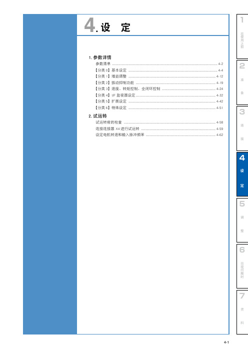
1. 参数详情
1
参数清单
参数号码 分类 号码
名 称
关联模式 详细 PSTF 页
参数号码 分类 号码
名 称
在
使
用
之
关联模式 详细
前
PSTF 页
00
SI1
○ ○ ○ ○ 4-32
11 立即停止时转矩设定
○○○○
01
SI2
02
SI3
○○○○ ○○○○
12 过载等级设置 13 过速度等级设置
○ ○ ○ ○ 4-45
○○○○
02 速度偏差过大设定
○———
27
过电压设定
○○○○
04 JOG 试机指令速度
○ — — ○ 4-51
28
零漂设定
29 模拟输入 3(AI3) 滤波器
○○○○ ○○○○
05 位置第 3 增益
有效时间
○——○
5
06
倍率
○○ ○
- 1、下载文档前请自行甄别文档内容的完整性,平台不提供额外的编辑、内容补充、找答案等附加服务。
- 2、"仅部分预览"的文档,不可在线预览部分如存在完整性等问题,可反馈申请退款(可完整预览的文档不适用该条件!)。
- 3、如文档侵犯您的权益,请联系客服反馈,我们会尽快为您处理(人工客服工作时间:9:00-18:30)。
4
3
2
1
FILE LIST
D
A3 BLOCK DIAGRAM
35
North Bridge DDR
THERMAL
05
POWER (IMVP4) FAN
03
BANIAS 24.5W
04
37
38
39
40
41
42
43
44
45
PSB
CPU Celeron/ Banias/ Dothan(400) Celeron/ Banias/ Dothan(400) Celeron/ Banias/ Dothan(400) Celeron/ Banias/ Dothan(400)/ Dothan(533) Celeron/ Banias/ Dothan(400)/ Dothan(533)
N C
01
Title : BLOCK DIAGRAM
ASUSTek COMPUTER INC. NB1 Size Custom Project Name
Engineer:
John Hung
Rev 2.4
36
A3N/A3L
Sheet
1
Date: Monday, November 15, 2004
3
1
of
AC_BAT_SYS
MAX1987 SUSC#. (3V_ON) LTC3728 (Regulator) 78L12 SUSB# +1.5VO (2A)
+V3.3SUS (5A) +12VO (0.15A) +V1.5S +V2.5 +V1.2S
C
+2.5VO (5A) SUSC# TPS5130 +5VAO +1.2VO (2A) SUSB# SUSB# SUSB# +V2.5 +V1.25S (2A) CM8562 (Regulator) SUSC# +2.5VO MIC37101-1.8 +1.8VO LDO +1.05VO (1A)
LVDS LCD
12
DDR TERMINATION MCHM MONTARA -GM 3.8W
06 07 08 09 11
A3N
C
855GM 852GM
266 266
A3L
A3Ne/A6Ne 855GME 333 852GME 333 A3Le 852GMV 266
RGB CRT
13
DDR
10
DUAL DDR SODIMM
1
Date: Monday, November 15, 2004
2
of
55
5
4
3
2
1
CPU Pin A1 need to be enlarged(M)
7 H_A#[16:3] U31B H_A#16 H_A#15 H_A#14 H_A#13 H_A#12 H_A#11 H_A#10 H_A#9 H_A#8 H_A#7 H_A#6 H_A#5 H_A#4 H_A#3 H_REQ#4 H_REQ#3 H_REQ#2 H_REQ#1 H_REQ#0 AA2 Y3 AA3 U1 Y1 Y4 W2 T4 W1 V2 R3 V3 U4 P4 U3 T1 P1 T2 P3 R2 A[16]# A[15]# A[14]# A[13]# A[12]# A[11]# A[10]# A[9]# A[8]# A[7]# A[6]# A[5]# A[4]# A[3]# ADSTB[0]# REQ[4]# REQ[3]# REQ[2]# REQ[1]# REQ[0]# ADDRESS GROUP 0 ADS# PRDY# PREQ# BNR# BPRI# DBR# N2 A10 B10 L1 J3 A7 1 T107TPC28b H_PRDY# H_PREQ# H_ADS# 7 U31A
H_D#[63:0] 7
DATA GROUP 0
2
H_BNR# H_BPRI#
7 7
D
DATA GROUP
COMMON CLOCK -> L6 WIDTH: 5 mils SPACE >= 1:2 GROUP SPACE >=1:5 LENGTH: 1" - 6.5"(OPT: 4"+/-0.5") Breakout Length:<=200 mil (#0011)
7
H_ADSTB#0
DEFER# DRDY# DBSY#
L4 H2 M2
H_DEFER# 7 H_DRDY# 7 H_DBSY# 7 7 H_DINV#0 7 H_DSTBN#0 7 H_DSTBP#0
H_D#15 H_D#14 H_D#13 H_D#12 H_D#11 H_D#10 H_D#9 H_D#8 H_D#7 H_D#6 H_D#5 H_D#4 H_D#3 H_D#2 H_D#1 H_D#0
24
USB 2.0 USB X4
34
KBC
26 27
SIO
28
SIR
Function Key
USB X2 for CCD & WLAN
12
PRINTER PORT
28SSIDຫໍສະໝຸດ SVID LAN:1045/1043 MDC:1826/1043 CardBUS:1894/1043 1394:1897/1043
SUSB#
+V1.5S
+VCCP
(1A)
B
PIC + TL494 (Charge)
FDS6679
A
W W W
+V3.3SUS
5
C .
CM2855 (LDO) +5VAO
4
FD6JK3TP
+3VALWAYS_M MIC5223MB (Regulator)
I H
BAT A/D_VIN +V1.5SUS +5VALWAYS
CONTROL
7
H_REQ#[4:0]
BR0#
N4 A4 B5 J2
H_BR0# H_IERR#
H_BR0# 2 R271 1 56Ohm H_INIT#
7
+VCCP
IERR# INIT#
7
H_A#[31:17]
ADDRESS GROUP 1
ADDR GROUP 0 -> L6 ADDR GROUP 1 -> L6 SPACE >= 1:2 STROBE SPACE >=1:3 GROUP SPACE >=1:5
2
01_BLOCK DIAGRAM 02_POWER DIAGRAM 03_CPU-BANIAS(HOST) 04_CPU-BANIAS(PWR) 05_THERMAL D 06_NB-MCHM(DDR) 07_NB-MCHM(HOST) 08_NB-MCHM(VGA) 09_NB-MCHM(PWR) 10_DUAL DDR SODIMM 11_DDR TERMINATION 12_LVDS & BACKLIGHT 13_CRT CONNECTOR 14_ICH4-M(HUB_PCI) 15_ICH4-M(H_U_IDE_PM) 16_ICH4-M(PWR) 17_ICH4-M_PULLUP 18_CLOCK-ICS950815 19_LAN-RTL8100CL 20_MINIPCI C 21_CB1394-R5C593(1) 22_CB1394-R5C593(2) 23_PCMCIA SOCKET 24_IDE-HD 25_IDE-ODD 26_KBC-M38857 27_SIO-ITE7805 28_IR&LPT_PORT 29_DISCHARGE CIRCUIT 30_CODEC-ALC650 31_AUDIO AMP 32_MIC 33_MDC&RJ45&RJ11 34_USB 35_FAN&Audio DJ 36_FUNCTION KEY B 37_PWR & RESET SEQ 38_VCORE 39_1.25V&1.8V 40_2.5V&1.5V&1.35V&1.05V 41_SYSTEM 42_LOAD SWITCH 43_CHARGER 44_PIC16C54 45_BATLOW/SD# 46_SCREW HOLE & M/B SETTING 47_REVISION(1) 55_Power Net Reference 48_REVISION(2) 49_REVISION(3) 50_REVISION(4) 51_BLOCK DIAGRAM 5E A 52_BLOCK DIAGRAM 7H 53_Part Reference 1 54_Part Reference 2
+5VLCM LM4040BIM +2.5VREF (500uA) (Regulator)
A
Title : POWER DIAGRAM
ASUSTek COMPUTER INC. NB1 Size Custom
2
Engineer:
Adams Lin
Rev 2.4
Project Name
A3N/A3L
Sheet
HUB CLOCK GEN
31 18 33
B
AUDIO AMP & MIC
32 30
AC'97 CODEC
AC97
MDC
1394 Card Reader
22
1394 CARDBUS
21 22
A
Discharge circuit
29
W W W
PCMCIA
23
20
