CMS2000硬件说明书
网络视频集中管理软件(CMS)使用说明书

在权限控制下,用户可以通过系统客户端对每个监控点方便地进行控制和设置,系统还集成了电 子地图功能。
1.2.11 集成度高。
系统集成了其它相关信息,如报警信息、语音信息等。 1.2.12 可靠性高。
第五章 系统设置........................................................................................................................... 16 5.1 监控点设置 .......................................................................................................................... 16 5.2 客户端配置 .......................................................................................................................... 20 5.3 设备配置 .............................................................................................................................. 24 5.4 用户管理 .............................................................................................................................. 36 5.5 客户端日志 .......................................................................................................................... 37
2000版微机监测终端安装及配置说明
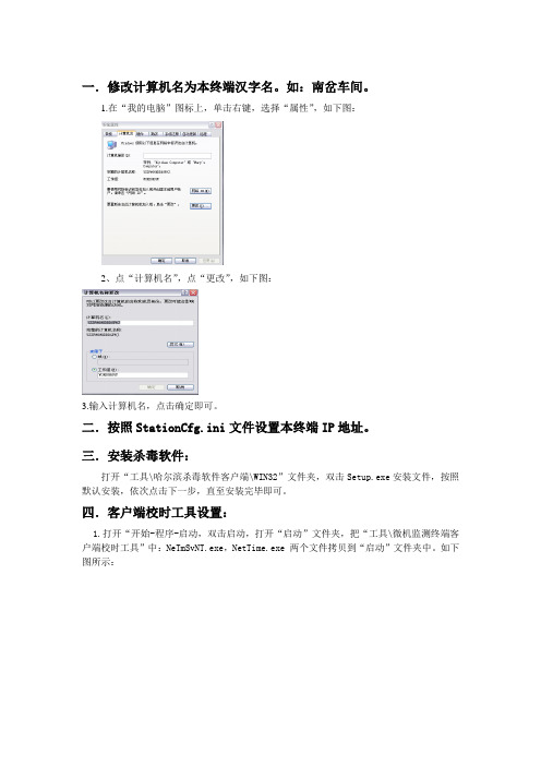
一.修改计算机名为本终端汉字名。
如:南岔车间。
1.在“我的电脑”图标上,单击右键,选择“属性”,如下图:2、点“计算机名”,点“更改”,如下图:3.输入计算机名,点击确定即可。
二.按照StationCfg.ini文件设置本终端IP地址。
三.安装杀毒软件:打开“工具\哈尔滨杀毒软件客户端\WIN32”文件夹,双击Setup.exe安装文件,按照默认安装,依次点击下一步,直至安装完毕即可。
四.客户端校时工具设置:1.打开“开始-程序-启动,双击启动,打开“启动”文件夹,把“工具\微机监测终端客户端校时工具”中:NeTmSvNT.exe,NetTime.exe 两个文件拷贝到“启动”文件夹中。
如下图所示:2.先运行一次NeTmSvNT.exe ,然后双击NetTime.exe ,在任务栏右下角,单击右键,点击设置(properties )校时软件,点击“settings ”按钮,出现如下图所示:安装以上显示设置各项参数,点击OK 即可。
五、终端软件安装与配置。
1软件安装1)打开“2000版终端程序”文件夹,运行安装程序“全局V2.0.5.6_Client.exe”,如下图:2)依次点击下一步,出现下图:依次点击下一步安装完成,点击完成。
2数据布署1.打开“2000版微机监测数据布署”文件夹,把JSecurity.dat,security.dat,servercfg.ini三个文件拷贝到终端程序安装目录(E:\Client)下。
2.如C盘根目录下无syscfg.ini文件,把“2000版微机监测数据布署”文件夹中syscfg.ini文件拷贝到C盘根目录下。
3. 配置说明终端程序安装成功后,需要对终端程序的配置文件进行配置和修改,以保证终端程序能够正常运行,说明如下:1、在终端程序的安装目录中,按照(模板)servercfg.ini,修改制作终端程序的网络配置文件servercfg.ini:只需要修改[终端配置]段,[服务器配置]段不用修改。
CMS组态软件使用说明书

CMS 组态软件使用说明书
CMS 组态软件使用说明书 (Version 2.0)
湖北万洲电气集团有限公司
HUBEI WORLDWIDE ELECTRIC GROUP CO., LTD.
湖北万洲电气集团有限公司 湖北省襄阳市长征路 58 号 邮编:441001 电话:(0710)3405668
用户将程序安装完毕后,进入安装的目标文件夹,如 D:\CMS。可以看到如下图所列文件。 湖北万洲电气集团有限公司 湖北省襄阳市长征路 58 号 邮编:441001 电话:(0710)3405668
-3-
万洲电气
CMS 组态软件使用说明书
图 1.4 CMS 软件组成
主要文件说明如下: CMSHelp:帮助文件夹,CMS 软件的操作和说明文件放在 CMSHelp 文件夹中,说明文件为.html 格式,用户可直接进入 CMSHelp 文件夹中点击打开或在程序中的帮助菜单进入。 CMSlockMenu:安全管理文件夹,文件夹中存放系统锁定后允许运行的程序快捷菜单。 CMSUILibrary:图形库文件夹,编辑好的图形库放在该文件夹。 DBRealTime:数据库文件夹,运行数据存储在该文件夹。 PlugIn:插件文件夹,CMS 扩展的插件模块放在该文件夹。 Protocols:通讯协议文件夹,监控软件所使用的通讯协议模块放在该文件夹。 CMS.exe:主监控程序。 CMSLock.exe:系统锁定程序,该程序运行后,将接管系统操作桌面,不能运行无关程序。 CMSReport.exe:报表程序,用于报表的设计和编辑。 CMSUser.exe:用户管理程序,用于管理操作用户的管理和操作权限。 Index.cmsui:画面程序,用于存放设计编辑的监控画面。 CurveView.exe:录波分析软件,可将录波数据和报表数据以波形或曲线形式显示。 default.cmscfg:用于存放通讯配置。 SelectCurve.exe:录波选择软件,使用该软件选择录取的波形文件。 SpeechAlert.exe:语音报警程序,中文语音报警。 BeepStart.exe:声音报警程序,可使用计算机自带轰鸣器报警。 2.4. CMS 软件的运行 CMS 组态软件安装完毕后,在桌面建立快捷方式,可选择 CMS 组态软件文件点击运行,也 可以选择锁定系统并运行 CMS 全部模块。区别是点击后者同时锁定并接管操作系统,用户不能 运行其它无关程序。 湖北万洲电气集团有限公司 湖北省襄阳市长征路 58 号 邮编:441001 电话:(0710)3405668
CMS手册系统说明书

CMS Manual System Department of Health &Human Services (DHHS) Pub 100-20 One-Time Notification Centers for Medicare &Medicaid Services (CMS) Transmittal 2054Date: April 13, 2018Change Request 10607 SUBJECT: Change in Type of Service (TOS) for Current Procedural Terminology (CPT) Code 77067I. SUMMARY OF CHANGES: This Change Request (CR) updates the TOS for CPT code 77067.EFFECTIVE DATE: January 1, 2017*Unless otherwise specified, the effective date is the date of service.IMPLEMENTATION DATE: July 2, 2018Disclaimer for manual changes only: The revision date and transmittal number apply only to red italicized material. Any other material was previously published and remains unchanged. However, if this revision contains a table of contents, you will receive the new/revised information only, and not the entire table of contents.II. CHANGES IN MANUAL INSTRUCTIONS: (N/A if manual is not updated)R=REVISED, N=NEW, D=DELETED-Only One Per Row.R/N/D CHAPTER / SECTION / SUBSECTION / TITLEN/A N/AIII. FUNDING:For Medicare Administrative Contractors (MACs):The Medicare Administrative Contractor is hereby advised that this constitutes technical direction as defined in your contract. CMS does not construe this as a change to the MAC Statement of Work. The contractor is not obligated to incur costs in excess of the amounts allotted in your contract unless and until specifically authorized by the Contracting Officer. If the contractor considers anything provided, as described above, to be outside the current scope of work, the contractor shall withhold performance on the part(s) in question and immediately notify the Contracting Officer, in writing or by e-mail, and request formal directions regarding continued performance requirements.IV. ATTACHMENTS:One Time NotificationAttachment - One-Time NotificationPub. 100-20 Transmittal: 2054 Date: April 13, 2018 Change Request: 10607 SUBJECT: Change in Type of Service (TOS) for Current Procedural Terminology (CPT) Code 77067 EFFECTIVE DATE: January 1, 2017*Unless otherwise specified, the effective date is the date of service.IMPLEMENTATION DATE: July 2, 2018I. GENERAL INFORMATIONA. Background: CR 10181 was issued to the public by the Centers for Medicare & Medicaid Services (CMS) on November 21, 2017. CR 10181, in part, instructed the claims processing system maintainers and contractors to implement CPT code 77067 in place of the healthcare common procedure coding system screening mammography code G0202, effective for claims with dates of service on or after January 1, 2018. Contractors were instructed to apply the same payment methodologies and editing as applicable for CPT code 77067 as they did for G0202. As part of the instruction to apply the same editing, the TOS coding for the 77067 should have remained, as it was for G0202, with a “1” (Medical Care) indicator. Correcting the TOS code for 77067 allows the screening mammography claims to be billed without referring physician information on the claim, which is consistent with Medicare’s coverage policy for screening mammograms (see 100-04 – Claims Processing Manual, Chapter 18 – Preventive and Screening Services, Section 20.)B. Policy: This instruction corrects the TOS indicator assigned to CPT code 77067 – Screening Mammography. Effective for claims with dates of service on or after January 1, 2017 the TOS indicator shall be updated to reflect "1" instead of "4" to allow for proper claim submission and adjudication.II. BUSINESS REQUIREMENTS TABLE"Shall" denotes a mandatory requirement, and "should" denotes an optional requirement.Number Requirement ResponsibilityA/B MAC DMEMACShared-SystemMaintainersOtherA B HHH FISSMCSVMSCWF10607.1 CWF shall update the Type Of Service (TOS)indicator for CPT code 77067 – ScreeningMammography from “4” to “1”.X10607.2 CWF shall ensure that the TOS indicator change forCPT 77067 – Screening Mammography is applicableto all claims (including adjustments) with dates ofservice on or after January 1, 2017.X10607.3 Effective January 1, 2017, contractors shall use Typeof Service code '1' for CPT code 77067 – ScreeningMammography.XNumber Requirement ResponsibilityA/B MAC DMEMACShared-SystemMaintainersOtherA B HHH FISSMCSVMSCWF10607.4 As necessary, contractors shall automaticallyreprocess previously adjudicated screeningmammography claims received with CPT - 77067with a TOS code of “4” with dates of service on andafter January 1, 2018 and through July 2, 2018 whenthe claim was denied because there was no referringprovider information.X10607.5 Contractors shall reprocess screening mammographyclaims with dates of service between January 1, 2018and July 2, 2018, which cannot be automaticallyreprocessed only if brought to your attention.XIII. PROVIDER EDUCATION TABLENumber Requirement ResponsibilityA/B MAC DMEMACCEDIA B HHH 10607.6 MLN Article: A provider education article related to this instruction will beavailable at /Outreach-and-Education/Medicare-Learning-Network-MLN/MLNMattersArticles/ shortly after the CR is released. You willreceive notification of the article release via the established "MLN Matters"listserv. Contractors shall post this article, or a direct link to this article, on theirWeb sites and include information about it in a listserv message within 5business days after receipt of the notification from CMS announcing theavailability of the article. In addition, the provider education article shall beincluded in the contractor's next regularly scheduled bulletin. Contractors arefree to supplement MLN Matters articles with localized information that wouldbenefit their provider community in billing and administering the Medicareprogram correctly.XIV. SUPPORTING INFORMATIONSection A: Recommendations and supporting information associated with listed requirements: N/A "Should" denotes a recommendation.X-RefRecommendations or other supporting information:RequirementNumberSection B: All other recommendations and supporting information: N/AV. CONTACTSPre-Implementation Contact(s): TeiraCanty,*******************.govPost-Implementation Contact(s): Contact your Contracting Officer's Representative (COR).VI. FUNDINGSection A: For Medicare Administrative Contractors (MACs):The Medicare Administrative Contractor is hereby advised that this constitutes technical direction as defined in your contract. CMS does not construe this as a change to the MAC Statement of Work. The contractor is not obligated to incur costs in excess of the amounts allotted in your contract unless and until specifically authorized by the Contracting Officer. If the contractor considers anything provided, as described above, to be outside the current scope of work, the contractor shall withhold performance on the part(s) in question and immediately notify the Contracting Officer, in writing or by e-mail, and request formal directions regarding continued performance requirements.ATTACHMENTS: 0。
DMC2000硬件手册

DMC2000硬件手册深圳雷赛DMC2000硬件手册.版本1.2第一章概述1.1 产品简介DMC2000系列是基于PCI总线的高性能运动控制卡,可控制多达4个步进或伺服电机。
此系列具有即插即用、最高2.4MHZ脉冲频率、S曲线减振功能、编码器反馈、Z信号精密找零、随时变速等高级功能。
位置指令可用单路脉冲(脉冲+方向)或双路脉冲(CW脉冲+CCW脉冲)方式输出,可以是差分式,也可以是单端式。
如用于伺服控制时,每轴提供了报警(ALM),定位完成(INP),误差清除(OUT3,4,5,6),伺服开启(OUT1,2,7,8)和已准备(INPUT)等五个信号,使用户的接口和编程工作大大简化。
DMC2200可控制1至2个电机作独立或插补运动,DMC2400可控制多达4个电机。
DMC2000系列比ISA总线的DMC200功能更加强大,硬件接口上有一定的相似性,软件指令方面有一定程度的兼容性。
本产品配有WIN95/98/NT/2000下的动态链接库,方便客户编写自己的应用软件,同时提供MOTION2000调试示范软件,可演示此卡功能,方便客户测试控制卡以及电机驱动系统。
1.2 产品特点32位PCI总线,即插即用两轴圆弧和直线插补功能,3轴或4轴直线插补最大输出脉冲频率2.4MPPS 加/减速时间可任意编程脉冲输出模式:脉冲/方向、正向/反向可选T/S型速度曲线可选,非对称加减速最多4轴脉冲和方向输出,控制步进和伺服电机用于增量编码器反馈的28位上/下计数器多轴连续起动/停止可编程中断源全部I/O光隔离,耐2500VRMS电压运动中可改变速度每轴提供原点、索引信号、正负限位开关专用接口手动脉冲输入接口最多支持一个系统12块卡同时工作 Microsoft Windows 应用开发软件, MOTION2000 调试软件每轴具编码器计数和反馈功能DMC2000库和实用程序及Windows 95/98/ NT /2000 DLL1.3 技术指标性能:□控制轴数: 2轴 (DMC2200), 4轴 (DMC2400)□内部参考时钟: 9.8304MHZ□最大脉冲输出频率: 2.4MHZ线性、梯形或S曲线速度驱动方式□位置脉冲设置范围: 0--268,435,455 个脉冲(28位)□斜坡下降设置范围:0--16,777,215□加/减速设置范围: 1--65535(16位)□上/下计数器计数范围:0--268,435,455(28位)或-134217728--+134217727□脉冲速率设置: 0--2.4MPPSI/O信号:□DMC2400的通用I/O口一般是4进4出,软件设置后最多可达12进8出(8个SD输入,4个INPUT输入);DMC2200的通用I/O口一般是2进6出,软件设置后最多可达6进6出(4个SD输入,2个INPUT输入,6个通用OUT输出)。
CMS软件使用说明书
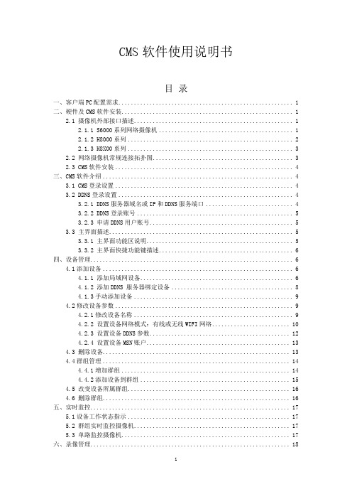
CMS软件使用说明书目录一、客户端PC配置需求 (1)二、硬件及CMS软件安装 (1)2.1 摄像机外部接口描述 (1)2.1.1 S6000系列网络摄像机 (1)2.1.2 H8000系列 (2)2.1.3 H8X00系列 (3)2.2 网络摄像机常规连接拓扑图 (3)2.3 CMS软件安装 (4)三、CMS软件介绍 (4)3.1 CMS登录设置 (4)3.2 DDNS登录设置 (4)3.2.1 DDNS服务器域名或IP和DDNS服务端口 (4)3.2.2 DDNS登录账号 (5)3.2.3 申请DDNS用户账号 (5)3.3 主界面描述 (5)3.3.1 主界面功能区说明 (5)3.3.2 主界面快捷功能键描述 (6)四、设备管理 (6)4.1添加设备 (6)4.1.1 添加局域网设备 (6)4.1.2 添加DDNS 服务器绑定设备 (8)4.1.3手动添加设备 (9)4.2修改设备参数 (9)4.2.1修改设备名称 (9)4.2.2 设置设备网络模式:有线或无线WIFI网络 (10)4.2.3 设置设备DDNS参数 (12)4.2.4 设置设备MSN账户 (13)4.3 删除设备 (13)4.4群组管理 (14)4.4.1增加群组 (14)4.4.2添加设备到群组 (15)4.5 改变设备所属群组 (16)4.6 删除群组 (16)五、实时监控 (17)5.1设备工作状态指示 (17)5.2 群组实时监控摄像机 (17)5.3 单路监控摄像机 (17)六、录像管理 (18)6.1设置定时录像或报警录像时段 (18)6.2 手动录像 (19)6.2.1组内设备同时录像 (19)6.2.2任意设备录像 (20)6.3录像存储管理 (20)七、报警联动 (21)7.1 报警参数设置 (21)7.2 启用报警联动显示参数设置 (22)7.3 实时显示报警日志及报警图像 (23)7.4 浏览报警日志并查看报警录像 (23)八、用户管理 (24)8.1 CMS软件用户管理 (24)8.2 设备访问用户管理 (25)九、录像播放 (26)9.1进入同步播放器 (26)9.2 按群组方式选择播放通道 (27)9.3 随机选择播放通道 (27)9.4 选择播放日期 (28)9.5 选择播放时间点开始多通道同步播放 (28)十、云台控制 (29)10.1云台参数设置 (30)10.2 云台控制 (30)十一、无线WIFI监控 (31)11.1路由器相关设置 (31)11.2启动设备WIFI功能 (32)十二、系统扩展功能 (33)12.1 对讲功能 (33)12.2 拍照功能 (34)12.3 视频颜色参数调节 (35)一、客户端PC配置需求软件运行最低PC配置要求如下:处理器: Pentium Ⅳ 2.8G或以上;内存: 1G以上;显卡: 256M以上;网卡:10M或以上;操作系统:Windows XP、Windows 7。
CMS安装配置手册

安川西门子自动设备有限公司目录一、简介 (3)二、CMS的运行环境 (3)三、程序安装 (3)四、CMS程序的设置 (4)4.1 CMS主机名的设定 (5)4.2 CMS 主机IP的设定 (6)4.3 CMS PLC IP 设定 (7)4.4 CMS 画面 (7)4.4.1 首次启动 (8)五、相关软件的安装 (10)5.1 CP717、CimScope的安装 (10)5.2 CP717的配置 (11)5.3 CP717的配置 (13)5.4 CP717-CMS通讯设定 (18)六、CMS程序与PLC硬件的连通 (19)七、CMS程序的PLC跳转功能 (21)7.1 UMN文件的生成 (21)7.2 数据库配置 (24)7.3 CMS程序和PLC间的跳转 (24)八、CMS安装中需注意的问题 (26)九、常见问题 (26)一、简介CMS系统全称起重机监控系统(Crane Monitoring System),主要用于起重机的实时监视、故障分析处理、数据采集、运行维护、生产统计和整车使用状况分析,对于统计和分析的结果以报表的方式输出,能够有效的帮助维修人员监控和维护起重机。
CMS程序安装包括程序安装和CP717、CimScope软件设置两个部分。
二、CMS的运行环境CMS程序的运行环境如下表所示:三、程序安装CMS系统安装主要步骤:1 .检查硬件:UPS、电源、鼠标键盘、显示器、网络2 . 检查操作系统CMS计算机名(名称不要超过16个字符)、CMSIP设定、CMSPLCIP设定、驱动安装、显示设置、硬盘空间以及分区情况等3. 检查软件环境Office(Word,Xls,Access);CP717 V4.39以下;CIMSCOPE V0.41C ;主PLC程序;CMS PLC程序4 . 将CMS程序的安装光盘放入光驱内运行,点击项目文件夹中的Setup图标起动安装程序(如下图中被鼠标点中的图标所示)。
CMS多路集中管理软件说明书

CMS多路集中管理软件说明书第一章安装说明1.1 运行环境要求1.1.1 硬件:CPU P4/2.0G显卡必须支持硬件缩放(如ATI、TNT2 PRO)(建议使用ATI9800及以上显卡,双通道)显存128M以上/128bit注:如果解的画面很多,内存、显卡、CPU最好配置好一点。
网卡:100/1000M1.1.2 软件:本软件可支持Vista/WinXp/Win2000/Win2003/Win2007, 建议不在Windows 98下运行。
装软件前请关闭计算机中所有正在启用的杀毒软件和防火墙等以便控制中心运行程序的正确和完全写入,否则可能会出现无法搜索到设备。
1.2 安装步骤1)在光盘中找到并双击“General_CMS_Chn_V3.0.8.2.T.20120528.exe”文件,弹出如下图所示对话框。
2)单击“Next”按钮,弹出如下图所示对话框。
3)输入用户信息,单击“Next”按钮,弹出如下图所示对话框。
4)按“Change”键,选择安装路径,系统默认文件夹为“C:\Program Files\CMS”,单击“Next”按钮,选择创建类型,如下图所示。
5)单击“Next”按钮,开始安装CMS,弹出如下图所示对话框6)单击“Next“按钮进行安装。
如下图7)单击“Finish”键完成安装。
此时,桌面将出现如下图标软件初始密码空第二章添加监控点监控点管理2.1单击按钮添加区域,如图1所示:图1 添加区域在这里可以添加自己要监视的区域,方便管理各个不同区的不同监控点,例:这里输入“滨江”确定则出现图2界面:图2 添加区域2.2单击按钮添加设备,界面如下图3 添加设备点击“IP搜索”,可以搜索出当前局域网内所接的设备,选中IP地址,“添加设备”。
图4 问题:子网的不匹配“编辑设备”:出厂默认的IP地址:192.168.1.10,子网掩码:255.255.255.0,默认网关:192.168.1.1http端口:81 (IE浏览端口)TCP端口:34567 (CMS管理软件端口)手机端口:34599 (手机观看端口)修改IP地址/默认网关与PC同步图5 修改内网IP/网关重新点击“搜索IP”,选中IP地址,“添加设备”。
CMS产品说明手册

培训材料CMS产品说明手册文档信息⏹文档位置文档存放在文档服务器:⏹文档修订历史⏹分发本文档已被分发到如下人员:⏹相关文档及参考资料1.1栏目维护 (3)1.2内容维护 (5)1.2.1内容维护 (5)1.2.2评论维护 (8)1.3内容审批 (9)1.4投票维护 (12)1.5站点管理 (14)1.6公告维护 (15)1.7功能节点维护 (16)1.8专题维护 (17)1.8.1专题维护 (17)1.8.2专题文章管理 (18)1.9资源维护 (20)1.10回收站 (20)1.11模板管理 (22)1.11.1模板维护 (22)1.11.2重载模板 (24)1.12用户管理 (25)1.12.1企业用户管理 (25)1.12.2VIP用户管理 (26)1.12.3普通用户管理 (26)1.13索引管理 (27)1.13.1文章索引管理 (27)1.13.2企业用户索引管理 (27)1.14加盟企业图片维护 (27)1.15数据统计 (29)1.15.1 文章统计 (29)1.15.2 企业用户统计 (30)1.15.3 需求统计 (30)1.1栏目维护功能概述:本模块完成栏目的维护,包括完成“生成本栏目下静态页面”、“新增下级栏目”、“删除当前栏目”等维护,并完成保存和修改功能。
本模块完成栏目维护,包括完成“栏目大类”,“栏目小类”的维护,栏目大类和小类的增加,并完成保存功能,以及可以实现对栏目的删除以及新增下级栏目的功能。
操作界面:栏目显示区域:栏目显示编辑区域:功能用途:根据网站内容管理系统(CMS)定义的系统授权规则,“网站管理员”可以定义网站的顶级栏目,而普通用户只能定义其所能管理栏目的子栏目。
判断用户是否有拥有操作权限的栏目;1.创建子栏目:用户被授权可以建立“子栏目”。
用户可以修改的栏目属性包括栏目的基本属性和管理属性。
2.删除子栏目:点击栏目列表中“删除”列按钮,可以删除某个栏目,能够删除的栏目必须不在包含任何子栏目,包含子栏目的栏目不能被删除。
2000系列设备初学者指南说明书
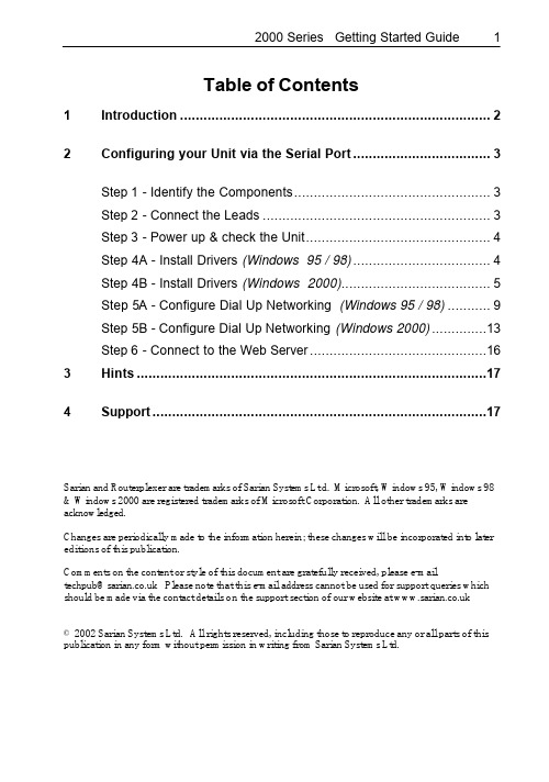
Table of Contents1Introduction (2)2Configuring your Unit via the Serial Port (3)Step 1 - Identify the Components (3)Step 2 - Connect the Leads (3)Step 3 - Power up & check the Unit (4)Step 4A - Install Drivers (Windows 95 / 98) (4)Step 4B - Install Drivers (Windows 2000) (5)Step 5A - Configure Dial Up Networking (Windows 95 / 98) (9)Step 5B - Configure Dial Up Networking (Windows 2000) (13)Step 6 - Connect to the Web Server (16)3Hints (17)4Support (17)Sarian and Routerplexer are trademarks of Sarian Systems Lt d. Microsoft, Windows 95, Windows 98 & Windows 2000 are registered trademarks of Microsoft Corporation. All other trademarks are acknowledged.Changes are periodically made to the information herein; these changes will be incorporated into later editions of this publication.Comments on the content or style of this document are gratefully received, please e-mail*****************.ukPleasenotethatthise-mailaddresscannotbeusedforsupportquerieswhich should be made via the contact details on the support section of our website at © 2002 Sarian Systems Ltd. All rights reserved, including those to reproduce any or all parts of this publication in any form without permission in writing from Sarian Systems Ltd.1 IntroductionThank you for purchasing a Sarian Systems 2000 Series Communications device.This “Getting Started” guide will help you to make initial contact with your unit in order to set the configurable options. The vast majority of applications, however, will need very little configuration to operate correctly.Your unit has a wide range of advanced features ranging from remote management, protocol conversion and diagnostics to in-built protocol analyzers.To understand how to use these features, you should carefully read the attached documentation which is supplied either on CD-ROM or paper. The CD-ROM contains a full User Guide in Adobe™ Acrobat™ format and we recommend that you read this thoroughly in order to get the best out of your unit.IMPORTANT : Throughout this guide we will use the IR2140 Router as an example, however the instructions apply equally to any Terminal Adaptor, Multiplexer or other specialist device in the Sarian 2000 series.There are four ways you can send configuration commands to your unit :• Using a Web Browser to access pages on the built in Web Server• Command line sessions via Telnet• Sending a specific configuration file using FTP• By sending ‘AT’ type commands to the serial portUsing a web browser such as Netscape Navigator™ or Internet Explorer™ is simplest and easiest to understand method and is the one explained in this booklet. The other methods are described in full in the User Guide on the CD-ROM.To configure your unit via the built in web server, you will first need to establish a PPP serial connection between your unit and a local computer via the supplied serial cable, then use a web browser to access the configuration pages where you can make the necessary configuration changes.Note that steps 4 and 5 are different depending on your operating system.2 Configuring your unitStep 1 - Identify the ComponentsIn the packaging you should find the following items :• One System Unit• Serial Modem cable for configuration• One ISDN patch lead (ISDN capable units only)• One Plug Top Power supply• Serial adapter leads (RJ45 to 9 or 25 Way D Type) (optional)• One CD-ROM containing full documentation• This “Getting Started Guide”Step 2 - Connect the LeadsUsing the supplied serial cable connect a PC or laptop to the 25 way socket marked ‘PORT 0’. Next, connect one end of the ISDN patch lead into the Router socket marked ISDN BRI and the other end into the ISDN network socket installed by your network provider. Be careful not to accidentally plug the ISDN circuit into a serial port !Finally, plug the connector of the power supply into the socket marked 12V DC and plug the adapter into a convenient mains power outlet.The above picture is the rear panel of an IR2140 Router. Other types of unit, such as theIR2110 and GR2130 routers may have slightly different back panel layouts, however, ISDN BRI, 12V DC and PORT 0 will still be clearly marked as above.The serial ports equipped with an RJ45 socket (PORT 2 & 3 in the photo above) require adaptor leads to connect them to your serial devices. These may optionally be supplied with your unit or you can make them up yourself according to the wiring diagram shown in the full User Guide on the CD-ROM.Step 3 - Power up & check the UnitWhen power is applied, the red ‘ON’ indicator will light on the front panel and the unit will self-test.All green lights on the front panel will flash rapidly and then go out. The ‘B2’ light will then flash alternately red and green to indicate self test in progress, then ex tinguish.If you have connected the unit to an ISDN line in Step 2, it will then try to establish a connection to the local exchange via the D Channel. If it succeeds, the ‘D’ indicator will come on and remain lit.If any other lights except the ‘ON’ and ‘D’ indicators remain on, the unit has a detected a fault and you should consult the full documentation for further guidance. DO NOT TRY TO ACCESS THE UNIT UNTIL THE SELF TEST IS COMPLETE.Now proceed to Step 4A for Windows 95/98 or Step 4B for Windows 2000.Step 4A - Install Drivers (Windows 95 / 98)Switch on your PC and from the Start Menu select START > SETTINGS > CONTROL PANEL> MODEMS and click on the Add button.Windows will advise that it will try to detect your modem. Since we are making a manual installation, ensure that the ‘Don’t detect my modem, I will select it from a list’ is checked and click Next >.You will be presented with a list of devices. Ignore these and click on Have Disk…You will now need to place the supplied CD-ROM in the drive. Browse to it until you locate the .inf file for your unit as below which is located in the /drivers/win95-98/ folder, then click on OK and then OK again. You will then be presented with a list of available drivers and you should select the appropriate Sarian 2000 Series variant to match your unit.You will then be asked to confirm which communications port you have connected the serial lead to as below :You should click Next > and the driver should install. You will then see a confirmation that the configuration is complete and you can click Finish.Now proceed to Step 5A – Configure Dial up Networking (Windows 95/ 98).Step 4B - Install Drivers (Windows 2000)From the Windows Start menu, select Settings > Control Panel then click on the Phone And Modem Options icon. Click on Modem Tab. The following dialogue will appear :Click Add.. then check “Don't detect my modem; I will select it from a list” as shown below, then click Next>You will see the following dialogue asking you to select the appropriate device. Click Have Disk…You will now need to insert the CD-ROM which came with your unit and browse to the folder /drivers/win2000 then select Sarian .inf file there. The following dialogue will appear :Select the appropriate modem (e.g. Sarian Systems IR2140 ISDN Router), then click Next>. Either select the individual communications port you wish to connect your Sarian unit to or select All PortsClick Next>.Answer Yes to the “digital signature not found” dialog box and then click Finish.Now proceed to Step 5B – Configure Dial up Networking (Windows 2000).Step 5A - Configure Dial Up Networking (Windows 95 / 98)From the windows desktop, double click on the ‘My Computer’ icon.. Click on ‘Dial-Up Networking then ‘M ake New Connection’.Type in ‘M y Sarian’or some other meaningful phrase and select‘Sarian Systems Series 2000’ so that the screen looks like the one below :Next, click on CONFIGURE… and ensure that the correct COM port (i.e. the one c onnected to PORT 0 of your unit) for your PC is selected on the General tab and that the maximum speed is selected as 115200. You screen will look as below :Now selec t the Connections tab and set the data format to 8 data bits, NO Parity and 1 stop bits like this :Click on OK to return to the Make New Connection dialogue and press Next>. Now type in 123 as the Telephone number and ensure the Area Code is blank, like this :When you have done this, click Next>.The next dialogue screen will confirm the completed connection. Press Finish to complete the configuration.Before attempting to connect, check the Dial-Up networking properties by right clicking the newly created connection and selecting Properties. On the General tab, make sure that‘Use area code and Dialing Properties’ is not checked.Now select the ‘Server Types’ tab and ensure that that all the boxes are unticked EXCEPT for TCP/IP as below :Finally, click OK to close the dialogue box. You have now configured the Dial Up Networking and now will use the connection you just made to dial up the unit through the serial cable. Click on the Dial Up Networking Connection you have just created and enter the User Name as ‘username’ and the Password as ‘password’ as shown belowClick the Connect button. You will see a series of status dialogues from Dialing … through Verifying User Name and Password … to Logging on to Network … then you should see the modem lights in the system tray (next to the clock):You now have a connection between your PC and the Sarian unit, you now need to connect to the web based user interface to configure the unit.Now proceed to Step 6– Connect to the Web Server.Step 5B - Configure Dial Up Networking (Windows 2000)From the Windows menu, select Settings then click on the Network and Dial-up Connections icon, then on Make New Connection. Click Next> to start the Network Connection Wizard.Select "Dial-up to private network" and click Next>. Then select ‘Modem - Sarian Systems (your com port)’ and click Next>. You will see the following dialogue :E nter 123 as the phone number and ensure that "Use dialing rules" is NOT checked. Click Next>.Decide whether to create this connection for all users of your PC or just yourself and click Next>.Give the connection a suitable name (e.g. “Sarian IR2140”) and then click Finish to create the new connection.Next, click on properties, and select the networking tab. You should have a dialogue like this:Ensure that the only component checked in the list is Internet Protocol (TCP/IP). Click the settings button and ensure that all of the PPP settings are un-checked. Now click the General tab. Select the “Sarian Multiplexer” and click Configure.Ensure the “Maximum speed (bps)” is set to 115200, ensure that the only check box on this page ticked is that for the “Enable Hardware flow control”. Click OK and click OK again. You will now be asked to dial the connection you just made. Enter "username" in the user name field. Enter "password" in the password field (case sensitive !). Check the “Save Password” box and click Dial.Your PC should now connect to the Sarian router and you should see the modem lights icon appear in the system tray, like this :Now proceed to Step 6 – Connect to the Web Server.Step 6 - Connect to the Web ServerStart a web browser on your PC (Netscape Navigator or Internet Explorer 5.0 or greater). Point your web browser at http://1.2.3.4. You will see a login prompt from the unit’s built in web server.Type in the default username which is ‘username’ and the default password which is‘password’, then click on Login.If everything is connected up properly, you will see the following configuration page :You can now go on to set the individual settings for your Sarian unit using the web based interface. Most of the settings are straightforward, but if you are in any doubt, check the full documentation which came with your unit or contact Sarian Systems at the address below.3 HintsThe above instructions assume that you already have Dial-Up Networking and TCP/IP installed on your computer. If you do not you should consult your Windows documentation on how to do this.If your unit has a LAN port, you can bypass the instructions in Section 2 about installing drivers and connect directly to the web server on the default IP address 192.168.0.99. Make sure that your PC is on the same sub-net.If you do not yet have a network installed, you can use a 10BaseT CROSSOVER cable to effect a one to one connection between your PC and the unit. Note that 2000 series units with a hub can use either a crossover cable or a standard LAN patch lead and the unit will autodetect the type.Remote connection. If you wish to connect to a remote Sarian 2000 unit, follow the installation guidelines given above, but substitute your own local ISDN Terminal Adaptor details. When asked for the number to dial, instead of ‘123’ type the full ISDN telephone number including the area code.4 SupportTips and guidance on the installation and use of your unit can be found on the Sarian Systems website at under the support section. New versions of the firmware for you unit may also be available for download from the website.If, despite reading the user documentation you still cannot get your unit to operate either :Call Sarian Systems Support Helpline on 01943 605055orSubmit an e-support request via orContact Sarian Systems atSarian Systems Ltd.Beacon HouseRiverside Business ParkLeeds RoadIlkleyW. YorksLS29 8JZFax : 01943 605056。
CMS_使用说明书(中文)
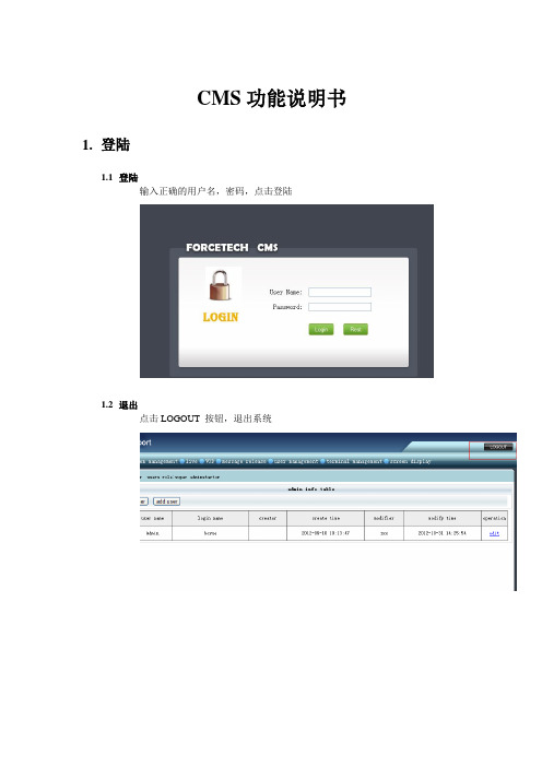
CMS功能说明书1.登陆1.1登陆输入正确的用户名,密码,点击登陆1.2退出点击LOGOUT 按钮,退出系统2.权限管理2.1管理员2.1.1增加输入正确的信息,点击提交,其中”admin authority” 在对应角色管理中的角色2.1.2删除勾选要删除的管理员,点击删除按钮2.1.3修改(1) 点击修改按钮(2) 修改完点击提交2.2角色管理2.2.1增加输入角色名,勾选要授予的权限,点击提交, 角色名不能跟已有的相同2.2.2删除勾选要删除的角色,点击删除按钮,如果角色已经授予给某一管理员,则无法删除, 若要删除必须先删除关联的管理员2.2.3修改(1) 点击修改按钮进入修改(2)点击提交保存修改的信息3.系统管理3.1服务器管理3.1.1增加服务器选择服务器类型,输入带星号的项,点击提交, 除了资源服务器,其他服务器只允许添加一台。
(1)资源服务器字段说明:输入服务器: 名任意字符服务器ID: 对应资源服务器提供的ID(2)CMS服务器字段说明:服务器名称:任意字符IP 地址:对应CMS服务器的IP地址端口:对应CMS服务器的端口Server id: 0(3)控制服务器字段说明:服务器名称:任意字符IP 地址:对应控制服务器的IP地址端口:9906Server ID: 0(4)P2P服务器字段说明:服务器名称:任意字符IP 地址:对应P2P服务器的IP地址端口:9907Server ID: 03.1.2删除服务器勾选要删除的服务器,点击删除, 此操作影响较大,将会导致客户端无法正常工作。
3.1.3修改服务器(1)点击修改按钮,进入修改(2) 输入正确的信息,点击提交, 具体填写的字段信息请参考添加的功能3.2日志管理3.2.1日志查询可以根据操作模糊查询,根据操作人查询,根据操作的时间段查询3.3数据库备份点击备份按钮,把整个数据库导出来。
4.直播4.1增加填写带星号的必填项,点击提交,其他项不用填写。
CMS使用说明书
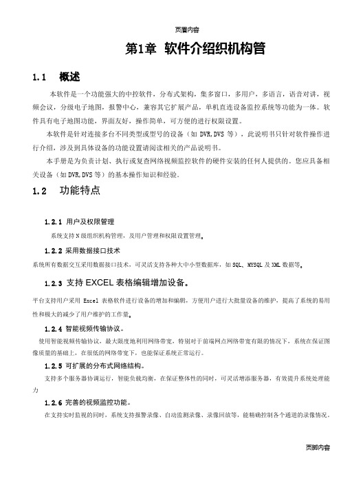
页眉内容第1章软件介绍织机构管1.1 概述本软件是一个功能强大的中控软件,分布式架构,集多窗口,多用户,多语言,语音对讲,视频会议,分级电子地图,报警中心,兼容其它扩展产品,单机直连设备监控系统等功能为一体。
软件具有电子地图功能,界面友好,操作简单,可方便的进行权限设置。
本软件是针对连接多台不同类型或型号的设备(如DVR,DVS等),此说明书只针对软件操作进行介绍,涉及到具体设备的功能设置请阅读相关的产品说明书。
本手册是为负责计划、执行或复查网络视频监控软件的硬件安装的任何人提供的。
您应具备相关设备(如DVR,DVS等)的基本操作知识和经验。
1.2 功能特点1.2.1用户及权限管理系统支持N级组织机构管理,及用户管理和权限设置管理。
1.2.2采用数据接口技术系统所有数据交互采用数据接口技术,可灵活支持各种大中小型数据库,如SQL、MYSQL及XML数据等。
1.2.3支持EXCEL表格编辑增加设备。
平台支持用户采用Excel表格软件进行设备的增加和编辑,方便用户进行大批量设备的维护,提高了系统的易用性和极大的减少了用户维护的工作量。
1.2.4智能视频传输协议。
使用智能视频传输协议,最大限度地利用网络带宽,特别对于前端网点网络带宽有限的情况下,系统在保证图像质量的基础上,在很低的网络带宽下,也能保证系统正常运行。
1.2.5可扩展的分布式网络结构。
支持多个服务器协调运行,智能负载均衡,在保证整体性的同时,可灵活增添服务器,有效提升系统处理能力1.2.6完善的视频监控功能。
在支持实时监视的同时,系统支持报警录像、自动监测录像、录像回放等,能精确控制各个通道的录像情况。
1.2.7动态调节解码缓冲。
实时监视时可灵活调节视频图像流畅性或实时性优先,流畅性讲求视频图像的流畅,实时性强调视频图像的实时,可满足不同用户的需求。
1.2.8采用货架技术,模块化开发,可灵活组装应用方案。
系统采用货架技术,分层及模块化开发,具有丰富的中件间服务,可以方便的进行各种应用方案的灵活组装。
SIPLUS CMS2000 Basic Unit V1.1 数据传输至PC的说明书
Service & SupportCover Sheet Transfer of Raw Data to a PCSIPLUS CMS2000 Basic Unit / V1.1 FAQ August 2012FAQ on SIPLUS CMS2000 Basic Unit / V1.1This article originates from the Service & Support Portal of Siemens AG, SectorIndustry, Industry Automation and Drive Technologies. The respective terms of useare applicable (/nutzungsbedingungen).This document can be directly downloaded via the following link:/WW/view/en/63926267QuestionHow can raw data recorded with SIPLUS CMS2000 be transferred from the deviceto a PC?AnswerThe answer to this question is described in the instructions and notes contained inthis document.Transfer of Raw Data to a PCFAQ on SIPLUS CMS2000 Basic Unit / V1.1Table of Contents1General (4)1.1What are raw data? (4)1.2How to access raw data? (4)2Copying via the Web Interface (5)3Data Transfer via FTP with the Help of WinSCP (6)3.1What is WinSCP? (6)3.2Manual data transfer via the user interface (6)3.3Automatic data transfer via WinSCP script (8)Transfer of Raw Data to a PCFAQ on SIPLUS CMS2000 Basic Unit / V1.11 General1.1 What are raw data?The SIPLUS CMS2000 condition monitoring system facilitates the recording andinternal saving of raw data in the form of WAV files. The term raw data refers todirect records pertaining to vibration inputs, analog inputs and speed. Up to fivechannels are thus written into every raw data file.The parameterization determines the specific channels for recording. A channel isrecorded when it is correctly configured (see operating instructions, chapter 8.13"Hardware configuration" menu, page 125 et seqq.).Raw data recording can be triggered by three events:▪when a parameterized limit exceeded▪ User command▪Digital input TRIGGERThe recording duration amounts to one minute after the start event.For further information on raw data recording, please refer to the operatinginstructions, chapter 8.8 "Raw data recording", page 53.1.2 How to access raw data?For the recorded raw data's further processing, the files can be transferred from theSIPLUS CMS2000 Basic Unit to a local computer.For this purpose, a TCP/IP connection has to be set up between the device andthe computer. Configuration of this Ethernet connection and possible safetyaspects for data transfer are not described in this article.For further software and hardware requirements regarding connection and webbrowser, please refer to the operating instructions, chapter 8.2, page 40.Two options are available for implementation of the copy process, which aredescribed in detail in the following chapters.▪Copying via the SIPLUS CMS2000 web interface▪Data transfer via FTP, e.g. with the WinSCP FTP client softwareTransfer of Raw Data to a PCFAQ on SIPLUS CMS2000 Basic Unit / V1.1Transfer of Raw Data to a PC2 Copying via the Web InterfaceThe recorded raw data can be manually copied to a local computer ("download") via the SIPLUS CMS2000 web interface. Such download is subject to two prerequisites:▪ A user has to be logged into the device ▪ The Basic Unit has to be in the stop stateThe download process can be started via the download site "Administration > Download". If the device comprises multiple raw data records, first select thedesired file in the drop-down menu and then click the link "Download selected file".Figure 1: Download via the web interfaceDepending on your browser's security settings, a dialog window opens in whichyou have to confirm the file's saving to your computer.Figure 2: Security query of the browserConfirm this security query with OK and select the desired storage location on your computer in the dialog window which opens next.FAQ on SIPLUS CMS2000 Basic Unit / V1.1Transfer of Raw Data to a PC3Data Transfer via FTP with the Help of WinSCP3.1 What is WinSCP?WinSCP is an open-source FTP client software which facilitates data exchange via the File Transfer Protocol (FTP). Besides FTP, WinSCP supports further protocol types such as SFTP and SCP. However, these are not supported by the SIPLUS CMS2000 Basic Unit V1.1. Data transfer can be implemented manually via a graphical user interface or automatically as command line call.WinSCP is available via /eng/download.php or as portable application via /apps/internet/winscp_portable .3.2 Manual data transfer via the user interfaceFollowing installation or copying, WinSCP is called up from the installation directoryvia the file "WinSCP.exe" or "WinSCPProtable.exe".WinSCP refers to the communication connection between the local PC and a remote device as session. Amongst others, a session contains all session parameters relevant for connection establishment.The following connection parameters have to be used for a session with the SIPLUS CMS2000 Basic Unit: Parameter DescriptionValue Host nameIP address of the SIPLUS CMS2000 Basic Unit; also the device name can be used with DNS name resolution in the network192.168.1.160 *)Port number Port address for communication 21 User name User name adminPassword Assigned password 0000 *)File protocol Transfer protocol to be usedFTP*) Value may vary depending on the SIPLUS CMS2000 Basic Unit's parameterizationFigure 3: Configuration of connection parameters for a sessionFAQ on SIPLUS CMS2000 Basic Unit / V1.1Transfer of Raw Data to a PCConnection to the selected session is established via the button "Login". A session can be saved via the button "Save…".Figure 4: Saving a sessionSaved sessions can be directly opened in the "WinSCP Login" window under "Session > Stored sessions" for future use.Figure 5: Creating or changing a sessionOnce connection to a SIPLUS CMS2000 Basic Unit has been established via the button "Login", the raw data can be transferred from the device to the local computer.In the main window of the WinSCP interface, the left section shows the local directory structure, while the right section shows that of the remote partner. In the left section, navigate to the desired directory on your computer. In the remote section, navigate from the root directory to the sub-directory "/Storage Card3/raw " and select the desired raw data records.Amongst others, the copy process is started via drag & drop by dragging the selected raw data from the right section to the target folder in the left section. Alternatively, the copy process can be started via the key F5 "Copy" or via the menu "Files > Copy ". In the subsequent copy dialog, please observe the direction of file transfer.FAQ on SIPLUS CMS2000 Basic Unit / V1.1Transfer of Raw Data to a PCFigure 6: WinSCP interface in the commander viewThe session with the SIPLUS CMS2000 is terminated when the application is closed.3.3 Automatic data transfer via WinSCP scriptBesides manual data transfer via the graphical user interface, WinSCP also supports automatic transfer. This process is controlled via a WinSCP script. The WinSCP script is created via a text editor and saved as .txt file in the directory "<Installation_directory>/App/winscp ".The following script example "datatransfer_script.txt " uses the same session parameters as described in chapter 3.2. Following connection establishment, all raw data are transferred from the SIPLUS CMS2000 Basic Unit to the directory "D:\SIPLUS_CMS2000_RAWDATA\" on the local PC. Already existing files with identical names are overwritten withoutprompting. If an error occurs during script processing, the script is terminated. If a connection error occurs, a new connection establishment is automatically initiated after 5 seconds.FAQ on SIPLUS CMS2000 Basic Unit / V1.1 # Automatically terminate script in case of erroroption batch abort# Overwrite existing files without promptingoption confirm off# Connection establishmentopenftp://admin:************.1.160# Use binary data transferoption transfer binary# Data transfer to local directoryget "/Storage Card3/raw/*.*" "d:\SIPLUS_CMS2000_RAWDATA\*.*"# Disconnectionclose# Exit WinSCPexitFigure 7: WinSCP script "datatransfer_script.txt"The WinSCP script is called up via the command line with the following command: /script=datatransfer_script.txtIn the example below, this command line call is integrated in a batch program"run_script.bat".@ECHO OFFREM Run WinSCP script datatransfer_script.txtECHO Run WinSCP script...ECHO. /script=datatransfer_script.txtECHO.ECHO ... WinSCP script completedPAUSEEXITFigure 8: Batch program "run_script.bat"Also the batch program has to be saved to the directory"<Installation_directory>/App/winscp".After start-up of the batch program, the following message is output in a consolewindow:Transfer of Raw Data to a PCFAQ on SIPLUS CMS2000 Basic Unit / V1.1Transfer of Raw Data to a PCFigure 9: Console output after successful data transferFigure 10: Console output after connection interruption。
Moxa MPC-2000系列面板计算机产品介绍说明书

P/N: 1802022600032 *1802022600032*MPC-2000 SeriesQuick Installation GuideVersion 2.1, January 2021Technical Support Contact Information/support2021 Moxa Inc. All rights reserved.OverviewThe MPC-2000 series panel computer features advanced Intel processors—3rd generation Ivy Bridge Core or Celeron—matched to 4 GB of system memory, delivering a reliable, high-performance marine computing platform of wide versatility. With its RS-232/422/485 serial, NMEA 0183, and Gigabit Ethernet LAN ports, the MPC-2000 series supports a wide variety of serial- and marine-specific interfaces with high-speed network communications and native network redundancy. The MPC-2000 series comes with a range of standard display enhancements useful in industrial environments (including 0 to 100% full range dimming, 178°/178° wide viewing angles, optional optical bonding, and/or a multi-touch screen), as well as Moxa’s innovative SavvyTouch display controls.The following lists the models in the MPC-2000 series:•MPC-2260X/MPC-2267X: 26-inch panel computer•MPC-2240X/MPC-2240Z/MPC-2247X: 24-inch panel computer •MPC-2190X/MPC-2190Z/MPC-2197X: 19-inch panel computer Package ChecklistBefore installing the MPC-2000 series, verify that the package contains the following items:• 1 MPC-2000 series panel computer• 2 keys for the locking, removable mass storage trays• 1 terminal block for DC power input• 4 5-pin Euroblock terminals for NMEA 0183 v2 interfaces•Quick installation guide (printed)•Warranty cardNOTE: Please notify your sales representative if any of the above items are missing or damaged.Hardware InstallationNOTE Unless otherwise specified, graphics shown for the MPC-2260 are for example.MPC-2240/MPC-2260MPC-2190SavvyTouch Display Control ButtonsThe following table describes the SavvyTouch display controls on the front panel of the MPC-2000 series. These intelligent controls will light up with a simple wave over the area of the screen where they are located.NameColorControl Function/Color LegendPower GreenComputer is powered on and functioning normally.Red Power on standby and system is shut down.OffPower is off.Brightness White+: To increase brightness of display panel. -: To decrease brightness of display panel.InfoOff System is functioning normally. Red System hardware error has occurred.Display mode (ECDIS models only)White Displays the brightness mode.Off Brightness of display panel is out of ECDIS standard range.StorageRed (on) Storage drive is functioning properly. Red(blinking)Accessing or writing data to storage drive. Off Storage drive is offline.Installing the MPC-2000 SeriesDesktopThe MPC-2000 series comes with optional brackets that allow you to install the display on a horizontal surface, such as a desktop. Three round screws are required for each bracket. See the figure for detailed screw specifications and their torque values.Place your MPC-2000 series display on a clean, flat, well-ventilated desktop. To protect the computer from overheating, leave some ventilation space between the MPC-2000 series and other equipment. Do NOT place equipment or objects on the panel, as this might damage internal components.Wall MountingThe MPC-2000 series comes with optional clamp mounts for installation onto a wall (where space has been cut out to accommodate the rest of the hardware) or into computing stations where a flush mount is desired. For a secure mounting, use all 14 clamps on the MPC-2260 and MPC-2240, or use 10 clamps on the MPC-2190.The clamp arms are fastened into slots on all four sides of the MPC-2000 series. Use the short M4 SUS screws to fasten the clamp arms to the MPC-2000 series mounting slots, as shown in the following figure. Next, use the clamps to fasten the MPC-2000 series to its mounting point; note the torque value as shown in the figure.VESA MountingThe MPC-2000 series also comes with an optional VESA mounting kit. Six flat screws and four round screws are required to attach the VESA mounting bracket. See the following figure for detailed screwspecifications and torque values.An additional four screws (not included in the kit) are required to mount the MPC-2000 series on a VESA rack. For this purpose, use M6 screws with a length between 10 and 12 mm.Connector DescriptionExtending the DisplayThe MPC-2000 series comes with both standard VGA (DB15) and DVI-D (DB29) interfaces (on the bottom panel) that can be used to simultaneously display across two monitors.Connecting to a Keyboard and MouseThe MPC-2000 series comes withbottom panel for connecting akeyboard and a mouse.Serial PortsThe MPC-2000 series has two software-selectable RS-232/422/485 DB9 serial ports. Refer to the MPC-2000 Series Hardware Manual forinformation on serial port configuration. The pin assignments for the ports are shown in the following table. Pin RS-232 RS-422 RS-485 (4-wire) RS-485 (2-wire)1 DCD TxDA(-) TxDA(-) –2 RxD TxDB(+) TxDB(+) –3 TxD RxDB(+) RxDB(+) DataB(+)4 DTR RxDA(-) RxDA(-) DataA(-)5 GND GND GND GND6 DSR – – –7 RTS – – – 8CTS–––Ethernet PortsThe pin assignments for the two Gigabit Ethernet 100/1000 Mbps RJ45 ports are shown in the following table.Pin 100 Mbps 1000 Mbps 1 ETx+ TRD(0)+ 2 ETx- TRD(0)- 3 ERx+ TRD(1)+ 4 – TRD(2)+ 5 – TRD(2)- 6 ERx- TRD(1)- 7 – TRD(3)+ 8–TRD(3)-The following table describes the LAN LED indicators. LAN(on connectors) Green 100 Mbps Ethernet modeYellow 1000 Mbps (Gigabit) Ethernet mode OffNo activity or 10 Mbps Ethernet modeNMEA PortsThe MPC-2000 series comes with eight NMEA ports on the bottom panel. The figure shows the pin assignments.Powering the MPC-2000 Series On or OffTo power on the MPC-2000 series, connect the Terminal Block to Power Jack Converter to the MPC-2000 series DC terminal block (located on the bottom panel) and then connect a power adapter; or, alternately, you may power the device using the AC power cord. Touch the MENU button (in the lower right corner of the display panel) for one second to turn on the computer. It takes about 10 to 30 seconds for the system to boot up.To power off the MPC-2000 series, touch the MENU button for four seconds; depending on the power management settings of the operating system, you can select the “standby”, “hibernation”, or “system shutdown” mode.If you encounter any technical problems, touch the MENU button for 10 seconds to force the system to shut down.NOTE If the MPC-2000 series is powered using a DC converter, the system displays Fail for the AC power status in the INFO dialog.This does not affect the operation of the MPC-2000 series. Grounding the MPC-2000 SeriesProper grounding and wire routing help to limit the effects of noise from electromagnetic interference (EMI). Run the ground connection from the ground screw to the grounding surface prior to connecting the power source.For detailed information on setup and configuration, refer to theMPC-2000 Series Hardware Manual, which you can download from the Moxa company website at .。
CMS系统需求规格说明书
开发计划产品需求规格说明内容管理系统2012/9/26文档信息:项目组成:文档变更历史:审核结果:内容管理系统需求规格说明书目录1.概述 (4)1.1目的 (4)1.2范围 (4)1.3术语 (4)1.4摘要 (4)2.项目整体说明 (5)2.1.背景 (5)2.2系统说明 (5)3.系统面向的用户群体 (5)3.1用户的特征 (5)3.2用户环境 (5)4.系统的功能性需求 (5)5用例描述 (6)5.1网站门户的用例分析: (6)5.1.1 浏览频道 (7)5.1.2 浏览文章 (8)5.1.3 搜索文章 (9)5.1.4 给文章留言 (10)5.1.5 注册 (11)5.2会员的自服务用例 (12)5.2.1登录网站 (12)5.2.2修改个人信息 (13)5.2.3 修改密码 (14)5.2.4 取回密码 (15)5.2.5 发表文章 (16)5.3后台管理系统 (17)5.3.1 会员管理 (17)5.3.2 文章管理 (18)5.3.3 留言管理 (22)5.3.4 爬虫管理 (24)5.3.5 系统管理 (25)............................................................................................................错误!未定义书签。
6系统的非功能性需求 (25)6.1可用性需求 (25)6.2 安全性需求 (26)6.2.1 用户认证需求 (26)6.2.2 数据完整性和隐私需求 (26)6.2.3 授权需求 (26)6.3可靠性需求 (26)©广东药学院中山校区安博培训班第 3/27 页思维奥团队6.4并发性能需求 (27)6.5系统需求 (27)6.6性能需求 (27)1.概述1.1目的本文档描述了项目预算管理系统的需求、架构设计,以逻辑结构视图和物理结构视图等方式对其描述,并充分考虑了架构是如何满足系统的稳定性、可扩展性、可用性和其他设计约束的。
MCMS使用说明书

中心管理软件使用说明书目录1 概述 (3)1.1 软件概述 (3)1.2 软件的主要功能 (3)2 软件安装 (4)2.1 软件运行环境 (4)2.2 软件安装 (5)2.3 软件卸载 (5)3 中心管理软件操作手册 (5)3.1 登录 (5)3.2 软件主界面及功能介绍 (6)3.2.1 主界面 (6)3.2.2 图像显示窗口 (7)3.2.3 操作按钮 (7)3.2.4 广播对讲 (7)3.2.5 画面显示控制 (8)3.2.6 系统功能按键 (8)3.3 摄像机分组 (8)3.3.1 设备搜索添加管理 (9)3.3.2 手动添加设备 (10)3.4 系统设置 (10)3.4.1 一般设置 (10)3.4.2 用户管理 (11)3.4.3 录像存储 (12)3.4.4 报警设置 (13)3.4.5 运行模式 (13)3.5 录像回放 (15)1 概述1.1 软件概述中心管理软件用于实现对前端所有网络视频监控设备(包括网络视频服务器、网络存储视频服务器、网络摄像机)的集中监视、存储、管理和控制。
该管理软件可最大同时管理1728个前端网络监控设备;可对任一设备进行设置和控制,远程升级等功能;支持1/4/9/16/36画面单屏显示,以及双向语音对讲、电子地图、日志检索、报警控制、远程检索回放等功能。
功能强大、界面友好、操作简便,方便用户实现大型远程网络监控系统的组网应用。
1.2 软件的主要功能◆可同时管理1728路音视频通道(48组)◆可对前端所有网络视频监控设备(包括网络视频服务器、网络摄像机)进行集中监视、存储、数据转发、管理和控制。
◆可显示电子地图◆可实时图像监视预览、轮巡监视◆可手动调节监听音量◆可双向语音对讲、语音广播◆录像(预录像、手动录像、报警联动录像、定时录像)◆可提供通道、日期录像检索回放◆云台控制(支持40多种解码器球机协议),预置、调用,轨迹调用◆支持报警联动调用预置位◆支持视频丢失、视频移动、网络异常中断、前端探头触发报警◆日志管理(可查询系统操作记录,报警记录)◆后端抓拍、前端抓拍◆DDNS(动态域名解析)◆PPPOE(拨号上网功能)◆被动连接模式(DVS主动连接模式)2.1 软件运行环境操作系统◆32位简体中/英文Windows2000、Windows2003、WindowsXP、Windows Vista和64位简体中/英文Windows2000、Windows2003、WindowsXP、Windwos Vista等操作系统硬件环境最低配置◆CPU: 奔腾2.1Ghz◆内存:256 MB◆显示卡:TNT2◆声卡:需要语音监听、双向对讲时必备◆硬盘:如需要录制图像,应不低于40G硬件环境推荐配置◆CPU:奔腾2.6GMhz◆内存:512MB◆显示卡:Nvidia Geforce FX5200 或者 ATI RADEON 7000(9000) 系列128M显存<显卡需支持硬件缩放功能>软件环境◆IE 6.0以上版本◆DirectX8.0以上版本◆TCP/IP网络协议支持的分辫率◆支持1024*768、1280*800两种分辨率工作模式。
- 1、下载文档前请自行甄别文档内容的完整性,平台不提供额外的编辑、内容补充、找答案等附加服务。
- 2、"仅部分预览"的文档,不可在线预览部分如存在完整性等问题,可反馈申请退款(可完整预览的文档不适用该条件!)。
- 3、如文档侵犯您的权益,请联系客服反馈,我们会尽快为您处理(人工客服工作时间:9:00-18:30)。
CMS2000智能IC卡收费管理系统
(硬件操作)
使
用
说
明
书
目录
一、设置收费机机号: (3)
二、收费机初始化: (3)
三、收费机窗口显示说明: (3)
四、功能键 (4)
1、“设置”+“数字键” (4)
2、“设置”+“.”组合键 (5)
3、“恢复”+“数字键” (5)
五、指示灯功能说明 (6)
六、错误处理 (6)
CMS2000消费机硬件使用说明书
收费机开机时,上一行显示收费机时钟,下一行显示收费机金额数。
一、设置收费机机号:
收费机机号的是由软件来统一设置,他根据总线上的所有机器,按顺序来统一编址。
按某个功能键来显示该收费机的机号。
0101
注:收费机机号在一套系统中为唯一的,重复机号会导致系统无法正常通讯。
二、收费机初始化:
收费机初始化方法:
1、IC卡收费机,必须用系统卡初始化收费机,通过系统卡将收费系统中的密码写
入到收费机中,同时将收费机中的数据指针清零等;
2、收费机初始化仅在初装时进行,若在使用时初始化,将会使收费机中的所有数
据(未被收集到电脑中的脱机时的消费数据)丢失。
初装系统初始化均需通过系
统卡来初始化的。
制作系统卡:首先设置收费软件中的基本参数(如:窗口编辑、系统参数等),在软件的窗口设置中编辑发卡机;根据所设置的参数连接通讯卡及网络线,连接发卡机;通过软件中的基本资料菜单中的系统参数项,制作一张系统卡(系统卡密码可由6位数字、字母或数字与字母组合而成,密码一般不应太简单)。
初始化收费机:同时按“设置”+“.”组合键,窗口显示“PS-”,再输入密码“1397”
后显示“FS-”,再输入“87”,把系统卡放到消费机的感应区当中,当操作成功时将会显示“CF”并伴有“嘟”的一声,将收费机关闭并重新开机即可。
如果想取消,按“清除”
键来中止操作。
三、收费机窗口显示说明:
SF : 扣款成功,并且伴有“嘟”一声响。
在上一行显示余额,下一行显示当前所扣款金额。
ER :错误,不是本系统发的卡,或卡中数据错时均出现此现象,并且伴有“嘟”、“嘟”
的报警声;其中有错误号显示;错误号表示请看附表
g_xx :系统处于固定金额(固定金额可通过软件设置,也可通过人工设定)方式下。
EEE :表示此卡为挂失卡或未注册的非法卡(请没收);当卡片损坏(卡片上用于写挂失标记的部分无法进行读写操作)所作的挂失标记无法清除时,超过有效期的卡
也会出现此情况。
FULL :收费机中数据太多,需及时读取
S :“密码”限定功能,在设置收费机或进行消费(超过消费限额)时,等待输入密码。
VER- :硬件版本号。
PS-XX:收费机处于“设置”状态
四、快捷“设置”功能
1、“设置”+“数字键”
为快捷方式:同时下按“设置”+“数字键”组合键
“设置”+“0”显示本机的ID号。
“设置”+“1”查看时钟:用户可以通过此项功能来查看时间,格式(时、分、秒)。
“设置”+“2”查看收费机在当日当餐的卡消费累积消费总额,窗口机上一行显示为
消费人次,下一行显示消费总额。
按了“设置”+“2”后,出现“BILL-”,然后再按数字键表示要查看
哪一个营业时段的消费总额,共8段,分别为1-8,“0”表示当日各时
段之总和。
“设置”+“3”查看收费机在当日当餐的免费消费累积消费总额,窗口机上一行显示
为消费人次,下一行显示消费总额。
按了“设置”+“2”后,出现“FREE-”,然后再按数字键表示要查看
哪一个营业时段的消费总额,共8段,分别为1-8,“0”表示当日各时
段之总和。
“设置”+“4”查看收费机在当日当餐的贷记消费累积消费总额,窗口机上一行显示
为消费人次,下一行显示消费总额。
按了“设置”+“2”后,出现“CREDIT-”,然后再按数字键表示要查
看哪一个营业时段的消费总额,共8段,分别为1-8,“0”表示当日各
时段之总和。
“设置”+“5”设定快捷键消费模式,直接按数字“1- 9”所表示的金额表,来回设
置
“设置”+“6”
“设置”+“7”
“设置”+“8”
“设置”+“9”
2、“设置” + “.”组合键
收费机进入设置功能状态:同时下按“设置”+“.”组合键时收费机显示“PS”时,操作人员需输入操作密码“1397”后才可继续进行操作,此时收费机显示: FS, 再按数字键来进行功能设置。
FS-87 初始化收费机,将系统卡快速靠近感应区,输入“87”,当操作成功时将会显示“SF”并伴有“嘟”的一声,将收费机关闭并重新开机即可。
3、“恢复”+“数字键”
同时下按“恢复”+“键”组合键时,用户可自主修改(联网状态下)其消费卡的最大消费密码,当用户卡丢失后可自己进行卡挂失及卡解挂失,自主操作所采用的帐号、卡号或学号/工号是由管理软件中系统参数是定义的。
“恢复”+“1”当用户发现自己的卡已经过期,可以利用此功能来恢复卡的使用权(一
般期限为半年,如果用户半年之中不用,表示过期)
“恢复”+“2”用户自主修改最大消费密码 :当同时按下恢复”+“1”后收费机显示
SE1并伴有“嘟”的两声后接着显示下1,此时要求用户将需要修改最
大消费密码的用户卡放在收费机感应区上并且输入用户旧密码(6位),
显示2后输入新密码(6位),显示3再重复输入一次新密码,若成功则
显示CF,不成功显示ER。
“恢复”+“3”用户自主挂失:SE2下输入用户帐号(或卡号(不足8位前面用0补足)、
学号/工号(不足8位前面用0补足)),显示1后输入密码(6位),成功
显示CF。
“恢复” +“4” 用户自主解挂失:SE3,将用户卡放在收费机感应区上,显示1后输入
密码(6位),成功显示CF。
4.附加功能键“F1”、“F2”、“F3”、“F4”
“F1”–在线充值,出现“INC”,然后进行读卡,如果发现数据中心有充值数据会自
动充值,否则出现“NOREC”,表示没有冲值记录。
(注意:在线充值也可以在查询金额的时候同时冲值。
)
“F2”–在线初始化,出现“INIT”,然后进行读卡,如果发现数据中心有给卡片的
初始化数据就会自动初始化,否则出现“000000”,表示没有初始
化数据。
五、指示灯功能说明:
第一位指示灯(脱机工作指示灯在IC卡收费机不用)
第二位指示灯(由“设置”+“6”的组合键来切换)
快捷键工作指示灯,指示灯亮,表示此次收费操作使用快捷方式操作,当电脑设置为使用快捷键方式时,快捷键从电脑下载的快捷键表中取。
设成不是快捷方式时,由按键直接输入金额。
脱机操作时,快捷键从按键设置的快捷键表中取。
第三位指示灯固定方式指示灯,处于固定收费方式时指示灯亮。
第四位指示灯电池指示灯,当收费机使用电池供电时此灯变亮。
六、错误处理:
1、当按错键,但还没有进行写卡(即未按"结算")操作时,按清除键即可消除错误,并重新进行输入。
2、当按错键,且进行了写卡操作,此时要求用户将卡重新打卡,按"恢复"再按"结算"键,即可将卡中数据恢复,再重新操作。
(注意:若发现操作错误并且其他用户已打卡,此时已不可再进行恢复操作,用户可到管理处进行更正)
附表:
"NOREC" --- 没有冲值记录
"SF" --- 合法卡
"CRCERR" --- CRC出错
"LOSS" --- 挂失
"OUTDATE" --- 有效期过期
"NOTYPE" --- 该人员类型不能在此营业网点使用"ER05" --- 超过免费次数
"ER06" --- 超过贷记次数或者超过透支金额"ER07" --- 超过每餐限定次数
"ER08" --- 超过每日限定次数
"ER09" --- 超过每日限额
"Lo" --- 卡中没有足够的金额
"ER11" --- 写卡失败
"ER12" --- 效验写卡后的数据失败
"ER13" --- 重新效验卡ID,发现ID号不对"ER14" --- 此卡类别不允许免费消费
"ER15" --- 此卡类别不允许贷记消费"NOIN" --- 没有在营业时段中
"ER17" --- 重新验证写卡失败
"ER18" --- 效验写卡后的数据失败。
