DRX-2P10-遥控驱动规格书
沃尔夫电子电路设计有限公司 IP65 20.2mm 面板切片快连接终端石英遥控开关说明书
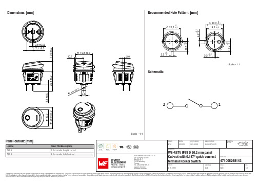
Würth Elektronik eiSos GmbH & Co. KGEMC & Inductive Solutions471006268143 Max-Eyth-Str. 174638 WaldenburgGermanyWürth Elektronik eiSos GmbH & Co. KGEMC & Inductive Solutions471006268143 Max-Eyth-Str. 174638 WaldenburgGermanyWürth Elektronik eiSos GmbH & Co. KGEMC & Inductive Solutions471006268143 Max-Eyth-Str. 174638 WaldenburgGermanyWürth Elektronik eiSos GmbH & Co. KGEMC & Inductive Solutions471006268143 Max-Eyth-Str. 174638 WaldenburgGermanyWürth Elektronik eiSos GmbH & Co. KGEMC & Inductive Solutions471006268143 Max-Eyth-Str. 174638 WaldenburgGermanyCautions and Warnings:The following conditions apply to all goods within the product series of WS-RSTV of Würth Elektronik eiSos GmbH & Co. KG:General:•This mechanical component is designed and manufactured for use in general electronic equipment.•Würth Elektronik must be asked for written approval (following the PPAP procedure) before incorporating the components into any equipment in fields such as military, aerospace, aviation, nuclear control, submarine, transportation (automotive control, train control,ship control), transportation signal, disaster prevention, medical, public information network, etc. where higher safety and reliability are especially required and/or if there is the possibility of direct damage or human injury.•Mechanical components that will be used in safety-critical or high-reliability applications, should be pre-evaluated by the customer. •The component is designed and manufactured to be used within the datasheet specified values. If the usage and operation conditions specified in the datasheet are not met, the component may be damaged or dissolved. •Do not drop or impact the components, the component may flake apart. •Prevent any damage or scratches on the switch, especially on the actuator.•Würth Elektronik products are qualified according to international standards, which are listed in each product reliability report. Würth Elektronik does not warrant any customer qualified product characteristics beyond Würth Elektroniks’ specifications, for its validity and sustainability over time.•The responsibility for the applicability of the customer specific products and use in a particular customer design is always within the authority of the customer. All technical specifications for standard products also apply to customer specific products.Product Specific:Soldering:•The solder profile must comply with the technical product specifications. All other profiles will void the warranty. •Hand soldering max. 350°C for 5 sec max..•All other soldering methods are at the customers’ own risk.•Please keep our switch at delivery original position before and during the soldering process.•Design the right angle part with consideration of the wave soldering process so that the parts will not touch the soldering wave during the soldering process or protect the switch part with cover fixture. Melting of the switch might cause malfunction.Cleaning and Washing:•If a series is washable, the general information section in the datasheet will contain the washability guidelines. Should there be no information regarding washability, the product has not been constructed to withstand a washing process. Washing agents used during the production to clean the customer application might damage or change the characteristics of the component, body, pins and/or termination. Washing agents may have a negative effect on the long-term functionality of the product.If the parts are washable, hermetic:•Cleaning agents that are used to clean the customer applications may damage or change the characteristics of the component, body,pins and termination.•Please do not immerse any washable products into water or cleaning agents or put them in locations exposed to water completely. •Do not clean washable series immediately after soldering. The cleaning agent may be absorbed into the switch through respiration while the switch cools.•Please do not press actuator or change status /position during the cleaning and washing process.•Using a brush during the cleaning process may deform function relevant areas. Therefore, we do not recommend using a brush during the PCB cleaning process.If the parts are not washable:•Parts are not constructed for washing. Washing may cause malfunctions.•When cleaning by hand (brushing), to avoid malfunction, do not use excessive force on switch. Excessive force can deform function relevant areas.Potting and Coating:•If the product is potted in the customer application, the potting material may shrink or expand during and after hardening. Shrinking could lead to an incomplete seal, allowing contaminants into the body, pins or termination. Expansion could damage the components.We recommend a manual inspection after potting or coating to avoid these effectsStorage Conditions:• A storage of Würth Elektronik products for longer than 12 months is not recommended. Within other effects, the terminals may suffer degradation, resulting in bad solderability. Therefore, all products shall be used within the period of 12 months based on the day of shipment.•Do not expose the components into direct sunlight.•The storage conditions in the original packaging are defined according to DIN EN 61760-2.•For a moisture sensitive component, the storage condition in the original packaging is defined according to IPC/JEDEC-J-STD-033. It is also recommended to return the component to the original moisture proof bag and reseal the moisture proof bag again.•The storage conditions stated in the original packaging apply to the storage time and not to the transportation time of the components.Packaging:•The packaging specifications apply only to purchase orders comprising whole packaging units. If the ordered quantity exceeds or islower than the specified packaging unit, packaging in accordance with the packaging specifications cannot be ensured.Würth Elektronik eiSos GmbH & Co. KG EMC & Inductive Solutions Max-Eyth-Str. 174638 Waldenburg GermanyCHECKED REVISION DATE (YYYY-MM-DD)GENERAL TOLERANCEPROJECTION METHODMTH003.0012023-03-29DIN ISO 2768-1mDESCRIPTIONWS-RSTV IP65 Ø 20.2 mm panel Cut-out with 0.187’’ quick connect terminal Rocker SwitchORDER CODE471006268143SIZE/TYPEBUSINESS UNITSTATUSPAGEHandling:Please refer to the pre-caution guide: www.we-online.de/precaution_rockerswitches_1These cautions and warnings comply with the state of the scientific and technical knowledge and are believed to be accurate and reliable.However, no responsibility is assumed for inaccuracies or incompleteness.Würth Elektronik eiSos GmbH & Co. KG EMC & Inductive Solutions Max-Eyth-Str. 174638 Waldenburg GermanyCHECKED REVISION DATE (YYYY-MM-DD)GENERAL TOLERANCEPROJECTION METHODMTH003.0012023-03-29DIN ISO 2768-1mDESCRIPTIONWS-RSTV IP65 Ø 20.2 mm panel Cut-out with 0.187’’ quick connect terminal Rocker SwitchORDER CODE471006268143SIZE/TYPEBUSINESS UNITSTATUSPAGEImportant NotesThe following conditions apply to all goods within the product range of Würth Elektronik eiSos GmbH & Co. KG:1. General Customer ResponsibilitySome goods within the product range of Würth Elektronik eiSos GmbH & Co. KG contain statements regarding general suitability for certain application areas. These statements about suitability are based on our knowledge and experience of typical requirements concerning the areas, serve as general guidance and cannot be estimated as binding statements about the suitability for a customer application. The responsibility for the applicability and use in a particular customer design is always solely within the authority of the customer. Due to this fact it is up to the customer to evaluate, where appropriate to investigate and decide whether the device with the specific product characteristics described in the product specification is valid and suitable for the respective customer application or not.2. Customer Responsibility related to Specific, in particular Safety-Relevant ApplicationsIt has to be clearly pointed out that the possibility of a malfunction of electronic components or failure before the end of the usual lifetime cannot be completely eliminated in the current state of the art, even if the products are operated within the range of the specifications.In certain customer applications requiring a very high level of safety and especially in customer applications in which the malfunction or failure of an electronic component could endanger human life or health it must be ensured by most advanced technological aid of suitable design of the customer application that no injury or damage is caused to third parties in the event of malfunction or failure of an electronic component. Therefore, customer is cautioned to verify that data sheets are current before placing orders. The current data sheets can be downloaded at .3. Best Care and AttentionAny product-specific notes, cautions and warnings must be strictly observed. Any disregard will result in the loss of warranty.4. Customer Support for Product SpecificationsSome products within the product range may contain substances which are subject to restrictions in certain jurisdictions in order to serve specific technical requirements. Necessary information is available on request. In this case the field sales engineer or the internal sales person in charge should be contacted who will be happy to support in this matter.5. Product R&DDue to constant product improvement product specifications may change from time to time. As a standard reporting procedure of the Product Change Notification (PCN) according to the JEDEC-Standard inform about minor and major changes. In case of further queries regarding the PCN, the field sales engineer or the internal sales person in charge should be contacted. The basic responsibility of the customer as per Section 1 and 2 remains unaffected.6. Product Life CycleDue to technical progress and economical evaluation we also reserve the right to discontinue production and delivery of products. As a standard reporting procedure of the Product Termination Notification (PTN) according to the JEDEC-Standard we will inform at an early stage about inevitable product discontinuance. According to this we cannot guarantee that all products within our product range will always be available. Therefore it needs to be verified with the field sales engineer or the internal sales person in charge about the current product availability expectancy before or when the product for application design-in disposal is considered. The approach named above does not apply in the case of individual agreements deviating from the foregoing for customer-specific products.7. Property RightsAll the rights for contractual products produced by Würth Elektronik eiSos GmbH & Co. KG on the basis of ideas, development contracts as well as models or templates that are subject to copyright, patent or commercial protection supplied to the customer will remain with Würth Elektronik eiSos GmbH & Co. KG. Würth Elektronik eiSos GmbH & Co. KG does not warrant or represent that any license, either expressed or implied, is granted under any patent right, copyright, mask work right, or other intellectual property right relating to any combination, application, or process in which Würth Elektronik eiSos GmbH & Co. KG components or services are used.8. General Terms and ConditionsUnless otherwise agreed in individual contracts, all orders are subject to the current version of the “General Terms and Conditions of Würth Elektronik eiSos Group”, last version available at .Würth Elektronik eiSos GmbH & Co. KGEMC & Inductive SolutionsMax-Eyth-Str. 174638 WaldenburgGermanyCHECKED REVISION DATE (YYYY-MM-DD)GENERAL TOLERANCE PROJECTIONMETHODMTH003.0012023-03-29DIN ISO 2768-1mDESCRIPTIONWS-RSTV IP65 Ø 20.2 mm panelCut-out with 0.187’’ quick connectterminal Rocker SwitchORDER CODE471006268143SIZE/TYPE BUSINESS UNIT STATUS PAGE。
欧诺克 直流无刷驱动器 产品说明书
深圳市欧诺克科技有限公司Shenzhen ONKE Technology Co., Ltd.座机:*************27381841电话:邓先生135****7106陈先生139****0920邮箱:***************网 址 : 地址:广东省深圳市宝安区福海街道怀德翠湖工业园13栋稳定的质量是我们赖以生存的根本优质的服务是我们继续发展的前提客户的满意是我们唯一追求的目标产品画册Product gallery专业生产直流无刷驱动器、无刷电机及自动化控制系统深圳市欧诺克科技有限公司直流无刷驱动器目录匠心制造精益求精“一、公司介绍03二、直流无刷驱动器091. 驱动器介绍与型号说明092. BC、BC2无刷系列技术指标113. 驱动器应用领域194. 驱动器外设配件21 0102C O M P A N Y PROFILE以精密制造引领未来Leading the future with precision manufacturing公司简介Company Profile深圳市欧诺克科技有限公司成立于2010年,是一家专业研发生产伺服电机和驱动器的高新技术企业,公司技术力量雄厚,检测手段先进,欧诺克人本着不求最全,只求最精的信念,为生产出各类伺服电机、各类驱动器而不懈奋斗。
欧诺克人以鹰的精神,挑战尖端,生产出性价比的各类伺服电机和驱动器,以鹰的敏锐洞察力洞察市场,随时改进、创新来满足市场的需求。
深圳市欧诺克科技有限公司产品主要有:伺服驱动器、伺服电机、直流伺服驱动器,直流伺服电机,交流伺服驱动器,交流伺服电机,低压伺服驱动器,低压伺服电机,直线电机驱动器,DDR马达驱动器,音圈电机驱动器,直流无刷驱动器,直流无刷电机,Rs485,CANopen总线,EtherCAT总线,电子凸轮伺服系统,大功率伺服驱动器、大电流伺服驱动器,专用伺服驱动器和自动化控制系统,十年来凭借精湛的技术与国内国外众多知名企业公司建立了互利共赢的合作。
DXM100-B2 无线控制器数据手册说明书

DatasheetThe DXM100-B2 Wireless Controller is an industrial wireless controller that facilitates Industrial Internet of Things (IIoT) applications.As a communications gateway, it interfaces local serial ports, local I/O ports, and local ISM radio devices to the internet usingeither a cellular connection or a wired Ethernet network connection.•Sure Cross ® DX80 Wireless Gateway or MultiHop radio with 900 MHz or 2.4 GHz ISM bands available•Logic controller with action rules and ScriptBasic programming •Cellular modem Internet connectivity•Automation protocols include Modbus TCP, Modbus RTU, and EtherNet/IP ™•Secure email and text Internet messaging for alarms, alerts, and data log files •Data logging with removable SD card•Interactive programmable user interface with LCD and LED indicators •Universal, on-board I/O with analog and discrete I/O•Industry standard RS-485, Ethernet, and USB communication ports •Multiple managed power options with battery backupWARNING:•Do not use this device for personnel protection•Using this device for personnel protection could result in serious injury or death.•This device does not include the self-checking redundant circuitry necessary to allow its use inpersonnel safety applications. A device failure or malfunction can cause either an energized (on) or de-energized (off) output condition.Important:•Never operate a 1 Watt radio without connecting an antenna•Operating 1 Watt radios without an antenna connected will damage the radio circuitry.•To avoid damaging the radio circuitry, never apply power to a Sure Cross ® Performance or Sure CrossMultiHop (1 Watt) radio without an antenna connected.Important:•Electrostatic discharge (ESD) sensitive device•ESD can damage the device. Damage from inappropriate handling is not covered by warranty.•Use proper handling procedures to prevent ESD damage. Proper handling procedures include leavingdevices in their anti-static packaging until ready for use; wearing anti-static wrist straps; and assembling units on a grounded, static-dissipative surface.Model Key for the DXM100-B2 ModelsB2 =Radio ConfigurationB2BaseDXM100-R1 = 900 MHz, 1 W PE5 Performance Radio (North America)R2 = 900 MHz, 1 W HE5 MultiHop Data Radio (North America)R3 = 2.4 GHz, 65 mW PE5 Performance Radio (Worldwide)R4 = 2.4 GHz, 65 mW HE5 MultiHop Data Radio (Worldwide)R5 = 900 MHz, 65 mW HE5L MultiHop Data Radio (Used for M-GAGE networks)R8 = 900 MHz, Performance Radios approved for Australia/New Zealand R9 = 900 MHz, MultiHop Radio approved for Australia/New ZealandSmart valve control, SDI-12 data collectionPower: 12−30 V dc/Solar/BatteryComms: RS-485, (1) SDI-12 sensor interface Inputs: (4) universal INOutputs: (4) NMOS OUT, (2) 0-10 V analog, (2) DC Latching Power Out: (2) Adjustable 5 V to 24 V switched power, (1) SDI switched power, and (1) 5 V courtesy powerSome example models include, but are not limited to, the following:Sure Cross ® DXM100-B2 Wireless ControllerOriginal Document 195232 Rev. E20 December 2018195232Cellular Communication —Controllers accept Banner GSM and LTE modems only. Cellular modems are ordered separately as accessories under the following part numbers:•GSM/3G (HSPA): SXI-GSM-001•LTE-Verizon: SXI-LTE-001DXM100 DocumentationFor more information about the DXM100 family of products, please see additional documentation and videos on the Banner website: .•DXM Wireless Controller Sell Sheet, p/n 194063•DXM100-B1 Wireless Controller Datasheet, p/n 186724•DXM100-B2 Wireless Controller Datasheet, p/n 195232•DXM100-Bx Wireless Controller Instruction Manual, p/n 190037•DXM100-S1 Modbus Slave Datasheet, p/n 195454•DXM100-S2 Modbus Slave Datasheet, p/n 195231•DXM100-Sx Modbus Slave Instruction Manual, p/n 188231•DXM ScriptBasic Instruction Manual, p/n 191745•DXM Controller Configuration Quick Start, p/n 191247•DXM Configuration Tool software (p/n b_4447978)•DXM Configuration Tool Instruction Manual, p/n 158447•DXM EDS Configuration file for Allen-Bradley PLCs•EIP Configuration File for DXM 1xx-BxR1 and R3 models (p/n 194730)•Activating a Cellular Modem (p/n b_4419353)•Additional technical notes and videosTechnical notes, configuration examples, and ScriptBasic program examples are available at .DXM100-B2 Wireless Controller System OverviewBanner's DXM Logic Controller integrates Banner's wireless radio, cellular connectivity, and local I/O to provide a platform for the Industrial Internet of Things (IIoT).Inputs/Outputs —On-board universal and programmable I/O ports connect to local sensors, indicators, and control equipment.•Universal Inputs •Discrete outputs •Courtesy power •Switch power•Battery backup •Solar controller•DC latching outputs •SDI-12 sensor interface - Tel: + 1 888 373 6767P/N 195232 Rev. EConnectivity—The DXM100's wired and wireless connectivity options make it easy to share data between local and remote equipment. The cellular modem option eliminates the need for IT infrastructures to connect remote equipment for sensing and control. The integrated Sure Cross® wireless radio enables Modbus connectivity to remote sensors, indicators, and control equipment.Wired ConnectivityEthernet: Modbus TCP or Ethernet/IPField Bus: Modbus RS-485 Master/Slave or CAN Wireless ConnectivitySure Cross Wireless Radio: DX80 900 MHz, DX80 2.4 GHz, MultiHop 900 MHz, or MultiHop 2.4 GHzCellular modem: CDMA (Verizon) or GSMLogic Controller—Program the DXM100's logic controller using action rules and/or ScriptBasic language, which can execute concurrently. The control functions allow freedom when creating custom sensing and control sequences. The logic controller supports the Modbus protocol standards for data management, ensuring seamless integration with existing automation systems.Action RulesSupports simple logic, arithmetic and thresholding Low complexity solutionsSMS text message NotificationsE-mail NotificationsPush data on conditionsText Programming LanguageScriptBasicMedium complexity solutions SchedulerTime/calendar-based events Astronomical clockData LoggingCyclic Data/Event loggingE-mail log filesSMS CommandingRead/Write Local RegistersForce a push to the cloudReboot controllerUser Interface—A simple user interface consists of an LCD screen and four LED indicators. Use the LCD to access system status and setup, view user selectable events or data, and to bind and perform site surveys for Sure Cross radios. Configure the user programmable LEDs to indicate the status of the DXM100, processes, or equipment.User programmable LCDBind Sure Cross RadiosSite SurveyView Sensor InformationSystem StatusUser Defined LED indicatorsApplications OverviewThe DXM100-B2 Wireless Controller is ideal for smart factory and facilities applications, including:•Productivity solutions, such as◦Call for parts, service, or maintenance◦Pick-to-light◦Tank level monitoring•Predictive maintenance and continuous monitoring using◦Vibration and temperature monitoring◦Non-contact temperature monitoring•Environmental monitoring and control, such as◦Temperature and humidity monitoring◦Irrigation and agricultural monitoringThe DXM100-B2 Wireless Controller can provide visual indication using indicator lights, send text or email alerts, collect data, and interface with automation systems.P/N 195232 Rev. E - Tel: + 1 888 373 67673SpecificationsMultiHop Radio SpecificationsRadio Range1900 MHz, 1 Watt: Up to 9.6 km (6 miles)2.4 GHz, 65 mW: Up to3.2 km (2 miles)Antenna Minimum Separation Distance900 MHz, 150 mW and 250 mW: 2 m (6 ft)900 MHz, 1 Watt: 4.57 m (15 ft)2.4 GHz, 65 mW: 0.3 m (1 ft)Radio Transmit Power900 MHz, 1 Watt: 30 dBm (1 W) conducted (up to 36 dBm EIRP)2.4 GHz, 65 mW: 18 dBm (65 mW) conducted, less than or equal to 20 dBm(100 mW) EIRPSpread Spectrum TechnologyFHSS (Frequency Hopping Spread Spectrum)900 MHz Compliance (1 Watt)FCC ID UE3RM1809: FCC Part 15, Subpart C, 15.247IC: 7044A-RM18092.4 GHz Compliance (MultiHop)FCC ID UE300DX80-2400: FCC Part 15, Subpart C, 15.247 RED Directive 2014/53/EUIC: 7044A-DX8024Antenna ConnectionExt. Reverse Polarity SMA, 50 OhmsMax Tightening Torque: 0.45 N·m (4 lbf·in)Radio Packet Size (MultiHop)900 MHz: 175 bytes (85 Modbus registers)2.4 GHz: 75 bytes (37 Modbus registers)RS-485 Communication SpecificationsCommunication Hardware (MultiHop RS-485)Interface: 2-wire half-duplex RS-485Baud rates: 9.6k, 19.2k (default), or 38.4k via DIP switches; 1200 and 2400 via the MultiHop Configuration Tool Data format: 8 data bits, no parity, 1 stop bitRS-232 Communication SpecificationsCommunication Hardware (MultiHop RS-232)Interface: 2-wire RS-232Baud rates: 9.6k, 19.2k (default), or 38.4k via DIP switches; 1200 and 2400 via the MultiHop Configuration Tool Data format: 8 data bits, no parity, 1 stop bitPower and I/O SpecificationsSupply Voltage12 to 30 V dc (use only with a suitable Class 2 power supply (UL) or a SELV(CE) power supply) or12 V dc solar panel and 12 V sealed lead acid batteryCourtesy Power OutOne output at 5 Volts, 500 mA maximumNo short circuit protectionSwitched Power OutputsTwo adjustable 5 V to 24 V outputsOne SDI-12 adjustable 5 V to 24 V output5 V: 400 mA maximum16 V: 125 mA maximum24 V: 85 mA maximumPower Consumption35 mA average at 12 Volts Solar Power12 V sealed lead acid battery2 A maximum charge current12 V, 20 W maximum solar panelSolar Power Battery Charging1 A maximum with 20 Watt solar panel Communication ProtocolsModbus RTU Master/Slave, Modbus/TCP, and Ethernet/IP Security ProtocolsVPN, SSL, and HTTPSLogging8 GB maximum; removable Micro SD card format ConstructionPolycarbonate; DIN rail mount optionCounters, Synchronous32-bits unsigned10 ms clock rate minimumUniversal InputsSinking/Sourcing discrete, 4–20 mA analog, 0–10 V analog, counter, and temperature 10 kOhm thermistor Analog Outputs (DAC)0 to 10 V dc outputAccuracy: 0.1% of full scale +0.01% per °CResolution: 12-bitDiscrete Output Rating (NMOS)Less than 1 A max current at 30 V dcON-State Saturation: Less than 0.7 V at 20 mA ON Condition: Less than 0.7 VOFF Condition: Open - Tel: + 1 888 373 6767P/N 195232 Rev. EEnvironmental SpecificationsOperating Conditions2–40 °C to +85 °C (–40 °F to +185 °F) (Electronics); –20 °C to +80 °C (–4 °F to +176 °F) (LCD)Micro CD Card (if applicable): –25 °C to +85 °C (–13 °F to +185 °F)95% maximum relative humidity (non-condensing)Radiated Immunity: 10 V/m (EN 61000-4-3)Shock and VibrationIEC 68-2-6 and IEC 68-2-27Shock: 30g, 11 millisecond half sine wave, 18 shocksVibration: 0.5 mm p-p, 10 to 60 Hz Environmental RatingIEC IP20Certifications(CE approval only appliesto 2.4 GHz models)AccessoriesFor a complete list of all the accessories for the Sure Cross wireless product line, please download the Accessories List (p/n b_3147091)CordsetsMQDC1-506—5-pin M12/Euro-style, straight, single ended, 6 ftMQDC1-530—5-pin M12/Euro-style, straight, single ended, 30 ftMQDC1-506RA—5-pin M12/Euro-style, right-angle, single ended, 6 ft MQDC1-530RA—5-pin M12/Euro-style, right-angle, single ended, 30 ft Misc AccessoriesBWA-CG.5-3X5.6-10—Cable Gland Pack: 1/2-inch NPT, Cordgrip for 3 holes of 2.8 to 5.6 mm diam, qty 10BWA-HW-052— Cable Gland and Vent Plug Pack: includes 1/2-inch NPT gland, 1/2-inch NPT multi-cable gland, and 1/2-inch NPT vent plug, qty 1 eachStatic and Surge SuppressorBWC-LFNBMN-DC—Surge Suppressor, bulkhead, N-Type, dc Blocking, N-Type Female, N-Type Male Antenna CablesBWC-1MRSMN05—LMR100 RP-SMA to N-Type Male, 0.5 mBWC-2MRSFRS6—LMR200, RP-SMA Male to RP-SMA Female Bulkhead,6 mBWC-4MNFN6—LMR400 N-Type Male to N-Type Female, 6 mShort-Range Omni AntennasBWA-2O2-D—Antenna, Dome, 2.4 GHz, 2 dBi, RP-SMA Box MountBWA-9O2-D—Antenna, Dome, 900 MHz, 2 dBi, RP-SMA Box MountBWA-9O2-RA—Antenna, Rubber Fixed Right Angle, 900 MHz, 2 dBi, RP-SMA Male ConnectorMedium-Range Omni AntennasBWA-9O5-C—Antenna, Rubber Swivel, 900 MHz 5 dBi, RP-SMA Male ConnectorBWA-2O5-C—Antenna, Rubber Swivel, 2.4 GHz 5 dBi, RP-SMA MaleConnector Long-Range Omni AntennasBWA-9O8-AS—Antenna, Fiberglass, 3/4 Wave, 900 MHz, 8 dBi, N-Type Female ConnectorBWA-2O8-A—Antenna, Fiberglass, 2.4 GHz, 8 dBi, N-Type FemaleConnectorLong-Range Yagi AntennasBWA-9Y10-A—Antenna, 900 MHz, 10 dBd, N-Type Female ConnectorEnclosures and DIN Rail KitsBWA-AH864—Enclosure, Polycarbonate, with Opaque Cover, 8 × 6 × 4 BWA-AH1084—Enclosure, Polycarbonate, with Opaque Cover, 10 × 8 × 4 BWA-AH12106—Enclosure, Polycarbonate, with Opaque Cover, 12 × 10 ×6BWA-AH8DR—DIN Rail Kit, 8", 2 trilobular/self-threading screwsBWA-AH10DR—DIN Rail Kit, 10", 2 trilobular/self-threading screwsBWA-AH12DR—DIN Rail Kit, 12", 2 trilobular/self-threading screws Power SuppliesPSD-24-4—DC Power Supply, Desktop style, 3.9 A, 24 V dc, Class 2, 4-pin M12/Euro-style quick disconnect (QD)PSDINP-24-13 —DC Power Supply, 1.3 Amps, 24 V dc, with DIN RailMount, Class I Division 2 (Groups A, B, C, D) RatedPSDINP-24-25 — DC Power Supply, 2.5 Amps, 24 V dc, with DIN RailMount, Class I Division 2 (Groups A, B, C, D) RatedBWA-SOLAR PANEL 20W—Solar Panel, 12 V, 20 W, Multicrystalline, 573 ×357 × 30, "L" style mounting bracket included (does not include controller)WarningsInstall and properly ground a qualified surge suppressor when installing a remote antenna system. Remote antenna configurations installed without surge suppressors invalidate the manufacturer's warranty. Keep the ground wire as short as possible and make all ground connections to a single-point ground system to ensure no ground loops are created. No surge suppressor can absorb all lightning strikes; do not touch the Sure Cross® device or any equipment connected to the Sure Cross device during a thunderstorm.Exporting Sure Cross® Radios. It is our intent to fully comply with all national and regional regulations regarding radio frequency emissions. Customers who want to re-export this product to a country other than that to which it was sold must ensure the device is approved in the destination country. A list of approved countries appears in the Radio Certifications section of the product manual. The Sure Cross wireless products were certified for use in these countries using the antenna that ships with the product. When using other antennas, verify you arenot exceeding the transmit power levels allowed by local governing agencies. Consult with Banner Engineering Corp. if the destination country is not on this list.P/N 195232 Rev. E - Tel: + 1 888 373 67675Banner Engineering Corp. Limited WarrantyBanner Engineering Corp. warrants its products to be free from defects in material and workmanship for one year following the date of shipment. Banner Engineering Corp. will repair or replace, free of charge, any product of its manufacture which, at the time it is returned to the factory, is found to have been defective during the warranty period. This warranty does not cover damage or liability for misuse, abuse, or the improper application or installation of the Banner product.THIS LIMITED WARRANTY IS EXCLUSIVE AND IN LIEU OF ALL OTHER WARRANTIES WHETHER EXPRESS OR IMPLIED (INCLUDING, WITHOUT LIMITATION, ANY WARRANTY OF MERCHANTABILITY OR FITNESS FOR A PARTICULAR PURPOSE), AND WHETHER ARISING UNDER COURSE OF PERFORMANCE, COURSE OF DEALING OR TRADE USAGE. This Warranty is exclusive and limited to repair or, at the discretion of Banner Engineering Corp., replacement. IN NO EVENT SHALL BANNER ENGINEERING CORP. BE LIABLE TO BUYER OR ANY OTHER PERSON OR ENTITY FOR ANY EXTRA COSTS, EXPENSES, LOSSES, LOSS OF PROFITS, OR ANY INCIDENTAL, CONSEQUENTIAL OR SPECIAL DAMAGES RESULTING FROM ANY PRODUCT DEFECT OR FROM THE USE OR INABILITY TO USE THE PRODUCT, WHETHER ARISING IN CONTRACT OR WARRANTY, STATUTE, TORT, STRICT LIABILITY, NEGLIGENCE, OR OTHERWISE.Banner Engineering Corp. reserves the right to change, modify or improve the design of the product without assuming any obligations or liabilities relating to any product previously manufactured by Banner Engineering Corp. Any misuse, abuse, or improper application or installation of this product or use of the product for personal protection applications when the product is identified as not intended for such purposes will void the product warranty. Any modifications to this product without prior express approval by Banner Engineering Corp will void the product warranties. All specifications published in this document are subject to change; Banner reserves the right to modify product specifications or update documentation at any time. Specifications and product information in English supersede that which is provided in any other language. For the most recent version of any documentation, refer to: .For patent information, see /patents.© Banner Engineering Corp. All rights reserved。
DRTⅡ系列使用说明手册
,连接上之后按钮会变成绿色
。
测试移动控制及限位开关是否正常
测试限位开关是否正常工作:
点击“同时归位”按钮 ,打 印机执行归位动作,归位后分别操作 X、Y、Z 移动,检测运动是否正常。
此按钮是 X 轴归为按钮, Y、Z 同是如此;点击之后相应的 轴方向会执行归位动作。
此按钮是 X、 Y、Z 三轴同时归位按钮。 注意:在机器没有归位的时候,机器只能在单边区域运动;如果你对打印机 操作不是很熟悉,每次移动的距离不要太大。 测试温度检测系统及加热系统是否正常(挤出装置和热床检测)
“完成”。 B:如果你使用手动安装程序,选择“从列表或指定位置安装”,然后选择驱
4
芜湖瀚博电子科技有限公司——DRTⅡ系列使用说明手册
动所在目录,最后点击安装。(与普通驱动程序手动安装方法相同)。 如果你是 XP 右键单击桌面上的“我的电脑”; 如果你是 WIN7 请右键单击
“计算机”、选择点击“管理”,点击计算机中的“设备管理器”。如下图所示:
1、连接上位机软件
在 SD 卡文件里,打开上位机软件,找到“瀚博 3D 打印操 作系统”。
双击弹出瀚博 3D 打印系统 弹出窗口如下:
在菜单栏中,
பைடு நூலகம்
单击
“配置”,再单击“打印机设置”, 单击出现打印
机设置窗口(如右下图所示)。
6
芜湖瀚博电子科技有限公司——DRTⅡ系列使用说明手册
选择端口,我的端口是 COM145,你还记得你的端口 吗?选择你的,其他必须跟下 面的一样(特别是波特率选项)。
如果你的电脑是 Windows 操作系统,请按以 下步骤操作:
1、 请先安装 dotnetfx35 文件,安装时最好断开网络,这样安装速度会快。 (备注:WIN7 或 WIN7 以上版本操作系统不需要安装此软件,系统自带)
DRX-2.3 用户手册说明书
目录 ≫连接≫- 连接扬声器 ≫播放 ≫设置 ≫故障排除≫附录 ≫补充信息≫A V Receiver使用手册DRX-2.3包装箱中的物品 5附加功能(固件更新) 6固件更新信息 6新增功能操作 6固件更新步骤 7零件名称 10前面板 10显示屏 12后面板 13遥控器 15连接连接扬声器 17扬声器安装 18扬声器连接和“Speaker Setup”设置 24扬声器组合 33连接电视 34连接 ARC 电视 35连接非 ARC 电视 36连接播放设备 37连接装有 HDMI 接口的 AV 设备 37连接无 HDMI 接口的 AV 设备 38连接音频组件 39连接单独房间中的 AV 设备(多区域连接) 40连接电视(ZONE 2) 40连接 ZONE B 41连接前置主放大器等(ZONE B) 41连接天线 42网络连接 43连接外部控制设备 44 IR IN/OUT 端口 44 12V TRIGGER OUT 接口 45连接电源线 46播放AV 设备播放 48基本操作 48 BLUETOOTH®播放 49基本操作 49网络电台 50播放 50 AirPlay® 52基本操作 52 DTS Play-Fi® 53播放 53 FlareConnect TM 54播放 54 USB 存储设备 55基本操作 55设备和支持的格式 57播放 PC 和 NAS(音乐服务器)上的文件 58 Windows Media® Player 设置 58播放 59支持的音频格式 61 Play Queue 62 Initial Setup 62添加 Play Queue 信息 62排序和删除 63播放 63将您的机器连接到 Sonos System 64所需设备 64将您的机器连接到Sonos Connect 64设置本机,以运行 Sonos Connect 64现在到了享受成果的时候 - 在您的机器上听 Sonos 65收听 AM/FM 电台 66调谐至一个无线电台 66预设无线电台 68使用 RDS(澳大利亚及亚洲产品类型) 70多区域功能 71播放 72 ZONE B 播放 73播放 73便利功能 74播放音乐时在电视上显示您最喜欢的视频 74调整音调 75 Sleep Timer 76聆听模式 77选择聆听模式 77扬声器布局和可选聆听模式 79聆听模式效果 82输入格式和可选聆听模式 86设置Setup 菜单 97菜单列表 97菜单操作 991. Input/Output Assign 1002. Speaker 1033. Audio Adjust 1074. Source 1095. Listening Mode Preset 1106. Hardware 1117. Multi Zone 1198. Miscellaneous 119 Quick Menu 121菜单操作 121 Web Setup 123菜单操作 123使用自动启动向导进行 Initial Setup 124操作 124故障排除当本机错误运行 128故障排除 130附录降低待机状态下的功耗139关于 HDMI 140一般规格 1421. 主机(1)Array2. 遥控器(RC-973R)(1)3. 扬声器设置麦克风(1)• 在 Initial Setup 过程中使用。
TopWorx D-Series 控制器安装、操作与维护指南说明书

TopWorx ™ D-Series Valve ControllersMaster Installation, Operation & Maintenance Manual35 Series GO™ Switches35-13319M Option L2/L4 - SPDT35-83358M Option Z2/Z4 - DPDT Stainless SteelSwitch / Module Replacement KitsAV-FFD2-1Foundation Fieldbus module replacement ( with piezo pilots) AV-FFD2-2Foundation Fieldbus module replacement ( without piezo pilots) AV-AS1-1AS-Interface moduleAV-DN1-1DeviceNet moduleAV-PB1-1Profibus ModuleAV-MSW1 (M) SPDT mechanical switch replacementAV-E1 (E) P+F NJ2-V3-N sensor replacementAV-TSW1 (T) DPDT mechanical switch replacementAV-420TBD4-20mA transmitter replacement assemblyAV-420HBD Hart Board ReplacementIndicator / Dome Replacement KitsAV-GB00290º, Green/Open, Red/Closed, Buna O-RingAV-YB00290º, Yellow/Open, Black/Closed, Buna O-RingAV-BB00290º, Black/Open, Yellow/Closed, Buna O-RingAV-4B00245º, Green/Open, Red/Closed, Buna O-RingShaft Replacement KitsMechanical Switches (M2 or T2)AV-SSB201 Standard shaftBuna-N O-Rings & (2) cam Assembly w/ HardwareAV-NSB201 NAMUR ShaftBuna-N O-Rings & (2) cam Assembly w/ HardwareShaft Replacement KitsGO™ Switches (L2 - Manufactured after July 1, 2007)AV-SSB205 Standard shaftBuna-N O-Rings & (2) Target Assembly w/ HardwareAV-SNB205 NAMUR shaftBuna-N O-Rings & (2) Target Assembly w/ HardwareShaft Replacement Kits SCMs with Reed Switches (R2)AV-NSB202NAMUR ShaftBuna-N O-Rings & (2) cam Assembly w/ HardwareAV-SSB202Standard ShaftBuna-N O-Rings & (2) cam Assembly w/ HardwareConsult FactoryTo order replacement parts or for information concerning parts or spool valve options not listed callTopWorx™ at 502-969-800052Pilot Replacement KitsAV -S24VPMRK 24vdc pilot/manifold replacement kitAV-S110VPMRK 110vac pilot/manifold replacement kitAV-A220PMRK220 VAC pilot/manifold replacement kitAV-SP20PMRK Piezo pilot/manifold replacement kitSpool Valve Replacement AssembliesAV-AB1A20ASCO 8551 Spool Valve, Fail Open/Closed, Aluminum AV-AB1620ASCO 8551 Spool Valve, Fail Open/Closed, SSTAV-AV2A20ASCO 8551 Spool Valve, Fail Last, AluminumAV-AB2620ASCO 8551 Spool Valve, Fail Last, SSTAV-AB1A30ASCO 8553 Spool Valve, Fail Open/Closed, Aluminum AV-AB1630ASCO 8553 Spool Valve, Fail Open/Closed, SSTAV-AB2A30ASCO 8553 Spool Valve, Fail Last, AluminumAV-AB2630ASCO 8533 Spool Valve, Fail Last, SST53。
XR-2控制器说明书
XR-2控制器说明书
XR-2控制器说明书
⼀⽤⼀备、故障互投、故障报警、增载减载
XR-2控制器使⽤说明:
1、两台电机分别接9号和0号端⼦、9号和10号端⼦(输出电压AC220V,接交流接触器线圈);报警输出接9号和11号端⼦;
2、接线说明,如下图:
3、运⾏流程图:
4、电源输⼊8号和9号端⼦,为宽电压(AC86V-AV260V可⽤)。
3路AC220V输出:9号端⼦为公共线,每路和9号端⼦之间输出电压为输⼊电压,输出电流需控制在10A内。
5、故障信号(⽆源信号):GM为公共端,D1故障时,GM和G1闭合;D2故障时,GM和G2闭合。
6、外部信号输⼊(⽆源信号):可配接3个⽔位点(最少需要接两个⽔位点,实现控制器⾃动功能)。
1号端⼦(公共)和2号端⼦闭合,D1运⾏;1号端⼦和2号端⼦断开,D1停⽌运⾏;1号端⼦和2号端⼦再闭合,D2运⾏;1号端⼦和2号端⼦再断开,D2停⽌运⾏;如此反复,实现⼀⽤⼀备功能。
1号端⼦和2号端⼦闭合,再同时闭合3号端⼦,D1和D2会同时运⾏,实现增载功能;3号端⼦断开,后启的电机停⽌运⾏,实现减载功能。
7、在D1运⾏或者D1和D2同时运⾏时,遇D1或D2故障,D3闭合报警,故障电机⾃动停⽌⼯作。
即:G1和GM闭合时,D1断开,同时D2闭合,D3闭合报警;G2和GM闭合时,D2断开,同时D1运⾏,D3闭合报警。
8、G1和GM接A泵输出的反馈故障信号,如:D1热继电器的常开触点;G2和GM接B泵输出的反馈故障信号,如:D2热继电器的常开触点。
9、免责:控制器只做⼀般设备控制使⽤。
10、⽔位⽰意图:
技术⽀持:188********。
飞控控制卡扩展功能使用说明书

飞控控制卡扩展功能使用说明书1 温湿度使用说明...................................................................................................................... -2 -1.1 支持的传感器型号....................................................................................................... - 2 -1.2 支持的控制卡型号....................................................................................................... - 2 -1.3 传感器焊接说明........................................................................................................... - 3 -1.4 温度编辑注意点........................................................................................................... - 4 -2 红外遥控使用说明.................................................................................................................. - 5 -2.1 红外遥控器及接收头型号........................................................................................... - 5 -2.2 支持的控制卡型号....................................................................................................... - 5 -2.3 红外接收头焊接说明................................................................................................... - 6 -2.4 使用说明....................................................................................................................... - 7 -3. 恢复出厂设置....................................................................................................................... - 10 -3.1 概述............................................................................................................................. - 10 -3.2 软件恢复出厂设置..................................................................................................... - 10 -3.3 硬件恢复出厂设置..................................................................................................... - 11 -1 温湿度使用说明1.1 支持的传感器型号1. A型—温度+湿度传感器:AM23012. B型—单温度传感器:DS18B201.2 支持的控制卡型号1. 支持A型—温度+湿度的卡型号如下:所有的二代卡(除A2)都支持;三代卡都支持(除SU3)。
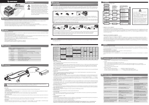
HOBBYWING XR10 Justock 高性能传感器无线电速控器用户手册说明书
01Introduction03Features02Warnings04Specifications05Connections06ESC SetupESC/Radio CalibrationThank you for purchasing the XR10 Justock, HOBBYWING’s highperformance sensorless brushless motor electronic speed controller! Brushless power systems can be very dangerous. Any improper use may 1USER MANUALXERUN XR10 JustockBrushless Electronic Speed Controller• Compact design for easy installation.• Compatible with sensored/sensorless brushless motors. In sensored mode, it’s compatible with most popular sensored brushless motors on the market. In sensorless mode, it’s compatible with 99% of brushless motors on the market.• Aluminum housing top with excellent heat dissipation and great current endurance.• The timing has been permanently set to 0 degree. With the identical competition motor, this ensures that every driver will have the same power system and have a really just STOCK race. • Proportional brake with 4 steps of maximum brake force, 8 steps of drag brake force and 4 steps of initial brake force.• 9 levels of acceleration/ punch from “soft” to “aggressive” for different vehicles, tires and tracks.• Multiple protections: motor lock-up protection, low-voltage cutoff protection, thermal protection and fail safe (throttle signal loss protection).• Single-button ESC programming and factory reset.• Advanced programming via portable LED program card or multifunction LCD program box.• Firmware upgrade via HOBBYWING multifunction LCD program box (item sold separately).1. Motor WiringThe sensored motor wiring is a little different from the sensorless motor wiring; please make sure that you will strictly follow the introductions below. A. Sensored Motor WiringThere is strict wiring order from the ESC to the motor, the three A/B/C ESC wires must connect to the three A/B/C motor wires correspondingly and then connect the ESC sensor port and the motor sensor port with the stock 6-pin sensor cable.Note 1: If you don’t plug the sensor cable in, your ESC will still work in sensorless mode even if you’re using a sensored motor. B. Sensorless Motor WiringThere is no polarity on the A/B/C wires between ESC and motor, so do not worry about how you connect them initially. You may find it necessary to swap two wires if the motor runs in reverse. 2. Receiver WiringPlug the throttle control cable (also called Rx cable) on the ESC into the throttle (TH) channel on receiver. The red wire in the throttle control cable will output the BEC voltage of 6V to the receiver and servo, so please do not connect any additional battery to the receiver. Otherwise, your ESC may be damaged.3. Battery WiringProper polarity is essential here! Make absolutely sure positive (+) of ESC connects to positive (+) of battery, and negative (-) of ESC connects to negative (-) of battery when you plug in your battery! If reverse polarity is applied to your ESC from the battery, it will damage your ESC. This will not be covered under warranty!In order to make the ESC match the throttle range, you must calibrate it when you begin to use a new ESC, or a new transmitter, or after you change the settings such as the TRIM, D/R, EPA Warning Tones2Turn on the ESC in the normal way (that is to turn it on without holding the SET button); the motor will beep the number of LiPo cells you have plugged in. For example, 2 beeps indicate a 2S LiPo, 3 beeps indicate a 3S LiPo.Programmable Items3(Those "black backgroud and white text" options are the factory default settings)1. Running ModeOption 1: Forward with BrakeThe vehicle can go forward and brake but cannot reverse in this mode. This mode is usually for racing. Option 2: Forward/Reverse with BrakeThis mode provides the braking function, it’s usually for training. “Forward/Reverse with Brake” mode adopted the “DOUBLE-CLICK” method, that is your vehicle only brakes (won’t reverse) when the 1st time you push the throttle trigger forward (away from you) (1st push). If the motor stops when you quickly release the throttle trigger and then re-push the trigger quickly (2nd push), the vehicle will reverse. If the motor does not stop, then your vehicle won’t reverse but brake, you need to push the throttle trigger one more time. The vehicle only reverses after the motor stops. This method is for preventing vehicle from being accidentally reversed. Option 3: Forward/ReverseThis mode used the “SINGLE-CLICK” method to make the car go backward. When you move the throttle trigger from forward zone to backward zone, the car will go backward immediately. This mode is usually used by special vehicles like the rock crawler.2. Drag Brake ForceDrag brake is the braking power produced when releasing the throttle trigger to neutral zone. This is to simulate the slight braking effect of a neutral brushed motor while coasting. (Attention! Drag brake will consume much power, so please apply it cautiously.)3. Cutoff Voltage (or Low Voltage Cutoff Threshold)Sets the voltage at which the ESC lowers or removes power to the motor in order to keep the LiPo battery at a safe minimum voltage. The ESC will monitor the battery voltage all the time, it will gradually reduce the power to 30% in 3 seconds (at this time, racer should pull the car aside and drop out of the race immediately to avoid blocking the track or hitting by some car comes behind.) and cutoff the output 10 seconds later when the voltage goes below the cutoff threshold. The RED LED will flash a short, single flash that repeats (☆-, ☆-, ☆-) to indicate the low-voltage cutoff protection is activated. If necessary, you can customize the cutoff voltage at the precise step of ±0.1V through a multifunction LCD program box (item sold separately)for different battery packs like NiMH, LiFe and etc. 4. Start Mode / Punch /AccelerationYou can choose the punch from level 1 (very soft) to level 9 (very aggressive) as per the track, tires, grip, your preference and etc. This feature is very useful for preventing tires from slipping in the starting-up process. In addition, “level 7”, “level 8 and “level 9” have strict requirement on battery’s discharge capability. It may affect the starting-up if the battery discharges poorly and cannot provide large current in a short time. The car stutters or suddenly loses power in the starting-up process indicating the battery’s discharge capability is not good; you need toreduce the punch or increase the FDR (Final Drive Ratio).5. Brake Amount/ Max. Brake ForceThis ESC provides the proportional braking function; the braking effect is determined by the position of the throttle trigger. It sets what percentage of available braking power is applied with full brake. Large amount will shorten the braking time but it may damage your pinion and spur. Please select the most suitable brake amount as per your car condition and your preference.6. Reverse Amount/ Max. Reverse ForceDifferent reverse amount will bring different reversing speed. For the safety of your vehicle, we recommend using a low amount.7. Maximum Reverse Force:Sets how much power will be applied in the reverse direction. Different value makes different reverse speed. 8. Throttle Neutral RangeAdjust the throttle neutral zone as per your preference (as shown). Because the neutral position on some transmitters is not stable and it can cause the vehicle to go forward/backward slowly, so please set the throttle neutral width to a bigger value when this issue happens. 9. Timing:This item has been permanently set to “0” degree. 10. Overheat Protection:If this item is activated, the output will be automatically cut off when the ESC temperature or the internal temperature of the sensored brushless motor goes above the factory preset value. The Green LED will flash when this protection is activated. The output won’t resume until the ESC/motor cools down. When the ESC is overheated, the Green LED will flash a short, single flash that repeats “☆-, ☆-, ☆-”.When the motor is overheated, the Green LED will flash a short, double flash that repeats “☆-☆-, ☆-☆-, ☆-☆-”.Note: The motor overheat protection is only available to the sensored brushless motor manufactured by the same manufacturer of this ESC. For motors made by other manufacturers, this function may not be available or the protection point doesn’t match the design of the ESC, please disable the overheat protection in this case.(For more information, please refer to the user manual of the LCD program box.)You can program this ESC through a 3-in-1 LCD program box or through a 3-in-1 LCD program box and a PC (HOBBYWING USB LINK software needs to be installed on the PC). Before theprogramming, you need to unplug the throttle control cable (or Rx cable) from the receiver and plug it into the programming/ESC port on the program box, then the boot screen will show up on the LCD, press any button on the program box to initiate the communication between your ESC and the program box,. The “CONNECTING ESC” will be displayed, a few seconds later; the program box will display the current mode like profile 1 and then the 1st programmable item like running mode. You can adjust the setting through “ITEM” & “VALUE” buttons, and then press the “OK” button to save new settings to your ESC.07Explanations for Different Status LEDs08Trouble ShootingFactory Reset5• Restore the default values with the SET buttonPress and hold the SET button for over 3 seconds anytime when the throttle trigger is at the neutral position (except during the ESC calibration and programming) can factory reset your ESC. RED & GREEN LEDs flash simultaneously indicating you have successfully restored all the default values within your ESC. Once you power the ESC off, and then back on, your settings will be back in the default mode.• Restore the default values with the LED program boxAfter connecting the program box to the ESC, press the “RESET” button and the “OK” button to factory reset your ESC.• Restore the default values with a multifunction LCD program boxAfter connecting the program box to the ESC, continuously press the “ITEM” button on the program box until you see the “RESTORE DEFAULT” item, and then press “OK” to factory reset your ESC.1. During the Start-up Process• The GREEN LED flashes “N” times indicating the number of LiPo cells you have connected to the ESC.2. In Operation• The RED LED flashes rapidly when the throttle trigger is in the throttle neutral zone.• The RED LED turns on solid when your vehicle runs forward. The GREEN LED will also come on when pulling the throttle trigger to the full (100%) throttle endpoint.• The RED LED turns on solid when you brake your vehicle. The GREEN LED will also come on when pushing the throttle trigger to the full brake endpoint and setting the “brake amount/maximum brake force” to 100%.• The RED LED turns on solid when you reverse your vehicle.3. Some Protection is Activated• The RED LED flashes a short, single flash that repeats (☆-, ☆-, ☆-) indicating the low voltage cutoff protection is activated. • The GREEN LED flashes a short, single flash that repeats (☆-, ☆-, ☆-) indicating the ESC thermal / overheat protection is activated. • The GREEN LED flashes a short, double flash that repeats (☆☆-, ☆☆-, ☆☆-) indicating the motor thermal /overheat protection is activated.Trouble(s)Solution(s)Possible Causes1. No power was supplied to the ESC.2. The ESC switch was damaged.1. Check if all ESC & battery connectors have been well soldered or firmly connected.The ESC was unable to start the status LED, the motor, and thecooling fan after it was powered on.• Ensure all wires and connections are well insulated before connecting the ESC to related devices, as short circuit will damage your ESC.• Ensure all devices are well connected, in order to prevent poor connections that may cause your vehicle to lose control or other unpredictable issues like damage to the device.• Read through the manuals of all power devices and chassis and ensure the power configuration is rational before using this unit. • Please use a soldering iron with the power of at least 50W to solder all input/output wires and connectors.• Stop using the ESC when its casing temperature exceeds 90℃/194℉; otherwise your ESC will get destroyed and may also get your motor damaged.• Always disconnect and remove batteries after use, as the ESC will continue to consume current if it’s still connected to batteries (even if the ESC is turned off). Long-time contact will cause batteries to completely discharge and result in damage to batteries or ESC or both. This will not be covered under warranty.)20170109。
控制器2.0说明书 (1)
控制器使用说明书V2.0第一章概述 (2)第二章操作说明 (3)2.1面板说明 (3)2.2 按键定义说明 (4)2.3 数码管显示说明 (4)2.4操作步骤 (5)2.4.1报站操作 (5)2.4.2线路下载操作 (5)2.4.3线路选择操作 (6)2.4.4配置文件的创建 (6)第三章安装与接线 (7)3.1外形尺寸和安装说明 (7)3.1.1外形尺寸 (7)3.1.2 控制器安装 (8)3.2接线定义 (9)3.3安装说明 (9)3.3.1安装环境要求 (9)3.3.2安装注意事项 (10)3.3.3 安装部件和材料要求 (10)附件1:线路txt文件内容编写说明 (11)附件二:TXT文件示例 (15)第一章概述感谢您使用V2.0控制器。
本手册提供用户关于安装、运行操作、异常诊断等方面的使用方法,为确保V2.0控制器的稳定运行,在安装使用之前,请仔细阅读本说明书并妥善保存。
V2.0控制器是专为公交系统设计的一款控制LED电子路牌的产品。
它采用了嵌入式微处理器和嵌入式系统,结合了USB通信技术、RS485通信技术,实现了电子路牌的中央控制,信息下载及线路管理。
外观简洁、抗震,安装灵活方便,功能强大,系统运行稳定,可广泛应用于城市公交系统。
V2.0控制器具有以下功能:与LED电子路牌联动,自动更新线路号、首末站点信息;可以保存32条线路,方便车辆调度;可根据不同客户需求更新相应字库(黑体、细黑、宋体……);车内屏报站,可以控制下一站或即将到站的信息显示;控制站节牌站点号显示及上下行信息;满足第三方协议,更新路牌线路信息;键盘控制(3个按键),方便设置或手动报站;3位数码管显示线路号、站点号、上下行信息等;USB接口,自动下载线路信息、字库文件、广告屏信息(由配置文件);宽电源输入:DC 9~36V控制器2.0系统框架图第二章操作说明2.1面板说明图2.1 控制器的面板按键说明图1)按键:共4个按键,每个按键分长按键和短按键功能,操作人员可通过按键设置控制器;2)USB接口:下载线路信息(或广告屏显示信息);切记:勿用该接口给手机充电;3)指示灯:◆电源指示灯:通电状态下电源指示灯亮;◆USB指示灯:灯亮表示接入的U盘被识别,开始自动下载线路信息;◆报站指示灯:灯亮表示此时控制器为报站状态,按<、ok、>等键可以控制车内屏报站,或长按<、>键控制上、下行方向,控制器开机时默认为报站状态;◆线路指示灯:灯亮表示此时控制器为线路选择状态,按<、ok、>等键可以选择存储在控制器内的某一条线路信息;4)显示区:3位数码管显示线路号站点号、上下行信息;2.2 按键定义说明2.1按键定义说明按键功能短按此键:上翻选择键,出站键,播放屏幕显示站点的上一站出站信息。
西尔特电子SUPERPRO X108编程器用户手册说明书
重要信息:1.本说明书适用于SUPERPRO/X108.2.为了能方便快速的连接编程器,请在安装软件后连接硬件。
3.使用编程器前,请仔细阅读说明书。
4.请不要使用自制适配器。
自制适配器会导致联机错误,请选购Xeltek公司的原装适配器。
版权声明软件版权2018-2028 XELTEK用户手册版权2018-2028 XELTEKSUPERPRO For Windows 软件及本用户手册版权归西尔特电子有限公司所有。
产品的发行和销售由原始购买者在许可协议条款下使用。
未经西尔特电子有限公司允许,任何单位及个人不得将该产品全部或部分复制、照相、再生、翻译或还原成其它机器可读形式的电子媒介。
本手册若有任何修改恕不另行通知。
因软件版本升级而造成的与本手册不符,以软件为准。
SUPERPRO®是XELTEK南京西尔特电子有限公司的注册商标。
第一章总述 (1)1.1 简介 (1)1.1.1 什么是SUPERPRO ? (1)1.1.2 软件特点(USB2.0系列): (1)1.1.3 手册组织 (1)1.1.4 系统要求 (1)1.1.5 编程器包装 (2)第二章安装 (3)2.1安装编程器应用软件 (3)2.1.1 从随机的CD-ROM盘上安装 (3)2.1.2 从Internet网上下载安装软件(推荐) (3)2.1.3 软件安装过程 (3)2.1.4 连接硬件和驱动程序的安装 (8)2.1.5 运行编程器应用软件 (8)第三章快速入门 (10)3.1 应用软件的用户界面 (10)3.2 烧录器件的步骤 (12)3.2.1 硬件准备 (12)3.2.2 选择器件 (12)3.2.3 将数据装入缓冲区 (13)1) 从文件读取 (13)2) 从母片中读取数据 (13)3.2.4 设置选项 (13)1) 操作选项 (13)2)编辑Auto (14)4) 器件信息 (14)5) 量产模式 (14)3.2.5 编程,将缓冲区的数据烧录到芯片中 (14)3.2.6 安全性与密码输入 (15)3.3工程文件 (15)3.4 数台并联烧写 (16)4.1 浏览菜单和工具条 (18)4.1.1文件和数据 (18)4.1.1.1 载入文件 (18)4.1.1.2 保存文件 (21)将当前缓冲区数据存入磁盘文件中。
Futaba S3010 电控系列说明书
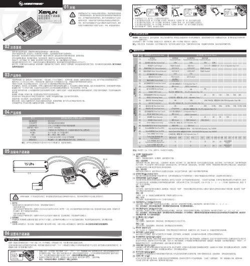
感谢您购买本产品!无刷动力系统功率强大,错误的使用可能造成人身伤害和设备损坏。
我们强烈建议您在使用设备前仔细阅读本说明书,并严格遵守规定的操作程序。
我们不承担因使用本产品而引起的任何责任,包括但不限于对附带损失或间接损失的赔偿责任;同时,我们不承担因擅自对产品进行修改所引起的任何责任。
我们有权在不经通知的情况下变更产品设计、外观、性能及使用要求。
· 电调与相关连接部件连接前,请确保所有电线和连接部件绝缘良好,短路会毁坏电调。
· 请务必仔细连接好各部件,若连接不良,您可能不能正常控制赛车,或出现设备损坏等其他不可预知的情况。
· 使用此电调前,请认真查看各动力设备以及车架说明书,确保动力搭配合理,避免因错误的动力搭配导致电机超载,最终损坏电调。
· 内置多种常用模式(如:零进角Zero Timing闪灯模式、一般练习模式、STOCK 竞赛模式),适合所有竞赛,即选即用。
电调的设定参数可以导入导出,便于车手相互交流和借鉴彼此的设定。
· 体积非常之小(31.6x25.8x16.2mm),车架布局更方便;重量非常之轻(不含线重量仅为23.5g),低重量为车架的平衡提供更多的可调空间。
· 内置BEC升压电路,BEC最大输出电流高达6A,且支持 6V和7.4V 切换,轻松驱动各种强力舵机及高压舵机。
03产品特色02注意事项05连接电子调速器06设置电子调速器设定油门行程1XERUN XR10 STOCK SPEC 1S车用无刷电子调速器使用说明书01声明1. 连接马达:连接有感无刷马达与无感无刷马达的方式有差异,请务必遵照如下接线方式: · 连接有感无刷马达时:电调与马达相连有严格的线序要求,电调的#A/#B/#C必须与电机的#A/#B/#C三线严格一一对应,用6针感应线把电调与电机的感应口对接。
若有感无刷马达未接上感应线,则电调会工作 在无感模式,相当于电调连接无感无刷电机。
TX2RX2 五功能遥控器
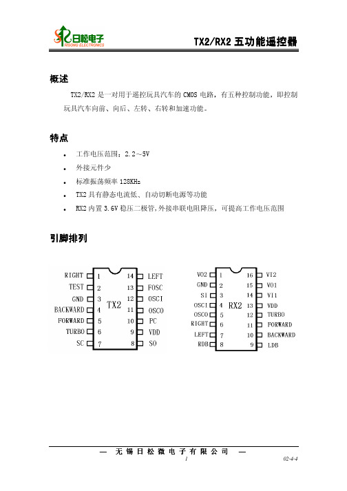
范围
0.3V 5.0V GND-0.2V VDD+0.2V 10 60 25 125
说明 上述参数绝对不允许超出 否则器件将受到永久性损坏 也不能在临界条件下长时间工作 否则即使不损坏器件也会影响器件的可靠性
电参数
TX2
VDD = 4V, FOSC = 128KHZ, 除非另有说明 TA = 250C
28 34 40 46 52 58 64
解码结果 RX2
起始码 前进 前进 加速 前进 向左 前进 向右 后退 后退 向右 后退 向左 向左 向右
— 无锡日松微电子有限公司 —
5
02-4-4
典型应用电路
发射器(TX-2 Fosc 128KHZ)
TX2/RX2 五功能遥控器
14
13
LEFTB FOSC
100µF
+ -
VCC RF. Circuit GND
16 15 14 13 4.3V VI2 VO1 VI1 VDD
12 TURBO
11
10
FORWARD BACKWARD
VO2 GND SI OSCI
RX-2
OSCO
1
2
3
4
5
B500 KOhm
RIGHT 6
LEFT 7
9 LDB
ROB 8
power switch
B500 KOhm
12
11
OSCI
OSCO
10 PC
9
8
VDD
SO
TX -2
R IG H T B T E ST B G N D B A C K W A R D B FO RW A R D B T U R B O B S C
莱茵 XS 无线数字驱动器接收器说明书

FEATURES• One touch ease-of-use• 2.4 GHz digital transmission for worldwide operation • 75 m range (250 ft) in optimal conditions • Up to 5 hours battery life on a single charge • Switch between multiple transmitters linked to onereceiverDELIVERY INCLUDES• XSW-D Pedalboard receiver • USB-C to USB-C charging cable • Colored stickers for labelling • Quick guide • Safety guideUSB C interface Output voltage 5 VOutput current typ. 380 mA Input voltage 5 VCurrent consumptionmax. 185 mAExternal power supply interface Input voltage 9 - 15 V, typ. 12 V Current consumption max. 500 mA @ 9 VAF characteristics CodecaptX® Live Audio frequency response 10 - 18,000 Hz Audio output max. 12 dBu Signal-to-noise ratio ≥ 106 dB THD< 0.1 %Audio latency < 4 msProduct properties Dimensions approx. 130 x 82 x 51 mm Weightapprox. 890 g Frequency range 2,400 - 2,483.5MHz ModulationGFSK with TDMA Environmental conditions Operating temperature -10 °C to +55 °C (14 °F to 131 °F)Relative humidity95 % (non-condensing)SPECIFICATIONSXS Wireless Digital receiver with 6.3mm (1/4") plug. De-signed to be used with a guitar amp, mixer or recording device with a 6.3mm (1/4") input, this 2.4 GHz receiver will pair with any XSW-D transmitter. Offered as a repla-cement, this item includes a charging cable but does not include any other accessories.XSW-D VOCAL SETXS 1 handheld, female XLR transmitter,male XLR receiverArt. no. 508484XSW-D LAVALIER SETME2-II, 3.5mm (1/8") transmitter, maleXLR receiverArt. no. 508485XSW-D PEDALBOARD SET6.3mm (1/4") transmitter, pedalboardreceiverArt. no. 508486XSW-D PORTABLE LAVALIER SETtME2-II, 3.5mm (1/8") transmitter &3.5mm (1/8") receiverArt. no. 508488XSW-D PORTABLE INTERVIEW SETFemale XLR transmitter, 3.5mm (1/8")receiverArt. no. 508489XSW-D PORTABLE ENG SETME2-II, 3.5mm (1/8") transmitter,female XLR transmitter, 3.5mm (1/8")receiverArt. no. 508490XSW-D XLR BASE SETFemale XLR transmitter, male XLRreceiverArt. no. 508491XSW-D PRESENTATION BASE SET3.5mm (1/8") transmitter, male XLRreceiverArt. no. 508492XSW-D INSTRUMENT BASE SET6.3mm (1/4") transmitter, 6.3mm (1/4")receiverArt. no. 508493XSW-D PORTABLE BASE SET3.5mm (1/8") transmitter, 3.5mm (1/8") receiver Art. no. 508621PRODUCT VARIANTSXSW-D XLR FEMALE TXTransmitter with female XLR inputArt. no. 508494XSW-D MINI JACK TXTransmitter with 3.5mm (1/8") inputArt. no. 508495XSW-D INSTRUMENT TXTransmitter with 6.3mm (1/4") inputArt. no. 508496XSW-D XLR MALE RXReceiver with male XLR outputArt. no. 508497XSW-D PEDALBOARD RXReceiver with 6.3mm (1/4") & maleXLR outputsArt. no. 508499XSW-D MINI JACK RXReceiver with 3.5mm (1/8") outputArt. no. 508500NT XSW-D PEDALBOARDPower supply for pedalboard receiverArt. no. 508647CL 353.5mm (1/8") coiled output cableArt. no. 508648CI 636.3mm (1/4") extension input cableArt. no. 508649XSW-D BELTPACK CLIPTransmitter belt clipArt. no. 508650XSW-D HOTSHOE MOUNT Camera mount for XSW-D receivers Art. no. 508651XSW-D INSTRUMENT RX Receiver with 6.3mm (1/4") output Art. no. 508498ACCESSORIESAVAILABLE SETSSennheiser electronic GmbH & Co. KG · Am Labor 1 · 30900 Wedemark · Germany · DIMENSIONSXSW Digital RX PedalFusstaster。
无线遥控器安装提示和注意事项说明书
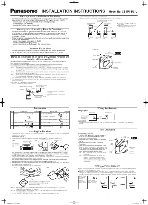
Customer Explanation
Give the Operating Instructions and this manual to the customer after finishing the installation. Use the Operating Instructions to explain to the customer how to use and care for the unit.
1
7 Cable clamp1 Nhomakorabea8 Clamp fixing screw
Quantity 2 1 2 1 1
Installing the Receiver
The receiver can only be installed on the corner indicated in Fig. A, so consider how the panel will face when it is installed on the indoor unit. 1 Remove the air inlet grill. 2 Remove the screw holding the adjustable corner cap, slide the cap to the side and remove it. (Fig. B)
If this packing is not put back, condensation may form on the wire, so it is absolutely necessary to put the sponge
packing back in place before continuing with the installation.
Codex R 10th 游戏台式机用户手册说明书
PrefacePreface1Overview2Getting Started3[Power Options] in Windows OS allow you to control the power managementSystem OperationsRight-click [Start]Select [Ethernet] and then [Network and Sharing Center]�Select [Set up a new connection or network]�Type the information from your Internet Service Provider (ISP) and click [Connect] to establish your LAN connection�Go to [Start]A list of available WLAN connections pops up� Choose a connection from the list�A new WLAN connection has been made�System OperationsGo to [Start]Select [Recovery] and click [Get started] under [Reset this PC] to start the system The [Choose an option] screen pops up. Choose between [Keep my files] [Remove everything]�Reset this PC Keep my filesRemove everythingOnly the drive whereWindows is installedJust remove my filesRemove files and clean the driveAll drivesJust remove my filesRemove files and clean the driveSystem Operations The [Your apps will be removed] screen shows a list of apps that will need to be reinstalled from the web or installation discs� Click [Next] to continue�The next screen will show the changes to be made during the process� Click [Reset] to start the system reset�If you have multiple hard drives, a screen will pop up, asking you to choose between [Only the drive where Windows is installed] and [All drives]�Then select between [Just remove my files] and [Remove files and clean the drive]. The next screen will show the changes to be made during the process� Click [Reset] to start the system reset�。
HOBBYWING 无线遥控车型系统使用声明说明书

********USER MANUALMulti-RotorXRotor Micro 45A BLHeli_32 4in1 DShot1200Brushless Electronic Speed Controller0103Features04Specifications05User GuideThrottle Range Calibration3Once1. Power up:Once2. Throttle signal detected (arming sequence start):While measuring3. When throttle is above midstick (meauring max throttle):While measuring5. When throttle is below midstick (measuring min throttle):Once4. If throttle is above midstick for 3 seconds:This beep sequence indicates that max throttle has been storedOnce6. If throttle is below midstick for 3 seconds :This beep sequence indicates that min throttle has been storedAt this point throttle calibration values are stored. You may remove power from the ESC, or just continue running your ESC.Once7. Throttle up detected (arming sequence start):Once8. Zero throttle detected (arming sequence end):06Programming parameters07OthersNormal Start-up Process2After this, the motor will run.Definitions for Different Ports110V: 10V Power output port .(For VTx , Camera , 12V LED light and etc .)BAT: Battery Volt monitoring port with the battery voltage is to connect to the Battery Volt monitoring port on flight controller.CTR: Amp monitoring port with the amperage of 15.2mv/A is to connect to the Amp monitoring port on flight controller.GND: Ground wire ;5V: 5V Power output port . (For FC , Camera , 5V LED light and etc .)S1-4: Throttle Signal Input Ports. Port S1 is for ESC M1, S2 is for M2, S3 is for M3, and S4 is for M4.POWER INPUT:Power input soldering point , “-” for connecting the power wire - , “+” for connecting the power wire + .Although there are some protections, improper use may still cause permanent damage to the product.• Always disconnect and remove batteries after use, as the ESC may drive the motor to rotate and cause unpredictable danger if it`s still connected to the battery. Long-time contact will cause the battery to completely discharge and result in damage to the battery or/and the ESC. This will not be covered under warranty.• The open source ESC can only be flashed with the corresponding firmware (not any other firmware) when flashing or upgrading firmware, otherwise it may cause the ESC to stop working or even damage the chip inside.• This user manual is based on the operation manual for BLHeli_32 ARM rev32.x and only for reference. For more detailed information, please refer to the original BLHeli manual. Due to firmware update or other reasons, the descriptions for functions may differ, so please always take the official BLHeli manual as standard.• High performance 32-bit microprocessor with the running frequency of up to 48MHz for excellent performance. • BLHeli_32 firmware is the third generation BLHeli, following base BLHeli and BLHeli-S.• All codes use damped light mode. Damped light does regenerative braking, causing very fast motor retardation, and inherently also does active freewheeling.• The code supports features to prevent sync loss. There are tunable parameters that can make the code run well even in the most demanding situations, although default settings will work excellently in normal operating environments.• The code supports regular 1-2ms pulse width input, as well as Oneshot125 (125-250us), Oneshot42 (41.7-83.3us) and Multishot (5-25us). • Dshot signaling is supported at any rate up to at least Dshot1200. The input signal is automatically detected by the ESC upon power up.• The code also supports a beacon functionality, where the ESC will start beeping after a given time of zero throttle. This can be very useful for finding lost crafts.• On board 10V &5V BEC , powering different accessories such as FC , VTx ,Camera and LED lights and etc.1. Rampup Power:Rampup power can be set to relative values from 3% to 150%. This is the maximum power that is allowed when ramping up at low RPMs and during start-up. For low RPMs, themaximum power to the motor is limited, in order to facilitate detection of low BEMF voltages. Rampup power also affects bidirectional operation, as the parameter is used to limit the power applied during direction reversal. During startup, the actual applied power depends on throttle input, and can be lower than the maximum level set by the rampup power parameter, but the minimum level is a quarter of the maximum level.2. Temperature Protection:Temperature protection can be enabled or disabled. And the temperature threshold can be programmed. The programmable threshold is primarily meant as a support for hardware manufacturers to use, as different hardware can have different tolerances on the max temperatures of the various components used. 3. Low RPM Power Protection:Power limiting for low RPMs can be enabled or disabled. Disabling it can be necessary in order to achieve full power on some low KV motors running on a low supply voltage. However, disabling it increases the risk of sync loss, with the possibility of toasting motor or ESC. 4. Low Voltage Protection:Low voltage protection can be set between 2.5V and 4.0V per LiPo cell. Or it can be disabled. When enabled, it will limit power applied to the motor if the battery voltage drops below the programmed threshold. This feature is primarily intended for fixed wing crafts. 5. Current Protection:Current protection can be enabled to limit current. If enabled, then current will be limited to maximum the programmed value. The reaction time of the current limiting is quite fast, so current will also be limited during accelerations.The value given for current protection, is per ESC. So if setting limit to e.g. 40A for each of the ESCs in a quad (using BLHeliSuite32), then the total current limit for the four ESCs will be 160A.6. Motor Direction:Motor direction can be set to fwd / rev / bidirectional / bidirectional rev.In bidirectional mode, center throttle is zero and above is fwd rotation and below is reverse rotation. When bidirectional operation is selected, throttle calibration is disabled. 7. Demag Compensation:Demag compensation is a feature to protect from motor stalls caused by long winding demagnetization time after commutation. The typical symptom is motor stop or stutter upon quick throttle increase, particularly when running at a low RPM. As mentioned above, setting high commutation timing normally helps, but at the cost of efficiency. Demag compensation is an alternative way of combating the issue. First of all, it detects when a demag situation occurs. • In this situation, there is no info on motor timing, and commutation proceeds blindly with a predicted timing. • In addition to this, motor power is cut off some time before the next commutation.A metric is calculated that indicates how severe the demag situation is. The more severe the situation, the more power is cut off. When demag compensation is set to off, power is never cut.When setting it to low or high, power is cut. For a high setting, power is cut more aggressively. Generally, a higher value of the compensation parameter gives better protection.If demag compensation is set too high, maximum power can be somewhat reduced for some motors. 8. Motor Timing:Motor timing can be set between approximately 10 and approximately 310 in approximately 10 increments (actual accurate values here are 15/16ths of a degree).Typically a medium setting will work fine, but if the motor stutters it can be beneficial to increase timing. Some motors with high inductance can have a very long commutation demagnetization time. This can result in motor stop or stutter upon quick throttle increase, particularly when running at a low RPM. Setting timing higher will allow more time for demagnetization, and often helps.This parameter can also be set to auto. In this case the code monitors demagnetization time, and keeps timing as low as possible without having issues with demag. On well behaved motors, timing can be low in the entire power range, and thereby max power can be reduced. On not so well behaved motors, timing is increased as needed, and thereby improves margins against sync loss. 9. Maximum Acceleration:Maximum acceleration can be set between 0.1%/ms and 25.5%/ms. It can also be set to maximum, in which case acceleration is not limited. Limiting acceleration is primarily intended as a backup parameter that can be used in cases where too hard acceleration gives desyncs.When setting to e.g. 10%/ms, it means that the power applied to the motor is not allowed to increase by more than 10% per millisecond. 10. Throttle Cal Enable:If disabled, throttle calibration is disabled.11. Minimum Throttle, Maximum Throttle and Center Throttle:These settings set the throttle range of the ESC. Center throttle is only used for bidirectional operation. The values given for these settings are for a normal 1000us to 2000us input signal, and for the other input signals, the values must be scaled. For Dshot input signal, these settings have no effect. 12. Brake On Stop:Brake on stop can be set between 1% and 100%, or disabled. When not disabled, the given brake force will be applied when throttle is zero. For nonzero throttle, this setting has no effect. This feature is primarily intended for fixed wing crafts with folding props.On some ESCs this setting is not linearly programmable, it will just be enabled (at 100% force for any setting 1%-100%) or disabled (this applies to ESCs that have “EN/PWM” style fet drivers). 13. LED Control:LEDs can be controlled on ESCs that support it. Up to 4 LEDs can be turned on or off. 14. Beep Strength:Sets the strength of beeps under normal operation. 15. Beacon Strength:Sets the strength of beeps when beeping beacon beeps. The ESC will start beeping beacon beeps if the throttle signal has been zero for a given time. Note that setting a high beacon strength can cause hot motors or ESCs! 16. Beacon Delay:Beacon delay sets the delay before beacon beeping starts. 17. PWM frequency:Motor PWM frequency can be programmed between 16kHz and 48kHz. Higher PWM frequency can run motors smoother. Programmable frequency also allows for moving of small but potentially disturbing bumps in the throttle response. All ESCs have these bumps, with BLHeli_32 they can be moved in the RPM range, to a place where the system has low sensitivity to them.1. Thermal ProtectionThe ESC measures temperature within the MCU and limits motor power if the temperature is too high. Motor power is limited over a range: • If the temperature is above the threshold, motor power begins to be limited.• If the temperature is above the threshold plus approximately 150℃, motor power is limited to 25%. Motor power is not limited below 25%. 2. Stall ProtectionIf the motor has attempted to start but not succeeded for a few seconds, it will stop attempting and wait for throttle to be zeroed before attempting again. 3. Beacon---BeepsIf the ESC is armed and sees zero throttle for a given time, it beeps beacon beeps, which are approximately one beep per three seconds.4. Not activated ESC---BeepsAll ESCs shall be activated during manufacturing. If for some reason this is not done, the ESC will beep like this upon power up, before the normal operation beep sequence starts: “B, B, B… (the time interval shortens gradually)”. If for some reason activation has failed and the ESC is not regarded as a valid BLHeli_32 unit, the ESC will beep like this upon power up, before the normal operation beep sequence starts: “BBB, BBB, BBB…(the tone of the “BBB” changes from high to low)”. In this case the ESC will only accept 1-2ms pwm input signal. 5. Other Relevant InformationBLHeli official website: https:///bitdump/BLHeliBLHeli32 official documentation download website: https:///bitdump/BLHeli/tree/master/BLHeli_32%20ARM Firmware: Hobbywing_XRotor_BLHeli32...。
SDX-2P超长距离HDBaseT双DVI-D、双RS232、音频、USB键盘和鼠标扩展器说明书

SDX-2P-TX Back
SDX-2P-RX Front
SDX-2P-RX Back
11651 Vanowen St. North Hollywood, CA 91605
SDX-2P
SUPER RANGE HDBaseT DUAL DVI-D, DUAL
RS232, AUDIO AND USB KEYBOARD AND MOUSE
EXTENDER
EXTEND DUAL DVI-D, DUAL RS232, USB KEYBOARD, MOUSE AND AUDIO UP TO 400 FEET OVER DUAL CAT5/5E/6 CABLE
The SDX-2P also has USB keyboard and mouse, audio and RS232 extension, giving you the ability to control your displays or devices remotely.
FEATURES
Extends dual DVI-D up to 400 feet (120m) from the source
(2) DVI-D Single Link 165 MHz (2) DVI-D 29-pin (Female) (2) DVI-D 29-pin (Female) Up to 1920 x 1200 @60Hz 5 volts p-p(TTL) Automatic Up to 20 ft. Up to 20 ft.
port on the SDX-2P-TX. 4. Optionally connect RS232 for control functions. 5. Connect the SDX-2P-TX to the SDX-2P-RX with
- 1、下载文档前请自行甄别文档内容的完整性,平台不提供额外的编辑、内容补充、找答案等附加服务。
- 2、"仅部分预览"的文档,不可在线预览部分如存在完整性等问题,可反馈申请退款(可完整预览的文档不适用该条件!)。
- 3、如文档侵犯您的权益,请联系客服反馈,我们会尽快为您处理(人工客服工作时间:9:00-18:30)。
遥控玩具专用单芯片解决集成控制器
目 录
概述.............................................................................................................- 3 - 引脚功能描述..............................................................................................- 4 -
功能描述.................................................................................- 4 -
应用范例.....................................................................................................- 6 - 极限参数.....................................................................................................- 7 - 电气参数.....................................................................................................- 7 - 封装数据.....................................................................................................- 7 - 丝印说明.....................................................................................................- 8 -
DRX-2P10
DRX-2P10
概述:
DRX-2P10是为遥控汽车等玩具设计的专用单芯片解决方案,将传统的接收芯片+片
外功率驱动的方案替代为接收+驱动单芯片方案,降低器件外围成本,提高可靠性。
适用于2~3节电池应用。
该芯片具有较大的电流驱动能力;内置箝位二极管可释放感性负
载的反向冲击电流,可安全可靠用于电机驱动中。
过温保护进一步增强了系统的可靠性。
特点:
与TX-2S 搭配实现精简的遥控汽车解决方案
宽工作电压范围(VDD=2.0V~5V,推荐应用在2~3节电池应用中); 内置2路全桥驱动(动力电机,转向电机),驱动能力可达1A; 完全的可操控性(前进、后退、加速、转向); 带有过流保护和过温保护;
低导通电阻的功率管(典型情况下NMOS 和PMOS 有源区电阻之和为0.4欧姆)
功能框图:
图
1. 功能框图
DRX-2P10DRX-2P10
脚位功能描述:
表1. 遥控+马达驱动的管脚描述
1 VO
2 用于信号放大的反相器2输出端
2 SI 编码信号输入端
3 OSCI 振荡器电阻输入端
4 AGND 控制部分电源地
5 VM2 左转右转马达2的输入电源
6 左转OUT2A 左转右转马达2输出A端
7 右转OUT2B 左转右转马达2输出B端
8 GND2 左转右转马达2的地
9 GND1 前进后退马达1的地
10 后退OUT1B 前进后退马达1输出B端
11 前进OUT1A 前进后退马达1输出A端
12 VM1 前进后退马达1的输入电源
13 VDD 控制部分电源正端
14 VI1 用于信号放大的反相器1输入端
15 VO1 用于信号放大的反相器1输出端
16 VI2 用于信号放大的反相器2输入端
功能描述
过温保护
当结温高于150°C时进入待机状态,不接受指令,直到温度降低到135°C,恢复正常工作,指令到达后动作。
解码频率
采用经典的RC驰裕型振荡器,在做好温度补偿基础上,采用Trimming电阻方式达到指标。
时序说明(参考TX-2B与RX-2B):
图3. 编码时序—位编码格式
图4. 编码时序—字编码格式
图5. 解码时序
应用范例
应用电路图
图6. RF 遥控+电机驱动(电动车或者遥控玩具)
DRX-2P10
图7. 红外遥控+驱动(电动车或者遥控玩具)
DRX-2P10
极限参数
表2. 绝对最大额定值(TA=25°C)
参数符号值单位最大控制电源电压 VDD(MAX) 5.5 V 输入输出电压 VIN/VOUT GND-0.3~VDD+0.3 V 最大外加输出电压 VOUT(MAX) VDD V 每通道最大输出电流(峰值)注IOUT(MAX) 1 A ESD能力(人体模型) 3000 V
电气特性
表3. 电特性参数表(测试条件VDD=4.5V,TA=25°C)
参数符号最小典型最大单位
电源电压 VDD 2.2
- 5.0 V 静态电流 IQ
- 300-μA
OUT1功率管NMOS+PMOS导通电阻(ACTIVE) R ON1- 0.3
- Ohm
OUT2功率管NMOS+PMOS导
通电阻(ACTIVE)
R ON2 0.4 Ohm
过温保护 TP
- 150-℃
过温保护滞回- 10
-℃
解码频率(REXT=250k)FOSC 123 128 133 kHz
振荡器温度系数 COSC 300
ppm 逻辑高电平 VINH 2.0
-- V
逻辑低电平 VINL-- 0.8 V
遥控玩具专用单芯片解决集成控制器
封装数据
DRX-2P10
汉微电子科技有限公司
QQ:530539988 MAIL:530539988@。
