RD130EB中文资料
爱达顿电源分发单元G3 EMIB05系列说明说明书

Eaton EMIB05Eaton Metered Input rack PDU, 0U, 26U, Input IEC-60309 32A 1Ph, 7.4 kW max, 32A, 200-240V, Outlets 20XC13 : 4XC19General specificationsEaton metered input rack PDU EMIB057431720659021150 mm 52 mm 53 mm 4 kg 2 year CE Marked RoHS Compliant EAC CEIEC 60950-1 EN 55024:2010EPDU MI 0U (309 32A 1P)20XC13:4XC19Product NameCatalog Number UPCProduct Length/Depth Product Height Product Width Product Weight Warranty Compliances Certifications Model Code20Single-phase Connecting cord with plug Metric7.4 kW max0U (Vertical)Vertical32 AIEC-60309 32A 1PhDisplayAmpere Meter Mounting material50/60 Hz0° to 60°C (32° to 140°F) Yes Eaton ePDU G3 one-page overviewEaton ePDU G3 brochureEaton UPS Services Quick Guide 2021Eaton UPS and battery servicesEaton ePDU G3 - BrochureEaton RoHS Declaration of Conformity: ePDU G3EU Declaration of Conformity Eaton ePDUs G3Drawing EMIB05Eaton ePDU G3 EMP installation and connection quick start guide Eaton ePDU G3 operations manualEaton ePDU G3 replace and configure eNMC moduleEaton ePDU G3 - Installation and Connectivity Quick StartEaton ePDU G3 installation and connectivity quick start guide Eaton Double-wide G3 ePDU installation and connectivity quick start guideEaton ePDU G3 1U and 2U installation addendumEaton ePDU G3 instruction set - system objectsOptimizing rack power distributionQuick guide to power distributionNumber of Outputs C13PhaseElectrical connectionMounting dimension (standardized) WattageForm factorMounting directionAmperage RatingPackage contentsInput connectionFitted with:Frequency ratingOperating TemperatureEthernet interface BrochuresCertification reports Compliance information DrawingsManuals and user guides White papersRack PDUMounting accessories Network cable Configuration cable Splitter for daisy-chaining Quickstart guideSafety InstructionsNumber of outlets with earth pin24Circuit breaker(2) single-poleMass configurationYesCommunicationHTTP, HTTPS, SSL, Telnet, FTP, SNMP, SMTP, DNS, DHCP, LDAP, RADIUSSpecial featuresPhase Metering, CircuitBreaker Current Meteringand Input MeteringHot-Swap Control modulewith advanced LCDOptionalTemperature/HumiditysensorBuilt-in IEC outlet eGripretention, retains allstandard IEC plugsBuilt-in outlet P-lock system,locking mechanism with P-lock power cordsDaisy-Chain up to 8 PDUs,reduce networkinfratsructure costsPower chain monitoring &Real time Intelligence onyour Data Center, via EatonIntelligent Power Manager60°C Operating temperatureColour-coded outlet andbranch circuits for simpleload balancingHydraulic–Magnetic CircuitBreakers with accidental tripprotectionNumber of Outputs C194Outlet controlNoSwitchableEaton Corporation plc Eaton House30 Pembroke Road Dublin 4, Ireland © 2023 Eaton. All rights reserved. Eaton is a registered trademark.All other trademarks areproperty of their respectiveowners./socialmediaNo 3m200-240V Black Yes Aluminium2(20) C13, (4) C19Rack PDU Yes52Cord length Input voltage Color SNMP Material Over voltage category OutletsType Serial interface Mounting Dimension (metrical)。
调速器硬件手册

ETD 790直流调速器
页码:2 /86
ETD 790直流调速器 电流预测控制
6.4e 模拟输出 .............................................................................................................. 39 6.4f 422/485串行口....................................................................................................... 41 6.4g 直流测速电机反馈接线 ......................................................................................... 42 6.4h 用于指示输入和输出的LED指示器 ....................................................................... 43 6.5 RS 232、CAN总线、编码器1、编码器2的连接器....................................................
欧洲电器大型电磁铁产品说明书

Dimensions: [mm]Scale - 1:17443640470744364047074436404707443640470T e m p e r a t u r eT pT L7443640470Further informationComponent Libraries:Altium_WE-HCF (23a)Downloads_CADENCE_WE-HCF (23a)Download_CadStar_WE-HCF (20a)Eagle_WE-HCF (23a)Download_IGS_WE-HCF_2818PSpice_WE-HCF (22a)Download_STP_WE-HCF-2818Spectre_WE-HCF (23a)Free Sample Order:Order free samples of this article directly here!Tutorials:■Single Coil Inductors (PDF)■Redefining Rated Current Measurements for Power Inductors (PDF)REDEXPERT:Calculate losses for 7443640470 in REDEXPERTWürth Elektronik eiSos GmbH & Co. KGEMC & Inductive SolutionsMax-Eyth-Str. 174638 WaldenburgGermanyCHECKED REVISION DATE (YYYY-MM-DD)GENERAL TOLERANCE PROJECTIONMETHODALa005.0012023-11-30DIN ISO 2768-1mDESCRIPTIONWE-HCF SMT High CurrentInductor ORDER CODE7443640470SIZE/TYPE BUSINESS UNIT STATUS PAGECautions and Warnings:The following conditions apply to all goods within the product series of WE-HCF of Würth Elektronik eiSos GmbH & Co. KG:General:•This electronic component was designed and manufactured for use in general electronic equipment.•Würth Elektronik must be asked for written approval (following the PPAP procedure) before incorporating the components into any equipment in fields such as military, aerospace, aviation, nuclear control, submarine, transportation (automotive control, train control, ship control), transportation signal, disaster prevention, medical, public information network, etc. where higher safety and reliability are especially required and/or if there is the possibility of direct damage or human injury.•Electronic components that will be used in safety-critical or high-reliability applications, should be pre-evaluated by the customer. •The component was designed and manufactured to be used within the datasheet specified values. If the usage and operation conditions specified in the datasheet are not met, the wire insulation may be damaged or dissolved.•Do not drop or impact the components, as the core may flake apart.•Würth Elektronik products are qualified according to international standards, which are listed in each product reliability report. Würth Elektronik does not guarantee any customer qualified product characteristics beyond Würth Elektroniks’ specifications, for its validity and sustainability over time.•The customer is responsible for the functionality of their own products. All technical specifications for standard products also apply to customer specific products.Product specific:Soldering:•The solder profile must comply with the Würth Elektronik technical soldering specification. All other profiles will void the warranty. •All other soldering methods are at the customers’ own risk.Cleaning and Washing:•Washing agents used during the production to clean the customer application may damage or change the characteristics of the wire insulation, marking or plating. Washing agents may have a negative effect on the long-term functionality of the product. Potting:•If the product is potted in the costumer application, the potting material may shrink or expand during and after hardening. Shrinking could lead to an incomplete seal, allowing contaminants into the core. Expansion could damage the core or wire contacts. Werecommend a manual inspection after potting to avoid these effects. Storage Conditions:• A storage of Würth Elektronik products for longer than 12 months is not recommended. Within other effects, the terminals may suffer degradation, resulting in bad solderability. Therefore, all products shall be used within the period of 12 months based on the day of shipment.•Do not expose the components to direct sunlight.•The storage conditions in the original packaging are defined according to DIN EN 61760-2.Packaging:•The packaging specifications apply only to purchase orders comprising whole packaging units. If the ordered quantity exceeds or is lower than the specified packaging unit, packaging in accordance with the packaging specifications cannot be ensured. Handling:•Violation of the technical product specifications such as exceeding the nominal rated current will void the warranty•Applying currents with audio-frequency signals may result in audible noise due to the magnetostrictive material properties. •Due to heavy weight of the components, strong forces and high accelerations may have the effect to damage the electrical connection or to harm the circuit board and will void the warranty.These cautions and warnings comply with the state of the scientific and technical knowledge and are believed to be accurate and reliable.However, no responsibility is assumed for inaccuracies or incompletenessWürth Elektronik eiSos GmbH & Co. KGEMC & Inductive SolutionsMax-Eyth-Str. 174638 WaldenburgGermanyCHECKED REVISION DATE (YYYY-MM-DD)GENERAL TOLERANCE PROJECTIONMETHODALa005.0012023-11-30DIN ISO 2768-1mDESCRIPTIONWE-HCF SMT High CurrentInductor ORDER CODE7443640470SIZE/TYPE BUSINESS UNIT STATUS PAGEImportant NotesThe following conditions apply to all goods within the product range of Würth Elektronik eiSos GmbH & Co. KG:1. General Customer ResponsibilitySome goods within the product range of Würth Elektronik eiSos GmbH & Co. KG contain statements regarding general suitability for certain application areas. These statements about suitability are based on our knowledge and experience of typical requirements concerning the areas, serve as general guidance and cannot be estimated as binding statements about the suitability for a customer application. The responsibility for the applicability and use in a particular customer design is always solely within the authority of the customer. Due to this fact it is up to the customer to evaluate, where appropriate to investigate and decide whether the device with the specific product characteristics described in the product specification is valid and suitable for the respective customer application or not.2. Customer Responsibility related to Specific, in particular Safety-Relevant ApplicationsIt has to be clearly pointed out that the possibility of a malfunction of electronic components or failure before the end of the usual lifetime cannot be completely eliminated in the current state of the art, even if the products are operated within the range of the specifications.In certain customer applications requiring a very high level of safety and especially in customer applications in which the malfunction or failure of an electronic component could endanger human life or health it must be ensured by most advanced technological aid of suitable design of the customer application that no injury or damage is caused to third parties in the event of malfunction or failure of an electronic component. Therefore, customer is cautioned to verify that data sheets are current before placing orders. The current data sheets can be downloaded at .3. Best Care and AttentionAny product-specific notes, cautions and warnings must be strictly observed. Any disregard will result in the loss of warranty.4. Customer Support for Product SpecificationsSome products within the product range may contain substances which are subject to restrictions in certain jurisdictions in order to serve specific technical requirements. Necessary information is available on request. In this case the field sales engineer or the internal sales person in charge should be contacted who will be happy to support in this matter.5. Product R&DDue to constant product improvement product specifications may change from time to time. As a standard reporting procedure of the Product Change Notification (PCN) according to the JEDEC-Standard inform about minor and major changes. In case of further queries regarding the PCN, the field sales engineer or the internal sales person in charge should be contacted. The basic responsibility of the customer as per Section 1 and 2 remains unaffected.6. Product Life CycleDue to technical progress and economical evaluation we also reserve the right to discontinue production and delivery of products. As a standard reporting procedure of the Product Termination Notification (PTN) according to the JEDEC-Standard we will inform at an early stage about inevitable product discontinuance. According to this we cannot guarantee that all products within our product range will always be available. Therefore it needs to be verified with the field sales engineer or the internal sales person in charge about the current product availability expectancy before or when the product for application design-in disposal is considered. The approach named above does not apply in the case of individual agreements deviating from the foregoing for customer-specific products.7. Property RightsAll the rights for contractual products produced by Würth Elektronik eiSos GmbH & Co. KG on the basis of ideas, development contracts as well as models or templates that are subject to copyright, patent or commercial protection supplied to the customer will remain with Würth Elektronik eiSos GmbH & Co. KG. Würth Elektronik eiSos GmbH & Co. KG does not warrant or represent that any license, either expressed or implied, is granted under any patent right, copyright, mask work right, or other intellectual property right relating to any combination, application, or process in which Würth Elektronik eiSos GmbH & Co. KG components or services are used.8. General Terms and ConditionsUnless otherwise agreed in individual contracts, all orders are subject to the current version of the “General Terms and Conditions of Würth Elektronik eiSos Group”, last version available at .Würth Elektronik eiSos GmbH & Co. KGEMC & Inductive SolutionsMax-Eyth-Str. 174638 WaldenburgGermanyCHECKED REVISION DATE (YYYY-MM-DD)GENERAL TOLERANCE PROJECTIONMETHODALa005.0012023-11-30DIN ISO 2768-1mDESCRIPTIONWE-HCF SMT High CurrentInductor ORDER CODE7443640470SIZE/TYPE BUSINESS UNIT STATUS PAGE。
RD系列电力智能高频开关电源模块使用手册(三相)(精)
RD10(20A230(115C整流模块§1 模块功能特点●LCD 汉字显示,模块工作状态和工作参数一目了然,在系统主监控工作时,模块接收主监控发出的工作参数,无主监控器时,可以在模块面板上方便的设置模块工作参数,模块可脱离主监控器工作。
●RD 系列整流模块可充当便携式充电机使用 , 整流模块本身可设定均充电压 , 均充时间 , 转换电流 , 转换时间 , 浮充电压 , 浮充时间等参数 , 设置完成后充电模块可独立完成对蓄电池组的充电过程 (无需监控 , 并且在充电过程中能根据充电电流值大小自动完成均浮充状态的转换 , 从而保证了电池组充电时的安全和快捷 . 多充电模块在无监控系统并机运行时 , 只需在其中一个模块上设置运行参数 , 其它充电模块无需单独设置即可按照该模块的运行参数同步运行 , 使用方便 .●软件校准技术:传统模块参数整定都采用电位器整定,但存在固有缺陷,如电位器漂移问题以及现场调整不便等问题; 我公司生产的 RD10(20A230(115C模块采用软件校准技术,模块内部没有一个电位器,通过按键和 LCD 显示可以校准模块输出电压、输出限流、电压测量、电流测量;模块参数调整方便快捷。
●自主均流技术:模块采用自主均流技术,模块间电流偏差小于 3%;●ZVS 软开关技术:为了使开关电源能够在高频下高效率地运行, 我公司不断研究开发高频软开关技术,已开发成功 ZVS 边缘谐振技术,使开关过程损耗大为降低,从而进一步减小体积、减轻重量、极大提高模块性能。
1.1 ZVS软开关优点✧开关损耗小✧可实现高频化(极限頻率可做到 1-2MHz 、开关过程在平滑状态下实现✧恒频运行,谐波成份小✧无吸收电路✧电流、电压应力小1.2 ZVS软开关基本原理硬开关过程和软开关开关过程比较如下图。
功率 MOSFET 损耗由三部分组成:开通损耗、关断损耗和导通损耗组成,硬开关在开关过程中电压和电流同时变化,即存在高压大电流的状态,此时损耗很大,一般需要加吸收电路减小开关损耗,同时在关断过程中, VDS 会出现过冲,对功率管有较大的损害。
全能电子IS130系列无管理层2交换机产品说明说明书

Allied Telesis ruggedized IS130 industrial unmanaged switches provide enduring performance in harsh environments, such as those found in outdoor IoT and industrial applications.OverviewThe Allied Telesis IS130 multipurpose unmanaged Layer 2 switches are ideal for Smart Cities applications, harsh industrial environments, and any situation where tough and reliable devices are required.With a wide operating temperature range of between -40°and 75°C, the IS130 switches tolerate demanding environments, such as those found in industrial and outdoor deployments. PerformanceThese high-performing,cost-effective switches meet the stringent performance requirements of today’s industrial networks. Featuring support for up to 2K MAC addresses, the IS130 Series is ideal for edge networking.Gigabit and Fast EthernetThe IS130 Series SFP port supports both Gigabit and Fast Ethernet Small Form-Factor Pluggables (SFPs). This makes the IS130 Series ideal for environments where Gigabit fiber will be phased-in over time, and allows for uninterrupted connectivity to the legacy 100FX hardware while it is upgraded to Gigabit Ethernet. Support for both SFP speeds allows organizations to stay within budget as they migrate to faster technologies.Power over EthernetThe IS130-6GP is a Power over Ethernet Power Sourcing Equipment (PoE PSE) device, which is compliant with IEEE802.3af and IEEE802.3at standards.Each port supplies either 15.40W PoE with 12.95W available to the powered device, or 30.00W PoE+ with 25.50W available to the powered device.PoE sourcing is the ideal solution to support many devices, including1:ۼPan, Tilt and Zoom (PTZ) cameras with heating/cooling fans foroutdoor applicationsۼEnhanced infrared lightingۼLighting controllersۼLED lighting fixturesۼRemote Point of Sale (POS) kiosks1Power supply must be compliant with local/national safety and electrical code requirements. Select the supply with the most appropriate output power derating curve.IS130 SeriesIndustrial Unmanaged Layer 2 SwitchesIndustrial Switches | Product InformationKey FeaturesۼFull Gigabit, wirespeed portsۼ100/1000Mbps SFP supportۼIEEE 802.3at PoE+ sourcing (30W)ۼ90W PoE power budgetۼWide -40 to +75°C operatingtemperature rangeۼDual power inputs with reversepolarity and over-current protectionۼAlarm outputۼDIN rail and wall mountۼIP-30 (metal case)617-000642 Rev CPower CharacteristicsPhysical SpecificationsStandards and ProtocolsEthernetIEEE 802.2 Logical Link Control (LLC)IEEE 802.3 Ethernet IEEE 802.3ab 1000BASE-TIEEE 802.3afPower over Ethernet (PoE)SpecificationsPerformanceۼUp to 2K MAC addresses ۼPacket buffer memory: 128KBۼSupports 9,216 bytes jumbo framesOther Interfaces ۼType Alarm output (1A @ 24Vdc)Port no. 1Connector 2-pin Terminal Block 2ۼType Power Input Port no. 2Connector 2-pin Terminal Block 2Environmental Specifications ۼOperating temperature range: -40°C to 75°C (-40°F to 167°F) ۼStorage temperature range: -40°C to 85°C (-40°F to 185°F) ۼOperating relative humidity range: 10% to 95%RH non-condensing ۼStorage relative humidity range: 10% to 95%RH non-condensing ۼOperating altitude3,000m maximum (9,843 ft)MechanicalۼEN 50022, EN 60715 Standardized mounting on rails Environmental Compliance ۼRoHSۼChina RoHS ۼWEEE*sourcing IEEE 802.3af Type 1 (PoE) ** sourcing IEEE 802.3at Type 2 (PoE+)2A single 6-pin screw Terminal Block include both powerinput and alarm outputIEEE 802.3at Power over Ethernet plus (PoE+) IEEE 802.3u 100BASE-XIEEE 802.3x Flow control (FDX)IEEE 802.3z1000BASE-X*** The Max Power consumption at full PoE load includes PD’s consumption and margin. Thecooling requirements of the switch are smaller than the power draw, because most of the load is dissipated at the PoE powered device (PD) and along the cabling. Use these wattage and BTU ratings for facility capacity planning.Ordering InformationSwitchesThe DIN rail and wall mount kits are included.AT-IS130-6GP-80Industrial un-managed Layer 2 Switch,PoE+ supportSupported SFP ModulesRefer to the installation guide for the recommended Max. Operating Temperature according to the selected SFP module.100Mbps SFP ModulesAT-SPFX/2100FX multi-mode 1310 nm fiber up to 2 km AT-SPFX/15100FX single-mode 1310 nm fiber up to 15 km AT-SPFXBD-LC-13100BX Bi-Di (1310 nm Tx, 1550 nm Rx) fiber up to 10 kmAT-SPFXBD-LC-15100BX Bi-Di (1550 nm Tx, 1310nm Rx) fiber up to 10 km1000Mbps SFP ModulesAT-SPSX1000SX GbE multi-mode 850 nm fiber up to 550 m AT-SPSX/I1000SX GbE multi-mode 850 nm fiber up to 550 m industrial temperatureAT-SPEX1000X GbE multi-mode 1310 nm fiber up to 2 km AT-SPLX101000LX GbE single-mode 1310 nm fiber up to 10 kmAT-SPLXI0/I1000LX GbE single-mode 1310 nm fiber up to 10 km industrial temperatureAT-SPLX401000LX GbE single-mode 1310 nm fiber up to40 kmAT-SPBDI0-131000BX GbE Bi-Di (1310 nm Tx, 1490 nm Rx) fiber up to 10 kmAT-SPBDI0-141000BX GbE Bi-Di (1490 nm Tx, 1310 nm Rx) fiber up to 10 kmAT-SPBD20-13/I1000BX GbE Bi-Di (1310 nm Tx, 1490 nm Rx) fiber up to 20 km, industrial temperatureAT-SPBD20-14/I1000BX GbE Bi-Di (1490 nm Tx, 1310 nm Rx) fiber up to 20 km, industrial temperatureAT-SPBD40-13/I1000BX GbE Bi-Di (1310 nm Tx, 1490 nm Rx) fiber up to 40 km, industrial temperatureAT-SPBD40-14/I1000BX GbE Bi-Di (1490 nm Tx, 1310 nm Rx) fiber up to 40 km, industrial temperaturePanel Cut-out Dimensions: 30 x 140 x 95 mm (1.18 x 5.51 x 3.74 in)。
杜维电气电能表说明书

杜维电气电能表说明书
产品参数:
名称:杜维电气电能表
品牌:杜维
正常工作电压:0.85Un~1.15Un
极限工作电压:0.7Un~1.2Un
电压线路功耗:≤1.ow和5VA
电流线路功耗:≤1VA
备份电池电压:3.6VDC
产品概述:
杜维电气电能表由单相电子式电能表单元和费率单元组成, LCD 显示,有红外或通信功能。
该表具有测量精度高、稳定性好、过载能力强、可靠性高等显著优点。
可为单相分时计费提供先进、可靠的计量工具。
产品原理:
杜维电气电能表主要由A/D转换、功率计算、电能累加、防潜动等部分组成。
具有高可靠、高精度、低功耗的特点。
电能表采用变压器供电方式。
杜维电气电能表分别将电能分别转换为脉冲,再由芯片完成电量脉冲采集,电量累计,完成红外抄表、LCD 显示功能处理等
功能。
美国特色商品说明书:高效热风梆风干器说明(115-120V)-上位置安装

Scan for InformationP roduct o verviewAmerican Specialties, Inc. | 441 Saw Mill River Road, Yonkers, NY 10701 | (914) 476-9000 | Model:#0199-1Issued:11/1/2021Revised:8/22/2023Page:1 of 2Revision :R3s ustainability /leedTURBO ADA™ HIGH-SPEED Hand Dryer (115-120V) – Surface Mounted – White294Toilet Accessories CSI:10 28 13EAp2 (0) EA 1 (1-19)o Peration & M aintenancet echnical i nForMation / P roduct P roPertiesi nstallationo Ptionsw arrantySurface mount unit on wall with four (4) 1/4" [6] washers and screws or bolts (supplied) through holes (provided) in a corrosion protected steel back plate into suitable prepared mountings (by others) or other suitable mounting hardware (by others) to suit wall conditions. Electrical service is supplied and connected (by others) prior to installing cover. Cover is secured to back plate with recessed, pin-hex pan head cap screws (supplied) opened with security wrench (supplied). For compliance with ICC/ANSI A-117.1-2003 and 2010 ADA Accessibility Standards for adults install unit with bottom of sensor lens 48" [1219] maximum Above Finished Floor (AFF) if unobstructed reach access is provided or 44" [1118] max AFF if forward reach over an obstruction (e.g. vanity or commode) with reach depth greater than 20" [508] and less than 25" [635] is only provided. For general utility install unit so that sensor lens is 44" [1118] to 54" [1372] AFF . Mounting T emplate and Installation Guide (MT & IG) is supplied with unit.Voltage0199-1: 110-120 VAC - 50/60 Hz - 10.4 A (Max.) - 1000W 0199-2: 208-240 VAC - 50/60 Hz - 5.2 A (Max.) - 1000WMotorHPRPM (x1000)Fan T ypeAirflowHeating Element Air Output T emperatureTimingDrying Time Brush T ype Dual Ball Bearings0.6716-29 (Adj.)Multi-Inlet Centrifugal 63.6 CFM (108 m3/h)Nichrome wire with auto reset circuit breaker131o F ± 5@ 77o F (55o C ±2.8 @ 25o C) Ambient room tempAutomatic 60 second Shut-Off Less Than 15 SecondsManufacturer reserves the right to make changes to the design, dimensions or functionality of the product without formal notice.Automatic "No-Touch"Activate dryer by placing hands under sensor. LED in sensor array shines blue light during operation to guide user to optimal hand placement for shorter drying time. Dryer automatically shuts off after user removes hands from sensor zone. Complete OM and MT -IG are supplied with unit for future reference of Installation Requirements, Operating Conditions and Service.Five (5) Y ears from date of InvoiceAmerican Specialties, Inc. | 441 Saw Mill River Road, Yonkers, NY 10701 | (914) 476-9000 | Model:CSI:#0199-110 28 13Toilet Accessories Issued:11/1/2021Revised:8/22/2023Page:Revision :White Porcelain Enamel on Steel115-120V AC PropertyValueDimensions Construction 10-5/8" x 8-15/32" x 4" [270 x 215 x 102]Surface Mounted - "Touch Free" Operation 2 of 2R3Mounting Electrical。
RDC80系列旋转潜变电阻器说明书

Rotary PotentiometersSlide Potentiometers Metal Shaft Insulated Shaft Knob Operating Through Shaft Type Ring TypeThrough Shaft Type / Soldering ConditionsThrough Shaft Type / Product SpecificationsReference for Manual SolderingExample of Reflow Soldering ConditionSeries Tip temperature Soldering timeRDC80350±5℃ 3 s+11. Cleaning should not be attempted.2. Type of solder to be used Use cream solder that contains 10 to 15 %wt flux.3. Number of solder applications - apply solder only once4. Recommended reflow conditionsSeries A B C D E F G H I No. ofreflows RDC80250℃ー180℃150℃90±30sー10±1sーー 1 time1. When using an infrared reflow oven, solder may not always be applied as intended.Be sure to use a hot air reflow oven or a type that uses infrared rays in combination with hot air.2. The temperatures given above are the maximum temperatures at the terminals of the products when employing a hotair reflow method. The temperature of the PC board and the surface temperature of the products may vary greatly depending on the PC board material, its size and thickness. Ensure that the surface temperature of the products does not rise to 250℃or greater.3. Conditions vary to some extent depending on the type of reflow bath used. Be sure to give due consideration to this priorto use.NotesMethod for Regulating the LinearityModel RDC804T output2T output±3%±3%±165˚±165˚180˚ phase differenceOutputvoltageratio%2. The center is in the configuration diagram condition1. Reference taper : 100%/340˚100500˚centerI max.H max.300200100RoomtemperaturePre-heatingE max.Time sTemperature℃ABCDF max.G max.。
美国爱本电子(Eaton)产品说明书
Eaton PDG34FH400P2DJPower Defense Globally Rated, Frame 3, Four Pole, 400A-High, 25kA/480V, PXR25 LSI w/ Modbus RTU, CAM Link and Relays, Std Line Load Term (PDG3X4TA401H)Eaton Power Defense molded case circuit breakerPDG34FH400P2DJ 786679538265109.1 mm 257.1 mm 182.9 mm 7.68 kg Eaton Selling Policy 25-000, one (1) year from the date of installation of theProduct or eighteen (18) months from thedate of shipment of the Product,whichever occurs first.RoHS Compliant UL 489IEC 60947-2CCC MarkedCSAProduct NameCatalog Number UPCProduct Length/Depth Product Height Product Width Product Weight WarrantyCompliancesCertifications400A High Override Complete breaker 3Four-pole (100% N)PD3 GlobalClass APXR 25 LSIModbus RTU and CAM Link600 Vac600 V100% neutral protectionStandard Line and Load25 kAIC at 480 Vac35 kAIC @240V (UL) 10 kAIC Icu @250 Vdc Eaton Power Defense MCCB PDG34FH400P2DJ 3D drawingConsulting application guide - molded case circuit breakers Power Xpert Protection Manager x32Power Xpert Protection Manager x64StrandAble terminals product aidPower Defense technical selling bookletPower Defense molded case circuit breaker selection poster Power Defense brochureMolded case circuit breakers catalogAmperage RatingCircuit breaker frame type FrameNumber of poles Circuit breaker type ClassTrip Type CommunicationVoltage ratingVoltage rating - maxProtectionTerminalsInterrupt rating Interrupt rating range 3D CAD drawing package Application notesBrochuresCatalogsPower Xpert Release trip units for Power Defense molded case circuit breakersCertification reportsPDG3B 450A-600A CB reportPDG3 UL authorization 250-600a TMTUPDG3 CSA certification 100-400aPDG3 UL authorization 250-600a PXRPDG3 45-400A CB reportPDG3 CSA certification 250-600aPDG3 UL authorization 100-400aEU Declaration of Conformity - Power Defense molded case circuit breakersInstallation instructionsPower Defense Frame 3 interphase barrier - IL012229EN H03 Power Defense Frame 1-2-3-4 IP door barrier assembly instructions - IL012278ENPower Defense Frame 3 plug-in adapter installation instructions -IL012311ENPower Defense Frame 3 screw terminal_end cap kit, 400A, 4 pole – IL012263ENPower Defense Frame 3 finger protection assembly installation instructions - IL012279ENPower Defense Frame 3 multi-tap terminal kit Cat NumPDG3X3(2)(4)TA6006W Instructions - IL012248ENPower Defense Frame 3 Breaker Instructions (IL012107EN).pdf Power Defense Frame 2/3/4/5/6 voltage neutral sensor module wiring instructions – IL012316ENPower Defense Frame 3 terminal spreader assembly instructions -IL012301ENPower Defense Frame 3 reverse feed connector kit Cat NumPDG3X3(2)(4)TA630RF instructions - IL012253ENPower Defense Frame 3 box terminal installation instructions -IL012299ENPower Defense Frame 4 locking devices and handle block instructions - IL012151ENPower Defense Frame 3 terminal kit Cat Num PDG3X3(2)(4)TA400RF instructions - IL012251ENPower Defense Frame 3 interphase barriers 3-pole - IL012229EN H01 Power Defense Frame 4 reverse feed connector kit instructions for PDG4X3(2)(4)TA800RF instructions - IL012254ENPower Defense Frame 3 extendable shaft rotary handle mech -IL012112ENPower Defense Frame 3 adapter kit installation instructions LZM3 to PD3 - IL012227ENPower Defense Frame 3 multi wire connector kit -PDG3X3(2)(4)TA4006W and PDG3X3(2)(4)TA4003W instructions-IL012247EN H01Power Defense Frame 3 Aux, Alarm, ST and UVR Animated Instructions.rh Power Defense Frame 3 rear connection installation instructions -IL012300ENPower Defense Frame 3 Direct Rotary Handle Assy With Interlock Version Instructions (IL012139EN).pdfPower Defense Frame 4 shunt trip UVR instructions - IL012129EN Power Defense Frame 3 reverse feed connector kit Cat NumPDG3X3(2)(4)TA400HRF instructions - IL012252ENPower Defense Frame 3 screw terminal end cap kit 600A, 4 pole -IL012265ENPower Defense Frame 3 terminal cover assembly instructions -IL012281ENPower Defense Frame 3 handle mech direct rotary handle instructions - IL012111ENPower Defense Frame 3 locking devices and handle block instructions - IL012150ENPower Defense Frame 3 shunt trip UVR instructions - IL012140EN Power Defense Frame 3 trip unit replacement instructions - IL012157EN Power Defense Frame 3 multi-tap terminal kit Cat NumPDG3X3(2)(4)TA6006WSW instructions - IL012250ENInstallation videosPower Defense Frame 3 trip unit replacement animated instructions.rh Power Defense Frame 3 Shunt Trip_UVR Animated Instructions.pdf.rh Power Defense Frame 3 Locking Devices and Handle Block Animated Instructions.pdf.rhPower Defense Frame 3 Handle Mech Direct Rotary Handle Animated Instructions.rhMultimediaPower Defense Frame 3 Aux, Alarm, Shunt Trip, and UVR How-To Video Power Defense Frame 3 Trip Unit Installation How-To VideoPower Defense Frame 3 Direct Rotary Handle Mechanism Installation How-To VideoPower Defense molded case circuit breakersPower Defense Frame 2 Variable Depth Rotary Handle Mechanism Installation How-To VideoPower Defense Frame 5 Trip Unit How-To VideoPower Defense Frame 6 Trip Unit How-To VideoEaton Corporation plc Eaton House30 Pembroke Road Dublin 4, Ireland © 2023 Eaton. All Rights Reserved. Eaton is a registered trademark.All other trademarks areproperty of their respectiveowners./socialmediaPower Defense Frame 3 Variable Depth Rotary Handle Mechanism Installation How-To Video Power Defense BreakersEaton Power Defense for superior arc flash safety Eaton Specification Sheet - PDG34FH400P2DJ Power Defense time current curve Frame 3 - PD3Intelligent circuit protection yields space savings Making a better machineMolded case and low-voltage power circuit breaker healthImplementation of arc flash mitigating solutions at industrial manufacturing facilitiesIntelligent power starts with accurate, actionable data Single and double break MCCB performance revisited Molded case and low-voltage breaker health Safer by design: arc energy reduction techniquesSpecifications and datasheetsTime/current curvesWhite papers。
华晶3DD13003E1D 规格书
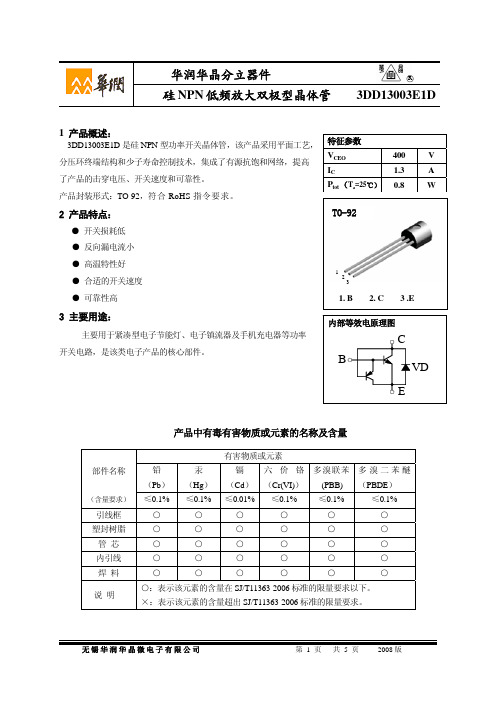
Ta=-55℃
1
0.01
0.1
1
Ic(A)
无锡华润华晶微电子有限公司
第 3 页 共5 页
2008 版
华润华晶分立器件
○R
3DD13003E1D
图 5 VCEsat - IC关系曲线
图 6 VBEsat - IC关系曲线
VCEsat1(V0 ) 1
0.1
0.01 0.01
VBEsa1t(.V3)
Ta=125℃
华润华晶分立器件 硅 NPN 低频放大双极型晶体管
○R
3DD13003E1D
1 产品概述:
3DD13003E1D 是硅 NPN 型功率开关晶体管,该产品采用平面工艺, 特征参数
分压环终端结构和少子寿命控制技术,集成了有源抗饱和网络,提高 VCEO
400
V
了产品的击穿电压、开关速度和可靠性。 产品封装形式:TO-92,符合 RoHS 指令要求。
除非另有规定,Ta= 25℃
参数名称 集电极-基 极电压 集电极-发射极电压 发射极-基 极电压 集电极电流 耗散功率 结温 贮存温度
符号
VCBO VCEO VEBO
IC Ptot Tj Tstg
○R
3DD13003E1D
额定值
600 400 9 1.3 0.8 150 -55~150
单位
V V V A W ℃ ℃
VCE=5V, IC=0.2A
hFE1:VCE=5V, IC=5mA hFE2:VCE=5V, IC=0.2A IC=0.5A, IB=B 0.1A IC=0.5A, IB=B 0.1A
UI9600,IC=0.1A
VCE=10V, IC=0.1A f=1MHz
爱凡诺变频驱动器产品说明说明书
Eaton DG1-32061FN-C21CEaton PowerXL DG1 variable frequency drive, 208-240V input 15 kW 20 Hp CT 3PH 50/60 Hz 61A output IP21/type 1 enclosure FR4 LCD Internal EMC filter and DC choke EtherNet, RS-485, BACnet MS/TP, Modbus TCP and RTU ports 2 exp slotsGeneral specificationsEaton PowerXL DG1 variable frequency driveDG1-32061FN-C21C 78668588610728 in 17 in15 in 80 lb Eaton Selling Policy 25-000 generally applies with some exceptions. Drive products come with a standard 24 months from date of shipment and 36 months with Eaton certified start up all inclusive coverage parts labor and travel.RoHS Compliant C-Tick Compliant CE Marked GoST-R UL 508C UL Listed cUL Listed IEC 61508 EN 62061 EN ISO 13849-1Product NameCatalog NumberUPCProduct Length/Depth Product Height Product Width Product Weight WarrantyCompliances Certifications Catalog NotesEMI, RFI FilterCoated board61/75 AThree-phase in, three-phase out 230 V, 208-240 V(-15%, +10%) IP21Coated boardIP21/type 161 A2 expansion slots4Power XL3 inputs, 3 outputs15 kW20 hp50-60 HzIncluded Dual Rating What exactly does that mean? Starting, stopping and operationReal time clock and use of the timersLoad balancing in multi motor applications Analog I/OsConnecting drives to generator suppliesDG1 in pump and fan applicationsMotor data and V/f curvesElectromagnetic compatibility (EMC)Smoke Mode and fire modeTorque controlDigital I/OsPID controllerOperating at low temperaturesEaton's Volume 6—Solid-State Motor Control Product Range Catalog Drives Engineering DatasheetDG1_FN_(FR4-UL) 3D InventorDG1_FN_(FR4-UL) AutoCAD 2D Footprint (mm) DG1_FN_(FR4-UL) 2D PDFDG1_FN_(FR4-UL) AutoCAD 2D FootprintDG1_FN_(FR4-UL) 2D Drawing XchangeDG1_FN_(FR4-UL) 3D Model XchangePowerXL DG1 Series VFD Installation Manual PowerXL DG1 Series VFD Application ManualEaton Specification Sheet - DG1-32061FN-C21CProtection filtering Special features Maximum Current PhaseInput voltage RatingMaterialEnclosureOutput current - max Number of slots Frame sizeTypeInput outputPower consumption Horsepower Frequency rating Keypad Application notesCatalogsDrawingsInstallation instructions Specifications and datasheetsEaton Corporation plc Eaton House30 Pembroke Road Dublin 4, Ireland © 2023 Eaton. All Rights Reserved. Eaton is a registered trademark.All other trademarks areproperty of their respectiveowners./socialmediaActive energy control, quick start wizard CT Internal EMC filter, DC choke LCD graphical EtherNet, RS-485, BACnet MS/TP, Modbus TCP and RTU communicationSoftwareTorque rating ProtectionDisplay Communication。
明华RD-EB IC卡读写器
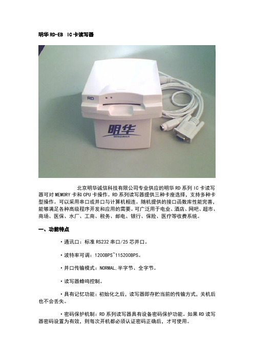
明华RD-EB IC卡读写器
北京明华诚信科技有限公司专业供应的明华RD系列IC卡读写器可对MEMORY卡和CPU卡操作。
RD系列读写器提供三种卡座选择,支持多种卡型操作。
可以采用串口或并口与计算机相连。
随机提供的接口函数库性能完善,能够满足各种高级程序开发和应用的需要。
可广泛用于电业、酒店、网吧、超市、商场、医保、水厂、工商、税务、邮电、银行、保险、医疗等收费系统。
一、功能特点
·通讯口:标准RS232串口/25芯并口。
·波特率可调:1200BPS~115200BPS。
·并口传输模式:NORMAL,半字节、全字节。
·读写器蜂鸣控制。
·具有记忆功能:初始化之后,读写器即存贮当前的传输方式,关机后也不会丢失。
·密码保护机制:RD系列读写器具有设备密码保护功能。
如果RD读写器密码设置为有效,则每次开机都必须认证密码正确后,才可使用。
·接口函数:支持DOS/Windows/NT/UNIX/LINUX环境下的多种编程语言。
随机提供使用范例:方便用户开发应用程序。
·卡座类型:插拔式。
二、技术规格
·温度:0℃-50℃
·相对湿度:30﹪—95﹪
·电源:AC220V±10﹪
·最大功率:100MW
·外型尺寸:150mm(长)×118mm(宽)×100mm(高)
·重量:约500克。
eb挂板参数

eb挂板参数EB挂板是一种比较流行的开发板,通过EB挂板,用户可以轻松实现各种功能扩展,如机器视觉、控制系统、数据采集等。
EB挂板具有较高的扩展性,具体的参数包括以下几个方面:一、处理器性能:EB挂板主要依赖于处理器进行计算和控制。
目前市场上的EB挂板主要使用的处理器是ARM Cortex系列、X86系列以及FPGA。
其中,ARM Cortex系列处理器普遍应用于入门级和中低端的EB挂板,如树莓派、NanoPi等。
X86系列处理器则主要应用于高性能的EB挂板,比如Intel NUC、LattePanda Alpha等。
FPGA则主要应用于需要高度自定义硬件的特定场景。
二、扩展接口:不同的EB挂板拥有不同的扩展接口。
其中,最常用的接口有GPIO、SPI、I2C、UART、USB、CAN等。
GPIO为数字通用输入输出接口,也就是普通的IO口,可以用来控制LED灯等。
SPI和I2C是串行通讯接口,可以与各种传感器和存储接口进行通讯。
UART接口可以和串口设备通讯,如GPS、蓝牙模块等。
USB接口不仅可以连接外部设备,也可以作为主设备连接U盘等外部存储设备。
CAN接口则是连接CAN总线器件。
三、内存和存储:EB挂板需要足够的内存和存储空间来运行各种应用程序。
目前市场上常见的EB挂板内存容量从256MB到8GB不等,主要取决于用户的实际需求。
而存储空间则通常为4GB到128GB不等,也可以采用SD卡或USB接口连接外部存储设备。
四、操作系统和系统架构:EB挂板支持多种操作系统和系统架构,包括Linux、Windows、Android等。
其中,Linux是最常用的操作系统,因为它具有较高的自由度和开放性,并且可以根据用户需求进行自定义开发。
总之,通过了解EB挂板的参数,用户可以更好地选择合适的EB挂板,并且判断EB挂板在各个方面是否与其实际需求相符合,从而更好地实现自己的应用需求。
RTBN 铁路瞬态屏蔽器,130 VDC,110 VAC,产品号 RTB130N说明书
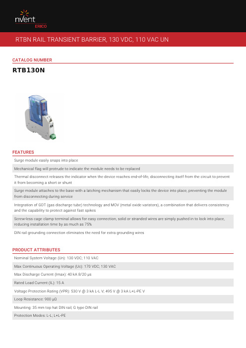
CATALOG NUMBERRTB130NFEATURESSurge module easily snaps into placeMechanical flag will protrude to indicate the module needs to be replacedThermal disconnect releases the indicator when the device reaches end-of-life, disconnecting itself from the circuit to prevent it from becoming a short or shuntSurge module attaches to the base with a latching mechanism that easily locks the device into place, preventing the module from disconnecting during serviceIntegration of GDT (gas discharge tube) technology and MOV (metal oxide varistors), a combination that delivers consistency and the capability to protect against fast spikesScrew-less cage clamp terminal allows for easy connection, solid or stranded wires are simply pushed in to lock into place, reducing installation time by as much as 75%DIN rail grounding connection eliminates the need for extra grounding wiresPRODUCT ATTRIBUTESNominal System Voltage (Un): 130 VDC; 110 VACMax Continuous Operating Voltage (Uc): 170 VDC; 130 VACMax Discharge Current (Imax): 40 kA 8/20 μsRated Load Current (IL): 15 AVoltage Protection Rating (VPR): 530 V @ 3 kA L-L V; 495 V @ 3 kA L+L-PE VLoop Resistance: 900 µΩMounting: 35 mm top hat DIN rail; G type DIN railProtection Modes: L-L; L+L-PEStatus Indication: Mechanical flag; Remote ContactsConnection, Solid: 18 minConnection, Stranded: 18 minEnclosure Material: UL® 94V-0 ThermoplasticEnclosure Rating: IP 20Temperature: −40 to 185 °FDepth: 4.22"Height: 4.33"Width: 0.71"Unit Weight: 0.22 lbComplies With: AREMA® C&S Manual Parts 11.5.1, 11.3.2, 14.1.2; ANSI®/IEEE® C62.41.2-2002 Cat A, Cat B, Cat CColor: YellowReplacement Module: RTBN130MDIAGRAMSWARNINGnVent products shall be installed and used only as indicated in nVent's product instruction sheets and training materials. Instruction sheets are available at and from your nVent customer service representative. Improper installation, misuse, misapplication or other failure to completely follow nVent's instructions and warnings may cause product malfunction, property damage, serious bodily injury and death and/or void your warranty.North America+1.800.753.9221Option 1 – Customer Care Option 2 – Technical Support EuropeNetherlands:+31 800-0200135France:+33 800 901 793EuropeGermany:800 1890272Other Countries:+31 13 5835404APACShanghai:+ 86 21 2412 1618/19Sydney:+61 2 9751 8500 。
BWD3K130干式变压器温控器说明书之欧阳结创编

干式变压器温控器说明书(BWD3K130系列)江西华达电子电脑有限公司安全指导在安装、操作和运行本温控器前,请仔细阅读本说明书,并妥善保管。
本温控器有危险电压,并监控危险的电力变压器。
如果不按本手册的规定操作可能会导致财产损失或人员严重受伤甚至死亡。
只有合格的技术人员才允许操作本温控器,在进行操作前,要熟悉使用手册中所有安全说明、安装、操作和维护规程。
本温控器的正常运行取决于正确的运输、安装、操作和维护。
1. 本温控器的输入电源为:220VAC,50Hz;2. 请确保所有电气连接正确、牢固;3. 本温控器接通电源后,请不要接触外露的带电部件;4. 以下部件带有危险电压:–电源端子2、3;–风机输出端子12、14千万不能短路;5. 对变压器进行高压测试时,请先将温控器与变压器分离,以免损坏温控器!一、产品概述本仪器是我公司为新式风冷干式变压器而设计的新一代电脑温度控制器,它采用美国生产的单片计算机为控制核心,结合最先进的数据存贮技术设计而成,从而使整个产品的性能迈上了一个新台阶。
和传统的模拟与数字电路组成的温度控制器相比,本仪器因采用高性能的微电脑控制器,使所需电子元器件的数量减少一半以上,从而使本仪器的电路设计和结构设计大大简化,这样就极大提高了本仪器的运行可靠性。
我公司生产的电脑温度控制器,温度设定只需通过面板上的几个按键的设置就可实现,而且设定的参数在停电后永不丢失。
本仪器还具有“黑匣子”功能,可记录变压器掉电时刻的线包绕组的温度。
在抗干扰方面,本仪器在设计上采用硬件和软件相结合的抗干扰措施,共同监视温控器的工作,从而达到了极强的抗干扰能力。
在使用方面,本仪器还具有操作简单、安装方便、维护容易的特点。
本产品性能符合JB/T7631-2005《变压器用电子温控器》标准本产品生产体系通过ISO9001:2000质量体系认证本产品被国家科委和国家经贸委评审为1997年度国家重点新产品二、产品型号三、技术参数1 测温范围: -30℃-200℃2 测温精度: 0.5%FS±1个字3 分辨率: 0.1℃4 工作电压: AC176V~AC242V( 50Hz )5 功耗:5VA6 继电器触点容量:10A/220VAC7 仪表重量:<1Kg8 仪表外形尺寸: 160mm×80mm×134mm(宽×高×深)9 开孔尺寸: 152mm×76mm(宽×高)四、产品功能介绍1具有三相线包温度的巡回显示和最高相温度显示的切换功能。
DWA-130中文数据表

易于安装
D-Link快速网卡安装向导能协助您完成安装流程,并配置新的无线 N USB网卡。同时附带的无线连接管理器可以添加并保存您常用的网络设置。
使用方便
无线 N USB网卡可以很容易地将拥有USB 2.0接口的台式计算机或笔记本电脑连接到网络中,从而接入Internet和共享文件。台式计算机用户可以在 不打开机箱的情况下方便地添加无线连接。通过计算机附带的插口,无线 N USB网卡可以接上您的台式计算机并获得优化的性能。笔记本电脑用户 在保持紧凑体积的同时,也可以升级到无线N技术,并获得更好的性能。 将台式计算机或笔记本电脑上现有的802.11g无线网卡升级至新的无线N USB网卡(DWA-130),享受由新的技术带来的无线速率的增长以及覆盖范围 的增加。
技术规格
标准 + IEEE 802.11n (草案2.0) + IEEE 802.11g
运行温度 0˚ ~ 40˚C (32˚ ~ 104˚F)
接口 + USB 2.0 2
运行湿度 10 ~ 90% (无凝结)
频段 + 2.4GHz~2.4835GHz
尺寸 + (宽x长x高) 27.94 x 86.36 x 12.7 毫米 (1.1 x 3.4 x 0.5 英寸)
130dwa130技术规格标准运行温度ieee80211n草案20ieee80211g接口0?40?c32?104?f运行湿度产品特性可将您的台式计算机或笔记本电脑接入无线网络并且在室内任何位置都可以高速访问internet连接传输文件及流媒体
无线 N USB网卡
将台式计算机或笔记本电脑 接入无线网络中
ACN 052 202 83 8
变频强热D系列产品介绍

膨胀 水箱
容积 最高水压 预压
配管连接直径
配管
安全阀
mm kPa W L L/min L Mpa MPa inch inch Mpa
5HP
6HP
RWMG-160FEWN1Q
单相 50Hz 220V
751×562×320
水冷式
3
23
264
壳管换热器
2.875
45.9
8
0.3
0.1
1-1/4"
1-1/4"
2 排气阀 8 入水口
3 安全阀 9 水流开 关
4 换热器 10 水泵
5 液管接 11 压力开
口
关
6 气管接 12 水过滤
口
器
• 三 室外机简介
• •参数简介 5
匹数 室外机
型号
电源
-
5HP
6HP
-
RAS-140FEWN1Q RAS-160FEWN1Q
-
1Φ 220V50Hz
外形寸法 H×W×D
安装位置必须能够承受机组的运转重量。 远离电磁波、避免阳光直射。远离腐蚀性气体。 水模块运转噪音应不影响用户起居、办公。 安装位置应留有足够的维修空间。
水模块尺寸
安装维修空间
顶部预留60mm的距离。 机组左侧预留400mm以上。 机组前侧预留400mm以上。
• •其它部品说明 5
•1.采用国际品牌排水泵——威乐排水泵;
•2.无辅助电加热。
• 由于此款机型制热性能强,运行范围广,因此,取消 辅助电加热。
• 四 水模块简介
• •参数简介 6
水模块
型号 电源 尺寸
主要部件
水回路
电力用逆变器之欧阳历创编

电力用逆变器用户手册出版说明内容介绍为指导相关电源设备生产厂、设计院利用我公司的相关产品设计生产电源系统,特编制本技术指导书。
本书详细地描述了2~10KVA系列单机版逆变器的外观、功能和参数指标、接口定义和操作说明等内容。
读者对象本书适合于电源合作生产厂家、用户、设计与维护工程师等。
本书的约定一、产品上标记警告高压在高压存在的地方张贴此标记。
保护性接地端在产品外壳保护接地端上丝印标记。
二、手册中标记注意注意字句指可能造成本设备或其它设备损坏的状况或做法。
目录1 概述 (1)2 工作原理 (1)3 技术特点 (2)4 技术参数 (2)5 外形与接口 (3)5.1 前面板 (3)5.1.1 LED工作指示灯说明 (4)5.1.2 LCD液晶显示说明 (4)5.1.3 操作按键说明 (4)5.2 后面板 (5)6 操作说明 (5)6.1 运行数据 (6)6.2 系统状态 (7)6.3 用户设置 (7)6.4 调试信息 (7)6.5 用户校准 (8)7 机械规格 (9)7.1 外形尺寸 (9)7.2 面板开孔尺寸 (10)8 环境条件 (10)8.1 工作温度 (10)8.2 非工作温度 (10)8.3工作湿度 (10)8.4 运行高度 (10)8.5 噪声 (10)8.6 冷却方式 (11)1 概 述FBIV 系列电力用高频逆变器秉承模块化设计理念,采用DSP 数字控制技术、高频软开关技术,效率高、可靠性高;逆变器直流输入与交流输出完全电气隔离,满足电力行业相关要求;逆变器内置CPU ,自带独立LCD 显示。
功率接线采用栅型端子,对应产品型号如下:备注:1、此说明书是按照2-5K 逆变电源编制,1K 、8K 、10K 说明书另见分册。
差异主要在结构、功率回路及功率接口大小,控制原理一样可做参考。
2、1KVA 逆变器模块采用9.5英寸1U 标准机箱;2KVA 逆变器模块采用2U 标准机箱;8-10KVA 逆变器模块采用3U 标准机箱。
高频变压器大全之欧阳术创编
EF型高频变压器详细资料•EF型高频变压器•各种电子、电器线路的必需元件之一•做工优良,品质保证ET型高频变压器详细资料具有杂散电容小,纹波系数低,电感偏差小等特点用于彩色电视电源,液晶显示电源,电脑开关电源,电子镇流器等主要型号有:DL-ET24、DL-ET28、DL-ET28A等EFD型高频变压器详细资料EFD型变压器是为了适应超薄型开关电源而设计的一款高频变压器。
它拥有扁型的铁氧体磁芯,它的形状能同时满足电源变压器高功率的要求和超薄体积的要求,同样也能适应开关电源在温升方面的要求,但对PCB板的要求会提高;其它性能接近于EE型和EC型变压器。
EFD变压器常用型号有EFD15,EFD20,EFD25,EFD30等.ER/EC型高频变压器详细资料EC/ER型变压器是基本型的铁氧体磁芯,它们被广泛用于开关电源及和多种电子线路中,振荡方式有全桥,半桥,单端式,谐振式,推挽式线路等,具有优良的材料特性,适用于典型的变压器结构,EC/ER磁芯的圆柱型中心柱,使之绕线较为容易,并增大了绕组的截面积,可增大输出功率,适用于各种开关电源变压器和阻流线圈。
EC型变压器的型号有EC2820,EC3542,EC4042,EC4950,EC5345,EC70等。
下表列出部分产品的外形尺寸及输出功率。
随着磁材特性和工作频率的不同,最大输出功率会有所不同,表中数据仅供参考。
测试条件1KHz/1V,耐压AC2000V,绝缘电阻:DC500V ≥200MΩ。
序号规格外型尺寸mm 参考VA 重量A B C f=50KHz f=100KHz 参考值g1 EC-28 28 34 30 42 58 352 EC-35 35 46 29 100 150 783 EC-40 40 47 32 180 290 1104 EC-42 42 47 41 240 380 1255 EC-49 49 58 53 650 1000 191以上数据仅供参考。
- 1、下载文档前请自行甄别文档内容的完整性,平台不提供额外的编辑、内容补充、找答案等附加服务。
- 2、"仅部分预览"的文档,不可在线预览部分如存在完整性等问题,可反馈申请退款(可完整预览的文档不适用该条件!)。
- 3、如文档侵犯您的权益,请联系客服反馈,我们会尽快为您处理(人工客服工作时间:9:00-18:30)。
Document No. D10213EJ5V0DS00 (5th edition)Date Published December 1998 N CP(K)Printed in Japan©1981DATA SHEET元器件交易网2ELECTRICAL CHARACTERISTICS (T A = 25 ˚C)Zener Voltage Dynamic Knee Dynamic Reverse CurrentType SuffixV Z (V)Note 1Impedance ImpedanceI R (µA) NumberZ Z (Ω)Note 2 Z ZK (Ω)Note 2MIN.MAX.I Z (mA)MAX.I Z (mA)MAX.I Z (mA)MAX.V R (V)B1.882.20RD2.0EB1 1.88 2.1020140202 00011200.5B2 2.02 2.20B2.12 2.41RD2.2EB1 2.12 2.3020120202 00011200.7B2 2.22 2.41B2.33 2.63RD2.4EB1 2.33 2.5220100202 00011201.0B2 2.43 2.63B2.54 2.91RD2.7EB1 2.54 2.7520100201 00011001.0B2 2.69 2.91B2.853.22RD3.0EB1 2.85 3.072080201 0001501.0B2 3.01 3.22B3.16 3.53RD3.3EB1 3.16 3.382070201 0001201.0B2 3.32 3.53B3.47 3.83RD3.6EB1 3.47 3.682060201 0001101.0B2 3.62 3.83B3.774.14RD3.9EB1 3.77 3.982050201 000151.0B2 3.92 4.14B4.05 4.53RD4.3EB1 4.05 4.262040201 000151.0B2 4.20 4.40B3 4.34 4.53B4.47 4.91RD4.7EB1 4.47 4.65202520900151.0B2 4.59 4.77B3 4.71 4.91B4.855.35RD5.1EB1 4.85 5.03202020800151.5B2 4.97 5.18B3 5.12 5.35B5.29 5.88RD5.6EB1 5.29 5.52201320500152.5B2 5.46 5.70B3 5.64 5.88B5.816.40RD6.2EB1 5.81 6.06201020300153.0B2 5.99 6.24B3 6.16 6.40B6.32 6.97RD6.8EB1 6.32 6.59208201500.523.5B2 6.52 6.79B36.706.97Zener Voltage Dynamic Knee DynamicReverse CurrentTypeSuffix V Z (V)Note 1Impedance ImpedanceI R (µA)Number Z Z (Ω)Note 2 Z ZK (Ω)Note 2MIN.MAX.I Z (mA)MAX.I Z (mA)MAX.I Z (mA)MAX.V R(V)B 6.887.64RD7.5E B1 6.887.19208201200.50.5 4.0 B27.117.41B37.337.64B7.568.41RD8.2E B17.567.90208201200.50.5 5.0 B27.828.15B38.078.41B8.339.29RD9.1E B18.338.70208201200.50.5 6.0 B28.618.99B38.899.29B9.1910.30RD10E B19.199.59208201200.50.27.0 B29.489.90B39.8210.30B10.1811.26RD11E B110.1810.631010101200.50.28.0 B210.5010.95B310.8211.16B11.1312.30RD12E B111.1311.631012101100.50.29.0 B211.5011.92B311.8012.30B12.1813.62RD13E B112.1812.711014101100.50.210 B212.5913.16B313.0313.62B13.4815.02RD15E B113.4814.091016101100.50.211 B213.9514.56B314.4215.02B14.8716.50RD16E B114.8715.501018101500.50.212 B215.3315.96B315.7916.50B16.3418.30RD18E B116.3417.061023101500.50.213 B216.9017.67B317.5118.30B18.1120.72B118.1118.92RD20E B218.7319.571028102000.50.215 B319.3820.22B419.8820.72B20.2322.61B120.2321.08RD22E B220.7621.6553052000.50.217 B321.2222.09B421.6822.6134Zener VoltageDynamic Knee DynamicReverse Current TypeSuffix V Z (V)Note 1Impedance ImpedanceI R (µA)Number Z Z (Ω)Note 2 Z ZK (Ω)Note 2MIN.MAX.I Z (mA)MAX.I Z (mA)MAX.I Z (mA)MAX.V R(V) B22.2624.81B122.2623.12RD24E B223.7523.7353552000.50.219 B323.2924.27B423.8124.81B24.2627.64B124.2625.52RD27E B224.9726.2654552500.50.221 B325.6326.95B426.2927.64B26.9930.51B126.9928.39RD30E B227.7029.1355552500.50.223 B328.3629.82B429.0230.51B29.6833.11B129.6831.22RD33E B230.3231.8856552500.50.225 B330.9032.50B431.4933.11B32.1435.77B132.1433.79RD36E B232.7934.4957552500.50.227 B333.4035.13B434.0135.77B34.6840.80B134.6836.47B235.3637.19RD39EB336.0037.8558552500.50.230 B436.6338.52B537.3639.29B638.1440.11B738.9440.80RD43E B404559050.233 RD47E B444959050.236 RD51E B4854511050.239 RD56E B5360511050.243 RD62E B5866220020.247 RD68E B6472220020.252 RD75E B7079230020.257 RD82E B7787230020.263 RD91E B8596240020.269 RD100E B94106240020.276 RD110E B104116175010.284 RD120E B114126190010.291 RD130E B1201401110010.2100 RD140E B1301501130010.2110 RD150E B1401601150010.2120 RD160E B1501701170010.2130 RD170E B1601801190010.2140 RD180E B1701901220010.2140 RD190E B1802001240010.2150 RD200E B1902101250010.2160 Note 1.tested with pulse (40 ms)2.Z Z and Z ZK are measured at I Z by given a very small A.C. current signal.3.Suffix B is Suffix B1, B2, B3, B4, B5, B6 or B7.5TYPICAL CHARACTERISTICS (T A = 25 ˚C)100101V z – Zener Voltage – VI z – Z e n e r C u r r e n t – AFig. 1 ZENER CURRENT vs. ZENER VOLTAGE100 m10 m1 mµ100µ10µ1100 n10 n1 nI z – Z e n e r C u r r e n t – AFig. 2 ZENER CURRENT vs. ZENER VOLTAGEV z – Zener Voltage – V100 m10 m1 mµ100µ10µ1100 n10 n1 nI z – Z e n e r C u r r e n t – AFig. 3 ZENER CURRENT vs. ZENER VOLTAGEV z – Zener Voltage – V100 m10 m1 mµ100µ10µ1100 n10 n1 nI z – Z e n e r C u r r e n t – AFig. 4 ZENER CURRENT vs. ZENER VOLTAGEV z – Zener Voltage – V6100 m10 m1 mµµ10µ1100 n10 n1 nV z – Zener Voltage – VIz–ZenerCurrent–AFig. 5 ZENER CURRENT vs.ZENER VOLTAGE100100 m10 m1 mµµ10µ1100 n10 n1 nV z – Zener Voltage – VIz–ZenerCurrent–AFig. 7 ZENER CURRENT vs.ZENER VOLTAGE100100 m10 m1 mµµ10µ1100 n10 n1 nIz–ZenerCurrent–AFig. 6 ZENER CURRENT vs.ZENER VOLTAGE100V z – Zener Voltage – V7Fig. 8 POWER DISSIPATION vs. AMBIENT TEMPERATURE020406080100120140160180200100200300400500600T A – Ambient Temperature – ˚CP – P o w e r D i s s i p a ti o n – m VFig. 9 POWER DISSIPATION vs. AMBIENT TEMPERATURE020406080100120140160180200100200300400500600T A – Ambient Temperature – ˚CP – P o w e r D i s s i p a t i o n – m VFig. 10 THERMAL RESISTANCE vs. SIZE OF P.C BOARD020*********100200300400500600S – Size of P.C Board – mm 2R t h – T h e r m a l R e s i s t a n c e – ˚C /WFig. 11 THERMAL RESISTANCE vs. SIZE OF P.C BOARDS – Size of P.C Board – mm 2I Z – Zener Current – mA 1101001 000Z Z – D y n a m i c I m p e d a n c e – ΩZ Z – D y n a m i c I m p e d a n c e – Ω10 0001 00010010I Z – Zener Current – mAFig. 12 DYNAMIC IMPEDANCE vs. ZENER CURRENTFig. 13 DYNAMIC IMPEDANCE vs. ZENER CURRENT80.10γ Z – Z e n e r V o l t a g e T e m p e r a t u r e C o e f f i c i e n t – %/˚C/˚CFig. 14ZENER VOLTAGE TEMPERATURECOEFFICIENT vs. ZENER VOLTAGE V Z – Zener Voltage – Vγ Z – Z e n e r V o l t a g e T e m p e r a t u r e C o e f f i c i e n t – %/˚Cγ’Z –/˚Cγ’Z – Z e n e r V o l t a g e T e m p e r a t u r e C o e f f i c i e n t – m /˚CFig. 15ZENER VOLTAGE TEMPERATURECOEFFICIENT vs. ZENER VOLTAGE9GENERAL PURPOSE INFORMATION•Power DissipationTotal power dissipation P can be calculated by the maximum junction temperature, ambient temperature and thermal resistance.P =T jMAX. – T A T jMAX.:Maximum Junction Temperature R thT A :Ambient TemperatureR th:Thermal Resistance (to see Fig. 10, 11)1 0001001011µ10µ100µ 1 m 10 m 100 mt T – Pulse Width – sP A S M – S u r g e R e v e r s e P o w e r – WFig. 17 SURGE REVERSE POWER RATINGS[MEMO] 10[MEMO]11No part of this document may be copied or reproduced in any form or by any means without the prior written consent of NEC Corporation. NEC Corporation assumes no responsibility for any errors which may appear in this document.NEC Corporation does not assume any liability for infringement of patents, copyrights or other intellectual property rights of third parties by or arising from use of a device described herein or any other liability arising from useof such device. No license, either express, implied or otherwise, is granted under any patents, copyrights or other intellectual property rights of NEC Corporation or others.While NEC Corporation has been making continuous effort to enhance the reliability of its semiconductor devices, the possibility of defects cannot be eliminated entirely. To minimize risks of damage or injury to persons or property arising from a defect in an NEC semiconductor device, customers must incorporate sufficient safety measures in its design, such as redundancy, fire-containment, and anti-failure features.NEC devices are classified into the following three quality grades:"Standard", "Special", and "Specific". The Specific quality grade applies only to devices developed based on a customer designated "quality assurance program" for a specific application. The recommended applications ofa device depend on its quality grade, as indicated below. Customers must check the quality grade of each device before using it in a particular application.Standard:Computers, office equipment, communications equipment, test and measurement equipment, audio and visual equipment, home electronic appliances, machine tools, personal electronicequipment and industrial robotsSpecial:Transportation equipment (automobiles, trains, ships, etc.), traffic control systems, anti-disaster systems, anti-crime systems, safety equipment and medical equipment (not specifically designedfor life support)Specific:Aircrafts, aerospace equipment, submersible repeaters, nuclear reactor control systems, life support systems or medical equipment for life support, etc.The quality grade of NEC devices is "Standard" unless otherwise specified in NEC's Data Sheets or Data Books.If customers intend to use NEC devices for applications other than those specified for Standard quality grade, they should contact an NEC sales representative in advance.Anti-radioactive design is not implemented in this product.M4 96.5 12。
