An Internal Second Parameter Problem in the Sculptor Dwarf Spheroidal Galaxy
机器学习题库

机器学习题库一、 极大似然1、 ML estimation of exponential model (10)A Gaussian distribution is often used to model data on the real line, but is sometimesinappropriate when the data are often close to zero but constrained to be nonnegative. In such cases one can fit an exponential distribution, whose probability density function is given by()1xb p x e b-=Given N observations x i drawn from such a distribution:(a) Write down the likelihood as a function of the scale parameter b.(b) Write down the derivative of the log likelihood.(c) Give a simple expression for the ML estimate for b.2、换成Poisson 分布:()|,0,1,2,...!x e p x y x θθθ-==()()()()()1111log |log log !log log !N Ni i i i N N i i i i l p x x x x N x θθθθθθ======--⎡⎤=--⎢⎥⎣⎦∑∑∑∑3、二、 贝叶斯假设在考试的多项选择中,考生知道正确答案的概率为p ,猜测答案的概率为1-p ,并且假设考生知道正确答案答对题的概率为1,猜中正确答案的概率为1,其中m 为多选项的数目。
CS1611Dimmable LED Design Guide AN364中文版翻译要点
3.2设计步骤概述CS1610/11 LED驱动IC控制电源转换系统,有两个不同的电源转换阶段。
IC 需要配套的电路,以栅偏压,箝压电路和EMI滤波,来提供一个稳定的状态电源电路。
建议的设计过程概述如下:1。
回扫阶段的开始。
2。
在全功率的最小电源V(BST)的设计时应注意,任何设计都可能需要取舍不同的运行参数。
3。
通过验证和设计重复来优化回扫阶段。
4。
以功率回扫阶段的要求,来决定升压阶段设计。
5。
无调光模式,启动升压阶段设计。
6。
确定在升压电感器的峰值电流,Ipk(BST)7。
确定一个升压电感L(BST),在定义的范围内,调整开关频率。
要考虑到对EMI的影响。
8。
在峰值电流额定值下挑选升压FET。
9。
选择电源组件。
10.完成非电源转换电路:ZCD,OVP,eOTP,箝压电路,电荷泵和偏置电路。
11.设计EMI滤波器。
12.为PCB布线。
在全亮度(满载)点进行反激阶段设计。
为了达到最佳的解决方案,设计的过程可能需要反复几次。
尤其是EMI滤波器,是至关重要的,因为只有很小的自由度来选择能满足以下要求的EMI元件:•符合EMI规范•实现最大的品种,调光器的兼容性•柔和调光,一个调光器来控制一些可变数量的灯具时无频闪3.3反激式阶段设计图2说明了设计的反激式阶段的步骤。
图略反激式设计的步骤1。
设置升压输出电压,V(BST)2。
选择MOSFET要质量标准一致的设计公司。
3。
通过V(BST),FET 电压,反射电压和V来确定变压器匝数比。
4。
在T3时间,使用额定的开关频率和一个初始评估来确定在全亮度下的时间TT值5。
用V(BST), TT,和V来确定时间T1和T2。
6。
用时间T2和TT,匝比n和负载电流来确定峰值初级电流值,I。
7。
用I来确定R( )。
8。
用时间T1计算原边电感。
9。
满负荷条件下计算反激式增益电阻R( )。
确保与昏暗相对的负载线性曲线。
10。
用I和占空比来计算初级和次级RMS电流11。
选择一个输出电容。
E5CSL E5CWL温度控制器使用说明书

E5CSL/E5CWL T emperature Controller Instruction Manual Thank you for purchasing the OMRON E5CSL/E5CWL Temperature Controller. This manual describes the functions, performance, and application methods needed for optimum use of the product.Please observe the following items when using the product.• This product is designed for use by qualified personnel with a knowledge of electrical systems.• Before using the product, thoroughly read and understand this manual to ensure correct use.• Keep this manual in a safe location so that it is available for reference whenever required.©All Rights Reserved Suitability for Use OMRON shall not be responsible for conformity with any standards, codes, or regulations that apply to the combination of the products in the customer's application or use of the product. Take all necessary steps to determine the suitability of the product for the systems, machines, and equipment with which it will be used.Know and observe all prohibitions of use applicable to this product.NEVER USE THE PRODUCTS FOR AN APPLICATION INVOLVING SERIOUS RISK TO LIFE OR PROPERTY WITHOUT ENSURING THAT THE SYSTEM AS A WHOLE HAS BEEN DESIGNED TO ADDRESS THE RISKS, AND THAT THE OMRON PRODUCT IS PROPERLY RATED AND INSTALLED FOR THE INTENDED USE WITHIN THE OVERALL EQUIPMENT OR SYSTEM.See also product catalog for Warranty and Limitation of Liability.CAUTION Do not touch the terminals while power is being supplied. Doing so may occasionally result in minor injury due to electric shock.Do not allow pieces of metal, wire clippings, or fine metallic shavings or filings from installation to enter the product. Doing so may occasionally result in electric shock, fire, or malfunction.Do not use the product where subject to flammable or explosive gas. Otherwise, minor injury from explosion mayoccasionally occur.Never disassemble, modify, or repair the product or touch any of the internal parts. Minor electric shock, fire, or malfunction may occasionally occur. If the output relays are used past their life expectancy, contact fusing or burning may occasionally occur. Always consider the application conditions and use the output relays within their rated load and electrical life expectancy. The life expectancy of output relays varies considerably with the output load and switching conditions.Tighten the terminal screws to between 0.74 and 0.90 N·m. Loose screws may occasionally result in fire.Set the parameters of the product so that they are suitable for the system being controlled. If they are not suitable, unexpected operation may occasionally result in property damage or accidents.EN Models with Single Display Models with Dual Display E5CSL- R Relay output: 250 VAC, 3 A Q Voltage output (for driving SSR): 12 VDC, 21 mA Control output 131Sensor type 31 Relay output: 250 VAC, 1 A (resistive load)Alarm (E5CWL only)2E5CWL- 1123• Insert the Controller through the hole in the panel. Push the adapter on from therear to secure the Controller.• Make sure that the surrounding temperature does not exceed the allowable operating temperature given in the specifications, especially when two or more Controllers are mounted.• The voltage output (control output) is not electrically isolated from the internalwiring. One or the other of the control output terminals must therefore be leftungrounded when using a grounded thermocouple thermometer. (If both are grounded, measurements will be unreliable due to sneak current.)Individual Mounting Side-by-side Mounting TC Thermocouple (K, J, T, R, or S)P Platinum resistance thermometer (Pt100)The standby sequence is cleared when the alarm OFF condition has been met.The standby sequence is started again when any of the following conditions is met.• Operation is started (power is turned ON or operation is switched from stop to run).• The alarm value is changed.• The temperature input offset is changed.• The set point is changed.Standby sequence clearedAlarm value Alarm with standby sequenceProcess value TimeAlarm without standby sequence Example: Deviation Lower Limit Standby Sequence ONThe default alarm type is 2.• The control output and the alarm output will turn OFF when an error occurs.(For s.err , the alarm output will be processed for a high temperature error.)• If the input value exceeds the display limit (-1999 to 9999) but it is still within the control range, [[[[ will be displayed for values under -1999.Under these conditions, the control output and alarm output will operate normally.*1: This error is displayed only when the process value and set point are displayed.*2: If the display does not change, the Controller needs to be repaired.If operation returns to normal, then noise may have caused the problem. Check for noise.*3: On the E5CSL, e111 and sum will alternate on the display at 1-second intervals.On the E5CWL, e111 will be displayed on display No. 1 and sum will be displayed on display No. 2. * * * * *The default input type is 8.The default input type is 0.−300 to 23000.0 to 900.0−100 to 15000.0 to 750.0−300 to 700−199.9 to 700.00 to 30000 to 3000−200 to 1300−20.0 to 500.0−100 to 850−20.0 to 400.0−200 to 400−199.9 to 400.00 to 17000 to 1700Input Setting range (°C)Setting range (°F)t -n i l.adj t p a o Input Typeinpt at AT Execute/Cancel d-u Temperature Unit s n i t p k o TemperatureInput Shift cntl PID • ON/OFF al-1Alarm Value*E5CWL only p Proportional Band cp Control Period r-s RUN/STOP i Integral Time oreV Direct/ReverseOperation d Derivative Time alt1Alarm Type *E5CWL only of-r hys HysteresisOperation/Adjustment Protect Initial Setting Protect Operation Control Key Protect PV/SP Set Point *E5CSL only Manual Reset Value Adjustment Level 100SP 25SP for less for at least 3 seconds.Protect Level Operation Level +Adjustment Level POWER ON Initial Setting Level 100 to 240 VAC, 50/60 Hz85% to 110% of the rated voltageApprox. 3.5 VARelay output: 250 VAC, 3 A (resistive load)Voltage output (for driving SSR): 12 VDC+25%/−15%, 21 mA Relay output: 250 VAC, 1 A (resistive load)ON/OFF or 2-PID control 100,000 operations 250 ms −10 to 55°C (with no freezing or condensation)Thermocouple: K, J, T, R, or S (JIS C 1602-1995 and IEC 60584-1)Platinum resistance thermometer: Pt100(JIS C 1604-1997 and IEC 60751)Control output Recommended fuse Weight Degree of protection Alarm output Control method Electrical life of relay Sampling period Malfunction vibration Vibration resistance Ambient temperature Ambient humidity Storage temperature Altitude Installation environment Memory protection Indication accuracy (ambient temperature: 23°C)25% to 85%Power supply voltage Operating voltage range Power consumption −25 to 65°C (with no freezing or condensation)2,000 m max.T2A, 250 VAC, time-lag, low-breaking capacity Approx. 100 g (Controller only)Front panel: IP50, Rear case: IP20,Terminal section: IP00Installation category II,pollution degree 2 (as per IEC 61010-1)Non-volatile memory(number of write operations: 100,000)Sensor type Alarm type No alarm Deviation upper/lower limit Deviation upper limit Deviation lower limit Deviation upper/lower range D eviation upper/lower limit standby sequence ON Deviation upper limit standby sequence ON Deviation lower limit standby sequence ON Absolute value upper limit Absolute value lower limit Absolute value upper limit standby sequence ON Absolute value lower limit standby sequence ON Do not set.Output OFF Positive alarm value (X)Negative alarm value (X)Always ON Always OFF Always OFF Process value LevelSetting Adjustment LevelOperationLevel PV/SPOthers (Alarm Value): Operation control keys are enabled but operation control using parameters is disabled.: Operation control keys are disabled but operation control usingparameters is enabled.: Operation control keys and operation control using parametersare disabled.Default: 0Operation ControlAT Execute/Cancel (M +D )RUN/STOP (M +U )01234SettingLevel 10Do not set.2SettingInitial Setting Level Default: 1• Operation/Adjustment Protection • Initial Setting Protection • Operation Control Key Protection+−AB B Pt inputAlarm Output• Relay output: 250 VAC, 1 A(resistive load)Input power supply:100 to 240 VAC,50/60 HzDO NOT USE Control output +−TC inputM M MM M M M MM M M M M M MM M Step 3Adjustment Level: Used to tune parameters and set control parameters. Adjustment Level AT Execute/Cancel Temperature Input Shift Proportional Band Integral Time Derivative Time Manual Reset Value Hysteresis l.adj at ins p i d of-r hys This display indicates that you have moved to Adjustment Level.Starts and stops autotuning. (Displayed only when PID control is selected.)*1*2Set a compensation value for the temperature input in increments of 0.1°C or 0.1°F.Set the proportional band in increments of 0.1°C or 0.1°F.(Displayed only when PID control is selected.) Set the integral time in increments of 1 s. (Displayed only when PID control is selected.) Set the derivative time in increments of 1 s. (Displayed only when PID control is selected.) Set the manipulated value to use for P or PD control (I = 0). The offset will be canceled. Set the hysteresis to use to achieve stable operation when switching the control output ON/OFF during ON/OFF control. (Displayed only when ON/OFF control is selected.) off /on -199.9 to 999.90.1 to 999.90 to 39990 to 39990.0 to 100.00.1 to 999.9OFF 0.0 (°C)8.0 (°C)233 (s)40 (s)50.0 (%)1.0 (°C)Step 4Protect Level: Used to set parameters to restrict key operations.Operation/Adjustment Protect Initial Setting Protect Operation Control Key Protect oapt inpt okpt Set protection for Operation Level and Adjustment Level.Set protection for Initial Setting Level. Set protection for the AT Key and RUN/STOP Key (operation control keys). *Refer to table on the right.*Refer to table on the right.*Refer to table on the right. 010Step 2Operation Level: Used to monitor the process value and to set the set point, alarm value, etc.PV/SP Alarm value RUN/STOP Monitor the process value and set the set point.Set the alarm value. The location of the decimal point depends on the input type. *E5CWL only.Start and stop control operation. *1-1999 to 9999run /stop SV: 0 (°C)0 (°C)RUN Display Parameter name Description Setting/monitoring range Default Step 1Initial Setting Level: Used to set basic specifications.Input Type Temperature Unit PID • ON/OFF Control Period Direct/Reverse Operation Alarm Type in-t d-u cntl cp ore?alt1Set the input sensor type.Set the unit for temperature input to Celsius (°C) or Fahrenheit (°F).Set either 2-PID control or ON/OFF control.Set the time-proportional control period for the control output. (Displayed only when PID control is selected.) Set either reverse option (heating control) or direct operation (cooling control). Set the alarm type.*E5CWL only.c (°C)/f (°F)onof /pid 0.5, 1 to 990 or 8°C ON/OFF 20 or 2 (s)Or-r (reverse control)2 (Deviation upper limit)or-r (reverse control)or-d (direct control)*1: Displayed only when Operation Control Key Protection is set to 4.*2: The setting cannot be changed during autotuning. Autotuning will be stopped if you move to Initial Setting Level or stop control operation. • Displays during AutotuningE5CSL: The current deviation indicator will flash. E5CWL: The AT Execute/Cancel characters on display No. 1 and the PV/SP characters on display No. 2 will flash.K J T R S Setting 01234567Check the wiring of inputs, disconnections, short circuitsand input type.T urn the power OFF then back ON again.*2Press the U and D Keys for at least 3 seconds to initialize the settings and clear the non-volatile memory error.*2Display Action s.err (S.ERR)e111(E111)e111/sum (E111)/(SUM) *3Meaning Input error *1RAM memory error Non-volatile memory memory error −300 to 1500−199.9 to 900.0−200 to 850−199.9 to 500.0Pt10089Safety Precautions Indicates a potentially hazardous situation which, if not avoided, is likely to result in minor or moderate injury or property damage. Read this manual carefully before using the product.CAUTION Package Contents • Temperature Controller • Adapter • Instruction Manual 460645844.8×44.848×48Adapter • Solderless terminal size: M3.5• Terminal Cover: E53-COV19 (sold separately)• Front Panel: E53-COV20 (sold separately)Recommended panel thickness is 1 to 5 mm.1(10) D Down Key: Reduces the setting.(11) U Up Key: Increases the setting.(12) O +M Press these keys for at least 3 seconds in Operation Level or Adjustment Level to go to Protect Level.Press these keys for at least 1 second in Protect Level to return to Operation Level.(13)M +D Press these keys for at least 2 seconds to start or stop autotuning.*1(14) M +U Press these keys for at least 2 seconds to start or stop operation.*2(3)(7)(4)(9)(8)(12)(13)(14)(11)(12)(13)(14)(11)(10)(2)(1)(10)(6)(6)(7)(8)(5)(1)(9)E5CSL E5CWL D Key or U Key Input Type Parameter Display Parameter SettingDisplay Press the U or D Key at the display for the parameter for which the setting is to be changed. The parameter setting display will appear.Use the U or D Key to change the setting. Example: Changing the Input Type from 0 to 1in-t 0Procedure for Changing E5CSL Settings After 2 seconds U Flashes quickly.Setting confirmed.*1: These keys are disabled when starting and stopping autotuning has been disabled with operation control key protection.*2: These keys are disabled when starting and stopping operation has been disabled with operation control key protection.Control Output• Relay output: 250 VAC, 3 A (resistive load)• Voltage output (for driving SSR): 12 VDC, 21 mAAlarm hysteresis(always 0.2 °C/°F)23457891045+0.60+1.004560 min.+0.6045+0.60(48 x number of Controllers − 2.5)OMRON CORPORA TION Key to Warning Symbols Warning Symbols SpecificationsWiring Model Number Legends Dimensions (mm)Installation (mm)Connections Front Panel Part Names and Functions(1) Display No. 1 Displays the process value (PV) or parameter. For the E5CSL, the set point or parameter setting is also displayed.(2) Display No. 2 Displays the set point (SP) or parameter setting.(3) Deviation Indicators Show the relation between the process value and the set point. Lit: The process value is more than 5°C/°F higher than the set point. Lit: The process value is more than 5°C/°F lower than the set point. Lit: The process value is within 5°C/°F of the set point. The relevant deviation indicator will flash during autotuning.(4) SP Lit while the set point is displayed on display No. 1 (E5CSL only). (5) ALM Lit while the alarm is ON. Not lit while the alarm is OFF. (6) OUT Lit while the control output is ON. Not lit while the control output is OFF.(7) STOPNot lit during operation. Lit while operation is stopped.(8) O Level Key: Changes the setting level.(9) M Mode Key: Changes the parameter within the setting level.Operation MenuParameter Operations Press Press than 1 second.for at least 1 second.Press Parameter Tables Display Parameter name Description Setting/monitoring range Default Display Parameter name Description Setting/monitoring range Default Display Parameter name Description Setting/monitoring range Default *Refer to table on the right.*Refer to table on the right.al-1r-s Input type: Thermocouple Input Setting range (°C)Setting range (°F)Setting Input type: Platinum Resistance Thermometer Troubleshooting Protection : Can be displayed and changed.: Can only be displayed.: Display or changing to another level is not possible.0 1 2 311OMRON EUROPE B.V.Wegalaan 67-69, NL-2132 JD Hoofddorp The NetherlandsPhone 31-2356-81-300 FAX 31-2356-81-388OMRON ELECTRONICS LLCOne Commerce Drive Schaumburg, IL 60173-5302 U.S.APhone 1-847-843-7900 FAX 1-847-843-7787OMRON ASIA PACIFIC PTE. LTD.No. 438A Alexandra Road # 05-05/08 (Lobby 2),Alexandra Technopark, Singapore 119967 Phone 65-6835-3011 FAX 65-6835-2711OMRON Corporation Shiokoji Horikawa, Shimogyo-ku, Kyoto 600-8530 JAPAN Malfunction shock Shock resistance 10 to 55 Hz, 20 m/s 2 for 10 min each in X, Y and Z directions 10 to 55 Hz, 20 m/s 2 for 2 h each in X, Y and Z directions100 m/s 2, 3 times each in X, Y, and Z directions300 m/s 2, 3 times each in X, Y, and Z directionsMd-u Next Parameter Display*The dimensions are the same for the E5CSL.(±0.5% of indication value or ±1°C, whichever is greater)±1 digit max.R, S thermocouple at 200°C or less: ±3°C ±1 digit max.K, T thermocouple at −100°C or less: ±2°C ±1 digit max.Use a deviation alarm to link the alarm to the SP.If the SP is changed, the alarm operating point will also change.Deviation AlarmUse an absolute value alarm when the alarm is not linked to the SP.Absolute Value Alarm0X ON OFF SP X ON OFF SP X ON OFF SP X ON OFF 0X ON OFF 0X ON OFF 0X ON OFF 0X ON OFF ON OFF SP X XSP XON OFF SP XON OFF SP X X ON OFF SP X X ON OFF SP X ON OFF SP X ON OFF 0X ON OFF0XON OFF 0X ON OFF Set this difference.SP Linked Fixed Set the difference(deviation) from the SP.Set the alarm operating point as the temperature (absolute value).Set the temperature (absolute value) at which to output an alarm.0* Alarms with a Standby SequenceSP X ON OFFAlarmsSetting 0 1 2 3 4 5 6 7 8 9 1011 12Alarm operating point Alarm operating point The alarm is blocked until the first safe-state is reached.Unwanted alarm during start-up are prevented.Deviation/ab solute value alarm Deviation alarmDeviationalarm DeviationalarmDeviation alarm Deviation alarm Deviationalarm Deviationalarm Absolute value alarm Absolutevalue alarm Absolute value alarmAbsolute value alarm Be sure to observe the following precautions to prevent operation failure, malfunction, or adverse affects on the performance and functions of the product. Not doing so may occasionally result in unexpected events.(1) The product is designed for indoor use only. Do not use the product outdoors or in any of the following locations. •Places directly subject to heat radiated from heating equipment.•Places subject to splashing liquid or oil atmosphere. •Places subject to direct sunlight. •Places subject to dust or corrosive gas (in particular, sulfide gas and ammonia gas). •Places subject to intense temperature change.•Places subject to icing and condensation. •Places subject to vibration and large shocks.(2) Use/store within the rated temperature and humidity ranges. Provide forced-cooling if required.(3) To allow heat to escape, do not block the area around the product. Do not block the ventilation holes on the product.(4) Be sure to wire properly with correct polarity of terminals.(5) Use specified size (M3.5, width 7.2 mm or less) crimped terminals for wiring. To connect bare wires to the terminal block, use copper braided or solid wires with a rated temperature of over 70°C and a gauge of AWG24 to AWG14 (equal to a cross-sectional area of 0.205 to 2.081 mm 2). (The stripping length is 5 to 6 mm.) Up to two wires of same size and type, or two crimped terminals can be inserted into a single terminal.(6) Do not wire the terminals which are not used.(7) Allow as much space as possible between the controller and devices that generate a powerful high- frequency or surge. Separate the high-voltage or large-current power lines from other lines, and avoid parallel or common wiring with the power lines when you are wiring to the terminals.(8) Use this product within the rated load and power supply.(9) Make sure that the rated voltage is attained within two seconds of turning ON the power using a switch or relay contact. If the voltage is applied gradually, the power may not be reset or output malfunctions may occur.(10) Make sure that the Controller has 30 minutes or more to warm up after turning ON the power before starting actual control operations to ensure the correct temperature display. (11) A switch or circuit breaker should be provided close to this unit. The switch or circuit breaker should be within easy reach of the operator, and must be marked as a disconnecting means for this unit.(12) Do not use paint thinner or similar chemical to clean with. Use standard grade alcohol.(13) Design system (control panel, etc) considering the 2 second of delay that the controller’s output to be set after power ON.(14) The output may turn OFF when shifting to certain levels. Take this into consideration when performing control.(15) The number of non-volatile memory write operations is limited.Precautions for Safe Use A malfunction in the Temperature Controller may occasionally make control operations impossible or prevent alarm outputs, resulting in property damage. To maintain safety in the event of malfunction of the Temperature Controller, take appropriate safety measures, such as installing a monitoring device on a separate line.Default: 0: Can be displayed and changed.: Display or changing to another level is not possible.2113603-9A CL1for at least 3 seconds.Press for at least 1 second.+Press。
LTC1232 精密电源监控模块说明书

123sn1232 1232fasSYMBOL PARAMETER CONDITIONSMINTYP MAX UNITSV CC Supply Voltage● 4.555.5V V IH ST and PB RST Input High Level ●2V CC +0.3V V ILST and PB RST Input Low Level●–0.30.8VDC ELECTRICAL CHARACTERISTICSSYMBOL PARAMETER CONDITIONS MINTYP MAX UNITS I IL Input Leakage (Note 3)●–11µA I OH Output Current at 2.4V (Note 5)●–1–13mA I OL Output Current at 0.4V (Note 5)●26mAI CC Supply Current (Note 4)●0.52mA V CCTP V CC Trip Point TOL = GND ● 4.5 4.62 4.74 V V CCTP V CC Trip PointTOL = V CC●4.254.37 4.49 V V HYS V CC Trip Point Hysteresis 40mV V RSTRST Output Voltage at V CC = 1VI SINK = 10µA4200mVThe ● denotes the specifications which applyover the full operating temperature. V CC = full operating range.The ● denotes the specifications which apply over the full operatingtemperature. V CC = full operating range.SYMBOL PARAMETER CONDITIONSMIN TYP MAX UNITS t PB PB RST = V IL ●40ms t RST RESET Active Time ●2506101000ms t ST ST Pulse Width●20ns t RPD V CC Detect to RST and RST ●100ns t f V CC Slew Rate 4.75V–4.25V ●300µs t RPU V CC Detect to RST and RSTt R = 5µs●2506101000ms (Reset Active Time)t R V CC Slew Rate 4.25V–4.75V ●0nst TDST Pin Detect to RST and RST TD = GND ●60150250ms (Watchdog Time-Out Period)TD = Floating ●2506101000ms TD = V CC●50012002000ms C IN Input Capacitance 5pF C OUTOutput Capacitance5pFNote 1: Absolute Maximum Ratings are those values beyond which the life of a device may be impaired.Note 2: All voltage values are with respect to GND.Note 3: The PB RST pin is internally pulled up to V CC with an internal impedance of 10k typical. The TD pin has internal bias current.Note 4: Measured with outputs open.Note 5: The RST pin is an open drain output.The ● denotes the specifications which apply over the full operating temperature.V CC = full operating range.AC CHARACTERISTICSRECO E D ED OPERATI G CO DITIO SU U U U WW456Information furnished by Linear Technology Corporation is believed to be accurate and reliable. However, no responsibility is assumed for its use. Linear Technology Corporation makes no represen-tation that the interconnection of its circuits as described herein will not infringe on existing patent rights.7Linear Technology Corporation 1630 McCarthy Blvd., Milpitas, CA 95035-7417 (408) 432-1900 ● FAX: (408) 434-0507 ● LW/TP 1002 1K REV A • PRINTED IN USA © LINEAR TECHNOLOGY CORPORA TION 19928。
和利时编程软件错误
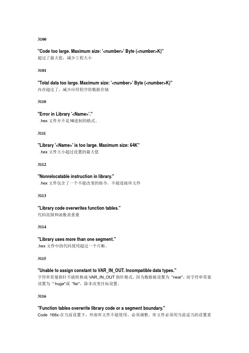
3100"Code too large. Maximum size: '<number>' Byte (<number>K)"超过了最大值,减少工程大小3101"Total data too large. Maximum size: '<number>' Byte (<number>K)"内存超过了,减少应用程序的数据存储3110"Error in Library '<Name>'.".hex文件并不是16进制的格式。
3111"Library '<Name>' is too large. Maximum size: 64K".hex文件大小超过设置的最大值3112"Nonrelocatable instruction in library.".hex文件包含了一个不能改变的指令,不能连接库文件3113"Library code overwrites function tables."代码范围和函数表重叠3114"Library uses more than one segment.".hex文件中的代码使用超过一个片断。
3115"Unable to assign constant to VAR_IN_OUT. Incompatible data types."字符串常量指针不能转换成VAR_IN_OUT指针格式,因为数据被设置为"near",而字符串常量设置为" huge"或"far",除非改变目标设置。
3116"Function tables overwrite library code or a segment boundary."Code 166x:在当前设置下,外部库文件不能使用,必须调整。
电脑开机后出现蓝屏代码全解析
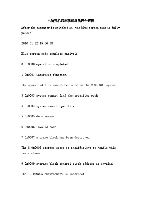
电脑开机后出现蓝屏代码全解析After the computer is switched on, the blue screen code is fully parsed2010-01-22 15:56:38Blue screen code complete analysis0 0x0000 operation completed.1 0x0001 incorrect function.The specified file cannot be found in the 2 0x0002 system.3 0x0003 system cannot find the specified path.4 0x0004 system cannot open file.5 0x0005 deny access.6 0x0006 invalid code.7 0x0007 storage block has been destroyed.The 8 0x0008 storage space is insufficient to handle this instruction.9 0x0009 storage block control block address is invalid.The 10 0x000a environment is incorrect.11, 0x000b attempts to load a malformed program.12 0x000c access code error.13 0x000d data error.14 0x000e storage space is not enough to complete this task.15 0x000f system cannot find the specified disk drive.16 0x0010 cannot remove directory.16 0x0010 cannot remove directory.The 17 0x0011 system cannot move files to another disk drive.18 0x0012 does not have any files.19 0x0013 storage media to write protected state.The specified device cannot be found in the 20 0x0014 system. The 21 0x0015 device is not ready.The 22 0x0016 device is unable to recognize instructions. 23 0x0017 data error (cyclic, redundancy, check)The 24 0x0018 program issues a length error command.The 25 0x0019 disk drive cannot find a fixed sector or trackon disk.26 0x001a specified disk or disk cannot access.27 0x001b disk drive cannot find required sector.The 28 0x001c printer has no paper.The 29 0x001d system cannot write data to the specified disk drive.The 30 0x001e system cannot read the specified device.31 0x001f does not work on a device connected to the system."0x0020 the process cannot access the file because it is being used by another process."Part of the 33 0x0021 file is locked and cannot be accessed now.The disk for the 34 0x0022 disk drive is incorrect. Please insert%2 (volume, serial, number:%3) into disk drive%1.36 0x0024 opens too many shared files.38 0x0026 arrives at the end of the file.The 39 0x0027 disk is full.50 0x0032 does not support this network requirement.51 0x0033 remote computer cannot be used.52 0x0034 network name repetition.53 0x0035 network path cannot be found.54 0x0036 network busy.The "0x0037 the specified network resource or device is no longer available."56, 0x0038, the, network, BIOS, command, limit, has, been, reached.,, 0x0039 network adapter card problems.58 0x003a specified server cannot perform requested job.An unexpected error occurred on the 59 0x003b network.60 0x003c remote adapter card not compatible.The 61 0x003d printer queue is full.The 62 0x003e server space cannot store the files waiting to be printed.63 0x003f waiting for the print file has been deleted.64 0x0040 specified network name cannot be used.65 0x0041 deny access to the network.65 0x0041 deny access to the network.66 0x0042 network resource type error.67 0x0043 network name cannot be found.68 0x0044 exceeds the name limit of the zone computer network adapter card.69 0x0045 exceeds the network BIOS job phase limit.The 70 0x0046 remote server has been paused or is starting.71 0x0047 cannot connect to this remote computer at this time because the number of lines has reached an upper limit.72 0x0048 specified printer or disk device has been suspended.The 80 0x0050 file already exists.82 0x0052 cannot build directories or files.83 0x0053 int 24 failedThe storage body for handling this requirement cannot be used by 84 0x0054.The name of the 85 0x0055 proximal device is already in use.86 0x0056 specified network password error.87 0x0057 parameter error.88 0x0058 network data write error.89 0x0059 the system cannot perform any other travel at this time.100 0x0064 cannot build other system semaphore. 101 0x0065 belongs to other travel specific semaphore.102, 0x0066 semaphore is set and cannot be turned off.103 0x0067 cannot specify semaphore.104 0x0068 cannot request a dedicated semaphore at the turn off time.104 0x0068 cannot request a dedicated semaphore at the turn off time.105 0x0069 the previous ownership of this semaphore is over.106 0x006a, insert the disk into%1.107 0x006b the program has stopped because the alternate disk has not been inserted.The 108 0x006c disk is in use or locked.109 0x006d pipe has been aborted.The 110 0x006e system cannot open the specified device or file.The 111 0x006f file name is too long.112 0x0070 disk space is insufficient.113 0x0071 does not have an internal file identifier available.The internal file identifier for the 114 0x0072 target is incorrect.117 0x0075 the IOCTL call performed by the application is incorrect.118 0x0076 write validation parameter value incorrect.The 119 0x0077 system does not support the required instructions.120 0x0078 this function is valid only in Win32 mode.121 0x0079 semaphore over time period.The data area of the 122 0x007a transmitting to the system call is too small.123 0x007b file name, directory name or storage volume label syntax error.124 0x007c system call level is incorrect.125 0x007d disk is not set.126 0x007e cannot find the specified module.127 0x007f cannot find the specified program.128 0x0080 has no sub itinerary available for waiting.128 0x0080 has no sub itinerary available for waiting.129 0x0081%1 this application cannot be in Win32 mode? Small onion? Br / > 130 0x0082 attempt to use a file handle to an open disk partition for an operation other than raw disk i/o.131 0x0083 attempts to move the file pointer to the beginning of the file.132 0x0084 cannot set the file pointer in the specified device or file.133, 0x0085, join, or subst instructions cannot be used to contain previously bonded disk drives.134 0x0086 attempts to combine disk drives using join or subst instructions.The 135 0x0087 attempts to replace the disk drive in which the join or subst command is used.The 136 0x0088 system attempts to remove the link relationship of an un connected disk drive.The 137 0x0089 system attempts to delete the replacement relation of the alternate disk drive.The 138 0x008a system attempts to combine the disk drive with the directory of the disk drive that has been combined.The 139 0x008b system attempts to replace the disk drive with the directory of the disk drive that has been replaced.The 140 0x008c system attempts to replace the disk drive with the directory of the disk drive that has been replaced.The 141 0x008d system attempts to subst the disk drive into a combined disk drive directory.The 142 0x008e system cannot execute join or subst at the moment.The 143 0x008f system cannot combine disk drives or replace directories under the same disk drive.144 0x0090 this directory is not a subdirectory of the root directory.145, the 0x0091 directory still has data.146 0x0092 specifies the path that has been replaced.147 0x0093 resources are insufficient to handle this instruction.148 0x0094 specified path is not available at this time.148 0x0094 specified path is not available at this time.149 0x0095 attempts to combine or replace the disk drive directory, which has been replaced by the target.The 150 0x0096 config.sys file does not specify system trace information, or the trace function is canceled.151 0x0097 specifies the incorrect number of semaphore events dosmuxsemwait.152 0x0098 dosmuxsemwait did not execute; set too many semaphore.The 153 0x0099 dosmuxsemwait list is incorrect.154 0x009a the length limit of the storage media index you entered.155 0x009b cannot create any other threads.The 156 0x009c receive trip refuses to accept the signal. The 157 0x009d section has been abandoned and cannot be locked. The 158 0x009e section has been unlocked.The address of the 159 0x009f thread identifier is incorrect.The argument string of 160 0x00a0 passed to dosexecpgm is incorrect.161 0x00a1 the specified path is incorrect.162 0x00a2 signal wait processing.The 164 0x00a4 system cannot create threads.167 0x00a7 cannot lock part of the file.The resources requested by 170 0x00aa are in use.The lock requirement for 173 0x00ad cancellation range is not obvious.The 174 0x00ae file system does not support automatic change lock type.180 0x00b4 system found an incorrect section number.The 182 0x00b6 * system cannot execute%1.The 182 0x00b6 * system cannot execute%1.The 183 0x00b7 file already exists. The same file cannot be created.Flag error of 186 0x00ba transfer.187 0x00bb specified system flag can not be found.The 188 0x00bc * system cannot execute%1.The 189 0x00bd * system cannot execute%1.The 190 0x00be * system cannot execute%1.191 0x00bf cannot be in Win32 mode? Onion?%1?.The 192 0x00c0 * system cannot execute%1.193 0x00c1%1 is not the right Win32 application.The 194 0x00c2 * system cannot execute%1.The 195 0x00c3 * system cannot execute%1.The 196 0x00c4 * system cannot execute this application.The 197 0x00c5 * system cannot execute this application at the moment.The 198 0x00c6 * system cannot execute%1.The 199 0x00c7 * system cannot execute this application.The section of the 200 0x00c8 program code must not be greater than or equal to 64kb.The 201 0x00c9 * system cannot execute%1.The 202 0x00ca * system cannot execute%1.The 203 0x00cb system cannot find the input environment option. \\r205 0x00cd in the instruction subdirectory, there is no stroke, there is a signal handler.206 0x00ce file name or extension is too long.207 0x00cf ring 2 stack used.207 0x00cf ring 2 stack used.208 0x00d0 input generic file name * * or incorrect, or specify too many generic file name elements.The signal sent by 209 0x00d1 is not correct.210 0x00d2 cannot set the signal handler.The 212 0x00d4 section is locked and cannot be reconfigured.214 0x00d6 has too many dynamic linking modules attached to this program or dynamic link module.215, 0x00d7, can\'\'t, nest, calls, to, loadmodule.230, 0x00e6, the, pipe, state, is, invalid.231 0x00e7 all pipe instances are busy.232, 0x00e8, the, pipe, is, being, closed.The "0x00e9 no process is on the other end of the pipe." 234 0x00ea has more available information.The 240 0x00f0 operation phase was canceled.254 0x00fe specified extension property name is invalid. 255 0x00ff extension attributes inconsistent.259 0x0103 has no data available.266 0x010a cannot use copy api.267 0x010b directory name error.The 275 0x0113 extended attribute does not apply to buffers.The extended property file of 276 0x0114 on the plug-in file system has been corrupted.277 0x0115 extended attribute table file full.278 0x0116 specified extension property code is invalid. 278 0x0116 specified extension property code is invalid.This file system for 282 0x011a plug-in does not support extended attributes.288 0x0120 intended to release mutex that does not belong to the user.298, 0x012a, semaphore, excessive number of transfers.299 0x012b only completes part of the read/writeprocessmemory requirement.The 317 0x013d system could not find the message located in message file% 2, numbered 0x%1.487 0x01e7 attempts to access invalid addresses.The 534 0x0216 operation results in more than 32 bits.At the other end of the 535 0x0217 channel, there is a stroke in the shuttle data.536 0x0218 waits for the route to open the other end of the channel.994 0x03e2 access extended attribute denied.995 0x03e3 terminates the i/o job unexpectedly because of the end of the thread or application requirements.The 996 0x03e4 overlapped i/o event is not set as notification status.997 0x03e5 is processing overlapping i/o jobs.998 0x03e6 invalid access to memory locations.999 0x03e7 error executing inpage job.Contents that are logged in memory.The 10170 * 000003F9 system attempts to log in to the file loading system or restore the file to the system login, but the format of the specified file is not in the format of the system login file.10180 x 000003FA attempts to log in on the system marked "delete" and perform an illegal operation.10180 x 000003FA attempts to log in on the system marked "delete" and perform an illegal operation.The 10190 * 000003FB system cannot configure the space needed for the system login record.10200 * 000003FC cannot establish symbolic links on the system login code that already has child code or values.10210 * 000003FD cannot establish permanent sub machine code under temporary machine code.Notification of change request of 10220 * 000003FE is completed, but the message is not transmitted through caller's buffer.Callers now need to file their own files to find out where they changed.10510 x 0000041B control has been transferred to other services in a service confrontation.The control required by 10520 * 0000041C is invalid for this service10530 *0000041DTheservicedidnotrespondtothestartorcontrolrequestin atimelyfashion.10540 * 0000041E cannot establish the thread of service.The 10550 * 0000041F service database is locked.10560 * 00000420 of this service is already under way.10570 * 00000421 account name error or not exist.10580 x 00000422 specified service pause function cannot be activated.10590 * 00000423 specifies the loop service affiliation.10600 x 00000424 designated services are not installed services.10610 * 00000425 the service item cannot receive control messages at this point.10620 x 00000426 service is not active yet.10630 x 00000427 cannot connect to the service control program.An unexpected condition occurs when 10640 * 00000428 handles control requirements.The 10650 * 00000429 specified database does not exist.The 10650 * 00000429 specified database does not exist.The 10660 x 0000042A service returns an error code belonging to the service.10670 x 0000042BTheprocessterminatedunexpectedly.10680 * 0000042C dependency service or group cannot be activated.10690 * 0000042D failed to activate the service because the login failed.10700 x 0000042E in the activation after the crash in active service.10710 * 0000042F specified service database locked invalid.The 10720 * 00000430 designated service has been marked for deletion.The 10730 x 00000431 specified service already exists.The 10740 * 00000432 system is currently executing a successful configuration execution.10750 * 00000433 secondary services do not exist or have been marked as deleted.The current activation of 10760 * 00000434 has been accepted for the last successful execution of the control settings.After 10770 x 00000435 activation, there is no activation service.The 10780 * 00000436 specified name is already used for the service name or service display name.11000 x 0000044C has reached the end of the tape.11010 x 0000044D to the file mark.11020 x 0000044E encountered the beginning or division of the tape.11030 x 0000044F to the end of the file group.11040 x 00000450 tape without any information.11050 * 00000451 tape cannot make segmentation.11060 x 00000452 accessing a new volume of a volume, the current block size error is found.Tape partition information is not found when 11070 * 00000453 load the tape.11080 x 00000454 unable to lock the storage media back band function.11080 x 00000454 unable to lock the storage media back band function.11090 x 00000455 cannot load the storage media.The storage media in the 11100 * 00000456 disk drive has been changed.11110 * 00000457 has reset the I/O bus.11120 x 00000458 disk drive without any storage media.11130 x 00000459 target multi-bytecodepage, not corresponding to Unicode characters.11140 * 0000045A dynamic link library (DLL) start routine failed.The 11150 x 0000045B system is shutting down.11160 * 0000045C cannot stop system shutdown because no shutdown is in progress.11170 * 0000045D failed to execute the request because of anerror in the I/O device.The start of the 11180 x 0000045E sequence device failed to cancel the loading sequence driver.11190 * 0000045F cannot open device. This device shares the interrupt request (IRQ) with other devices. At least one other device using the same IRQ has been turned on.11200 x00000460AserialI/Ooperationwascompletedbyanotherwritetothes erialport. (TheIOCTL_SERIAL_XOFF_COUNTERreachedzero.)11210 * 00000461 because sequence time has passed, the sequence I/O job is completed. (IOCTL_SERIAL_XOFF_COUNTER is not zero. )11220 x 00000462 cannot find any ID address on disk.The 11230 * 00000463 disk sector ID field does not match the disk control card tracking address.The 11240 x 00000464 floppy drive control card returns an error that is not recognized by a floppy disk drive driver.The 11250 * 00000465 floppy drive control card returns inconsistent results in the cache.11260 x 00000466 access hard disk failed and can not be done after retry.11270 x 00000467 access hard disk failed and can not be doneafter retry.11280 * 00000468 access to the hard disk, you must reset the disk control card, but even reset the action failed.11290 x 00000469 to the end of the tape.11300 x 0000046A is available and the server has insufficient storage space to handle this instruction.11310 x 0000046B found potential deadlock conditions.11320 * 0000046C specified base address or file displacement is not properly aligned.11400 x 00000474 attempts to change the system power status, but other applications or drivers reject it.11410 * 00000475 system BIOS cannot change the system power status.The 11500 x 0000047E specified program requires a new Windows version.The program specified by 11510 * 0000047F is not a Windows or MS-DOS program.The 11520 x 00000480 specified program has been activated and cannot be activated again.The 11530 x 00000481 specified program is written for the oldversion of Windows.11540 x 00000482, one of the link library files required to perform this application is damaged.11550 * 00000483 no application is associated with the specified file for this job.An error occurred in the 11560 * 00000484 transfer instruction to the application.11570 * 00000485 cannot find the link library file required to execute this application.The name of the device specified in 12000 * 000004B0 is invalid.The 12010 x 000004B1 device is not online yet, but it is a memory online.12020 x 000004B2 device to try to remember.The network path provided by 12030 * 000004B3 cannot find any network provider.The network path provided by 12030 * 000004B3 cannot find any network provider.12040 * 000004B4 specified network provider name error.12050 * 000004B5 cannot open network online settings file.12060 x 000004B6 network online settings file broken.12070 * 000004B7 cannot enumerate non containers.An extension error of 12080 * 000004B8.12090 * 000004B9 specified group name error.12100 * 000004BA specified computer name error.12110 * 000004BB specified event name error.12120 * 000004BC specified network name error.12130 x 000004BD specified service name error.12140 * 000004BE specified network name error.12150 * 000004BF specified resource sharing name error.12160 * 000004C0 specified password error.12170 * 000004C1 specified message name error.12180 * 000004C2 specified message destination error.The condition provided by 12190 * 000004C3 conflicts with the existing condition set.12200 x 000004C4 attempts to connect to the web server, but there is too much online access to the server.12210 * 000004C5 other network computers are already using this workgroup or domain name.The 12220 * 000004C6 network is not shown or activated.12230 * 000004C7 users have cancelled their jobs.The job requested by 12240 * 000004C8 cannot be performed on the file that has opened the user's corresponding section.12250 x 000004C9 remote system refuses to network online.12250 x 000004C9 remote system refuses to network online.12260 * 000004CA shutdown network on line.The 12270 * 000004CB network transmission endpoint already has an associated address.12280 * 000004CC addresses have not yet been associated with network endpoints.12290 * 000004CD attempts to work on a network that does not exist.12300 * 000004CE performs invalid jobs on the network line in action.12310 x 000004CF cannot be transferred to remote network.12320 x 000004D0 cannot be connected to remote system.12330 * 000004D1 remote system does not support transport protocol.The destination network endpoint of the 12340 * 000004D2 remote system does not perform service in execution.12350 * 000004D3 requirements have been discontinued.The 12360 * 000004D4 terminal system has been interrupted and the network is online.12370 * 000004D5 cannot complete the job. Please try again.12380 x 000004D6 cannot connect to the server because this account has reached the upper bound on the number of simultaneous entries.12390 x 000004D7 attempts to log on to the network at this unauthorized time of the account.12400 * 000004D8 this account cannot log in from this network.12410 * 000004D9 network address cannot be used for this requested job.12420 x 000004DA service has been registered.The 12430 x 000004DB specified service does not exist.12440 * 000004DC jobs cannot be performed because the user is not authorized to use them.The job requested by 12450 * 000004DD cannot be performed because the user has not logged on to the network. The specified service does not exist.12460 x 000004DE returns the message that calls the caller to continue working.After 12470 * 000004DF, after completing the start job, try to start the job again.12480 x 000004E0, no other near end device.13000 * 00000514 does not specify all reference rights to callers.There is still no completed online between the 13010 * 00000515 account name and the security identifier.13020 * 00000516 this account does not have a special system quota limit.13030 * 00000517 has no encryption code available. Returns a known cryptographic code.The 13040 * 00000518NT password is too complex to be converted to a LANManager password. The returned LANManager password is an empty string.13050 x 00000519 revision level unknown.13060 * 0000051A indicates incompatibility between the two revision classes.13070 * 0000051B this security identifier cannot be specified as the owner of this object.13080 * 0000051C this security identifier cannot be specified as the primary object group.13090 x0000051DAnattempthasbeenmadetooperateonanimpersonationtoken byathreadthatisnotcurrentlyimpersonatingaclient.13100 * 0000051E cannot close the group.13110 * 0000051F currently has no logon server, so it cannot handle logon requests.13120 * 00000520 specified logon operation phase does not exist. The job phase may already be over.13130 x 00000521 specified permissions do not exist.13130 x 00000521 specified permissions do not exist.The 13140 * 00000522 client does not list required permissions.The name format provided by 13150 * 00000523 does not correspond to the account name.The 13160 x 00000524 specified user already exists.13170 x 00000525 specified user does not exist.A 13180 * 00000526 designated group already exists.13190 * 00000527 designated groups are not saved.The 13200 * 00000528 specified user account is already a member of the specified group, or the specified group cannot be deleted because of the inclusion of members.The 13210 * 00000529 specified user account is not a specified group account member.The management account that was left last time by 13220 * 0000052A cannot be closed or deleted.13230 x 0000052B cannot update password. The password entered is incorrect.13240 x 0000052C cannot update password. The new password entered does not conform to the password requirement.13250 x 0000052D cannot update password because it violates password update rules.13260 * 0000052E logon failed: unrecognized user name or password error.13270 * 0000052F logon failed: user account restriction.13280 * 00000530 logon failure: violation of account logon time limit.13290 * 00000531 logon failed: the user is not allowed to log in to this computer.13300 * 00000532 logon failed: the specified account password expired.13310 * 00000533 logon failed: account is currently invalid.The 13320 * 00000534 account name does not correspond with the account identification number.13330 x 00000535 requires too many user identification codes (localuseridentifiers, LUIDs) at one time.13330 x 00000535 requires too many user identification codes (localuseridentifiers, LUIDs) at one time.13340 x 00000536 does not have a near - end user identifier (localuseridentifiers, LUIDs).The authorization portion of the 13350 * 00000537 security identification code is invalid for this particular usage.13360 * 00000538 invalid access control list structure. 13370 * 00000539 security identification code structure isinvalid.The 13380 * 0000053A security statement substructure is invalid.13400 * 0000053C cannot establish an inherited access control list or access control entry.The 13410 x 0000053D server is currently invalid.13420 x 0000053E server is currently available.The value provided by 13430 * 0000053F is invalid identifier authorization value.13440 * 00000540 has no memory available for security information updates.The 13450 * 00000541 specified attribute is invalid, or the specified attribute is associated with the entire group。
fortran90常见错误

1、运行fortran时出现forrt1:severe<59>:list-directed I/O syntax error,unit 1,file G:\1\1\meat.dat怎么办这是通道1 ,链接到文件meat.dat 的读写出错了。
这问题你得认真检查类似read( 1 , * ) 或write( 1 , * ) 这样的语句,错误原因挺多的。
比如二进制文件用了文本方式读取,比如变量列表与文件不匹配。
问:另外forrt1:severe<161>:program exception -array bounds exceeded是怎么回事?回答:数组越界,也是很常见的错误。
比如real a(100)如果你使用了a(101) 就会越界,因为a 数组只有100 个元素。
2、fortran运行提示error M6201:math-**,现将代码贴出,求高手帮忙看看,急求解答!我不能确定你的错误是怎么引起的。
可能咱们的编译器不同。
你的代码在我这里的问题是:虚参和实参精度不同。
在程序中,你定义了部分real*8,但是对应的虚参和返回值却定义为real。
比如主程序里的z1(双精度),传入函数g里面的x却定义为单精度。
主程序Do 死循环了。
z2_jiashe 和 z2_suan 每一次循环都没有发生改变,于是永远跳不出循环。
我给你的建议是:同一个程序,统一使用real*8 或real*4,尽量不要混用,除非你很自信能理清他们的关系。
检查Do 循环,尤其是z2_jiashe 和z2_suan,是否应该每次循环不同?fortran_排除错误(2012-04-20 23:22:44)安装好VISUAL FORTRAN后1、运行Developer studio即可开始编译FORTRAN程序2、选择File菜单中的New选项3、在弹出的对话框选择projects标签,其他标签不用管,projects格式选用Fortran console application;在project name里命名(最好英文名),点击“ok ”4、接下来画面中,选择“an empty project”,点击“finish”5、接下来画面点击“ok”6、再选择一次File菜单中的new7、对话框选用files标签,选择Fortran free format source file ,并在file里命名8、点击“ok”数Source Files 放源文件(.c、.cpp)程序的实现代码全放在这里Header Files 放头文件(.h)声明放在这里Resource Files 资源文件(.rc)放图标、图片、菜单、文字之类的,主要用来做界面的东东一般都放这里External Dependencies 除上三种以外的,程序编译时用到的文件全放这里fortran内部函数出错信息解释内部函数出错信息解释[sourcefile(line)]run-time error M62××MATH错误号函数级数学错误信息M6201 functionnames:DOMAIN error函数的自变量超出了约定的取值域,例如sqrt(-1)M6202 functionname:SING error无意义的变量。
AEMC微欧姆表模型6255快速参考指南说明书

AEMC Micro-Ohmmeter Model 6255QUICK REFERENCE GUIDEREAD THE USER MANUAL AND COMPLY WITH ALL PRECAUTIONS FOR USELIST OF ERROR CODESErr 1Low battery levelErr 2Internal problemErr 3Unable to measure batteryErr 4Unable to measure temperatureErr 5Internal temperature too high - let the instrument cool downErr 6Unable to establish current measurementErr 7Measurement out of rangeErr 8Internal problemErr 9Measurement cycle stoppedErr 10Temperature sensor incorrectly connected or missingErr 11Current leads incorrectly connectedErr 12Voltage leads incorrectly connected or measured resistancetoo highErr 13Residual voltage too highErr 21Adjustment out of rangeErr 22Measured value out of rangeErr 23Entry out of rangeErr 24Unable to write to memoryErr 25Unable to read memoryErr 26Memory fullErr 27Memory empty; no data availableErr 28Memory check problemErr 29Object or test number incorrectWARNING: If Error message 2, 3, 4, or 8 appears, the instrument must be sent to aqualified organization for repair. See the Repair and Calibration section in the usermanual for return instructions.BUTTON FUNCTIONSAEMC Micro-Ohmmeter Model 6255QUICK REFERENCE GUIDEREAD THE USER MANUAL AND COMPLY WITH ALL PRECAUTIONS FOR USELIST OF ERROR CODESErr 1Low battery levelErr 2Internal problemErr 3Unable to measure batteryErr 4Unable to measure temperatureErr 5Internal temperature too high - let the instrument cool downErr 6Unable to establish current measurementErr 7Measurement out of rangeErr 8Internal problemErr 9Measurement cycle stoppedErr 10Temperature sensor incorrectly connected or missingErr 11Current leads incorrectly connectedErr 12Voltage leads incorrectly connected or measured resistancetoo highErr 13Residual voltage too highErr 21Adjustment out of rangeErr 22Measured value out of rangeErr 23Entry out of rangeErr 24Unable to write to memoryErr 25Unable to read memoryErr 26Memory fullErr 27Memory empty; no data availableErr 28Memory check problemErr 29Object or test number incorrectWARNING: If Error message 2, 3, 4, or 8 appears, the instrument must be sent to aqualified organization for repair. See the Repair and Calibration section in the usermanual for return instructions.BUTTON FUNCTIONSChauvin Arnoux ®, Inc. d.b.a. AEMC ® Instruments15 Faraday Drive, Dover, NH 03820 USA • Phone: (800) 343-1391 • (603) 749-6434*Displays Shown are the Default Conditions99-MAN 100459 v1 01/18Chauvin Arnoux ®, Inc. d.b.a. AEMC ® Instruments15 Faraday Drive, Dover, NH 03820 USA • Phone: (800) 343-1391 • (603) 749-6434*Displays Shown are the Default Conditions99-MAN 100459 v1 01/18AEMC Micro-Ohmmeter Model 6255PROGRAMMING MENUAEMC Micro-Ohmmeter Model 6255PROGRAMMING MENU。
诺西W_RNC常见告警列表及处理方法
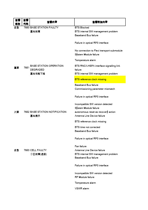
基站故障BTS internal SW management problemBaseband Bus failureFailure in optical RP3 interfaceNo connection to Flexi transport submoduleSystem Module failureTemperature alarm重要7651BASE STATION OPERATION DEGRADE BTS RNC/I-HSPA interface signalling link failure 基站性能下降BTS internal SW management problemBTS reference clock missingBaseband Bus failureCommissioning parameter mismatchFailure in optical RP3 interfaceIncompatible SW version detectedSystem Module failure次要7652BASE STATION NOTIFICATION autonomous reset as recovery action基站提示Antenna Line Device failureBTS reference clock missingBTS time not correctedBaseband Bus failureFailure in optical RP3 interfaceFan failure紧急7653CELL FAULTY Antenna Line Device failure小区故障(退服)BTS internal SW management problemBaseband Bus failureFailure in optical RP3 interfaceIncompatible SW version detectedRF Module failureTemperature alarmVSWR alarm重要7654CELL OPERATION DEGRADED Antenna Line Device failure小区性能下降Antenna Line failureBTS internal SW management problemBaseband Bus failureFailure in optical RP3 interfaceIncompatible SW version detectedRF Module failureRx signal level failureTemperature alarmVSWR alarm次要7655CELL NOTIFICATION Antenna Line Device Operation FailureAntenna Line Device failureBaseband Bus failureHSUPA capacity decreasedIncompatible SW version detected紧急7660BASE STATION LICENCE EXPIRED NONE次要7661BASE STATION LICENCE NOTIFICATIO H W capacity too low for feature <licenceCode>,Licence missing <licenceCode>, <licenceName>重要61151AIS on unit $U, interface $IF NONE重要61104EBER on unit $U, interface $IF NONE重要61500Five failed logins to FTM due to wronguser name or passwordNONE重要61171IMA link out of delay synchronizationon unit $U, interface $IFNONE重要61028LOF on unit $U, interface $IF NONE 重要61029LOS on unit $U, ethernet interface $IF NONE 重要61170Loss of IMA frame on unit $U, interface $IFNONE 重要61152RDI on unit $U, interface $IF NONE 重要7740BEATING WCDMA BTS ALARM NONE次要7750FAILURE IN WCDMA WBTS O&M CONNECTIONNONE重要7761RNW O&M SCENARIO FAILURE NONE 重要7762RNW DATABASE OPERATION FAILURE NONE 重要7771WCDMA CELL OUT OF USE NONE 重要7772HSDPA CONFIGURATION FAILED NONE次要7775INCONSISTENCY IN WCEL CONFIGURATION PARAMETERSNONE重要7776HSDPA FAILURE IN WCEL NONE重要7778WCDMA BTS DEDICATED MEASUREMENT FAILURENONE次要7779RECOVERY ACTIONS ONGOING NONE 重要7780HSUPA FAILURE IN WCEL NONE紧急7781NETWORK ELEMENTCONFIGURATION ERRORNONE重要7782HSUPA CONFIGURATION FAILED NONE重要7783IP BASED D-NBAP LINK FAILURE NONE 重要7784RECOVERY ACTION FAILURE NONE 重要3267AAL TYPE 2 CAC REJECTION LEVEL EXNONE 重要70162RAID ARRAY HAS BEEN DEGRADED NONE 重要70159MANAGED OBJECT FAILED NONE 重要70168CLUSTER STARTED (RESTARTED)NONE 重要2518NO VALID FALLBACK COPY FOR DEFAUNONE基站内部软件包管理问题 1.重启基站 2.更新基站软件包 3.更换故障模块基站基带连线故障 1.检查系统模块与射频模块的连线 2.重启基站 3.更换故障模块系统模块与射频模块之间按的接口故障此故障多发生于拉远小区,处理步骤:1.检查拉远小区的模块是否有电;2.检查系统模块与射频模块间的光路是否正常;3.更换损坏的光纤或者光电模块;4.重启基站;5.更换故障模块基站传输板连接中断 1.重启基站 2.更换故障传输板系统模块故障重启系统模块,如果不能恢复,则更换系统模块温度告警1.检查环境温度是否过高或过低 2.重启产生告警的模块 3.更换产生告警的模块BTS与RNC间的AAL2信令中断引发此告警的最常见原因是传输闪断,检查传输状况 基站内部软件包管理问题 1.重启基站 2.更新基站软件包 3.更换故障模块基站参考时钟丢失基站上一般设置第1&2条传输为时钟源,如果1&2条传输均断,则触发此告警。
德力西JD-5S 电动机综合保护器 说明书

JD-5S Series Electric Motor Integrated ProtectorUser Manual□Please carefully read this User Manual before the installationand operation of this product, and keep it properly for futurereferenceI. Overview1.1 Scope of ApplicationJD-5S series electric motor integrated protector is used in the AC 50/60Hz power supply circuit with a voltage 380V and below to form an electric motor control circuit together with the switching circuits such as AC contactor. if found abnormal working states such as open phase, overload, and stall of main circuit of electric motor, please disconnect the contact of the switching device and cut off the three-phase power supply of electric motor timely to protect the electric motor reliably. JD-5S is an upgraded product of JD-5 product, and the setting current of the protector is set directly according to the rated current marked on the nameplate of the electric motor before use for convenient operation by users; there are technologies of multiple starting timeout options and the overload protection has inverse time limit performance, the needs of various types of motors starting from light load to heavy load can be adapted. The product has functions that there is a digital tube do display the setting current value, the run and fault status light-emitting tube is used to display, and there is pointer ammeter drive output.Standard: GB/T 14048.41.2 Model definitionRated control supply voltage Us:AC220V;AC380VRated current: 1A~9.9A10A~99ASpecification codeElectric motor integrated protectors1.3 Normal working conditions and installation conditions1.3.1 Working environment: the altitude does not exceed 2000 meters; The ambient temperature is not higher than +40℃and not below than -5℃; the voltage change range of the rated control power supply is 85%-110% of the rated voltage; the product is installed in places where the medium has no serious vibration and explosion hazard, and there are no gases and dust in the medium sufficient to cause corrosion to the metals and damage to the insulation, and there is rain and snow invasion.1.3.2 Vertical or horizontal installationII. Structural Characteristics and Working PrincipleJD-5S electric motor integrated protector has protections for overload, stall, thermal memory, open phase, three-phase imbalance, and start-up timeout. This protector adopts current sensing technology, and has a relay output interface; the whole series is of the core-through type. This protector has advantages of simple structure, reliable action, and convenient operation.III. Technical ParametersRated operating current Ie range 1A~9.9A 10A~99ARated insulation voltage, Ui AC380VRated operating voltage, Ue AC380VRated control supply voltage, Us AC50/60Hz AC220V AC380VUse category Main circuit AC-3; matched auxiliary contact (body) AC-15 Shell protection grade IP40Number of types of contacts of aux.circuit1 normally openOperating voltage and operating currentunder the use category of aux. CircuitAC-15 Ue: AC220V Ie: 0.47ARated ultimate short circuit current matedSCPDRT16-00, 6ATrip level 10A, 10, 20, 30Overload protection characteristics When the actual operating current of the motor is 1.05 times of the rated operating current, the protector operation protection time is greater than or equal to 2 h; when the actual operating current rises to 1.2 times, the protector operation protection time is less than 2 h; when the actual operating current rises to 1.5 times, the protector operation protection time is less than 2 min.Range of matched DC meter head(Rated current) 0~5A (1A~4A); 0~10A (4A~10A); 0~50A (10A~40A);0~100A (40~99A)Phase open time The open time of any phase among three phases is ≤ 3s Contact capacity AC380V, 3A; AC220V, 5A (Resistive)Electrical life: ≥10 x 104 timesMechanical life ≥100 x 104 timesInstallation method Device type (with TH35 mounting rail or screw fixed installation)IV. Outline and Installation Dimensions of ProductElectric motor integrated protectorConnected to meter headConnected to meter head Notes: QA: Start Notes: QA: StartTA: Stop TA: StopKM: AC contactor 220V KM: AC contactor 380VV. Installation and Operation InstructionsInstallation and Operation Instructions:1. Please carefully read the instructions, and connect the wires according to the wiring diagram.2. 1# and 2# terminals are the working power input terminals of the protector; 3# and 4# are the normally open contacts at the control end; 5# and 6# can be connected to the pointer ammeter head. The wiring connection method can refer to the wiring diagram; three wires from the outlet end of the AC contactor are pass through three white wire holes H1, H2, and H3 of the protector to connect to the inlet wires of the electric motor (see wiring diagram).3. Operation Guide3.1 Parameter settings1) Motor rated current settingBefore starting the electric motor, power on the JD-5S protector, press the "SET" key to switch to the "Rated current" setting item, and at this time the indicator is lit and the display value on the digital tube is the setting rated current. (According to the nominal rated current value marked on the motor nameplate, the rated current is set by pressing the "" and "" add and subtract keys)2) Starting timeout protection time settingBefore starting the electric motor, power on the JD-5S protector, press the "SET" key to switch to the "Start time" setting item, and at this time the indicator is lit and the display value on the digital tube is the setting starting timeout protection time (second); set the starting timeout protection time by pressing the "" and "" add and subtract keys; when "OF" is displayed on the digital tube, this indicates that the starting timeout protection is disabled, and when the digit is displayed, this indicates that the starting timeout protection is enabled.The factory default of the product is "OF" to turn off starting timeout protection.3) Trip level settingBefore starting the electric motor, power on the JD-5S protector, and press and hold the "SET" key to switch to the "Trip level" setting item, and at this time the indicator is lit, and the digital tube displays the protection trip level to be set; if "10." is displayed, this indicates Level 10A, with "10" displayed to indicate Level 10, with "20" displayed to indicate Level 20, and with "30" displayed to indicate Level 30. By pressing the "" and "" keys, set the different trip levels. The factory default is "10." indicating Level 10A.4) Failsafe status view and status recovery:When the failsafe protection trips in the event of starting timeout, overload, open phase or unbalance in the line, the fault status indicator on the JD-5S protector panel will be lit, and at this time the protector contact opens and is locked at the OFF state; by pressing the "SET" key, the three-phase current when the trip protection works can be viewed on the external pointer ammeter. If the digital tube displays "A-", this is the trip current of phase a; if "B-" is displayed, this is the trip current of phase B; if "C-" is displayed, this is the trip current of phase C. When the line works normally, press the "RST" key to unlock the current lock state (in case of open phase, unbalance, or starting timeout, press the "RST" key for unlocking). As the overload protection has the thermal memory function, pressing the "RST" key cannot realize the unlocking action, and the unlocking will be carried out automatically when the electric motor is cooled down (also, the protector can be powered on again for unlocking).VI. Operation Precautions1. Connect the wire properly according to the wiring diagram.2. Set the setting current according to the rated current marked on the nameplate of electric motor by combining with the display on the digital tube via keys.3. During the startup of electric motor, the overload indicator will be lit. After startup, the overload indicator shall be off during normal operation, so that the adjustment process is completed.4. Please check the performance of the protector regularly, such as open phase test and overload test.5. It is strictly prohibited to increase the current of the protector when the current and electric motor or the load works abnormally, otherwise this may cause the electric motor burns.6. The equipment that may cause major economic losses or personal safety shall be designed to ensure that the technical characteristics and performance values have sufficient margins, and safety measures such as double circuit protection should be taken.VII. Common Faults and Solutions1. If the motor stops during normal operation, carefully check the electric motor for open phase or overload. First check whether the electric motor has very high temperature rise; if found temperature rise, the overload may occur; if not found temperature rise, the line may have open phase to cause trip; check whether the three-phase power supply works normally; check the moving and fixed contacts of the AC contactor have good contact; check whether three power lines of electric motor are loose; If all are normal but the electric motor still fails to start, please carefully check whether the connecting screws of the self-lock contact of AC contactor and the normally-closed contact of protector are loose; the electric motor can start only after all faults are eliminated. Do not start the product forcedly when the fault is not eliminated to prevent accidents.2. The protector works with the electric motor and the load switch (such as contactor), and the power supply shall be turned on simultaneously. If failed to realize the synchronized power-on, the protector may have open phase fault, and the electric motor cannot start normally.3. If found any product failure, please disconnect the power supply, and then find the cause of fault; after checking that the line works normally, operate the product according to the installation and operation instructions.4. For products with poor quality, please contact the local dealer company or our company.VIII. Transport and StorageThe product is not affected by rain and snow during storage and transportation, and cannot be extruded; the product shall be put in a well-ventilated environment during storage, and the relative humidity does not exceed 90% at (25℃± 5℃). The lower temperature limit is -25℃, and the upper temperature limit is +55℃.IX. Unpacking and InspectionUnpack the outer carton, and check there is a user manual in the packing box.X. Ordering NoticeThe current specification is 1A~9.9A, 10~99A. Please note that the power of electric motor shall be consist with that of the protector.When ordering, please specify the model and specification of the product. For special requirements, please contact the manufacturer.VI. Company’s CommitmentUnder the premise that users follow the use and storage conditions and the product are well sealed, within 24 months from the production date, our company will provide repair and replacement service free of charge for any damage or abnormal operation due to poor manufacture quality. A paid repair will be provided if the warranty period expires. For any damage due to one of the following situations, a paid repair will be given even if within the warranty period:(1)Improper operation, maintenance, or storage;(2)Modified and inappropriate repair without permission;(3)Damage due to falling off or during installation after purchase;(4)Force majeure such as earthquakes, fires, lightning strikes, abnormal voltages, and secondary disasters.(5)The electrical life of the product exceeds 100,000 times; the mechanical life of the product exceeds one million times.If you have any questions, please contact the dealer or our company’s customer service department.Customer Service Hotline: 400-826-8008Certificate DELIXI GROUP CO., LTD. Name: Integrated Protector for Electric Motors Model: JD-5S seriesThis product complies with the standard GB/T 14048.4, passes the inspection and is allowed to be shipped. Inspector: Check 01Inspection date: See label on inner boxManufacturer: Delixi Group Co., Ltd.Address: No. 155, Zhandong Road, Liushi Town, Yueqing City, Zhejiang Province P.C.: 325604 Tel: (86-577) 6177 8888Fax: (86-577) 6177 8000Customer Service Hotline: 400-826-8008The second edition of this User Manual was issued in Aug. 2021。
scjp考题1(详尽答案)
scjp考题1(详尽答案)本文Matrix永久镜像:说明:本文可能由Matrix原创,也可能由Matrix的会员整理,或者由Matrix的Crawler在全球知名Java或者其他技术相关站点抓取并永久保留镜像,Matrix会保留所有原来的出处URL,并在显著地方作出说明,如果你发觉出处URL有误,请联系Matrix改正.好资源共享,这份考题有详尽答案,部分题目还有本人心得。
这是试题1。
1. What will happen when you attempt to compile and run the following code?(Assume that the code is compiled and run with assertions enabled.)public class AssertTest{public void methodA(int i){assert i >= 0 : methodB();System.out.println(i);}public void methodB(){ //无返回值System.out.println("The value must not be negative");}public static void main(String args[]){AssertT est test = new AssertTest();test.methodA(-10);}}A.it will print -10B.it will result in AssertionError showing the message-“the value must not be negative”.C.the code will not compile.D.None of these.C is correct. An assert statement can take any one of these two forms -assert Expression1;assert Expression1 : Expression2;Note that, in the second form; the second part of the statement must be an expression- Expression2. In this code, the methodB() returns void, which is not an expression and hence it results in a compile time error. The code will compile if methodB() returns any value such as int, String etc.Also, in both forms of the assert statement, Expression1 must have type boolean or a compile-time error occurs.2. What will happen when you attempt to compile and run the following code?public class Static{static{int x = 5; //在static内有效}static int x,y; //初始化为0public static void main(String args[]){x--; //-1myMethod();System.out.println(x + y + ++x);}public static void myMethod(){y = x++ + ++x; //y=-1+1 x=1}}piletime errorB.prints: 1C.prints: 2D.prints: 3E.prints: 7F.prints: 8D is the correct choice. The above code will not give any compilation error. Note that "Static" is a valid class name. Thus choice A is incorrect.In the above code, on execution, first the static variables (x and y) will be initialized to 0. Then static block will be called and finally main() method will be called. The execution of static block will have no effect on the output as it declares a new variable (int x).The first statement inside main (x--) will result in x to be -1. After that myMethod() will be executed. The statement "y = x++ + ++x;" will be evaluated to y = -1 + 1 and x will become 1. In case the statement be "y =++x + ++x", it would be evaluated to y = 0 + 1 and x would become 1. Finally when System.out is executed "x + y + ++x" will be evaluated to "1 + 0 + 2" which result in 3 as the output. Thus choice D is correct.3. Given the following code, what will be the output?class Value{public int i = 15;}public class Test{public static void main(String argv[]){Test t = new Test();t.first();}public void first(){int i = 5;Value v = new Value();v.i = 25;second(v, i);System.out.println(v.i);}public void second(Value v, int i){i = 0;v.i = 20;Value val = new Value();v = val;System.out.println(v.i + " " + i);}}A.15 0 20B.15 0 15C.20 0 20D.0 15 20A is correct. When we pass references in Java what actually gets passed is the value of that reference (i.e. memory address of the object being referenced and not the actual object referenced by that reference) and it gets passed as value (i.e a copy of the reference is made). Now when we make changes to the object referenced by that reference it reflects on that object even outside of the method being called but any changes made to the reference itself is not reflected on that reference outside of the method which is called. In the example above when the referencev is passed from method first() to second() the value of v is passed. When we assign the value val to v it is valid only inside the method second() and thus inside the method second() what gets printed is 15 (initial value of i in the object referenced by val), then a blank space and then 0 (value of local variable i). After this when we return to the method first() v actually refers to the same object to which it was referring before the method second() was called, but one thing should be noted here that the value of i in that object (referred by v inside the method first()) was changed to 20 in the method second() and this change does reflect even outside the method second(), hence 20 gets printed in the method first(). Thus overall output of the code in consideration is15 0204. What will happen when you attempt to compile and run the following code?class MyParent {int x, y;MyParent(int x, int y){this.x = x;this.y = y;}public int addMe(int x, int y){return this.x + x + y + this.y;}public int addMe(MyParent myPar){return addMe(myPar.x, myPar.y);}}class MyChild extends MyParent{int z;MyChild (int x, int y, int z){super(x,y);this.z = z;}public int addMe(int x, int y, int z){return this.x + x + this.y + y + this.z + z; }public int addMe(MyChild myChi){ return addMe(myChi.x, myChi.y, myChi.z); }public int addMe(int x, int y){return this.x + x + this.y + y;}}public class MySomeOne{public static void main(String args[]){ MyChild myChi = new MyChild(10, 20, 30); MyParent myPar = new MyParent(10, 20); int x = myChi.addMe(10, 20, 30);int y = myChi.addMe(myChi);int z = myPar.addMe(myPar);System.out.println(x + y + z);}}A.300B.240C.120D.180pile errorF.none of the aboveA is the correct choice. In the above code, MyChild class overrides the addMe(int x, int y) method of the MyParent class. And in both the MyChild and MyParent class, addMe() method is overloaded. There is no compilation error anywhere in the above code.On execution, first, the object of MyChild class will be constructed. Please note that there is a super() call from the constructor of MyChild class, which will call the constructor of MyParent class. This will cause the value of z variable of MyChild class to be 30 and x, y variables of MyParent class will become 10 and 20 respectively. The next statement will again call the constructor of MyParent class with same x and y values. This is followed by execution of addMe() method of MyChild class with x as 10, y as 20 and z as 30. Also x and y are inherited by MyChild class from the MyParent class. Thus in the addMe() method of the MyChild class, the value of this.x will be 10, this.y will be 20 and this.z will be 30. The return value of this method will be "10 + 10 + 20 + 20 + 30 + 30", which is equal to 120. Thus x will become 120.This is followed by the invocation of the other addMe() method which takes object reference of the MyChild class. From this method, the method which was called earlier is invoked. This call is exactly the same as the earlier one. Thus the value of y will also be 120 like x.Now the addMe() method of MyParent class is invoked. This method invokes another addMe() method of the same class. Itsequivalent to the invocation of addMe(int x, int y) method with x as 10 and y as 20. Also the value of instance variables x and y of My Parent class is 10 and 20 respectively. The value of z will be evaluated to "10 + 10 + 20 + 20", which is equal to 60. Thus the value of x, y and z after all the invocations will be 120, 120 and 60 respectively. As a result of this finally, "120 + 120 + 60" which is equal to 300 will be printed. Thus A is the correct choice.5. The class AssertionError has "is -a" relationship with these classes (choose two)A.RuntimeExceptionB.ErrorC.VirtualMachineErrorD.IllegalAccessExceptionE.ThrowableB and E are correct. The class AssertionError is an Error, which denotes an “incorrect condition” as opposed to an“unusual condition” (Exception). Since, the class Error descends from Throwable, AssertionError also has “is-a” relationship with Throwable. Here is the hierarchy –ng.Object|+ng.Throwable|+ng.Error Exception| |+ng.AssertionError +RuntimeException IOExceptionWant to know more?You can find more information about this as an answer to the question - “Why is AssertionError a subclass of Error rather thanRuntimeException?” at - /j2se/1.4/docs/guide/lang/assert.html #design-faq-error6. What will be the result of executing the following code?1. boolean a = true;2. boolean b = false;3. boolean c = true;4. if (a == true)5. if (b == true)6. if (c == true) System.out.println("Some things are true in this world");7. else System.out.println("Nothing is true in this world!");8. else if (a && (b = c)) //这里是赋值,不是比较System.out.println("It‘s too confusing to tell what is true and what is false");9. else System.out.println("Hey this won‘t compile");A.The code won’t compile.B.“some things are true in this world” will be printedC.“hey this won’t compile” will be printedD.None of theseD is correct. This is a very good question to test the concepts of execution flow in case of if conditions. The rule for attaching else statements with if conditions is the same as attaching close brackets with open brackets. A close bracket attaches with the closest open bracket, which is not already closed. Similarly an else statement attaches with the closest if statement, which doesn‘t have an else statement already, attached to it. So the else statement at line 7 attaches to the if statement at line 6. The else statement at line 8 attaches to the if statement at line 5. The else statement at line 9 attaches to the if statement at line 8.Now let‘s look at the execution. At line 4 since a is equal to true the execution falls to line 5. At line 5 since b is not true the execution goes to the corresponding else statement at line 8. Now it evaluates the condition inside the if statement. Please note here that an assignment statement also has a value equal to the value being assigned, hence (b = c) evaluates to true and subsequently a && (b = c) ev aluates to true and "It‘s too confusing to tell what is true and what is false" will be printed. Hence the correct answer is choice D.7. What will happen when you attempt to compile and run the following code?interface MyInterface{}public class MyInstanceTest implements MyInterface{static String s;public static void main(String args[]){MyInstanceT est t = new MyInstanceTest();if(t instanceof MyInterface){System.out.println("I am true interface");}else {System.out.println("I am false interface");}if(s instanceof String){System.out.println("I am true String");}else {System.out.println("I am false String");}}}pile time errorB.runtime errorC.prints: “I am true interface” followed by “I am true String”D.prints: “I am false interface” followed by “I am false String”E.prints: “I am true interface” followed by “I am false String”F.prints: “I am false interface” followed by “I am true String”E is the correct choice. The "instanceof" operator tests the class of an object at runtime. It returns true if the class of the left-hand argument is the same as, or is some subclass of, the class specified by the right-hand operand. The right-hand operand may equally well be an interface. In such a case, the test determines if the object at left-hand argument implements the specified interface.In the above case there will not be any compiletime or runtime error. The result of "t instance of MyInterface" will be true as "t" is the object of MyInstanceTest class which implements the MyInstance interface. But the result of "s instanceof String" will be false as "s" refers to null. Thus the output of the above program will be : "I am true interface" followed by " I am false String". Thus choice E is correct and others are incorrect.8. What results from attempting to compile and run the following code?public class Ternary{public static void main(String args[]){int a = 5;System.out.println("Value is - " + ((a < 5) ? 9.0 : 9));}}A.print:Value is -9B.print:Value is -5pilation errorD.None of theseD is correct. The code compiles successfully. In this code the optional value for the ternary operator, 9.0(a double) and 9(an int) are of different types. The result of a ternary operator must be determined at the compile time, and here the type chosen using the rules of promotion for binary operands, is double. Since the result is a double, the output value is printed in a floating point format. The choice of which value to be printed is made on the basis of the result of the comparison "a < 5" which results in false, hence the variable "a" takes the second of the two possible values, which is 9, but because the result type is promoted to double, the output value is actually written as 9.0, rather than the more obvious 9, hence D is correct.9. In the following pieces of code, A and D will compile without any error. True/False?A: StringBuffer sb1 = "abcd";B: Boolean b = new Boolean("abcd");C: byte b = 255;D: int x = 0x1234;E: float fl = 1.2;TrueFalseThe code segments B and D will compile without any error.A is not a valid way to construct a StringBuffer, you need to creata StringBuffer object using "new". B is a valid construction of a Boolean (any string other than "true" or "false" to the Boolean constructor will result in a Boolean with a value of "false"). C will fail to compile because the valid range for a byte is -128 to +127 (ie, 8 bits,signed). D is correct, 0x1234 is the hexadecimal representation in java. E fails to compile because the compiler interprets 1.2 as a double being assigned to a float (down-casting), which is not valid. You either need an explicit cast (as in "(float)1.2") or "1.2f", to indicate a float.10. Considering the following code, Which variables may be referenced correctly at line 12?1.public class Outer2.{3.public int a = 1;4.private int b = 2;5.public void method(final int c)6.{7.int d = 3;8.class Inner9.{10.private void iMethod(int e)11. {12.13.}14.}15.}16.}a b c d eA, B, C and E are correct. Since Inner is not a static inner class,it has a reference to an enclosing object, and all the variables of that object are accessible. Therefore A and B are correct, even if b is private. Variables in the enclosing method are only accessible when they are marked as final hence c is accessible but not d. E is obviously correct as it is a parameter to the method containing line 12 itself.11. What will be the result of executing the following code?public static void main(String args[]){char digit = ‘a‘;for (int i = 0; i < 10; i++){switch (digit){case ‘x‘ :{int j = 0;System.out.println(j);}default :{int j = 100;System.out.println(j);}}}int i = j;System.out.println(i);}A.100 will be printed 11 times.B.100 will be printed 10 times and then there will be a runtime exceptionC.The code will not compile because the variable i cannot be declared twice within the mani() method.D.The code will not compile because the variable j cannot be declared twice within the switch statement.E.None of these.E is correct. The code will not compile. There is no problem with the declaration of another variable i as both the variables are in disjoint blocks (first one is inside the for loop and its scope ends with the for loop, whereas the second is outside the for loop) and, therefore, different scopes and hence valid. The problem is with the variable j. The two declarations of the variable j are perfectly valid as they are in disjoint blocks and, therefore, different scopes. The error is that both the declarations of j are not available outside the case or default statement, whereas we are trying to assign it to the variable i. Therefore the compiler objects and reports variable j not found.12. Which of the following collection classes from java.util package are Thread safe?A.VectorB.ArrayList //与Vector类似,只是不同步C.HashMapD.HashtableA and D are correct. Vector and Hashtable are two collection classes that are inherently thread safe or synchronized; whereas, the classes ArrayList and HashMap are unsynchronized and must be "wrapped" via Collections.SynchronizedList or Collections.synchronizedMap if synchronization is desired.13. What will happen when you attempt to compile and run the following code?class MyThread extends Thread{public void run(){System.out.println("MyThread: run()");}public void start(){System.out.println("MyThread: start()");}}class MyRunnable implements Runnable{public void run(){System.out.println("MyRunnable: run()");}public void start(){System.out.println("MyRunnable: start()");}}public class MyTest {public static void main(String args[]){MyThread myThread = new MyThread();MyRunnable myRunnable = new MyRunnable();Thread thread = new Thread(myRunnable); myThread.start();thread.start();}}A.prints: MyThread: start() followed by MyRunnable: run()B.prints: MyThread: run() followed by MyRunnable: start()C.prints: MyThread: start() followed by MyRunnable: start()D.prints: MyThread: run() followed by MyRunnable: run()pile time errorF.None of the aboveA is the correct choice. In the above code there is not anycompilation error. Thus choice E is incorrect. Inside main() method, objects of MyThread and MyRunnable class are created followed by creation of Thread with object of MyRunnable class.Note that MyThread class extends Thread class and overrides the start() method of the Thread class. Thus on execution of "myThread.start()" statement, the start() method of the MyThread class will be executed and as a result "MyThread:start()" will be printed. Had the start() method not there in MyThread class, the start() method of the Thread class would be called which in turn would call the run() method of the MyThread class.On execution of "thread.start();", the start() method of the Thread class would be called which in turn will call the run() method of the class which is passed to Thread constructor (i.e. MyRunnable class). Thus "MyRunnable:run()" will be printed out. Thus choice A is correct.14. What will be the result of executing the following code?// Filename; SuperclassX.javapackage packageX;public class SuperclassX{protected void superclassMethodX(){}int superclassVarX;}// Filename SubclassY.java1.package packageX.packageY;2.3.public class SubclassY extends SuperclassX4.{5.SuperclassX objX = new SubclassY();6.SubclassY objY = new SubclassY();7.void subclassMethodY()8.{9.objY.superclassMethodX();10.int i;11.i = objY.superclassVarX;12.}13.}pile error at line 5.pile error at line 9.C.Runtime exception at line 11.D.None of theseD is correct. When no access modifier is specified for a member, it is only accessible by another class in the package where its class is defined. Even if its class is visible in another package, the member is not accessible there. In the question above the variable superclassVarX has no access modifier specified and hence it cannot be accessed in the packageY even though the class SuperclassX is visible and the protected method superclassMethodX() can be accessed. Thus the compiler will raise an error at line 11.15. Consider the class hierarchy shown below:FourWheeler(implements DrivingUtilities)/ / \ \/ / \ \/ / \ \/ / \ \/ / \ \Car Truck Bus CraneConsider the following code below:1.DrivingUtilities du;2.FourWheeler fw;3.Truck myTruck = new Truck();4.du = (DrivingUtilities)myTruck;5.fw = new Crane();6.fw = du;Which of the statements below are true?A.Line 4 will not compile because an interface cannot refer to an object.B.The code will compile and run.C.The code will not compile without an explicit cast at line 6, because going down the hierarchy without casting is not allowed.D.The code at line 4 will compile even without the explicit cast.E.The code will compile if we put an explicit cast at line 6 but will throw an exception at runtime.C andD are correct. A and B are obviously wrong because there is nothing wrong in an interface referring to an object. C is correct because an explicit cast is needed to go down the hierarchy. D is correct because no explicit cast is needed at line 4, because we are going up the hierarchy.E is incorrect because if we put an explicit cast at line 6, the code will compile and run perfectly fine, no exception will be thrown because the runtime class of du (that is Truck) can be converted to type FourWheeler without any problem.16. What results from the following code?1.class MyClass2.{3.void myMethod(int i) {System.out.println("int version");}4.void myMethod(String s) {System.out.println("String version");}5.public static void main(String args[])6.{7.MyClass obj = new MyClass();8.char ch = ‘c‘;9.obj.myMethod(ch);10.}11.}A.Line 4 will not compile as void method can’t e overridden.B.An exception at line 9.C.Line 9 will not compile as there is no version of myMethod which takes a char as argument.D.The code compiles and produces output: int versionE.The code compiles and produces output: String versionD is correct. A is incorrect as void methods can be overridden without any problem. B is incorrect as char ch declaration is valid.C is incorrect as char type in java is internally stored as integer and there is a method which takes int as an input.D is correct, on line 9 char ch is widened to an int and passed to int version of the myMethod().E is incorrect as int version of myMethod() is called.17. What is the result when you compile and run the following code?public class ThrowsDemo {static void throwMethod() {System.out.println("Inside throwMethod.");throw new IllegalAccessException("demo");}public static void main(String args[]) {try {throwMethod();} catch (IllegalAccessException e) {System.out.println("Caught " + e);}}}pile errorB.runtime errorpile successfully, nothing is printed.D.inside throwMethod followed by caught: ng.IllegalAccessException: demoA is correct. Exception :ng.IllegalAccessExcption must be caught or placed in the throws clause of the throwMethod(), i.e. the declaration of throwMethod() be changed to "static void throwMethod() throws IllegalAccessExcption". Thus compilation error will occur.18. What will be printed when you execute the following code?class X {Y b = new Y();X() {System.out.print("X");}}class Y {Y() {System.out.print("Y");}}public class Z extends X {Y y = new Y();Z() {System.out.print("Z");}public static void main(String[] args) {new Z();}}A.ZB.YZC.XYZD.YXYZD is correct. A difficult but a fundamental question, please observe carefully. Before any object is constructed the object of the parent class is constructed(as there is a default call to the parent‘s constructor from the constructor of the child class via the super() statement). Also note that when an object is constructed the variables are initialized first and then the constructor is executed. So when new Z() is executed , the object of class X will be constructed, which means Y b = new Y() will be executed and "Y" will be printed as a result. After that constructor of X will be called which implies "X" will be printed. Now the object of Z will be constructed and thus Y y = new Y() will beexecuted and Y will be printed and finally the constructor Z() will be called and thus "Z" will be printed. Thus YXYZ will be printed.19. What will happen when you attempt to compile and run the following code snippet?Boolean b = new Boolean("TRUE"); //不区分大小写if(b.booleanValue()){System.out.println("Yes : " + b);}else{System.out.println("No : " + b);}A.The code will not compile.B.It will print – Yes: trueC.It will print – Yes: TRUED.It will print – No: falseE.It will print – No: FALSEB is the correct choice. The wrapper class Boolean has the following constructor -public Boolean(String s) It allocates a Boolean object representing the value true if the string argument is not null and is equal, ignoring case, to the string "true". Otherwise, allocate a Boolean object representing the value false.E.g.new Boolean("TRUE") produces a Boolean object that represents true.new Boolean("anything") produces a Boolean object that represents false.The internal toString() representation of this object produces the boolean value string in lower case, hence it prints "Yes : true" instead of "Yes : TRUE".20. What is the result when you compile and run the following code?public class Test{public void method(){for(int i = 0; i < 3; i++) {System.out.print(i);}System.out.print(i);}}A. 0122B. 0123C. compile errorD. none of theseC is correct. The code on compilation will give compile time error because the scope of variable i is only within "for" loop.21. What will happen when you attempt to compile and run the following code?int Output = 10;boolean b1 = false;if((b1 == true) && ((Output += 10) == 20)){System.out.println("We are equal " + Output);}else{System.out.println("Not equal! " + Output);}pile errorpile and output of “we are equal 10”pile and output of “not equal!20”pile and output of “not equal!10”D is correct, according to short logic operator rule22. What will be the result of executing the following code?Given that Test1 is a class.1. Test1[] t1 = new Test1[10];2. Test1[][] t2 = new Test1[5][];3. if (t1[0] == null)4. {5.t2[0] = new Test1[10] ;6.t2[1] = new Test1[10];7.t2[2] = new Test1[10];8.t2[3] = new Test1[10];9.t2[4] = new Test1[10];10. }11. System.out.println(t1[0]);12. System.out.println(t2[1][0]);A. The code will not compile because the array t2 is not initialized in an unconditional statement before use.B. The code will compile but a runtime exception will be thrown at line 12.C. The code will compile but a runtime exception will be thrown at line 11.D. None of theseD is correct. Though we cannot use local variables without initializing them (compilation error), there is an exception to it. In case of arrays initialization is supposed to be complete when we specify the leftmost dimension of the array. The problem occurs at runtime if we try to access an element of the array which has not been initialized (specification of size). In the question above the array t2 is initialized before use, therefore there will be no。
The interaction of internal and external information in a problem solving task
The Interaction of Internal and ExternalInformation in a Problem-Solving TaskJiajie ZhangDecember 1990Report 9005Department of Cognitive ScienceUniversity of California, San DiegoLa Jolla, California 92093This research was supported by a grant to Donald Norman and Edwin Hutchins from the Ames Research Center of the National Aeronautics & Space Agency, Grant NCC 2-591 in the Aviation Safety/Automation Program, technical monitor, Everett Palmer. Additional support was provided by funds from the Apple Computer Company and the Digital Equipment Corporation to the Affiliates of Cognitive Science at UCSD.This paper was developed in the environment of the Distributed Cognition Research Group led by Don Norman and Ed Hutchins. I am very grateful to Don Norman for his guidance and extensive conceptual and editorial help in every phase of this project. I thank Ed Hutchins for many inspiring comments and insights during and after these studies. Thanks are also extended to Mark St. John for many constructive criticisms on an early draft; David Kirsh, Tove Klausen, and Hank Strub for helpful discussions; and Richard Warren for his assistance in Experiments 2A and 2B. Requests for reprints should be sent to Jiajie Zhang, Department of Cognitive Science 0515; University of California, San Diego; La Jolla, California, 92093, USA. Email: jzhang@.Copyright © 1990 by Jiajie Zhang. All rights reserved.The Interaction of Internal and External Information in a Problem-Solving TaskJIAJIE ZHANG ABSTRACTIn these studies I examine the role of distributed cognition in problem solving. The major hypothesis explored is that intelligent behavior results from the interaction of internal cognition, external objects, and other people, where a distributed cognitive task can be represented as a set of modules, some internal and some external. The Tower of Hanoi problem is used as a concrete example for these studies. In Experiment 1 I ex-amine the effects of the distribution of rep-resentations among internal and external modules on problem-solving behavior. Experiments 2A and 2B focus on how the nature and number of rules affect problem-solving behavior. Experiment 3 investigates how a group’s problem-solving behavior is affected by the distribution of representations among the individuals. The results of all studies show that distributed cognitive activities are produced by the interaction among the representations in the modules involved in a given task: between internal and external representations and between internal representations. External representations are not peripheral aids. They are an indispensable part of cognition. Two of the factors determining the performance of a distributed cognitive system are the structure of the abstract task space and the distribution of representations across modules.INTRODUCTIONThe traditional approach to cognition in general and problem solving in particular focuses on an individual’s internal mental states. In the traditional view, representation and cognition are exclusively the activity of an internal mind. External objects, if they have anything to do with cognition at all, are at most peripheral aids. The cognitive properties of a group are solely determined by the structures internal to the individuals. There is no doubt that internal factors are important to cognition. They are not, however, the whole story. Much of a person’s intelligent behavior results from interactions with external objects and with other people. External and social factors also play critical roles in cognitive activities. Recently, cognitive scientists have started to address “distributed cognition,” the study of how cognitive activity is distributed across internal human minds, external cognitive artifacts, groups of people, and across space and time (Hutchins, 1990, in preparation; Hutchins & Norman, 1988; Norman, 1988, 1989, 1990). In the study of cognitive artifacts, Norman (1990) argues that artifacts not only enhance a person’s ability to perform a task, but theyalso change the nature of the task. In the study of the social organization of distributed cognition, Hutchins (1990) shows that social organizational factors often produce group properties that differ considerably from the properties of individuals.In this paper, I develop a framework, the modularity of representations, to analyze a set of distributed cognitive tasks, and to ex-plore the interactions among internal and external representations and among members of a group of people. I show that external objects are not simply peripheral aids— they provide a different form of representation. External representations are interwoven with internal representations to produce distributed cognitive activities. In addition, the share of knowledge among a set of modules is important for a system’s performance.Modularity of RepresentationsThe basic principle to be explored is that the representational system for a given task can be considered as a set, with some members internal and some external. Internal repre-sentations are in the mind, as propositions, mental images, or whatever (e.g., multipli-cation tables, arithmetic rules, logic, language, etc.). External representations are in the world, as physical symbols (e.g., written symbols, beads of an abacus, etc.) or as ex-ternal rules, constraints, or relations em-bedded in physical configurations (e.g., spa-tial relations of the items in a table, spatial configurations of the digits on a piece of pa-per, physical constraints in an abacus, etc.). The representations discussed in this paper are representations for tasks. In this sense, we can speak of not only internal represen-tations, which have their traditional meaning, but also external representations. For example, an external representation can represent the external part of the structure of a task. Generally, there are one or more internal and external representations involved in any task. Each representation is a relatively isolated functional unit in a specific medium. I call this unit, whether internal or external, a module.Figure 1 shows a representational system for a task with two internal and two external modules. Each internal module resides in a person’s mind and each external module resides in an external medium. The representations of internal and external modules involved in a given task together form a distributed representation space mapped to a single abstract task space that represents the properties of the problem. Each module sets some constraints on the abstract task space. The distributed repre-sentation space plays an important role in the studies reported here.The distributed cognition perspective demands the decomposition of the abstract task space into its internal and external components, because many cognitive tasks are distributed among internal and external modules. In the traditional studies of prob-lem solving, many abstract task spaces having internal and external components were mistakenly treated as solely internal task spaces. Generally speaking, the abstract task space of a task is not equivalent to its internal task space.The Tower of HanoiThe Tower of Hanoi problem1(Figure 2A) was chosen as a concrete example to study distributed cognitive activities in problem solving. The task of the Tower of Hanoi problem is to move all the disks from the left pole to the right pole, following two rules: Rule 1: Only one disk can be moved at a time.1 The disk sizes of the standard version of Tower of Hanoi are the reverse of those shown in Figure 2a: the largest disk is at the bottom and the smallest is at the top. The disk sizes have been reversed to make the experimental designs of all conditions consistent.Distributed Representation SpaceFIGURE 1. The distributed representation space and the abstract task space of a task with two internal and two ex-ternal modules. The abstract task space is formed by a combination of internal and external representations.Rule 2: A disk can only be moved to another pole on which it will be thelargest.The problem space for the Tower of Hanoi (Figure 2B) shows all possible states and legal moves. Each rectangle shows one of the 27 possible configurations of the three disks on the three poles. The lines between the rectangles show the transformations from one state to another when the rules are followed.The Tower of Hanoi is a well-studied problem (Hayes & Simon, 1977; Kotovsky & Fallside, 1988; Kotovsky, Hayes, & Simon, 1985; Simon & Hayes, 1976). Much of the research has focused on isomorphs of the Tower of Hanoi and their problem repre-sentations. The basic finding is that different problem representations can have dramatic impact on problem difficulty even if the formal structures are the same. External memory aid is one major factor of problem difficulty. Thus, Kotovsky et al. (1985) re-ported that the Dish-move isomorph of the Tower of Hanoi, in which all rules had to be remembered, was harder to solve than the Peg-move isomorph, in which one of the rules was embedded in physical configurations. Modifications of these two isomorphs were used in two of the three conditions in Experiment 1 of the present study (Waitress and Orange and Waitress and Donuts). Internal and External Rules. The Tower of Hanoi problem actually has three rules, not just the two stated earlier. Rule 3 is that only the largest disk on a pole can be transferred to another pole. In the representation shown in Figure 2A, Rule 3 need not be stated explicitly because the physical structure of the disks and poles coupled with Rules 1 and 2 guarantee that it will be followed. But if the(A)S1S2S3E3FIGURE 2. The Tower of Hanoi problem. (a) The task is to move all three disks from the left pole to the right pole. (b)The problem space of the Tower of Hanoi problem. Each rectangle shows one of the 27 possible configurations (states)of the three disks on the three poles. The lines between the rectangles show the transformations from one state to another when the rules are followed. S1, S2, and S3 are three starting states, and E1, E2, and E3 are three ending states. They will be used later.disks were not stacked on poles, explicit statement of Rule 3 would be necessary.In my studies I used four rules:22 The problems in Experiments 1 and3 were isomorphs of the standard Tower of Hanoi problem which only hasRule 1: Only one disk can be transferred at a time.Rule 2: A disk can only be transferred toa pole on which it will be the largest.Rule 3: Only the largest disk on a pole can be transferred to another pole.Rule 4: The smallest disk and the largest disk can not be placed on a single poleunless the medium-sized disk is alsoon that pole.Any of these four rules can be either in-ternal (memorized) or external (externalized into physical constraints).3 In the experiments that follow, I varied the numbers of external rules. In one condition, called Waitress and Oranges (Figure 5A), no rule is external. In a second condition, called Waitress and Donuts (Figure 5B), Rule 3 is external. In the Waitress and Coffee condition (Figure 5C), both Rules 2 and 3 are external. In the Waitress and Tea condition (Figure 7D), Rules 2, 3, and 4 are all external.Internal and External Problem Spaces. A problem space is composed of all possible states and all moves constrained by the rules. Figures 3A-F show the problem spaces constrained by Rules 1, 1+2, 1+3, 1+2+3, and 1+2+3+4, respectively.4 Lines with arrows are unidirectional. Lines without arrows are Rules 1, 2, and 3. Experiments 2A and 2B used all four rules.3 The rules written on the instruction sheets are not considered as external rules in the present study. These rules are internal in the sense that they are memorized by subjects before the games are played. Only those rules which are built into physical constraints and not told to the subjects are considered to be external.4 The four rules for the Tower of Hanoi are not fully orthogonal. Rules 2, 3, and 4 are orthogonal to one another, but Rules 2 and 3 are not orthogonal to Rule 1, because Rule 1 is the prerequisite of Rules 2 and 3 which are the restrictions on moving one object. When a problem solver’s task has rules which rely on other rules, its problem space can only be drawn in the context of the rules in which its rules rely.bidirectional. Note that the arrow lines in Figure 3B are in exactly opposite directions of those in Figure 3C. This implies that Rules 2 and 3 are complementary. One important point is that these five spaces can represent internal problem spaces, external problem spaces, or mixed problem spaces, depending upon how the rules constructing them are distributed across internal and external modules. A problem space constructed by external rules is an external problem space, one constructed by internal rules is an internal problem space, one constructed by a mixture of internal and external rules is a mixed problem space. Figure 3B is the internal problem space of the standard version of the Tower of Hanoi because Rules 1 and 2 are internal. If the physical constraints imposed by the disks themselves are such that only one can be moved at a time (i.e., the disks are large or heavy), then Figure 3C is its external problem space because under this cir-cumstance Rules 1 and 3 are both external. These two spaces form the distributed repre-sentation space of the Tower of Hanoi (Figure 4). The conjunction of these two spaces forms the abstract task space.Outline of the ExperimentsNormally, a cognitive task can be distributed among a set of internal and external modules. Experiment 1 examines the effects of the distribution of representations among internal and external modules on problem-solving behavior. By an analysis of the problem spaces in Figure 3 we can see that the problem space’s structure changes with the number of r u l e s.T h i s s t r u c t u r a l(a)(c) (d)FIGURE 3. Problem spaces constrained by five sets of rules. (a) Rule 1. (b) Rules 1+2. (c) Rules 1+3. (d) Rules 1+2+3. (e) Rules 1+2+3+4. They are derived from the problem space in Figure 2b. Lines with arrows are uni-directional. Lines without arrows are bi-directional. The rectangles (problem states) are not shown in this figure for the reason of clarity. (a)-(d) have the same 27 problem states as in Figure 2b. (e) only has 21 problem states, which are the outer 21 rectangles in Figure 2b.FIGURE 4. The distributed representation space and the abstract task space for the standard version of the Tower ofHanoi problem. The distributed representation space is composed of the internal and the external problem spaces,which are constrained by Rules 1+2 and Rules 1+3 (Rule 1 can be made external if the disks are big enough so that only one can be lifted at a time), respectively. The abstract task space is the conjunction of the internal and the external problem space.change might have an impact on the problem difficulty and, consequently, on problem-solving behavior. In addition, this impact, if any, might depend on the nature of the rules (internal or external). In Experiments 2A and 2B, the focus is on how the nature and number of rules affects problem solving behavior. A cognitive task can not only be distributed among internal and external modules, it can also be distributed among a set of internal modules. In Experiment 3, I investigate how a group’s problem-solving behavior is affected by the distribution of representations among the individuals.EXPERIMENT 1The standard Tower of Hanoi problem has three rules that can be distributed among internal and external modules. Different distributions may have different effects on problem-solving behavior, even if the formal structures are the same. Experiment 1investigates these effects. My hypothesis is that the more rules are distributed in external modules, the better the system’s performance.In addition, external rules might have some properties distinct from internal rules and hence change the behavior of a problem solver. There are three conditions, isomorphsWaitress and OrangesA strange, exotic restaurant requires everything to be done in a special manner. Here is an example. Three cus-tomers sitting at the counter each ordered an orange. The customer on the left ordered a large orange. The customer in the middle ordered a medium sized orange. And the customer on the right ordered a small orange. The waitress brought all three oranges in one plate and placed them all in front of the middle customer (as shown in Picture 1).Because of the exotic style of this restaurant, the waitress had to move the oranges to the proper customers follow-ing a strange ritual. No orange was allowed to touch the surface of the table . The waitress had to use only one hand to rearrange these three oranges so that each orange would be placed in the correct plate (as shown in Picture 2),following these rules:• Only one orange can be transferred at a time. (Rule 1 )• An orange can only be transferred to a plate in which it will be the largest. (Rule 2)• Only the largest orange in a plate can be transferred to another plate. (Rule 3)How would the waitress do this? That is, you solve the problem and show the movements of oranges the waitress hasto do to go from the arrangement shown in Picture 1 to the arrangement shown in Picture 2.Picture 1Picture 2(A)Picture 1Picture 1Picture 2(B) (C)FIGURE 5. (a) The complete instruction for the Waitress and Oranges (I123) condition. (b) The pictorial part of the instructions for the Waitress and Donuts (I12-E3) condition. (c) The pictorial part of the instructions for the Waitress and Coffee (I1-E23) condition.of the Tower of Hanoi, which correspond to three different distributions of the three rules between an internal and an external module. I made up three restaurant stories to explain the three conditions (see Figure 5).In the Waitress and Oranges (I123) con-dition, Rules 1, 2, and 3 were all internal (Figure 5A).In the Waitress and Donuts (I12-E3)condition, Rules 1 and 2 were internal, and Rule 3 was external. The physical constraints (coupled with Rules 1 and 2) guarantee that Rule 3 is followed. The verbal instructions for I12-E3 were the same as for I123, except that the word orange was replaced by the word donut and Rule 3 didn’t appear in the instructions. (The pictorial part of the instructions is shown in Figure 5B.)In the Waitress and Coffee (I1-E23) con-dition, Rule 1 was internal, and Rules 2 and 3were external. A smaller cup could not be placed on the top of a larger cup (Rule 2), as this would cause the coffee to spill. A cup could not be moved if there was another cup on top of it (Rule 3). The verbal part of the instructions for I1-E23 was the same as for I123, except that the word orange was re-placed by the words cup of coffee and Rules 2 and 3 didn’t appear in the instructions. (The pictorial part is shown in Figure 5C). MethodSubjects. The subjects were 18 undergraduate students enrolled in introductory psychology courses at the University of California, San Diego who volunteered for the experiment in order to earn course credit.Materials. In the I123 condition, three plastic orange balls of different sizes (small, medium, and large) and three porcelain plates were used. In the I12-E3 condition, three plastic rings of different sizes (small, medium, and large) and three plastic poles were used. In the I1-E23 condition, three plastic cups of different sizes (small, medium, and large) and three paper plates were used. All three cups were filled with coffee. The sizes of the cups were constrained such that a larger cup could be placed on the top of a smaller cup but not vice versa, in which case the coffee would spill.Design. This is a within-subject design. Each subject played all three games, one for each of the three conditions, once in a randomized order (e.g., I1-E23, I123, I12-E3). There were six possible permutations for the three games. Each permutation was assigned to a subject randomly. There were a total of eighteen subjects. Due to a limitation in the number of subjects available, the starting and ending positions were not randomized. That is, for each subject, the first, the second, and the third games always started at positions S1, S2, and S3 and ended at positions E1, E2, and E3, respectively (see Figure 2B). The starting and ending positions should not cause significient systematic deviation because the three pairs of starting and ending positions were exactly symmetric, and the order of the three games played by each subject were randomized.Procedure. Each subject was seated in front of a table and read the instructions aloud slowly. Then subjects were asked to turn the instruction sheet over and to attempt to repeat all the rules. If subjects could recite all the rules twice without error, they were instructed to start the games. Otherwise they reread the instructions and were again tested. The cycle continued until they reached the criterion. The goals were externalized by placing diagrams of the final states in front of subjects. Subjects’ hand movements and speech were monitored and recorded with a video camera. The solution time, which was from when the experimenter said “start” to when a subject finished the last move, were recorded by a timer synchronized with the video camera.ResultsThe average solution times, solution steps, and errors are shown in Table 1. The p values for the main effects and multiple comparisons are shown in Table 2. Problem difficulty measured in solution times, solution steps, and errors for the three problems was consistent. Problem difficulty was inversely proportional to the number of external rules used. The order of difficulty was, from hardest to easiest: I123 > I12-E3 ≥ I1-E23. The difference between I12-E3and I1-E23 was not statistically significant. All errors made were for internal rules; no errors made were for external rules (Table 3).TABLE 1. The Results of Experiment 1Conditions Measurements I123I12-E3I1-E23 Times (sec)131.083.053.9 Steps19.714.011.4 Errors 1.40.610.22TABLE 2. The p Values of Experiment 1Measurements Comparisons Times Steps Errors Main Effect< .05= .05< .005 I123 vs. I12-E3< .1< .1< .03 I123 vs. I1-E23< .01< .02= .001 I12-E3 vs. I1-E23> .3> .4> .2 NOTE: Fisher PLSD test was used for the multiple comparisons.TABLE 3. The Pattern of Errors in Experiment 1ConditionsRules I123I12-E3I1-E23 Rule 1104 Rule 210110 Rule 31400DiscussionTwo of the three conditions in this experi-ment, Waitress and Oranges (I123) and Waitress and Donuts (I12-E3), were modifi-cations of the Dish-move and Peg-move problems used by Kotovsky, Hayes, and Simon (1985), respectively. The results from the present study are consistent with their results: Subjects took more time to solve I123 than I12-E3. Kotovsky et al. only reported solution times in their study. The number of steps and errors in this study are all consistent with solution times. In this experiment, the more rules externalized, the easier the task. External representations are not just memory aids as claimed by Kotovsky et al. They have properties that are different from those of internal representations. The nature of external representations is discussed in the General Discussion section below, but one point worth mentioning here is that subjects made no errors for external rules. Rules, once externalized, seem to be error-proof.EXPERIMENT 2AExperiment 1 examined the effects of the distributions of representations between an internal and an external module on problem-solving behavior. Another factor affecting performance is the structure of problem space. Different number of rules gives rise to different problem space. Figure 3 shows that the problem space structure changes with the number of rules. How does the structural change of a problem change the difficulty of the problem and the behavior of a problemWaitress and OrangesA strange, exotic restaurant requires everything to be done in a special manner. Here is an example. Three cus-tomers sitting at the counter each ordered an orange. The customer on the left ordered a large orange. The customer in the middle ordered a medium sized orange. And the customer on the right ordered a small orange. The waitressbrought all three oranges in one plate and placed them all in front of the middle customer. Because of the exotic style of this restaurant, the waitress had to move the oranges to the proper customers following a strange ritual. No or-ange was allowed to touch the surface of the table. The waitress had to use only one hand to rearrange these three oranges so that each orange would be placed in the correct plate, following these rules:• Only one orange can be transferred at a time. (Rule 1)• Only the largest orange in a plate can be transferred to another plate. (Rule 3)• An orange can only be transferred to a plate in which it will be the largest. (Rule 2)• The small orange and the large orange can NOT be in a single plate the medium sized orange is also in that plate. (Rule 4)How would the waitress do this? That is, you solve the problem and show the movements of oranges the waitress has to do so that each customer will get his own orange.FIGURE 6. The instructions for Condition I1234 of Experiment 2A. The instructions for I123, I13, and I1 were exactly the same as for I1234, except that Rule 4 was absent in I123, Rules 2 and 4 absent in I13, and Rules 2, 3, and 4 absent in I1.solver? There are at least two rival factors involved. On the one hand, the fewer rules,the more paths there are from an initial state to a final state. Hence, fewer rules might make the problem easier. On the other hand,the more rules, the fewer the choices. The problem solver can simply follow where the highly constrained structure forces one to go.So, more rules might make the problem easier.My hypothesis is that the hardest problem is neither the one with the most nor the fewest rules, but one with an intermediate number of rules. Experiments 2A and 2B test this hypothesis, with Experiment 2A focusing on a change of internal rules and Experiment 2B on a change of external rules.Experiment 2A has four conditions, with four restaurant stories similar to those in Experiment 1. All rules were internal.Condition I1 has Rule 1, Condition I13 has Rules 1 and 3, Condition I123 has Rules 1, 2,and 3, and Condition I1234 has Rules 1, 2, 3,and 4. The instructions for Condition I1234are shown in Figure 6. The instructions for Conditions I123, I13, and I1 were exactly the same as for I1234, except that Rule 4 was ab-sent in I123, Rules 4 and 2 absent in I13, and Rules 4, 3, and 2 absent in I1.MethodSubjects . The subjects were 24 undergraduate students enrolled in introductory psychology courses at the University of California, San Diego, who volunteered for the experiment to earn course credit.Materials . Exactly the same materials used in the Waitress and Oranges problem in Experiment 1 were used in all four conditions of the present experiment.Design . Each subject played all four games,once each. There were 24 possible permuta-tions for the four games. The 24 subjects were assigned to these permutations randomly.Due to a limitation in the number of subjects available, the first, the second, the third, and the fourth games always started at positions S1, S2, S3, and S1 and ended at positions E1,E2, E3, and E1, respectively (see Figure 2B).This treatment should not cause significant systematic deviation because the task structures of the four problems each subject solved were different from each other, and the games were randomized.Procedure . The procedure was the same as in。
parameter error翻译
parameter error翻译Parameter error的翻译是“参数错误”。
它通常用于描述在程序或系统中使用了无效或不正确的参数。
以下是十一个双语例句:1. The function returned a parameter error because I entered an invalid value.这个函数返回了参数错误,因为我输入了一个无效的值。
2. The user received a parameter error message after trying to submit the form with incomplete data.用户在尝试提交带有不完整数据的表单后收到了一个参数错误的消息。
3. The API call returned a parameter error response when the required parameter was missing.当缺少必需的参数时,API调用返回参数错误的响应。
4. We encountered a parameter error while setting up the network configuration due to an incorrect IP address.由于IP地址错误,我们在设置网络配置时遇到了参数错误。
5. The program crashed with a parameter error when the user entered an unusually large value.当用户输入异常大的值时,程序出现参数错误导致崩溃。
6. The parameter error was caused by a typo in the code where a variable name was misspelled.参数错误是由于代码中拼写错误,变量名拼写错误导致的。
7. The software troubleshooter identified a parameter error as the main cause of the program's malfunction.软件故障排除程序识别出参数错误是程序故障的主要原因。
科技英语习题答案

科技英语习题答案V、练习参考答案练习1I、1、the(各项均为负。
)2、the; a (功率额定值是电阻器不会引起温度太⼤的上升⽽能安全地耗散的最⼤功率。
)3、an(这是均⽅根值伏特计。
)4、The; a(该设备的成功设计需要详细地了解性能指标。
)5、the; a; a(在氢原⼦的布尔模型中,⼀个电⼦绕⼀个质⼦以半径为R的圆周运转。
)6、the(电阻的单位是欧姆。
)7、an (这是⼀个h参数。
)8、/; /(图5-1画出了Oersted的实验。
)9、A; a; a(机器是能够传递⼒来完成某⼀确定⽬的的⼀种设备。
)10、/(⽔压机将在第14章加以考虑。
)11、the; the [/](我们容易确定参数µ的值。
)12、/; the(根据式(2-1),我们得到以下的关系式。
)13、the; /(作者⼯作在位于阿林顿的得克萨斯⼤学。
)14、an(甚⾄当积分区间并不是⽆穷时,能够恰当地显⽰⼀个时函数的傅⽒变换的仪器是多么重要啊!)II、1.Dr. Emmet graduated from Harvard University in 2001.2.Professor Li earned his Ph.D. degree in mechanical engineering Xi’anUniversity of Technology in 1988.3.Now we shall turn to the discussion of local area networks.4.Bainbridge mass spectrometer is asspectrometer.5.或of a substance is its mass per unit volume.6.An increase in pressure always causes a decrease in volume.7.Fig. (2-5) shows what is expressed by Eq. (2-2).III、1.2.Finally, a broad stepped impedance transformer is designed by this method.3.Dynamic analysis and evaluation security of proactive secret sharingsystem4.The approach can be appliedarbitrary profile.5.练习2I、1. This circuit consists of a battery, an inductor and a capacitor.2. Compute the electric fields at points a, b, and c.3. This satellite is used for communications between the United States and Great Britain, France and Italy.5. Chapters 6, 7, and 8 deal with transmission lines.II、1. Its error is six parts in 1012.2. This computer stores four times more information than that one (does).3. The demand for this kind of equipment in the near future will be 20 times what it is.4. The voltage across this component is a few tenths of a volt.5. Now its internal pressure is one sixteenth what it was.III、can be neglected.4. Figs. 1, 2, and 3 show this process in detail.练习3I、1. This new type of computer has many advantages over the general type.2. It is not difficult to solve this differential equation for the unknown quantity.3. Of these five new chapters, the first one deals with the basic principles of negative feedback.4. At this point/time, current differs in phase from voltage by 90o.5. By analyzing [By the analysis of] the parameters of the instrument, we can understand its performance.6. We will find out its average velocity over this distance.7. The science of electronics is too important in the world today.8. They solved this problem with great difficulty.II、1. For x>1, there is no solution to this equation [this equation has no solution].2. Upon [On] substituting [substitution of] these values into [in] theequation, we obtained the following expression..3. This circuit is similar in operation to that of Fig. 1-10.4. This computer is very good in performance.5. These waves travel only in one direction.III、th of October.can be neglected.CBO7.练习4I、1. The force acts perpendicular to the surface of the table.2. The three coefficients here remains to be determined.3. The two equations below will be often (frequently) used in later chapters/in the chapters which follow.4. Here we use two metal balls 10 cm apart.5. The output remains/stays constant/unchanged/fixed/unaltered/the same.6. All the textbooks available discuss this problem.7. Accurate in operation and high in speed, computers have found wide applications.8. The answer to this problem looks correct.9. Two parallel wires a distance (of)δapart carry the current i.10. The problem now is how to measure the voltage across this component.11. These data will be sent to the computing center 2 kilometers away.12. Upon rearranging the equation above, we have [get, obtain] the following expression.13. These charges can interact with other charges present.14. Forces can be transmitted without contact, contrary to the common belief.15. This coefficient is typically 0.35.II、1. In this case, the input does not fall; nor [neither] does the output. […; the outputdoes not fall, either.]2. The resistance of a conductor on the theconductor is made, but also on the size and temperature of the conductor.练习5I、1. This equation can be solved of the following two ways/the two ways which follow.k has the same unit as work (does).II、2. are used to connect these components.5. AC can be changed/turned/converted/transformed/translated into/to DC,the multimeter is widely used in electrical engineering.III、R o.6. We must take the effect of temperature on [upon] semiconductors into account.7. In this case, the variation of output with input is very small.8. This curve shows the dependence of distance on/upon speed.IV、练习6I、1. This image, it will be noticed, is a real image.2. This technical problem, we hope, will be solved soon.3. 210 is approximately 1000, a fact that we think is very useful in the study of digital electronics.4. A resistor of say 100 ohms should be used here.II、radars.III、1. In Section 1-2, the concept of force was introduced.2. As early as the 1940s, it was found that semiconductors are very useful.3. This result can also be arrived at in another way.4. At that time no use was made of this phenomenon/…, thisphenomenon was made no use of.5. This point will be dealt with in the next section.IV、1. This computer than that one (does)/This computer is much better in performance than that one (is)..4. The greater the resistance, the longer time it takes for the capacitor to reach its maximum voltage/…, the longer time is required for the capacitor to reach its maximum voltage.)5. The current as small as 0.1 A cannot produce enough heat.V、或:We can determine the weight of the body easily.… are in agreement with the experimental values.]练习7I、1. It will take a few months to design this kind of aircraft with the help of a computer.2. It is left as a problem to [for] the reader to show that this expression holds.3. The program to be executed is stored in this unit.4. This valley acts as the foundation on which to build the dam.5. In this laboratory there are many kinds of instrument for students to choose from.6. Let t0 equal/be equal to zero.7. The farther away the target (is), the longer time it takes for the echo to return.8. For the series to converge, x must be less than 1.9. We find this concept very difficult to understand.10. This method makes it much easier to detect targets.11. This factor will affect the ability of a computer to store information.12. We have to find out how large to make r so as for the series to converge.13. This is a pen to draw pictures with.14. Elasticity is the tendency of a body to return to its original condition after being deformed.15. Ordinary matter is said to be electrically neutral.16.This property makes it possible for metals to be made into any shape.17. This table is unfit for a student to do experiments on.18. Now we consider what path of integration to take.II、1. The sineemphasized.2. Not only temperature and light affect the conductivity, but the addition ofgreat help.练习8I、1. The amplifier amplifies the received signals.2. Moving molecules have kinetic energy.5. Fig. 1 – 3 shows the photo of a freely falling body.3. Speed equals distance divided by time.4. Voltage equals/is equal to current multiplied by resistance.5. The resistance of air increases with the increased/increasing/an increase in speed.6. A transformer is a device consisting of two or more coils wound on/round an iron core.7. It is necessary to find out the current flowing through this component.8. This book, properly used, will be of great help to the reader.9. Flowing through a circuit, the current will lose part of its energy.10. Given/Knowing time and speed, we/one can find out distance.11. Having studied this chapter, the student will understand/will have understood the principle of a computer.12. The speed of light being extremely great, we cannot measure it by ordinary methods.13. Several comsats were launched, all of them (being) high-altitude satellites.14. Called “the mother of all networks,”the Internet is a widely used international network.15. This force can be resolved into two components, one (being) horizontal and the other vertical.II、1.Let us construct/draw a circle with the origin as the center and of radius R.2.This parameter should be measured with E grounded.3. With no resistance in the circuit,the current will increase indefinitely.4. With this in view, we have written this book.5. This paper introduces a new design method/technique, with emphasis on its principle.III、1.Let us consider designing a computer.2.We refer to these components as being passive.3.This involves taking the Fourier transform.4.On/Upon rearranging the above equations, we obtain the following set ofequations.5.In using this equation, it does not matter which plane is considered as 1.IV、1.2.3.4.5.练习9I、1. The problem was not solved until a completely different method was introduced.2. Nearly 100 years passed before the existence/presence of subatomic particles was confirmed byexperiment/experimentally.3. The year this device was invented, World War II broke out.4. Small as they are, atoms are made up of still smaller particles.5. These two resistors should be selected/chosen so that the transistor can operate normally.6. The body is in such a state that it can do work.II、1. The relation that voltage is the product of current and resistance applies to all the dc circuits.2. The discovery that magnetism can produce current is extremely important in the field of electricity.3. An equation is an algebraic statement that two algebraic expressions are equal.4. There is evidence that no life exists on the moon.5. The question now arises whether the algorithm is of practical use.6. In this case there is no guarantee that the series is convergent.7. There is a growing/increasing awareness that these techniques/methods are very useful.8. One of/Among the most noteworthy achievements at that time was the realization that light consists of electromagnetic waves.conductors.in the analytical model, we must take other factors into account.III、1.These features make it difficult for electronic counter-measure systemsto intercept, analyze and jam this kind of signal.2. The existence of and the ability to control these phenomena make those devices possible.3. The variation of/in the number of the filter’s teeth has a greater effect on the performance of its passband than the variation of/in its dimensions.4. Scalar detection will result in the loss of some phase information.5. Fig. 6 shows the schematic diagram of measuring scatter parameters by the natural parameter transformation method.练习10I、1. Now it remains to be determined when the series converges.2. It is clear from Dubamel’s Theorem that this limit exists.3. It follows from Maxwell’s hypothesis that whenever there is a change in an electric field, a magnetic field is produced.4. It does not matter whether the magnet is moved in this case.5. Temperature determines in what direction the transfer of heat will take place.6. It is now a well-known fact that all matter consists of tiny particles.II、1. What a generator does is (to) change mechanical energy into electrical energy.2. What this chapter describes/What is described in this chapter is of great importance.3. Matter is what can occupy space.4. What we have discovered in this experiment is the entirely new realm of electrical phenomenon.5. This direction is opposite to what has been assumed.6. Magnitude, direction, and place of application are what we call the three elements ofa force.7. These numbers constitute what is known as the real number system.8. In what follows, we shall acquaint ourselves with some basic concepts.III、1. An x-band wave-guide test system is shown in Fig.7. [或:Fig. 7 shows …].2. This method lowers the requirement for the hardware of a sample network.3. On the basis of the above analysis of the decomposition of the polynomial, a novel configuration results. [或:The above analysis of the decomposition of the polynomial results in a novel configuration.]4. Finally, an analysis of packet loss probability is made by computer simulation.5. The sparse ratio of the resulting impedance matrix is as high as 40%.练习11I、1. The meter (that/which) we use to measure the voltage across a resistor is called a voltmeter.2. Computers are the most efficient assistants (that) man has ever had.3. Now this disease is no longer the serious problem (that) it once was.4. Radar can measure the time (that) it takes for the radio echo to return.5. We must calculate the distance (that/through which) the body is lifted.6. The direction (that/in which) a body moves is also very important.7. The number of times (that/by which) this particle vibrates per/a second is called/termed/named/known as/spoken ofas/referred to as frequency.8. We equate these two ratios, from which the simplest formula follows/results.9. It is necessary to determine the time when/that/at which the y-component has decreased to zero.10.. The curve the y-coordinate of each point on which is zero is just the x-axis.II、1. The point at which the circle cuts the axis of reals is where α= ω.2. The force of gravity means the force with which the earth attracts a body.3. The surface of a picture tube upon which the electrons produce the picture is called the screen.4. The author would like to express thanks to the editors of the series of which this book is a part/to which this book belongs.5. This is a parallelogram of which the two given vectors are/form sides.6. The pressure is equal to the total force divided by the area over which it is exerted.7. The two elements of which water consists are hydrogen and oxygen.8. This depends on the efficiency with which electrons are produced.9. These two laws are the foundation on which all other laws are built.10. The temperature at which water freezes is generally 0o C.III、1. As the title indicates, this chapter will discuss nonlinear equations.2. As the name shows, a fluid is a substance which flows readily.3. This single force produces the same effect as is produced by those forces together.4. Now we are able to solve such differential equations as occur in physics.5. This function can be accomplished by using the full adder as was described in the previous section.6. These concepts enable us to understand a wide range of phenomena in electrostatics,or “static electricity,” as it is called.7. This current is, as predicted, very small,8. First let us consider the simplest circuit as shown on page 2.IV、1. This is a slightly higher value than we predicted.2. This reactor can produce more fuel than it consumes.3. Let us consider the case when the torque is zero.4. We must determine the values of currents and voltages after the switch closes.5. During the ten years since this book was first published, significant changes have taken place/have been seen in metal-making.V、1. Even in this case these protocols can provide a limited number of the acceptable quality of voice service.2. This paper presents a an 8098 microcontroller to series-communicate with a 386 personal computer.[A detailed analysis is made of the effect of equalization parameters on equalization performance.]4. Each receiver channel in Fig. 1 contains an RF amplifier, a mixer, an IF amplifier, anetc.”的⿊点重合在⼀起了)larger the abnormal extent larger is the residual mismatch, with the curve going up.练习12I、1. be grounded;2. be carried;3. be raised;4. be;5. not try;6. be; be satisfied;7. be;8. be; was; have; 10. were concentrated; 11. had been; 12. were moving; 13. is going to rain;14. be; 15. leakII、1. Should anything abnormal happen, switch/turn off the power supply at once/immediately.2. Had electronic computers not been used, it would have taken them a long time to solve this problem.3. It is very important that all solutions (should) be checked in the original equation.4. It is suggested that this design (should) be modified at once.5. Without semiconductors, satellite communications would be impossible.6. We could also have used Theorem (6) to derive the result.7. The requirement that energy (should) be conserved must be satisfied.8. Everything here, be it a component or a device, is home-made.III、1. It was this scientist who/that discovered this phenomenon a century ago.3. The speed with which sound waves move through a depend on the properties of the medium.4. It is not clear yet under what conditions it is that this formula can be used.5. This property we call inertia.IV、1. The author is engaged in the teachingimage processing and recognition.2. Let P and Q be two Boolean permutations of the same then their composition is a new Boolean permutation. which can remarkably reduce the time to raise the pen, thus raising the drawing efficiency.4. What this paper describes is of great interest to communications engineers.5. The minimum entropy technique for estimating the Doppler frequency rate is presented, which has the advantages over the classical techniques of high accuracy and a small amount of computation.练习13II、1. By electromagnetic force is meant the potential difference across the battery when there is no flow of current.2. In the table below/which follows are listed various parameters of familiar computers.3. An element cannot be decomposed, nor can it be broken up by chemical methods.4. Only when x = 8, does this equation hold/apply.5. Of particular importance/Especially important are the two concepts which follow.6. Such a set we call the mathematical system.7. Rarely does one know this function with precision.8. This interrelationship between electric and magnetic fields makes possible such things as the electromagnet and the electric motor.9. Not until 1818 was the diffraction of light interpreted/explained.10. By no means do electrons move from the positive terminal to the negative terminal ina wire.II、1. The effect of air resistance is discussed in Chapter 15, and the decrease in acceleration with altitude in Chapter 17.2. It is necessary to determine the charge on and the voltage across this capacitor.3. In this case, no standard is needed, but only a numerical convention.4. This voltage is greater than or equal to 0.4 volt.5. The cathode, when heated, emits electrons.6. Every body, whether accelerated or not, is considered (to be) in equilibrium.7. If necessary, the wire will be covered with some insulation.8. The transistor has its materials arranged p-n-p, hence the name pnp transistor.III、1. An initial analysis is made of the performance of the device.2. The magnetic field is the space around a magnet occupied by the magnetic lines of force.3. This leads to the battery voltage in the model of 500 mV.4. This graph shows the variation with frequency of the resistance of the resistor.5. This is responsible for the direct return to the atmosphere of more than half the water that falls on the land.6. The question now arises how these unknowns can be determined.7. It is necessary to determine the effect on the device of changing the ambient temperature.8. The assumption has been made that the pressure always remains constant during the test.IV、1. The simulation results show that both the schemes are easy to implement.2. The model and algorithm proposed in this paper are to a certain degree/extent superior in performance to the conventional BP algorithm.3. A new technique for estimating the frequency deviation is proposed which gives a high accuracy and requires a small amount of computation.4. Improvement of the accuracy of range alignment in ISAR imaging (by) using the super resolution technique5. Research on and the realization of DTMF in a Cipher Coder6. Analysis of the ability of a quartz flexibility accelerometer to resist bad environment。
ABAQUS常见问题汇总
ABAQUS 常见问题汇总 - 2.0 版
目录 点击小节标题,可以跳到相应的内容(有些 WORD 版本可能需要按住 ctrl 键)
0. ABAQUS 入门资料.......................................................................................................................... 4
6.1 ABAQUS 安装方法 ................................................................................................................. 12 6.2 ABAQUS 显示异常(无法显示栅格、显卡冲突、更改界面颜色).......................................... 21 6.3 Document 无法搜索................................................................................................................. 21 6.4 磁盘空间不足 ........................................................................................................................... 22 6.5 Linux 系统................................................................................................................................ 22 6.6 死机后恢复模型 ....................................................................................................................... 23
Flowline Series 641 Air Velocity Transmitter 安装和运行

Airflow: The Series 641 AVT is intended for use with clean dry air. Particulates in the air may cause sensor damage. Dust accumulation may impair the velocity measurement and will require probe cleaning4-29/64[113.11]Note: Where conduit connections are not made, a 1/2˝ NPT cable seal should be used to prevent contaminants from entering the case. Where conduit connections are made, make sure that any possible condensation within the conduit will not flow into the transmitter housing.ELECTRICAL CONNECTIONThe Series 641 AVT has been designed for easy and flexible connection to power and loop receivers. Electrical connection is made inside the body of the device with a “Euro” style terminal block. The device features a current loop that is fully isolated from the power source. The current loop has an internal 24 V isolated supply so no external loop power is required. With full isolation, loop grounding is not a concern. The input power requirements are also very flexible. The device may be powered from either an AC or DC power source.Receiver-Transmitter Connection - The Series 641 AVT is designed as a three or four wire 4-20 mA device. Thevcurrent loop output is isolated from the power supply input and provides an internal 24-volt loop supply. With a DC power supply, a three or four-wire connection may be used. Do not use a three-wire connection with an AC power source. In a three-wire connection either power supply wire may be used as the common. The total loop resistance should not exceed 600 Ω.Power Supply Connection - The power supply may be either AC or DC. The DC power may be from 12-35 V. The power connection is not polarity sensitive so the positive and negative connections may be made to either power terminal. The AC connection may be from 10-16 VAC RMS. Do not exceed 20 VAC. When selecting a transformer please note that the specified output for transformers is at some specified current. With a load current less than the specified current transformer output may be significantly higher than the specified voltage. Transformers with secondary voltages of 10-16 VAC are recommended.3 or 4-wire connectionInterior label diagramWire Type and Length - The wire selection for an installation is often overlooked or neglected and may contribute to improper or even intermittent operation. In all cases ensure that the connection meets all applicable national and local electrical codes. Although the 4-20 mA current loop systems are relatively immune to wire or wiring related problems, selection of the wire for some installations will be an important factor in ensuring satisfactory system operation. Twisted conductors will usually be immune to most stray electric and magnetic fields and to some extent electromagnetic fields, such as interference from RF transmitters. With twisted pair wiring the current loop and the power connections should be separate pairs. Avoid using flat or ribbon cable that has no regular conductor twist. Where interference is possible, it is recommended that shielded wire be used. The shield must not be used as one of the conductors and should be connected to ground at only one end, generally at the power supply. Similarly, if the installation uses conduit, the conduit should be connected to protective ground as specified by the applicable code and the signal wiring must not be connected to the conduit at more than one point or as specified by the code. The maximum length of wire connecting the transmitter and receiver is a function of the wire resistance and receiver resistance. The total loop resistance must not exceed 600 Ω, including the receiver resistance and wire resistance. The power supply connection must be designed so that the worst case voltage drop due to wire resistance will not cause the power supply voltage at the transmitter to drop below the specified value. Provided the power supply voltage is maintained within the specified voltage range, the Series 641 AVT is not affected by variations in power supply voltage.TRANSMITTER SETUPThe Series 641 AVT has been designed for easy setup. It has five configuration parameters that may be adjusted by the user. These parameters are Output Filter, Range (in English or metric), span, 4 mA set-point and 20 mA setpoint. All of these may be adjusted at any time in the field. These adjustments may also be easily returned to factory default.A set of controls and indicators are provided within the unit consisting of the select button, enter button, adjustment control, and six LED indicators. When operating normally, only the RUN LED indicator will be illuminated. During the setup operation the LED indicators will indicate the parameter selected, when it is being adjusted, and status of the adjustment process. If the unit is left in the setup mode for several minutes without any activity it will return to the normal operating mode.POWER SUPPLY AC OR DC RECEIVER4-WIRE 3-WIRERECEIVER NEGATIVECOMMONRECEIVERDC SUPPLY ONLY [EITHER POLARITY]3-WIRERECEIVER POSITIVECOMMONRECEIVERDC SUPPLY ONLY [EITHERPOLARITY]Do not exceed the specified supply voltage rating. Permanent damage not covered by the warranty may result. Do not use anexternal power source on the current loop connection.Do not use a receiver with an internal power supply or use an external supply in the current loop. The current loop is poweredfrom within the Series 641 AVT. Connecting an external supply to the current loop may destroy the transmitter. Using an external supply voids the warranty.***************************************************power surge drawn by transmitter.Two buttons and a potentiometer control the setup process.The SELECT button is used to scroll between the setup parameters.The ENTER button allows access to each parameter for adjustment.The ADJUST potentiometer is used to change the value of the parameters.Holding the ENTER button for 2.5 seconds saves the new parameter value.Making AdjustmentsThe adjustment process has three steps: select the parameter, adjust the parameter, save the new value. These are described in the following steps:1. Select the parameter: Each time the SELECT button is pressed the LEDindicator will advance to the next parameter. When the last parameter, SPAN, is selected, the next time the SELECT is pressed the unit will return to RUN mode. Press the SELECT button until the LED indicator illuminates the desiredparameter. Press ENTER. The selected indicator will begin to blink, showing the parameter may now be adjusted. If the unit is left in the setup mode, after several minutes it will reset to the operate mode.2. Adjust the parameter: Turn the ADJUST potentiometer until the desired setting is made. This may be adjusted using a small screwdriver or similar tool. Be careful not to force the control past its stops or damage will result.3. Save the Parameter: To save the new parameter press and hold the ENTER button. The LED indicator will begin to flash at a faster rate. After about 2.5 seconds all of the LED indicators will flash when the parameter is saved. Ifyou do not want to save the parameter press the SELECT button without entering the parameter. The adjusted value will be discarded and next LED indicator will be illuminated.Adjusting the Output FilterThe output filter may be adjusted to smooth the readings when measuring turbulent flow. The time constant may be adjusted from 0.5 seconds to 15 seconds. To adjust the filter time constant, select the FILTER indicator. Press ENTER to enable adjustment. Turn the ADJUST until the desired amount of damping is achieved. To save the value press and hold the ENTER button until the LED indicators all flash, indicating the value was saved. To discard the adjustment press SELECT before pressing the ENTERbutton.Range SelectionThe range selection allows you to select one of eight ranges in either feet per minute (FPM) or meters per second (MPS).Ranges:FPM: 250, 500, 1000, 2000, 3000, 5000, 10000, 15000MPS: 1.25, 2.5, 5, 10, 15, 25, 50, 75Select the RANGE indicator by pressing ENTER when the RANGE LED indicator is illuminated. The A,B,C LED indicators will display which range setting is currently active. Press ENTER to enable adjustment. Turn the ADJUST until the desired range indication is achieved. If you want to discard the adjustment press SELECT. If you want to save the range press and hold ENTER. The RANGE LED will blink at a faster rate for about 2.5 seconds then all of the LEDs will flash indicating the value was saved.The range setting is displayed with the LED indicators. The function of these indicators is summarized on the control label inside the unit. The following table summarizes theindicator status for each range setting.Printed in U.S.A. 10/20FR# 443205-10 Rev. 3©Copyright 2020 Dwyer Instruments, Inc.Span SettingThe Series 641 AVT has been calibrated for standard sea level conditions. As a mass flow device it will always read the air velocity for standard conditions. Density changes due to barometric or absolute pressure are not corrected automatically. The span setting allows correction for altitude or other static pressure conditions that affect the density of the process air. This parameter allows for a ±50% adjustment in the span value.To make the span adjustment you will need to know either the absolute static pressure or the corrected velocity of the process air. Set the air velocity to a known value, ideally about 3/4 of the full-scale range value. Press SELECT until the SPAN LED indicator is illuminated then press ENTER. The SPAN LED will begin to blink. Adjust the control for the desired velocity then press and hold the ENTER button until all of the LED’s flash, indicating the new value was saved. If you know the absolute static pressure you can compute the corrected velocity using the following equation:V cor = V rdgWhere:P0 is the standard pressure of 29.9 in. Hg. or 760 mm Hg.PA is the absolute pressure reading Vrdg is the indicated velocity Vcor is the corrected velocity4 mA SettingTo make this setting you will need a milliammeter connected in the current loop. It is not required to use a known air flow velocity to make this calibration setting. The calibration settings of the velocity and the mA outputs are independent of each other. Press SELECT until the 4 mA LED indicator is illuminated then press ENTER. The milliammeter will now read approximately 4.0 mA. Adjust the control for a 4.0 mA reading on the milliammeter. Press and hold ENTER to save the new setting. Pressing SELECT before pressing ENTER will restore the previous calibration value.20 mA SettingIt is not required to use a known air flow velocity to make this calibration setting. The calibration settings of the velocity and the mA outputs are independent of each other. Press SELECT until the 20 mA LED indicator is illuminated. Press ENTER to begin adjustment of the 20 mA set point. The 20 mA LED will now be blinking. Adjust the control until the milliammeter reads 20.0 mA. Press and hold ENTER to save the new setting. Pressing SELECT before pressing ENTER will restore the previous calibration value.Restoring Factory Default SettingsThe 4 mA, 20 mA, and Range settings override factory default values. To restore these to the factory default settings, start with the unit in the RUN mode. Press and hold the ENTER button. The RUN LED indicator will begin to blink. After about 2.5 seconds all LED indicators will flash indicating the factory settings have been restored. Range and Filter settings are not affected by this operation. If you are unsure whether any have been altered, press the SELECT button six times to sequence through all settings. When you return to the RUN mode, the RUN LED indicator will blink several times if either the 4 mA, 20 mA, or span settings have been changed. The RUN LED will otherwise remain on.MAINTENANCEIn general the Series 641 AVT should require very little maintenance. In some installations dust may accumulate on the sensor over time. This can be removed by carefully brushing the probe with a small camel hairbrush. If too much force is applied during cleaning, the sensor of the Series 641 AVT may be damaged. Therefore, a trained technician should perform the cleaning operation. A jet of air may also dislodge the accumulated buildup however, again, the sensor is delicate and this operation should be done carefully with clean regulated air. Using a shop air supply may exert enough force to damage the sensor. Most air supplies of this sort will also contain water or oil that could damage the sensor. Technical grade denatured or isopropyl alcohol may be used where the dust accumulation does not respond to brushing. Do not use water. Always disconnect the power when performing a cleaning operation.Aside from field calibrations for span, 4 mA and 20 mA setting as described above, the Series 641 cannot be fully factory calibrated in the field. Because of specialized computer instrumentation required, these units must be returned to Dwyer Instruments for factory calibration. Contact customer service to receive a return goods authorization number before shipping.CEThe following standards were used for CE approval:IEC 61000-4-2: 2001IEC 61000-4-3: 2002IEC 61000-4-4: 1995IEC 61000-4-5: 2001IEC 61000-4-6: 2003IEC 55011: 1998IEC 61326: 200289/336/EEC EMC DirectiveThis symbol indicates waste electrical products should not be disposed of with household waste. Please recycle where facilities exist. Check withyour Local Authority or retailer for recycling advice.P OP A。
curl_errno返回值获取错误信息
curl_errno返回值获取错误信息在php程序编写中,使⽤curl函数库的⼏率还是挺⾼的,如curl_init()、curl_setopt()、curl_exec()、curl_errno()等都是常⽤的函数,尤其是在获取⽹页相关信息的时候。
在使⽤这些函数的时候,有时会遇到⼀些问题,如之前遇到的IIS运⾏PHP出现Call to undefined function curl_init()的问题,这些问题⼀般都⽐较基础,遇到问题并解决问题,是⼀个程序员成长的历程,在解决问题的过程中能学会更多问题之外的知识。
今天在使⽤curl_errno()时,新的问题⼜出现了。
如下语句:if(!curl_errno($url)){... ...}程序运⾏时,{... ...}没有执⾏,说明if(!curl_errno($url))条件不为真。
不过是仅仅知道了条件不为真这个结果,⽽不知道为什么不为真,哪⾥出的问题?所以,这个问题需要进⼀步诊断,那就是从curl_errno($url)的返回值获得错误的信息。
如何从curl_errno返回值获取错误信息curl_errno($url)会返回⼀个数值,这个数值可能是0,也可能是其他。
当这个数值为0时,则说明没有问题,相当于返回false,⽽⽤在条件语句⾥if(!curl_errno($url)){... ...},加了!后就变为true。
所以当返回数值是0时就执⾏if后⾯的主体语句,返回其他数值时,不执⾏if后⾯的主体语句。
因此,我们需要⼀个错误号和错误信息的对照表即可,根据错误号找出对应的错误信息。
下⾯附上错误号及错误信息的对照资料CURLE_OK (0)All fine. Proceed as usual.CURLE_UNSUPPORTED_PROTOCOL (1)The URL you passed to libcurl used a protocol that this libcurl does not support. The support might be a compile-time option that you didn't use, it can be a misspelled protocol string or just a protocol libcurl has no code for.CURLE_FAILED_INIT (2)Very early initialization code failed. This is likely to be an internal error or problem, or a resource problem where something fundamental couldn't get done at init time.CURLE_URL_MALFORMAT (3)The URL was not properly formatted.CURLE_NOT_BUILT_IN (4)A requested feature, protocol or option was not found built-in in this libcurl due to a build-time decision. This means that a feature or option was not enabled or explicitly disabled when libcurl was built and in order to get it to function you have to get a rebuilt libcurl.CURLE_COULDNT_RESOLVE_PROXY (5)Couldn't resolve proxy. The given proxy host could not be resolved.CURLE_COULDNT_RESOLVE_HOST (6)Couldn't resolve host. The given remote host was not resolved.CURLE_COULDNT_CONNECT (7)Failed to connect() to host or proxy.CURLE_FTP_WEIRD_SERVER_REPLY (8)After connecting to a FTP server, libcurl expects to get a certain reply back. This error code implies that it got a strange or bad reply. The given remote server is probably not an OK FTP server.CURLE_REMOTE_ACCESS_DENIED (9)We were denied access to the resource given in the URL. For FTP, this occurs while trying to change to the remote directory.CURLE_FTP_ACCEPT_FAILED (10)While waiting for the server to connect back when an active FTP session is used, an error code was sent over the control connection or similar.CURLE_FTP_WEIRD_PASS_REPLY (11)After having sent the FTP password to the server, libcurl expects a proper reply. This error code indicates that an unexpected code was returned.CURLE_FTP_ACCEPT_TIMEOUT (12)During an active FTP session while waiting for the server to connect, the CURLOPT_ACCEPTTIMOUT_MS (or the internal default) timeout expired.CURLE_FTP_WEIRD_PASV_REPLY (13)libcurl failed to get a sensible result back from the server as a response to either a PASV or a EPSV command. The server is flawed. CURLE_FTP_WEIRD_227_FORMAT (14)FTP servers return a 227-line as a response to a PASV command. If libcurl fails to parse that line, this return code is passed back. CURLE_FTP_CANT_GET_HOST (15)An internal failure to lookup the host used for the new connection.CURLE_FTP_COULDNT_SET_TYPE (17)Received an error when trying to set the transfer mode to binary or ASCII.CURLE_PARTIAL_FILE (18)A file transfer was shorter or larger than expected. This happens when the server first reports an expected transfer size, and then delivers data that doesn't match the previously given size.CURLE_FTP_COULDNT_RETR_FILE (19)This was either a weird reply to a 'RETR' command or a zero byte transfer complete.CURLE_QUOTE_ERROR (21)When sending custom "QUOTE" commands to the remote server, one of the commands returned an error code that was 400 or higher (for FTP) or otherwise indicated unsuccessful completion of the command.CURLE_HTTP_RETURNED_ERROR (22)This is returned if CURLOPT_FAILONERROR is set TRUE and the HTTP server returns an error code that is >= 400.CURLE_WRITE_ERROR (23)An error occurred when writing received data to a local file, or an error was returned to libcurl from a write callback.CURLE_UPLOAD_FAILED (25)Failed starting the upload. For FTP, the server typically denied the STOR command. The error buffer usually contains the server's explanation for this.CURLE_READ_ERROR (26)There was a problem reading a local file or an error returned by the read callback.CURLE_OUT_OF_MEMORY (27)A memory allocation request failed. This is serious badness and things are severely screwed up if this ever occurs.CURLE_OPERATION_TIMEDOUT (28)Operation timeout. The specified time-out period was reached according to the conditions.CURLE_FTP_PORT_FAILED (30)The FTP PORT command returned error. This mostly happens when you haven't specified a good enough address for libcurl to use. See CURLOPT_FTPPORT.CURLE_FTP_COULDNT_USE_REST (31)The FTP REST command returned error. This should never happen if the server is sane.CURLE_RANGE_ERROR (33)The server does not support or accept range requests.CURLE_HTTP_POST_ERROR (34)This is an odd error that mainly occurs due to internal confusion.CURLE_SSL_CONNECT_ERROR (35)A problem occurred somewhere in the SSL/TLS handshake. You really want the error buffer and read the message there as it pinpoints the problem slightly more. Could be certificates (file formats, paths, permissions), passwords, and others.CURLE_BAD_DOWNLOAD_RESUME (36)The download could not be resumed because the specified offset was out of the file boundary.CURLE_FILE_COULDNT_READ_FILE (37)A file given with FILE:// couldn't be opened. Most likely because the file path doesn't identify an existing file. Did you check file permissions?CURLE_LDAP_CANNOT_BIND (38)LDAP cannot bind. LDAP bind operation failed.CURLE_LDAP_SEARCH_FAILED (39)LDAP search failed.CURLE_FUNCTION_NOT_FOUND (41)Function not found. A required zlib function was not found.CURLE_ABORTED_BY_CALLBACK (42)Aborted by callback. A callback returned "abort" to libcurl.CURLE_BAD_FUNCTION_ARGUMENT (43)Internal error. A function was called with a bad parameter.CURLE_INTERFACE_FAILED (45)Interface error. A specified outgoing interface could not be used. Set which interface to use for outgoing connections' source IP address with CURLOPT_INTERFACE.CURLE_TOO_MANY_REDIRECTS (47)Too many redirects. When following redirects, libcurl hit the maximum amount. Set your limit with CURLOPT_MAXREDIRS.CURLE_UNKNOWN_OPTION (48)An option passed to libcurl is not recognized/known. Refer to the appropriate documentation. This is most likely a problem in the program that uses libcurl. The error buffer might contain more specific information about which exact option it concerns.CURLE_TELNET_OPTION_SYNTAX (49)A telnet option string was Illegally formatted.CURLE_PEER_FAILED_VERIFICATION (51)The remote server's SSL certificate or SSH md5 fingerprint was deemed not OK.CURLE_GOT_NOTHING (52)Nothing was returned from the server, and under the circumstances, getting nothing is considered an error.CURLE_SSL_ENGINE_NOTFOUND (53)The specified crypto engine wasn't found.CURLE_SSL_ENGINE_SETFAILED (54)Failed setting the selected SSL crypto engine as default!CURLE_SEND_ERROR (55)Failed sending network data.CURLE_RECV_ERROR (56)Failure with receiving network data.CURLE_SSL_CERTPROBLEM (58)problem with the local client certificate.CURLE_SSL_CIPHER (59)Couldn't use specified cipher.CURLE_SSL_CACERT (60)Peer certificate cannot be authenticated with known CA certificates.CURLE_BAD_CONTENT_ENCODING (61)Unrecognized transfer encoding.CURLE_LDAP_INVALID_URL (62)Invalid LDAP URL.CURLE_FILESIZE_EXCEEDED (63)Maximum file size exceeded.CURLE_USE_SSL_FAILED (64)Requested FTP SSL level failed.CURLE_SEND_FAIL_REWIND (65)When doing a send operation curl had to rewind the data to retransmit, but the rewinding operation failed. CURLE_SSL_ENGINE_INITFAILED (66)Initiating the SSL Engine failed.CURLE_LOGIN_DENIED (67)The remote server denied curl to login (Added in 7.13.1)CURLE_TFTP_NOTFOUND (68)File not found on TFTP server.CURLE_TFTP_PERM (69)Permission problem on TFTP server.CURLE_REMOTE_DISK_FULL (70)Out of disk space on the server.CURLE_TFTP_ILLEGAL (71)Illegal TFTP operation.CURLE_TFTP_UNKNOWNID (72)Unknown TFTP transfer ID.CURLE_REMOTE_FILE_EXISTS (73)File already exists and will not be overwritten.CURLE_TFTP_NOSUCHUSER (74)This error should never be returned by a properly functioning TFTP server.CURLE_CONV_FAILED (75)Character conversion failed.CURLE_CONV_REQD (76)Caller must register conversion callbacks.CURLE_SSL_CACERT_BADFILE (77)Problem with reading the SSL CA cert (path? access rights?)CURLE_REMOTE_FILE_NOT_FOUND (78)The resource referenced in the URL does not exist.CURLE_SSH (79)An unspecified error occurred during the SSH session.CURLE_SSL_SHUTDOWN_FAILED (80)Failed to shut down the SSL connection.CURLE_AGAIN (81)Socket is not ready for send/recv wait till it's ready and try again. This return code is only returned from curl_easy_recv(3) and curl_easy_send(3) (Added in 7.18.2)CURLE_SSL_CRL_BADFILE (82)Failed to load CRL file (Added in 7.19.0)CURLE_SSL_ISSUER_ERROR (83)Issuer check failed (Added in 7.19.0)CURLE_FTP_PRET_FAILED (84)The FTP server does not understand the PRET command at all or does not support the given argument. Be careful when using CURLOPT_CUSTOMREQUEST, a custom LIST command will be sent with PRET CMD before PASV as well. (Added in 7.20.0) CURLE_RTSP_CSEQ_ERROR (85)Mismatch of RTSP CSeq numbers.CURLE_RTSP_SESSION_ERROR (86)Mismatch of RTSP Session Identifiers.CURLE_FTP_BAD_FILE_LIST (87)Unable to parse FTP file list (during FTP wildcard downloading).CURLE_CHUNK_FAILED (88)Chunk callback reported error.就本⼈遇到的问题,curl_errno()返回值是6,通过上述资料查询,得知原因是Couldn't resolve host. The given remote host was not resolved.即是“解析主机失败”的原因.⾄此,我们就可以定位到问题出在哪⾥。
fluent计算错误分析
1. FlUENT1.1 求解方面1.1.1 floating point error是什么意思?怎样避免它?Floating point error已经提过很多次了并且也已经对它讨论了许多。
下面是在Fluent论坛上的一些答案:从数值计算方面看,计算机所执行的运算在计算机内是以浮点数(floating point number)来表示的。
那些由于用户的非法数值计算或者所用计算机的限制所引起的错误称为floating point error。
1)非法运算:最简单的例子是使用Newton Raphson方法来求解f(x)=0的根时,如果执行第N次迭代时有,x=x(N),f’(x(N))=0,那么根据公式x(N+1)=x(N)-f(x(N))/ f’(x(N))进行下一次迭代时就会出现被0除的错误。
2)上溢或下溢:这种错误是数据太大或太小造成的,数据太大称为上溢,太小称为下溢。
这样的数据在计算机中不能被处理器的算术运算单元进行计算。
3)舍入错误:当对数据进行舍入时,一些重的数字会被丢失并且不可再恢复。
例如,如果对0.1进行舍入取整,得到的值为0,如果再对它又进行计算就会导致错误。
避免方法计算和迭代我认为设一个比较小的时间步长会比较好的。
或者改成小的欠松驰因子也会比较好。
从我的经验来看,我把欠松驰因子设为默认值的1/3;降低欠松驰因子或使用耦合隐式求解;改变欠松驰因子,如果是非稳态问题可能是时间步长太大;改善solver-control-limits 比例或许会有帮助;你需要降低Courant数;如果仍然有错误,不选择compute from初始化求解域,然后单击init。
再选择你想从哪个面初始化并迭代,这样应该会起作用。
另外一个原因可能是courant数太大,就样就是说两次迭代之间的时间步太大并且计算结果变化也较大(残差高)。
网格问题当我开始缩放网格时就会发生这个错误。
在Gambit中,所有的尺寸都是以mm 为单位,在fluent按scale按钮把它转换成m,然后迭代几百次时就会发生这种错误。
TRIBON错误提示中英对照

TRIBON错误提示中英对照0004No segments of sufficient size available0005Size value in segments out of bounds-000Work area missing.-001Too small memory.Work area impossible to establish.-002Too small work area.Impossible to continue.-003SSP system error in the work area.-004SSP system error.Given parameter is too large.-005SSP system error.Given parameter is too small.-006SSP system error.The CO or the CTO is incorrect at the call. -007System error,not to be referred to as SSP system error. 0101Error in object structure,erroneous ELH0102Error in object structure,unexpected end of list0103Error in object structure,missing element0104Error in object structure,unexpected empty list0105Error in object structure,attempt to double object head 0106Attempt to delete valid ELH:s0107Delivering and receiving lists overlap0108OL-field too small0109Invalid element pointer0110Attempt to allocate element with illegal size0111Attempt to store element with size<=00112Too many objects in workspace0201Upper bound of procedure call stack exceeded0202Upper bound of error stack exceeded0203Lower bound of procedure call stack exceeded.0251Error in parameter No.10252Error in parameter No.20253Error in parameter No.30254Error in parameter No.40255Error in parameter No.50256Error in parameter No.60257Error in parameter No.70258Error in parameter No.80259Error in parameter No.90260Error in parameter No.100261Error in parameter No.110262Error in parameter No.120263Error in parameter No.130264Error in parameter No.140265Error in parameter No.150266Error in parameter No.160267Error in parameter No.170268Error in parameter No.180269Error in parameter No.190004没有阶层提供足够大的尺寸0005Size值阶层中出界-000工作地区失踪。
- 1、下载文档前请自行甄别文档内容的完整性,平台不提供额外的编辑、内容补充、找答案等附加服务。
- 2、"仅部分预览"的文档,不可在线预览部分如存在完整性等问题,可反馈申请退款(可完整预览的文档不适用该条件!)。
- 3、如文档侵犯您的权益,请联系客服反馈,我们会尽快为您处理(人工客服工作时间:9:00-18:30)。
1 Department
Second Parameter in the ScuIntroduction
The Sculptor dwarf spheroidal (dSph) galaxy was the rst Galactic dSph to be identi ed (Shapley 1938) and has a long observational history. Its variables have been tabulated by a large number of studies (Baade & Hubble 1939; Thackeray 1950; van Agt 1978; Goldsmith 1993, Hereafter G93; Kaluzny et al. 1995, hereafter K95), and the period distribution of RR Lyrae stars suggests a metallicity spread (G93, K95). While a range of abundances is generally accepted, impressions of the Sculptor horizontal branch (HB) morphology outside of the instability strip have varied depending on photometric depth, eld size and lter systems employed to construct the color magnitude diagram (CMD). Kunkel & Demers' (1977, KD77) Sculptor CMD (324 stars to V = 20:6) yielded 43 red HB (RHB) out of 49 HB stars and a de cit of stars with B ? V < +0:3 as well as a red giant branch (RGB) well described by a metal-poor population ( Fe=H] = ?1:9). Norris & Bessell (1978) re-analyzed the CMD in combination with two spectra to argue for a Sculptor metallicity spread of ?2:2 Fe=H] ?1:5, and Smith & Dopita (1983) con rmed an inhomogeneous metallicity distribution function (MDF) via narrow-band photometry. Da Costa's (1984, D84) deep, but small area photometry to the Sculptor MSTO did not provide strong constraints on either the HB or RGB; however, it did show an abundance spread similar to previous results (con rmed by Da Costa 1988) and a predominantly red HB (7 of 10 HB stars). The conclusion of these studies was that Sculptor is a \second parameter (2nd P) object" that shows a rather red global HB for its mean abundance (D84). More recently, however, Schweitzer et al. (1995, SCMS) produced a CMD with 1043 stars that reveals a prominent blue HB (BHB) with more stars than KD77 and D84. In the rst wide- eld, CCD survey of Sculptor, K95 reported the usual metallicity spread based on the RGB (as did SCMS), but also substantiated the large BHB population and derived a more moderate Sculptor HB morphology index of (B ? R)=(B + V + R) = ?0:15 (see also the Grebel et al. 1994 CMD). Because their V I photometry of > 6000 stars with V < 21:5 covered a much larger area than previous results, K95's signi cantly increased BHB:RHB ratio suggests di erences in the spatial distribution of BHB and RHB stars. This might be due to abundance gradients in the dSph. However, since the most metal rich population in Sculptor's RGB has Fe=H] ?1:5, which would normally give a uniform to blue HB, the variation in the RHB population must be due to spatial variation in the 2nd P e ect. In this letter, we present BV photometry of the Sculptor dSph galaxy. We nd the usual evidence for RGB stars ranging from metal-poor ( Fe=H] ?1:5) to very metal-poor ( Fe=H] ?2:3); however, on the basis of two distinct HBs and two distinct RGB bumps, Sculptor's MDF may be better characterized as bimodal. This bimodality gives rise to one population with a 2nd P e ect, and a second one with likely very little HB 2nd P. Di erences in radial distributions for these two populations can account for the variation in HB morphology within Sculptor and among previous surveys of this galaxy.
Subject headings: galaxies: abundances { galaxies: dwarf { galaxies: individual (Sculptor) { galaxies: stellar content { Local Group { stars: horizontal branch
An Internal Second Parameter Problem in the Sculptor Dwarf Spheroidal Galaxy
S. R. Majewski1;2 , M. H. Siegel1, Richard J. Patterson1 , and R. T. Rood1
of Astronomy, University of Virginia, P.O. Box 3818, Charlottesville, VA, 22903-0818 (srm4n@, mhs4p@, ricky@, rtr@) 2 Visiting Research Associate, The Observatories of the Carnegie Institution of Washington, 813 Santa Barbara Street, Pasadena, CA 91101; David and Lucile Packard Foundation Fellow; Cottrell Scholar of the Research Corporation.
2. Observations and Reduction
ABSTRACT
We present BV photometry of the Sculptor dwarf galaxy to V = 22. These data give evidence for a bimodality in Sculptor's metallicity distribution based on a discontinuity in the luminosities of horizontal branch (HB) stars and by the presence of two distinct red giant branch (RGB) bumps. A consistent picture of the evolved stars in Sculptor is given by the presence of (1) a metal-poor population of Fe=H] ?2:3 with an exclusively blue HB and that corresponds to the blueward side of the Sculptor RGB and the more luminous RGB bump, and (2) a less metal-poor population of Fe=H] ?1:5 required to explain the less luminous red HB, the red side of the RGB, and a second, less luminous RGB bump. Best ts to the HB populations are obtained with enhanced oxygen abundances, O=Fe] +0:5. Variations in the global HB and RGB morphology of Sculptor can be explained by di erences in the radial distribution of these two populations. The presence of these two populations shows that the Sculptor dwarf galaxy has an internal second parameter problem.