SPP70N10L中文资料
三星1710打印机维修手册

故障排除
故障排除
7.1 图像损坏
7.1.1 竖直黑条和黑带
y 说明
1 打印时出现竖直细黑线 2 打印时出现竖直黑带
检查和原因
解决办法
1 显影器中的显影辊损坏或刮墨刀 1 如果显影器盒中出现原因 1 和原
或清理刀变形
因 2 应更换显影器并试一试打
印
2 显影器中出纸辊表面划伤
2 如果出现原因 3 应更换转印辊
7.1.10 重影 2
y 说明
在整个打印过程中 以 OPC 鼓的 75.5 mm 间隔出现重影 使用手动进纸器 在卡片或透明胶片上打印
检查和原因 当打印比普通纸厚的卡片或投影片等 透明胶片时 需要较高的转印电压
解决办法 从软件应用程序在纸张类型菜单上选 择 厚纸模式 建议使用后返回初 始模式
三星电子
解决办法 1 执行 OPC 鼓清理模式打印 2 或
3 次 执行自检 清除转印辊的 污物
2 如果污染严重 应更换转印辊
3 拆卸定影单元 并清理加热辊和 压力辊 检查加热辊和热敏电阻 之间的区域 如果有污染 应清 理该区域 不可弄变形
7.1.15 打印空白页 1
y 说明
打印空白页
检查和原因 OPC 和 或 显影器接地不良
维修手册 7-4
三星电子
故障排除
7.1.9 重影 1
y 说明
在整个打印过程中 以 OPC 鼓的 75.5 mm 间隔出现重影
检查和原因
解决办法
1 墨粉微粒造成污染 引起主机体 1 当 墨粉微 粒污染 时 应 清理 端
的高电压端子和显影器电极接触
子
不良
2 墨粉微粒造成污染 引起主机体 2 如在显影器盒中发生 应更换显
70n10场效应管参数
70n10场效应管参数70N10场效应管是一种常用的功率管,具有一系列特定的参数。
在本文中,我们将详细介绍70N10场效应管的各个参数及其重要性。
1.峰值漏极电流(IDP):峰值漏极电流是指场效应管在工作过程中漏极电流的最大值。
这个参数决定了场效应管的功率承受能力和热稳定性。
如果电流超过了峰值漏极电流,可能会导致场效应管损坏。
2.漏极-源极电压(VDS):漏极-源极电压是指场效应管的漏极和源极之间的电压差。
这个参数决定了场效应管的输出电压范围。
当漏极-源极电压超过了规定范围,场效应管可能会发生击穿现象,导致损坏。
3.栅极-源极电压(VGS):栅极-源极电压是指场效应管的栅极和源极之间的电压差。
这个参数决定了场效应管的工作状态。
当栅极-源极电压低于某个阈值电压时,场效应管处于关断状态;当栅极-源极电压高于阈值电压时,场效应管处于导通状态。
4.漏极电阻(RDS(ON)):漏极电阻是指场效应管导通状态下的漏极电压与漏极电流之间的比值。
这个参数决定了场效应管的导通能力和功耗。
漏极电阻越小,功耗越低,效率越高。
5.栅极电荷(Qg):栅极电荷是指场效应管的栅极电容量。
这个参数决定了场效应管的开关速度和控制能力。
栅极电荷越小,场效应管的开关速度越快,响应能力越强。
6.输入电容(Ciss):输入电容是指场效应管的输入端和输出端之间的电容。
这个参数决定了场效应管的输入电流和输入电压之间的关系。
输入电容越小,场效应管对输入信号的响应越快。
7.输出电容(Coss):输出电容是指场效应管的输出端和源极之间的电容。
这个参数决定了场效应管的输出电流和输出电压之间的关系。
输出电容越小,场效应管的输出电压稳定性越好。
8.反馈电容(Crss):反馈电容是指场效应管的漏极和栅极之间的电容。
这个参数决定了场效应管的反馈特性和稳定性。
反馈电容越小,场效应管的稳定性越好。
9.温度系数(TC):温度系数是指场效应管参数随温度变化的比例。
这个参数决定了场效应管的温度特性和稳定性。
联想乐Phone P700i功能参数表
大类子类项目平台方案应用处理器(CPU)平台(主芯片)CPU型号CPU主频CPU是几核(单核&双核)操作系统(针对智能机)网络功能频段(具体频段)网络功能是否支持HSPA网络是否支持HSPA+网络存贮类用户可用内存容量机身可使用U盘内存是否可扩充扩充形式最大扩展容量ROMRAM屏幕定义内屏(主屏)颜色种类屏幕种类分辨率尺寸是否触摸屏(电容/电阻)支持几点触空外屏(副屏)颜色种类屏幕种类分辨率尺寸是否支持照像时外屏显示功能结构类外观尺寸颜色种类颜色名称重量按键手机下方软键是否支持背光灯数据线标配数据线型号充电器标配充电器型号输出电压/电流充电接口标准双卡是否双卡是否双卡单待/双待单通/双通电性能标配电池型号电池种类通话时间待机时间主板上是否有记忆电池通话通话记录已拨电话记录数量已接电话记录数量未接电话记录数量已拒电话记录数量内置是否支持单条通话记录的通话时长查询免提是否支持耳机接口标准是否支持线控是否立体声是否支持蓝牙耳机(单声道/立体声)来电铃声的输出(手机和耳机都有声音/耳机有声音/手机有声音)标配耳机如何接听电话(长按/短按耳机按扭)标配耳机如何挂断电话((长按/短按耳机按扭)标配耳机上的按扭是否支持切换音乐功能(如上一首或是下一首)来电视频是否支持视频格式视频分辨率文件支持的最大值视频通话是否支持(前置%后置摄像头)来电大头贴是否支持照片格式照片分辨率照片大小来电防火墙内置是否支持黑名单黑名单数量内置是否支持白名单白名单数量来电归属地内置是否支持归属地查询(手机%固话)内置是否支持归属地显示(手机%固话)内置存储归属地的指定文件夹名称通话提示接通提示(提示方式)接通提示是否可以设置提示音设定时间提示通话录音是否支持通话录音录音文件的格式录音保存路径及具体文件夹通话背景音内置是否支持是否支持自定义支持的文件格式支持的文件大小电话簿联系人数量记录内容姓名手机号家庭电话公司电话传真公司名称公司地址网址电子邮件生日自定义铃声自定义图片备注大头帖是否支持云同步功能电话簿是否支持通过手机上进行导入导出电话簿界面是否支持IP拨号分组是否支持群组明细修改默认群组名称是否支持自定义分组是否支持(数量)查找方式联系人查找方式(具体列出)快捷拔号是否支持快捷拨号可设数量情景模式室外,室内,开会,自定义新建情景模式是否支持(数量)铃声铃声类型铃声和弦数铃声容量内置的数量最多支持数量支持的铃声铃声格式可支持文件的数值支持文件的最大值是否支持单独SIM卡铃声设置(指双卡手机)是否支持单独SIM卡自定义铃声(指双卡手机)开关机铃声是否支持关闭照像拍照是否支持感光模式最高像素及分辨率存储格式存储相片的数量是否支持夜间模式是否带闪光灯是否支持变焦变焦方式支持几倍变焦是否支持对焦对焦方式浏览照片是否支持放大缩小照相快门声是否支持关闭是否支持人脸识别功能是否支持照片GPS定位是否支持前置摄像头拍照是否支持相片覆盖屏幕是否支持照片特效设置是否支持照片剪裁等处理存储位置(1、手机;2、存储卡3、手机/存储卡)存储照相的指定文件夹名称摄像是否支持分辨率存储格式可连续摄像时间存储位置(1、手机;2、存储卡3、手机/存储卡)存储摄相的指定文件夹名称自拍形式是否有自拍镜(后置摄像头是否有自拍镜)自拍实现形式连拍是否支持连拍的数量微距拍摄是否支持相框拍摄模式是否支持相框数量信息短信存储容量手机可存储最大条数正常短信是否支持插入图片/铃声存储位置(1、手机;2、SIM卡3、存储卡)是否支持短信字体变大变小(若支持,如何实现)是否支持手机上的短信转移到SIM卡上。
SSP70N10A中文资料
Value Units A V mJ A mJ V/ns A V TO-2201.Gate2. Drain3. Source3211005538.922016135518.86.520 +_TRADEMARKSACEx™CoolFET™CROSSVOLT™E 2CMOS TM FACT™FACT Quiet Series™FAST ®FASTr™GTO™HiSeC™The following are registered and unregistered trademarks Fairchild Semiconductor owns or is authorized to use and is not intended to be an exhaustive list of all such trademarks.LIFE SUPPORT POLICYFAIRCHILD’S PRODUCTS ARE NOT AUTHORIZED FOR USE AS CRITICAL COMPONENTS IN LIFE SUPPORTDEVICES OR SYSTEMS WITHOUT THE EXPRESS WRITTEN APPROV AL OF FAIRCHILD SEMICONDUCTOR CORPORA TION.As used herein:ISOPLANAR™MICROWIRE™POP™PowerTrench™QS™Quiet Series™SuperSOT™-3SuperSOT™-6SuperSOT™-8TinyLogic™1. Life support devices or systems are devices or systems which, (a) are intended for surgical implant intothe body, or (b) support or sustain life, or (c) whosefailure to perform when properly used in accordancewith instructions for use provided in the labeling, can be reasonably expected to result in significant injury to the user.2. A critical component is any component of a lifesupport device or system whose failure to perform can be reasonably expected to cause the failure of the life support device or system, or to affect its safety or effectiveness.PRODUCT STATUS DEFINITIONS Definition of Terms Datasheet Identification Product Status DefinitionAdvance InformationPreliminary No Identification Needed Obsolete This datasheet contains the design specifications for product development. Specifications may change in any manner without notice.This datasheet contains preliminary data, andsupplementary data will be published at a later date.Fairchild Semiconductor reserves the right to make changes at any time without notice in order to improve design.This datasheet contains final specifications. Fairchild Semiconductor reserves the right to make changes at any time without notice in order to improve design.This datasheet contains specifications on a product that has been discontinued by Fairchild semiconductor.The datasheet is printed for reference information only.Formative or In DesignFirst ProductionFull ProductionNot In ProductionDISCLAIMERFAIRCHILD SEMICONDUCTOR RESERVES THE RIGHT TO MAKE CHANGES WITHOUT FURTHER NOTICE TO ANY PRODUCTS HEREIN TO IMPROVE RELIABILITY , FUNCTION OR DESIGN. FAIRCHILD DOES NOT ASSUME ANY LIABILITY ARISING OUT OF THE APPLICATION OR USE OF ANY PRODUCT OR CIRCUIT DESCRIBED HEREIN; NEITHER DOES IT CONVEY ANY LICENSE UNDER ITS PATENT RIGHTS, NOR THE RIGHTS OF OTHERS.UHC™VCX™。
BAS70L中文资料

BAS70L
This data sheet contains data from the objective specification for product development. Philips Semiconductors reserves the right to change the specification in any manner without notice. This data sheet contains data from the preliminary specification. Supplementary data will be published at a later date. Philips Semiconductors reserves the right to change the specification without notice, in order to improve the design and supply the best possible product. This data sheet contains data from the product specification. Philips Semiconductors reserves the right to make changes at any time in order to improve the design, manufacturing and supply. Relevant changes will be communicated via a Customer Product/Process Change Notification (CPCN).
PACKAGE OUTLINE Leadless ultra small plastic package; 2 terminals; body 1.0 x 0.6 x 0.5 mm
2N70中文资料(Unisonic Technologies)中文数据手册「EasyDatasheet - 矽搜」
VDS=560V, V GS=10V, I D=2.0A (注1,2)
VGS = 0 V, I SD = 2.0 A
VGS = 0 V, I SD = 2.0A di / dt = 100 A /μs(注1)
功 率 M OSFET
最小典型最大单位
700
V
10 μA
100 nA
-100 nA
0.4
V/°С
2.0
4.0 V
5.0 6.3 Ω
270 350 pF 38 50 pF 5 7 pF
芯片中文手册,看全文,戳
2N70
电气特性(续)
参数
开关特性 导通延迟时间 导通上升时间 关断延迟时间 关断下降时间 总栅极电荷 栅源充 栅漏极电荷
最小典型最大单位
30 ns
80 ns
50 ns
70 ns
8.1 11 nC
1.7
nC
4.4
nC
1.4 V
2.0 A
8.0 A
260
ns
1.09
μC
芯片中文手册,看全文,戳
2N70
测试电路和波形
D.U.T.
+
V
+
-
L
R
同类型
V
作为D.U.T.
司机
* dv / dt由R控制 * I 由脉冲周期控制 * D.U.T.-测试设备
功 率 M OSFET
V
V
(驱动器)
I (D.U.T.)
V (D.U.T.)
图 . 1A峰值二极管恢复 dv / dt测试电路
期
FQP70N10资料
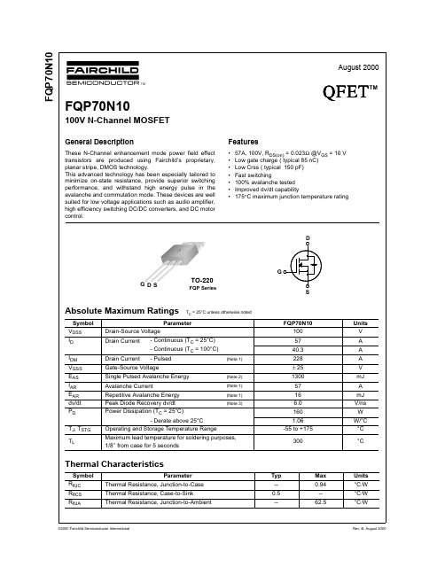
101
VDS, Drain-Source Voltage [V]
Figure 5. Capacitance Characteristics
VGS, Gate-Source Voltage [V]
IDR , Reverse Drain Current [A]
ID , Drain Current [A]
VDS = VGS, ID = 250 µA
2.0 --
4.0
V
VGS = 10 V, ID = 28.5 A
-- 0.019 0.023 Ω
VDS = 40 V, ID = 28.5 A (Note 4) --
45
--
S
Dynamic Characteristics
Ciss
Input Capacitance
G DS
TO-220
FQP Series
Absolute Maximum Ratings TC = 25°C unless otherwise noted
Symbol VDSS ID
IDM VGSS EAS IAR EAR dv/dt PD
TJ, TSTG
TL
Parameter
Drain-Source Voltage
--
--
1.5
V
trr
Reverse Recovery Time
Qrr
Reverse Recovery Charge
VGS = 0 V, IS = 70 A,
-- 110
--
ns
dIF / dt = 100 A/µs
(Note 4)
--
430
--
nC
Notes:
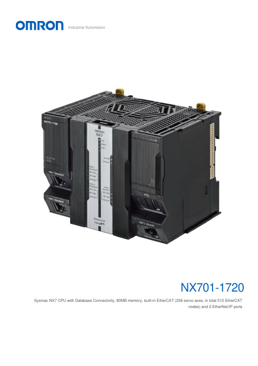
OMRON NX701-1720系统自动化控制器说明书
NX701-1720Sysmac NX7 CPU with Database Connectivity, 80MB memory, built-in EtherCAT (256 servo axes, in total 512 EtherCATnodes) and 2 EtherNet/IP portsIndustrial AutomationController functionality DB connection, Motion control, OPC-UA, Sequence control Primary task cycle time0.125 msProgram memory80 MBVariables memory260 MBMax. number of synchronous axes256Max. number of axes (incl. virtual)256Communication port(s)EtherCAT Master, EtherNet/IP, Ethernet TCP/IP Communication option(s)NoneMax. number of remote I/O nodes512I/O system NX I/O BusMax. number of expansion units0Product Height (unpacked)100 mmProduct Width (unpacked)132 mmProduct Depth (unpacked)100 mmProduct Weight (unpacked)880 gGX-JC033-port EtherCAT Junction module, 24 VDC power supplyGX-JC066-port EtherCAT Junction module, 24 VDC power supplyGX-JC06-H6-port EtherCAT Junction module, 24 VDC power supply, with node switchesHMC-SD492 4 GB SD memory cardNX-PA9001Sysmac NX power supply unit, 100 to 240 VAC, 90 W, "RUN" output relayNX-PD7001Sysmac NX power supply unit, 24 VDC, 70 W, "RUN" output relayW4S1-05D 5-port enhanced Ethernet switchCJ1W-BAT01Battery for CJ1M PLCsNX-END01Replacement end cover for NX I/O seriesAI Machine Automation Controller BrochureEN PDF 5.18 MBData validity check BrochureEN PDF 202 KBFDK CR14250SE Battery Safety DatasheetEN PDF 147 KBHigh-speed inspection BrochureEN PDF 319 KBMachine Safety Solution BrochureEN PDF 2.86 MBNJ-series -[EtherCAT]-ORIENTAL MOTOR aSTEP DC Multi-Axis Drive (AZDxA-KED)Connection GuideENPDF 3.99 MBNJ/NX Series BrochureEN PDF 4.18 MBNJ/NX-Series CPU Unit Motion Control Users ManualEN PDF 19.8 MBNJ/NX-Series CPU Unit Software Users ManualENPDF 24.2 MBNJ/NX-Series Database Connection CPU Units Users ManualENPDF 5.16 MBNJ/NX-Series Instructions Reference ManualEN PDF 11.6 MBNJ/NX-Series Motion Control Instructions Reference ManualENPDF 7.13 MBNJ/NX-Series OPC UA CPU Units Users ManualENPDF 3.82 MBNJ/NX-series -[EtherCAT]- CKD ABSODEX driver (AX9000TS/TH-U5)Connection GuideEN PDF 1.73 MBNJ/NX-series -[EtherCAT]- Hitachi ADV-Series AC Servo DrivesConnection GuideEN ZIP 4.29 MBNJ/NX-series -[EtherCAT]- Inficon gauge (BPG402-SE)Connection GuideEN PDF 1.22 MBNJ/NX-series -[EtherCAT]- Kashiyama Dry Vacuum Pump (E-CAT01 1ch)Connection GuideEN PDF 1.59 MBNJ/NX-series -[EtherCAT]- NX-ECC +NX-ILM400 -[IO-Link]-CKD Sensor (PPX series)Connection GuideEN PDF 2.43 MBNJ/NX-series -[EtherCAT]- NX-ECC +NX-ILM400 -[IO-Link]-CKD Sensor (WFC series)Connection GuideEN PDF 2.75 MBNJ/NX-series -[EtherCAT]- NX-ECC +NX-ILM400 -[IO-Link]-CKD WFK2 Flow sensorConnection GuideEN PDF 2.09 MBNJ/NX-series -[EtherCAT]- NX-ECC +NX-ILM400 -[IO-Link]-MTS Sensors (E-Series)Connection GuideEN PDF 2.4 MBNJ/NX-series -[EtherCAT]- NX-ECC + NX-ILM400 -[IO-Link]-PATLITE Beacon (NE-IL)Connection GuideENPDF 2.02 MB NJ/NX-series -[EtherCAT]- NX-ECC +NX-ILM400 -[IO-Link]-PATLITE Tower (LR6-IL)Connection GuideENPDF 2.08 MBNJ/NX-series -[EtherCAT]- NX-ECC +NX-ILM400 -[IO-Link]-SMC (ISA3-xxx)Connection GuideENPDF 2.61 MBNJ/NX-series -[EtherCAT]- NX-ECC +NX-ILM400 -[IO-Link]-SMC (xSE20Bx-L(-M/-P)-x)Connection GuideEN PDF 2.13 MBNJ/NX-series -[EtherCAT]- NX-ECC +NX-ILM400 -[IO-Link]-SMC ITVx000/-IO*Connection GuideEN PDF 1.89 MBNJ/NX-series -[EtherCAT]- NX-ECC +NX-ILM400 -[IO-Link]-SMC Servo 24VDC(JXCL1)Connection GuideEN PDF 2.23 MBNJ/NX-series -[EtherCAT]- NX-ECC +NX-ILM400 -[IO-Link]-Schmalz Ejector (SCPSi)Connection GuideEN PDF 2.4 MBNJ/NX-series -[EtherCAT]- NX-ECC +NX-ILM400 -[IO-Link]-ifm (O5D10x/O5D15x)Connection GuideEN PDF 2.42 MBNJ/NX-series -[EtherCAT]- NX-ECC +NX-ILM400 -[IO-Link]-ifm (PN7x94)Connection GuideEN PDF 2.72 MBNJ/NX-series -[EtherCAT]- NX-ECC +NX-ILM400 -[IO-Link]-ifm (TN24xx)Connection GuideEN PDF 2.74 MBNJ/NX-series -[EtherCAT]- NX-ECC +NX-ILM400 -[IO-Link]-ifm TR7439 Pt100/1000Connection GuideEN PDF 2.43 MBNJ/NX-series -[EtherCAT]- NidecSankyo S-FLAG II SeriesAC Servo (DB6xx41)Connection GuideEN PDF 2.65 MBNJ/NX-series -[EtherCAT]- ORIENTALMOTOR Stepper Motor(AZ-series)Connection GuideEN PDF 2.89 MBNJ/NX-series -[EtherCAT]- SANYODENKI AC ServoSANMOTION R 3EMODEL TYPE SConnection GuideEN PDF 3.08 MBNJ/NX-series -[EtherCAT]- SANYODENKI AC ServoSANMOTION RADVANCED MODELTYPE FConnection GuideEN PDF 3.61 MBNJ/NX-series -[EtherCAT]- SHIMADZUPower Unit for TurboMolecular Pump (TMP)Connection GuideEN PDF 1.29 MBNJ/NX-series -[EtherCAT]- SICKAbsolute Encoder(AFS60/AFM60)Connection GuideEN PDF 1.52 MBNJ/NX-series -[EtherCAT]- SchmalzCompact Terminal(SCTSi-ECT)Connection GuideEN PDF 1.33 MBNJ/NX-series -[EtherCAT]- WeidmüllerRemote I/O System (u-remote IP20)Connection GuideEN PDF 1.8 MBNJ/NX-series -[EtherCAT]- YASKAWAΣ-7-seriesConnection GuideEN ZIP 3.77 MBNJ/NX-series -[EtherNet/IP]- Balluff BNIEIP-50x-105-Z015Connection GuideEN PDF 3.35 MBNJ/NX-series -[EtherNet/IP]- CKDABSODEX Driver(AX9000TS/TH-U6)Connection GuideEN PDF 1.71 MBNJ/NX-series -[EtherNet/IP]- HMSAnybus CommunicatorConnection GuideEN PDF 1.51 MBNJ/NX-series -[EtherNet/IP]- HilschernetTAP NT100 Gateway(NT 100-RE-DN)Connection GuideEN PDF 3.5 MBNJ/NX-series -[EtherNet/IP]- IAI RCON system & MCON / MSCON / MSEP ControllerConnection GuideEN PDF 1.9 MB NJ/NX-series -[EtherNet/IP]- KOGANEIManifold Solenoid Valve(F Series)Connection GuideEN PDF 2.43 MBNJ/NX-series -[EtherNet/IP]- NordsonProBlue AdhesiveMeltersConnection GuideEN PDF 2.61 MBNJ/NX-series -[EtherNet/IP]- ORIENTALMOTOR αSTEPCompatible Driver (AZD-xEP)Connection GuideEN PDF 1.82 MBNJ/NX-series -[EtherNet/IP]- SMCSolenoid Valve (SI UnitEX260-SEN#)Connection GuideEN PDF 1.65 MBNJ/NX-series -[EtherNet/IP]- SchmalzK.K. Compact Terminal(SCTSi-EIP)Connection GuideEN PDF 1.69 MBNJ/NX-series -[EtherNet/IP]- ifm IO-Link master (AL1322)Connection GuideEN PDF 3.18 MBNJ/NX-series -[EtherNet/IP]- ifm IO-Link master (AL1920)Connection GuideEN PDF 3.07 MBNJ/NX-series MachineAutomation ControllerBrochureEN PDF 1.81 MBNJ/NX-series MachineAutomation ControllerDatabase ConnectionCPU UnitBrochureEN PDF 1.37 MBNJ/NX/NY-seriesSysmac Library User’sManual for SafetySystem Monitor LibraryUsers ManualEN PDF 922 KBNX-series -[EthernetTCP/IP]- V330-F, V430-FCode ReadersConnection GuideENPDF 2.89 MBNX-series -[RS-232C]-V320-F, V420-F, V430-FCode ReadersConnection GuideENPDF 2.48 MBNX7 MachineAutomation ControllerDatasheetENPDF 2.43 MBQuality gate for eachprocessBrochureENPDF 167 KBSysmacCatalogueEN PDF 43.5 MBSysmac: A FullyIntegrated PlatformBrochureENPDF 10.2 MB。
TLP701中文资料
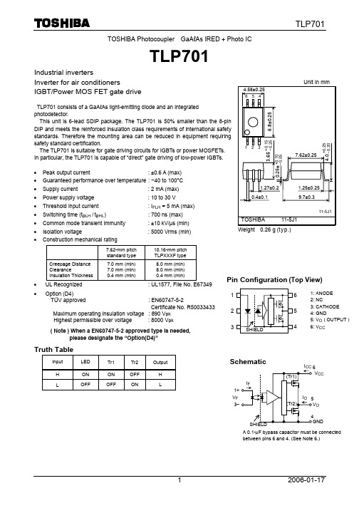
This unit is 6-lead SDIP package. The TLP701 is 50% smaller than the 8-pin DIP and meets the reinforced insulation class requirements of international safety standards. Therefore the mounting area can be reduced in equipment requiring safety standard certification.
4
6: VCC
Schematic
IF 1+ VF 3−
(Tr1)
ICC 6 VCC
IO 5
(Tr2)
VO
SHIELD
4 GND
A 0.1-µF bypass capacitor must be connected
between pins 6 and 4. (See Note 6.)
1
2006-01-17
( Note ) When a EN60747-5-2 approved type is needed, please designate the “Option(D4)”
Truth Table
Input
LED
Tr1
Tr2
Output
H
ON
ON
OFF
H
L
OFF
OFF
ON
L
1.27±0.2 0.4±0.1
L-NP10中文资料
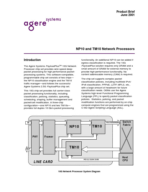
— Modifying data anywhere in the packet
— Configurations include OC192c, 4xOC48c, 1G/10G Ethernet, 192xDS3, etc.
s PCI 2.2 compliant 66-MHz, 32-/64-bit host interface to allow easy interfacing to a variety of host microprocessors and other support logic
s Programmable per-flow statistics and policing allows OEMs to implement highly differentiated admission control and billing policies.
s Full carrier-class traffic management functionality to help maximize the amount of premium traffic that can be reliably served, with support for: — Hierarchical weighted fair queuing (WFQ) with bandwidth and delay guarantees
元器件交易网
Product Brief June 2001
tlp5701的参数
tlp5701的参数全文共四篇示例,供读者参考第一篇示例:TLP5701是一款高性能、低功耗、双路数字隔离器,广泛应用于工业自动化、通信和电源系统中。
它具有出色的抗干扰能力,可以有效地隔离信号和电源,保护系统免受外部干扰和电气噪声的影响。
1. 隔离电压:TLP5701具有高达3750Vrms的隔离电压,可以在输入和输出之间提供充分的电气隔离,有效地防止信号的串扰和电气冲击。
2. 传输速率:TLP5701支持高达25Mbps的传输速率,能够实现快速而稳定的数据传输,满足工业自动化和通信系统对高速通信的需求。
3. 工作温度范围:TLP5701的工作温度范围为-40℃至125℃,具有良好的耐高低温性能,适用于各种恶劣环境下的工作条件。
4. 输入电压:TLP5701的输入电压范围为3.3V至5V,可与多种类型的微控制器和数字电路进行兼容,方便集成到各种系统中。
5. 包装形式:TLP5701采用小型SOP-8封装,具有较小的占地面积和轻便的重量,便于安装和布线。
6. 安全认证:TLP5701通过UL、CSA、VDE等多项安全认证,确保产品符合国际标准,具有可靠的品质和性能。
TLP5701是一款性能优秀、功能齐全的数字隔离器,具有高隔离电压、快速传输速率、广泛的工作温度范围等优点,适用于各种工业自动化、通信和电源系统中,是您最佳的选择。
第二篇示例:TLP5701是一款高性能、多功能的电流检测器,适用于工业自动化、电力电子和通信设备等领域。
下面将介绍TLP5701的主要参数和特点,帮助用户更好地了解和使用这款产品。
1. 输入电流范围:TLP5701可检测的输入电流范围为0至20mA 或0至50mA,用户可以根据实际需求选择合适的范围。
2. 输出类型:TLP5701采用双通道输出设计,支持模拟输出和数字输出两种形式。
模拟输出为4至20mA电流信号,数字输出为RS485接口。
3. 精度和稳定性:TLP5701具有高精度和稳定性,可实现高精度的电流检测和监测。
UPD70320L资料

8
7
6
5
4
3
2
1 84 83 82 81 80 79 78 77 76 75 74 73 72 71 70 69 68 67 66 65 64 63 62 61 60 59 58 57 56 55 54 PT7 PT6 PT5 PT4 PT3 PT2 PT1 PT0 P17/READY P16/SCK0 P15/TOUT P14/INT/POLL P13/INTP2/INTAK P12/INTP1 P11/INTP0 P10/NMI P27/HLDRQ P26/HLDAK P25/TC1 P24/DMAAK1 P23/DMARQ1
PROGRAMMABLE INTERRUPT CONTROLLER
INSTRUCTION DECODER MICRO SEQUENSER MICRO ROM
QUEUE (6 byte) EA D0 to D7
16-BIT TIMER
TIME BASE COUNTER
PORT
PORT with COMPARATOR
µPD70320L µPD70320L-8
REFRQ
RESET
IOSTB
MREQ
MSTB
GND
R/W
P06
P05
P04
P03
P02
P01
P00
VDD
VTH
EA
X2
X1
IC
11 10 9 P07/CLKOUT D0 D1 D2 D3 D4 D5 D6 D7 A0 A1 A2 A3 A4 A5 A6 A7 A8 A9 A10 A11 12 13 14 15 16 17 18 19 20 21 22 23 24 25 26 27 28 29 30 31 32
SmartLine STG700 STG70L 压力传感器技术说明书
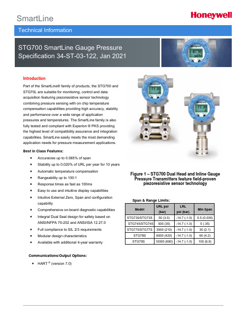
SmartLineTechnical InformationSTG700 SmartLine Gauge Pressure Specification 34-ST-03-122, Jan 2021IntroductionPart of the SmartLine® family of products, the STG700 andSTG70L are suitable for monitoring, control and dataacquisition featuring piezoresistive sensor technologycombining pressure sensing with on chip temperaturecompensation capabilities providing high accuracy, stabilityand performance over a wide range of applicationpressures and temperatures. The SmartLine family is alsofully tested and compliant with Experion ® PKS providingthe highest level of compatibility assurance and integrationcapabilities. SmartLine easily meets the most demandingapplication needs for pressure measurement applications.Best in Class Features:∙Accuracies up to 0.065% of span∙Stability up to 0.020% of URL per year for 10 years∙Automatic temperature compensation∙Rangeability up to 100:1∙Response times as fast as 100ms∙Easy to use and intuitive display capabilities∙Intuitive External Zero, Span and configuration capability∙Comprehensive on-board diagnostic capabilities∙Integral Dual Seal design for safety based on ANSI/NFPA 70-202 and ANSI/ISA 12.27.0∙Full compliance to SIL 2/3 requirements∙Modular design characteristics∙Available with additional 4-year warrantyCommunications/Output Options:∙HART ® (version 7.0)Figure 1 – STG700 Dual Head and Inline Gauge Pressure Transmitters feature field-proven piezoresistive sensor technology Span & Range Limits:ModelURL psi(bar)LRLpsi (bar)Min Span STG735/STG73S 50 (3.5) -14.7 (-1.0) 0.5 (0.035) STG745/STG74S 500 (35) -14.7 (-1.0) 5 (.35)STG775/STG77S 3000 (210) -14.7 (-1.0) 30 (2.1) STG78S 6000 (420) -14.7 (-1.0) 60 (4.2)STG79S 10000 (690) -14.7 (-1.0) 100 (6.9)2 STG700 Smart Pressure TransmitterDescriptionThe SmartLine family pressure transmitters are designed around a high performance piezo-resistive sensor. This one sensor integrates multiple sensors linking process pressure measurement with on-board static pressure (GP Models) and temperature compensation measurements.Indication/Display OptionStandard LCD Display Featureso Modular (may be added or removed in the field)o Supports HART protocol varianto0, 90,180, & 270 degree position adjustmentso Configurable (HART only) and standard (Pa, KPa, MPa, KGcm2, Torr, ATM, inH2O, mH2O, bar, mbar,inHG, FTH2O, mmH2O, mm HG, & psi) measurementunits.o 2 Lines 6 digits PV (9.95H x 4.20W mm) 8 Characters o Square root output indication (√)o Write protect Indicationo Built in Basic Device Configuration through Internal or External Buttons – Range/Engineering Unit/Loop Test /Loop Calibration/Zero /Span Settingo Multiple language capability (EN, RU)DiagnosticsSmartLine transmitters all offer digitally accessible diagnostics which aid in providing advanced warning of possible failure events minimizing unplanned shutdowns, providing lower overall operational costsSystem Integrationo SmartLine communications protocols all meet the most current published standards for HART.o All ST 700 units are Experion tested to provide thehighest level of compatibility assurance Configuration ToolsExternal Two Button Configuration OptionSuitable for all electrical and environmental requirements, SmartLine offers the ability to configure the transmitter and display, for all basic parameters, via two externally accessible buttons when a display option isselected. Zero/span capabilities are also optionally available via two external buttons with or without selection of the display option.Internal Two Button Configuration OptionThe Standard display has two buttons that can be used for Basic configuration such as re ranging, PV Engineering unit setting, Zero/Span settings, Loop testing and calibration functions.Hand Held ConfigurationSmartLine transmitters feature two-way communication and configuration capability between the operator and the transmitter. All Honeywell transmitters are designed and tested for compliance with the offered communication protocols and are designed to operate with any Standards compliant handheld configuration device.Personal Computer ConfigurationField Device Manager (FDM) Software and FDM Express are also available for managing HART device configurations.Modular DesignTo help contain maintenance & inventory costs, all ST 700 transmitters are modular in design supporting the user’s ability to replace meter bodies, standard displays or electronic modules without affecting overall performance. Each meter body is uniquely characterized to provide in-tolerance performance over a wide range of application variations in temperature and pressure.Modular Features∙Meter body replacement∙Add or remove standard displays∙Add or remove lightning protection (terminalconnection)With no performance effects, Honeywell’s unique modularity results in lower inventory needs and lower overall operating costs.STG700 Smart Pressure Transmitter3Performance SpecificationsReference Accuracy: (conformance to +/-3 Sigma)Table 1ModelURLLRLMin SpanMaximum Turndown Ratio Stability (% URL/Year for 10 years)Reference Accuracy 1,2 (% Span) StandardS t a n d a r d A c c u r a c ySTG73550 psi (3.5 bar) -14.7 psi (-1.0 bar) 0.5 psi (.035 bar) 100:1 0.020 0.065STG73S 50 psi (3.5 bar) -14.7 psi (-1.0 bar) 0.5 psi (.035 bar) STG745 500 psi (35 bar) -14.7 psi (-1.0 bar) 5 psi (.35 bar) STG74S 500 psi (35 bar) -14.7 psi (-1.0 bar) 5 psi (.35 bar) STG775 3000 psi (210 bar) -14.7 psi (-1.0 bar) 30 psi (2.1 bar) STG77S 3000 psi (210 bar) -14.7 psi (-1.0 bar) 30 psi (2.1 bar) STG78S 6000 psi (420 bar) -14.7 psi (-1.0 bar) 60 psi (4.2 bar) STG79S10000 psi (690 bar)-14.7 psi (-1.0 bar)100 (6.9 bar)Zero and span may be set anywhere within the listed (URL/LRL) range limitsAccuracy, Span and Temperature Effect: (Conformance to +/-3 Sigma)Table 2Accuracy 1,2 (% of Span)Combined Zero & Span temperature Effect (% Span / 28o C(50o F))Model URLReferenceTurndown ABC(see URL units)D E S t a n d a r d A c c u r a c ySTG73550 psi (3.5 bar) 16.7:1 0.005 0.0603 (0.21) 0.070 0.008 STG73S 50 psi (3.5 bar) 8:1 6 (0.42) 0.100 0.015 STG745 500 psi (35 bar) 20:1 25 (1.75) 0.075 0.013 STG74S 500 psi (35 bar) 20:1 25 (1.75) 0.100 0.020 STG775 3000 psi (210 bar) 8.5:1 350 (24.5) 0.075 0.013 STG77S 3000 psi (210 bar) 8.5:1 350 (24.5) 0.100 0.025 STG78S 6000 psi (420 bar) 10:1 600 (42) 0.100 0.070 STG79S10000 psi (690 bar) 8:10.025 0.040 1250 (86.25)0.2000.170Turn Down EffectTemp EffectTotal Performance (% of Span):Total Performance Calculation : = +/- √ (Accuracy)2 + (Temperature Effect)2Total Performance Examples (for comparison): (standard accuracy, 5:1 Turndown, +/-50 o F (28o C) shift) STG735 @ 10 psi: 0.128% of span STG73S @ 10 psi: 0.187% of spanSTG745 @ 100 psi: 0.154% of span STG74S @ 100 psi: 0.210% of spanSTG775 @ 600 psi: 0.154 % of span STG77S @ 600 psi: 0.234% of span STG78S @ 1200 psi: 0.455% of span STG79S @ 2000 psi: 1.052% of spanTypical Calibration Frequency:Calibration verification is recommended every two (2) yearsNotes:1. Terminal Based Accuracy - Includes combined effects of linearity, hysteresis, and repeatability. Analog output adds 0 .006% of span.2. For zero based spans and reference conditions of: 25 o C (77 o F) for LRV > = 0 psia, 10 to 55% RH, and 316 Stainless Steel barrierdiaphragm.4 STG700 Smart Pressure Transmitter Operating Conditions – All ModelsParameter ReferenceConditionRated Condition Operative Limits Transportation andStorage︒C ︒F ︒C ︒F ︒C ︒F ︒C ︒FAmbient Temperature125±1 77±2 -40 to 85 -40 to 185 -40 to 85 -40 to 185 -55 to 120 -67 to 248 Meter Body Temperature 25±1 77±2 -40 to 110 -40 to 230 -40 to 125 -40 to 257 -55 to 120 -67 to 248 Humidity %RH10 to 55 0 to 100 0 to 100 0 to 100 Vac. Region – Min. PressuremmHg absoluteinH2O absoluteAtmosphericAtmospheric25132 (short term ) 21 (short term ) 2Supply Voltage Load Resistance 10.8 to 42.4 Vdc at terminals0 to 1,440 ohms (as shown in Figure 2)Maximum AllowableWorking Pressure (MAWP)3, 4(ST700 products are rated to Maximum Allowable Working Pressure. MAWP depends on Approval Agency andtransmitter materials ofconstruction.)STG735: 50 psi (3.5 bar) STG73S: 50 psi (3.5 bar ) STG745: 500 psi (35 bar) STG74S: 500 psi (35 bar ) STG775: 3000 psi (210 bar ) STG77S: 3000 psi (210 bar ) STG78S: 6000 psi (420 bar ) STG79S: 10000 psi (690 bar )LCD Display operating temperature -20︒C to +70︒C Storage temperature -30︒C to 80︒C.2 Short term equals 2 hours at 70︒C (158︒F).3 Units can withstand overpressure of 1.5 x MAWP without damage.4Consult the factory for MAWP of ST 700 transmitters with CRN approval.5 Silicone minimum temperature rating is -40︒C (-40︒F). CTFE minimum temperature rating is -30︒C (-22︒F).Figure 2 - Supply voltage and loop resistance chart & calculationsSTG700 Smart Pressure Transmitter 52 Hastelloy® C-276 or UNS N102764 Supplied as 316 SS or as Grade CF8M, the casting equivalent of 316 SS.5 Carbon Steel heads are zinc-plated and not recommended for water service due to hydrogen migration. For that service, use 316stainless steel wetted Process Heads.6 Hastelloy® C-276 or UNS N10276. Supplied as indicated or as Grade CW12MW, the casting equivalent of Hastelloy® C-2766 STG700 Smart Pressure Transmitter Communications Protocols & DiagnosticsHART ProtocolVersion:HART 7Power SupplyVoltage: 10.8 to 42.4Vdc at terminalsLoad: Maximum 1440 ohms See Figure 2.Minimum Load: 0 ohms. (For handheld communications aminimum load of 250 ohms is required)Standard DiagnosticsST 700 top level diagnostics are reported as either criticalor non-critical and readable via the DD/DTM tools orintegral display as shown.Non-Critical DiagnosticsRefer to ST 700 manuals for additional level diagnosticinformation.STG700 Smart Pressure Transmitter 78 STG700 Smart Pressure TransmitterSTG700 Smart Pressure Transmitter 910 STG700 Smart Pressure TransmitterSTG700 Smart Pressure Transmitter 11 Notes:1.Operating Parameters:Voltage= 11 to 42 V DC Current= 4-20 mA Normal2.Intrinsically Safe Entity Parametersa. Analog/ DE/ HART Entity Values:Vmax= Ui = 30V Imax= Ii= 105mA Ci = 4.2nF Li =984 uH Pi =0.9WTransmitter with Terminal Block Revision E or LaterVmax= Ui = 30V Imax= Ii= 225mA Ci = 4.2nF Li = 0 Pi =0.9WNote : Transmitter with Terminal Block Revision E or laterThe revision is on the label that is on the module. There will be two lines of text on the label:∙First is the Module Part #: 50049839-001 or 50049839-002∙Second line has the supplier information, along with the REVISION:XXXXXXX-EXXXX, THE “X” is production related, THE POSITION of the “E” IS THE REVISION.Other Certification OptionsMaterialso NACE MRO175, MRO103, ISO1515612 STG700 Smart Pressure Transmitter Mounting & Dimensional DrawingsReference Dimensions:millimetersinchesMounting Configurations: (Dual head design)Dimensions: (Dual head design)Figure 3 – Typical mounting dimensions of STG735, STG745 & STG775 for reference R efer to the User’s manual (34-ST-25-44) for full details on mounting and installation.STG700 Smart Pressure Transmitter 13Reference Dimensions:millimetersinchesMounting Configurations (Inline Designs)Dimension (Inline Design)Figure 4 – Typical mounting dimensions of STG74S, STG77S, STG78S, & STG79S for reference R efer to the User’s manual (34-ST-25-44) for full details on mounting and installation.14 STG700 Smart Pressure TransmitterModel STG700Gauge Pressure TransmittersModel Selection Guide1a STG735,745,775 supplied via 1/2" flange adapter same material as process head except carbon steel shall use 316 SS 1bReference head available w ith Dual Head Gage models only. In-Line Gage models are supplied w ith Process Head only.Except Carbon Steel Heads shall use 316SS Vent/Drain & Plugs and or 1/2" adaptersModel Selection GuideModel Selection Guides are subject to change and are inserted into the specifications as guidance only.STG700 Smart Pressure Transmitter 15REVERSED 90°/STANDARD SELECTION 2 SELECTION 3STG79SSTG77S, STG78SSTG73S,STG74SSTG775STG735,STG745HH HTABLE IIMeter Body & Connection OrientationStandardHigh Side Left, Ref Side Right 2 / Std Head Orientation1*****ReversedRef Side Left, High Side Right22**90/StandardHigh Side Left, Ref Side Right 2 / 900 Head Rotation 3h hTABLE III 0*****A*****B****p C *****D *****E *****F *****G *****I *****J *****K*****TABLE IV ConnectionLightning Protection1/2 NPT None A _ _*****M20None B _ _*****1/2 NPT Yes C _ _*****M20Yes D _ _*****1/2 NPT None E _ _*****M20None F _ _*****1/2 NPT Yes G _ _*****M20YesH _ _*****_ H _*****IndicatorLanguagesNone None _ _ 0*****NoneNone _ _ A *****Standard(w/Internal Zero,Span&Configbuttons)EN, RU_ _ S*****Standard(w/Internal Zero,Span&Configbuttons)EN, RU_ _ T*****TABLE V1 _ _*****Write ProtectFail Mode Disabled High> 21.0mAdc Honeywell Std (3.8 - 20.8 mAdc)_ 1 _*****Disabled Low< 3.6mAdc Honeywell Std (3.8 - 20.8 mAdc)_ 2 _*****EnabledHigh> 21.0mAdc Honeywell Std (3.8 - 20.8 mAdc)_ 3 _*****Enabled Low< 3.6mAdc Honeywell Std (3.8 - 20.8 mAdc)_ 4 _*****Factory Standard_ _ S *****Custom Configuration (Unit Data Required from customer)_ _ C*****2 Left side/Right side as view ed from the customer connection perspective3 NAMUR Output Limits are configurable by customer 4P rocess connections w ill vary on In-Line ModelsSELECTION 14STANDARD Head/ConnectOrientationAGENCY APPROVALSNo Approvals RequiredApprovalsCCoE Explosion proof, Intrinsically Safe & Non-incendive UATR Flameproof, Intrinsically Safe & DustproofIECEx Explosion proof, Intrinsically Safe & Non-incendive <FM> Explosion proof, Intrinsically Safe, Non-incendive, & Dustproof CSA Explosion proof, Intrinsically Safe, Non-incendive, & Dustproof ATEX Explosion proof, Intrinsically Safe & Non-incendive SAEx Explosion proof, Intrinsically Safe & Non-incendive INMETRO Explosion proof, Intrinsically Safe & Non-incendive NEPSI Explosion proof, Intrinsically Safe & Non-incendiveEAC-Customs Union(Russia,Belarus and Kazakhstan)EX Approval Flameproof,Intrinsically Safe TRANSMITTER ELECTRONICS SELECTIONSa. Electronic Housing Material & Connection TypeMaterialPolyester Powder Coated Aluminum Polyester Powder Coated Aluminum Polyester Powder Coated Aluminum Polyester Powder Coated Aluminum 316 Stainless Steel (Grade CF8M)316 Stainless Steel (Grade CF8M)316 Stainless Steel (Grade CF8M)316 Stainless Steel (Grade CF8M)b. Output/ ProtocolAnalog OutputDigital Protocol4-20mA dcHART Protocolc. Customer Interface SelectionsE xt Zero,Span & Config ButtonsNoneYes (Zero/Span Only)NoneYesCONFIGURATION SELECTIONSa. Application Software DiagnosticsStandard Diagnosticsb. Output Limit, Failsafe & Write Protect Settings High & Low Output Limits3General Configurationc. General Configuration16 STG700 Smart Pressure Transmitter⁵The PM option is available on all Smartline Pressure Transmitter process wetted parts such as process heads, flanges, bushings and ventplugs except plated carbon steel process heads and flanges. PM option information is also available on diaphragms except STG and STA in-line construction pressure transmitters.For more informationTo learn more about SmartLine Transmitters, visit Or contact your Honeywell Account ManagerProcess Solutions Honeywell1250 W Sam Houston Pkwy S Houston, TX 77042Honeywell Control Systems LtdHoneywell House, Skimped Hill Lane Bracknell, England, RG12 1EB34-ST-03-122 Jan 20212021 Honeywell International Inc.Shanghai City Centre, 100 Jungi Road Shanghai, China 20061Sales and ServiceFor application assistance, current specifications, ordering, pricing, and name of the nearest Authorized Distributor, contact one of the offices below.ASIA PACIFICHoneywell Process Solutions, Phone: + 800 12026455 or +44 (0) 1202645583 (TAC) hfs-tac-*********************AustraliaHoneywell LimitedPhone: +(61) 7-3846 1255 FAX: +(61) 7-3840 6481 Toll Free 1300-36-39-36 Toll Free Fax: 1300-36-04-70China – PRC - Shanghai Honeywell China Inc.Phone: (86-21) 5257-4568 Fax: (86-21) 6237-2826SingaporeHoneywell Pte Ltd.Phone: +(65) 6580 3278 Fax: +(65) 6445-3033South KoreaHoneywell Korea Co Ltd Phone: +(822) 799 6114 Fax: +(822) 792 9015EMEAHoneywell Process Solutions, Phone: + 800 12026455 or +44 (0) 1202645583Email: (Sales)*************************** or (TAC)*****************************WebKnowledge Base search engine http://bit.ly/2N5VldiAMERICASHoneywell Process Solutions, Phone: (TAC) (800) 423-9883 or (215) 641-3610(Sales) 1-800-343-0228Email: (Sales)*************************** or (TAC)*****************************WebKnowledge Base search engine http://bit.ly/2N5VldiSpecifications are subject to change without notice.。
IXYS CORPORATION IXYH24N170CV1 数据手册说明书

CES I C110= 24A V CE(sat) ≤ 4.0V t fi(typ)= 78nsG = Gate C = Collector E = Emitter Tab = CollectorTO-247 ADSymbol Test Conditions Characteristic Values (T J = 25︒C, Unless Otherwise Specified) Min. Typ. Max.BV CES I C = 250μA, V GE = 0V 1700 VV GE(th)I C= 250μA, V CE = V GE3.05.0VI CES V CE = V CES , V GE = 0V25μA T J = 150︒C 5 mA I GES V CE = 0V, V GE = ±20V±100 nAV CE(sat)I C = 24A, V GE = 15V, Note 13.54.0 V T J = 150︒C5.0 VSymbol Test ConditionsMaximum Ratings V CES T J = 25°C to 175°C1700V V CGR T J = 25°C to 175°C, R GE = 1M Ω 1700V V GES Continuous ±20V V GEMTransient±30VI C25 T C = 110°C 58 A I C110T C = 110°C 24 A I F110T C = 110°C 28 A I CM T C = 25°C, 1ms 140 A SSOA V GE = 15V, T VJ = 150°C, R G = 5ΩI CM = 96A (RBSOA) Clamped Inductive Load 1360 V P C T C = 25°C500W T J -55 ... +175°C T JM 175°C T stg -55 ... +175°CT LMaximum Lead Temperature for Soldering 300°CT SOLD 1.6 mm (0.062in.) from Case for 10s 260 °C M d Mounting Torque 1.13/10Nm/lb.in.Weight6gHigh Voltage XPT TM IGBT w/ DiodeFeatures●High Voltage Package ●High Blocking Voltage ●Low Saturation VoltageAdvantages●Low Gate Drive Requirement ●High Power DensityApplications●Switch-Mode and Resonant-Mode Power Supplies●Uninterruptible Power Supplies (UPS)●Laser Generators●Capacitor Discharge Circuits ●AC SwitchesIXYS Reserves the Right to Change Limits, Test Conditions, and Dimensions.Notes:1. Pulse test, t ≤ 300μs, duty cycle, d ≤ 2%.2. Switching times & energy losses may increase for higher V CE (clamp), T J or R G .Reverse Diode (FRED)(T= 25°C, Unless Otherwise Specified) Characteristic ValueSymbol Test Conditions (T J = 25°C Unless Otherwise Specified)fs I C = 24A, V CE = 10V, Note 1 12 20GiGate Input ResistanceC ie sC oes V CE = 25V, V GE C resQ g(on)Q ge I C = 24A, V GE = 15V, V Q gc 1 - Gate2,4 - Collector 3 - EmitterTO-247 (IXYH) Outline3D SA LDREE1L1D1D2A2Q CB A0P 0K M D B Mb40P1124b c eIXYS OPTIONR1 J M C A Mb2A1PRELIMINARY TECHNICAL INFORMATIONThe product presented herein is under development. The Technical Specifications offered are derived from a subjective evaluation of the design, based upon prior knowledge and experi-ence, and constitute a "considered reflection" of the anticipated result. IXYS reserves the right to change limits, test conditions, and dimensions without notice.Fig. 1. Output Characteristics @ T 1624324048I C - A m p e r e sIXYS Reserves the Right to Change Limits, Test Conditions, and Dimensions.Fig. 7. Transconductance912151821242730g f s - S i e m e n sFig. 12. Inductive Switching Energy Loss vs.Gate Resistance46810E o f f - M i l l i J o u l e sE off E onT J = 150oC , V GE = 15V V CE = 850VIXYS Reserves the Right to Change Limits, Test Conditions, and Dimensions.Fig. 18. Inductive Turn-on Switching Times vs.Gate Resistance6080100120140t r i - N a n o s e c o n d st r i t d(on)T J = 150oC, V GE = 15V V CE = 850VFig. 21. Diode Forward Characteristics406080100I F (A )。
Dell OptiPlex 170L 使用者指南说明书
Dell™ OptiPlex™ 170L 使用者指南註、注意事項和警示縮寫和簡寫用語若要獲得縮寫和簡寫用語的完整清單,請參閱詞彙表。
如果您購買的是 Dell™ n Series 電腦,則本文件中關於 Microsoft ® Windows ® 作業系統的所有參考均不適用。
電腦的說明文件尋找有關您電腦的資訊 規格 清潔您的電腦進階功能LegacySelect 技術控制 管理功能 安全保護 密碼保護 系統設定程式 啟動至 USB 裝置 電源按鈕 電源管理 超執行緒小型桌上型電腦關於您的電腦前視圖 後視圖 主機內部 主機板元件連接與卸下電腦腳架新增和卸下零件開始之前 打開機箱蓋 電池 插卡 底架喇叭 磁碟機 I/O 面板 記憶體 電源供應器 處理器 主機板 裝回機箱蓋迷你直立型電腦關於您的電腦前視圖 後視圖 主機內部 主機板元件新增和卸下零件開始之前 卸下機箱蓋 電池 插卡 底架喇叭 控制面板 磁碟機 I/O 面板 記憶體 電源供應器 處理器 主機板 裝回機箱蓋電腦和軟體問題進階故障排除 解決問題 獲得幫助其他資訊Microsoft ® Windows ® XP 功能 詞彙表 保固註:「註」表示可以幫助您更有效地使用電腦的重要資訊。
注意事項:「注意事項」表示有可能會損壞硬體或導致資料遺失,並告訴您如何避免此類問題。
警示:「警示」表示可能會導致財產損失、人身受傷甚至死亡。
Drivers and Utilities CD (ResourceCD)、作業系統媒體以及《快速參考指南》都是可選的,它們可能並非隨附於所有電腦。
本文件中的資訊如有更改,恕不另行通知。
©2004D e l l I n c.。
版權所有,翻印必究。
未經 Dell Inc. 的書面許可,不得以任何形式進行複製。
本文中使用的商標:D e l l、D E L L徽標、O p t i P l e x、I n s p i r o n、D i m e n s i o n、L a t i t u d e、D e l l P r e c i s i o n、D e l l N e t、T r a v e l L i t e、P o w e r V a u l t、P o w e r A p p、A x i m和 Dell OpenManage是 Dell Inc. 的商標﹔I n t e l, P e n t i u m 和 C e l e r o n是 Intel Corporation 的註冊商標﹔M i c r o s o f t、M S-D O S和 W i n d o w s是 Microsoft Corporation 的註冊商標﹔IBM和 O S/2是 International Business Machines Corporation 的註冊商標﹔NetWare和 N o v e l l是 Novell, Inc. 的註冊商標。
OPB470L11;OPB470N11;OPB470P11;OPB470T11;OPB471L11;中文规格书,Datasheet资料

Description:The OPB460, OPB470, OPB480 and OPB490 series of Photologic® photo integrated circuit switches provide optimum flexibility for the design engineer. Building from a standard housing with a 0.125” (3.180 mm) wide slot, a user can specify the type and polarity of TTL output, discrete shell material, aperture width and choice of mounting configurations. OPB460 through OPB473 have 0.425” (10.795 mm) PCBoard leads with 0.320” (8.1 mm) spacing. OPB480 through OPB493 have 24” (609 mm) 26 AWG wires (UL approved wires).All devices in this series exhibit performance over supply voltages ranging from 4.5 V to 16.0 V, and may be specified as buffered or inverted with 10 kW Pull-up or Open Collector output. Devices are also TTI/LSTTL compatible and can drive up to 10 TTL loads.Custom electrical, wire and cabling and connectors are available. Contact your local representative or OPTEK for more information.OPTEK Assembly6 —7 —8 —9 —0 — Buffered 10 kΩ Output1 — Buffered Open-Collector Output2 — Inverted 10 kΩ Output3 — Inverted Open-Collector OutputAll PCBoard Versions RoHS Compliant:Z = Wire Version RoHS CompliantSensor Aperture:1 = 0.010” [0.25 mm]Emitter Aperture:1 = 0.010” [0.25 mm]Mounting Configurations:L — Emitter side mounting tab onlyN — No mounting tabsP — Sensor side mounting tab onlyT — Two mounting tabsPart Number Guide — OPB460, OPB470, OPB480, OPB490 Series Applications:• Mechanical switch replacement• Speed indication (tachometer)• Mechanical limit indication• Edge sensingDIMENSIONS ARE IN:CONTAINS POLYSULFONETo avoid stress cracking, we suggest using ND Industries’ Vibra-Tite for thread-locking. Vibra-Tite evaporates fast without causing structuralfailure in OPTEK’s molded plastics.Applies to: OPB460, OPB470, OPB480, OPB490.INCHES[ MILLIMETERS]Color-Pin Description Red -1 Anode Black-2 Cathode White-3 Vcc Blue -4 Output Green -5GroundNotes:(1) RMA flux is recommended. Duration can be extended to 10 seconds maximum when flow soldering.(2) Derate linearly 1.67 mW/°C above 25° C (OPB460, OPB470) or derate linearly 1.82 mW/°C above 25° C (OPB480, OPB490). (3) Derate linearly 1.50 mW/°C above 25° C (OPB460, OPB470) or derate linearly 1.64 mW/°C above 25° C(OPB480, OPB490). (4) Derate linearly 3.17 mW/°C above 25° C (OPB460, OPB470) or derate linearly 3.45 mW/°C above 25° C (OPB480, OPB490). (5) The OPB460/OPB470 series are terminated with 0.020” square leads designed for printed circuit board mounting.(6) The OPB480/OPB490 series of switches are terminated with 24” (609.600 mm) of 7-strand 26 AWG, UL rated insulated wire oneach terminal. Insulation colors and functions are: red (anode), black (cathode), white (V CC,), blue (output) and green (ground). Other wire lengths and/or colors in addition to customer selected connectors are available. Contact your local representative or call the factory.Absolute Maximum Ratings (T A =25°C unless otherwise noted)Storage & Operating Temperature Range-40° C to +85° CLead Soldering Temperature [1/16 inch (1.6mm) from the case for 5 sec. with soldering iron](1) 260°C Input Infrared LEDSupply Voltage, V CC (not to exceed 3 seconds) 18 V Diode Forward DC Current 40 mA Diode Reverse DC Voltage 2 V Input Diode Power Dissipation (2) 75 mWOutput Photologic®Voltage at Output Lead (Open Collector Output) 25 V Output Photologic® Power Dissipation (3)200 mWTotal Device Power Dissipation (4)275 mWOPB460/470/480/490 Buffered 10K Pull-UpOPB462/472/482/492 Inverted 10K Pull-Up OPB463/473/483/493 Inverted Open-CollectorOPB461/471/481/491 Buffered Open-CollectorNotes:(1) Normal application would be with light source blocked, simulated by I F = 0 mA. (2) All parameters tested using pulse technique.Electrical Characteristics (T A = 25°C unless otherwise noted)SYMBOL PARAMETER MIN TYP MAX UNITS TEST CONDITIONS Input DiodeV F Forward Voltage - - 1.7 V I F = 20 mA, T A = 25° C I R Reverse Current - - 100 µA V R = 2 V, T A = 25° COutput Photologic® SensorV CCOperating DC Supply Voltage 4.5 - 16 VI CCLLow Level Supply Current:Buffered with 10k pull-up (1)Buffered Open-Collector Output - - 7.5 mA V CC = 16 V, I F = 0 mA (1) Inverted with 10k pull-up:Inverted Open-Collector Output - - 7.5 mA V CC = 16 V, I F = 12 mA I CCHHigh Level Supply Current: Buffered with 10k pull-upBuffered Open-Collector Output - - 7.5 mA V CC = 16 V, I F = 12 mA Inverted with 10k pull-up:Inverted Open-Collector Output - - 7.5 mA V CC = 16 V, I F = 0 mA (1)V OLLow Level Output Voltage: Buffered with 10k pull-upBuffered Open-Collector Output - - 0.4 V V CC = 4.5 V, I OL = 16 mA, I F = 0 mA Inverted with 10k pull-up:Inverted Open-Collector Output - - 0.4 V V CC = 4.5 V, I F = 12 mA (1) V OHHigh Level Output Voltage: Buffered with 10k pull-up V CC -1.5 - - V V CC = 4.5 V to 16 V, No Load, I F = 12 mA Inverted with 10k pull-up:Inverted Open-Collector Output (1) V CC -1.5- - V V CC = 4.5 V to 16 V, No Load, I F = 0 mAI OHHigh Level Output Voltage:Buffered Open-Collector Output - - 14 µAV CC = 16 V, I F = 12 mA, V OH = 25 V,T A = 25° C Inverted with 10k pull-up:Inverted Open-Collector Output (1) - - 14 µAV CC = 16 V, I F = 0 mA, V OH = 25 V,T A = 25° C I F(+)LED Positive-Going Threshold Current- - 10 mA V CC = 5 V, T A = 25° C I F(+)/I F(-) Hysteresis - 1.4 - - V CC = 5 V t r t fRise Time, Fall Time- 50 - nsV CC = 5 V, T A = 25° C, I F = 0 or 12 mAt PLH t PHL Propagation Delay-3-µs R L = 300 Ω to 5 V, C L = 50 pFOPB480T55 - Flag in Middle of Slot0.000.050.100.150.200.25Displacement Distance (inches)OPB480T55 - Flag Next to SensorDisplacement Distance (inches)OPB480T55 - Flag Next to Emitter0.000.050.100.150.200.25Displacement Distance (inches)OPB481N51 - Flag in Middle of Slot0.000.200.400.600.801.001.200.000.050.100.150.200.25Displacement Distance (inches)L o g i cOPB481N51 - Flag Next to Emitter0.000.200.400.600.801.001.200.000.050.100.150.200.25Displacement Distance (inches)L o g icOPB481N51 - Flag Next to Sensor0.000.200.400.600.801.001.200.000.050.100.150.200.25Displacement Distance (inches)L o g i cOPB460N11 - Flag in Middle of Slot0.000.050.100.150.200.25Displacement Distance (inches)OPB460N11 - Flag Next to Sensor0.000.050.100.150.200.25Displacement Distance (inches)OPB460N11 - Flag Next to Emitter Displacement Distance (inches)分销商库存信息:OPTEK-TECHNOLOGYOPB470L11OPB470N11OPB470P11 OPB470T11OPB471L11OPB471N11 OPB471P11OPB471T11OPB472L11 OPB472N11OPB472P11OPB472T11 OPB473L11OPB473N11OPB473P11 OPB473T11OPB460L11OPB460N11 OPB460P11OPB460T11OPB461L11 OPB461N11OPB461P11OPB461T11 OPB462L11OPB462N11OPB462P11 OPB462T11OPB463L11OPB463N11 OPB463P11OPB463T11OPB490L11Z OPB490N11Z OPB490P11Z OPB490T11Z OPB491L11Z OPB491N11Z OPB491P11Z OPB491T11Z OPB492L11Z OPB492N11Z OPB492P11Z OPB492T11Z OPB493L11Z OPB493N11Z OPB493P11Z OPB493T11Z OPB480L11Z OPB480N11Z OPB480P11Z OPB480T11Z OPB481L11Z OPB481N11Z OPB481P11Z OPB481T11Z OPB482L11Z OPB482N11Z OPB482P11Z OPB482T11Z OPB483L11Z OPB483N11Z OPB483P11Z OPB483T11Z OPB490L11OPB490N11 OPB490P11OPB490T11OPB491L11 OPB491N11OPB491P11OPB491T11 OPB492L11OPB492N11OPB492P11 OPB492T11OPB493L11OPB493N11 OPB493P11OPB493T11OPB480N11 OPB481N11OPB482N11OPB483N11 OPB480L11OPB480T11OPB480P11 OPB481L11OPB481P11OPB481T11 OPB482L11OPB482P11OPB482T11 OPB483L11OPB483P11OPB483T11。
Genius SP-i170 迷你可携音箱说明书
SP-I170 BLACKSP-i170Mini Portable SpeakerWithout a power cord, Genius presents a portable speaker you can takejust about anywhere, SP-i170. No matter if you’re indoor or outdoor, youcan always enjoy your favorite music anywhere for up to eight hours withthe built-in battery. SP-i170 uses a bass-enhanced 1.5” metal driver tomake the sound deeper and broader. Charging is simple; just plug it intothe USB port of a PC/Notebook. No adapter is necessary; use SP-i170with any notebook, cell phone, iPod/iPhone, MP3/MP4 player and CDplayer that has a standard 3.5mm audio input. For other applications,SP-i170 has a convenient volume knob that you can adjust thevolume as you wish. Two colors are available: polished black orwhite. Features include a quick charge USB cable and a pouch forstorage.For more information, contact your local sales representative.Available: Aug. 5, 2010Travel pouchProduct Data sheet:Model Name SP-i150 SP-i160 SP-i170PackageColor option Black/White Black/White Black/ WhiteSpecificationRMS (Watts) 2 2 2Driver unit 1.25”, 4 ohm 1.25”, 4 ohm 1.5”. 4 ohmFrequencyResponse150 Hz~20K Hz 150 Hz~20K Hz 130 Hz~22K HzSignal-to-noiseratio80 dB 80 dB 90 dBVolume - - YesPowerOnBlue Blue BlueLEDIndictor Charging Red Red RedMini Jackconverter- Yes -WEEE DataSpeaker bodyweight (g)64g 66g 72gDimensions(WxHxD) mm75 x 75 x 31.5 56 x 56 x 42 65 x 65 x 46.5Size of giftbox 90 x 200 x 36 80 x 200 x 46 87 x 200 x 56PCS/CTN 50 50 50Shipping informationCu. Ft. /CTN 1.323 1.463 1.88PCS/ 20’container37,800 34,500 25,200PCS/ 40’container79,500 74,100 52,500 Features:360-degree sound fieldEasy power on/off with volume control1.5” metal driverQuick charge by USBBuilt-in lithium batteryUp to eight hours working timePouch for storageBest portable choice for notebook, iPod, MP3/MP4player or cell phone with standard 3.5 jack.Package Contents:One-piece speakerY cable for audio-in and chargingPouchMulti-language user’s manualSP-i170 Black WhiteFG P/N 31730978100 31730977100EAN CODE 4710268 23476 0 4710268 23475 3UPC CODE ************************Chain Store MSRP US$24.9-Non-Chain Store MSRP US$27.9-Easy connection to MP3 player Easy connection to notebookQuick chargeby USBBlue LED on: while in useRed LED on: when chargingRed LED off: fully chargedV olume / PowerY cableSP-I170 BLACK。
SHARP GP2S700HCP 1 厚积分光敏感元件说明书

GP2S700HCPGP2S700HCP SMT, Detecting Distance : 3mmPhototransistor Output,Compact ReflectivePhotointerrupter■ DescriptionGP2S700HCP is a compact-package, phototransistor output, reflective photointerrupter, with emitter and detector facing the same direction in a molding that providesnon-contact sensing. The compact package series is formed by epoxy resin, that also blocks visible light to minimize false detection.This device has a long focal distance for this family of devices and has a leadless (T&R) package, suitable for reflow soldering.■Features1. Reflective with Phototransistor Output2. Highlights :• Compact Size• Surface Mount Type (SMT), reflow soldering• Tape and Reel (T&R) 1 000 pcs per reel3. Key Parameters :• Optimal Sensing Distance : 3mm• Package : 4×3×2mm• Visible light cut resin to prevent4. RoHS directive compliant ■Agency approvals/Compliance 1. Compliant with RoHS directive■Applications1. Detection of object presence or motion. Example : printer, optical storageGP2S700HCP■ Internal Connection Diagram① Emitter ② Collector ③ Cathode ④ Anode①④GP2S700HCP■Absolute Maximum Ratings■Electro-optical Characteristics(T a =25˚C)Parameter Symbol Rating Unit Input Forward currentI F 50mA Reverse voltageV R 6V Power dissipationP D 75mW OutputCollector-emitter voltage V CEO 35V Emitter-collector voltageV ECO 6V Collector currentI C 20mA Collector power dissipation P C 75mW Total power dissipation P tot 100mW Operating temperature T opr −25 to +85˚C Storage temperature T stg −40 to +100˚C ∗1Soldering temperatureT sol 260˚C∗1 For 5s or less(T a =25˚C)ParameterSymbol Condition MIN.TYP.MAX.Unit InputForward voltageV F I F =20mA − 1.2 1.4V Reverse currentI R V R =6V −−10μA Output Collector dark currentI CEO V CE =20V −1100nA Transfer charac-teristics ∗2Collector currentI C I F =4mA, V CE =2V 60−410μA ∗3Leak currentI LEAK I F =4mA, V CE =2V −−700nA Response timeRise timet r V CE =2V , I C =100μA,R L =1k Ω, d =4mm −20100μsFall timet f −20100∗2 The condition and arrangement of the re fl ective object are shown below.∗3 Without re fl ective object.●Test Condition and Arrangement for Collector CurrentAluminum evaporationd =4mmFig.1 Forward Current vs. Ambient Fig.2 Collector Power Dissipation vs.Temperature Ambient TemperatureFig.3 Forward Current vs. Forward Voltage Fig.4 Collector Current vs.Forward CurrentFig.5 Collector Dark Current vs. Fig.6 Response Time vs.Ambient Temperature Load ResistanceAmbient temperature T a (˚C)F o r w a r d c u r r e n t I F (m A )30 5040 10 020 60 -25 0 25 50 75 85 100P o w e r d i s s i p a t i o n P (m W )PtotP D , P C60100804012075˚C50˚C 25˚C0˚C-25˚C Ambient temperature T a (˚C)F o r w a r d c u r r e n t I F (m A )0 0.3 0.6 0.9 1.2 1.5 1.8 2.1 2.4 2.7 3101100Forward current I F (mA)C o l l e c t o r c u r r e n t I C (m A )0 10 20 30 40 50C o l l e c t o r d a r k c u r r e n t I C E O (A )Ambient temperature T a (˚C)0 25 50 75 10010-810-710-610-1010-9R e s p o n s e t i m e (μs )1011001000Load resistance R L (k Ω)0.1 1 10 100T a =25˚C d=4mm2 5002 0001 0005001 5003 0000Fig.7 Test Circuit for Response Time Fig.8 Relative Collector Current vs. DistanceFig.9 Relative Collector Current vs.Ambient TemperatureRemarks : Please be aware that all data in the graph are just for reference and not for guarantee.CC R e l a t i v e c o l l e c t o r c u r r e n t (%)Distance d (mm)I F =4mA V CE =2V T a=25˚C8060100R e l a t i v e c o l l e c t o r c u r r e n t (%)Ambient temperature T a (˚C)100 80 120GP2S700HCP ■Design Considerations●Design guide1) Regarding to prevation of malfunctionTo prevent photointerrupter from faulty operation caused by external light, do not set the detecting face to the external light. Also, if some other electronic components are located close to this device, false operation may occur.(The light reflection caused by the other components may slip into the photodetecting portion of the device and if may cause false operation.)2) Distance characteristicT he distance between the photointerrupter and the object to be detected shall be determined the distance by referencing Fig.8 "Relative collector current vs. distance".3) For wiring on a mounting PCBTo avoid possibility for short, please do not apply pattern wiring on the back side of the device.4) Regarding to mounting this productThere is a possibility that the opaque molded resin portion may have a crack by force at mounting etc.Please use this product after well confi rmation of conditions in your production line.And please confi rm the mounting workability beforehand when using the automatic mounting machine.This product is not designed against irradiation and incorporates non-coherent IRED.●DegradationIn the case of long term operation, please take the general IRED degradation (50% degradation over 5 years) into the design consideration.●PartsThis product is assembled using the below parts.• Light detector (qty. : 1)Category Material Maximum Sensitivitywavelength (nm)Sensitivitywavelength (nm)Response time (μs)Phototransister Silicon (Si)930700 to 1 20020• Light emitter (qty. : 1)Category Material Maximum light emittingwavelength (nm)I/O Frequency (MHz)Infrared light emitting diode(non-coherent)Gallium arsenide (GaAs)9500.3 • MaterialCase PCB Lead frame platingBlack epoxy resin Glass epoxy resin Au platingGP2S700HCP● Recommended pattern(Unit : mm)area : Please do not apply the pattern wiring to avoid the possibility of short circuit.Regarding amount of solder, if there is solder leakage in terminal wiring pattern between PCB and housing main body, the reliability will be deteriorated.Please check the proper amount of solder in advance not to have solder leakage into terminal wiring pattern between PCB and housing main body.■Manufacturing Guidelines●Storage and management after openStorage conditionStorage temp.: 5 to 30˚C, Storage humidity : 70%RH or less at regular packaging.Treatment after opening the moisture-proof packageAfter opening, you should mount the products while keeping them on the condition of 5 to 25˚C and 60%RH or less in humidity within 2 days.After opening the bag once even if the prolonged storage is necessary, you should mount the products within two weeks.And when you store the rest of products you should put into a DRY BOX. Otherwise after the rest of products and silicagel are sealed up again, you should keep them under the condition of 5 to 30˚C and 70%RH or less in humidity.Baking before mountingWhen the above-mentioned storage method could not be executed, please process the baking treatment before mounting the products.However the baking treatment is permitted within one time.Recommended condition : 125˚C, 16 to 24 hours∗Do not process the baking treatment with the product wrapped. When the baking treatment processing, you should move the products to a metallic tray or fi x temporarily the products to substrate.●Soldering Method Re fl ow Soldering:Re fl ow soldering should follow the temperature pro fi le shown below.Soldering should not exceed the curve of temperature pro fi le and time.Please solder within one time.Other noticePlease take care not to let any external force exert on lead pins.Please test the soldering method in actual condition and make sure the soldering works fine, since the impact on the junction between the device and PCB varies depending on the cooling and soldering conditions.●Cleaning instructions Solvent cleaning :Solvent temperature should be 45˚C or below. Immersion time should be 3 minutes or less.Ultrasonic cleaning :Do not execute ultrasonic cleaning.Recommended solvent materials :Ethyl alcohol, Methyl alcohol and Isopropyl alcohol.MAX 240˚CMAX 165°C200˚C25˚CGP2S700HCP●Presence of ODCThis product shall not contain the following materials.And they are not used in the production process for this product.Regulation substances : CFCs, Halon, Carbon tetrachloride, 1.1.1-Trichloroethane (Methylchloroform)Specific brominated flame retardants such as the PBBOs and PBBs are not used in this product at all.This product shall not contain the following materials banned in the RoHS Directive (2002/95/EC).•Lead, Mercury, Cadmium, Hexavalent chromium, Polybrominated biphenyls (PBB), Polybrominateddiphenyl ethers (PBDE).Content of six substances specified in Management Methods for Control of Pollution Caused by Electronic InformationProducts Regulation (Chinese :电子信息产品污染控制管理办法).CategoryToxic and hazardous substancesLead(Pb)Mercury(Hg)Cadmium(Cd)Hexavalentchromium(Cr6+)Polybrominatedbiphenyls(PBB)Polybrominateddiphenyl ethers(PBDE)Photointerrupter ✔✔✔✔✔✔✔ : indicates that the content of the toxic and hazardous substance in all the homogeneous materials of the part is below the concentration limit requirement as described in SJ/T 11363-2006 standard.■ Package specification ● Tape and Reel package Package materialsReel : PSPackage method1 000 pcs of products shall be packaged in a reel. One reed is endased in aluminum laminated bag. After sealing up the bag, it encased in one case (5 bags/case).Carrier tape structure and DimensionsDimension List (Unit : mm)A B C D E F G H 12±0.3 5.5±0.05 1.75±0.18±0.1 4±0.1 2±0.1Φ1.55±0.055.2±0.1 I J K L M N O3.2+0.2 2.2±0.1 1.2±0.10.3±0.056.3±0.14.2+0.2Φ1.6±0.1b-b’bb’ -0 -Reel structure and DimensionsDimension List (Unit : mm)a b c d180±1.5 13±1.060+0.5Φ13±0.2e f gΦ21±0.815.4±1.02+0.3Direction of product insertion[Packing : 1 000pcs/reel]Storage methodStorage conditions should follow the condition shown below.Storage temperature : 5 to 30°CStorage hunidity : 70%RH or less-0-0■ Important Notices· The circuit application examples in this publication are provided to explain representative applications of SHARP devices and are not intended to guarantee any circuit design or license any intellectual property rights. SHARP takes no responsibility for any problems related to any intellectual property right of a third party resulting from the use of SHARP's devices.· Contact SHARP in order to obtain the latest device specification sheets before using any SHARP device. SHARP reserves the right to make changes in the specifications, characteristics, data, materials, structure, and other contents described herein at any time without notice in order to improve design or reliability. Manufacturing locations are also subject to change without notice.· These specification sheets include materials protected under copyright of Sharp Corporation ("Sharp").Please do not reproduce or cause anyone to reproduce them without Sharp's consent.· When using this product, please observe the absolute maximum ratings and the instructions for use outlined in these specification sheets, as well as the precautions mentioned below. Sharp assumes no responsibility for any damage resulting from use of the product which does not comply with the absolute maximum ratings and the instructions included in these specification sheets, and the precautions mentioned below.Please do verify the validity of this part after assembling it in customer’s products, when customer wants to make catalogue and instruction manual based on the specification sheet of this part.(Precautions)(1) This product is designed for use in the following application areas ;· OA equipment · Audio visual equipment· Home appliances· Telecommunication equipment (Terminal)· Measuring equipment· Tooling machines · ComputersIf the use of the product in the above application areas is for equipment listed in paragraphs (2) or (3), please be sure to observe the precautions given in those respective paragraphs.(2) Appropriate measures, such as fail-safe design and redundant design considering the safety design of the overall system and equipment, should be taken to ensure reliability and safety when this product is used for equipment which demands high reliability and safety in function and precision, such as ;· Transportation control and safety equipment (aircraft, train, automobile etc.)· Traffic signals · Gas leakage sensor breakers· Rescue and security equipment· Other safety equipment(3) Please do not use this product for equipment which require extremely high reliability and safety in function and precision, such as ;· Space equipment· Telecommunication equipment (for trunk lines)· Nuclear power control equipment · Medical equipment · Power generation and power transmission control system (Key system)(4) Please contact and consult with a Sharp sales representative if there are any questions regarding interpretation of the above four paragraphs.· Please contact and consult with a Sharp sales representative for any questions about this product.· If the SHARP devices listed in this publication fall within the scope of strategic products described in the Foreign Exchange and Foreign Trade Law of Japan, it is necessary to obtain approval to export such SHARP devices.。
SP系列微型打印机说明书

印机停止走纸。在走纸方式下,按 SEL 键打印机直接进入在线运行。
3.3 打印机初始化
5
Байду номын сангаас
FS DC4 CR LF
解除汉字倍宽 打印并回车换行 打印并回车换行
(2) 退出汉字打印命令 格式: ASCII: FS . 十进制: 28 46 十六进制: 1C 2E 打印机接收以上命令后,将从汉字打印状态切换到 5×7 点阵 ASCII 字符打印状态。可实现 16×16 点阵汉字与 5× 7 点阵 ASCII 字符同行混合打印。
3.4 命令集选择
SP 系列普通并行接口打印机有两套命令集,一套是 ESC/P 控制命令,另一套是 uP 01H-0FH 简易命令。通过机内短路块 W6 实 现选择。短路块插于“1”(白点)位置,选 ESC/P 控制命令。
SP 系列汉字打印机和串行接口打印机均只有 ESC/P 控制命令。
第四章 打 印 命 令
DATA STB BUSY ACK
T1 T2 T3 T4 T5
T1>20 毫微秒 T2>30 毫微秒 T3<40 毫微秒 T4<5 毫微秒 T5 约 4 微秒
图 3-2 并行接口控制时序图
3.1.2 串行接口的连接 SP 系列打印机的串行接口与 RS-232C 标准兼容或 TTL 电平。其接口插座为方形 5 线单排插座。引脚信号定义见 表 3-2。
25 23 21 19 17 15 13 11 9 7 5 3 1 26 24 22 20 18 16 14 12 10 8 6 4 2
- 1、下载文档前请自行甄别文档内容的完整性,平台不提供额外的编辑、内容补充、找答案等附加服务。
- 2、"仅部分预览"的文档,不可在线预览部分如存在完整性等问题,可反馈申请退款(可完整预览的文档不适用该条件!)。
- 3、如文档侵犯您的权益,请联系客服反馈,我们会尽快为您处理(人工客服工作时间:9:00-18:30)。
SIPMOS =Power-TransistorProduct Summary V DS 100V R DS(on)16m I D70AFeatureN-ChannelEnhancement mode Logic LevelOrdering Code Q67040-S4175Q67040-S4170Q67060-S7428Maximum Ratings ,at T j = 25 °C, unless otherwise specified ParameterSymbol Value Unit Continuous drain currentT C =25°C T C =100°CI D7050APulsed drain currentT C =25°CI D puls 280Avalanche energy, single pulseI D =70 A , V DD =25V, R GS =25E AS 700mJAvalanche energy, periodic limited by T jmax E AR 25Reverse diode d v /d tI S =70A, V DS =0V, d i /d t =200A/µsd v /d t 6kV/µs Gate source voltage V GS ±20V Power dissipationT C =25°CP tot 250W Operating and storage temperature T j , T stg-55... +175°C IEC climatic category; DIN IEC 68-155/175/56Thermal CharacteristicsParameter Symbol Values Unitmin.typ.max. CharacteristicsThermal resistance, junction - case R thJC --0.6K/W Thermal resistance, junction - ambient, leaded R thJA--62.5SMD version, device on PCB: @ min. footprint@ 6 cm2 cooling area 1)R thJA----6240Electrical Characteristics, at T j = 25 °C, unless otherwise specifiedParameter Symbol Values Unitmin.typ.max. Static CharacteristicsDrain-source breakdown voltageV GS=0V, I D=2mAV(BR)DSS100--V Gate threshold voltage, V GS = V DSI D = 2 mAV GS(th) 1.2 1.62Zero gate voltage drain current V DS=100V, V GS=0V, T j=25°CV DS=100V, V GS=0V, T j=150°C I DSS--0.1-1100µAGate-source leakage currentV GS=20V, V DS=0VI GSS-10100nA Drain-source on-state resistanceV GS=4.5V, I D=50AR DS(on)-1425m Drain-source on-state resistanceV GS=10V, I D=50AR DS(on)-10161Device on 40mm*40mm*1.5mm epoxy PCB FR4 with 6cm² (one layer, 70 µm thick) copper area for drain connection. PCB is vertical without blown air.Electrical Characteristics, at T j = 25 °C, unless otherwise specifiedParameter Symbol Conditions Values Unitmin.typ.max. Dynamic CharacteristicsTransconductance g fs V DS 2*I D*R DS(on)max ,I D=50A3065-SInput capacitance C iss V GS=0V, V DS=25V,f=1MHz -36304540pFOutput capacitance C oss-640800 Reverse transfer capacitance C rss-345430Turn-on delay time t d(on)V DD=50V, V GS=4.5V,I D=70A, R G=1.3 -70105nsRise time t r-250375 Turn-off delay time t d(off)-250375Fall time t f-95145Gate Charge CharacteristicsGate to source charge Q gs V DD=80V, I D=70A-1015nC Gate to drain charge Q gd-3451Gate charge total Q g V DD=80V, I D=70A,V GS=0 to 10V-160240 Gate plateau voltage V(plateau)V DD=80V, I D=70A- 3.22-V Reverse DiodeInverse diode continuousforward currentI S T C=25°C--70AInverse diode direct current,pulsedI SM--280 Inverse diode forward voltage V SD V GS=0V, I F=140A- 1.2 1.8VReverse recovery time t rr V R=50V, I F=l S,d i F/d t=100A/µs -100150nsReverse recovery charge Q rr-600900nC1 Power dissipation P tot = f (T C)SPP70N10LPtot2 Drain currentI D = f (T C)parameter:V GS10 VSPP70N10LID3 Safe operating areaI D = f ( V DS )parameter : D = 0 , T= 25 °C3ID4 Transient thermal impedanceZ thJC = f (t p)parameter : D = t/T5 Typ. output characteristicI D = f (V DS); T j=25°C parameter: t p = 80 µsID6 Typ. drain-source on resistanceR DS(on) = f (I D)parameter: V GS7 Typ. transfer characteristicsI D= f ( V GS ); V DS 2 x I D x R DS(on)maxparameter: t p = 80 µsID8 Typ. forward transconductanceg fs = f(I D); T j=25°Cparameter: g fsgfs9 Drain-source on-state resistance R DS(on) = f (T j )parameter : I D = 50 A, V GS = 4.5 Vm110SPP70N10LR D S (o n )10 Gate threshold voltage V GS(th) = f (T j )parameter:V GS = V DS , I D = 2 mAV G S (t h )11 Typ. capacitances C = f (V DS )parameter: V GS =0V, f =1 MHzC12 Forward character. of reverse diode I F = f (V SD )parameter: T, t p = 80 µsI F13 Typ. avalanche energyE AS = f (T j)par.: I D = 70 A , V DD = 25 V, R GS = 25mJ700EAS14 Typ. gate chargeV GS= f (Q Gate)parameter: I D= 70 A pulsedVGS15 Drain-source breakdown voltageV(BR)DSS= f (T j)SPP70N10LV(BR)DSSPublished byInfineon Technologies AG,Bereichs KommunikationSt.-Martin-Strasse 53,D-81541 München© Infineon Technologies AG 1999All Rights Reserved.Attention please!The information herein is given to describe certain components and shall not be considered as warranted characteristics.Terms of delivery and rights to technical change reserved.We hereby disclaim any and all warranties, including but not limited to warranties of non-infringement, regarding circuits, descriptions and charts stated herein.Infineon Technologies is an approved CECC manufacturer.InformationFor further information on technology, delivery terms and conditions and prices please contact your nearest Infineon Technologies Office in Germany or our Infineon Technologies Reprensatives worldwide (see address list). WarningsDue to technical requirements components may contain dangerous substances.For information on the types in question please contact your nearest Infineon Technologies Office.Infineon Technologies Components may only be used in life-support devices or systems with the expresswritten approval of Infineon Technologies, if a failure of such components can reasonably be expected tocause the failure of that life-support device or system, or to affect the safety or effectiveness of that deviceor system Life support devices or systems are intended to be implanted in the human body, or to supportand/or maintain and sustain and/or protect human life. If they fail, it is reasonable to assume that the healthof the user or other persons may be endangered.Further informationPlease notice that the part number is BSPP70N10L, BSPB70N10L and BSPI70N10L, forsimplicity the device is referred to by the term SPP70N10L, SPB70N10L and SPI70N10Lthroughout this documentation。
