FD5000AV-100DA中文资料
分子泵控制器FD

3、安装与配线 ......................................................................................................................................10
3.1 安装环境 ......................................................................................................................................10 3.2 外形尺寸 ......................................................................................................................................10 3.3 分子泵控制器操作显示面板 ...................................................................................................... 11
6、常见故障处理 ..................................................................................................................................17
KYKY MODBUS 通信手册 ......................................................................................................................19
5W 单声道高保真 D 类音频功率放大器 PA8157 产品手册说明书

PA8157是一款高保真、高效率、低EMI、免滤波、5W单声道D类音频功率放大器。
PA8157内部集成智能增益控制(AGC)功能,通过检测输出信号的大小智能调整系统的增益,避免了过载对于扬声器的损害,防止了音量过大时破音,提高了听觉体验。
PA8157采用了全差分免滤波PWM调制的系统架构,具有较好的抗干扰能力。
其内部集成的过温保护、欠压保护、过流保护、“咔哒”杂音抑制等功能模块,给PA8157提供了更强壮的鲁棒性,使其拥有了更好的适应能力。
PA8157采用了典型的SOP_8封装。
图1.典型应用图应用蓝牙音箱便携式音响设备玩具特点免滤波D类集成(自动增益控制)AGC功能输出功率5W@2Ω(THD+N=10%,5.3V)工作电压域:2.5V~5.5V低失真THD+N=0.04%@1W,5VPOP声抑制效率最高达88%高PSRR=75dB@217Hz过流、过温、欠压保护全差分/单端输入低噪声70μVrms(GAIN=10V/V)失调电压<20mV静态电流6mA@5V关断电流<0.1μASOP_8封装图2.PA8157封装图管脚定义极限参数注1注1:超出以上所列极限参数,可能造成器件的永久损坏。
以上给出的仅是极限范围,在这样的极限条件下工作,器件的技术指标不予保证。
长期在极限条件下工作,会影响器件可靠性。
R IN=10KΩ,C IN=100nF,T A=25℃,VDD=3.8V,除非有特殊说明图3.谐波失真+噪声 Vs. 输出功率图4.谐波失真+噪声 Vs. 频率图5. 输出功率 Vs. 输入幅度图6. 增益 Vs. 频率图7. 效率 Vs. 输出功率图8. AGC触发时间图9. AGC释放时间图10. PA8157测试原理图PA8157为脉冲输出方式,如图9所示,需要在两个输出各接一个低通滤波器将开关调制频率滤除,然后测量滤波器的差分输出即可得到模拟输出信号,VOP和VON被低通过滤后的差分输出波形和相减后的波形如下图所示。
Fluke 805 805 FC 震动幅度仪用户手册说明书

May 2012, Rev. 2, 12/14 (Simplified Chinese)© 2012-2014 Fluke Corporation. All rights reserved. Specifications are subject to change without notice. All product names are trademarks of their respective companies.805/805 FCVibration Severity Meter用户手册有限担保及责任范围Fluke 公司保证其每一个Fluke的产品在正常使用及维护情形下,其用料和做工都是毫无瑕疵的。
保证期限是一年并从产品寄运日起开始计算。
零件、产品修理及服务的保证期是 90天。
本保证只提供给从 Fluke授权经销商处购买的原购买者或最终用户,且不包括保险丝、电池以及因误用、改变、疏忽、或非正常情况下的使用或搬运而损坏(根据 Fluke的意见而定)的产品。
Fluke 保证在 90天之内,软件会根据其功能指标运行,同时软件已经正确地被记录在没有损坏的媒介上。
Fluke 不能保证其软件没有错误或者在运行时不会中断。
Fluke 仅授权经销商将本保证提供给购买新的、未曾使用过的产品的最终用户。
经销商无权以 Fluke的名义来给予其它任何担保。
保修服务仅限于从 Fluke授权销售处所购买的产品,或购买者已付出适当的Fluke国际价格。
在某一国家购买而需要在另一国家维修的产品,Fluke 保留向购买者征收维修/更换零件进口费用的权利。
Fluke 的保证是有限的,在保用期间退回 Fluke授权服务中心的损坏产品,Fluke有权决定采用退款、免费维修或把产品更换的方式处理。
欲取得保证服务,请和您附近的Fluke服务中心联系,或把产品寄到最靠近您的Fluke服务中心(请说明故障所在,预付邮资和保险费用,并以 FOB目的地方式寄送)。
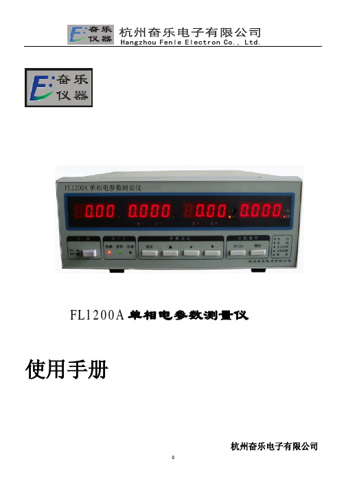
奋乐 FL1200A 单相电参数测量仪 使用手册说明书
2
目录
序言
概述
4
旧包装盒的处理
4
您的产品
正面状态下
5
反面状态下
6
主要特点
7
仪表安全指标
8
技术指标
8
仪器的使用注意事项
8
仪器的保养
FL1200A 单相电参数测量仪
使用手册
杭州奋乐电子有限公司
0
单相数字功率表 使用说明
感谢您购买杭州奋乐电子有限公司生产的 FL****系列单相电参数测量仪产品,为正确使用您 的产品,请仔细阅读本手册并将其妥善保管,以便日后查阅之用。
杭州奋乐电子有限公司 电话:0571-89969323 传真:0571-89969323 地址:杭州市拱墅区拱康路瓜山东苑 72 号 网址: E-Mail: hzfenle@
◆转换键(PF/Hz):功率因数值和频率值相切换显示。
◆ 设定键:按下该键,设定仪表的参数。具体如下 : 1、A--L:设定电流下限 “▲”“●”“ ”切换
2、A--H:设定电流上限“▲”“●”“ ”切换
3、P--L:设定功率下限 “▲”“●”“ ”切换
9
▼▼▼
▼
▼ ▼ ▼
4、P--H:设定功率上限 “▲”“●”“ ”切换 当设定功率时可以用“锁存键”来切换“W”和“kW” 5、Beep: 设定蜂鸣器是否报警,即设定蜂鸣器是否响与不响,OFF 表示关,ON 表示开(出
3
序言
概述 新型单相系列电参数测量仪,外壳采用超薄机箱,重量轻,便于携带。
c2500d5a说明书

苛刻条件。
安装参数
最小通风量(m3/s)30.5最小机房面积(mm)9000×6000×3500(L-W-H)
燃烧空气量(m3/s) 2.61导风管长度(mm)600
最小进风面积(m2)8.8离地高度(mm)≈700
最小排放面积(m2) 6.8排烟管高度(mm)3000
水箱排风口尺寸(mm)2340×2415水泥地基厚度(mm)>150
日用油箱容量(L)1000最大背压(k Pa) 6.7注:安装应根据现场情况因地制宜,表中的安装数据除设备固定参数,其他为康明斯公司建议的常规数据,请用户知悉。
----------------------
柴油机技术说明
对于技工岗位的工程师,请向当地服务中心获取专业维修资料和参考内容。
-康明斯是全球大马力柴油机家族中维护和维修成本最低、最耐用的产品之一。
-基于极其成功的康明斯系列结构设计,增加柴油机排量,提升其功率。
-成熟可靠的技术使康明斯被大量运用于全球矿用、港口、建筑、发电机组等移动式和固定式设备。
-康明斯对其专利的PT燃油系统进行了优化,设计了新型的喷油器和凸轮轴,提升了喷油雾化质量,提高了燃油效率和其经济性。
-拥有康明斯全球统一标准的通用货源,同时延续了模块化结构,使维护和维修成本更低。
-柴油机启动性能优异,瞬态响应快,性能卓越,让用户用电高枕无忧。
A-100功放操作使用说明书

A-100 多功能立体声音频功率放大器操作使用说明书序言欢迎选购中大音响的 A-100高保真音频放大器。
经过我们的精心设计,本品能产生无与伦比的超值享受,同时还能高保真的再现您所喜爱的音乐。
为了确保您能熟悉本品提供的功能,我们建议您在安装和使用前,请仔细阅读本说明书的内容。
产品介绍:这个功放的大致架构就是专为了整合PC-HIFI而设计,近年来随着电脑和互联网的普及,丰富的网络资源,免费的网络音乐共享,让我们的生活越来越离不开电脑了,然而,普通的电脑硬件加上普通的有源电脑音响也就不能满足人们对高品质音乐的需求了。
PC HIFI也就应运而生了。
何谓PC HIFI?实际上就是撇开电脑本身的集成声卡,利用数字信号传输音源到外置声卡或者解码器作为高品质音源,再由专门的功放驱动音箱,这样声音效果相比普通电脑的有源音响就有了质的提升。
中大音响的A-100就是在这样的大环境下立项的,这个项目的解码部分将采用最经典的数字芯片加上专门为之独特设计的外围及后续电路,把来自电脑USB的音源转换成高品质高保真音频模拟信号,传送给功率放大电路进行足功率放大后驱动音箱,还原高素质音乐。
功放电路将采用中大独自开发的经典电路,每声道一对大功率IRFP240/9240做为后级放大,这个管子非常好声,素有甜美、厚声之美誉,曾经被PASS先生在他的很多机型上应用,也被无数PASS迷所采用。
本功放的设计最大功率80瓦,峰值功率达100瓦,驱动一般的书架音箱组建高素质的PC HIFI非常合适。
中大音响在设计上从来都是不惜成本的,就连一个旋钮都是特殊定做的铝合金喷砂旋钮,非常发烧高档,A-100高保真放大器采用中大音响自主设计并开模冲压的纯铝合金拉丝氧化机箱,非市面那些型材拼凑,底板厚度达到4mm,功率管直接安装在底板上进行散热,热稳定性非常高,这样的设计可以保证整机功放管始终工作在一个非常一致的温度范围上,为充分发挥管子的特性奠定了基础。
菲尼克斯5100说明书
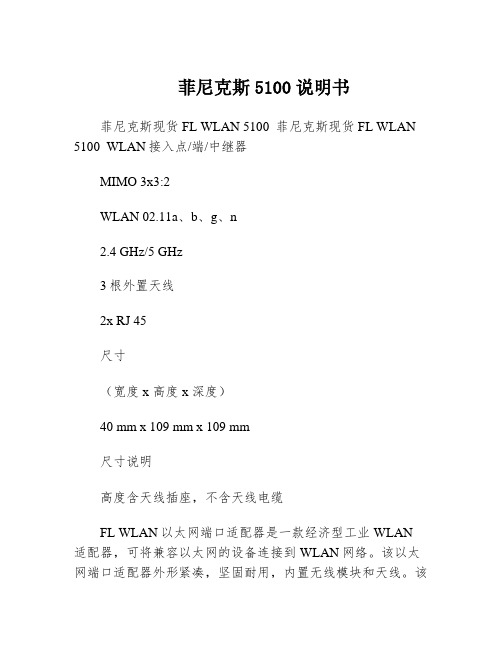
菲尼克斯5100说明书菲尼克斯现货FL WLAN 5100 菲尼克斯现货FL WLAN 5100 WLAN接入点/端/中继器MIMO 3x3:2WLAN 02.11a、b、g、n2.4 GHz/5 GHz3根外置天线2x RJ 45尺寸(宽度 x 高度 x 深度)40 mm x 109 mm x 109 mm尺寸说明高度含天线插座,不含天线电缆FL WLAN以太网端口适配器是一款经济型工业WLAN 适配器,可将兼容以太网的设备连接到WLAN网络。
该以太网端口适配器外形紧凑,坚固耐用,内置无线模块和天线。
该设备防护等级达IP65,可直接现场安装,通过带M12连接器的以太网电缆连接到自动化设备。
优势:可直接在集成到应用以太网端口适配器的主要应用领域安装快捷轻松安装在现场以太网端口适配器是一种简易解决方案,可轻松将带以太网接口的工业自动化设备连接到WLAN网络。
该设备防护等级达IP65,可直接现场安装,通过带M12连接器的以太网电缆连接到自动化设备。
优势:内置天线的紧凑型IP65模块用于以太网和电力传输的M12接口轻松安装在现场自动组态,调试更简单安全通过Mode按钮轻松组态使用Mode按钮,无需组态即可轻松快速地构建安全的点到点网络和小型网络。
此外,也可通过网络浏览器轻松组态。
通过AT命令进行高级设置轻松组态和控制FL EPA 2在WLAN EPA模块运行过程中,可通过控制器发出的简单AT命令对其进行自动组态和控制。
这样就可以通过移动系统的控制器根据位置对漫游过程(即接入点之间的转换)进行控制。
FL EPA产品一览特性FL EPA 2FL EPA 2 RSMAWLAN标准IEEE 02.11a/b/gIEEE 02.11 a/b/g频段和道(*依不同国家而定)2.4 GHz,1-11道5 GHz:36-140道(端)5 GHz:36-4道(接入点)2.4 GHz,1-11道5 GHz:36-140道(端)5 GHz:36-4道(接入点)大数据速率(总值)54Mbps54 Mbps大数据流量(净值)< 20 Mbps< 20 Mbps运行模式端(单端网桥、多端网桥)(微型接入点)两个FL EPA模块之间的无线网桥端(单端网桥、多端网桥)(微型接入点)两个FL EPA模块之间的无线网桥大传输功率2.4 GHz:17 dBm(包括天线)5 GHz:15 dBm(包括天线)2.4 GHz:17 dBm(包括天线)5 GHz:15 dBm(包括天线)天线数1(内置)1(外置),RSMA接口安装后的防护等级IP65IP65环境温度(工作)-30°C … 60°C … 65°C电源9 … 30 V DC,大1.7 W9 …30 V DC,大1.7 W特殊性能双无线板:WLAN和蓝牙双无线板:WLAN和蓝牙功能强大的WLAN IEEE 02.11n模块,通范围更广采用新标准和MIMO技术,扩展通范围该设备有*的无线号,并采用符合IEEE 02.11n标准的MIMO(多点输入,多点输出)多天线技术,可在长距离范围内实现稳定、高速且可靠的无线通。
NS4150B 单声道 D 类音频功率放大器说明书

NS4150B 3.0W单声道D类音频功率放大器1特性●工作电压范围:3.0V~5.0V●输出功率:2.8W(5V/4Ω,THD=10%)●0.1%THD(0.5W/3.6V)●高达88%的效率●高PSRR:-80dB(217Hz)●无需滤波器Class-D结构●优异的全带宽EMI抑制能力●优异的“上电,掉电”噪声抑制●低静态电流:4mA(3.6V电源、No load)●过流保护、过热保护、欠压保护●MSOP8封装2应用范围●平板电脑●行车记录仪●蓝牙音箱3说明NS4150B是一款超低EMI、无需滤波器3W单声道D类音频功率放大器。
NS4150B采用先进的技术,在全带宽范围内极大地降低了EMI干扰,最大限度地减少对其他部件的影响。
NS4150B内置过流保护、过热保护及欠压保护功能,有效地保护芯片在异常工作状况下不被损坏。
并且利用扩频技术充分优化全新电路设计,高达90%的效率更加适合于便携式音频产品。
NS4150B无需滤波器的PWM调制结构及增益内置方式减少了外部元件、PCB面积和系统成本。
NS4150B提供MSOP8封装,额定的工作温度范围为-40℃至85℃。
4典型应用电路5管脚配置MSOP-8的管脚图如下图所示:注:超过上述极限工作参数范围可能导致芯片永久性的损坏。
长时间暴露在上述任何极限条件下可能会影响芯片的可靠性和寿命。
7电气特性工作条件(除非特别说明):T=25℃,VDD=4.8V。
8典型特性曲线下列特性曲线中,除非指定条件,T=25℃。
9应用说明9.1芯片基本结构描述NS4150B是一款超低EMI、无需滤波器3W单声道D类音频功率放大器。
在5V电源下,能够向4Ω负载提供3W的功率,并具有高达90%的效率。
NS4150B采用先进的技术,在全带宽范围内极大地降低了EMI干扰,最大限度地减少对其他部件的影响。
NS4150B无需滤波器的PWM调制结构及增益内置方式减少了外部元件数目、PCB面积和系统成本,利用扩展频谱技术充分优化全新电路设计。
Ophir RF 5100F RF 功率放大器说明书
OWNER’S MANUALModel 5100F RF POWER AMPLIFIER 0.8 – 2.5 GHz, 25 WattsOphir RF5300 Beethoven Street Los Angeles, CA 90066 USATel.: (310) 306-5556FAX: (310) 577-9887 E-mail: ***************** Website: OM_5100F 12/12/011981___________________________________________________ CertificationOphir RF certifies that this product met its published specifications at the time of shipment from the factory._____________________________________________________________________ WarrantyThis Ophir RF product is warranted against defects in material and workmanship for a period of two (2) years from date of receipt. During the warranty period, Ophir RF, will,at its option, either repair or replace products that prove to be defective. For warranty service or repair, this product must be returned to a service facility designated by Ophir RF.Limitation of WarrantyThe foregoing warranty shall not apply to defects resulting from improper orinadequate maintenance by Buyer, Buyer-supplied software or interfacing,unauthorized modification or misuse, operation outside of the environmentalspecifications for the product, or improper site preparation or maintenance.NO OTHER WARRANTY IS EXPRESSED OR IMPLIED. OPHIR RF SPECIFICALLY DISCLAIMS THE IMPLIED WARRANTIES OF MERCHANTABILITY AND FITNESS FOR A PARTICULAR PURPOSE.Exclusive RemediesTHE REMEDIES PROVIDED HEREIN ARE BUYER’S SOLE AND EXCLUSIVEREMEDIES. OPHIR RF SHALL NOT BE LIABLE FOR ANY DIRECT,INDIRECT, SPECIAL, INCIDENTAL, OR CONSEQUENTIAL DAMAGES, WHETHER BASED ON CONTRACT, TORT, OR ANY OTHER LEGAL THEORY._____________________________________________________________________ AssistanceFor any assistance, contact your Ophir RF Sales and Service Office.OM_5100F 12/12/01 Page 1 of 14_____________________________________________________________________ Safety InformationThe following safety notes and symbol are used in this manual and on the equipment. Familiarize yourself with each and its meaning before operating this equipment.Caution Caution denotes a hazard. It calls attention to a procedure that, if not correctly performed or adhered to, would result in damage to, ordestruction of, the equipment. Do not proceed beyond a caution noteuntil the indicated conditions are fully understood and met._____________________________________________________________________ Warning Warning denotes a hazard. It calls attention to a procedure which, if not correctly performed or adhered to, could result in injury or lossof life. Do not proceed beyond a warning note until the indicatedconditions are fully understood and met._____________________________________________________________________The instruction documentation symbol. The product is marked with thissymbol when it is necessary for the user to refer to the instructions in thedocumentation._____________________________________________________________________ General Safety ConsiderationsWarning This is a safety Class I product provided with a protective earthing ground incorporated in the AC power cord. The AC power cordshall only be inserted in a socket outlet provided with a protectiveearth contact. Any interruption of the protective conductor, insideor outside of the equipment, is likely to make the equipmentdangerous. Intentional interruption is prohibited._____________________________________________________________________ Warning No operator serviceable parts inside. Refer servicing to qualified personnel. To prevent electrical shock, do not remove covers._____________________________________________________________________ Warning If this equipment is used in a manner not specified by Ophir RF, the protection provided by the equipment may be impaired._____________________________________________________________________ Caution Before switching on this equipment, make sure that the line voltage is correct and that an External Load has been applied. (Refer to 2.2.3)OM_5100F 12/12/01 Page 2 of 14ContentsSection PageInformation 5I GeneralDeclaration of Conformity 5Scope 5Description 5Equipment Specifications 6II Installation 7Incoming Inspection 7Preparation for Use 7Power Requirements 7Earthing 7Load Requirements 7Connections 7CableIII Operation 8Introduction 8AgainstUnspecified Use 8StatementControls, Indicators, and Connectors 8Basic Operating Procedures 8Before Turn On 8Turn On 9Operation 9Turn Off 9IV Maintenance 1010IntroductionTest 10PerformanceProcedures 10AdjustmentProcedures 10TroubleshootingImproper Power Distribution 10Low or No RF Output Power 10Cleaning 10Service 11V CustomerServicing 11Return11(RMA)MaterialAuthorizationShipment11forRepackaging12FormRequestRMAOM_5100F 12/12/01 Page 3 of 14Figuresdiagram 131 BlockFigureFigure 2 System View 14Tables6TableSpecifications1 EquipmentOM_5100F 12/12/01 Page 4 of 14SECTION IGeneral Information1.1 Declaration Of ConformityDECLARATION OF CE CONFORMITYOphir RF Inc., 5300 Beethoven Street, Los Angeles, CA 90066, declares under sole responsibility that the RF Power Amplifier, Model 5100F, to which this declaration relates, meets essential health and safety requirements and is in conformity with ISO 3864. The CE marking has been applied according to the relevant Safety and CE Directives listed below using the relevant section of the following EC standards and other normative documents:EU EMC DIRECTIVE 89/366/EEC - Essential health and safety requirements relating to electromagnetic compatibilityENEN55022 Class BEN50082-1 EC generic immunity requirements, Category A & BIEC801-2, IEC801-3, IEC801-4EC Low Voltage Directive 72/23/EEC Essential health and safety requirements relating to electrical equipment designed for use within certain violate limits.EN61010-1 Safety requirements of Test Measurement and LaboratoryEquipment.1.2 ScopeThis owner’s manual contains operating instructions for a model 5100F amplifier.1.3 DescriptionThe power amplifier operates in the RF frequency. The input to the power amplifier is rated at 0 dBm nominal CW signal between the 0.8 – 2.5 GHz frequency range. The output of the power amplifier is specified at 25 Watts CW RF signal. Detailed specifications for the power amplifier are given in table 1-1. OM_5100F 12/12/01 Page 5 of 14Equipment SpecificationsTable 1-1. Specifications @ 25º COperation:A/ABofClass2.5GHz–Range:Frequency0.8Output Power @ Saturation: 25 Watts CW TypicalOutput Power @ 1 dB Compression: 20 Watts CW minimumdB+45minimumGain:SmallSignalSmall Signal Gain Flatness: ± 2.0 dB maximumnominalohmsInput/OutputImpedance:50Input VSWR: 2:1 maximumdBmInput +10RFMax.Operating Temperature Range: 0º C to 50º COperating Humidity Range: 95%, Non-condensingTemp. Protection: Shut down @ 80º C minimumAirForcedCoolingsystem:InternalAC Input: 100 - 240 VAC, 50/60 Hz, 1¯Wattsmaximum200ACPower:InputDimensions: 19" W x 3.5" H x 18" DmaximumPoundsWeight: 30Option(s) included:-Type-N Connectors on Front Panel.*NOTE – Specifications subject to change without noticeOM_5100F 12/12/01 Page 6 of 14SECTION IIInstallationInspection2.1 IncomingWARNING!Do not apply power until you have read Sections II and III and you have performed all specified procedures. If you fail to observe this warning, damage to the equipment and/or bodily injury may result.The power amplifier has been mechanically and electrically inspected prior to shipment. If the equipment has been damaged or if electrical performance is not within specification, notify the carrier and OPHIR RF immediately.2.2 Preparation For Use2.2.1 Power RequirementsThe power amplifier requires a power source of 100 – 240 VAC, 50/60Hz capable of delivering 200 Watts. Turn off the front panel ‘ON/OFF’switch before connecting the AC power source.2.2.2 EarthingEarthing is achieved simultaneously with connection of the AC powercords to a properly grounded power source.2.2.3 Load RequirementsThe power amplifier requires a load, antenna, or dummy load with a 50-Ohm nominal impedance.CAUTION!Make this external load connection before applying any power to theequipment.2.2.4 Cable ConnectionsThe AC power cable connection is made at the rear of the poweramplifier via the receptacle connector. RF connections for Input andOutput are made at the front via Type-N connectors. (Refer to Figure 2) OM_5100F 12/12/01 Page 7 of 14SECTION IIIOperation3.1 IntroductionThis section describes the operating controls and procedures of the power amplifier.3.2 Statement Against Unspecified UseThis amplifier must be used as specified by the manufacturer. Use of this equipment in any way not specified by the manufacturer may result in bodily injury and/or damage to the equipment.3.3 Controls, Indicators, and ConnectorsWhen set to ‘ON’, the ON/OFF switch will light indicating that AC power is present. The RF INPUT and OUTPUT connections are located on the front of the power amplifier. Refer to figure 2 and the following discussion for the location and functional description of all controls, indicators, and connectors.3.4 Basic Operating ProceduresNOTE!The operation of the power amplifier is passive; that is, after an External Load and Input power have been applied, no procedures other than turn off are required.3.5 Before Turn OnCAUTION!Do not obstruct the airflow at the front and rear of the power amplifier. If you do not verify that this equipment has an unobstructed airflow, you may cause this equipment to overheat or otherwise impair its operation.Perform the following preliminary procedures before energizing the equipment:a. Check that the ON/OFF switch is set to the ‘OFF’ position.b. At the rear of the RF power amplifier, verify that the AC cord is properlyinserted into the receptacle connector.c. Verify that 50 ohm loads are connected to the RF Input and Output ports.3.6. Turn OnPerform the following procedures to energize the equipment:a. Set the ON/OFF switch to the ‘ON’ position. Verify that the green switchlamp is lit.b. Apply RF power.OM_5100F 12/12/01 Page 8 of 14CAUTION!To maintain specified performance and retain certain operating characteristics, RF input power should not exceed +10 dBm.3.7. Operation3.7.1 ON/OFF SwitchIn the ‘ON’ position, AC power is supplied to the power amplifier.3.7.2 ON/OFF Switch LampLights to indicate the distribution of AC power throughout the poweramplifier.3.7.3 TEMP. FAULT IndicatorLights at an internal temperature exceeding 80º C with the amplifierturning off DC bias voltage to the main amplifiers’ modules. DC biasvoltage will automatically return at temperatures below 75º C.Off.3.8 TurnWARNING!In the event of ANY power failure, whenever possible and practical, it is advisable to reset the ON/OFF switch on the front panel to the “OFF”position before y ou reconnect AC power to the power amplifier. This is to prevent any possible electrical damage to the amplifier, due to the initial power surge, once power is restored.Turn off the RF power amplifier by first lowering or removing the RF Input drive level and then placing the ON/OFF switch in the ‘OFF’ position.OM_5100F 12/12/01 Page 9 of 14Maintenance4.1 IntroductionThis section describes the performance tests, adjustments and troubleshooting procedures for the power amplifier.4.2 Performance TestThe performance test is identical to the operating procedure described in Section III.4.3 Adjustment ProcedureThere are no operator adjustments applicable for the power amplifier.4.4 Troubleshooting ProcedureNOTE!Troubleshooting beyond the level described in this procedure must be performed at an authorized service facility or the warranty may be voided.The following troubleshooting procedure is to be used as a guide to help ascertain whether the equipment is malfunctioning.4.4.1 Improper Power DistributionWhenever there appears to be improper power distributed throughout theamplifier, perform the following steps:a. Verify the ‘ON/OFF’ switch lamp is illuminated on the front panel.b. Verify that the internal fans are operating.c. If neither step A or B above appear to be working, verify the presenceof AC power at the source and also at rear panel connection.4.4.2 Low or No RF Output PowerWhenever the RF output power of the amplifier and/or the current drawnfrom the power supply is low, or the operating temperature has exceeded80°C, the system may have triggered the thermal protection function.Perform the following procedure:a. Verify that the drive level is correct.b. Check that the ‘TEMP. FAULT’ indicator is not illuminated.If the above conditions are verified and there is still low or no RF outputpower, then contact your nearest authorized Ophir RF Service Center. 4.5. CLEANINGUse a rag with isopropyl alcohol to clean exterior surfaces. Use a vacuum to remove dust from the screens on the front and rear of the equipment.Customer Service5.1 ServicingAll servicing and repair must be done by an authorized repair and servicing facility.5.2 Return Material Authorization (RMA)In the unlikely event you experience equipment difficulties that can not be resolved without opening up the equipment, you will need to obtain authorization and an RMA number prior to returning the equipment.NOTE!It is Ophir RF’s policy not to accept any returned equipment without an authorized RMA number!5.3 Repackaging for Shipment.WARNING!It is always recommended that two people carry this system due to its weight.Use the original shipping container and packing materials if possible. If these have been discarded or are not in good condition for reuse, use a heavy-duty carton capable of providing adequate protection. Whenever the amplifier is being returned to the manufacturer, attach an identifying tag, indicating the RMA number, on the outside of the container.Wrap the equipment in heavy paper or plastic, and use enough shock-absorbing material (3 to 4-inch layers) around all sides to provide a firm cushion and to prevent movement within the container. Protect the front and rear panels with cardboard or foam blocks. Seal the shipping container securely and mark the container "FRAGILE".To receive your RMA number, contact our customer service department.Customer ServicePhone: 310-306-5556Fax: 310-577-9887Email: ***************************You will be required to complete a simple questionnaire prior to receiving your RMA number. Once you have your RMA number, you are authorized to return your equipment.To help you expedite this process, we have included a copy of the form you will be required to complete prior to receiving your RMA number.5300 Beethoven Street, Los Angeles, CA 90066Tel: (310) 306-5556 • FAX (310) 577-9887 •e-mail:***************************RMA REQUEST FORMRMA NUMBER:NAME:CUSTOMERRECEIVEDROM RESS:F ADD(STREET ADDRESS – INCLUDING SUITE OR M/S NUMBER)(CITY – STATE – ZIP OR COUNTRY CODE) (COUNTRY)RETURN TOADDRESS:(STREET ADDRESS – INCLUDING SUITE OR M/S NUMBER)(CITY – STATE – ZIP OR COUNTRY CODE) (COUNTRY)CONTACT PERSON:(FIRST AND LAST NAME) (TITLE/RANK)(TELEPHONE) (FAX)(E-MAIL)MODEL NUMBER SERIAL NUMBERREASON FOR RMA:PLEASE FAX THIS FORM TO OPHIR RF, INC.AT (310) 577-9887 ATTN: CUSTOMER SERVICETHERE IS A $500 MINIMUM EVALUATION CHARGE FOR ALL NON-WARRANTY REPAIRS. PURCHASE ORDER TO BE PRESENTED PRIOR TO COMMENCEMENT OF REPAIRS. FOLLOWING EVALUATION, THE COST OF REPAIRS WILL BE SUBMITTED FOR YOUR APPROVAL AND PURCHASE ORDER AMENDMENT.DO NOT SHIP AMPLIFIERS C.O.D. – OPHIR RF WILL NOT ACCEPT ANY C.O.D. SHIPMENTS. PLEASE CALL US WITH ANY SHIPPING QUESTIONS.。
液晶AV驱动板规格书-AdafruitIndustries
液晶驱动板规格书产品名称 PCB-800099驱动板文件编号 TYT20120909供应商:深圳市天宇朗通科技有限公司地址:深圳福田区振华路高科德电子市场42073联系人 张先生客户名称:客户地址:联系人文件级别 公共文件发布日期2012-09-091.产品说明:本驱动板可以1,1路VGA信号输入2,2路A V信号输入3,1路HDMI信号输入,且本IC支持的是HDMI1.14,1路倒车信号输入5,支持宽电压输入,并可以在,5V-24V之间正常工作,6,标准背光6PIN,接口,可外接高压板7,驱动板集成液晶屏LED背光驱动板路,8,标准LVDS信号输出,可支持单6,单8,双6,双8等标准的LVDS信号的液晶屏,但只支持屏供电为3.3V的液晶屏9,标准按键板接口,并支持双色LED指示灯显示10,支持TTL信号输出,可支持AT070TN92,AT065TN14AT080TN52AT090TN12AT090TN10AT070TN90AT070TN93AT070TN94等,通用50PIN接口的TTL液晶屏11,配合本公司编号为PCB800100的液晶屏转接板,可支持如下液晶屏EJ070NA01-1024X600分辨率EJ080NA04B-1024X768分辨率ZJ070NA01,型号的通用40PIN高分液晶屏12,配合PCB800100,还可以支持4。
3,5,6,7寸,40PIN通用的屏,定义参见AT0543TN24V,113,本驱动板最大输出显示分辨率为,1920X1080超过,1440X900显示分辨率时,需要视IC的工作情况,增加散热片,以降低IC的工作温度)14本IC,VGA部分可以直接输入YPBPR信号,通过程序实现15,本驱动板可增加遥控功能(需要通过软件实现)16,本驱动板可以自动检测,并显示相关的输入电压信息-----注,此功能为定制功能,需要联系我公司技术部17,本驱动板可以支持自动检测信号开关机功能,--此功能为定制功能18,本驱动板可以加BNC接口---需要定制19,支持倒车控制,并显示A V2上,倒车电压支持50V以内的电压输入20,本驱动板定位孔为四个,21,如果特殊要求,我公司可以提供其它的定制服务22,客户需要改程序,需要连接我公司,购买相关的程序下载板,23,利用本公司的USB接口程序下载板,可以自行在BIN代码上添加LOGO6产品尺寸图7接口功能详细说明7.1CON1,接口定义8 运输,存储,使用要求1,不要重压和弯折变形 2,防静电和水3,相对湿度,小于80% 4, 使用温度 -1-度--+60度 5,使用湿度0-+40度。
ES5000说明书(1)
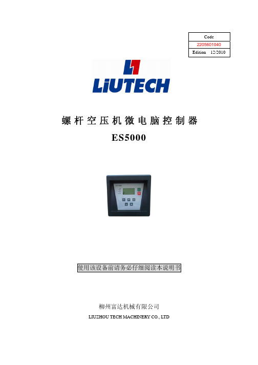
Code2205601040Edition 12/2010螺杆空压机微电脑控制器ES5000使用该设备前请务必仔细阅读本说明书柳州富达机械有限公司LIUZHOU TECH MACHINERY CO., LTD柳州富达机械有限公司公司地址:柳州市阳和工业新区工业园,B-22-1,B-23-1 邮编:545006 商务部电话:(0772)3171004 3172024 3172648 3172248售后服务电话:(0772)3172247 3173004技术部电话:(0772)3591521 3173150传 真:(0772)3171027网 址:授权及服务中心如果机器需要停机或者没有正常运行,请关闭机器但不要试图去修理他。
请联系一个拥有授权的服务中心来修理,并且需要采用原配件。
对本建议的疏忽将会对压缩机设备的安全造成损坏。
说 明请妥善保存本说明书,以便随时查用;本手册是该机器的一部分。
请您务必在使用本机器之前详细阅读本说明书。
.对设备进行的安装以及随后的操作都必须充分地考虑到电气设备的操作规定及个人安全因素。
性能和安全说明使用注意使用前,请仔细阅读使用说明书。
只有专业技术人员允许安装ES5000。
机械安装时务必充分考虑安装位置,确保散热良好和减少电磁干扰。
实施配线时,请按强电、弱电分开布线规则布线,减少电磁干扰。
继电器输出控制之交流接触器等感性负载必须接突波吸收器。
空压机上电之前仔细检查输入/输出配线。
本机体之接地端子正确接地(第三种接地),可提高产品的抗杂讯能力。
电机额定电流(跳机电流)的设定按电机铭牌额定电流╳电机过载倍数/1.2倍特点:● LCD中英文显示.● 远程/本地控制选择/计算机。
● 联动/独立运行选择.● 对温度进行检测与控制保护.● 自动调节负荷率控制压力平衡.● 对电机具有起、停控制、运行控制.● 按MODBUS RTU协议通过RS-485接口,接受外部设备通信命令.● 对电机具有短路、堵转、缺相、过载、不平衡、防逆转等全方位保护功能.● 将检测到的温度与压力信号,转换为4~20mA的模拟量信号,通过模拟量输出端口输出.● 可显示主电机,风扇电机的电流。
日本电友DENYO静音型柴油发电机组技术参数大全
138 138 165 138 165 138 165
165
198
3相4线
(2)双电压系统
0.8(滞后)
±0.5 范围内
无刷,旋转式励磁器(带自动电压调节器 A.V.R.)
F级
Mitsubishi 6D16-TLE2D
Komatsu SA6D102E-1-A
Hino J08C-UD
串列式直喷式,涡轮增压式,后冷式
63 65 61 63
DCA-100ESI
50
60
80 100
88 110
Lsuzu DD-6BG1T
串列式直喷式
涡轮增压式
100/
124/
1500
1800
73.6/
91.3/
1500
1800
6-105×125
6.494
13.5 17.4 22.4 22.0
95D31R×2 225
2750 1050 1350 1730
F级
Yanmar 3TNV84-G
串列式 直喷式
15.3/
18.3/
1500
1800
11.3/
13.5/
1500
1800
3-84×90
1.496
2.1 2.6 6.7 3.9
Kubota D1703-KB
Kubota V2203-KB
Kubota V2203-KB
串列式,涡流室式
Isuzu AA-4LE2 串列式 直喷式
原厂整体设计制造,并非简单在普通发电机组外加装外壳
2、电友 Denyo 发电机组整机为原产地制造并可提供原产地证书。
3、拥有专利技术的无刷式电友 Denyo 发电机是一款具有旋转磁场和自然通风特性的单轴承四级同步交流发电机,配备阻尼绕组以使电压 偏
eterm完整版
1. 航班信息查询AV:城市对/日期/起飞时刻/航空公司代码/经停标志/座位品级“.”表示当天" -是昨天" “+”表示明天“N”表示经停“D”表示直达2.航班经停点及起降时刻的显示 FF:航班号/日期例:FF:1321/19MAY3.票价查询 FD:城市对/航空公司代码例:FD:PEKSHA/CA从已有的AV中查询票价 FD:序号4.订票:(注:请一次性封口)(成人)SD1(航段)Y(舱位)/1(人数)(回车)NM1计算1治理(名字中间用数字1隔开)(回车) TKTL(预按时刻)/1200/19MAY/SIA000(回车)SSR FOID MU HK/NI2(身份证)(回车)CT4524545(联系)(回车)@或\ F12(输入)(儿童)SD1(航段)Y(舱位)/1(人数)(回车)NM1计算CHD1治理CHD(名字中间用数字1隔开,在名字后面加上CHD标志)(回车)TKTL(预按时刻)/1200/19MAY/SIA000(回车)XN:IN/名字INF(诞生月和年)/P1(回车)CT4524545(联系)(回车)@或\ F12(输入)(婴儿)与大人在同一个记录,可是婴儿不占座位(回车) SD1(航段)Y(舱位)/1(人数)(回车)NM1计算1治理(名字中间用数字1隔开)(回车) TKTL(预按时刻)/1200/19MAY/SIA000(回车)XN:IN/名字INF(诞生月和年)/P1(回车)SSR FOID MU HK/NI2(身份证)(回车)CT4524545(联系)(回车)@或\ F12(输入)5.做假RRRTSKIKS(记录编号)(输入)XE(出票时限项)(回车)TKT/00(假票号)(回车)2RR(把航程项做RR) 输入取消整个记录:XEPNR@SKSKI(加记录编号)取消记录中的一个人:XEP1(1代表所取消的第几个人)PNR的历史记录.,先提记录,在RTU1要往下翻页:RTC|记录|PN 若是是记录往下翻:RT记录|PN(注请一次性封口)例: AV查询航班(输入)SD1(航段)Y(舱位)/25(人数)(回车)GN:25kxun (回车)TKTL(预按时刻)/1200/19MAY/SIA000(回车)CT4524545(联系)(回车)@或\ F12(输入)生成记录后在输入名单(注在输入名单的时候最多只能输入一行,然后穿入,不能回车接着输入)团队取消:XEG 取消一人 XEGP1(1是指第几个人)RTN团队记录里已入的名单8.用短信方式通知客人定票信息第一提出记录编号(输入)RMK MP 号码(输入)SMS I/记录编号(输入)9航班时刻显示 SK:选择项/城市对/日期/时刻/航空公司代码/舱位例:SK PEKCAN/19MAY 指定日期前后三天内航班信息10查询三字代码 CNTD:T/BEIJING查询城市名称 CD:PEK11特殊效劳信息(OSI/SSR)国航知音卡SSR FQTV CA HK/NN………/P1特殊餐食的输入法例:SSR SPML CA NN1 LOW SALT/P1例:SSR VGML CA NN1 P1/S2或:SSR SPML CA NN1 PEKSHA CA1501 Y 19MAY LOW SALT/P1餐食代码:SPML 特殊餐食申请 VGML 素食(不含奶,蛋制食物)AVML 亚洲素食 VLML 素食(专门牛奶,蛋)LSML 低盐餐 MOML 穆斯林餐ORML 东方餐 BBML 婴儿,儿童餐CHML 儿童餐申请定位SSR OTHS MU(航空公司代码)KK,V(舱位)THANKS计算功能CO加数天气预报WF加所查城市例:WFSIA12儿童,婴儿及宽免的外交官免税输入方式FM:FCNY…../SCNY…../C…../TEXEMPTCN(注请一次性封口)SD1(航段)Y(舱位)/1(人数)(回车)NM1计算1治理(名字中间用数字1隔开)(回车)TKTL(预按时刻)/1200/19MAY/SIA000(回车)SSR FOID MU HK/NI2(身份证)(回车)CT4524545(联系)(回车)@或\ F12(输入)14国际运价RT记录QTE: 输入注:指令最多能够计算16个航段的运价,当航程段超过8段时,QTE 后,系统不能当即算出其结果,而是给出一个编码,然后再利用XS FSI/编码,找到其结果2.若是利用XS FSI/编码仍然没有结果时,2分钟以后再利用XS FSI/编码提取结果QTE指令的实质是XS FSP或XS FSI指令国际运价NFI显示运价附加规那么:XS FSG2 2是QTE中票价的序号15.注EAS效劳器不支持ES指令不支持TRFD退票指令1.2.进入系统 >$$OPEN TIPC33.2.输入工作号 >SI:工作号/密码4.3.查看PID状态 >DA5.4.退出系统 >SO6.5.修改密码 >AN:旧密码/新密码7.6.随时查看SIGN-IN信息 >SIIF:8.7.指令使用帮助 >HELP: 指令9.8.屏幕向上一页 >PB10.9.屏幕向下一页 >PN11.10.清屏指令 >CP12.11.重复显示当前页 >PG13.12.一屏显示所有内容 >PQ114.查询15. 1. 航班座位可利用显示 >AV: H/城市对/日期/时间/ 航空公司代码(或GDS代码)16. 2. 最早有座位航班查询 >FV: 城市对/日期/起飞时间/座位数/航空公司代码(或GDS代码)/经停标志 / 舱位17. 3. 航班飞行周期的查询 >SK: 城市对/日期/时间/航空公司代码/ 舱位18. 4. 航班经停点和起降时间的显示指令 >FF: 航班号/日期19. 5. 指定日期的航段上的航班详细信息显示 >DSG:C/航班号/座位等级/日期/航段20.或 RT之后, >DSG: 航班序号21.信息查询及辅助功能22.一、24小时北京天气预报 WF >WF 城市三字代码23.二、机场转机信息查询 DSM >DSM: PEK24.三、机场、国家、航空公司代码查询 CNTD/CD25.1)查询城市三字代码>CNTD T/BEIJING26.2)查询城市名称>CD PEK27.3)查询一个国家所有城市>CNTD A/CN28.4)查询国家全称>CNTD C/CN29.5)查询国家两字码>CNTD N/CHINA30.6)查询航空公司信息>CNTD D/CA31.7)查询航空公司两字代码>CNTD M/AIR CHINA32.四、计算CO33.1)四则运算>CO 100+234.2)计算北京和巴黎的时差>CO T/PEKCDG35.3)显示巴黎10月1日0点的GMT标准时刻>COT/CDG/1OCT/000036.4)英里换算成公里>CO K/英里数37.5)公里换算成英里>CO M/公里数38.五、日期查询DATE39.1)显示当前日期和星期几>DATE40.2)显示10天,90天后的日期>DATE 10/9041.3)显示2004年1月1日的前2天,及后20天的日期>DATE1JAN04/-2/2042.六、时间查询TIME43.1)显示当前时间>TIME44.2)北京时间2004年1月1日零点的巴黎时刻>TIME1JAN04/0000/CDG45.3)纽约时间2004年1月1日零点的北京、巴黎时刻>TIMENYC/1JAN/0000/PEK/CDG46.七、长度、重量、温度换算 CV47.1)100公里换算成英里>CV 100KM48.2)100英里换算成公里>CV 100MI49.3)摄氏35度转化为华氏度>CV 35C50.4)华氏95度转化为摄氏度>CV 95F51.5)10英镑转化为公斤>CV 10LB52.6)10公斤转化为英镑-磅>CV 10KG53.八、查询中文信息YI54.1)显示所有静态信息的目录>YI55.2)显示不含副标题的公告>YI标题56.3)显示有副标题的公告>YI I/某标题57.九、旅游信息查询TIM58.1)查询签证信息>TIM TIFV59.2)查询健康检疫信息>TIM TIFH60.3)同时查询签证、健康检疫信息 >TIM TIFA61.4)查询与出入境有关的信息>TIM TIDFT/城市/章节/小标题/页码62.5)显示TIM帮助功能>TIM TIHELP63.6)显示TIM中有关规则>TIM TIRULES64.7)显示综合旅游信息新闻>TIM TINEWS65.8)显示下一页>TIPN66.9)显示上一页>TIPB67.68.成立PNR69.一、航段预订70.1)直接建立航段组 SS>SS CA1537/Y/1OCT/PEKNKGNN1/1225140071.2)间接建立航段组 SD>AV PEKCAN72.>SD 1Y173.3)OPEN航段的建立 SN>SN YY/F/PEKCAN74.>SN CZ/F/PEKCAN75.4)ARNK段的建立 SA >SA TSNPEK76.5) 旅客行程提示>SA MU5119Y1OCT SHAPEK HK77.6)调整航段顺序 CS>CS 2/178.二、姓名输入 NM79.1)英文姓名的输入>NM 1STEPHEN/HAETTI 1ZHU/QI80.2)同姓旅客英文名的输入>NM 2ZHANG/JIAN/QIANG81.3)中文姓名的输入>NM 1杨振振 1马永82.4)无人陪伴儿童姓名输入>NM 1马晓涌(UM4)83.5)带一个婴儿的成人输入姓名>NM 1马永84.>XN IN/马晓涌INF(MAR01)P185.6)建立一个团名为CHANGYOU的12人的团体PNR>GN12CHANGYOU86.三、联系方式 CT >CT PEK/123456787.四、证件信息输入 SSR (注意:CA表示相应的航空公司代码)88.1) 国内旅客 >SSR FOID CA HK/证件代码及号码/Pn 证件种类代码:NI-身份证; PP-护照; ID-其他证件89.2) 国际旅客>SSR PSPT CA HK/护照号码/国籍/旅客生日/旅客姓/旅客名/性别及婴儿标识/持有人标识/Pn90.注:下划线部分为必输项91.五、出票时限 TKTL>TK TL/1200/01OCT/BJS12392.六、手工票号输入 TKT>TKT/49/P193.七、票价信息的简易输入 FC/FN 八、选择制定航段进行票价计算或打票SEL>SEL: 指定航段序号94.九、国内BSP客票自动生成FN/FC/FP项:>PAT:95.十、国际客票经过QTE/XS FSQ, 自动生成FN/FC项: >DFSQ:96.十一、付款方式组 FP>FP:CASH/ CHECK,CNY97.十二、签注信息组 EI 十三、旅游代码组 TC (一般按照航空公司要求输入) 十四、打票预览 TKTV>TKTV: 打票机序号98.十五、票号自动传输 STN>STN: 票号/Pn/指定航段序号99.十六、客票打印 DZ100.打印PNR中所有人的客票>DZ:1101.仅打印第一个成人所携带的婴儿客票>DZ:1/P1, INF102.仅打印第一个成人的客票>DZ:1/P1, ADL103.打印PNR中所有婴儿客票>DZ:1,INF104.打印PNR中所有成人客票>DZ:1, ADL105.106.特殊效劳 SSR107.一、查看航班座位图ADM>ADM:航段序号/航段108.二、进行机上座位预订 ASR>ASR: 航段序号/座位号109.三、里程输入 >SSR FQTV承运航空公司代码HK1/发卡航空公司代码卡号/Pn110.四、其他特殊服务的申请111.>SSR 特殊服务代码航空公司 NN数量/Pn/Sn112.经常使用特殊效劳代码:113.机位申请114.NSSA:无烟靠走廊的座位 NSSW:无烟靠窗的座位115.NSST:无烟座位 SMSA:吸烟靠走廊的座位116.SMSW:吸烟靠窗的座位 SMST:吸烟座位117.特殊餐食118.AVML:亚洲素食 BLML:流食119.CHML:儿童餐 DBML:糖尿病患者餐120.FPML:水果拼盘 SFML:海洋餐121.HFML:高纤维餐 HNML:印度餐122.BBML:婴儿餐 KSML:犹太教餐123.LCML:低卡路里餐 LFML:低胆固醇、低脂肪餐124.LSML:无盐餐 MOML:穆斯林餐125.VLML:素食(含糖、鸡蛋) VGML:素食(无糖)126.其他127.PETC:宠物(需要详细说明) BSCT:摇篮车/吊床/婴儿摇篮128.BIKE:自行车(须说明数量) SLPR:机舱内床铺(不包括担架)129.BLND:盲人旅客(如果有导盲犬或其他动物陪伴,须详细说明) 130.BULK:超大行李(须说明数量、重量和尺寸)131.CBBG:放置机舱行李(购买了额外座位,须说明数量,重量及尺寸)132.DEAF:聋哑旅客(如果有助听狗或其他动物陪伴,须详细说明) 133.DEPA:被驱逐出境(有人陪伴) DEPU:被驱逐处境(无人陪伴)134.XBAG:额外行李(须说明数量、重量和尺寸)135.FRAG:易碎行李(须说明数量、重量和尺寸)136.MEDA:健康状况(需要旅客医疗状况证明)137.SPEQ:体育设施(须指明设备类型、数量、重量和尺寸)138.STCR:担架旅客 UMNR:无人陪伴儿童139.140.PNR提取和修改141.一、PNR提取142.1)记录编号提取PNR >RT 记录编号143.2)根据旅客名单提取PNR >RT旅客姓名/航班号/日期144.3)提取完整PNR >RT C/记录编号145.4)提取PNR的历史部分 >RT U146.5)返回到PNR的现行部分 >RT A147.6)按照航班的旅客名单提取>ML C/CA1301/10DEC >RT 序号148.7) 提取本部门在该航班的所有订座记录(RR、HK、HN、HL、HX)>ML C/CA1321/7OCT149.8)提取所有团体PNR记录>ML G/CA1321/7OCT150.9)提取所有订妥座位的记录>ML B/CA1321/7OCT151.10)提取所有未证实座位的记录>ML U/CA1321/7OCT152.11)提取所有非团体PNR记录>ML NG/CA1321/7OCT153.二、国内航空公司记录的提取和转换154.>RRT: V/航空公司记录编号/航班号/日期155.>@OK156.三、记录分离SP >SP 1/3157.四、记录修改158.1)旅客姓名修改>1/1杨振159.2)删除姓名组以外的内容>XE 序号160.3)取消PNR>XEPNR@161.五、记录封口 @162.1)正常封口>@163.2)以下几种情况可使用@K封口>@K164.a)将KK,KL或TK变为HK165.b)将UU,US或TL变为HL166.c)将TN变为HN167.d)将带有NI,UC,UN的项移到PNR的历史部分168.3)以下情况可使用@I封口>@I169.a)航段不连续170.b)有航班变更标识171.c)两个连接航段的停留时间小于最小连接时间172.发布运价的查询173.一、国内公布运价查询:174.1).查询城市对间当前可用票价FD175.>FD:城市对/日期/航空公司代码/查询选项(S排序由低到高;L最低价)176.2).运价限制条件信息查询PFN177.>PFN: 规则号/ 承运人或在FD的基础上 >PFN: 运价序号178.3).查询运价的航线限制 PFR179.在FD基础上有航线限制标识的情况下 >PFR: 运价序号180.二、航空公司净价查询:(需要航空公司授权)181. 1.查询运价总则 >NFN:GR00/CA182. 2.按城市对查询票价信息: >NFD:PEKLON/CA183. 3.指定旅行日期查询: >NFD:PEKLON/21MAY04/CA184. 4.查询单程票价 >NFD:PEKLON/CA*OW185. 5.查询M舱票价 >NFD:PEKLON/CA#M186. 6.查询运价基础为HIT的票价 >NFD:PEKLON/CA@HIT187.7.查询学生票价 >NFD:PEKLON/CA*SD188.8.查询团队票价 >NFD:PEKLON/CA*GC189.9.显示第3条票价的规则限制 >NFN:3190.10.显示第3条票价的航线规定 >NFR:3191.11.显示第4条票价的签注信息 >NFE:4192.12. 修改查询条件,快速重新查询票价: >NFC:193.13.指定航线查询 >NFQ:PEK15MAY04LONPEK/CA194.14. 按协议查询 >NFL:/CA195.15. 显示第2条协议的内容 >NFL:2196.16.显示第2条协议中的所有票价 >NFL:2*ALL197.操作流程示例:198.某北京旅客要在5月1日去新加坡或吉隆坡,5月7日回北京,希望取得最廉价的来回客票。
FD470中文资料

FICHE TECHNIQUEFD400 RELAIS HERMETIQUE 2 RT DOUBLE COUPURE10 A/56 VccNOTES D'APPLICATION:001007SOCLE ASSOCIE:SFD400CE40ERelais hermétique monostable polariséCombinaison des contacts 2 R(DC) + 2 T(DE)Alimentation bobine Courant continuCARACTERISTIQUES TECHNIQUES PRINCIPALESPrévu pour commuter10 A / 56 VccMasse80 g maxDimensions max. du boîtier enmm26 x 25,7 x 26Armature à forces équilibréesBoîtier métallique hermétique protégé anti-corrosionNon chevauchement des contactsCARACTERISTIQUES ELECTRIQUES DES CONTACTSDurée de vie minimale Tension aux bornes du contact56 Vcc100 000 cycles20 000 cyclesPouvoir de commutation en Ampèressur charge résistivesur charge inductive (L/R=5ms)10650 cycles surcharge résistive40400 000 cycles sous 25% de la charge nominale résistiveLEACH®INTERNATIONALSolutions for Power Switching and ControlNorth America6900 Orangethorpe Ave.P.O. Box 5032Buena Park, CA 90622 USATel: (01) 714-736-7599Fax: (01) 714-670-1145Europe, SA2 Rue Goethe57430 SarralbeFranceTel: (33) 3 87 97 98 97Fax: (33) 3 87 97 84 04Asia-Pacific Ltd.20/F Shing Hing Commercial Bldg.21-27 Wing Kut StreetCentral, Hong KongTel: (852) 2 191 2886Fax: (852) 2 389 5803CARACTERISTIQUES DES BOBINES (Vcc)FD400 CODE A B C E N V Tension nominale (Un)281264828110 Tension maximale291475029125 Tension maximale d'enclenchement à +125° C19,810534,119,875 Tension de déclenchement assuré à -65° C1,50,50,221,55Résistance de la bobine en Ω ±10% à +25° C29070189552905000 Circuit suppresseur (Vcc)N/A N/A N/A N/A-42N/ACARACTERISTIQUES GENERALESGamme de température-65°C à +125°CRigidité diélectrique au niveau de la mer- Entre contacts et masse et entre contacts1250 Veff / 50 Hz- Entre bobine et masse1000 Veff / 50 Hz Rigidité diélectrique à 25 000 m (tous points)350 Veff / 50 HzRésistance d'isolement initiale sous 500 Vcc100 M Ω min Vibrations sinusoïdales (Sauf fixation G, O et R)30 G / 75 à 3000 Hz Vibrations sinusoïdales (uniquement fixation G, O et R)20 G / 75 à 3000 Hz Chocs (sauf fixation G, O et R)200 G / 6 msChocs (uniquement fixation G, O et R)100 G / 6 msDurée maximum d'ouverture des contacts sous l'influence des vibrations et chocs10 µsTemps d'enclenchement sous tension nominale15 ms maxTemps de déclenchement15 ms maxTemps de rebonds 1 ms maxChute de tension dans le contact sous courant nominal- Valeur initiale200 mV maxTYPES DE FIXATIONS FD400Dimensions en mmTolérances générales: ±0,25mmLa fixation k peut être utilisée avec les types de sorties 1 ou 8; elle inlut la fourniture de la cale isolante 10124TYPES DE SORTIESSCHEMA FD400SYSTEME DE REFERENCESFD400 J 2 NRéférence de base_________________________________| | | |1-Fixation (A,B,C,D,G,J,K,O,R)__________________________| | |2-Type de sortie (1,2,4,8)__________________________________| |3-Code bobine (A,B,C,E,N,V)_____________________________________|REMARQUES1. Les relais avec fixations B, D et la sortie 4 sont compatibles avec les socles des familles S400, SF400 et SFD 400.2. Possibilité de cales isolantes.3. Autres fixations ou sorties: nous consulter.CARACTERISTIQUES TYPIQUES DONNEES A TITRE INDICATIFq Variation de la résistance bobine en température: Voir note d'application n° 001q Constante de temps L/R des bobines: 11 msNote d'application N°001CORRECTION LIEE A LA VARIATION DE LA RESISTANCEDU CUIVRE EN FONCTION DE LA TEMPERATUREExemple: Le catalogue donne une résistance à 25°C de 935 ohms. Quelle valeur à 125°C?Le coefficient correcteur sur I'abaque est de 1,39 à 125°C. R devient: 935x1.39=1299 OhmsLa correction s'applique à la résistance bobine ainsi qu'aux tensions de fonctionnementNote d'application N°007DISPOSITIFS D'ECRETAGE POUR RELAISLes bobines de relais sont inductives, c'est ce qui leur permet de créer les efforts et les mouvements qui font fonctionner les contacts. Lorsque la tension est appliquée sur une bobine, le courant qui s'établit génère le flux magnétique créateur del'effort. A la coupure du circuit, la variation de flux inverse génère une tension qui tend à maintenir le courant qui circulait dans la bobine. La tension générée dépend essentiellement du dispositif de coupure. Plus cette coupure est rapide plus la surtension est élevée. Tous les dispositifs de limitation sont basés sur un ralentissement de la vitesse de décroissance du courant.Cette réduction peut présenter l'inconvénient de ralentir également le mouvement interne du relais, donc les conditionsd'ouverture des contacts, avec de ce fait, répercussion sur la durée de vie et la fiabilité.Il est donc important lors de la définition des dispositifs de commande des bobines de bien comprendre ces phénomènes. Caractéristiques typiques des bobinesSur le diagramme ci-contre, la courbe supérieure indique l'état des contacts. (état haut travail, état bas repos, étatintermédiaire en transfert). La courbe inférieure montre la tension qui apparait au bornes de la bobine lorsque le courant est coupé par un contact de relais.La surtension est écrêtée à -300V par la décharge luminescente qui se produit aux bornes de ces contacts. L'écrêtage a une durée de 200 µs après laquelle les variations de courant ne génèrent plus une tension suffisante. La tension décroît jusqu'au début du mouvement de l'équipage mobile, à ce moment la tension remonte du fait de la libération d'énergie des ressorts de contact travail. La tension chute pendant le transfert, puis croît de nouveau, lorsque le circuit magnétique se referme surl'aimant permanent.Les temps d'ouverture se décomposent en:- Temps jusqu'au début de mouvement: 1,5ms- Temps total de mouvement: 2,3ms- Temps de transfert: 1,4msLes différents types d'écrêteurDispositifs passifsLe circuit résistance - capacitéIl élimine le problème de la dissipation, ainsi que les fronts rapides de tension. Avec une bonne adaptation entre capacité et self, il ne ralentit pas l'ouverture. Dans certain cas de relais polarisés l'ouverture peut même être accélérée. La valeur de la capacité peut être calculée en utilisant la formule approximative:C =0,02 x T avec T = temps de réponse à l'enclenchement en ms R = résistance bobine en KOhmsR C = capacité en µFaradLa résistance série doit être comprise entre 0,5 et 1 fois la résistance bobine. Dans le cas de bobine de faible résistance, il faut faire attention au courant de charge de la capacité.Dans l'exemple ci-contre, effectué avec le même relais que précédemment, les temps deviennent:- Temps jusqu'au début du mouvement: 2,2 ms- Temps de transfert: 1,2 msIl y a donc eu une légère accélération de la vitesse de transfert.L'inconvénient principal réside dans le volume de la capacité. Notre exemple utilise un relais à bobine 290 Ohms et temps de réponse 8 ms. On trouve C=0,5 µF. Cette capacité non polarisée de 63 V au minimum, a un volume d'environ 3cm3.L'enroulement bifiliaireLe principe est de disposer, sur le circuit magnétique de la bobine principale, un second enroulement mis en court-circuit. Par une bonne adaptation de la résistance secondaire il est possible de trouver un compromis acceptable entre la surtension et le ralentissement. Cette méthode purement interne au relais présente des difficultés technologiques de réalisation. Pour être efficace aux variations rapides, le couplage entre les deux enroulements doit être parfait. Ceci implique pratiquement des enroulements imbriqués. Le volume occupé par le second enroulement diminue l'efficacité, et donc augmente la puissance nécessaire. Cette méthode ne peut être appliquée efficacement qu'à des produits étudiés spécifiquement pour cette caractéristique.La résistance (en parallèle sur la bobine)Pour présenter une certaine efficacité, la résistance doit être du même ordre de grandeur que la résistance de la bobine. Une résistance de 1,5 fois la bobine va limiter à 1,5 fois la tension d'alimentation. Le temps et la vitesse de retombé sont affectés modérement. L'inconvénient majeur est la puissance dissipée.Les dispositifs à semi-conducteursLa diodeC'est la méthode la plus simple et qui supprime toute surtension. Elle présente toutefois un inconvénient majeur qui est le ralentissement maximum de la vitesse d'ouverture. En effet la diode recycle la totalité de l'énergie dans la bobine elle-même. Le relevé ci-contre est toujours pris sur le même relais. Les temps indiqués par la courbe 2 deviennent:Temps jusqu'au début du mouvement: 14msTemps de transfert: 5msCes temps sont donc multipliés par un coefficient de 4 à 8.La courbe 1 montre le courant dans la bobine. La remonté indique la libération d'énergie des contacts travail. Au moment òu ils s'ouvrent, le courant redevient constant indiquant une ouverture des contacts à vitesse pratiquement nulle.Il résulte de ces caractéristiques que ce type d'écrêtage est absolument à proscrire pour les relais de puissance avec aimant de polarisation. Pour les petits relais ayant à commuter des courants faibles inférieurs à 0,2 A, la dégradation de durée de sa vie n'est pas significative, et la méthode est acceptable.Le réseau diode + résistanceIl permet d'éliminer l'inconvénient résistance seule cité précédemment, et de limiter l'inconvénient diode seule. Il est maintenant préférable d'utiliser le réseau diode + zener.Le réseau diode + zenerComme la résistance, la zener accélère la vitesse de décroissance du courant. En plus elle introduit un seuil de conduction qui permet d'éviter le recyclage de la libération d'énergie lors du mouvement de l'élément mobile.L'enregistrement ci-contre met en évidence ces caractéristiques. La courbe 1 monte la tension qui est écrêtée à -42 V. Les 2 remontées de tension lors de l'ouverture sont inférieures au seuil de conduction.Les temps d'ouverture se décomposent en:- Temps jusqu'au début du mouvement: 2,6ms- Temps total de mouvement: 2,4ms- Temps de transfert: 1,4msLa vitesse d'ouverture des contacts est donc inchangée.FICHE TECHNIQUE SFD400CE40ESOCLE POUR FD400/FD470 RELAISFAMILLE DE SOCLES POUR:Relais FD400 et FD470Socle pour montage sur circuit impriméCARACTERISTIQUES GENERALESTempérature d'utilisation-55°C à +125°CTempérature de stockage-70°C à +150°CResistance d'isolement> 1000 MΩRigidité diélectrique- Entre broches et fixations1500 Vrms / 50 Hz- Entre broches1500 Vrms / 50 HzVibrations sinusoïdales 20 g / 10 à 2000 HzChocs50 g / 11 msFixations livrées 6 vis M3-5. 6 rondelles onduflexLEACH®INTERNATIONAL Solutions for Power Switching and Control North America6900 Orangethorpe Ave.P.O. Box 5032Buena Park, CA 90622 USAEurope, SA2 Rue Goethe57430 SarralbeFranceAsia-Pacific Ltd.20/F Shing Hing Commercial Bldg.21-27 Wing Kut StreetCentral, Hong Kong。
FDPC8011S;中文规格书,Datasheet资料
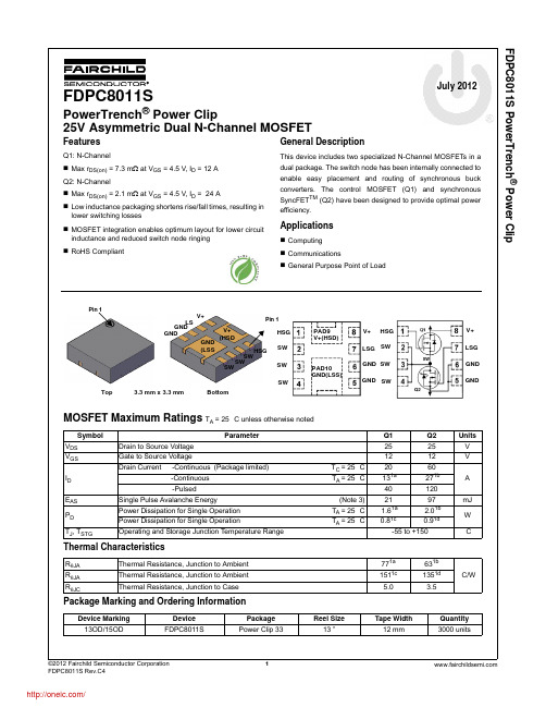
FDPC8011S PowerTrench ® Power ClipJuly 2012FDPC8011SPowerTrench ® Power Clip25V Asymmetric Dual N-Channel MOSFETFeaturesQ1: N-ChannelMax r DS(on) = 7.3 m Ω at V GS = 4.5 V, I D = 12 A Q2: N-ChannelMax r DS(on) = 2.1 m Ω at V GS = 4.5 V, I D = 24 ALow inductance packaging shortens rise/fall times, resulting in lower switching losses MOSFET integration enables optimum layout for lower circuit inductance and reduced switch node ringing RoHS CompliantGeneral DescriptionThis device includes two specialized N-Channel MOSFETs in a dual package. The switch node has been internally connected to enable easy placement and routing of synchronous buck converters. The control MOSFET (Q1) and synchronous SyncFET TM (Q2) have been designed to provide optimal power efficiency.ApplicationsComputing CommunicationsGeneral Purpose Point of LoadMOSFET Maximum Ratings T A = 25 °C unless otherwise notedThermal CharacteristicsPackage Marking and Ordering InformationSymbol ParameterQ1Q2Units V DS Drain to Source Voltage2525V V GS Gate to Source Voltage 1212V I D Drain Current -Continuous (Package limited) T C = 25 °C 2060 A -Continuous T A = 25 °C 131a271b -Pulsed40120 E AS Single Pulse Avalanche Energy (Note 3)2197mJ P D Power Dissipation for Single Operation T A = 25 °C 1.61a 2.01b W Power Dissipation for Single Operation T A = 25 °C 0.81c0.91dT J , T STGOperating and Storage Junction Temperature Range-55 to +150°CR θJA Thermal Resistance, Junction to Ambient 771a 631b °C/WR θJA Thermal Resistance, Junction to Ambient 1511c 1351d R θJCThermal Resistance, Junction to Case5.03.5Device Marking Device Package Reel Size Tape Width Quantity 13OD/15ODFDPC8011SPower Clip 3313 ”12 mm3000 unitsTop GND (LSSHSGSWSWSW Bottom3.3 mm x 3.3 mmPin 1HSG SWSW SWV+ (HSDV+LS GND GNDPin 1V+LSGGND GNDPAD9 V+(HSD)PAD10 GND(LSS)HSGSW SW SWSWV+LSG GND GND® Power ClipOn CharacteristicsDynamic CharacteristicsSwitching CharacteristicsForwardV GS = 12 V/-8 V, V DS = 0 VQ2±100nAV GS(th)Gate to Source Threshold Voltage V GS = V DS , I D = 250 μA V GS = V DS , I D = 1 mAQ1Q20.81.11.21.42.22.2VΔV GS(th) ΔT JGate to Source Threshold Voltage Temperature CoefficientI D = 250 μA, referenced to 25 °C I D = 10 mA, referenced to 25 °C Q1Q2 -4-3 mV/°C r DS(on)Drain to Source On Resistance V GS = 10 V, I D = 13 A V GS = 4.5 V, I D = 12 AV GS = 10 V, I D = 13 A,T J =125 °C Q14.65.45.66.07.37.3m ΩV GS = 10 V, I D = 27 A V GS = 4.5 V, I D = 24 AV GS = 10 V, I D = 27 A ,T J =125 °C Q2 1.21.41.7 1.82.12.4g FSForward Transconductance V DS = 5 V, I D = 13 A V DS = 5 V, I D = 27 AQ1Q297231SC iss Input Capacitance Q1:V DS = 13 V, V GS = 0 V, f = 1 MHZ Q2:V DS = 13 V, V GS = 0 V, f = 1 MHZQ1Q2 12404335pF C oss Output CapacitanceQ1Q2 3321126pF C rss Reverse Transfer Capacitance Q1Q249143pF R gGate ResistanceQ1Q20.40.5Ωt d(on)Turn-On Delay Time Q1:V DD = 13 V, I D = 13 A, R GEN = 6 ΩQ2:V DD = 13 V, I D = 27 A, R GEN = 6 ΩQ1Q2 713ns t r Rise TimeQ1Q2 25ns t d(off)Turn-Off Delay Time Q1Q2 2038ns t f Fall TimeQ1Q2 24ns Q g Total Gate Charge V GS = 0 V to 10 V Q1V DD = 13 V,I D = 13 AQ2V DD = 13 V, I D = 27 AQ1Q21964nC Q g Total Gate ChargeV GS = 0 V to 4.5 V Q1Q2930nC Q gs Gate to Source Gate Charge Q1Q2 2.69.3nC Q gdGate to Drain “Miller” ChargeQ1Q22.37.7nC® Power Clip1.R θJA is determined with the device mounted on a 1 in 2 pad 2 oz copper pad on a 1.5 x 1.5 in. board of FR-4 material. R θJC is guaranteed by design while R θCA is determined by the user's board design.2 Pulse Test: Pulse Width < 300 μs, Duty cycle < 2.0%.3. Q1 :E AS of 21 mJ is based on starting T J = 25 o C; N-ch: L = 1.2 mH, I AS = 6 A, V DD = 23 V, V GS = 10 V. 100% test at L= 0.1 mH, I AS = 14.5 A. Q2: E AS of 97 mJ is based on starting T J = 25 o C; N-ch: L = 0.6 mH, I AS = 18 A, V DD = 23 V, V GS = 10 V. 100% test at L= 0.1 mH, I AS = 32.9 A.a. 77 °C/W when mounted on a 1 in 2 pad of 2 oz copperc. 151 °C/W when mounted on a minimum pad of 2 oz copperb. 63 °C/W when mounted on a 1 in 2 pad of 2 oz copperd. 135 °C/W when mounted on a minimum pad of 2 oz copperGDF DS SF SS GDF DS SF SS GDF DS SF SS GDF DS SF SSPower ClipPower ClipPower ClipPower ClipPower ClipPower Clip分销商库存信息: FAIRCHILDFDPC8011S。
TRACER 5手持XRF分析仪产品介绍说明书

TRACER 5Portable XRF Analyzer for Cutting-Edge ResearchersHighlightsRh target X-ray source with interactive control of current and voltageLatest graphene window SDD technologySelectable measurement spot sizes (3 mm and 8 mm) Patented SharpBeam TM front end geometry for improved analysis precisionHelium purge capable5 position automatic filter changerManual filter / secondary target optionInternal sample camera for accurate measurement positioningIntegrated processor and data storageWi-Fi and USB connectivity to PCBruker Instrument Tools (BIT) PC softwarepackage enables instrument control,measurements, and communicationLive spectra directly on the TRACER 5 and on PCwith BIT and ARTAXARTAX PC software for comprehensive analysisincluding multiple spectra comparisons as well asBayesian inference and deconvolution modeling Bruker’s TRACER 5 handheld XRF analyzer provides unprecedented capabilities for sophisticated users. It synchronizes advanced technology with power, function, precision, and accuracy to providedynamic, field capable elemental analysisfrom everyday point-and-shoot testingto the complexities of cutting-edgematerials research. Elements as light asfluorine and sodium can be measured. The user can control current and voltage settings as well as utilize user changeable collimators and custom filters. The TRACER 5 enables scientists to visualize, identify, and analyze the relative elemental content of almost any substance on earth and beyond.Elemental Analysis from Fluorine to UraniumThe TRACER 5 handheld XRF spectrometer is based on the principle of energy dispersive X-ray fluorescence (XRF) for non-destructive elemental analysis of materials.Design and PerformanceThe TRACER 5 utilizes a high-performance graphene window silicon drift detector (SDD). It incorporates this latest detector technology with a 50 kV (4 W) rhodium end-window tube and SharpBeam™ front-end geometry providing maximum count rate and a scatter-minimized, clean spectrum. Combined with a helium beam path, it enables detection of elements lighter than any other handheld XRF analyzer on the market.Operator FriendlinessDesigned as both a “point and shoot” and“cutting-edge research” analyzer, the TRACER 5 requires minimal setup and operator training. Equipped with both user level and supervisor-level access, a manager can choose to grant basic operator control or full functionality. This two-tier approach and intuitive interface make the TRACER 5 perfect for both beginning users, as well as power users.The user interface has been designed to provide intuitive operation, including interactive control of measurement conditions. Results can be clearly viewed as composition, pass/fail, and live spectra. Data management and transfer are exceedingly easy to use via Wi-Fi or wired USB.Advanced Handheld XRF T echnologyUltimate FlexibilityThe TRACER 5 can be configured with factory ready calibrations which incorporate preset power, filter, collimator setting, beam path atmosphere, and measurement time. It also provides user control of all those settings for a fully lab-like instrument experience. Operators can select optimum excitation voltage and current settings, filter material, collimator spot size, and beam path atmosphere of air or helium. The TRACER 5 is designed with IP54 towithstand field operation in all environments, including humid and dusty conditions. TheTRACER 5 can be operated at wide temperature range of -10 °C to 50 °C (14 °F to 122 °F).The TRACER 5 incorporates an Easy Access™ rail mount to provide easy mounting for numerous accessories including a tripod, extension pole, soil foot, smartphone, andcollapsible desktop stand kit.TRACER 5 desktop stand kit with safety shield in placeTRACER 5 interactive user interface for control and resultsComprehensive FeaturesLatest Graphene WindowThe TRACER 5 incorporates a large area graphene window silicon drift detector (SDD). The graphene window replaces the traditional 8 μm beryllium window. This groundbreaking window is one of the first commercial usesfor graphene, an advanced material composed of atomic layers of carbon atoms arranged in hexagonal lattices.While the graphene is extremely thin, its unique structure makes it extremely strong. The graphene window has higher transmission of X-rays throughout the energy transmission for light elements such as fluorine, sodium, magnesium, silicon, and aluminum. The improved light element sensitivity enables lower detection limits and faster analysis. SharpBeam TM Optimized Geometry Every TRACER is precision built with Bruker’s patented SharpBeam TM Optimized Geometry including benefits, such as:produces a sharp, defined measurementspotimproves measurement precisionreduces power requirementsreduces stray scatterincreases battery lifereduced instrument er Changeable Collimators and Custom FiltersThe TRACER 5 is designed with a portal to enable manual use of changeable collimators and filters. A TRACER 5 is supplied with two collimators, one which generates an 8 mmoval spot and one a 3 mm oval spot. Use of the 3 mm collimator provides a measurement area for the isolation of a small feature to be tested. The larger 8 mm spot size is preferable for inhomogeneous materials and bulk samples.In addition to its 5-position filter wheel with industry-standard handheld XRF filters for preset factory calibrations, the TRACER 5 also enables use of custom filters for unique sample analysis. To adapt custom filter materials, various manualfilter accessories are available.Portal for user changeable collimators (3 mm bottom leftand 8 mm bottom right) and custom filtersAir is the standard atmosphere for measuring heavy metals in multiple matrices, heavy elements (Ti to U) in multiple matrices, and light elements (Mg to Zn) in heavy metal alloy matrices.To get the best signal for light elements, air needs to be removed between the sample and detector. This can be accomplished by purging with helium through a port connection (seebelow) that significantly improves measurements for very light elements (F to P) in multiple matrices.ARTAX PC SoftwareThe ARTAX PC software provides the ability to visualize, identify, and analyze the relative elemental content of almost any substance. This easy-to-use spectral analysis software enables the determination of how elements interact within their sample set. It provides a project management data base which can contain hundreds of thousands of spectra and can be organized in a logical structure for a given ers can apply their own subject matterexpertise to guide analysis while the software applies advanced mathematics involved in Bayesian analysis of the spectra. Outputs from ARTAX software are in Excel format, so they can be imported into any of the analysis programs already in use.Integrated CameraThe TRACER 5 is equipped with an internal CMOS camera to provide sample visualization and precise alignment of the target sample area using an oval spot or a reticle projected onto the sample image. Up to five images can be stored with each spectrum for later identification of the sample area analyzed.camera features ensure accurate measurementpositioning, even for very small 3 mm spots up to five images per assay can be saved to provide visual measurement recordsimages can be easily imported into reportsSelectable Beam Path – Air or HeliumAtmosphere will impact the results obtained in an XRF measurement, especially for light elements like F, Na, Mg, Al, Si, and P. Anymaterial between the sample and detector will absorb some of the low-energy X-rays emitted by the sample before they arrive at the detectorto be counted.Integrated camera for targetting sample areasPort connection (red circle) to purge with heliumApplications and Calibrations Bruker’s TRACER 5 handheld XRF analyzerwith its advanced and unique features andsoftware enables elemental analysis of almostany substance. It can be used for in-situmeasurements and set up in a desk top stand forsmall or prepared samples. It can be configuredwith both unique and common factory pre-loadedcalibrations which provide results as identifiedmetals and alloys, elemental composition,or pass/fail. The TRACER 5 also enablescomprehensive compositional and spectralanalysis for specialized applications including:Archaeological StudiesThe TRACER 5 not only helps investigatehomogenous samples, but also complex,heterogeneous, and non-uniform samples.This is especially important for archaeologicalresearch to identify, compare, and quantifyelements of sample materials in the context oftheir environment. The TRACER 5 helps provideimmediate information for dynamic scientificinsight into found objects, artifacts, and theirsurroundings including ceramic, bone, obsidian,glass, metal, and soil.Art Conservation and AuthenticationThe Bruker TRACER 5 handheld-XRF is thebenchmark portable analytical solution forcultural heritage elemental analysis used byexperts the world over in laboratories, galleries,and on-site locations. It’s an essential tool formeeting multiple objectives in the analysis offine art, architecture, objects, adornments,sculpture, and more:Research and interpretationDetermine of original materialsAuthentication of origin or contextGuidance for conservation and restorationSemiconductor ManufacturingThe TRACER 5 enables measurements offluorine compounds which are used for a varietyof semiconductor manufacturing applicationsincluding chemical vapor deposition, plasmaetching, and cleaning.Natural Resource InvestigationsThe TRACER 5 provides comprehensive field portable solutions for natural resource research. It helps to measure and map majors, minors, and target elements of ores, cores, drill cuttings, soil, and sediment:Chemostratigraphy and quantitative characterization of geologic samplesCompositional oceanographic studies for exploration, utilization, and preservationEnvironmental assessments for heavy metals, mineral nutrients, and sodicity in soils and plantsMaterials Research and EducationThe TRACER 5 flexibility to analyze both uniform and non-uniform materials with and without standard reference samples makes it a perfect choice for both research and teaching. The TRACER 5 helps provide students experiential, value-driven science with near-instant feedback to engage them in the classroom, on field trips with real-world samples, and even in the lab.Factory User-Ready CalibrationsA wide range of unique and common factory calibration options is available for the TRACER 5. These calibrations can be customized to perfectly fit specific requirements. Customers can also create and modify their own custom empirical calibrations with Bruker’s EasyCal PC software.TRACER 5 common calibration examples are:Alloys and MetalsPrecious MetalsHeavy Metals and Nutrients in Soil; PlantsGeoExploration; LimestoneConsumer Safety Restricted Materials TRACER 5 unique calibration examples are:Ancient Copper AlloysCustomized CeramicsGlassMudrockObsidianDrill core analysisAnalysis of obsidianPC software with measurement setting control, drop down menu of preloaded calibrations, and data processing options.Technical SpecificationsBruker Nano AnalyticsHeadquarters Berlin · Germany Phone +49 (30) 670990-0 Fax +49 (30) 670990-30 *******************/tracerA l l c o n f i g u r a t i o n s a n d s p e c i f i c a t i o n s a r e s u b j e c t t o c h a n g e w i t h o u t n o t i c e .© 2022 B r u k e r N a n o G m b H , A m S t u d i o 2D , 12489 B e r l i n , G e r m a n y . O r d e r N o .D O C -B 83-E X S 003.。
功放说明书-daprex-dap-8000_c-dap-5000_c.pdf

专业功率放大器DAP-8000/DAP-5000使 用 说 明 书非常感谢您惠购我们的专业功率放大器。
使用前,请务必逐页详阅本说明书,以便充分利用本设备。
使用本设备遭遇任何问题或麻烦时,查阅本说明书可为您提供及时帮助。
请始终遵循以下指示请勿擅自拆开或改装请勿打开(或以任何方式改装)设备或其电源线。
一个三角形图形里边有一个闪电形的箭头表明,警告设备里面有未绝缘的足够让人触电的危险电压存在。
图形解释请勿擅自修理或更换部件请勿尝试修理本设备,或者更换其内部的部件(除非本使用说明书有特别说明指导您这么做)。
所有维修服务请咨询您的经销商。
请勿在以下位置使用或存储温度过高的场所(例如:阳光直射的封闭车厢内、加热管附近、发热设备上方),靠近水源的场所(例如:浴室、盥洗室、潮湿地面),暴露在水汽或烟雾之下的场所,空气中含盐份较高的场所,潮湿的场所,直接遭受雨淋的场所,灰尘较多的场所,震动剧烈的场所。
靠近厨具因而可能接触烟,油,热的地方。
请勿放置在不稳定的位置确保始终水平放置本设备并保持平稳。
请勿将其放置在容易晃动的支架或斜面上。
仅使用随附的电源线仅使用附带的电源线。
此外,随附的电源线不能与任何其他装置起使用。
请勿弯曲电源线或在其上放置重物请勿过分缠绕或弯曲电源线,也不要在其上放置重物。
这样做可能会损坏电源线,从而造成电源线断裂和短路。
电源线损坏可能会引发火灾和触电事故!避免在高音量时扩展使用本设备配合扬声器起使用所产生的声级有可能会造成永久性的听力丧失。
请勿长时间在超高音量级别(或让人不适的音量级别)下操作本设备。
如果您感到听力损失或耳鸣,应立即停止使用本设备并迅速求诊。
一个闪电形的箭头表明,警告设备里面有为绝缘的危险电压存在,该电压将足够让人有电击的危险。
一个三角形图形里边有一个惊叹号表明,警告附在设备上的印刷品上有重要操作和维修指导(服务)。
防止火灾、电击和人身伤害的说明不要让异物或液体进入设备;绝不要将装有液体的容器放在设备上请勿在本品上放置装有液体的容器。
FD100说明书
四. 按键说明
1. “设定”键:按此键,仪器进入设定状态,此后可修改开关次数、通电时 间、断电时间三参数。
2. “ ”键:当仪器处在设定状态时,此键才有效,按此键可使“可修改位” 循环移动。
3. “△”键:当仪器处在设定状态时,此键才有效,按此键可使“可修改位” 的数据依次从 0~9 变化。
伏达仪器
_____________________________________________________________________________
FD100 寿命试验仪
使
用
手
册
——————————————————————
杭州伏达测试技术研究所
地址:杭州市益乐路 223 号银江科技园 A 幢 3 楼 电话:0571—8858219 88910474 邮编:310012
4. “启动”键:连续按三下此键。仪器从 0 开始重新工作,在仪器开始工作 后,一般不要按此键。
5. “显示”键:按此键,显示窗口循环切换显示时间和次数。 6. “消音”键:当试验次数到达设置的要求次数后,仪器声光报警,此时按
此键,可解除声报警。 7. “复位”键:按此键,相当于仪器软启动一次。
五. 设定操作说明
一. 功能
本仪器专门为电子镇流器、节能灯耐久性(寿命)试验而设计,具有以下 功能:
1.内置单片微机,实现智能控制。 2.开关次数、通电时间、断电时间均可按需要自由设置。 3.试验完毕,声光报警。 4.停电自动保存数据,来电继续工作。 5.内部用无触点固态继电器,寿命长、无噪声。
二. 主要技术指标
1. 开关次数设置范围:1~100 万次。 2. 通电、断电时间设置范围:1 秒~99 小时 59 分 59 秒。 3. 内用无触点固态继电器,寿命长、无噪声。 4. 内部继电器容量:250V/30A。
诺瓦科技LED交通多媒体播放器JT100规格书

6.1 图片 ........................................................................................................................................................... 10 6.1.1 解码器 .................................................................................................................................................... 10 6.1.2 编码器 .................................................................................................................................................... 10 6.2 音频 ........................................................................................................................................................... 11 6.2.1 解码器 .................................................................................................................................................... 11 6.2.2 编码器 .................................................................................................................................................... 11 6.3 视频 ........................................................................................................................................................... 12 6.3.1 解码器 .................................................................................................................................................... 12 6.3.2 编码器 .................................................................................................................................................... 13
- 1、下载文档前请自行甄别文档内容的完整性,平台不提供额外的编辑、内容补充、找答案等附加服务。
- 2、"仅部分预览"的文档,不可在线预览部分如存在完整性等问题,可反馈申请退款(可完整预览的文档不适用该条件!)。
- 3、如文档侵犯您的权益,请联系客服反馈,我们会尽快为您处理(人工客服工作时间:9:00-18:30)。
Jul. 2004
TYPE NAME 12 ± 2
26 ± 0.5
0.4MIN
φ85 ± 0.2 φ120MAX φ3.5 ± 0.2 2.2 ± 0.2DEPTH
¡VRRM Repetitive peak reverse voltage ................... 5000V ¡IF(AV) Average forward current ..................... 5000A
10.5 ± 1
Jul. 2004
元器件交易网
MITSUBISHI RECTIFIER DIODE
on. ange. ificati h l spec bject to c a fina su is not limits are is e: Th metric Notice para Som
元器件交易网
MITSUBISHI RECTIFIER DIODE
on. ange. ificati h l spec bject to c a fina su is not limits are is e: Th metric Notice para Som
Pቤተ መጻሕፍቲ ባይዱ
MIN RELI
(Recommended value 47kN) Typical value 1450g
ELECTRICAL CHARACTERISTICS
Symbol VFM IRRM Rth(j-f) Parameter Forward voltage Repetitive peak reverse current Thermal resistance Test conditions IFM = 7000A, Tj = 150°C VRM = 5000V, Tj = 150°C Junction to Fin Min. — — — Limits Typ. — — — Max. 1.6 200 0.0071 Unit V mA K/W
P
MIN RELI
ARY
FD5000AV-100DA
HIGH-POWER, GENERAL USE PRESS PACK TYPE
PERFORMANCE CURVES
MAXIMUM THERMAL IMPEDANCE CHARACTERISTIC (JUNCTION TO FIN) MAXIMUM ON STATE CHARACTERISTIC 105 100 2 3 5 7 101 0.010 0.009 104
APPLICATION High-power inverters Fly-hweel diode for GCT Thyristor Power supplies as high frequency rectifiers
MAXIMUM RATINGS
Symbol VRRM VRSM VR(DC) Symbol IF(RMS) IF(AV) IFSM I2t Tj Tstg — — Parameter Repetitive peak reverse voltage Non-repetitive peak reverse voltage DC reverse voltage Parameter RMS forward current Average forward current Surge forward current Current-squared, time integration Operation junction temperature Storage temperature Mounting force required Weight Conditions — — — Conditions Applied for all condition angles f = 60Hz, sinewave θ = 180°, Tf =70°C One half cycle at 60Hz, Tj =150°C start Voltage class 5000 5000 2000 Ratings 7850 5000 70 2.0× 10⁷ –40 ~ 150 –40 ~ 150 39 ~ 55 — Unit V V V Unit A A kA A2s °C °C kN g
ARY
FD5000AV-100DA
HIGH-POWER, GENERAL USE PRESS PACK TYPE
FD5000AV-100DA
OUTLINE DRAWING
Dimensions in mm
6.35 × 10.8 φ3.5 ± 0.2 2.2 ± 0.2DEPTH 0.4MIN φ85 ± 0.2
Zth (K/ W)
0.008 0.007 0.006 0.005 0.004 0.003
IF (A)
103
Tj=150°C Tj=25°C
102
0.002 0.001
101
0
0.5
1 VFM (V)
1.5
2
0.000 10-3 2 3 5 7 10-2 2 3 5 7 10-1 2 3 5 7 100 TIME (S)
