吊车专业文档SystemReset-Mipeg2000Recording
吊车性能手册

起重机吊装手册目录页页1、起重机吊装规定12、日本NK-8A型液压式汽车吊93、日本NK-160型液压式汽车吊104、日本TL-252型液压式汽车吊115、日本NK-300型液压式汽车吊126、日本NK-360型液压式汽车吊147、日本NK-400型液压式汽车吊158、国产QY-50A型液压式汽车吊189、日本NK-600吨液压式汽车吊1910、日本NK-750型液压式汽车吊2111、日本TG-752型液压式汽车吊2212、日本NK-800型液压式汽车吊2413、德国100t液压式汽车吊2614、日本NK-1200型液压式汽车吊2915、日本NK-1600型液压式汽车吊起重机吊装规定1 总则为了提高施工技术水平,加强技术管理,确保设备、结构吊装工程安全,特制定本规定:大型设备的吊装工程,除应遵守本规定外,尚应遵守国家有关技术政策及现行有关标准规范的规定。
2 适用范围及引用标准2.1 适用范围本规定适用于石油化工装置检修工程,采作履带起重机、轮胎起重机和汽车起重机为起重机械的设备或结构吊装。
2.2 引用标准2.2.1 建筑机械使用安全技术规程JGJ33-20012.2.2 石油化工施工安全技术规程(SH3505-1999)2.2.3 起重机械安全规程(GB6067-85)2.2.4 起重吊装指挥信号(GB5082-85)2.2.5 大型设备吊装工程施工工艺标准(SHJ515-90)起重工安全技术操作规程设备吊装作业指导书结构吊装作业指导书3 吊车吊装规定3.1 设备吊装计算载荷应小于吊车额定起重能力。
3.2 吊臂与设备及吊钩滑车三者间应有足够的安全净距。
3.3输电线路与设备和起重机具间的最小间距应符合下表规定4 吊车选择4.1 吊车选择依据a、设备结构尺寸、重量、安装高度、重心位置和强度、刚度及稳定性。
b、吊装环境c、技术装备能力d、施工人员技术素质e、安全技术要求f、经济效益4.2 吊车吊装技术性能参数选择a、额定起重能力b、吊臂长度c、工作半径d、回转速度e、吊臂负载作业回转限界f、吊装工艺计算所需的技术参数4.3主吊车选择程序a、确定设备主辅吊点位置b、初选吊车车型c、初拟吊车位置d、计算吊臂理论状态参数(杆长、幅度)e、初选吊臂实际状态参数f、计算吊臂与设备及吊钩滑车间的净距4.4 主吊车的最终选择a、单机吊装计算载荷应小于额定起重量。
履带吊单机档案
配件有件,于年月日更换使用。
配件有件,于年月日更换使用。
配件有件,于年月日更换使用。
配件有件,于年月日更换使用。
配件有件,于年月日更换使用。
配件有件,于年月日更换使用。
配件有件,于年月日更换使用。
配件有件,于年月日更换使用。
配件有件,于年月日更换使用。
配件有件,于年月日更换使用。
时间:
维点
人员:
所更
换的
主要
零部
件:
过
程
简
要
记
录
七、安全操作注意事项
a)基本操作注意事项
b)本要特别注意事项
八、事故记录
九、操作人员管理记录
操作人员动态管理表
序号
姓名
性别
年龄
上岗时间
离岗时间
培训记录
操作证取证时间
发证机关
有效效期至
备注
十、随机技术资料、所附配件工具记录
a)技术资料
(1)份
其中份留存于上级部门,份留存于本公司资料室,份留存于司机。
(17)份
其中份留存于上级部门,份留存于本公司资料室,份留存于司机。
b)所附工器具记录、配件记录
工器具有:
(2)配件有件,于年月日更换使用。
配件有件,于年月日更换使用。
配件有件,于年月日更换使用。
配件有件,于年月日更换使用。
配件有件,于年月日更换使用。
配件有件,于年月日更换使用。
配件有件,于年月日更换使用。
2.年度油耗记录
3.配件消耗记录(1000元以上的配件)
一、
设备概述
机械名称:
规格型号:
制造厂家:
Demag 过程吊车组件说明书

40899-138956-138546-8Frequency invertersMPW crabsMPW open winch unitsBottom blocks40172837-240555-8-140616-140986@d a v i d j o n e s o n T w i t t e rurope s largest video module in a multi-purpose arena in stanbul – safely held by two MPW open winch unitsBenefits of MPW open winch units:■True vertical lift reeving arrangements from to ■ ompact dimensionseduced drum lengths thanks to rope end attachment to side flanges ■ ptimised rope drum■Minimum drum wear thanks to enlarged rope groove opening angle■ ong rope service life – also under arduous conditions – thanks to plastic filling between the strands■ ptimum crane approach dimensions in combination with high lifting performance large drum diameters and small crab track gauges can be achieved thanks to hoist gearboxes with a large shaft centre distance ■ afe operation thanks to an optional second hoist brake ■ lear interfaces for ease of assembly and maintenance ■Minimum maintenance requirement and easy to service ■ hort installation times thanks to pre-assembled solutionsandling equipment for storing long materialthe lifting motions are provided by MPW open winch units5-65483 52-54993725-292-240969-440893409404Power and precision emag drives to meet the most de manding quality requirements. pace-saving combination of emag angular geared motor and W wheel set39339-140970-5quirements. n the basis of standardised sub-assemblies, we develop and supply you with pre-assembled modulesnverter systems for drive solutions tailored to meet your needs emag travel units equipped with perfectly matching system components40683-440192-64098740683-3Fully pre-assembled MPW crabwith a telescoping gripper for handling toolsPerfectly prepared -tonne MPW open winch units MPW open winch unit employedin a gripper system for transporting steel slabssales_mhe@Printed on recycled paper0418 E N /M H E 213 706 44 M H E 701 I S 110N o l i a b i l i t y f o r e r r o r s o r o m i s s i o n s . S u b j e c t t o c h a n g e .OVER70 SALES &SERVICE OFFICES ACROSS THE ASIA-PACIFICTAIWAN+886 7 970 8900PHILIPPINES +63 2 786 7500PAPUA NEW GUINEA +675 3112442VIETNAM+84 283 8236 540CAMBODIA+855 23 992 610THAILAND +66 2 7878 500AUSTRALIA+61 1300 336 241INDONESIA +62 21 2753 7200MALAYSIA +60 3 3345 7888SINGAPORE +65 6305 3500。
2000型岸边集装箱起重机说明书DOC
2000型岸边集装箱起重机使用说明书编制:校对:审核:上海**重工有限公司目录一、概述1. 产品特点2. 主要技术性能3. 设计制造标准4. 起重机工作级别5. 使用环境条件二、结构特征与工作原理1. 金属结构2. 主小车3. 起升机构及钢丝绳缠绕系统4. 小车运行机构5. 大梁俯仰机构、钢线绳缠绕系统及安全钩6. 大车行走机构7. 倾转装置8. 电缆拖令系统及电缆卷筒装置9. 吊具及吊具上架装置10. 司机室及机器房11. 电梯12. 机器房维修行车13. 液压系统三、安全注意事项1. 起重机运转前的准备事项2. 作业后的注意事项3. 防风防台注意事项4. 码头轨道基础一、概述本起重机是上海**重工有限公司专为巴拿马型集装箱船作业的需要而设计制造的轻型岸边集装箱起重机。
1. 产品特点:本起重机是集装箱码头前沿装卸集装箱船舶的专用起重机,可沿与岸线平行的轨道移动。
海侧前伸臂在船舶靠岸、离岸及转换工作泊位与不工作时可以仰起,以免碰撞船舶的上层建筑。
本机吊具下的额定起重能力为35吨,最大前伸距为28米,配套20’,40’的集装箱单箱吊具,同时配有吊钩横梁换下吊具换上吊钩横梁后可起吊50吨重的货物。
特殊情况下通过吊具上架的四只吊耳,可起吊48吨重的货物。
本机的上机电源为交流三相10KV10%,50Hz1Hz。
供电方式为将设在码头海侧地面供电坑中的输出的电源,通过装在海侧门框上的高压电缆及电缆卷筒,然后供电给起重机,高压电源经高压进线柜、开关柜、高压变压器、配电柜来驱动各主要工作机构及辅助机构。
本机采用交流变频电控系统,有先进的电气调速、控制性能,可实行故障诊断显示。
本机的前大梁采用三角形管桁架结构,后大梁采用梯形板梁结构,小车轨道布置在梁的外侧。
海陆侧门框、梯形架采用矩形梁结构,斜撑杆为螺旋管结构,前大梁的拉杆为“H”型结构,后大梁与海陆侧门框均为刚性连接,整机钢结构具有足够的强度与刚度。
小车轨道采用QU80轨道,特殊的铰点结构及轨道接头型式,使高速、重载小车能平稳运行。
起重机(提升机)静态和动态性能分析计算书.
装卸桥静态和动态性能分析计算报告1、技术目标:对甲方提供的A7型10t装卸桥利用大型有限元分析软件ANSYS建立有限元计算模型,并对其进行有限元分析。
2、分析内容:分析计算的内容如下:(1)计算工况为:跨中、左1/4跨、左极限位置、右1/4跨、右极限位置。
计算载荷为:风载荷、额定载荷、1.25倍载荷;(2)分析计算装卸桥主梁和支腿的位移、应力、应变,以及装卸桥的最大应力和最大变形位置;(3)分析计算装卸桥主梁、刚性支腿和柔性支腿的自由模态频率和阵型,以及满载小车位于右侧行程极限时,装卸桥的模态频率和阵型;(4)分析计算装卸桥的稳定性;(5)校核装卸桥关键连接面的连接螺栓强度。
该装卸桥的主要性能参数为:额定载荷10t;跨度50m;材料全部采用Q235。
3、静力分析计算3.1有限元模型分析过程采用商业有限元软件ANSYS10.0。
首先研究装卸桥的结构参数、材料性能、工况,以及零件的尺寸和结构形式;然后根据装卸桥的结构特性和合同内容要求,分析ANSYS10.0单元库的单元类型,选择合适的单元来建立有限元模型。
装卸桥的零件比较多,如果采用的单元类型过多,划分网格的时候,由于不同形状单元之间过渡,容易引起单元畸形,影响最终的分析精度。
因为装卸桥的零件主要是板型和梁型,所以在装卸桥有限元分析的过程中,主要采用了SHELL63单元和BEAM188单元。
装卸桥板型零件采用SHELL63单元。
SHELL63是一种4节点线弹性单元,它遵循基尔霍夫假定,即变形前垂直中面的法线变形后仍垂直于中面,SHELL63既具有弯曲能力,又具有膜力,可以承受平面内荷载和法向荷载。
本单元每个节点具有6个自由度:沿节点坐标系x、y、z方向的平动和沿节点坐标系x、y、z轴的转动。
应力刚化和大变形能力已经考虑在其中。
比较符合装卸桥板型零件的实际受载情况。
梁型零件采用BEAM188单元。
BEAM188单元是一个三维线性(2节点)有限应力梁,当Keyopt(1)=0时,每个节点6个自由度。
维修和保养一位100 20吨EOT吊车的说明书

For Publishing in NewspaperUJVN LTD.248006Website:CorrigendumThe technical specifications of Section-4 of Tender No:CH(Maint.)-07/2016-17, invited by this office, for “Repairing andoverhauling of 100/20 Ton EOT crane No.-1 at Chibro PowerStation”, have been revised and uploaded on Nigam website:‘’.Submission & opening dates of the tender and remaining allother conditions shall remain unaltered.(Executive Engineer, Maint., Chibro)___________________________________________________________________________t o h,u fyfeVs Meq[M]g jknw u&248006nw j D l& 0135&2763508lh0vkbZ0,u0 la0os c lkbV % ”kq f) i=bl dk;kZ y; ds}kjk vkea f=r fufonk la0& Lkh0,p0¼vuq0½&07@2016&17 %fNcjks fo/kq r xz g ij 100@20 Vu bZ0vks0Vh0dz u ua0&1 dh ejEer ,oa vks o jgkW f ya x dk dk;Z A ds Section - 4,Technical Specification dks iq u f jf{kr fd;k x;k gS] ftldk foLr`rfooj.k fuxe oS c lkbZ V ij miyC/k gS Afufonk tek ,oa[kks y us dh frfFk;ka rFkk vU; ”krs;Fkkor~jgs x hAvf/k”kklh vfHk;Urk ¼vuq½] fNcjks“fctyh ds nq:i;ks x ls cps”SECTION-4: REVISED TECHNICAL SPECIFICATIONSTender No. – CH(MAINT.) - 07/2016-17Name of Work: Repairing and overhauling of 100/20 Ton EOT Crane-I of Chibro Power Station.General :The Chibro Power Station is an underground Power Station with 240 MW installed capacity and located around 70 Kms from Dehradun. Chibro Power Station was constructed under Yamuna Stage- II Scheme which commissioned in 1975.SCOPE OF WORK :SNo. Description of Work Unit QtyJob 11 Repair and overhauling of 100 Ton bottom block pulley assemblywith hook:-dismantling & cleaning of bottom assembly includingremoval of ropes, trunion, load hook, side and middle pulley guards,middle spacer, rope pulleys, bearings of pulleys, pulley pin, hook nut,single thrust ball bearing, load hook etc., Inspection of all parts ,repair and replacement of damaged and missing parts like pulleys,bearing spacers, grease nipples, pulley pins, trunion, nut & bolts etc.including replacement of oil seals, o rings, gaskets and cleaning ofgrease line by removal of old grease and filling of fresh grease andfilling of bottom block pulley assembly with hook and revving ropes,their setting, adjustment and alignment and testing includingbalancing of hook. bearing no.(SKF 29334) 1 no as per instructionmanual if found defective shall be replaced, 8 no. pulleys shall beoverhaulled equalizer pulley also.& repaired if bearing 22222C asper manual found defective shall be replaced.Job 12 Repair and overhauling of 20Ton bottom block pulley assemblywith hook:- dismantling & cleaning of bottom assembly includingremoval of ropes, trunion, load hook, side and middle pulley guards,middle spacer, rope pulleys, bearings of pulleys, pulley pin, hooknut, single thrust ball bearing, load hook etc, Inspection of all parts ,repair and replacement of damaged and missing parts like pulleys,bearing spacers, grease nipples, pulley pins, trunion, nut & bolts etc.including replacement of oil seals, o rings, gaskets and cleaning ofgrease line by removal of old grease and filling of fresh grease andfilling of bottom block pulley assembly with hook and revving ropes,their setting, adjustment and alignment and testing includingbalancing of hook. bearing no.(SKF 030) 1 no. as per drawing founddefective shall be replaced , overhauling of 6 no. pulleys 380mm. andequalizer pulley also.Job 13 Repair & overhauling of Gear box of MH Ratio 56:1 size 970DTLW check the bearing, gear profile after emptying the gear oil &replace the gear box seal, gaskets etc.Job 14 Repair & overhauling of Gear boxes of AH Ratio 80:1 size 770DTLW check bearings, gear profile after emptying the oil & replacegear box oil seal, gaskets etc.Job 15 Repair & overhauling of Gear box of CT 25.8:1,type H.D.5 checkthe bearings, gear profile after emptying the oil & replace gear box oilseal, gear oil, gaskets etc.6 Repair & overhauling of LT speed reducer 11:1 ratio, DS 415 sizeJob 1 vertical type check the bearings, gear profile after emptying the oil &replace gear box oil seal, gear oil, gaskets etc.7 Repair & overhauling of all the plummer blocks . Job 18 Repair & overhauling of all the brake system assembly inclusive ofJob 1 brake control panel of LT, CT, MH, AH by providing all requiredelectrical items such as contractors, transformers etc. with allmeasures.a) Replacement of Brake liner and aluminum rivets. Repair ofelectromagnetic brake and all adjustment for brake setting.Job 1 9 Overhauling and repair of wire ropes drums of MH and AH andrelated works:-dismantling, cleaning of main and auxiliary hookshoists wire rope drums and related parts and gear assembly bycomplete unwinding of the ropes, inspection of all parts includingdetail inspection of ropes & replacement of missing, damaged andworn out parts like pinions, shafts, gears, pulleys, grease nipples,pins, support of pin pinion pedestal, rope clamps, gear covers, gerrings, rope drums, output shafts, limit switches, split spring bushchains, nut & bolts etc including replacement of oil seals, O rings,gaskets and cleaning of grease line by removal of old grease andfilling of fresh grease and reassembly and fitting of drums, setting andadjustment of wire rope drums including unrolling and cleaning andwashing of rope for removal of old compound, dust dirt etc rewindingof ropes after cleaning, measurement of rope dia, inspection of wirerope strands application of cardmium compound and rolling of therope on aux and MH drums, testing for satisfactory operation. ropedrum of main hoist dia.-900 mm. and auxiliary hoist rope drum dia.-500mm. Supply and fixing of counter weight limit switches (Make-Crane control equipment or equivalent) for MH and AH.Job 1 10 Repairing/Modification of all the couplings, keys , keyways bywelding, grinding with all other means & replace defective andmissing bolt nuts, rubber bushes.Job 1 11 Inspection and repair of wheel Assembly of LT and CT:-Dismantling and cleaning of wheel assembly with removal of wheelbearings etc, inspection of wheel assembly parts like wheels, wheelbearings, bearing greases line etc, repair and replacement of damagedand missing parts like bearings, keys, gears etc reassembly of wheelsincluding replacement of oil seals, o rings, gaskets including cleaningof grease line by removal of old grease and filling of fresh grease andfitting of wheels their setting adjustment and alignment. Bearinggrease shall be provided by the contractor. Supply and fixing of levertype limit switches (Make- Crane control equipment or equivalent)12 Repair & overhauling of complete electrical system of craneJob 1 12.1 Repair & overhauling of all the motors (slip ring) MH-40HP, AH-30HP, LT-25HP, CT-11HP.Dismantling, cleaning and inspection of all motor parts, like rotor,stator winding, bearings, cooling fans ring assembly etc varnishingof all motors windings, IR testing of all motors, damaged slip ringassembly, balancing of rotor, checking and tightening of motormounting and fixing bolts, alignment of motors with final assembly,fitting and testing of assembled equipment.Job 1 12.2 Repair and overhauling of resistance box:-Dismantling andcleaning of all resistance boxes, checking of all insulators, insulatorsbetween grids and earth replacement of damaged resistancepunching, mica tubes, mica washers, connections, fixations, wirewound balancing resistances with final assembly, fitting and testingof assembly equipment. Supply and fixing of chequered plates underresistance boxes for safety purpose.Job 112.3 Replacement, realignment and dressing of all power and controlcables and repair of all panel cabinets:-Physical inspection ofcables, IR testing of cables, removal and replacement of damagedcables, dressing of all existing cables, tightening of all cableterminations in panels and switchgear with final assembly includingwith provision of all safety measures such as remote and tandemcontrol system etc.. EOT crane No.-2 shall be tested in tandemthrough EOT crane-1. For this, all required comprehensive measuresshall be deemed in the scope of contractor. Strengthening of panelcabinet by providing and welding of angles in this way that panelshould not vibrate while crane’s movement.12.4 Installation of Thruster brakes assembly on LT, CT and Aux. hoist,Job 1 LT master controller& installation of LED lights after dismantle theold material.12.5 Installation of another thruster bake assembly on AH system:Installation of another brake drum and thruster brake on 50 mmshaft diameter on Aux. hook by modification or by other means inpresent system13 Supply ItemsNo. 113.1 34 Kg thruster brake make Stromag/powermech or equivalent forLT Brake system drum Dia.-300mmNo. 113.2 18Kg thruster brake make Stromag/powermech or equivalent for AHBrake system drum Dia.-300mmSet 113.3 90 watt 2 No. LED lights open type vertical high bays of Havellsmake or equivalent for EOT crane an 1 No. 18 watt LED of Havellsor equivalent for operator’s cabinNo. 213.4 Master controller for Aux. hoist and CT (Make crane controlequipment or equivalent).13.5 19 core 2.5 Sq.mm cable ISI mark for control circuit Mtr. 100 13.6 Brake drum coupling diameter 300 mm of forged steel material forNo. 1 another brake of AH(Make crane control equipment or equivalent).Any other work which is not mentioned but required for successful completion of above scope, shall be deemed in the scope of contractor.Executive Engineer (Maint.)Chibro Power Station。
港机吊车 说明
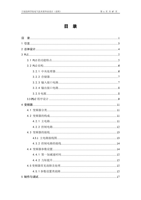
目录目录 (1)1 引言 (3)2 总体设计 (4)3 PLC (5)3.1 PLC的功能特点 (5)3.2 PLC结构 (6)3.2.1 中央处理器 (6)3.2.2 存储器 (7)3.2.3 输入接口电路 (7)3.2.4 输出接口电路 (8)3.2.5电源 (8)3.3 PLC程序设计 (9)4 变频器 (11)4.1 变频器分类 (11)4.2 变频器的构成 (11)4.2.1 主电路 (11)4.2.2 控制电路 (12)4.3 变频器的接线 (13)4.3.1 主电路接线图 (13)4.3.2 控制电路的接线 (14)4.4 变频器参数设置 (14)4.4.1 第一加减速时间 (15)4.4.2 力矩提升 (15)4.5变频器常见故障及处理 (15)4.5.1参数设置类故障 (15)5 制作与调试 (17)5.1 设备安装 (17)5.2 操作运行 (17)5.3 调试 (18)5.3.1 硬件调试 (18)5.3.2 软件调试 (18)5.3.3 程序跟继电器联合调试 (25)5.3.4 变频器的调试 (27)6 故障点说明 (29)参考文献 (35)附录1 原理图 (36)附录2 元件清单 (42)附录3 I/O分配表 (43)附录4 PLC程序 (46)附录5 实物照片 (56)1 引言随着港口的发展,在港口中越来越多的吊车受到港口码头的使用,吊车的种类也越来越多。
而港机吊车因为它的小巧,使用方便,越来越受到港口的生产使用。
本设计是根据实际生产需求,设计一款港机吊车。
完成港机吊车的一些基本功能,例如:大车的前进或后退,吊臂的左转或右转,吊臂前后位置的调整,料斗的上升或下降,料斗的抓斗或松开等。
使用现在工控先进设备中的PLC、变频器等设备。
-128MR型号,变频器为松下通用型本次设计主要使用的PLC为三菱FX2NFR-D700系列变频器,以及其他一些电气元气件。
2 总体设计本次课题主要以PLC为核心,变频器实现无极调速。
(完整word)Q2-8汽车起重机液压系统资料
目录摘要 (1)第1章绪论 (2)1。
1国内轮式起重机发展现状 (2)1。
2国外轮式起重机发展过程及主要机种 (3)1.3轮式起重机产品的发展趋势 (4)1.4主要工作 (5)第2章起重机技术参数的确定 (6)2.1主要性能参数 (6)2。
2Q2—8型汽车起重机参数确定 (6)第3章各液压回路组成原理和性能分析 (8)3.1支腿液压缸收放回路 (8)3。
2回转机构液压回路 (10)3.3伸缩机构液压回路 (11)3。
4变幅机构液压回路 (12)3。
5起升机构液压回路 (13)3。
6液压系统的特点 (15)3.7汽车起重机液压系统总成 (15)第4章液压系统计算 (17)4.1汽车起重机液压系统主要液压元件的选择 (17)4.2主要液压辅助装置的选择 (20)总结 (21)参考文献 (22)摘要本次设计的系统是为Q2—8汽车起重机液压系统,它是单作用定量泵系统,采用多路换向阀的串联油路、手动换向阀的合流方式.本设计论文主要论述了国内外轮式起重机发展概况和发展趋势,并对Q2-8起重机的液压系统进行了设计、计算。
设计的液压系统将泵、马达、液压缸和各种阀有机的组合在一起,以最大化的满足整机的性能.关键词:汽车起重机;液压系统;设计第1章绪论1.1国内轮式起重机发展现状我国在1957年生产第一台5t机械式汽车起重机到现在己有50年历史,它的生产大致经历了以下几个阶段:1957~1966年以生产5t机械式汽车起重机为主;1967~1976年以生产12t 以下小型液压汽车起重机为主;1977~1996,16~50t中大吨位液压汽车起重机产品发展较快。
自1979年开始,我国采用进口汽车底盘和关键液压件自行设计生产出了6t、20t液压汽车起重机之后,国内一些起重机生产厂家采用技贸结合方式,分别引进日本多田野、加藤、美国格鲁夫和德国利勃海尔、克虏伯的起重机产品技术,以合作生产的方式相继制造出25t、35t、45t、50t、80t、125t汽车起重机和25t越野轮胎起重机以及32t、50t、70t全路面起重机。
【精品】起重机安装交工技术资料模板汇总

起重机安装交工技术资料模板汇总单位工程技术资料目录单位工程名称:柳州五菱汽车联合发展有限公司塑料件QD50/10桥式起重机安装开工日期:年月日开工报告技术交底起重机轨道检查记录顾客提供产品开箱记录桥式起重机组装桥架安装记录桥式起重机大车运行机构检查记录桥式起重机小车组装检查记录起重设备电气安装记录桥式起重机试运检查记录起重机试机运转记录注:Q为起重机额定起重量单位工程质量保证资料核查表单位工程名称:柳州五菱汽车联合发展有限公司塑料件厂QD50/10桥式起重机安装工程开工日期:2007年1 月27日单位工程质量综合评定表单位工程名称:柳州五菱汽车联合发展有限公司塑料件厂QD50/10桥式起重机安装工程开工日期:2007年1月27日工程量:5万元竣工日期:2007年2月16日注:性质是指该分部为主要分部工程还是一般分部工程。
分部工程质量检验评定表单位工程名称:柳州五菱汽车联合发展有限公司塑料件厂QD50/10桥式起重机安装工程分部工程名称: QD50/10桥式起重机设备安装分部工程质量检验评定表单位工程名称:柳州五菱汽车联合发展有限公司塑料件厂QD50/10桥式起重机安装工程分部工程名称:QD50/10桥式起重机设备安装分项工程质量检验评定表单位工程名称:柳州五菱汽车联合发展有限公司塑料件厂QD50/10桥式起重机安装工程分部工程名称:QD50/10桥式起重机设备安装注: 1. 性质是指该分项工程在分部工程中是一般或主要分项;2. 基本项目质量情况用文字表述;保证项目的质量情况:优良“√”合格“○”不合格“×”表述;3. 评定等级分为优良和合格两种。
4、性质是指该分项工程在分部工程中是一般或主要分部竣工报告工程竣工验收证明工程交接证书无工程质量安全事故证明。
2000型岸边集装箱起重机维修手册
2000型集装箱岸边起重机维修手册编制:校对:审核:目录一·定期保养,修理日程表及维修工作的注意事项二·主要钢丝绳更换工艺三·调整方法及数据四·故障排除图表五·润滑方式及其说明六·附表一·定期保养、修理日程表及维修工作的注意事项1. 驾驶方面(1)前大梁提升时,要将小车停在陆侧门框附近的驾驶室出口走道下。
如果不停在这里附近,前大梁的提升作业是不可能的。
这是因为小车位置和俯仰马达是连锁控制的。
(2)前大梁长时间处于被提升状态时,一定要用挂钩把前大梁固定在梯形架上。
(3)起重机非工作时应使用锚定装置,锚定插板要插入码头上的锚定坑。
(4)起重机的行走机构是靠车挡和限位开关连锁控制的,所以没有特殊情况,不要拆下限位开关等控制部件。
2. 管理方面(1)各电气装置均采用高级的操作方式,所以操作时,一定要按照“电气系统的操作手册”所写的驾驶顺序进行的。
(2)运转前,要确认装在每个机械装置上的限位开关的动作是否正常。
(3)行走轨道的行走基础超出公差范围,就要休整基础,使它保持在公差范围内。
(4)尽量减少前大梁与后大梁的轨道高低差,特别要注意轨道的接合部分,一个月检查一次。
(5)要充分注意各个机械装置的紧固螺栓有否松动。
特别是装在主起升和俯仰装置上的固定螺栓要起负荷作用,所以这些装置上的紧固螺栓更要注意检查。
(6)装在各个机械装置上的制动器的制动盘及制动片和其它部件相比,比较容易磨损,所以要特别注意。
(7)要经常检查主起升装置,俯仰装置等各个卷筒上的安全圈钢丝绳是否留在规定的3圈以上。
另外,钢丝绳端部的压板螺栓如松动的话,会造成钢丝绳的滑落,所以要经常注意检查。
(8)夹轮器是为了对付飓风以及台风危害而配制的,所以要经常进行日常性的检查,必须严格地进行使之能正确动作的维修保养。
(9)对于因钢丝绳拉长引起限位开关定位的紊乱,必须进行调整,特别在换上新的钢丝绳后,会出现钢丝绳拉长,所以在换上新钢丝绳的初级阶段,更要注意经常性的检查。
西部水力工程吊车操作指南与配件手册说明书
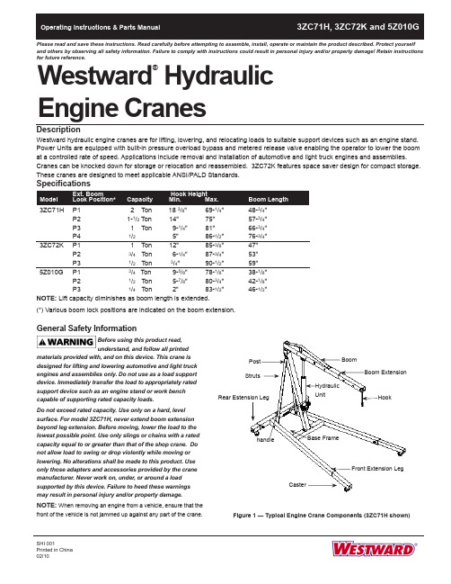
Westward HydraulicPlease read and save these instructions. Read carefully before attempting to assemble, install, operate or maintain the product described. Protect yourself and others by observing all safety information. Failure to comply with instructions could result in personal injury and/or property damage! Retain instructions for future reference.®General Safety InformationBefore using this product read, understand, and follow all printedmaterials provided with, and on this device. This crane is designed for lifting and lowering automotive and light truck engines and assemblies only. Do not use as a load support device. Immediately transfer the load to appropriately rated support device such as an engine stand or work bench capable of supporting rated capacity loads.Do not exceed rated capacity. Use only on a hard, level surface. For model 3ZC71H, never extend boom extension beyond leg extension. Before moving, lower the load to the lowest possible point. Use only slings or chains with a rated capacity equal to or greater than that of the shop crane. Do not allow load to swing or drop violently while moving or lowering. No alterations shall be made to this product. Use only those adapters and accessories provided by the crane manufacturer. Never work on, under, or around a load supported by this device. Failure to heed these warnings may result in personal injury and/or property damage.NOTE: When removing an engine from a vehicle, ensure that thefront of the vehicle is not jammed up against any part of the crane.SHI 001Printed in China BoomHydraulic UnitStrutsCasterFigure 1 — Typical Engine Crane Components (3ZC71H shown)AssemblyMODEL 3ZC71H (Refer to Figure 2)1. Attach swivel casters (No.12) to front extension legs (No.8) and rear extension legs (No.9) with washers and bolts (No.13).NOTE: Do not tighten any bolts unless told to do so.2. Place rear extension leg & frontextension legs inside base frame (No.1) with caster facing down and secure with bolt in frame, tighten bolts.3. Place post (No.4) on the base frame and secure with bolts (No.18).4. Put struts (No.10) on each side of post at top and secure with bolt and nut (No.14). Do not tighten. Place bottom of support on inside of base frame and secure with bolt and nut. (No.14).5. Attach base bracket (No. 20) to hydraulic unit (No.7) with bolts and nuts.6. Attach hydraulic unit assembly on post using bolt and nut (No.17).7. Place boom (No.5) on top of post and secure with bolt and nut (No.16). Pump ram using handle (No.19) until ram is approximately 2” above top. Place front mounting bracket on boom, on top of ram and secure with bolt and nut(No.15). Tighten all bolts in step 8 and step 9.8. Slide boom extension (No.6) inside of boom, making sure slot for chain & hook assembly (No.11) faces down and secure with bolt and nut (No.17) incorrect hole on boom for your particular job.9. Slide chain and hook through slot in lower front of boom extension and secure with bolt and nut (No.11).NOTE: Check all bolts and nuts fortightness, including those pre-assembled at the factory. Tighten where required.Westward Operating Instructions and Parts ManualWestward Hydraulic Engine Cranes®3ZC71H, 3ZC72K and 5Z010GFigure 2 — Assembly Parts Illustration for Models 3ZC71HIMPORTANT: Reference numbers are for assembly purposes only. See appropriate replacement partsillustration of your model for partsordering.141120171818Size of Hardware Kits11*- bolt & nut - M12X75 & M1213 - bolt & washer - M8X1614 - bolt & nut - M12X90 & M1215 - bolt & nut - M16X90 & M1616 - bolt & nut - M20X120 & M2017 - bolt & nut - M16X90 & M1618 - bolt - M12X2520*- bolt, washer & nut - M10X30 & M10* part of assemblyWestward Operating Instructions and Parts ManualModels 3ZC71H, 3ZC72K and 5Z010GMODEL 5Z010G (Refer to Figure 4)1. Attach swivel casters (No.13) to rear support (No.1) with bolts, nuts and washers (No.15).2. Attach wheel (No.17) to front legs (No.2 & 3) with bolts and nuts.NOTE: Do not tighten any bolts unless told to do so.3. Attach front legs (No.2 & 3) to rear support (No.1) with bolts and nuts (No.25).4. Place post support (No.26) on front legs and secure with bolts and washers (No.27).5. Place post (No.4) on post support(No.26) and secure with bolts and nuts (No.23).6. Put strut (No.7) on each side of post, secure the top with bolts and nuts(No.21), place angled portion of support on inside of each front leg and secure with bolt and nut (No.24).7. Attach boom (No.5) on post with bolt and nut (No.20).8. Attach base bracket (No.29) to hydraulic unit (No.9) with bolts andnuts. Place the hydraulic unit with base bracket to post, secure with bolt and nut (No.22) then pump the unit up until it reaches the boom and attach the upper part of unit to boom with bolt and nut (No.19).9. Slide boom extension (No.6) inside of boom (No.5), secure square washer (No.10) and bolt and lock washer(No.10), and secure the boomextension to boom in correct hole for particular job with lock pin and “R” pin (No.12).10. Attach hook (No.8) to boom extension(No.6) with bolt and nut.11. Tighten all bolts and nuts, the enginecrane is ready for use.IMPORTANT : Use boom in its retracted position whenever possible. Extend boom only when necessary to reach load. Be sure load is within capacity limit for boom position selected. If load is to be moved to another location, raise only high enough to clear floor, move crane slowly and avoid sudden stop that could cause load to swing (all models) violently.Westward Operating Instructions and Parts ManualWestward Hydraulic Engine Cranes®3ZC71H, 3ZC72K, and 5Z010GFigure 4 — Assembly Parts Illustration for Model 5Z010GIMPORTANT: Reference numbers are for assembly purposes only. See appropriate replacement parts illustration of your model for parts ordering.1234562189101212131517192020217222223242526272325299Size of Hardware Kits8* - bolt, washer & nut - M12X70 & M1210*- bolt - M8 X 1615 - bolt, washer & nut - M8X16 & M817*- bolt, washer & nut - M12X70 & M1219 - bolt, washer & nut - M12X85 & M1220 - bolt, washer & nut - M16X90 & M1621 - bolt, washer & nut - M12X70 & M1222 - bolt, washer & nut - M14X65 & M1423 - bolt, washer & nut - M10X60 & M1024 - bolt, washer & nut - M12X30 & M1225 - bolt, washer & nut - M12X70 & M1227 - bolt & washer - M12X2029* - bolt, washer & nut - M8X30 & M8* part of assemblyWestward Operating Instructions and Parts Manual OperationPuRGE AIR PRIOR TO OPERATION Sometimes during shipment and/or handling, air gets into hydraulic system causing poor lifting performance. T o correct this:1. Open release valve by turning it counterclockwise two full turns.2. Pump hydraulic unit about 6 full strokes.3. Close release valve and continue pumping until boom has raised several feet.4. Open release valve and slowly lower boom.NOTE: Avoid overtightening release valve - the tighter it is closed the harder it is to crack open for very slow lowering. OPERATING THE CRANENOTE: Capacity of crane varies with boom position. (See boom or Specifications chart.)1. Use boom in its retracted position, whenever possible.2. Extend boom only when necessary to reach load.3. Be sure load is within capacity limit for boom position selected.4. Close release valve (do not overtighten) and pump to raise load to desired height.IMPORTANT: If load is to be moved to another location, raise only high enough to clear floor. Move crane slowly and avoid sudden stops that could cause load to swing violently.CHANGING BOOM ExTENSIONDo not try to change boom position whileunder load. Do not exceed load capacity.NOTE: Check load rating located onboom or on Specifications chart.1. Place boom in horizontal position.2. Move boom and secure with pin and “R”clip.MaintenanceGENERAL1. Avoid overloads.2. Keep hook clean and inspectoccasionally for damage.3. Oil all moving joints periodically (at leastevery 30 days) with a medium weightmachine oil or motor oil.4. Keep sufficient hydraulic jack oil inreservoir.Do not use brake orshock absorberfluids. They have ingredients harmful to thejack’s oil seals.ADDING OIL1. Make sure boom is in lowered position.2. Remove oil fill plug from hydraulic unit.3. Squirt clean hydraulic jack oil into hole.NOTE: In most cases, the addition of afew ounces of oil is sufficient.4. Fill to level of filler hole. Do NotOverfill.RuST PREvENTION1. Check ram and plunger every 3 monthsfor rust or corrosion.2. Clean as needed and wipe with an oilycloth.NOTE: When not in use always positionboom and pump plunger all the way down.STORAGEWhen not in use, store the crane with thelegs folded and secured with the bolt pinsand “R” lock pins (Model 3ZC72K only).NOTE:If necessary to move the cranewith legs in the storage position, do sowith care and only across a smooth,level, seamless surface.See illustration below for details ofsecuring legs for storage.Models 3ZC71H, 3ZC72K and 5Z010G3ZC71H, 3ZC72K, and 5Z010G Westward Operating Instructions and Parts ManualWestward Hydraulic Engine CranesTroubleshooting ChartCrane will not lift load 1. Release valve not tightly closed 1. Ensure release valve tightly closed2. Overload condition 2. Remedy overload conditionCrane will lift, but not maintaining 1. Release valve not tightly closed 1. Ensure release valve tightly closed pressure 2. Overload condition 2. Remedy overload condition3. Hydraulic unit malfunctioning 3. ReplaceCrane will not lower after unloading 1. Reservoir overfilled 1. Drain fluid to proper level2. Linkages binding 2. Clean and lubricate moving parts Poor lift performance 1. Fluid level low 1. Ensure proper fluid level2. Air trapped in system 2. With ram fully retracted, remove oilfiller plug to let pressurized airescape, reinstall oil filler plugWill not lift to full height 1. Fluid level low 1. Ensure proper fluid level1 Hydraulic Unit BL80-60000-000 12 Oil Filler Plug 5905-00100-200 13 Pump Handle BL80-20000-000 14 Hydraulic Unit Bracket T473-00005-000 15 Boom Extension T473-00006-000 16 Braces T473-00001-000 27 Rear Leg Extension T473-40000-100 28 Frong Leg Extension T473-50000-100 29 Caster, 3-1/2" T473-04000-000 410 Hook Assembly T473-05000-000 1• Hardware Kit T473-06000-000 1 ** Seal Kit, Hydraulic Unit BL800S-034 1Please provide following information:-Model number-Serial number (if any)-Part descriptions and number as shown in parts list Address parts correspondence to:Grainger Parts P .O. Box 30741657 Shermer RoadNorthbrook, IL 60065-3074 U.S.A.1Hydraulic Unit BL80-50000-000 1 2Oil Filler Plug 5905-00100-100 1 3 Pump HandleBL80-20000-000 1 4 Hydraulic Unit Bracket T473-00005-000 1 5 Boom Extension T474-08000-000 1 6 BracesT474-00001-000 1 7 Front Wheel, 3-1/2" T474-00002-000 2 8 Middle Wheel. 3-1/2" T474-00002-000 2 9 Caster, 3-1/2" T474-04000-000 210 Hook Assembly T474-07000-000 1 11 Lock Pin T474-03000-000 2 • Hardware KitT474-50000-000 1**Seal Kit, Hydraulic Unit BL800S-034 1ReferencePart Number For Model: NumberDescription3ZC72K (1 Ton)Quantity.Repair Parts ListWestward Operating Instructions and Parts Manual3ZC71H, 3ZC72K and 5Z010G For Repair Parts, call 1-800-323-06201 Hydraulic Unit BL40-40000-000 12 Pump Handle BL80-20000-000 13 Hydraulic Unit Bracket T010-00005-000 14 Boom Extension T077-10000-000 15 Braces T077-00001-000 16 Front Wheel, 3-1/2" T474-90004-K18 27 Caster, T474-04000-000 28 Hook Assembly, Chain and Hook T375-50000-000 13ZC71H, 3ZC72K and 5Z010GWestward Operating Instructions and Parts ManualWestward Hydraulic Engine Cranes®11。
2004年重量级移动地板吊车说明书
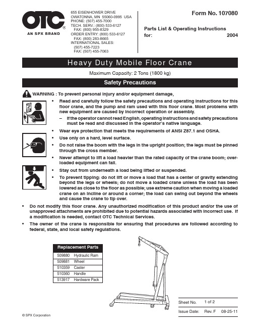
Sheet No.Issue Date:Rev. F08-25-11Parts List & Operating Instructionsfor: 2004Form No. 107080Maximum Capacity: 2 T ons (1800 kg)Read and carefully follow the safety precautions and operating instructions for this •floor crane, and the pump and ram used with this floor crane. Most problems with new equipment are caused by incorrect operation or assembly.If the operator cannot read English, operating instructions and safety precautions–must be read and discussed in the operator’s native language.W ear eye protection that meets the requirements of ANSI Z87.1 and OSHA. • Use only on a hard, level surface.• Do not raise the boom with the legs in the upright position; the legs must be pinned • through the cross member.Never attempt to lift a load heavier than the rated capacity of the crane boom; over-• loaded equipment can fail.S tay out from underneath a load being lifted or suspended.• To prevent tipping: do not lift or move a load that has a center of gravity extending •beyond the legs or wheels; do not move a loaded crane unless the load has been lowered as close to the floor as possible; use extreme caution when moving a loaded crane on an incline or around a corner; the load can swing out beyond the wheels and cause the crane to tip over.D o not modify this floor crane. Any unauthorized modification of this product and/or the use of• unapproved attachments are prohibited due to potential hazards associated with incorrect use. If a modification is needed, contact OTC Technical Services. T he owner of the crane is responsible for ensuring that procedures are followed according to• federal, state, and local safety regulations.655 EISENHOWER DRIVEOWATONNA, MN 55060-0995 USA PHONE: (507) 455-7000TECH. SERV.: (800) 533-6127 FAX: (800) 955-8329ORDER ENTRY: (800) 533-6127 FAX: (800) 283-8665INTERNATIONAL SALES: (507) 455-7223FAX: (507) 455-7063© SPX Corporation1 of 2Parts List & Operating InstructionsForm No. 107080, Sheet 1 of 2, Back1. Align holes on rear caster wheels (Item No. 13) with match-ing holes on base (1), and attach with bolts (24), washers (31), and nuts (30). Align holes on front caster wheels (Item No. 14) with matching holes on base (1), and attach with bolts (25), washers (31), and nuts (30). Slide bushings (35) through wheels (33), and install wheels into welded forks in front of each leg extension (5, 6) with bolts (34), washers (36), and nuts (37).2. Slide leg extensions into open ends of base. Install bolts (23), nuts (29), lock pins (12), and cotter pins (32) to se-curely hold leg extensions to base.3. Install upright mast (2) onto base using bolts (19) and nuts (27). Install mast braces (7) onto base using bolts (19) and nuts (27). Align holes at upper end of mast braces with second hole from the top in upright mast using bolt (19) and nut (27). Once aligned, securely tighten bolts.Item No. DescriptionQty.1 Base 12 Upright Mast 13 Boom 14 Boom Extension 15 Leg Extension (left) 16 Leg Extension (right) 17 Mast Braces 2 2 Lock Pin2 13 Swivel Caster (3.5") 2 14 Swivel Caster (2.5") 2 15 Hook & Chain 16 Hydraulic Ram7 Handle18 Bolt (M20 × 120) 1 19 Bolt (M14 × 100) 5 20 Bolt (M14 × 80) 1 21 Bolt (M16 × 90) 2 22 Bolt (M16 × 70) 1 23 Bolt (M18 ×110) 2 24 Bolt (M8 × 25) 8 25 Bolt (M8 × 20) 8 26 Nut (M20) 27 Nut (M14) 5 28 Nut (M16) 3 29 Nut (M18) 2 30 Nut (M8)6 31 Spring Washer 8 16 32 Cotter Pin (2.5") 2 33 Wheel2 34 Bolt (M10 × 80) 2 35 Bushing 2 36 Washer 0 4 37 Nut (M10) 2 38 Nut (M14) 39Washer 204. Install hydraulic ram (16) to support bracket on upright mast using bolt (21) and nut (28). Once secure, tem-porarily rest the ram against the upright mast.5. Install boom (3) on top of upright mast, and secure with bolt (18), washer (39), and nut (26).6. Align and install top of hydraulic ram into welded fork on boom, and secure with bolt (22) and nut (28).7. Slide boom extension (4) into boom, and secure with bolt (21) and nut (28).8. Install hook and chain (15) at end of boom extension using bolt (20) and nut (38). Slide handle (17) on socket on hydraulic ram.39243113181622332038326231721282302727197719619192719145271321273028143237121225313523132293629343633415Sheet No. Issue Date:Rev. F08-25-111. Lock the boom in place for the correct weight marking BEFORE APPL YING THE LOAD TO THE LIFT. Do NOT exceed the rated capacity and travel limits of the equipment.2. Use correct levellers, slings, or chains (capable of sustaining the load) around the load before using the hook to lift it. Verify the latching mechanism is working correctly before lifting or moving the load.3. Once the load is securely hooked in place, lift by turning the release valve on the hydraulic jack clockwise until closed and pumping the jack until the load is clear of any obstruction. Move very carefully, avoiding slopes, in direction of travel. Avoid sudden or swinging movements of the load. T o lower the load, SLOWL Y turn release valve counterclockwise.Storage1. Lower the boom to its lowest position.2. Remove bolts, nuts, and lock pins holding leg extensions to base. Remove leg extensions from base, and position them vertically in storage pockets located slightly behind the front caster wheels.3. Reinstall bolts, nuts, and lock pins removed in Step 2 to secure leg extensions in vertical position.Troubleshooting GuideRepair procedures must be performed in a dirt-free environment by qualified personnel who are familiar with this equip-ment. CAUTION: All inspection, maintenance, and repair procedures must be performed when the floor crane is free of load (not in use).Trouble CauseSolutionFailure to lift a loadFailure to hold a loadLift arm will not lower Jack feels spongy when lifting1. Low oil level.2. Release valve open.1. Release valve open.2. Jack is air locked.3. Dirt in oil.4. Release valve not sealing.1. Ram is binding.1. Jack is air locked.1. Turn release valve counterclockwise to allow ram to fully retract. Remove fi ll plug. With jack in vertical position, oil level should be even with bottom of hole. If not, fi ll with NEW, clean, hydraulic jack oil. Recheck oil level. Do NOT overfi ll. Replace fi ller plug.2. Close release valve.1. Close release valve (turn clockwise - CW).2. Turn release valve counterclockwise (CCW) to open. Pump handle 8 strokes. Close release valve (CW). Pump handle until lift arm reaches maximum height; continue to pump several times to remove trapped air in ram. Open release valve; allow lift arm to retract. Close release valve; check pump action. Repeat procedure if necessary.3. Replace existing oil with NEW, clean, hydraulic jack oil.4. Clean release valve.1. Replace hydraulic ram.1. Turn release valve counterclockwise (CCW) to open. Pump handle 8 strokes. Close release valve (CW). Pump handle until lift arm reaches maximum height; continue to pump several times to remove trapped air in ram. Open release valve; allow lift arm to retract. Close release valve; check pump action. Repeat procedure if necessary.MaintenanceInspect the floor crane before each use. Look at the jack support, boom, or boom extension for cracked welds, bent, loose, or •missing parts, or hydraulic oil leaks. If the crane is damaged in any way, worn, or operating abnormally, IT MUST BE REMOVED FROM SERVICE UNTIL REPAIRED.Ahydraulic jack found to be damaged in any way, worn, or operating abnormally MUST BE REMOVED FROM SERVICE UNTIL •REPAIRED. If the jack is subjected to abnormal load or shock, remove it from service and have it examined by an authorized repair service. Only factory-authorized parts, labels, and decals shall be used on this equipment.Look for unauthorized modification of this product. Modifications to this product and/or the use of unapproved attachments are • prohibited due to potential hazards associated with incorrect use.C lean all surfaces and maintain all labels and warnings.•G rease pivot points: boom to upright mast; ram mount to boom.•Parts List & Operating InstructionsForm No. 1070802 of 2。
CD225 吊车式吊车辆数据手册-英制说明书

CD225CAB DOWN CRANECD225DATASHEET -IMPERIALFeatures:Rated capacity:25 ton @10 ft working radius Maximum boom length: 72 ftMaximum tip height:121 ftCONTENTSCD225Page: Key. . . . . . . . . . . . . . . . . . . . . . . . . . . . . . . . . . . . . . . . . . . . . . . . . . . . . . . . . . . . . . . . . . . . . . . . . . . . . . . . . . . . . . . . . . . .3DimensionsCrane dimensions . . . . . . . . . . . . . . . . . . . . . . . . . . . . . . . . . . . . . . . . . . . . . . . . . . . . . . . . . . . . . . . . . . . . . . . . . .4 Crane weights . . . . . . . . . . . . . . . . . . . . . . . . . . . . . . . . . . . . . . . . . . . . . . . . . . . . . . . . . . . . . . . . . . . . . . . . . . . . . .5Load ChartsRange Diagram – Main Boom – Outriggers fully extended (100%) . . . . . . . . . . . . . . . . . . . . . . . . . . . . . .6 Load Chart – Main Boom – Outriggers fully extended (100%) . . . . . . . . . . . . . . . . . . . . . . . . . . . . . . . . . .7 Range Diagram – Main Boom – 26 ft offsettable jib . . . . . . . . . . . . . . . . . . . . . . . . . . . . . . . . . . . . . . . . . . .8 Load Chart – Main Boom – 26 ft offsettable jib . . . . . . . . . . . . . . . . . . . . . . . . . . . . . . . . . . . . . . . . . . . . . . .9 Range Diagram – Main Boom – 43 ft offsettable jib . . . . . . . . . . . . . . . . . . . . . . . . . . . . . . . . . . . . . . . . . . .10 Load Chart – Main Boom – 43 ft offsettable jib . . . . . . . . . . . . . . . . . . . . . . . . . . . . . . . . . . . . . . . . . . . . . . .11 Range Diagram – Main Boom – On tires . . . . . . . . . . . . . . . . . . . . . . . . . . . . . . . . . . . . . . . . . . . . . . . . . . . . . .12 Load Chart – Main Boom – On tires . . . . . . . . . . . . . . . . . . . . . . . . . . . . . . . . . . . . . . . . . . . . . . . . . . . . . . . . . .13Technical DescriptionBoom . . . . . . . . . . . . . . . . . . . . . . . . . . . . . . . . . . . . . . . . . . . . . . . . . . . . . . . . . . . . . . . . . . . . . . . . . . . . . . . . . . . . . .14 Hoist, rope and hook . . . . . . . . . . . . . . . . . . . . . . . . . . . . . . . . . . . . . . . . . . . . . . . . . . . . . . . . . . . . . . . . . . . . . . .14,15 Superstructure . . . . . . . . . . . . . . . . . . . . . . . . . . . . . . . . . . . . . . . . . . . . . . . . . . . . . . . . . . . . . . . . . . . . . . . . . . . . .15 Cab, controls, operator aids and load limiter/load indicator . . . . . . . . . . . . . . . . . . . . . . . . . . . . . . . . . .15,16 Carrier, engine, drive-line and hydraulic system . . . . . . . . . . . . . . . . . . . . . . . . . . . . . . . . . . . . . . . . . . . . . . .16 Vehicle performance . . . . . . . . . . . . . . . . . . . . . . . . . . . . . . . . . . . . . . . . . . . . . . . . . . . . . . . . . . . . . . . . . . . . . . . .17 Tires . . . . . . . . . . . . . . . . . . . . . . . . . . . . . . . . . . . . . . . . . . . . . . . . . . . . . . . . . . . . . . . . . . . . . . . . . . . . . . . . . . . . . . .172CD225 KEYCounterweightMain boomBoom lengthTip heightBoom with extensionMain boom with aux headSlewing / Allowable slewing range Slewing brakeOutriggers / Lifting on outriggers(100/50/0% extended)Main hoistHoist speedRope –Standard / OptionalRope diameterHook blockCabOperator aids / Load limiter / Load indicator Mechanical transmissionHydraulicsWorking temperatureLightsCrane / Crane in standard configuration Crane without counterweight General performanceTelescoping modeBoom luffing angleWorking radiusMax. boom length with extensionDistance from the hook to the head sheave pin Slewing locked / Slewing locked at specified position Slewing gearsLifting on wheels / Pick & CarryAuxiliary hoistRope lengthMax. line pullTireControlsEngineSteeringSpeedHeating / Air conditioningGradeabilityGross vehicle weightWeight on front axleWeight on rear axle3CRANE DIMENSIONSCD2254Note:14.00 x 2420.5 x 25Track width 6’.9.9’’6’-10.5’’Overall width8’-0’’8’-8’’Note:All heights are based on 20.5 x 25 tires. Use of 14.00 x 24 tires will reduce height by 2.5’’.CRANE WEIGHTSApproximate WeightsCD2255STD (without hoo block and auxiliary hoist)42,534 lb20,480 lb22,054 lb Add / Subtract for main optional equipment26 ft to 43 ft swing on jib stowed61 ft boom+1490 lb+ 1944 lb–454 lb72 ft boom+1490 lb+ 2489 lb–999 lbAuxiliary boom head61 ft boom+ 100 lb+ 257 lb–158 lb72 ft boom+ 100 lb+ 290 lb+ 191 lbAuxiliary hoist*+ 115 lb–25 lb+ 140 lb 25T, 2 sheave hook block+ 682 lb+ 1155 lb–473 lb 7T, hook and ball (in tool box)+ 240 lb+ 81 lb+ 159 lbNOTE: Values are subject to 2% variation * Weight includes ropeCD225with hook block:4 ft5 inRANGE DIAGRAM –MAIN BOOMOutriggers Fully Extended (100%)6CD225 LOAD CHART –MAIN BOOMOutriggers Fully Extended (100%)Standard ASMEB30.57CD225with hook block:4 ft5 inRANGE DIAGRAM –MAIN BOOMWith Jib, 26 ft offset89CD225LOAD CHART –MAIN BOOMWith Jib, 26 ft offset7,200 lbs14 ft 6 in(100%)360°Standard ASMEB30.5CD225with hook block:4 ft5 inRANGE DIAGRAM –MAIN BOOMWith Jib, 43 ft offset10CD225 LOAD CHART –MAIN BOOMWith Jib, 43 ft offset7,200 lbs14 ft 6 in (100%)360°Standard ASMEB30.511CD225with hook block:4 ft5 inRANGE DIAGRAM –MAIN BOOMOn Tires1213CD225Notes to lifting capacityLifting capacities do not exceed 85% of tipping load. Weight of hook blocks and slings is part of the load, and is to be deducted from the capacity ratings. Consult operation manual for further details.Note: Data published herein is intended as a guide only and shall not be construed to warrant applicability for lifting purposes.Crane operation is subject to the computer charts and operation manual both supplied with the crane.360°BoomStandard configuration:3 sections hydraulic actuated boomFull power mechanically synchronizedMin. / Max.30 ft / 72 ftBoom elevation angle range (min. / max.)-4° / 76°Optional configuration:One section jib26 ftOffset0, 15 and 30 degreesMaximum tip height103 ftTwo section jib26 ft to 43 ftOffset0, 15 and 30 degreesMaximum tip height121 ft Hoist, Rope and HookStandard configuration:Grooved drumStorage capacity570 ftTwo speed ratiosWithout load in 5th layer (low range / high range)227 ft/min / 364 ft/minWithout load in 1st layer (low range / high range)157 ft/min / 252 ft/min6 x 19 IWRC XIPS, right regular lay, preformed5/8 in455 ftMax. line pull; 1st layer low-range12,510 lbsMax. line pull permissible9,000 lbs14Optional configuration:Hook and ball239 lbs2 sheaves680 lbs3 sheaves660 lbs4 sheaves660 lbsGrooved drumStorage capacity570 ftWithout load in 5th layer (low range / high range)227 ft/min / 364 ft/minWithout load in 1st layer (low range / high range)157 ft/min / 252 ft/minRotation resistant compacted strand 18 x 19 or 19 x 195/8 in455 ftMinimum breaking strength 35,800 lbsMax. line pull permissible9,000 lbs SuperstructureStandard configuration:Non stop360ºMaximum rotation speed without load 3 rpmHydraulic motorPlanetary reducer360ºhouse lockManually actuated by foot pedalCab, Controls, Operator aids and Load limiter / Load indicatorStandard configuration:Rubber floor matTinted safety glassSix way adjustable seatArmrest mounted dual axis electro-proportional joysticksSteering wheel column with gear selector on the left and directional light selector on the rightDashboard mounted switches for outrigger operationGraphic interface for load indicator15Optional configuration:Hydraulic powered air conditionerHydraulic powered heaterWork lightsRotating beaconCarrier, Engine, Drive-line and Hydraulic systemStandard configuration:Hydraulic, independent extension:Diameter of outrigger pads24 inArea of outrigger pads452 in2Cummins QSB4.54 cylindersRated power130 hp @ 2,300 rpmMaximum gross torque459 ft·lb @ 1,500 rpmIntake: turbocharger with intercoolerFuel type DieselFuel tank capacity50 gallons6 x 6 powershift transmission with integral torque converterFull time 4WD (Four-Wheel Drive)Rigid mounted front axleOscillating rear axleDifferential lock on front axle and rear axleRear axle oscillation lock – manual or automatic actuationAir-over-hydraulic disc brakesParking brake on front axleHydraulic oil cooler on carrierHydraulic power steeringFront wheel steeringFour wheel steering concentricFour wheel steering crabOptional rear wheel steering packageHydraulic Pumps:Tandem pumps:Boom lift / T elescope30 gal/min @ 3,500 psiPower steering / Outriggers and Swing21 gal/min @ 2,500 psiSingle pump:Main and auxiliary hoist pump41 gal/min @ 3,500 psiHydraulic oil reservoir capacity94 gallonsHydraulic oil suction filter250 micronsHydraulic oil return filter 5 microns16Vehicle performanceStandard configuration:Max. in 1st gear (low range)112 %Max. in 3rd gear (high range) 3.8 %Max. (6th gear)24.5 mph TiresStandard configuration:Wide tread earth mover pattern (E3)20.5 x 25-20 PROptional configuration:Industrial pattern14.00 x 24-20 PR 17CD225Effective Date: October 2010.Product specifications and prices are subject to change without notice or obligation. The photographs and/or drawings in this document are for illustrativep urposes only. Refer to the appropriate Operator’s Manual for i nstructions on the p roper use of this equipment. F ailure to follow the a ppropriate Operator’sM anual when using our equipment or to otherwise act i rresponsibly may result in s erious injury or death. The only w arranty applicable to our equipment isthe standard written warranty a pplicable to the particular product and sale and T erex makes no other warranty, e xpress or i mplied. P roducts and services listed may be trademarks, service marks or trade-names of T erex C orporation and/or its s ubsidiaries in the USA and other countries. All rights are reserved.T erex®is a r egistered trademark of T erex Corporation in the USA and many other c ountries.Copyright 2010 T erex CorporationT erex Cranes, Global Marketing, Dinglerstraße 24, 66482 Zweibrücken, GermanyT el.+49(0)6332830,Email:*********************,Brochure Reference: TC-DS-I-E-CD225-10/10。
2000T港口门吊电气设计之二
2000港口门吊电气部分设计之二中铁工程机械研究设计院容毅㈣方案介绍及关键技术4.1概述电气控制系统采用工控机、PLC可编程控制器(以下简称PLC)、变频器等先进成熟的技术,组成了LCMS起重机监控和管理系统,并预留了港区远端RCMS和(广域网)远程TCMS (telenet CraneMonitor System)的功能接口。
实现起重机各机构的平稳调速和整机的管理。
整机具备完善的保护和故障自诊断等功能。
具有同货场指挥调度中心联网,实现资源共享的条件。
选用西门子公司SIMATICS7系列PLC可编程控制器、施耐德公司的变频器。
LCMS系统的最上层为单台设备运行管理层。
由触摸屏、工业控制计算机、打印机、组态软件等组成。
通过PROFIBUS总线与PLC间的通讯,获取门吊实时信息,完成门吊运行信息的采集及分析,历史数据、故障提示及分析等功能,对生产过程进行全程跟踪。
中间层为PLC,是系统的实时控制核心。
PLC通过PROFIBUS-DP总线方式经远端PLC 分站与各机构的变频器相连,实现PLC和变频装置之间的通讯,获取变频器的运行与故障信息,完成对各机构的监视和控制。
最下层为主传动层。
起升机构、大车运行机构、小车运行机构和辅助吊机构均采用施耐德ATV 71变频器。
起升机构采用全数字式、矢量控制方式,带速度传感器及PG卡反馈实现闭环控制。
所有变频器挂在PROFIBUS总线网络上,实现PLC的统一控制。
起重机电气设备的选择具有先进性,可靠性。
电气设备的布置充分考虑维修操作安全方便。
所有电气设备元件满足有关规范标准的要求,达到所要求的性能指标,满足机构工作级别和起重机安装地环境条件。
所有电气设备、元件有防尘、耐腐蚀、耐热、去湿措施。
4.1.1动力电缆卷盘本机动力电缆卷筒选用上海振华伟龙公司产品。
大车电缆参数:创世拓10KV 3*35+3*10 ,自重 3.05kg/m ,最大直径:φ44.7mm,许用拉力(静态/动态):3000N。
汽车起重机液压系统中英文对照外文翻译文献

汽车起重机液压系统中英文对照外文翻译文献(文档含英文原文和中文翻译)翻译:汽车式起重机液压系统—技术现状与发展趋势一、行业背景(一)国外工程汽车起重机的发展趋势近20年世界工程起重机行业发生了很大变化。
RT(越野轮胎起重机)和AT(全地面起重机)产品的迅速发展,打破了原有产品与市场格局,在经济发展及市场激烈竞争冲击下,导致世界市场进一步趋向一体化。
为与RT和AT产品抗衡,汽车起重机新技术、新产品也在不断发展。
近年来汽车起重机在英、美等国市场的复兴,使人们对汽车起重机产生新的认识。
几年前某些工业界人士曾预测,RT 和AT产品的兴起将导致汽车起重机的衰退。
日本汽车起重机在世界各地日益流行,以及最近格鲁夫、特雷克斯、林克.贝尔特、德马泰克等公司汽车起重机的产品进展,已向上述观念提出挑战。
随着工程起重机各机种间技术的相互渗透与竞争,汽车起重机会在世界市场中继续占有一席之地。
国外工程起重机从整体情况分析,领先国内10~20年(不同类型产品有所不同)。
随着国外经济发展速度趋于平稳,工程起重机向智能、高性能、灵活、适应性强、多功能方向发展。
25t以下基本上不生产,产品向高附加值、大吨位发展,住友建机、多田野和加藤公司曾于1989年相继推出360t汽车起重机。
住友建机在90年代开发出80t~250t共4种AT产品。
多田野也在90年代相继推出100t~550t共6种特大型AT产品。
加藤公司则研制成NK5000型500t汽车起重机。
行业配套也与国内有所不同:1、下车主要是300kW以上柴油大功率发动机,与之配套的液力变矩器和自动换档变速箱、12吨级驱动转向桥及越野轮胎。
2、上车:高强度材料、大扭矩的起升机构、回转机构、回转支承。
3、液压系统:变量泵、变量马达、电磁换向先导阀及主阀、平衡阀、悬挂系统阀、液压锁、液压缸及管路标准配套件。
4、智能控制系统:力限器显示控制、记忆通讯及单缸顺序伸缩自动控制。
(二)国内工程汽车起重机的发展趋势国内工程机械产品近十年来随着技术的引进、消化、吸收,有了长足的进步,产品性能、可靠性、外观都有较大幅度的提高,但同国外工程机械比较来看,还存在较大差距。
桥式(门式 )起重机档案资料及管理要求(公路工程)

桥式(门式)起重机档案资料及管理要求(公路工程)一、出租单位、使用单位对于以下几种类型的设备不得出租和使用。
(1)属国家明令淘汰或者禁止使用的。
(2)超过安全技术标准或者制造厂家规定的使用年限的。
(3)经检验达不到安全技术标准规定的。
(4)没有完整安全技术档案的。
(包括:a特种设备的设计文件、产品质量证合格证明、安装及维护保养说明、监督检验证明等相关技术资料和文件;b 特种设备定期检验和定期自行检查记录;c特种设备的日常使用状况记录;d特种设备及其附属仪器仪表的维护保养记录;e特种设备的运行故障和事故记录。
)(5)没有齐全有效的安全保护装置的。
出租单位应提供建筑起重机械特种设备制造许可证、产品合格证、备案证明和自检合格证明,提交安装使用说明书,并应当应在签订的建筑起重机械租赁合同中,明确租赁双方的安全责任。
二、出租单位资料及管理要求。
(1)购销合同、制造许可证、产品合格证、型式检验报告、质量证明书、附属设施(安全装置、材料)合格证、安装使用说明书、备案证明等原始资料。
(2)定期检验报告、定期自行检查记录、定期维护保养记录、维修和技术改造记录、运行故障和生产安全事故旧录、累计运转记录等运行资料。
(3)历次安装验收资料。
三、安装单位资料及管理要求。
(1)安装单位资质证书、安全生产许可证、安装人员资格证书(Q1、Q2)及名单、现场管理人员及安全管理人员任命书。
(2)安装、拆卸合同。
与使用单位签订。
(3)安全协议书。
与使用单位签订。
(4)安装、拆卸工程专项施工方案。
安装单位按照安全技术标准及建筑起重机械性能要求,编制建筑起重机械安装、拆卸工程专项施工方案,由安装单位技术负责人签字后,报上报总包单位、监理单位审批。
(5)安全施工技术交底的有关资料。
由安装单位现场负责人组织实施,并进行签字按手印确认。
(6)安装、拆卸工程生产安全事故应急救援预案。
由安装单位编、审、批后,报总包单位、监理单位审核。
(7)专项方案(安装、拆除)实施前将安装拆卸单位资质、专项施工方案、安装拆卸人员名单及资格、安装拆卸时间、安装拆卸生产事故应急救援预案、安全技术交底资料、安全管理协议、安装拆卸合同等资料报总包单位、监理单位审核合格后,告知属地市场监督管理局办理安装(维修)告知单后,组织进行安装、拆卸工作。
- 1、下载文档前请自行甄别文档内容的完整性,平台不提供额外的编辑、内容补充、找答案等附加服务。
- 2、"仅部分预览"的文档,不可在线预览部分如存在完整性等问题,可反馈申请退款(可完整预览的文档不适用该条件!)。
- 3、如文档侵犯您的权益,请联系客服反馈,我们会尽快为您处理(人工客服工作时间:9:00-18:30)。
RESET OF THE MIPEG SYSTEM
Note: All calibration data and settings will be lost.
Make sure to write down all calibration data and settings before doing the reset, so the data can be re-entered to the system after completion of this procedure.
Click connect
Enter code for level 4
Click System Page
Click Set Cr.Id.Eeprom
Wait until Ok! is displayed on the Status line
Verify that Crane Ident. No: is identical to Crane Id.No.Eepr: (324 both)
Click Reset Prom Param.
Click OK to reset system
Wait until Ok! is displayed on the Status line Click Set RTC
Wait until Ok! is displayed
Verify that the Real Time Clocks (Date Year and Time) for Mipeg clock and PTU clock are near equal (+/- some seconds)
Click System Page again
Click Reset All
Enter Usage Hours: (Number found in the header of the latest downloaded COR data) Click OK
Enter Number of lifts: (Number found in the header of the latest downloaded COR data) Click OK
Enter Number of Over lifts: (Number found in the header of the latest downloaded COR data)
Click OK
Enter Number of Moment Peaks: (Number found in the header of the latest downloaded COR data)
Click OK
Wait until Ok! is displayed on the Status line.
Click Disconnect.
When system comes up in online mode verify that no error messages are displayed on the Mipeg 2000 Display.
The Reset of the system should now be completed.。
