TB353-U使用手册
柔性检查作用域套件-USB 产品说明书
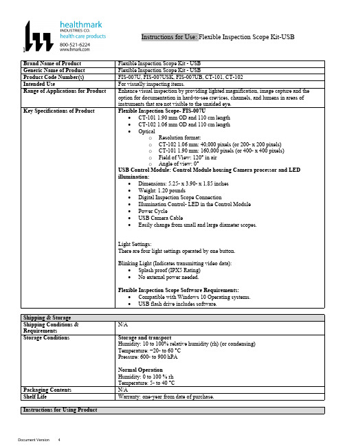
lInstructions for Use: Flexible Inspection Scope Kit-USB Brand Name of ProductFlexible Inspection Scope Kit - USB Generic Name of ProductFlexible Inspection Scope Kit - USB Product Code Number(s)FIS-007U, FIS-007USK, FIS-007UB, CT-101, CT-102Intended UseFor visually inspecting items.Range of Applications for ProductEnhance visual inspection by providing lighted magnification, image capture and the option for documentation in hard-to-see crevices, channels, and lumens in areas of instruments that are not visible to the unaided eye.Key Specifications of Product Flexible Inspection Scope- FIS-007U∙CT-101 1.90 mm OD and 110 cm length∙CT-102 1.06 mm OD and 110 cm length∙Opticalo Resolution format:o CT-102 1.06 mm: 40,000 pixels (or 200- x 200 pixels)o CT-101 1.90 mm: 160,000 pixels (or 400- x 400 pixels)o Field of View: 120° in airo Angle of view: 0°USB Control Module: Control Module housing Camera processor and LEDillumination:∙Dimensions: 5.25- x 3.90- x 1.85 inches∙Weight: 1.20 pounds ∙Digital Inspection Scope Connection∙Illumination Control- LED in the Control Module∙Power Cycle∙USB Camera Cable∙Easily change from small and large diameter scopes.Light Settings:There are four light settings operated by one button.Blinking Light (Indicates transmitting video data):∙Splash proof (IPX5 Rating)∙No external power needed.Flexible Inspection Scope Software Requirements:∙Compatible with Windows 10 Operating systems.∙USB flash drive includes software.Unpacking Flexible Inspection Scope:Carefully inspect for shipping damage. If there is any damage contact the shipping carrier and Heatlhmarkcustomer service 800-521-6224 immediately.USB Control Module: (Fig. 1).1.Digital Inspection Scope Connection 2.Illumination Control 3.Power Cycle B (Type C) on the right side of the boxFigure 1Flexible Inspection Scope™: (Fig. 2).∙CT-101 1.90 mm O.D. and 110 cm length ∙CT-102 1.06 mm O.D. and 110 cm lengthLarge1.90 mmSmall 1.06 mmFigure 2Flexible Inspection Scope™ Features3214Light/Illumination Settings: (Fig. 3).∙Five (5) light settingso Light on control indicats setting levelo Fifth setting is OFF∙Press light button to advance to next setting.∙Fifth setting turns the light OFF.Figure 3Power Cycle ButtonPress button to RESET camera (Fig. 4).Figure 41.Flexible Inspection Scope™ Plug (Fig. 5).Contains camera video connection as well as LED Light for illumination.1Figure 52.Flexible Working Length (Fig. 6).The portion of the Flexible Inspection Scope™ that is inserted into an item during visual inspection.The measuring scale markings on the Flexible Working Length are in centimeters (accuracy = ± 0.5 cm)2Figure 63.Distal Camera (Fig. 7).Distal portion of Flexible Inspection Scope™ that contains the camera lens3Figure 7SOFTWARE INSTALLATION:Note: This section is done only once when connecting the scope to the computer for the first time.∙System Requirements: MS Windows 10∙Install the Flexible Inspection Scope™ Software from the USB flash drive on a computer.Note: If you have any IT policies that may block this installation, please contact your IT team to give access to Healthmark scope viewer to install.1. Insert the USB Flash drive into your computer, and double click on the Healthmark Scope Viewer installer package to begin installation.2. The “Welcome to the Healthmark Scope Viewer Setup Wizard” screen pops up. Click on Next.3. Select the first tab Typical or setup type of your choice, click Next.4. Click Install and wait for installation to complete.5. Click Finish.STARTING SOFTWARE & CONNECTING SCOPE TO PC:(Fig 8).1.Open the Windows PC viewer software.2.Connect the Control Module to PC using USB Cable.3.Plug the Flexible Inspection Scope into the Control Module.4.In the viewer software, click Settings and Select USB Video Device, click on the desiredresolution, select the preferred Video Output Format, and then Click OK.5.Press the Power Cycle Button.Figure 86.Now you can start using the scope.Verifing OperationFollowing the steps listed below will ensure the proper use and performance of the Flexible Inspection Scope™. The Flexile Inspection Scope™ can be checked for normal operation by connecting it as described in the Startup section of this IFU.Normal operation includes:∙An image appearing on your computer monitor or HDMI Monitor.∙ A blinking light on Control Module near the Power Cycle button that indicates the image feed is transmitting.∙White light emitting from the distal end of the Digital Inspection Scope.∙An LED light on the control module top panel that indicates the light intensity of the device. Using SoftwareHealthmark Scope Viewer Software (Fig. 9).1.Capture button: Captures a Reference Image and saves it to the Reference Image folder.2.Main Image Window: Displays the image from the camera.3.Reference Image Window: Displays a reference image.4.Clear Button: Removes the image from the Reference image window.5.Open Reference Image button: Allows selection of a reference image from the Reference Imagefolder.6.Settings Button: Click to select the video camera and resolution settings.7.File Location Button: Click to change location where captured images are being saved.8.File Location Window: Shows the file path where captured images are being saved currently.9.Capture Image Button: Captures images and adds them to the File Location selected by the user(as shown in the File Location Window).10.Capture Video button: Click to record video. Click again to stop recording video.11.File Prefix: Type in text that you would like included in the file name of Captured Images.Figure 9Selecting Video Device or CameraFollow the directions below to select the video device or camera used to capture images using the Flexible Inspection Scope™ Viewer Software. (Fig. 10).1.Click Settings button in the lower left of the Scope Viewer software to display a list of videodevices or cameras being detected by your computer2.Select a device for capturing images using the Scope Viewera.The example below shows a webcam and USB Video Device in the Settings box. Select theUSB Video Device for the Flexible Inspection Scope™.b.You can also select your preferred Video Output Format from the dropdown box3.Click OK to view the selected Video Device.231Figure 10Capturing Still PicturesFollow the instructions for capturing still pictures from the Main Image Window.Select the Capture Image button. (Fig. 11).Figure 11Note: When an image is captured, “Image Captured” in red text will flash on the lower portion of the screen and a new file will appear in the Files Location.Capturing Video ImagesFollow the instructions below for capturing video from the Main Image Window.1.Select the Capture Video Button (Fig. 12).Figure 122.When the video is recording “Recording…” in red text will appear toward the bottom of thesoftware window.3.To stop recording, click Stop Capture. (Fig. 13).Figure 13Setting File PrefixFollowing the steps below allows you to create a file prefix that will appear after the underscore of image file names save to the File Location specified by the user.1.Click in the field next to File Prefix.2.Enter the characters that you would like to be included in the file name. (Fig 14).Figure 14Setting Location for Saved FilesFollowing the steps below allows you to set the file location of saved images using the Scope Viewer software.1.Click the File Location button.2.Select the file location you want to save captured images. (Fig 15).Figure 15Displaying Reference ImageThere are two ways to display a still image in the Reference Image Window on the Scope Viewer software.1.To display an image currently being displayed in the Main Image Window, click the Capture button. Note: The images will be saved in a file folder titled Reference Images in the designated File Location that the user specified in the File Location field. (Fig. 16).Figure 162.To display a saved image in the Reference Image Window from your File Location:a.Click the Open Reference Image button (Fig. 16 above).b.Select the file you want to display (Fig. 17 below).c.Click the OK Button, to display the image in the Reference Image Window. (Fig. 17).Figure 17Switching to a Different Flexible Inspection Scope™ on the Control Module:1.Press the Power button on the Control Module once.2.Disconnect the current Flexible Inspection Scope from the Control Module.3.Repeat the steps in the “STARTING SOFTWARE & CONNECTING SCOPE TO PC” procedure.Inserting Scope in ItemFigure 1Rotating Device to Avoid ObstacleFigure 2 Performing InspectionWipe down the Flexible Inspection Scope™ with a compatible wipe. Follow the manufacturer’s (Mfr.’s)Instructions for Use (IFU) for appropriate wipe usage. Click here to see the Chemical Compatibility Chart(PDF) for approved cleaning.The Flexible Inspection Scope™ is made of the same material as other common endoscopes. Any wipe,solution, or low temperature (≤ 60 °C [140 °F]) method intended for the reprocessing of endoscopes is likelycompatible with the Generation II Flexible Inspection Scope™ Catheters if used according to the productlabeling.Solutions Containing (Flexible Inspection Scope Only)Alcohol Ethoxylates Neutral or Near-Neutral pH DetergentsEnzymatic Cleaning Solutions Enzymatic DetergentsSodium Borated, Decahydrate Tetrapotassium PyrophosphateFlexible Inspection Scope™ has a fluid ingress protection rating of IPX7 (Waterproof) and can withstandimmersion in fluid up to one (1)-meter in depth for up to 30 minutes.Control Module USB has a fluid ingress protection rating of IPX5 (Water resistant) and can withstand asustained, low pressure water jet spray for up to three minutes.For Thorough Cleaning: CablesFollow the cleaning agent Mfr.’s IFU.1.Unplug and disconnect all components from the Control box prior to cleaning.2.Do not submerge or soak the cable for disinfection (cable is not waterproof).3.Wipe thoroughly with non-linting wipe moistened with facility approved neutral detergent. Use theappropriate brushes with detergent solution to remove any residues from areas that cannot bereached with the wipes.For Thorough Cleaning: Control Module1.Unplug and disconnect all components from the Control box prior to cleaning.2.Do not submerge or soak the cable for disinfection (Control Box is not waterproof).3.Wipe thoroughly with non-linting wipe moistened with facility approved neutral detergent. Use theappropriate brushes with detergent solution to remove any residues from areas that cannot bereached with the wipes.Note: Do NOT soak. Control Module and cables are not waterproof and should not be immersed.N/ACleaning –AutomatedDisinfection Control Module and CablesThese may be cleaned with alcohol based disinfectant wipes.Compatible agents (wipes and solutions) for disinfecting Flexible Inspection Scope™ and ControlModule:∙Hydrogen peroxide∙Isopropyl alcohol (IPA)∙Sodium hypochlorite (Bleach)∙Ortho-phenylphenol∙Quaternary ammonium.High-Level Disinfection (Flexible Inspection Scope™ Only)∙Select only disinfecting solutions listed in the compatible disinfecting methods.∙Follow all recommendations regarding health-hazards, dispensing, measuring, and storage from the Mfr. of cleaning and disinfecting agents.∙Soak the Flexible Inspection Scope™ in selected disinfecting solution per Mfr.’s IFU.∙Rinse the Flexible Inspection Scope™ with critical (sterile) water, again, following the disinfecting solutions Mfr.’s instructions.Reprocessing Chemical Compatibility Chart (PDF): Click here.。
泰特电子M5000-00-102ii产品说明书

Tait Orca 5000 Handportable RadiosService ManualIssue 03September 2001IPN: M5000-00-102PrefaceEnquiries and CommentsIf you have any enquiries regarding this manual, or any comments, suggestions and notifications of errors, please contact Customer Support, Tait Electronics Ltd, Christchurch, New Zealand. Refer to / for more information.DisclaimerThere are no warranties extended or granted by this manual. Tait Electronics Ltd accepts no responsibility for damage arising from use of the information contained in the manual or of the equipment and software it describes. It is the responsibility of the user to ensure that use of such information, equipment and software complies with the laws, rules and regulations of the applica-ble jurisdictions.Updating Equipment And ManualsIn the interests of improving performance, reliability or servicing, Tait Electronics Ltd reserve the right to update their equipment and/or manuals without prior notice.CopyrightAll information contained in this manual is the property of Tait Electronics Ltd. All rights are reserved. This manual may not, in whole or in part, be copied, photocopied, reproduced, translat-ed, stored, or reduced to any electronic medium or machine-readable form, without prior written permission from Tait Electronics Limited. All trade names referenced are the service mark, trade-mark or registered trademark of the respective manufacturers.Publication HistoryIssue Publication Date Product Code Description01May 2001M5000-00-100First revision.02June 2001M5000-00-101New revision and cover.03September 2001M5000-00-102New revision (Section E).Contacting Tait Electronics LtdTo contact your nearest Tait Electronics regional office, refer to the Tait Website:/ii Preface09/01 IPN: M5000-00-10209/01 IPN: M5000-00-102iiiContentsPart A: IntroductionServicing Tait Orca 5000 handportables Servicing Tait Orca 5000 handportables .........................................................................................................................................................................................................................................................A-3A-3WWW technical support .....................................................................................................................A-3What does this manual contain? ..........................................................................................................A-3What is included in the calibration service kit? ....................................................................................A-3Programming kit ..................................................................................................................................A-4Conventions .........................................................................................................................................A-4The Tait Orca 5000 series of handportables The Tait Orca 5000 series of handportables ..........................................................................................................................................................................................................................................A-5A-5The Tait Product Code Scheme ............................................................................................................A-5Operating instructions .........................................................................................................................A-6Accessories ...........................................................................................................................................A-6Important information ......................................................................................................................................................................................................................A-10A-10Basic servicing precautions ................................................................................................................A-10Programming .....................................................................................................................................A-10Calibrating .........................................................................................................................................A-11Test facilities ......................................................................................................................................A-11Basic maintenance .............................................................................................................................A-11Part B: Radio specifications and circuit descriptionsRadio specifications Radio specifications ....................................................................................................................................................................................................................................B-3General specifications........................................................................................................................... B-3Receiver performance........................................................................................................................... B-3Transmitter performance..................................................................................................................... B-4Tait Orca 5000 66-88MHz. Conventional and Trunked Radio Specifications...................................... B-5Tait Orca 5000 136-174MHz. Conventional and Trunked Radio Specifications.................................. B-6Tait Orca 5000 174-225MHz. Conventional and Trunked Radio Specifications.................................. B-7Tait Orca 5000 336-400MHz. Conventional and Trunked Radio Specifications.................................. B-8Tait Orca 5000 400-470MHz. Conventional and Trunked Radio Specifications.................................. B-9Tait Orca 5000 450-530MHz. Conventional and Trunked Radio Specifications................................ B-10Tait Orca 5000 806-870MHz. Conventional and Trunked Radio Specifications................................ B-11Tait Orca 5000 896-941MHz. Conventional and Trunked Radio Specifications................................ B-12iv 09/01 IPN: M5000-00-102Circuit descriptions Circuit descriptions ...................................................................................................................................................................................................................................................................................................................................................B-13B-13Transmitter ........................................................................................................................................B-13Transmit (Tx) audio ...........................................................................................................................B-13Receiver ..............................................................................................................................................B-13Receive (Rx) audio ..............................................................................................................................B-13Synthesiser and VCO ..........................................................................................................................B-14Power supplies ...................................................................................................................................B-14Accessory connector interface ............................................................................................................B-15Universal band versus wideband IF filtering ......................................................................................B-15Part C: Diagnostics and fault findingTest facilities Test facilities ..........................................................................................................................................................................................................................................................................................................................................................................................C-3C-3Error codes ...........................................................................................................................................C-3Test commands..................................................................................................................................... C-5Calculating the parameters required for test command 101................................................................. C-7Fault finding charts Fault finding charts ............................................................................................................................................................................................................................................................................................................................................................C-8C-8Fault finding – Radio cannot be switched on .......................................................................................C-9Fault finding – Cannot change channel ..............................................................................................C-10Fault finding – No serial communication ...........................................................................................C-11Fault finding – Receive faults ..............................................................................................................C-12Fault finding – Cannot transmit .........................................................................................................C-13Fault finding – No transmit audio ......................................................................................................C-14Part D: Servicing the radioServicing the radio Servicing the radio ........................................................................................................................................................................................................................................D-3Screw head types ..................................................................................................................................D-3Disassembling the radio Disassembling the radio ......................................................................................................................................................................................................................D-4Removing the front panel from the chassis ..........................................................................................D-4Removing the shield sub-assembly from the chassis ............................................................................D-5Removing the PCB from the chassis .....................................................................................................D-6Removing the rear panel ......................................................................................................................D-7Replacing key mechanicaland ancillary devices and ancillary devices ..................................................................................................................................................................................................................................D-8Replacing the lens (Orca 5020, Orca 5035 and Orca 5040) ..................................................................D-8Replacing the PTT keypad ....................................................................................................................D-8Replacing the speaker ...........................................................................................................................D-9Replacing the LCD display (Orca 5020, Orca 5035 and Orca 5040) .....................................................D-909/01 IPN: M5000-00-102vReplacing the shield, user interface PCB assembly and polyester dome(Orca 5020, Orca 5035 and Orca 5040) ..............................................................................................D-12Replacing the antenna connector, channel selector switch and volume control switch .....................D-12Replacing the microphone .................................................................................................................D-12Replacing the battery and speaker contacts .......................................................................................D-12Replacing the tact switch ....................................................................................................................D-12Reassembling the radio Reassembling the radio .................................................................................................................................................................................................................................................................................................................................D-13D-13Rear panel reassembly and replacing the auxiliary flexible PCB ........................................................D-13Fitting the PCB to the chassis and replacing the RF out assembly ......................................................D-14Fitting the shield to the chassis ..........................................................................................................D-14Fitting the front panel to the chassis ..................................................................................................D-15Spares kits Spares kits .............................................................................................................................................................................................................................................................................................................................................................................................D-16D-16Orca 5010/5030 spares kit (TOPA-SP-401)....................................................................................... D-17Orca 5035 spares kit (TOPA-SP-402)................................................................................................. D-18Orca 5020/5040 spares kit (TOPA-SP-403)....................................................................................... D-19Orca 5010/5030 Re-skinning kit (TOPA-SP-404).............................................................................. D-20Orca 5035 Re-skinning kit (TOPA-SP-405)........................................................................................ D-20Orca 5020/5040 Re-skinning kit (TOPA-SP-406).............................................................................. D-20Orca 5020/5035/5040 User Interface PCB and Shield (TOPA-SP-407)............................................. D-20Part E: Battery packs and chargersBattery packs Battery packs ..........................................................................................................................................................................................................................................................E-3Battery shift life .....................................................................................................................................E-3Disposing of used nickel-cadmium batteries .........................................................................................E-4Battery chargers Battery chargers ................................................................................................................................................................................................................................................E-5Desktop fast charger Desktop fast charger ..................................................................................................................................................................................................................................E-6Fast charger operation ..........................................................................................................................E-6Using the fast charger ............................................................................................................................E-9Repairing the fast charger ...................................................................................................................E-10Desktop trickle charger Desktop trickle charger ......................................................................................................................................................................................................................E-12Trickle charger operation ....................................................................................................................E-12Using the trickle charger .....................................................................................................................E-13Repairing the trickle charger ...............................................................................................................E-13Troubleshooting .................................................................................................................................E-14vi 09/01 IPN: M5000-00-102Multi-charger Multi-charger .................................................................................................................................................................................................................................................................................................................................................................................E-15E-15Multi-charger operation ......................................................................................................................E-15Repairing the multi-charger ................................................................................................................E-15Fuse replacement ................................................................................................................................E-16Part F: AccessoriesTait Orca 5000 Accessory Connector Tait Orca 5000 Accessory Connector ..................................................................................................................................................................................F-3Connecting an Accessory ......................................................................................................................F-3Connecting a Headset ............................................................................................................................F-6Accessory Connector Signal Descriptions .............................................................................................F-77.5 mm Accessory Adaptor 7.5 mm Accessory Adaptor ................................................................................................................................................................................................................F-9Tait Orca Vehicle Kit ...............................................................................................................F-11Product Codes .....................................................................................................................................F-11Installing a Vehicle Kit ........................................................................................................................F-11Vehicle Kit Operation ..........................................................................................................................F-11Vehicle Kit Specifications ....................................................................................................................F-13Servicing the Vehicle Kit .....................................................................................................................F-14Spares Kits ...........................................................................................................................................F-15Vehicle kit spares kit (TOPA-SP-301).................................................................................................. F-16Vehicle kit reskinning kit (TOPA-SP-302)........................................................................................... F-17Custom Modifications .........................................................................................................................F-18Vehicle Kit Circuit Descriptions ..........................................................................................................F-20Part G: Additional informationGlossary Glossary ........................................................................................................................................................................................................................................................................................................................................................................................................G-3Tait Electronics Limited Software Licence Agreement Tait Electronics Limited Software Licence Agreement ..........................................................................................................................G-7A P A R T IntroductionThis part provides an introduction to servicing Tait Orca 5000 handportables. It includes an outline of the Tait Orca 5000 handportable range of products and precautions that should be taken before servicing Tait Orca 5000 handportables.Detailed servicing instructions and information about spare parts are found in Part D: Servicing the radio .ContentsServicing Tait Orca 5000 handportables Servicing Tait Orca 5000 handportables .....................................................................................................................................................................A-3A-3WWW technical support ......................................................................................A-3What does this manual contain? ...........................................................................A-3What is included in the calibration service kit? .....................................................A-3Programming kit ...................................................................................................A-4Conventions ..........................................................................................................A-4The Tait Orca 5000 series of handportables The Tait Orca 5000 series of handportables ......................................................................................................................................................A-5A-5Product codes ........................................................................................................A-5The Tait Orca Product Naming Convention .........................................................A-5Operating Instructions ..........................................................................................A-6Accessories ............................................................................................................A-6Important information Important information ................................................................................................................................................................................................................................................A-11A-11Basic servicing precautions .................................................................................A-11Programming ......................................................................................................A-11Calibrating ..........................................................................................................A-11Test facilities .......................................................................................................A-11Basic maintenance ...............................................................................................A-12。
Transcend StoreJet 35Ultra 说明书
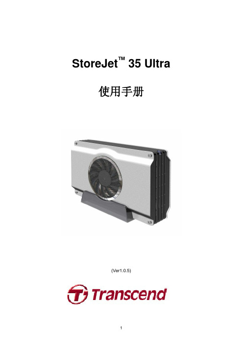
StoreJet™ 35 Ultra使用手册(Ver1.0.5)目录产品介绍︱ (3)包装内容︱ (3)产品特色︱ (4)系统需求︱ (4)安全注意事项︱ (5)一般使用 (5)设定 (5)资料备份 (5)电源 (5)提醒您 (5)产品概观︱ (6)安装硬盘︱ (7)将StoreJet 35 Ultra连接到计算机︱ (9)Windows®2000/XP (9)Windows Vista™ (10)Mac® OS (11)Linux® (11)安全删除StoreJet 35 Ultra︱ (12)Windows® 2000, XP and VISTA™ (USB) (12)Windows® 2000, XP and VISTA™ (eSATA) (12)Mac® OS (USB & eSATA) (14)Linux® Kernel 2.4或更新版本 (USB) (14)格式化硬盘︱ (15)Windows®2000/XP (15)Windows Vista™ (16)Mac® OS (18)Linux® (20)疑难排解︱ (21)疑难排解︱ (21)产品规格︱ (23)订购信息︱ (23)质保条款︱ (24)产品介绍︱感谢您购买创见StoreJet™ 35 Ultra硬盘外接盒。
本产品支持eSATA/USB2.0双接口规格,USB接口兼容于大多数的台式或笔记型计算机,eSATA接口则可提供每秒高达3.0Gb的传输速率,让硬盘效能达到极致。
此外,StoreJet 35 Ultra更配备超静音80mm 风扇,可有效降低硬盘过热的风险;本产品还附赠实用的备份软件,可进一步协助使用者提升工作效率*。
加装硬盘后,StoreJet 35 Ultra即成为绝佳的数据管理储存装置,可用来下载、储存、传输并备份宝贵的档案与数据。
西区MX-M350U复印机常用功能及使用方法
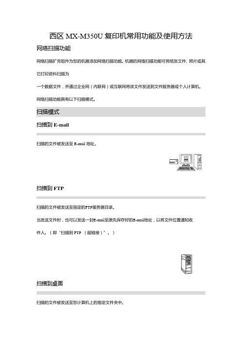
西区MX-M350U复印机常用功能及使用方法网络扫描功能网络扫描扩充组件为您的机器添加网络扫描功能。
机器的网络扫描功能可将纸张文件、照片或其它打印资料扫描为一个数据文件,并通过企业网(内联网)或互联网将该文件发送到文件服务器或个人计算机。
网络扫描功能具有以下扫描模式。
扫描模式扫描到E-mail扫描的文件被发送至E-mail地址。
扫描到FTP扫描的文件被发送至指定的FTP服务器目录。
当发送文件时,也可以发送一封E-mail至原先保存好的E-mail地址,以将文件位置通知收件人。
(即“扫描到FTP(超链接)”。
)扫描到桌面扫描的文件被发送至您计算机上的指定文件夹中。
使用扫描到桌面时,必须从网络扫描扩充组件附带的“Sharpdesk/网络扫描工具”光盘安装软件。
有关软件的系统要求,请参阅相应的手册(PDF格式)或光盘上的自述文件。
有关软件的安装步骤,请参阅“Sharpdesk安装向导”。
扫描到桌面功能只能在运行Windows 98第二版//Me/2000专业版/XP专业版/XP家庭版/Vista的计算机上使用。
扫描到网络文件夹扫描的文件被发送至机器所在网络上的某台Windows计算机的共享文件夹中。
可与安装有下列操作系统的计算机传输数据:Windows 98/Me/NT 4.0/2000/XP/Server2003/Vista网络扫描功能所需的设置要使用网络扫描功能,必须设置SMTP服务器、DNS服务器以及收件人地址。
要进行设置,需通过与机器处于同一网络的计算机来访问机器的网页。
可通过您的Web浏览器(Internet Explorer6.0或更高版本(Windows)、Netscape Navigator 7.0或更高版本)来显示该网页。
访问网页通过以下步骤访问网页。
1 在您的计算机上打开Web浏览器。
支持的浏览器:Internet Explorer 6.0或更高版本(Windows)Netscape Navigator 7.0或更高版本2在您的Web浏览器的“地址”栏上输入机器的IP地址。
ECS-100 (FW247) 系统硬件[1]
![ECS-100 (FW247) 系统硬件[1]](https://img.taocdn.com/s3/m/5bfca2f7fab069dc502201a5.png)
浙江中控技术股份有限公司ECS-100 系统硬件ECS-100 DCS系统培训培训内容 DCSDCS概述概述控制站硬件操作站硬件通讯网络第一部分第一部分::DCS DCS系统概述系统概述DCS:Distributed control system集散控制系统对象分散控制分散管理集中ECS-100硬件组成•控制站硬件•操作站硬件•通讯网络Advantrol PRO软件组成组态软件包•系统组态软件•流程图制作软件•报表制作软件•实时监控软件•图形化编程软件•……实时监控软件ECS-100系统整体构架ECS-100系统简介•系统名称系统名称::WebField ECS ECS--100DCS •WebField WebField ECS ECS :系列产品•100:系统型号第二部分:控制站硬件主要内容•机柜、机笼、供电•卡件----主控卡----数据转发卡----I/O卡件及端子板机柜、机笼、供电机柜•尺寸:2200×800×800•散热:风扇散热•内含工作接地铜条和保护接地铜条•拼装结构•防静电手腕机笼IO机笼电源机笼I/O机笼•内部固定有20条导轨,用于固定卡件每个槽位有具体的分工IO机笼安装电源指示卡保留位置FW235RJ45接口•IO 机笼连接IO 机笼IO机笼实例图电源系统冗余AC供电AC供电:即220V输入给电源模块。
220V A路220V B路冗余DC供电DC供电:即电源模块输出5V、24V给IO机笼供电。
控制站卡件Super-Man大脑功能: 思考、控制、管理神经功能: 信息传递感官、四肢功能: 感觉 、动作执行Super-Contorl大脑:主控卡功能: 管理\处理\控制\计算…神经:数据转发卡功能: 信号传递感官、四肢:I/O 卡功能: I/O 信号采集及控制控制站卡件摆放位置• 各类卡件在机笼中的摆放位置:接下来依次向大家介绍各类卡件。
主控制器主控制器(FW247 )•(1)面板指示灯FAIL RUN WORK STDBY LED LED--ALED LED--BSLAVE :故障报警或复位指示故障报警或复位指示;;:工作卡件运行指示工作卡件运行指示;;:工作工作//备用指示备用指示;;:准备就绪指示准备就绪指示,,备用卡件运行指示备用卡件运行指示;;:本卡件的通讯网络端口本卡件的通讯网络端口00的通讯状态指示灯的通讯状态指示灯;;:本卡件的通讯网络端口本卡件的通讯网络端口11的通讯状态指示灯的通讯状态指示灯;;:Slave CPU Slave CPU运行指示运行指示运行指示,,包括网络通信和包括网络通信和I/O I/O I/O采样运行指示采样运行指示采样运行指示。
光电 电容混合型光栅尺 AT353系列 539系列绝缘线性编码器说明书

SPECIFICATIONSScaleGraduation 20μmMaterialGlass, Thermal expansion coefficient:8x10⁻⁶/°CDetecting method Electrostatic capacitance/photoelectric type Mounting method FrameAccuracy (at 20°C)Up to 1500mm: (3+3L 0/1000)μm Over 1500mm: (5+5L 0/1000)μm Output signalAbsolute position serial data with FANUC NC formatEffective range 100 to 3000mm (20 models)Resolution0.05μmMax. response speed 2m/sec (120m/min)Supply current 250mA (max.)Power supplyDC5V (-3% to +5%)Operation temperature 0°C to 45°C Storage temperature-20°C to 70°CHigh-accuracy Real Absolute Sealed Linear Encoder for High-speed Motion!FEATURES•Hybrid real absolute glass scale with electrostatic capaci-tance/photoelectric technology.•No origin point restoration required.•0.05μm resolution.•Serial data output of Absolute position.•High response speed of 2m/sec (120m/min).•Direct connection with FANUC NC controller .•Good protection against harsh environment.APPLICATIONS•Position feedback for NC control.•NC system with linear motor .Specifications are subject to change without notice.Printed in Japan 61.009910 1 APRFM25828ISO 9002Mitutoyo Corporation20-1, Sakado 1-chome, Takatsu-ku, Kawasaki-shi,Kanagawa 213-0012, JapanPhone (044)813-8230 Fax (044)813-8231http://www.mitutoyo.co.jpMODEL AT3530.2GA0.1A Head cable (5m)(Flexible metallic tube)Air intake (M5)(at both ends)Scale unit mounting surfaceDetecting head mounting surface(Adjustable)Mounting block (Fixed)Countersunk,depth 6.5C o u n t e r s u n k ,d e p t h 5View from X directionXC 1(φ16)(42)φ10.5(46.3)41.2(0.5)11 (h e x .)1.5±0.22995.532.5231512.6811.6777Overall length L28060±0.2Maximum travel length L19060±0.2Effective measuring length L0Middle support position L3Middle support interval L41.5±0.2361550.57.566±0.32-φ8Countersunk,depth 6.5(Fixed)G0.2G0.2Effective measuring length L060±0.2Maximum travel length L160±0.280Middle support position L3Overall length L277711.6812.6151.5±0.22.5(0.5)(42)(φ16)90Middle support interval L4Middle support interval L47.566±0.32-φ8MODEL AT353G: Machine guide wayMounting block(Adjustable)(Adjustable)Detecting head mounting surface Scale unitmounting surfaceDimensionsUnit: mm (inch)Unit: mm AT353L0L1L2L3L4B -100100120230651002-150150170280651502-200200220330652002-250250270380652502-3003003304402201503-3503503804902451753-4004004305402702003-4504504805902952253-5005005406503252503-6006006507603803003-7007007608704353503-7507508109204603753-8008008609704854003-90090096010705354503-10001000106011705855003-11001100116012706352755-12001200126013706853005-13001300136014707353255-14001400146015707853505-15001500156016708353755-16001600169018009004005-17001700179019009504255-180018001890200010004505-200020002100221011053357-220022002300241012053707-240024002500261013054007-250025002600271013553159-260026002700281014053259-280028002900301015053509-300030003050321016053759L0:Effective measuring length L1:Maximum travel length L2:Overall lengthL3:Middle support position L4:Middle support interval B:Number of mounting blockRefer to the details on the back page.。
ecs100
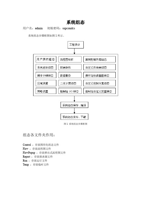
系统组态用户名:admin 初始密码:supcondcs系统组态步骤框图如图1所示。
图1 系统组态步骤框图组态各文件夹作用:Control :存放图形化组态文件Flow :存放流程图文件FlowPopup :存放弹出式流程图文件Report :存放报表源文件Run :存放运行文件Temp :存放临时文件主机设置主控制卡注释:CS1 / CS2(可为任意字符),注释长度为20个字符。
IP地址:组态时确保所填写的IP地址与实际硬件的IP地址一致。
单个区域网中最多可组63个控制站。
(默认地址:128.128.1.2 最后一位必须是偶数)表1 TCP/IP协议控制站地址的系统约定周期:其值必须为0.05秒的整数倍类型:类型一栏有控制站、采集站和逻辑站三种选项型号:可以根据需要从下拉列表中选择不同的型号,如FW243L、FW247等。
通讯:数据通讯过程中要遵守的协议。
目前通讯采用UDP用户数据包协议。
UDP 协议是TCP/IP协议的一种,具有通讯速度快的特点。
冗余:打勾代表当前主控制卡设为冗余工作方式,不打勾代表当前主控制卡设为单卡工作方式。
单击冗余选项将自动打勾,再次单击将取消打勾。
单卡工作方式下在偶数地址放置主控制卡,冗余工作方式下,其相邻的奇数地址自动被分配给冗余的主控制卡,不需要再次设置。
网线:选择需要使用的网络A、网络B或者冗余网络进行通讯。
每块主控制卡都具有两个通信口,在上的通讯口称为网络A,在下的通讯口称为网络B,当两个通讯口同时被使用时称为冗余网络通讯。
冷端:选择热电偶的冷端补偿方式,可以选择就地或远程。
就地:表示通过热电偶卡(或热敏电阻)采集温度进行冷端补偿。
远程:表示统一从数据转发卡上读取温度进行冷端补偿。
操作站注释:可以写入相关的文字说明(可为任意字符),注释长度为20个字符。
IP地址:最多可组72个操作站,对TCP/IP协议地址采用表2所示的系统约定。
表2 SCnet II操作站地址约定类型:操作站类型分为工程师站、数据站和操作站三种工程师站:128.128.1.130 (一个)操作站:128.128.131.。
EM 3532-U RF 无线系统 3000系列接收器一般特征说明书
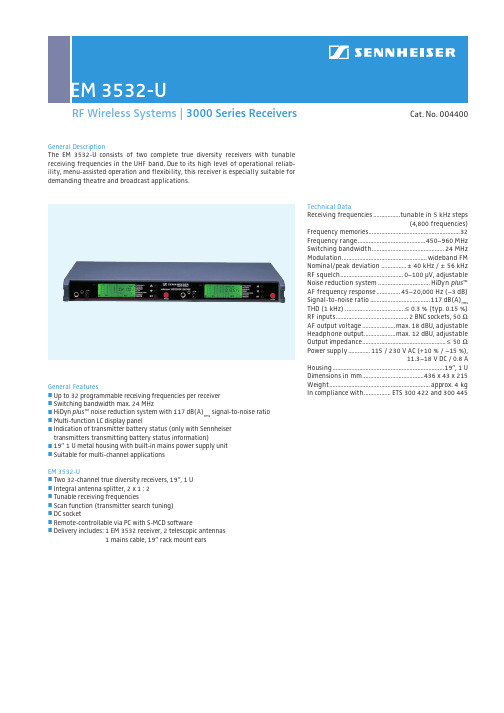
RF Wireless Systems | 3000 Series ReceiversGeneral Featuresj Up to 32 programmable receiving frequencies per receiver j Switching bandwidth max. 24 MHzj HiDyn plus ™ noise reduction system with 117 dB(A)rms signal-to-noise ratio j Multi-function LC display panel j I ndication of transmitter battery status (only with Sennheiser transmitters transmitting battery status information)j 19” 1 U metal housing with built-in mains power supply unit j Suitable for multi-channel applicationsEM 3532-Uj Two 32-channel true diversity receivers, 19”, 1 U j Integral antenna splitter, 2 x 1 : 2j Tunable receiving frequenciesj Scan function (transmitter search tuning)j DC socketj Remote-controllable via PC with S-MCD software j Delivery includes: 1 EM 3532 receiver, 2 telescopic antennas1 mains cable, 19” rack mount earsGeneral DescriptionThe EM 3532-U consists of two complete true diversity receivers with tunable receiving frequencies in the UHF band. Due to its high level of operational reliab-ility, menu-assisted operation and flexibility, this receiver is especially suitable for demanding theatre and broadcast applications.Technical DataReceiving frequencies.................tunable in 5 kHz steps(4,800 frequencies)Frequency memories..........................................................32Frequency range...........................................450–960 MHz Switching bandwidth..............................................24 MHz Modulation......................................................wideband FM Nominal/peak deviation ................± 40 kHz / ± 56 kHz RF squelch........................................0–100 µV, adjustable Noise reduction system.................................HiDyn plus ™AF frequency response...............45–20,000 Hz (–3 dB)Signal-to-noise ratio......................................117 dB(A)rms THD (1 kHz)......................................≤ 0.3 % (typ. 0.15 %)RF inputs..............................................2 BNC sockets, 50 ΩAF output voltage.....................max. 18 dBU, adjustable Headphone output....................max. 12 dBU, adjustable Output impedance.....................................................≤ 50 ΩPower supply..............115 / 230 V AC (+10 % / –15 %),11.3–18 V DC / 0.8 AHousing.......................................................................19”, 1 U Dimensions in mm.......................................436 x 43 x 215 Weight................................................................approx. 4 kg In compliance with.................ETS 300 422 and 300 445Cat. No. 004400RF Wireless Systems | 3000 Series ReceiversEM 3532 dimensionsAccessories for EM 3532j G A 3030 AM antenna mount Cat. No. 004368 j A 12 AD UHF active directional antenna Cat. No. 004156 j A 1031-U passive omni-directional antenna Cat. No. 004645 j G ZA 1036-9 ground plane antenna Cat. No. 002336 j N/BNC adaptor Cat. No. 033839 j R G 58 co-axial antenna cableGZL 1019 A1 (1 m) Cat. No. 002324 GZL 1019 A5 (5 m) Cat. No. 002325 GZL 1019 A10 (10 m) Cat. No. 002326 j G ZV 1019A BNC coupler Cat. No. 002368 j S-MCD 3000-HP Mikroport Computer Display Cat. No. 004617 j K X 3500.S-MCD RX/RX connection cable Cat. No. 004619 j R X/PC connection cable (please specify length when ordering) Cat. No. 075525 j A SA 3000-EU active antenna splitter Cat. No. 009423 j A SA 3000-UK Cat. No. 008408 j A SA 3000-US Cat. No. 009407RF Wireless Systems | 3000 Series ReceiversEM 3532-U Array The EM 3532-U consists of two complete true diversity receivers in a 19” housing.The EM 3532-U has been specially designed for demanding theatre and broadcastapplications; it is fully suitable for multi-channel applications and can be usedwith any UHF transmitter of the 3000, and 5000 series.Each receiver of the EM 3532-U has 32 frequency memories to store up to 32 fre -quencies with their respective channel numbers. The frequencies are tunable in 5 kHzsteps within a switching bandwidth of 24 MHz max. (i.e., each receiver has 4,800freely selectable frequencies), so that, if a frequency has interference or is over-loaded, you can simply switch to a different frequency.The EM 3532-U is very flexible and reliable due to its menu-assisted operation. It isalso extremely easy to use: via the operating menu you can select and store receiv-ing frequencies, select channel numbers and assign them to the receiving frequen-cies, adjust the RF squelch, activate and deactivate the scan function (transmittersearch tuning), and switch on and off the booster supply voltage.The multi-functional LC display shows either the selected receiving frequency or theallocated channel number. On the display, two bargraphs represent the received RFsignal (“RF”) and the deviation of the AF signal (“DEV”). Furthermore – and pro-vided that a Sennheiser transmitter transmitting a battery status signal is used – thetransmitter battery/accupack status is indicated in %. A flashing “LOW BATT” dis-play indicates that there are about 20 to 30 minutes of operation left. In addition,the display shows the currently selected menu and all possible settings.The EM 3532-U features a scan function (transmitter search tuning) for scanningthe frequency range for field strength levels. If a transmitter with a sufficientfield strength (at least 5 µV) is found, this frequency is automatically shown onthe display and can then be stored. For complex multi-channel applications, werecommend controlling the receivers via a PC using the matching S-MCD software.Reading off the LC displayEM 3532 front panel operating controlsYou can use the S-MCD to manage and control up to 126 EM 3532-U and EM 1046 receivers. The EM 3532 receivers are coupled in series by means of data cables and are subsequently connected to the PC via an RS 485 interface — additional inter-face modules are not required. The EM 1046 receivers are connected to the parallel interface of the PC via the EM 1046 DI display interface. For detailed information of the installation of the EM 1046 receivers, please refer to the chapter ”5000 Series Receiver Systems“.Using S-MCD you can program entire sequences of scenes with several actors without having to change the transmitter/receiver unit. Each actor keeps his or her transmitter and can be switched in when necessary. During operation you can monitor battery status, volume level, and transmission frequency. If necessary, you can switch to another frequency.The “Receiver Configuration” window (see fig. 3) offers about the same displays and menus that are also directly available on the receiver. The “RF” and “Dev” bargraphs provide information on RF and AF levels. The “Batt” bargraph indicates the battery status. With the “Squelch” control, you can determine the operating thresh o ld for the RF squelch. The frequency list shows the frequencies and their allocated channel numbers.By clicking the “Scan up” and “Scan down” buttons, the EM 3532‘s scan function is activated. If a frequency is found, it is displayed in the frequency list.The RF recorder menu offers two operating modes. In the “RF Level Recorder” mode you can record measuring values over a certain period of time. In the “RF Spectrum Analyzer” mode (EM 3532 only) (see fig. 4) you can record measu-ring data of a defined frequency range.RF Wireless Systems | 3000 Series ReceiversEM 3532 back panel featuresFig. 1: Display of a scene configuration with many actors on the S-MCD Mikroport computer displayFig. 2: Display of a scene configuration with four actors on the S-MCD Mikroport computer displayFig. 3: Window “Receiver Configuration”Fig. 4: Window “RF Recorder”, “RF Spectrum Analyzer”。
浙江中控ECS-100系统硬件介绍

冗余
TB352-RU
8
配套端子板 TB352-U
◆16 路端子板,供2块不冗余FW352用。
端子板上有冷端补偿电路,可对冷端温度进行补偿。
配套端子板 TB352-RU
◆8 路端子板,供2块冗余FW352用。
端子板上有冷端补偿电路,可对冷端温度进行补偿。
热电阻信号输入卡
热电阻信号输入卡
• FW353
数据转发卡
冗余配置: 单卡配置:
IO卡及端子板
IO卡及端子板
IO卡及端子板
IO卡
系统信号线缆
端子板
现场信号
IO卡及端子板
•(1)信号类型
按状态分:
模拟量(Analog) :随时间连续变化信号(如电压,电流等信号) ;
数字量(Digital):0、1表示通断 (ON\OFF),可称开关量;
单卡
TB351-IU
16
电流
冗余
TB351-IRU
8
配电:向现场变送器输出 24V 配电时必须安装配电模块PM-351I
PM-351I
配套端子板 TB351-IU
◆16路端子板,供2块不冗余FW351使用。
DB 1
DB2
J4
73
76
2 J1 1
32 34 J3 40 42 31 33 39 41
J2
72 71
配套端子板 TB351-IRU
◆8 路端子板,供2块冗余FW351使用。
热电偶信号输入卡
热电偶信号输入卡
• FW352(B)
性能说明:
信号类型:
-20~+20 /-100~+100mV
各类热电偶(E/J/K/S/T等) 测量精度:±0.2%FS
TB353-U使用手册
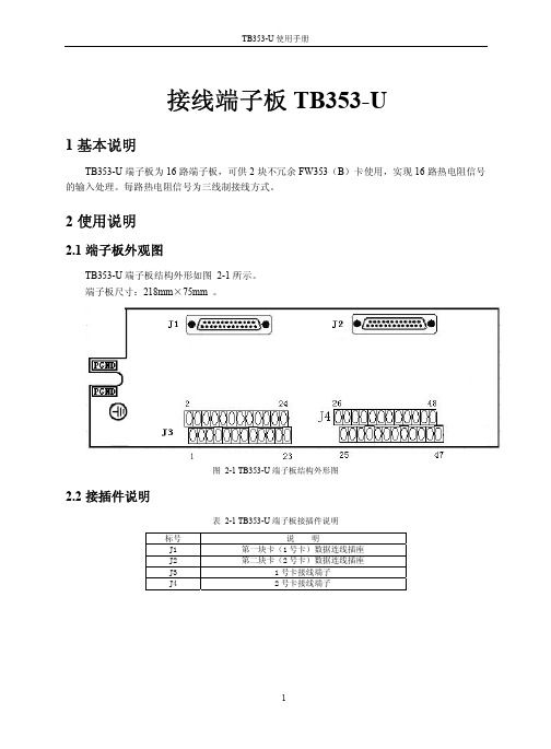
接线端子板TB353-U1基本说明TB353-U端子板为16路端子板,可供2块不冗余FW353(B)卡使用,实现16路热电阻信号的输入处理。
每路热电阻信号为三线制接线方式。
2使用说明2.1端子板外观图TB353-U端子板结构外形如图 2-1所示。
端子板尺寸:218mm×75mm 。
图 2-1 TB353-U端子板结构外形图2.2接插件说明表 2-1 TB353-U端子板接插件说明标号 说 明J1 第一块卡(1号卡)数据连线插座J2 第二块卡(2号卡)数据连线插座J3 1号卡接线端子J4 2号卡接线端子2.3 接口特性图 2-2接口特性图2.4 端子定义及接线TB353-U 接线说明如表 2-2所示。
每路热电阻信号为三线制接线方式,热电阻的三个接点分别描述为A 、B 、C 。
例如把一个热电阻信号接到FW353(B )卡的第一通道上,那么TB353-U 端子板接线端子1连接A 、端子2连接B 、端子3连接C 。
表 2-2 接线说明卡号接线图信号端子接线 通道1(CH1)1 2 3 A B C通道2(CH2)4 5 6 A B C通道3(CH3)7 8 9 A B C通道4(CH4)10 11 12 A B C通道5(CH5)13 14 15 A B C通道6(CH6)16 17 18 A B C通道7(CH7)19 20 21 A B C通道8(CH8)22 23 24 一 号 卡A B C通道9(CH9)25 26 27A B C通道10(CH10)28 29 30A B C通道11(CH11)31 32 33A B C通道12(CH12)34 35 36A B C通道13(CH13)37 38 39A B C通道14(CH14)40 41 42A B C通道15(CH15)43 44 45A B C通道16(CH16)46 47 48二号卡A B C 3资料版本说明表 3-1版本升级更改一览表资料版本号输出时间更改说明TB353-U使用手册(V1.0)2009-05-22适用模块版本:TB353-U-11.00.00。
集散控制系统报告
集散控制系统报告——WebField ECS —100 系统信息工程学院 电子信息工程11402班 沈丽娜 19号WebField ECS-100——采用新型的WEB 化体系结构,突破了传统控制系统的层次模型,实现了多种总线兼容和异构系统综合集成的“网络化现场智能控制系统”。
该系统融合了最新的现场总线技术、嵌入式软件技术、先进控制技术与网络技术,各种国内外DCS 、PLC 及现场智能设备都可以接入到ECS-100系统中,实现企业内过程控制设备信息的共享。
ECS-100控制系统简化了工业自动化的体系结构,增强了过程控制的功能和效率,提高了工业自动化的整体性和稳定性,最终使企业节省了为工业自动化而做出的投资,真正体现了工业基础自动化的开放性精神,使自动化系统实现了网络化、智能化、数字化,突破了传统DCS 、PLC 等控制系统的概念和功能,也实现了企业内过程控制、设备管理的合理统一。
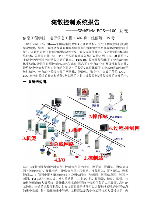
一 系统结构图:ECS-100控制系统由控制节点(控制节点是控制站、数采站、逻辑站、通信接口网关等的统称)、操作节点(操作节点是工程师站、操作员站、服务器站、数据管理站、时间同步服务器等的统称)及通信网络(管理网、过程信息网、过程控制网、I/O 总线)等构成。
操作员站是由工业PC 机、显示器、键盘、鼠标、打印机等组成的人机系统,是操作人员完成过程监控管理任务的人机界面。
高性能工控机、卓越的流程图机能、多窗口画面显示功能可以方便地实现生产过程信息的集中显示、集中操作和集中管理。
工程师站是为专业工程技术人员设计的,内6.过程控制网络7.操作站1.机柜5.总线网络 3.机笼4.I /O2.控制站装有相应的组态平台、监控平台和系统维护工具。
通过系统组态平台构建适合于生产工艺要求的应用系统,具体功能包括:系统生成、数据库结构定义、操作组态、流程图画面组态、报表制作等;通过监控平台可替代操作员站,实现生产过程的实时监控。
而使用系统的维护工具软件可实现过程控制网络调试、故障诊断、信号调校等。
中控-Webfield-ECS-100新部件目录-751
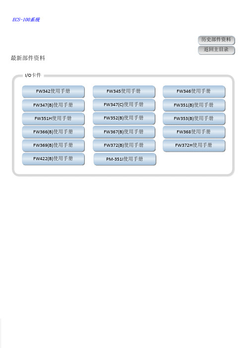
FW342使用手册FW347(C)使用手册FW352(B)使用手册FW367(B)使用手册FW372(B)使用手册PM-351I使用手册FW347(B)使用手册FW351H使用手册FW366(B)使用手册FW369(B)使用手册FW422(B)使用手册FW346使用手册FW351(B)使用手册FW353(B)使用手册FW368使用手册FW372H使用手册FW345使用手册I/O卡件最新部件资料TB241-U使用手册TB242-U使用手册TB346使用手册TB351-IU 使用手册TB342-U 使用手册TB347使用手册TB351-VRU 使用手册TB248-RU 使用手册TB345使用手册TB351-IRU 使用手册TB351-VU 使用手册TB352-RU 使用手册TB352-U 使用手册TB353-U 使用手册TB359-E8R 使用手册TB366-DU 使用手册TB353-RU 使用手册TB366-GPRHU 使用手册TB366-E8R 使用手册TB366-220VU 使用手册TB366-GPRU 使用手册TB366-NPNU 使用手册TB366-48VU 使用手册TB366-DRU 使用手册TB367-DU 使用手册TB367-DRU 使用手册端子板最新部件资料TB372-E8R 使用手册TB367-GPRPU 使用手册TB367-GPRU 使用手册TB367-E8R 使用手册TB368-U 使用手册TB372-RU 使用手册TB367R-GPR 使用手册TB372-U 使用手册TB561使用手册TB564使用手册TB563使用手册TU001-R 使用手册TU031-I0000使用手册CN011使用手册FW233使用手册FW246X 使用手册FW212使用手册FW214使用手册FW235使用手册FW248R使用手册FW221使用手册FW243X使用手册FW247(B)使用手册FW252-03A, 04A, 05使用手册FW253使用手册TB252使用手册TB261使用手册CN032-S30使用手册控制站部件最新部件资料SP433M/FW433M 使用手册网络部件历史部件资料返回主目录F-02M&F-20S 使用手册SUP-2119M 使用手册SP433M/FW433M 使用手册网络部件OP032使用手册操作站部件OP036使用手册OP075使用手册PW021使用手册平面式操作台使用手册PW031-S11使用手册PROFIBUS-DP 通信模块使用手册特殊模块SUP-5117M 使用手册FW433S 使用手册。
FW353(B)使用手册
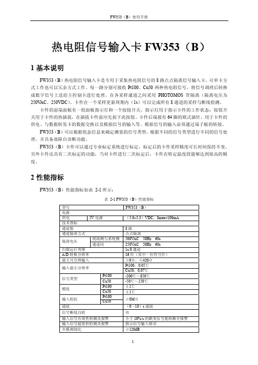
热电阻信号输入卡FW353(B)1基本说明FW353(B)热电阻信号输入卡是专用于采集热电阻信号的8路点点隔离信号输入卡,可单卡方式工作也可以冗余方式工作。
每一路分别可接收Pt100、Cu50两种热电阻信号,将信号调理后转换成数字信号上送给主控制卡进行处理。
在各采样通道之间采用PHOTOMOS管隔离(隔离电压为250V AC、250VDC)。
卡件在一个采样更新周期内(1s)可以完成所有8通道的采样与断线检测。
卡件的前端面板有一组面板指示灯和一个按钮开关。
指示灯用于指示卡件的工作状态;按钮开关用于卡件的热插拔,在插拔卡件前应先按下此按钮。
卡件后端接有64脚的欧式插针,用于卡件的供电、与数据转发卡的数据交换以及模拟信号的输入等。
模拟信号的输入必须通过端子板的转接。
FW353(B)可以根据组态信息来确定测量的信号类型,根据不同的信号类型进行不同的信号处理,并具备故障自诊断功能。
FW353(B)卡件可以通过专业标定系统进行标定,标定后的卡件采样精度可长时间保持不变。
另外卡件还具有二次标定的功能,当对卡件进行二次标定后,卡件在特定温度段能够达到很高的精度。
2性能指标FW353(B)性能指标如表 2-1所示:表 2-1 FW353(B)性能指标型号 FW353(B)电源供电 5V电源(5.0~5.3)VDC,Imax<100mA技术指标通道数8路通道隔离方式点点隔离现场侧与系统侧500V AC 50Hz 60s隔离电压通道间250V AC 50Hz 60s扫描运行周期 1s/8通道A/D转换分辨率 16位(其中一位符号位)最大可分辨输入≥0Ω,≤420ΩPt100,0.05℃输入最小分辨率Cu50,0.07℃Pt100 -200℃~850℃信号类型Cu50 -50℃~150℃Pt100 ±1℃精度Cu50 ±1℃Pt100≥8MΩ输入阻抗Cu50滤波(0~10)s滤波信号断线自检有输入信号有效性检测及报警小于10%/s的跳变信号能检测并报警输入信号超量程检测及报警指示信号输入错误共模抑制比≥120dB串模抑制比≥60dBEMC指标抗电快速脉冲群干扰信号线与地1kV抗浪涌冲击干扰信号线与地2kV抗射频电磁波干扰10V/m抗静电放电干扰空气放电8kV,接触放电6kV其它工作温度(0~50)℃工作湿度(10~90)%,无凝露存储和运输温度(-40~+80)℃存储湿度(5~95)%,无凝露工作大气压(62~106)kPA3接口特性FW353(B)接口特性图如图 3-1所示。
ISA-353G线路光纤纵差保护测控装置技术使用说明书V3.11-070101[1]
![ISA-353G线路光纤纵差保护测控装置技术使用说明书V3.11-070101[1]](https://img.taocdn.com/s3/m/417553110b4e767f5acfce45.png)
3.4
3.4.1
本装置提供三段式过流保护,即“瞬时电流速断保护”、“限时电流速断保护”和“定时限过流保护”。各段保护均可选择带低压闭锁和方向环节,各段保护的电流、时间定值均可独立整定。
图3-4-1低压闭锁方向限时电流速断保护逻辑图
2)断路器在“合后”状态(HHJ= 1)
3)断路器合位(TWJ = 0,HWJ=1)
启动条件
1)重合闸已“充电”
2)断路器出现不对应状态(TWJ=1,HWJ=0,HHJ=1)
3)三相无流
图3-5-1三相一次重合闸逻辑图
3.6
1)本装置采用分散分布式低周减载方案,设滑差闭锁和无滑差闭锁两段,两段可独立投退,其频率定值及动作时限可单独整定。
交流电流回路:IN=5A,每相不大于1VA
IN=1A,每相不大于0.5VA
IN=0.3A,每相不大于0.5VA
直流电源回路:正常工作时,不大于15W
保护动作时,不大于25W
保护回路过载能力:
交流电压回路:1.2倍额定电压,连续工作
交流电流回路:2倍额定电流,连续工作
10倍额定电流,允许10s
40倍额定电流,允许1s
2)分相电流纵差保护的动作受本相稳态过量判据闭锁,以增加差动继电器本身的安全性,其过量电流门槛值为0.06In。当保护的一侧是无电源的负荷侧时,区内三相故障时,可能无故障电流,为确保负荷侧能正确跳闸,则应将“弱馈侧投退”(d497)设为投入,这种情况下,本侧即使无故障电流,也能可靠跳闸,同时也保证对侧装置能够可靠跳闸。
3.4.3
本装置配置了独立的后加速段保护,作为充电保护使用。后加速段有效时间为3s,即在断路器由跳位变合位的3s时间内无论手合或自动重合闸,后加速保护均有效。后加速保护应躲过线路所带用户变压器的励磁涌流。
M-System 53U 多功能电力监测仪说明书
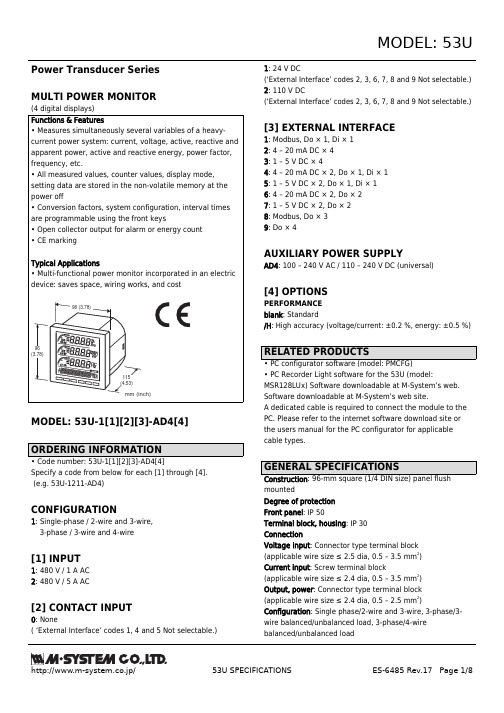
Power Transducer Series MULTI POWER MONITORMODEL: 53U-1[1][2][3]-AD4[4]Specify a code from below for each [1] through [4]. (e.g. 53U-1211-AD4)CONFIGURATION1: Single-phase / 2-wire and 3-wire, 3-phase / 3-wire and 4-wire[1] INPUT1: 480 V / 1 A AC 2: 480 V / 5 A AC[2] CONTACT INPUT0: None( ‘External Interface’ codes 1, 4 and 5 Not selectable.)1: 24 V DC(‘External Interface’ codes 2, 3, 6, 7, 8 and 9 Not selectable.)2: 110 V DC(‘External Interface’ codes 2, 3, 6, 7, 8 and 9 Not selectable.)[3] EXTERNAL INTERFACE1: Modbus, Do × 1, Di × 12: 4 – 20 mA DC × 43: 1 – 5 V DC × 44: 4 – 20 mA DC × 2, Do × 1, Di × 15: 1 – 5 V DC × 2, Do × 1, Di × 16: 4 – 20 mA DC × 2, Do × 27: 1 – 5 V DC × 2, Do × 28: Modbus, Do × 39: Do × 4AUXILIARY POWER SUPPLYAD4: 100 – 240 V AC / 110 – 240 V DC (universal)[4] OPTIONSPERFORMANCE blank : Standard/H : High accuracy (voltage/current: ±0.2 %, energy: ±0.5 %)• PC Recorder Light software for the 53U (model:MSR128LUx) Software downloadable at M-System’s web.Software downloadable at M-System’s web site.A dedicated cable is required to connect the module to the PC. Please refer to the internet software download site or the users manual for the PC configurator for applicable cable types.mountedDegree of protection Front panel : IP 50Terminal block, housing : IP 30ConnectionVoltage input : Connector type terminal block (applicable wire size ≤ 2.5 dia, 0.5 – 3.5 mm 2)Current input : Screw terminal block(applicable wire size ≤ 2.4 dia, 0.5 – 3.5 mm 2)Output, power : Connector type terminal block (applicable wire size ≤ 2.4 dia, 0.5 – 2.5 mm 2)Configuration : Single phase/2-wire and 3-wire, 3-phase/3-wire balanced/unbalanced load, 3-phase/4-wire balanced/unbalanced loadHousing material : Flame-resistant resin (gray)Isolation : Voltage input to current input to contact input to network interface or configurator jack or analog output to contact output (between each contact output except for External Interface code 8) to power • Measured variablesVoltage : 1 – N, 2 – N, 3 – N, 1 – 2, 2 – 3, 3 – 1Current : 1, 2, 3, NAverage current : 1, 2, 3Active / reactive / apparent power : 1, 2, 3, ΣPower factor : 1, 2, 3, ΣFrequencyPhase angle between voltages : 1 - 2, 2 - 3, 3 - 1Active energy incoming / outgoing : ΣReactive energy inductive / capacitive : ΣApparent energy : ΣActive / reactive / apparent power intervals (demand)Other demandsHarmonic contents : 2nd to 31st Max. and min. values■ DISPLAY : LCD with LED backlight (LED OFF timer available)Signed : 4 digits, 3 lines Energy : 9 digits, 1 line Bargraph : 3 points• Voltage Input Rated voltageLine-to-line (delta voltage): 480 V Line-neutral (phase voltage): 277 VConsumption VA : ≤ U LN 2 / 300 kΩ / phaseOverload capacity : 200 % of rating for 10 sec., 120%continuousSelectable primary voltage range : 50 – 400 000 V • Current InputRated current : 1 A or 5 AConsumption VA : ≤ I 2 · 0.01 Ω / phaseOverload capacity : 4000 % of rating for 1 sec., 2000% for 4sec., 120% continuousSelectable primary current range : 1 – 20 000 A Operational rangeVoltage, current, apparent power : ≤ 120 % of the rating Active/reactive power : ≤ ±120 % of the rating Frequency : 45 – 65 Hz Power factor : ≤ ±1• Contact Input : 24 V DC or 110 V DC (input resistance 6 kΩ)Detecting voltage : External 24 V DC ±10 % or 110 V DC ±10 %ON current : ≥ 1 mA (≤ 24 kΩ @ 24 V, ≤ 110 kΩ @110 V)OFF current : ≤ 0.1 mA (≥ 240 kΩ @ 24 V, ≥ 1.1 MΩ @ 110V)Detecting time : 10 – 1000 msec.The status can be monitored on the Modbus; usable to reset energy count or to update average (demand) value.Transmission : Half-duplex, asynchronous, no procedure Interface : Conforms to EIA RS-485Max. transmission distance : 500 meters Baud rate : 1.2 – 38.4 kbpsMax. number of nodes : 31 (except the master)Protocol : Modbus RTUMedia : Shielded twisted-pair cable (CPEV-S 0.9 dia.)• DC Current Output : 4 – 20 mA DC Load resistance : ≤ 270 ΩMeasurands converted into analog output : Voltage, Current,Active / reactive / apparent power, Power factor, Frequency,Harmonic contents• DC Voltage Output : 1 – 5 V DC Load resistance : ≥ 5000 ΩMeasurands converted into analog output : Voltage, Current,Active / reactive / apparent power, Power factor, Frequency,Harmonic contents • OPEN COLLECTORProgrammable for either alarm or energy count.Max. rated load : 130 V DC @50 mAContinuous rated load : 130 V DC @30 mA Saturation voltage : 1.5 V DCMeasurands applicable to alarm : Voltage, current, current intervals, neutral current, frequency, energy, energy intervals(ON delay, deadband and other parameters are selectable)Measurands applicable to count : Energy;Pulse rate selectable within0.1 – 10 000.0 kWh/p, kvarh/p, kVAh/p•AC : Operational voltage range 85 – 264 V 47 – 66 Hz; < 8 VA•DC : Operational voltage range 99 – 264 V < 4 W; ripple 10 % p-p max.Operating temperature : -10 to +55°C (14 to 131°F)Storage temperature : -20 to +80°C (-4 to +176°F)Operating humidity: 90 % RH max. (non-condensing)Mounting : Panel flush mounting Weight : 300 g (0.66 lbs)Voltage: ±0.3 % (±0.2 % for Option /H)*Current: ±0.3 % (±0.2 % for Option /H)*Power: ±0.5 %*Power factor: ±0.5 %Frequency: ±0.1 %*Energy: ±1 % (±0.5 % for Option /H)Harmonic contents: ±1 %*Analog output: Accuracy of assigned measurand or ±0.2 %,whichever is greater.* In percentage of the spans: 480 V for voltage, 1 A or 5 Afor current, 4155 W (5 A) or 831 W (1 A) for active power.The described accuracy levels are ensured at the input 1 %or more for phase 2 current with 3-phase/3-wire unbalancedload, for neutral current with 3-phase/4-wire unbalancedload, and neutral current with 1-phase/3-wire.Response time: ≤ 2 sec. (0 – 99 %),≤ 3 sec. for frequency and harmonic contentsSampling time:Harmonic contents and frequency: ≤ 1.1 sec.Other: ≤ 600 msec.Insulation resistance: ≥ 100 MΩ with 500 V DC(voltage input to current input to contact input to networkinterface or configurator jack or analog output to contactoutput to power)Between each contact output except for External Interfacecode 8.Dielectric strength:4000 V AC @1 minute(voltage input or current input or contact input or contactoutput or network interface or configurator jack or analogoutput to power)2500 V AC @1 minute(voltage input to current input to contact input to contactoutput to network interface or configurator jack or analogoutput)2000 V AC @1 minute(between each contact output except for External Interfacecode 8)2000 V AC @1 minute (circuits to housing)EMC Directive (2004/108/EC)EN 61000-6-4 (EMI)EN 61000-6-2 (EMS)Low Voltage Directive (2006/95/EC)EN 61010-1Installation Category IIIPollution Degree 2IEC standard: IEC 62053-22 class 0.5sIEC 62053-23 class 2(IEC standards are applicable with Option /H only)+.8(3.65)+0.8 (3.65)Panel thickness : 2 to 15 mm (0.08 to 0.59 inch)Configurator JackExternal InterfaceDO/PO +–DI+–T1T2T3T4InputV1V2V3N 1S 1L 2S 2L 3S 3LPower InputU (+)V (–)CONFIG• Contact Input Connection E.g.• Contact Output Connection E.g.To otherModbus devices s EXTERNAL INTERFACE CODE: 1When the device is located at the end of a transmission line viatwisted-pair cable, (when there is no cross-wiring), close across the terminal T2 – T3 with a leadwire.When the device is not at the end, no shortcircuit wire is required.Analog output may momentarily fluctuate while the configurator cableis left connected.*1.*2.s EXTERNAL INTERFACE CODE: 8s EXTERNAL INTERFACE CODE: 4, 5s EXTERNAL INTERFACE CODE: 6, 7s EXTERNAL INTERFACE CODE: 9s EXTERNAL INTERFACE CODE: 2*2*2*21*1. Internal terminating resistor is used when the device is at the end of a transmission line.*2. Install shield cables to all sections and ground them at single point.s RS-485 / RS-232C*1Multi Power Monitor(model: 53U)s RS-485 / ETHERNET*1(model: 53U)*1. Insert lightning surge protectors recommended in this example if necessary.。
Kushlan Products 350DD Epoxy 操作说明书和部件手册

Operating Instruction andParts Manual for350DD Epoxy12010 Dairy Ashford Road, Suite 160Sugar Land, TX 77478281-313-2506 • 800-469-4178W ARNINGDO NOT ATTEMPT TO START OR OPERATE THE MACHINE UNTIL ALL THE INSTRUCTIONS HAVE BEEN READ AND UNDERSTOOD BY THE OPERATOR.FAILURE TO DO SO COULD RESULT IN SERIOUS BODILY INJURY AND/ OR PROPERTY DAMAGE!•After referring to the operation manual, if assistance is still needed, please consult our web Site at • From our web site you may e-mail us directly If assistance is still required, please call our customer service department at 1-800-469-4178Safety Alert Symbol: This safety alert symbol is used to attract your attention!• Personal Safety is involved when you see this symbol, Pay extra attention, become alert-be sure to heed it’s message. Failure to do so may lead to serious personal injury or damage may occur.• Warnings and safety instruction: If these warnings and safety instructions are not read and carefully followed, serious personal injury could occur.WARNINGS1. Do not use, start, or attempt to operate this machine until all of the instructions have been read and fully understood.2. Never allow anyone to operate this machine unless the person is well acquainted with these rules of safe operation.3. Never operate this machine without all guards in place and firmly attached to the machine.4. Make certain that the mixing drum is clear of obstructions and stand clear of the machine with out all guards in place and firmly attached to the machine.5. When cleaning, lubricating, or adjusting the mixer, disconnect the power plug.6. Keep all people (except operator) a minimum of five (5) feet away from the machine during operation.7. Always make certain that the mixer is connected to a properly grounded electric circuit to protect the operator from possible electric shock.8. Do not start the engine if the drum is Fully loaded 9. Do not overload the mixer10. Never attempt to move the mixer while the engine is on.SHOULD YOU REQUIRE ANYSET-UP OR OPERATING ASSISTANCE WITH YOUR PRODUCT,2. Do not operate this machine under the influence of alcohol or while taking medication that impairs the senses or reactions.3. Make certain that the work area around the machine is clear of debris and obstructions.4. Keep all unauthorized and untrained people away from the machine at all times.5. Never let the mixer run unattended even for a brief moment.6. Turn off the engine when you leave the machine.7. Only use or operate the mixer on level ground to prevent the mixer from tipping over.8. Do not overreach while working with the mixer. Keep proper Footing and balance at all times when loading or unloading the mixer.9. Never allow children or inexperienced operators to operate or repair the mixer.10. Use only factory authorized parts for replacement11. Keep these operation instructions with the machine at all times12. Always wear safety glasses and safety shoes when operating and moving equipment 13. Safety decals – replace missing damaged safety decals.bushings. LUBRICATE ALL FITTINGS BEFORE EACH USEB. GEARBOX MOTOR: Mixer shipped with lubricate/oil in gearbox. Change lubricate/oil every 200 hours. Use 10 ounces of Synthetic Mobile 1 LS 75W-90 oil.C. GENERAL : Check all screws for tightness before each use.D. CONCRETE MIXING: Do not insert sharp objects into the plastic mixing drum. Doing so will damage the drum.E. CLEANING: Do not spray water on or into the motor. Thorough cleaning of the mixer after each use is recom mended and will add to the service life.2ITEM PART NO Plastic Scraper Scraper Holder Polyethylene 3.5 Cu. Ft. Drum Locking Pin with Lanyard Handle-Screw M10 * 40Support Frame for Scraper HolderWheelbarrow Frame Screw M8 * 50“R” Clip for Wheelbarrow AxleWheelbarrow AxleBall Bearing for Wheel 16 * 22(mm)300 x 8 Flat Free Wheel Wheelbarrow Handle Gear Motor 3/4HP Handle GripMetal Cover for Gear Motor Whizlock Screw M12 * 20Drum Plate with Shaft Bushing123456789101112131415161718DESCRIPTION QTY350EP-01350EP-02350EP-03350EP-04350EP-05350EP-06350EP-07 350EP-08350EP-09350EP-10350EP-11 350EP-12350EP-13DD-808350EP-15350EP-16350EP-17350EP-18211311122122212111Model 350DD Epoxy Parts List1 2 3 4 5 6 7 8 9 10 11 12 13 14 15 16 17 18 19 20 21 22 23 24 25 26 27 28 29 30 31 32 33 34 35 36 37 38 39 40 41 42 43 44 45 46 47 48DD-808DDMA-02DDMA-03DDMA-04DDMA-05DDMA-06DDMA-07DDMA-08DDMA-09DDMA-10DDMA-11DDMA-12DDMA-13DDMA-14DDMA-15DDMA-16DDMA-17DDMA-18DDMA-19DDMA-20DDMA-21DDMA-22DDMA-23DDMA-24DDMA-25DDMA-26DDMA-27DDMA-28DDMA-29DDMA-30DDMA-31DDMA-32DDMA-33DDMA-34DDMA-35DDMA-36DDMA-37DDMA-38DDMA-39DDMA-40DDMA-41DDMA-42DDMA-43DDMA-44DDMA-45DDMA-46DDMA-47DDMA-48Gearbox and Motor Assembly (110V-60Hz)Screw (6x25mm)Seal (40mm)Screw (6x50mm)Gearbox Case Front HalfGearbox GasketPin (8x20mm)Locking Key For Gear and Axle (8x7x15mm)Gearbox Ball BearingGear (Z79)Locking Key for Gear Axle (5x5x12mm)Pinion (Z9)Gearbox Case Back HalfMotor Seal (20mm)Space Washer A (30mm)Motor Bearing (6004z)Motor CasingMotor RotorMotor Bearing (6003z)Bell HousingFanScrew (4x10mm)Fan CoverBolt (5x135mm)Electric Panel (110V-60Hz)On/Off SwitchPower Cord with PlugScrew (4x22mm)Electric Panel GasketSupportScrew (4x15mm)CondenserManual Reset Themal ProtectorElectric Box AssemblyMotor GasketGearbox Nut (6mm)Gearbox Washer (6mm)Gearbox Bearing (36205)Space Washer B (30mm)Gear (Z68)Gearbox Bearing (36108)Locking Pin (6x10mm)Bolt (6x40mm)Motor (110V-60Hz)Gearbox Washer (4mm)Screw (4x6mm)Gearbox Drive ShaftStop Ring (30mm)1114111111111111Seceral111141411111111111101011112111811QtyItem DESCRIPTION Part NumberGearbox and Motor Assembly Parts ListStep 1 - Remove each wheel and face long end out. Thread axle through axle spacer which is between the wheelsStep 2 - Attach washer with R clip,securing through hole on axle.Step 3 - Remove outer nuts, lock-washers& flat washers from the 4 studs on themotor gearbox assembly. Check inner nuts to make sure they are tight. (about 20ft. lbs of torque)Step 4 - Install motor gearbox on back of mixer frame with flat washers, lock washers and nuts to all 4 studs.Step 5 - Put bolt through holeStep 6 - I nstall motor cover with 5/16” x1/2” whizlock screws & nutsStep 7 - Slide handles in place, secure with lock pins / lanyards and install gripsHow to Mix Concrete1. Y ou will need approx. 2 1/2 gallons of water.2. 2-80 lb bags of premix concrete3. Start Mixer in motion4. Add 2 gallons of water5. Add 1-80 lb bag of premix concrete NOTE: Mixture will be very sloppy6. Slowly add 2nd bag of concrete.7. Add 1/2 gallon of water slowly to obtain desired thickness.How to Mix Sand & Gravel1. Use a 8 1/2 X 12” square shovel2. Portland cement, gravel or round stone and masonry sand.3. Start mixer in motion.4. Put in 2 gallons of water.5. Add 6 shovels full of gravel or round stone.6. Add 2 shovels full of Portland cement.7. Slowly add 4 shovels full masonry sand.Kushlan Products Limited Warranty PolicyKushlan Products makes every effort to assure that its products meet high quality and durability standards and war-rants to the original retail consumer purchaser of our products (you) that each such product be free from defects in materials and workmanship as follows:ONE(1)YEAR limited warranty on motors. This warranty covers replacement of parts found to be defective in mate-rial or workmanship for a period of 90 days from the date of purchase. This warranty does not apply to typical re-placement of parts or assemblies that fail as a consequence of normal wear and tear, for example bushings, tires, belts, and pinion gears.This warranty does not apply to defects due, directly or indirectly. to misuse. abuse .negligence or accidents .repairs or alter actions outside our facilities or the lack of maintenance .WE LIMIT ALL IMPLIED W ARRANTIES TO THE PERIOD SPECIFIED ABOVE FROM THE DATE OUR PRODUCT W AS PURCHASED AT RETAIL .EXCEPT AS STATED HEREIN. ANY IMPLIED W ARRANTIES OF MERCHANTABILITY AND FITNESS ARE EXCLUDED. SOME STATES DO NOT ALLOW LIMITATIONS ON HOW LONG THE IMPLED W ARRANTY LASTS. SO THE ABOVE LIMITATION MAY NOT APPLY TO YOU. WE SHALL IN NO EVENT BE LIABLE FOR DEATH, INJU-RIES TO PERSONS OR PROPERTY OR FOR INCIDENTAL, CONTINGENT, SPECIAL OR CONSEQUENTIAL DAMAGES ARISING FROM THE USE OF OUR PRODUCTS. SOME STATES DO NOT ALLOW THE EXCLU-SION OR LIMITATION OF INCIDENTAL OR CONSEQUENTIAL DAMAGES, SO THE ABOVE LIMITATION OR EXCLUSION MAY NOT APPLY TO YOU.To take advantage of this warranty, the product or part must be returned for examination, postage prepaid. To Kush-lan Products. Proof of purchase date and an explanation of the complaint must accompany the merchandise. If our inspection discloses a defect, we will either repair or replace the product, at our election or we may elect to refund the purchase price if we cannot readily and quickly provide you with repair or replacement, if you are willing to ac-cept such refund. We will return the repaired product or replacement at our expense, but if we determine there is no defect, or that the defect resulted from causes not within the scope of our warranty, then you must bear the cost of storing and returning this product. This warranty gives you specific legal rights, and you may also have other right which vary from state to state. For service. Contact Kushlan Products 12010 Dairy Ashford Road, Suite 160 Sugar Land, TX 77478 • Phone (281)313-2506 Fax (281)313-2509。
Model TBU-00温度传感器传输器的安装和运行说明书
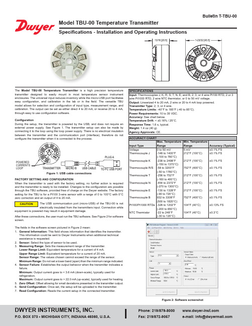
Model TBU-00 Temperature TransmitterSpecifications - Installation and Operating InstructionsBulletin T-TBU-00configure the transmitter when it is connected to the process.FACTORY SETTING AND CONFIGURATIONWhen the transmitter is used with the factory setting,no further action is requiredand the transmitter is ready to be installed. Changes to the configuration are possiblethrough the TBU software, provided free of charge on the Dwyer website. The factorysetting for the TBU is for a Pt100 3-wire sensor with a range of 0 to 100°C with 0°Czero correction and an output of 4 to 20 mA.After these connections, the user must run the TBU software. See Figure 2 for softwarescreen.The fields in the software screen pictured in Figure 2 mean:1. General Information: This field shows information that identifies the transmitter.This information could be sent to Dwyer Instruments when additional technicalassistance is requested.2. Sensor: Select the type of sensor to be used.3. Measuring Range: Sets the measurement range of the transmitter.Lower Range Limit: Equivalent temperature for a current of 4 mA.Upper Range Limit: Equivalent temperature for a current of 20 mA.Sensor Range: The values chosen cannot exceed the range of the sensor.Minimum Range: Do not set a lower band (span) than the minimum range indicated.4. Sensor Failure: Establishes the output behavior when the transmitter indicates afailure.Minimum: Output current goes to < 3.6 mA (down-scale), typically used forrefrigeration.Maximum: Output current goes to > 22.0 mA (up-scale), typically used for heating.5. Zero Offset: Offset allowing for small deviations presented in the transmitter output.6. Send Configuration: Once set, the setup will be uploaded to the transmitter.7. Read Configuration:Reads the current setup in the connected transmitter.SPECIFICATIONSFigure 1: USB cable connectionsFigure 2: Software screenshotPOWEREDLOOPThe USB communication port (micro-USB) of the TBU-00 is notelectrically insulated from the transmitters input. Connection whileequipment is powered may result in equipment damage.®MECHANICAL INSTALLATIONThe TBU-00 transmitter is suitable to be installed in instrument enclosures. Vibrations, moisture, extreme temperatures, electro-magnetic interference, high voltage, and other interferences can permanently damage the unit, and could cause an error in the measured value.ELECTRICAL INSTALLATIONRecommended wire size: 26 AWG to 16 AWG (0.14 to 1.5 mm 2).Recommended terminal torque: 7.08 in-lbf (0.8 Nm).RECOMMENDATIONS FOR INSTALLATIONSeparate signal lines from facility power lines. The use of grounded conduit is recommended.The instrument must be powered from the instrumentation power supply circuit.Transient suppression should be used with inductive loads such as contact coils and solenoids.ELECTRICAL CONNECTIONSThe figures below shows the electrical connections required. Terminals 3, 4, 5 and 6 are dedicated to the sensor connection. LOAD represents the 4 to 20 mA current measuring device (indicator, controller, recorder, etc.).Note: When using a Pt100Ω 2-wire RTD, terminals 3 and 4 must be interconnected, according to Figure 3 below. The Pt100 wire length should be less than 12 in (30 cm) to maintain the measurement error within specifications (electrical resistance).Figure 3: Pt100 2-wire Figure 5: Pt100 4-wireFigure 6: NTC 2-wireFigure 7: ThermocouplesFigure 4: Pt100 3-wirePt100 SENSORLOAD Pt100 SENSOR 3-WIREPt100 SENSORNTC SENSOR POWER SUPPLYFigure 8: Voltage (0 to 50 mV)OPERATIONThe sensor offset can be changed through the TBU-00 software. The USB cable may be connected to the transmitter without causing any measurement errors. See item 5 Zero Offset on the first page of this manual.The user must choose the most suitable sensor and range to the process. The selected range must not exceed the maximum range of measurement defined for the sensor and should not be smaller than the minimum range for the same sensor.Note: The transmitter accuracy is based on the maximum range of the sensor used, even when a narrower range is programmed.Example:• The Pt100 sensor in the range 0 to 100°C and accuracy of 0.12%, the maximum error will be 1.02°C (0.12% of 850 °C )• The Pt100 sensor in the range of 500 to 600°C and accuracy of 0.19%, the maximum error will be 1.61°C (0.19% of the 850°C )Note: When the measurements are made at the transmitter, ensure the Pt100 excitation current required by the calibrator is compatible with the Pt100 excitation current used in the transmitter: 0.8 mA.SAFETY INFORMATIONAny control system design should take into account that any part of the system has the potential to fail. This product is not a protection or safety device and its alarms are not intended to protect against product failures. Independent safety devices should always be provided if personnel or property are at risk.Product performance and specifications may be affected by its environment and installation. It’s the responsibility of the user to assure proper grounding, shielding, cable routing, and electrical noise filtering are in accordance with local regulations, EMC standards, and good installation practices.SUPPORTThis product contains no serviceable parts inside. For troubleshooting, visit our frequently asked questions at or contact our technical support team at 1-800-872-9141.MAINTENANCE/REPAIRUpon final installation of the Model TBU, no routine maintenance is required. The Model TBU is not field serviceable and is not possible to repair the unit. Field repair should not be attempted and may void warranty.WARRANTY/RETURNRefer to “Terms and Conditions of Sale” in our catalog and on our website. Contact customer service to receive a Return Goods Authorization number before shipping the product back for repair. Be sure to include a brief description of the problem plus any additional application notes.Printed in U.S.A. 5/19FR# 444508-00 Rev. 1©Copyright 2019 Dwyer Instruments, Inc.NOTES____________________________________________________________________________________________________________________________________________________________________________________________________________________________________________________________________________________________________________________________________________________________________________________________________________________________________________________________________________________________________________________________________________________________________________________________________________________________________________________________________________________________________________________________________________________________________________________________________________________________________________________________________________________________________________________________________________________________________________________________________________________________________________________________________________________________________________________________________________________________________________________________________________________________________________________________________________________________________________________________________________________________________________________________________________________________________________________________________________________________________________________________________________________________________________________________________________________________________________________________________________________________________________________________________________________________________________________________________________________________________________________________________________________________________________________________________________________________________________________________________________________________________________________________________________________________________________________________________________________________________________________________________________________________________________________________________________________________________________________________________________________________________________________________________________________________________________________________________________________________________________________________________________________________________________________________________________________________________________________________________________________________________________________________________________________________________________________________________________________________________________________________________________________________________________________________________________________________________________________________________________________________________________________________________________________________________________________________________________________________________________________________________________________________________________________________________________________________________________________________________________________________________________________________________________________________________________________________________________________________________________________________________________________________________________________________________________________________________________________________________________________________________________________________________。
USB-1SP8T-34 超宽带、实体状 SP8T 开关 USB说明书

THE BIG DEALy Super wide bandwidth, solid-state design y High isolation, 50 dB @ 30 GHz y USB control and automationy Daisy-chain control of up to 25 switchesPRODUCT OVERVIEWMini-Circuits’ USB-1SP8T-34 is a fast switching solid-state SP8T covering an ultra-wide bandwidth, from 0.1 to 30 GHz. The solid-state design features an impressive combination of high isolation, low insertion loss and good linearity across the entire band. The switch is supplied in a low profile package with precision 2.92 mm RF connectors.The daisy-chain control interface with “dynamic addressing” simplifies control integration, allowing multiple switches to be combined into a Master / Slave chain. Simply connect, then power on and the whole chain of up to 25 compatible switches can be controlled independently through a single USB and software interface.Full software support is provided, including our user-friendly GUI application for Windows and a full API with programminginstructions for Windows and Linux environments (both 32-bit and 64-bit systems).APPLICATIONSy RF signal routing / switch matricesy Satellite communications up to Ka band y Military radio, radar & electronic warfare y Microwave radio / cellular infrastructure y T est & measurement systemsTrademarks:Generic photo used for illustration purposes only SOFTWARE PACKAGERefer to our website for compliance methodologies and qualificationsELECTRICAL SPECIFICATIONS AT 0 TO 50°C1. Max power at hot switching derates linearly from +18 dBm @ 600 MHz to +17 dBm @100 MHz, at all other conditions it derates linearly from +24 dBm @ 600 MHz to +17 dBm @100 MHz.2. IP3 may degrade below 500 MHz to about +45 dBm.3. IP3 tested with 1 MHz span between signals, +8 dBm per tone.4. Transition time spec represents the time that the RF signal paths are interrupted during switching and thus is specified without communication delays.5. Minimum dwell time is the shortest time that can be achieved between 2 switch transitions when programming an automated switch sequence.6. Switching time (USB) is the time from issuing a single software command via USB to the switch state changing. The most significant factor is the host PC, influenced by CPU load and USB protocol. The time shown is an estimate for a medium CPU load and USB 2.0 connection.7. USB current draw for a single unit with no slave units.8. Pass through current is the maximum supply current handling of a unit with slave modules attached. If controlling a large number of slave modules additional power supplies should beABSOLUTE MAXIMUM RATINGSCONNECTIONSBLOCK DIAGRAM9. Mating connector is Hirose ST40X-10S-CV(30).Operating T emperature 0°C to 50°C Storage T emperature -20°C to 60°CDC supply voltage max.6V DC voltage @ RF Ports20 VPermanent damage may occur if any of these limits are exceeded. Operating in the range between operating power limits and absolute maximum ratings for extended periods of time may result in reduced life and reliability.Switch in DISCONNECT ED state50Ω50Ω50Ω50Ω50Ω50Ω50Ω50Ω50ΩControl & Power from Master (Serial In)Control & Power to slaves (Serial Out)USBOUTLINE DRAWING (NR3245)OUTLINE DIMENSIONS ( )AB C D E F G H J weight 5.30 2.000.5750.10 1.000.50 5.100.1060.65grams 134.6250.8014.610 2.5425.4012.70129.54 2.69016.51185INCHmmCONNECTING MULTIPLE MODULES (DAISY CHAIN)The USB-1SP8T-34 model is designed to connect up to 25 modules in series (daisy chain) using dynamic addressing, meaningthere is no need to specifically set the address of the modules. The addresses will be set automatically as part of establishing the communications with the computer. The module connected to the computer’s USB port will be assigned address 0 (master), the first module connected to it will get address 1 (slave) and subsequent modules incrementing up to address 24 (slave).Connections between modules will be made using the serial in/out ports with the module connected to the PC act as a master and all other as slave modules. All control will be through the master module (address 0) which is the only one communicating with the PC. Serial control out port of each module should be connected to the serial control in port of the next module.Power will be supplied from the PC via the master module up to a maximum of 500 mA. Generally, additional power supply will be needed to keep total current below 500 mA. All power supplies should be connected to the module via the module’s USB port. Connecting an additional power supply will automatically cut off power draw from the serial control in port for that module.The serial master/slave bus allows connecting modules of different types to the same daisy chain as long as all support Mini-Circuits Dynamic addressing setup. To add a new module to the setup, simply connect the module and refresh the address listing, no need to reset any of the existing modules or assign addresses manually.Note: Different module types may have different current consumption which will change the number of units which can be connected before an additional power supply is needed.SOFTWARE SPECIFICATIONSSOFTWARE & DOCUMENTATION DOWNLOAD:y Mini-Circuits’ full software and support package including user guide, Windows GUI, DLL files, programming manual and examples can be downloaded free of charge from: https:///softwaredownload/solidstate.htmlfor supporty Please contact ******************************USB SUPPORT (WINDOWS):y ActiveX COM DLL file for creation of 32-bit programs library DLL file for creation of 32 / 64-bit programsy Supported by most common programming environmentsUSB SUPPORT (LINUX):y Direct USB programming using a series of USB interrupt codesy Full programming instructions and examples available for a wide range of programming environments / languages.GRAPHICAL USER INTERFACE (GUI) FOR WINDOWS - KEY FEATURESy Connect via USBy Run GUI in “demo mode” to evaluate software without a hardware connectiony View and set switch states at the click of a buttony Control up to 25 units from a single USB controly Configure and run timed switching sequencesy Set start-up switch stateORDERING INFORMATIONPlease contact Mini-Circuits’ T est Solutions department for price and availability: ******************************OPTIONAL ACCESSORIESUSB-CBL-AC-3+ 3.3 ft (1.0 m) USB Cable: USB type A (Male) to USB type C (Male)CBL-1.5FT-MMD+ 1.5 ft (0.45 m) cable assembly for serial control Daisy Chain with snap fit connectorsUSB-AC/DC-5AC/DC +5V power adaptor with USB connector 10, 1110. The power adaptor may be used to provide additional power via USB port when connecting several units in daisy chain.11. Includes power plugs for US, UK, EU, IL, AU & China. Plugs for other countries are also available. If you need a power cord for a country not listedplease contact ******************************NOTES:。
FW353使用手册
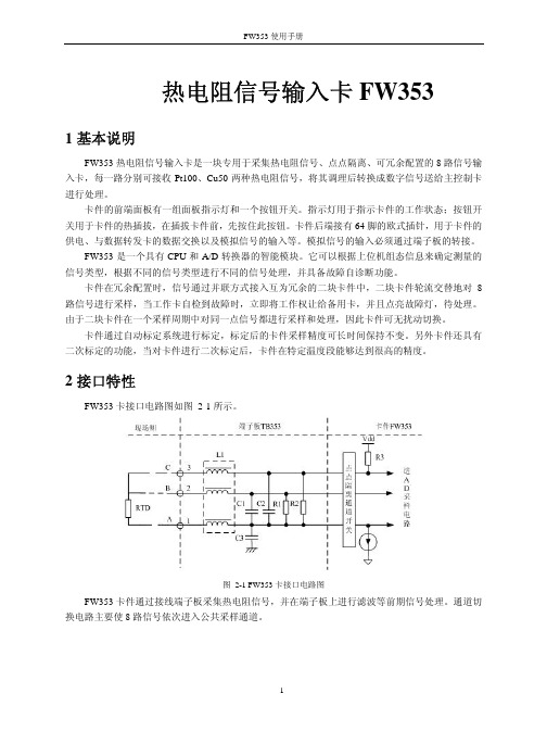
其它
工作温度
≥0℃,≤+50℃
工作湿度
≥5%,≤90%(不结露)
存储温度
≥-40℃,≤+70℃
存储湿度
≤95%(不结露)
工作大气压
≥62 kPa,≤108kPa
5 工程应用说明举例
FW353 热电阻输入卡支持两种信号类型:Pt100 和 Cu50 ,采用三线制测量方法。在工程应用 中,FW353 组态比较简单。首先根据信号选择类型组态,FW 353 有三种信号类型,Pt100、Cu50、 Pt100 小量程。Pt100 小量程应用在量程范围比较小,精度要求比较高的场所。
4 性能指标
表 4-1 FW353 性能指标
型号
FW353
电源
供电
5V 电源 24V 电源
(5±0.3)VDC,Imax<100mA (24±0.7)VDC,Imax<10mA
技术指标
通道数
8路
通道隔离方式
点点隔离
隔离电压
现场侧与系统侧 通道间
500VAC 50Hz 60s 60VAC 50Hz 60s
3.5 端子板选择
FW353 热电阻信号输入卡在使用时必须与对应的端子板配合使用。选配标准如下:
表 3-3 FW353 的端子板选配
描述 8 路热电阻 RTD 输入端子板 16 路热电阻 RTD 输入端子板
型号 TB353-R
TB353
使用范围 电阻信号 电阻信号
备注 可配置两冗余 FW353 卡 可配置两不冗余 FW353 卡
卡件通过自动标定系统进行标定,标定后的卡件采样精度可长时间保持不变。另外卡件还具有 二次标定的功能,当对卡件进行二次标定后,卡件在特定温度段能够达到很高的精度。
AX-353 数字多功能AC噪音多尺寸测量仪说明书
AX-353DIGITALER AC-ZANGENMULTIMETER3 ¾ ZIFFER MIT AUTOMATISCHER MESSBEREICHUMSCHALTUNG BEDIENUNGSANLEITUNGDieses Messgerät ist ein tragbarer, digitaler AC-Zangenmultimeter mit einer 3 ¾-stelligen LCD-Anzeige, automatischer Bereichsumschaltung und automatischer Abschaltung. Dank seiner Eigenschaften ist es ideal für die Arbeit im Gelände, im Labor, in Geschäften und für zu Hause.1. SPEZIFIKATIONEN1.1. ALLGEMEINE SPEZIFIKATIONENDisplay: LCD 3 ?Ziffer mit maximalem Messwert 3999. Bereichumschaltung: automatisch oder manuell.Polarität: Automatische Anzeige der negativen Polarität. Nullstellung: Automatisch.Anzeige für Messbereichüberschreitung: Am Display erscheint nur …OL“ oder …-OL“.Anzeige der leeren Batterien: Symbol …“ am Display. Automatische Abschaltung: Nach 30 Minuten Inaktivität schaltet das Messgerät automatisch ab. Das Einschalten des Messgerätes ist durch Drücken einer beliebigen Taste oder Drehen des Schalters möglich.Sicherheitsstandards: Das Gerät erfüllt die Anforderungen der Norm IEC1010 für Doppelisolierung, Verschmutzungsgrad 2, Überspannungskategorie III.Öffnungsspalt der Zange: 38mm. Betriebsbedingungen: Temperatur 0~40°C (32~104°F), Relative Luftfeuchtigkeit ≤ 80%.Lagerbedingungen: Temperatur 20~60°C (-4~140°F), Relative Luftfeuchtigkeit ≤ 90%.Spannungsversorgung: 3 x 3V-BatterieAbmessungen: 189mm (Höhe)× 55mm (Breite)× 24mm (Tiefe).Gewicht: ca. 150g (mit Batterien).1.2. ELEKTRISCHE DATENDie Genauigkeit ist bestimmt als ± (% des Messwerts + dem Wert der letzten Stelle) bei 23±5°C und relativer Luftfeuchtigkeit ≤ 75%.DC Spannung400mV, 4V, 40V, 400V: ±(0.5%+2)600V : ±(0.8%+2)Impedanz: 10MΩ, über 100MΩ im 400mV-Messbereich.AC Spannung400mV bei 50 bis 500Hz: ±(3.0%+5)4V bei 50 bis 500Hz: ±(1.0%+3)600V bei 50 bis 100Hz: ±(3.0%+5)Impedanz: 10MΩ, über 100MΩ im 400mV-Messbereich.AC Strom400A bei 50 bis 60Hz: ±(2.0%+5)500A bei 50 bis 60Hz: ±(2.5%+5)Überlastschutz: 600Arms 60 Sekunden lang.Widerstand400Ω:±(1.2%+8)4KΩ, 40KΩ, 400KΩ, 4MΩ:±(1.0%+2)40MΩ:±(2.0%+3)Überlastschutz: 250V DC/250Vrms ACKapazität40nF: ±(3.0%+10)400nF, 4µF, 40µF:±(2.5%+5)100µF (15s):±(5.0%+10)Überlastschutz: 250V DC/250Vrms ACFrequenz4Hz,40Hz,400Hz,4KHz,40KHz,400KHz,4MHz,10MHz:±(0.5%+4)Empfindlichkeit: 0.6Vrms(10MHz: 1.5Vrms)Füllfaktor: 0.1%~99.9%Überlastschutz: 250V DC/250Vrms ACTemperatur≤150°C: ±(3°C+1)>150°C: ±(3%+1)Bereich: -20°C~+800°CSonde: NiCr-NiSiÜberlastschutz: 250V DC/250Vrms ACDiodenprüfungTeststrom: 1,0±0,7mATestspannung: Etwa 1,5VÜberlastschutz: 250V DC/250Vrms ACDurchgangstestSignalton: beim Widerstand unter ca. 50Ω.Testspannung: Etwa 0,5VÜberlastschutz: 250V DC/250Vrms AC2. WARNUNGEN1) Vor einer Spannungsmessung stellen Sie sicher, dass dasMessgerät sich nicht im Messbereich für Strom, Widerstand,Diode, Kontinuität, Kapazität oder Temperatur befindet.2) Seien Sie äußerst vorsichtig bei der Messung vonSpannung über 50V, vor allem in Schaltungen mit hoherEnergie.3) Soweit möglich, sollten Sie den das Messgerät nicht an dieSchaltung unter Spannung anschließen.4) Vor der Widerstandsmessung, Dioden- und oderKontinuitätstest, Kapazitäts- oder Temperaturmessungstellen Sie sicher, dass die Schaltung vollständig entladenwurde.5) Stellen Sie sicher, immer die richtige Messfunktion und denrichtigen Messbereich gewählt zu haben.6) Behalten Sie besondere Vorsicht bei Messungen vonStromtransformatoren mit abgeschaltetem Last.7) Vor der Durchführung der Messung, stellen Sie sicher,dass die Leitungen in gutem Zustand sind und die Isolationnicht beschädigt ist.8) Die in der Spezifikation des Messgerätes angegebenGrenzwerte dürfen nicht überschritten werden.9) Vor dem Öffnen des Batteriefachs zum Austausch derBatterien trennen Sie die Messleitungen von allen externenStromkreisen und schalten Sie das Messgerät aus, indem Sieden Drehschalter auf …OFF” stellen.10) Bei Messungen mit der Messsonden halten Sie IhreFinger hinter den Schutzabdeckungen.2.1. Prüfen des BatteriezustandsWenn die Batterien leer sind, erscheint auf der rechten Seitedes Displays das Symbol …“. In diesem Fall sollen Sie dieBatterien gegen neue austauschen.2.2. Funktionstasten1) …F“-TasteMit dem Drücken dieser Taste im Messbereich …Ω” kanndie Widerstandsme ssung, Diodenprüfung, Test derKontinuität oder Kapazitätsmessung gewählt werden.2) …Range“-TasteDurch Drücken dieser Taste wird auf Handumschaltmodusgewechselt. Beim nächsten Drücken erfolgt eineUmschaltung des Messbereiches. Wenn Sie die Taste fürmehr als 2 Sekunden gedrückt halten, wird zurück aufautomatische Umschaltung des Messbereiches gewechselt.Die manuelle Umschaltung des Messbereiches ist nichtverfügbar für die Messfunktionen Frequenz/Tastgrad und Kapazität.3) Taste …Hz/%“Das Drücken dieser Taste im Bereich der Frequenzmessung wird auf die Tastverhältnismessung umschalten.Beim erneuten Drücken kehrt das Gerät zur Frequenzmessung zurück.Im Messbereich von Spannung ermöglicht das Drücken dieser Taste die Messung der Frequenz / des Tastverhält nisses, aber der Bereich wird niedriger und es wird die manuelle Messbereichumschaltung aktiviert.4) Taste …H/☼“Durch Drücken dieser Taste in jedem beliebigen Messbereich wird der aktuelle Wert der Anzeige angehalten und das Symbol …DH“ angezeigt.Beim ern euten Drücken wird die Anzeigefunktion ausgeschaltet und das Symbol …DH“ erlischt. Durch Drücken und Halten der Taste für mehr als 2 Sekunden wird die Hintergrundbeleuchtung des Displays eingeschaltet, beim erneuten Drücken und Halten der Taste länger als 2 Sekunden wird die Hintergrundbeleuchtung ausgeschaltet. 2.3. Messung der DC- und AC-Spannung1) Schließen Sie die schwarze Messleitung an die …COM“-Buchse und die rote Messleitung an die …VΩHz“-Buchse an.2) Stellen Sie den Messbereich-Drehschalter auf …DCmV, DCV“oder …AVC“.3) Schließen Sie die Messsonden an die gemessene Quelle oder Last.2.4. Strommessung AC1) Stellen Sie den Messbereich-Drehschalter auf …ACA”.2) Öffnen Sie die Zange durch Drücken der Taste und legen Sie die Leitung (nur eine) ein, deren Strom Sie messen möchten.3) Schließen Sie die Zange und lesen Sie das Messergebnis auf dem LCD-Display ab.Hinweis:a) Vor Beginn der Messung trennen Sie die Messleitungen vom Messgerät.b) Bei Schwierigkeiten, das Messergebnis am Display abzulesen, drücken Sie die Taste …H/☼“, damit das Messergebnis später abgelesen werden könnte.2.5. Widerstandsmessung1) Schließen Sie die schwarze Messleitung an die …COM“-Buchse und die rote Messleitung an die …VΩHz“-Buchse an. 2) Stellen Sie den Drehschalter auf…Ω“; es sollte dieWiderstandsmessfunktion ausgewählt sein; wenn es nicht derFall ist, drücken Sie …F“, um auf die Widerstandsmessfunktionumzuschalten.3) Schließen Sie die Messsonden an den gemessenenSchaltkreis an.Hinweis: Stellen Sie sicher, dass die Schaltung nicht unterSpannung steht und vollständig entladen ist.Maximaler Überlast des Eingangs:250V rms über < 10Sekunden.2.6. Kapazitätsmessungen1) Schließen Sie die schwarze Messleitung an die…COM“-Buchse und die rote Messleitung an die…VΩHz“-Buchse an.2) Stellen Sieden Drehschalter auf …Ω“ und drücken Siedie Taste …F”, um die Funktion der Kapazitätsmessung zuwählen.3) Schließen Sie die Messsonden an den gemessenenSchaltkreis an.Hinweis:a) Vor Beginn der Messung sollen die Kondensatorenvollständig entladen werden.b) Bei der Kapazitätsmessung führt der Multimeter dieLadung des Kondensators durch. Somit braucht man im Fallder größeren Kapazitäten mehr Zeit, um das endgültigeErgebnis der Messung (im 100μF-Messbereich beträgt dieseZeit ca. 15 Sekunden) zu erhalten.c) Bei der Messung kleineren Kapazitäten(40μF-Messbereich) sollte die tatsächliche Kapazitätswert alsdie nach der Messung angezeigte Wert abzüglich der vor derMessung angezeigten Wert berechnet werden.d) Maximaler Überlast des Eingangs:250V rms über <10Sekunden.2.7. Frequenzmessung1) Schließen Sie die schwarze Messleitung an die…COM“-Buchse und die rote Messleitung an die…VΩHz“-Buchse an.2) Stellen Sie den Drehschalter in die …Hz”-Stellung.3) Schließen Sie die Messsonden an die gemessenen Punktean und lesen Sie das Ergebnis der Frequenzmessung an derAnzeige ab.4) Drücken Sie …Hz/%“, um die Tastverhältnis-Messungdurchzuführen.Drücken Sie die Taste erneut, um zurFrequenzmessung zurückzukehren.Hinweis:Maximaler Überlast des Eingangs:250V rms über < 10Sekunden.2.8. Diodentest und Durchgangsprüfung1) Schließen Sie die schwarze Messleitung an die…COM“-Buchse und die rote Messleitung an die…VΩHz“-Buchse an.2)Stellen Sie den Drehschalter in die …Ω“-Stellung.3) Drüc ken Sie die Taste …F“, um den Diodentest oder dieDurchgangsprüf ung zu wählen.a) Um den Diodentest durchzuführen, schließen Sie dieschwarze Messsonde an die Kathode der Diode (-) und dierote Messsonde an die Anode der Diode (+) an und lesen Sieam Display den Wert des Spannungsabfalls in derVorwärtsrichtung ab.Bei einem verpolten Anschluss vonMesssonden wird am Display die Überschreitung desMessbereiches angezeigt.b) Um den Kontinuitästest durchzuführen, schließe n Sie dieMesssonden an den gemessenen Kreis an. Wenn derWiderstand zwischen den Sonden kleiner als 50Ω ist, ertöntein Piepton.Hinweis:Stellen Sie sicher, dass die Schaltung nicht unterSpannung steht und vollständig entladen ist.Maximaler Überlast des Eingangs:250V rms über < 10Sekunden.2.9. Temperaturmessung1) Schließen Sie die schwarze Messleitung an die…COM“-Buchse und die rote Messleitung an die…VΩHz“-Buchse an.2) Stellen Sie den Drehschalter in die Stellung … C“.3) Stellen Sie die Temperatursonde am Messort.Hinweis:Maximaler Überlast des Eingangs:250V rms über < 10Sekunden.2.10. Automatischer/manueller Wechsel derMessbereicheAutomatischer Messbereichwechselmodus ist eine nützlicheFunktion, aber es passiert, dass der manuelle Auswahl eineschnellere Messung ermöglicht, wenn der gemessene Wertungefähr bekannt ist.Um den manuellen Bereichwechselmodus zu wählen,drücken Sie die Taste …Range“, bis Sie den gewünschtenMessbereich auswählen.Beim jeden Drücken der…Range“-Taste erfolgt die Umschaltung auf einen höherenMessbereich. Wenn Sie die Taste …Range“ mehr als 2Sek unden lang gedrückt halten, wird zurück auf dieautomatische Umschaltung des Messbereiches gewechselt.Im Frequenz-/Tastverhältnis- und Kapazitätsmessmodus istdie manuelle Umschaltung des Messbereiches nicht möglich. Hinweis:Wenn im manuellen Bereichwechselmodus am Display die Anzeige …OL“ erscheint und das Messgerät einen intermittierenden Ton erzeugen wird, schalten Sie sofort auf einen höheren Bereich um.3. PFLEGE UND WARTUNG3.1. Die folgenden Tipps sollen Ihnen helfen, Ihr Messgerät jahrelang in gutem Zustand zu halten.1) Halte Sie den Multimeter trocken. Wenn das Gerät nass wird, sollten Sie es sofort trocken wischen. Flüssigkeiten können Mineralien enthalten, die Korrosion der elektronischen Schaltkreisen verursachen.2) Benuzen und lagern Sie das Gerät in der normalen Temperaturumgebungen. Sehr hohe oder sehr niedrige Temperaturen können die Lebensdauer der elektronischen Komponenten des Gerätes verkürzen, Batterien beschädigen sowie Kunststoffteile verformen oder schmelzen.3) Behandeln Sie das Messgerät sorgfältig.Das Herunterfallen des Messgerätes kann Schäden an Komponenten oder Gehäuse verursachen sowie zu den Fehlfunktionen des Multimeters führen.4) Halten Sie den Multimeter fern von Staub und Schmutz. Beides kann zum erhöhten Verschleiß dessen Bauteilen führen.5) Wischen Sie das Gehäuse-Multimeter ab und zu mit einem feuchten Tuch, um es sauber zu halten. Reinigen Sie nicht den Multimeter mit aggressiven Chemikalien oder starken Reinigungsmitteln.6) Es sollen immer neue Batterien eines geeigneten Typs verwendet werden. Entfernen Sie leere Batterien aus dem Messgerät, da sie auslaufen können, was zu den Schäden an den elektronischen Schaltkreisen des Messgerätes führt.3.2. Batteriewechsel1) Stellen Sie sicher, dass das Multimeter an keinen externen Stromkreis angeschlossen ist. Stellen Sie den Drehschalter auf …OFF” und trennen Sie die Messleitungen von den Buchsen des Messgerätes.2) Öffnen sie den Deckel am Batteriefach mit einem Schraubendreher.3) Wechseln Sie alte Batterien auf die neuen des gleichen Typs.4) Schließen Sie den Batteriedeckel und ziehen Sie die Schraube fest.。
- 1、下载文档前请自行甄别文档内容的完整性,平台不提供额外的编辑、内容补充、找答案等附加服务。
- 2、"仅部分预览"的文档,不可在线预览部分如存在完整性等问题,可反馈申请退款(可完整预览的文档不适用该条件!)。
- 3、如文档侵犯您的权益,请联系客服反馈,我们会尽快为您处理(人工客服工作时间:9:00-18:30)。
接线端子板TB353-U
1基本说明
TB353-U端子板为16路端子板,可供2块不冗余FW353(B)卡使用,实现16路热电阻信号的输入处理。
每路热电阻信号为三线制接线方式。
2使用说明
2.1端子板外观图
TB353-U端子板结构外形如图 2-1所示。
端子板尺寸:218mm×75mm 。
图 2-1 TB353-U端子板结构外形图
2.2接插件说明
表 2-1 TB353-U端子板接插件说明
标号 说 明
J1 第一块卡(1号卡)数据连线插座
J2 第二块卡(2号卡)数据连线插座
J3 1号卡接线端子
J4 2号卡接线端子
2.3 接口特性
图 2-2接口特性图
2.4 端子定义及接线
TB353-U 接线说明如表 2-2所示。
每路热电阻信号为三线制接线方式,热电阻的三个接点分别描述为A 、B 、C 。
例如把一个热电阻信号接到FW353(B )卡的第一通道上,那么TB353-U 端子板接线端子1连接A 、端子2连接B 、端子3连接C 。
表 2-2 接线说明
卡号
接线图
信号端子接线 通道1(CH1)
1 2 3 A B C
通道2(CH2)
4 5 6 A B C
通道3(CH3)
7 8 9 A B C
通道4(CH4)
10 11 12 A B C
通道5(CH5)
13 14 15 A B C
通道6(CH6)
16 17 18 A B C
通道7(CH7)
19 20 21 A B C
通道8(CH8)
22 23 24 一 号 卡
A B C
通道9(CH9)
25 26 27
A B C
通道10(CH10)
28 29 30
A B C
通道11(CH11)
31 32 33
A B C
通道12(CH12)
34 35 36
A B C
通道13(CH13)
37 38 39
A B C
通道14(CH14)
40 41 42
A B C
通道15(CH15)
43 44 45
A B C
通道16(CH16)
46 47 48
二
号
卡
A B C 3资料版本说明
表 3-1版本升级更改一览表
资料版本号更改说明
TB353-U使用手册(V1.0)适用模块版本:TB353-U-V11.00.00
3。
