日立空调机组GW协议转换器使用说明书
日立空调技术手册
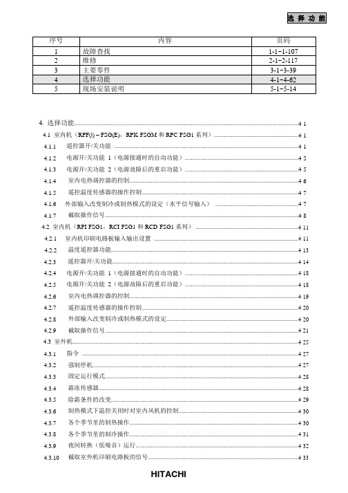
4. 选择功能..................................................................................................................................................4-1 4.1 室内机(RPF(l) – FSG(E),RPK-FSGM 和 RPC-FSG1 系列).......................................................4-1 4.1.1遥控器开/关功能........................................................................................................................4-1 4.1.2电源开/关功能1(电源接通时的自动功能)..........................................................................4-5 4.1.3电源开/关功能2(电源故障后的重启功能)..........................................................................4-5 4.1.4室内电热调控器的控制..............................................................................................................4-6 4.1.5遥控温度传感器的操作控制......................................................................................................4-7 4.1.6外部输入改变制冷或制热模式的设定(水平信号输入)......................................................4-7 4.1.7截取操作信号..............................................................................................................................4-8 4.2 室内机(RPI-FSG1,RCI-FSG1 和 RCD-FSG1 系列) ...................................................................4-11 4.2.1室内机印刷电路板输入输出设置..............................................................................................4-11 4.2.2温度遥控器功能..........................................................................................................................4-13 4.2.3遥控器开/关功能.........................................................................................................................4-14 4.2.4电源开/关功能1(电源接通时的自动功能)..........................................................................4-18 4.2.5电源开/关功能2(电源故障后的重启功能)..........................................................................4-18 4.2.6室内电热调控器的控制..............................................................................................................4-19 4.2.7遥控温度传感器的操作控制......................................................................................................4-20 4.2.8外部输入改变制冷或制热模式的设定......................................................................................4-20 4.2.9截取操作信号..............................................................................................................................4-21 4.3 室外机...................................................................................................................................................4-25 4.3.1指令.............................................................................................................................................4-27 4.3.2强制停机......................................................................................................................................4-27 4.3.3固定运行模式..............................................................................................................................4-28 4.3.4霜冻传感器..................................................................................................................................4-28 4.3.5除霜条件的改变..........................................................................................................................4-29 4.3.6制热模式下温控关闭时对室内风机的控制..............................................................................4-30 4.3.7各个季节里的制热操作..............................................................................................................4-30 4.3.8各个季节里的制冷操作..............................................................................................................4-31 4.3.9夜间转换(低噪音)运行..........................................................................................................4-32 4.3.10截取室外机印刷电路板的信号..................................................................................................4-334.4遥控器PC-2H2.....................................................................................................................................4-35 4.4.1零件名称......................................................................................................................................4-35 4.4.2同步运行......................................................................................................................................4-36 4.4.3双遥控器操作系统......................................................................................................................4-38 4.4.4功能设定选择..............................................................................................................................4-39 4.4.5遥控器功能选择..........................................................................................................................4-42 4.4.6 寻址(ADDS)和制冷剂循环编号(RN)显示 .....................................................................4-474.5无线遥控器PC-LH3 ............................................................................................................................4-48 4.5.1零件名称......................................................................................................................................4-48 4.5.2室内机组并列安装的识别..........................................................................................................4-49 4.5.3同步运行......................................................................................................................................4-50 4.5.4紧急操作......................................................................................................................................4-52 4.5.5选择功能设定..............................................................................................................................4-53 4.5.6无线遥控器的选择功能..............................................................................................................4-54 4.6七日时控器,PSC-3T..........................................................................................................................4-55 4.7中央控制器PSC-3S1 ...........................................................................................................................4-57 4.7.1零件名称......................................................................................................................................4-57 4.7.2系统.............................................................................................................................................4-58 4.7.3中央控制器的操作步骤..............................................................................................................4-60选择功能(4.1室内机) 4.选择功能4.1室内机(RPI(I) – FSG(E),RPK-FSGM和RPC-FSG1系列)4.1.1遥控器开/关功能该功能提供远程自动停机或系统启动的控制。
上海日立家用电器有限公司空调使用说明书
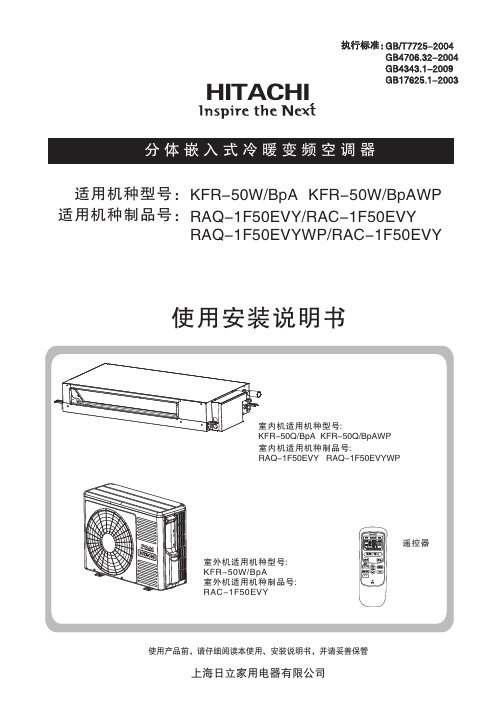
使用产品前,请仔细阅读本使用、安装说明书,并请妥善保管使用安装说明书KFR-50W/BpA KFR-50W/BpAWP 适用机种型号:适用机种制品号:HITACHIRAQ-1F50EVY/RAQ-1F50EVYWP/RAC-1F50EVYRAC-1F50EVY执行标准:GB/T7725-2004GB4706.32-2004GB4343.1-2009GB17625.1-2003使用说明目 录注意事项......................................................................................................................................1产品主要技术参数........................................................................................................................3.....................................................................................................................................................9.....................................................................................................................................................10.....................................................................................................................................................11一键清洁功能.............................................................................................................................................11.....................................................................................................................................................12遥控器电池的更换法.................................................................................................................................12.............................................................................................................................13.....................................................................................................................................14故障查找......................................................................................................................................2机组介绍.....................................................................................................................................................4接收器指示说明.........................................................................................................................................4室内机部品名称.........................................................................................................................................5运转之前.....................................................................................................................................................5遥控器各部分名称和功能.........................................................................................................................6自动运转.....................................................................................................................................................8制热运转除湿运转制冷运转送风运转睡眠定时器的设定功能定时器的设定功能自动控制.. (15)安全须知......................................................................................................................................16安装所需的工具及仪器.............................................................................................................................16运输及吊装.................................................................................................................................................17室内机的安装.............................................................................................................................................17排水管的安装.....................................................................................................................................21接收器(显示接受操作系统)的安装.......................................................................................23保护和控制装置室外机的安装 制冷剂管道安装真空排气顺序电线连接试运行...............................................................................................................................................................23............................................................................................................................................24室外机冷凝水处理.....................................................................................................................................25.........................................................................................................................................25.............................................................................................................................................28.....................................................................................................................................................29.........................................................................................................................................................31附图 (32)安装说明图例意义如下注意事项•电源为单相 220V~ 电压如电压低于或高出正常电压10%以上,空调器将不能正常工作甚至烧断保险丝,易损坏空调器,建议配用220V~ 稳压器。
日立室内 室外分体空调说明书

I L G N EINDOOR UNIT/OUTDOOR UNITSPLIT TYPE AIR CONDITIONERTI N U R O O D N I T I N U R O O D T U O S H Instruction manualRAS-DX10HNK /RAC-DX10HNK RAS-DX13HNK /RAC-DX13HNK RAS-DX18HNK /RAC-DX18HNKRAS-DX10HNK RAS-DX13HNKRAC-DX10HNK RAC-DX13HNK RAC-DX18HNKRAS-DX18HNKSleep Right/Left SilentF .Wash To obtain the best performance and ensure years of trouble free usage, please read this instruction manual completely.請詳細閱讀這本使用說明書以了解正確使用方法,及使機器可長期地發揮最高性能。
PRECAUTIONS DURING SHIFTING OR MAINTENANCEW A R N I N G Should abnormal situation arises (like burning smell), please stop operatingthe unit and turn off the circuit breaker. Contact your agent. Fault, shortcircuit or fire may occur if you continue operating the unit under abnormalsituation.Please contact your agent for maintenance. Improper self maintenance may cause electric shock and fire.Please contact your agent if you need to remove and reinstall the unit.Electric shock or fire may occur if you remove and reinstall the unit by yourself improperly.PRECAUTIONS DURING OPERATIONW A R N I N GFor the sake of health, avoid facing to direct airflow for a long period of time.Do not use any conductor as fuse wire, this could cause fatal accident.During thunderstorm, disconnect and turn off the circuit breaker.If the supply cord is damaged, it must be replaced by the manufacturer,qualified persons in order to avoid a hazardits service agent or SAFETY PRECAUTIONPlease read the “Safety Precaution” carefully before operating the unit to ensure correct usage of the unit.Pay special attention to signs of“ Warning” and “ Caution”. The “Warning” section contains matters which,if not observed strictly, may cause death or serious injury. The “Caution” section contains matters which may resultin serious consequences if not observed properly. Please follow all instructions strictly to ensure safety.The signs indicate the following meanings.Make sure to connect earth line. The sign in the figure indicates prohibition.Indicates the instructions that must be followed.Please keep this manual after reading.PRECAUTIONS DURING INSTALLATIONWARNING Do not reconstruct the unit.Water leakage, fault, short circuit or fire may occur if you reconstruct the unitby yourself.Please ask your sales agent or qualified technician for the installation of your unit. Water leakage, short circuit or fire may occur if you install the unit by yourself.Please use earth line.Do not place the earth line near water or gas pipes, lightning-conductor, orthe earth line of telephone. Improper installation of earth line may causeelectric shock.CAUTIONA circuit breaker should be installed depending on the mounting site of theunit. Without a circuit breaker, the danger of electric shock occurs.Do not install in the location nearby or with flammable gas. The outdoor unit may catch fire if flammable gas leaks around it.Please ensure smooth water flow when installing the drain hose.Do not put your fingers or rods into the air outlet or suction port.If the fans of indoor and outdoor units are running at high speed, which may cause injury or malfunction.PRECAUTIONS DURING OPERATIONW A R N I N GThe product shall be operated under the manufacturer specification and notfor any other intended use.•Do not attempt to operate the unit with wet hands, this could cause fatal accident.•When operating the unit with burning equipments, regularly ventilatethe room to avoid insufficiency of oxygen.•Do not direct the cool air coming out from the air-conditioner panel to facehousehold heating apparatus as this may affect the working of apparatus such asthe electric kettle, oven etc.•Please ensure that outdoor mounting frame is always stable, firm andwithout defect. If not, the outdoor unit may collapse and cause danger.•Do not splash or pour water to the body of the unit when cleaning as this maycause short circuit.•Do not use any aerosol or hair sprays nearby the indoor unit. The chemicalcan adhere on heat exchanger fin and block the evaporation water flowing todrain pan. The water will drop on tangential fan and cause water splashing outfrom indoor unit.•Please switch off the unit and turn off the circuit breaker during cleaning, the high-speed fan inside the unit may cause danger.•Turn off the circuit breaker if the unit is not to be operated for a long period.•Do not climb on the outdoor unit or put objects on it.•Do not put water container (like vase) on the indoor unit to avoid waterdripping into the unit. Dripping water will damage the insulator inside the unitand cause short circuit.•Do not place plants directly under the air flow as it is bad for the plants.•••This appliance is not intended for use by young children or infirm persons unless they have beenYoung children should be supervised to ensure that they do not play with the appliance.adequately supervised by a responsible person to ensure that they can use this appliance safely.••This appliance is not to be used by children or persons with reduced physical, sensory ormental capabilities, or lack of experience and knowledge, unless they have been givensupervision or instruction. Children must be supervised not to play with the appliance.•When operating the unit with the door and windows opened, (the room humidity is always above80%) and with the air deflector facing down or moving automatically for a long period of time,waterwill condense on the air deflector and drip down occasionally. This will wet your furniture.Therefore,do not operate under such condition for a long time.If the amount of heat in the room is above the cooling or heating capability of the unit (for example:more people entering the room, using heating equipments and etc.), the preset room temperaturecannot be achieved.ENGLISHNAMES AND FUNCTIONS OF EACH PARTINDOOR UNIT OUTDOOR UNITAIR FILTERTo prevent dust from coming into the indoor unit. (Refer page 23)Sleep Right/Left Silent F .Wash RAS-DX10HNK RAS-DX13HNK RAS-DX18HNK780792280420215299RAC-DX10HNK/RAC-DX13HNK/RAC-DX18HNK RAS-DX10HNK/RAS-DX13HNK 1050290220RAS-DX18HNK CAUTIONTurn off the circuit breaker or pull outthe power plug if the unit is not beoperated for a long period.INDOOR UNIT INDICATORSLight indicators showing the operating condition.(Refer page 5)FRONT PANEL(Refer page 5)HORIZONTAL DEFLECTOR • VERTICALDEFLECTOR (AIR OUTLET)(Refer page 18)REMOTE CONTROLSend out operation signal to the indoor unit so as tooperate the whole unit.(Refer page 7)Condensed water will drain to outside.C ONNECTION CORDATTACHING AND REMOVING FRONT PANELRECEIVABLE INDICATOR FUNCTIONSOPERATION INDICATORTEMPORARY SWITCHWhen the remote control device is not functioning, use the t emporary s witch mode .(1)When the Temporary Switch is pressed, the unit will operate as per the previous setting. After the power source is turne d off and turn on again, the operation is done in automatic mode.(2)Press the Temporary Switch again will stop the operation of the air conditioner.TEMPORARY SWITCHOPERATION LAMP (Yellow)This lamp lights during operation.FROST WASH LAMP (Green)TEMPORARY SWITCHTIMER LAMP (Orange)This lamp lights when the timer is working.RAS-DX10HNKRAS-DX13HNK RAS-DX18HNKEN G L I S H While gripping both the left and right edges [recessed in the front ] of the front panel, lift up to open the front panel.After completion, slightly lift up the front panel and pull down to close the front panel. Ensure that the 3 sets of left, centre and right clips are fully secured.••AUTO RESTART FUNCTIONPerforms heating operation when the room temperature is below 23°C.Set the temperature to be around 23°C.Performs dehumidifying operation when the room temperature is 23~27°C.The preset temperature will be the room temperature at the start time of air conditioner operation.Performs cooling operation when the room temperature is above 27°C.Set the temperature to be around 27°C.The auto restart feature prompts the air-conditioner to restart in its previous setting right after the power failure. In case of the power failure during the use of timer mode (Sleep Timer or ON/OFF Timer), timer mode is cancelled and the air conditioner stops.Please reset the remote control to restart the unit after the power has been restored.AUTOMATIC OPERATIONHeating Dehumidifying Cooling Air Filter Claw Filter FrameC-caseAir purifying filterAttaching the air purifying filters (Accessories) to the filter frame.•Attach the air purifying filters to the designated position.•The cooling capacity is slightly weakened and the cooling speed becomes slower when the air purifying filters are used.•The air purifying filters are not washable. It is recommended to use vacuum cleaner to clean. It can be used for 1 year. When you want to replace it, please ask your sales agent.HOW TO REPLACE THE BATTERIES IN THE REMOTE CONTROL12Remove the cover as shown in the fi gure and take outthe old batteries.Push and pull to thedirection of arrowInstall the new batteries.The direction of the batteries should match the marksin the case.1.Do not mix the new and old batteries, or use differentkinds of batteries together.2.Take out the batteries when you do not use the remotecontrol for 2 or 3 months.CAUTIONAir purifying filterF-coverRAS-DX10HNKRAS-DX13HNK RAS-DX18HNKEN G L I S H NAMES AND FUNCTIONS OF REMOTE CONTROLThis controls the operation function and timer setting of the room air conditioner. The applicable range of control is about 7 meters. lf indoor lighting is controlled electronically, the range of control may be shorter.Precautions for Use•Do not put the remote control under direct sunlight or high temperature.•Do not drop it on the fl o or, and prevent from water.•If you press the MODE selector button during operation, the compressor may stop for about 3 minutes for protection before you can start it again.Signal Transmission(DEHUMIDIFY) (COOL) and cyclically.( Page 8)ECO Button Use this button to set theECO mode.( Page 17)TIMER OFF Button Select the Timer OFF.( Page 12)TIMER ON Button Select the Timer ON .( Page 12)SLEEP TIMER Button Use this button to set the sleep timer. ( Page 19)POWERFUL Button Press this button to start powerful operation.( Page 13)Transmission Sign The transmission sign blinks when a signal has been sent .ON/OFF ButtonPress this button to startoperation.Press it again to stop operation. TEMPERATURE ButtonRoom temperature setting.Value will change quicker whenkeep pressing.FAN SPEED ButtonSelect the fan speed for coolingmode.UP/DOWN (Horizontal) Button Control the angle of the horizontal air deflector. ( Page 18)RIGHT/LEFT (Vertical) ButtonControls the angle of the vertical air deflector.( Page 18)SILENT ButtonUse this button to set the SILENT mode.( Page 20)FROST WASH Button( Page 14)Sleep Right/Left Silent F .Wash MODE selector Button Use this button to select the operating mode. Every time you press this button, themode will change from (AUTO)(HEAT)(FAN)AUTOMATIC OPERATIONThe device will automatically determine the mode of operation, HEAT or COOL depending on the current room temperature. The selected mode of operation will change when the room temperature varies.-8 -HEATING OPERATIONDefrosting will be performed about once an hour when frost forms on the heat exchange of the outdoor unit , it takes about 5-10 minutes of each cycle.During defrosting operation, the operation lamp blinks in cycle of 2 seconds on and 1 second off. The maximum time for defrosting is 20 minutes.(If the piping length used is longer than usual, frost will likely to form.)●Use the unit for heating when the outdoor temperature is under 27°C.When it is too warm (over 27°C), the heating function may not work in order to protect the unit .●In order to keep reliability of the unit , please use this device above –2°C of the outdoor temperature.-9 -EN G L I S HDEHUMIDIFYING OPERATION■Dehumidifying FunctionUse the unit for dehumidifying when the room temperature is over 16°C.When it is under 15°C, the dehumidifying function will not work.● When the room temperature is higher than the temperature setting: The unit will dehumidify the room,reducing the room temperature to the preset level.When the room temperature is lower than the temperature setting: Dehumidifying will be performed at the temperature setting slightly lower than the current room temperature, regardless of the temperature setting.●The preset room temperature may not be reached depending on the number of people present in the roomor other room conditions.Set the desired room temperature with the ROOMTEMPERATURE setting button (the display indicates the setting).The range of 20°C to 26°C is recommended asthe room temperature for dehumidifying.Temperature range can be set between 16°C and32°C.Press the (ON/OFF) button. Dehumidifying operationstarts with a beep. Press the button again to stop operation.■As the settings are stored in the memory of the remote control, youonly have to press the (ON/OFF) button next time.START STOP Press the MODE selector button so that the displayindicates (DEHUMIDIFY).The fan speed is set at LOW.Press (FAN SPEED) button to select SILENT or LOW fanspeed.12Sleep Right/LeftSilent F .Wash Sleep Right/LeftSilentF .WashEN G L I S H COOLING OPERATIONPress the MODE selector button so that the display indicates(COOL).■As the settings are stored in memory in the remote control, you only have to press the (ON/OFF) button next time.123Set the desired FAN SPEED with the (FAN SPEED) button (thedisplay indicates the setting).START STOP ■During AUTO fan, the fan speed automatically changes as below:●When the difference between room temperature and setting tem-perature is large, fan starts to run at HI speed.●After room temperature reaches the preset temperature, fan speedwill be changed to lower speed to obtain optimum room temperaturecondition for natural healthy airflow .(AUTO) (HIGH) (MED)(SILENT) (LOW)Set the desired room temperature with the TEMPERATURE button(the display indicates the setting).The temperature setting and the actual room temperature may varyd epending on conditions.Temperature range can be set between 16°C and 32°C.Press the (ON/OFF) button. Cooling operation starts with abeep. Press the button again to stop operation. The cooling functiondoes not start if the temperature setting is higher than the currentroom temperature (even though the (OPERATION) lamp lights).The cooling function will start as soon as you set the temperaturebelow the current room temperature.Use the unit for cooling when the outdoor temperature is 7 to 43°C.If indoor humidity is very high (over 80%), some dew may form on the air outlet grille of the indoor unit.Sleep Right/LeftSilent F .Wash Sleep Right/Left Silent F .WashFAN OPERATIONUser can use the unit simply as an air circulator.START STOP 12Press the MODE selector button so that the display indicates(FAN).Press the (ON/OFF) button. Fan operation starts with a beep.Press the button again to stop operation.Press the (FAN SPEED) button.(HIGH) (MED) (LOW) (SILENT)Timer ReservationOFF TIME setting•Select the OFF TIME by pressing the Button.•Setting time will change according to the below sequence when you press the button.1 hour intervalTIMER RESERVATIONON Timer and OFF Timer are available.21 ON TIME setting •Select the ON TIME by pressing the Button.•Setting time will change according to the below sequence when you press the button.Timer off1 hour intervalTimer on Operation stop at setting time .Operation will start for settingtemperature at setting time.Sleep Right/LeftSilentF .Wash Right/LeftF .Wash Right/LeftF .WashSTART●The dust and dirt adhering to indoor heat exchanger is the cause of the smell. They are washed away by freezing and thawing of the heat exchanger.●●Indoor Frost Wash function can work when the outdoor temperature is 1℃ to 43℃ and indoor humidity is 30%to 70%. There are two kinds of Indoor Frost Wash operation, auto mode and manual mode.INDOOR FROST WASH OPERATION※ It depends on the conditions of the room.The process of Indoor Frost WashAbout 8 min About 20 min to 90 min.Operation such as cooling operation Freezing and thawing heat exchanger Auto StopRunning Stop The deflectors remain opened duringfan operation, freezing, thawing.●If you want to stop Indoor Frost Wash operation, press the (ON/OFF ) button twice.● lamp on the indoor unit lights up during Indoor Frost Wash operation.Indoor Frost Wash starts Indoor Frost Wash ends●When pressing the button such as cooling during Indoor Frost Wash operation, Indoor Frost Wash operation is discontinued and start the cooling operation after about 3 minutes.●When Indoor Frost Wash is stopped during Indoor Frost Wash operation, the unit automatically restart Indoor Frost Wash operation when the next operation stops.●In order to protect the unit , Indoor Frost Wash function cannot be carried out again for about 60 minutes after Indoor Frost Wash operation is completed." "Fan operation ■ Indoor Frost Wash (Auto mode)Indoor Frost Wash auto start conditions●When the outdoor temperature or indoor humidity are not suitable for Indoor Frost Wash operation, only fan operation is carried out, Indoor Frost Wash operation will be done again after the next operation stops.●Sometimes the heat exchanger may not freeze depending on the conditions of the room.●When the ON timer reaches the set time during Indoor Frost Wash operation, it will stop the Indoor Frost Wash operation and start the operation of setting mode.●If the interval of the Off to On timer is less than 2 hours, Indoor Frost Wash operation may not be completed. In that case, it will restart Indoor Frost Wash operation after the next operation stops.Once the auto mode of Indoor Frost Wash operation interval (42 hours) is reached, stop operating the air conditioner and activate Indoor Frost Wash in Auto or Manual mode.Accumulated operating hours of the air conditioner have exceeded 42 hoursAir conditioner is stopped operating for more than 30 minutes, such as coolingoperation Indoor Frost Wash startIndoor Frost Wash end About 20 min to 90 min.About 30 minutes or more Operation such as cooling operation Operation such ascooling operation Last Indoor Frost Wash Running Stop Running StopAuto StopIndoor Frost Wash Accumulated operating hours of the air conditionerhave exceeded 42 hoursFROST WASH OPERATION-15 -EN G L I SH Precautions for Use● Hissing, fizzy or squeaking noise may generate during Indoor Frost Wash operation.●After turning on the power, please wait a moment if you want to start Indoor Frost Wash.Upon completion of Indoor Frost Wash with manual mode, operation interval (42 hours) of Indoor Frost Wash with auto mode will be re-calculated.● ●Do not open windows or doors during Indoor Frost Wash operation. Water will condense on the air deflector and drips down occasionally. This will wet your furniture.●Do not open or remove the front panel during Indoor Frost Wash operation. It may cause injury or malfunction.●Indoor Frost Wash operation does not wash away all dust and dirt.●If the air conditioner is continuously running, Indoor Frost Wash function is not effective.●During Indoor Frost Wash operation, if power is turned off and then power is restored, Indoor Frost Wash function will not restart.-16 -STARTCANCELIn case the power consumption is already low,AUTO SWING OPERATIONVERTICAL SWING■To start Vertical Auto Swing■To cancel Horizontal Auto Swing●Press (UP/Down (HORIZONTAL)) button. The deflectors willis displayed on the LCD.●Press (Right/L eft (VERTICAL )) button. The defl ectors willstart to swing right and left.is displayed on the LCD.●Press (UP/Down (HORIZONTAL )) button again. The deflectorswill stop at the current position.disappeared from the LCD.●Press (Right/Left (VERTICAL)) button again. The defl ectorswill stop in the current position.disappeared from the LCD.NOTEstart to swing up and down.Sleep Right/LeftF .Wash Silent Sleep Right/Left F .Wash SilentHORIZONTAL SWING■To start Horizontal Auto Swing■To cancel Vertical Auto Swing●●During cooling and dehumidifying operation, do not keep the de fl ectors swinging or in the lower position (in the case of vertical auto swing) for a long time. It may cause dew condensation on the de fl ectors.To avoid accidents, do not adjust deflectors with your hands.EN G L I S H SLEEP TIMER OPERATIONThe timer can be set up to a duration of 7 hours.By pressing (SLEEP) button during AUTO, DEHUMIDIFYING, COOLING or FAN operation, the unit shifts the room temperature and reduces the fan speed. It results in energy saving.■To start SLEEP TIMER operationPress (SLEEP) button during operation.● “”, “”, “ ” and number of hours are displayedon the remote control display.●During SLEEP TIMER operation, fan speed will be ultra●slow.● A beep sound emitted from indoor unit and the TIMER lampon the indoor unit lights up.Pressing (SLEEP) button repeatedly, the number of hourswill change as below:●During SL EEP TIMER operation, air conditioner willcontinue operating for the designated number of hours andthen turn off.■To cancel SLEEP TIMER operation■Press (On/Off) button.●Air conditioner will switch off.Press (SLEEP) button again until “”, “”,“ ” and number of hours disappear from the remotecontrol display.1 1 H2 H3 H 7 HSLEEP TIMER offSleep Sleep Sleep SleepSleep Sleep Right/Left F .Wash SilentSILENT OPERATION●By pressing (SIL ENT) button during DEHUMIDIFYING, COOL ING or FAN operation, the fan speed will change to ultra slow.■To start SILENT operation■To cancel SILENT operation●Press (SILENT) button during operation.“ ” is displayed on the LCD. Fan speed will be ultra slow.●Press (On/Off) button.●Press (SIL ENT) button again or (FAN SPEED)button.Fan speed will return to previous fan speed before SIL ENToperation starts.SILENT operation stops , “ ” disappears from the LCD.1SilentSilentSilentSleep Right/Left F .Wash Silent NOTE●●When POWERFUL operation is selected, SILENT operation is cancelled. Fan speed wil l return to previous fan speed before SILENT operation.After auto restart, SILENT operation is cancelled. Fan speed will return to previous fan speed before SILENT operation." (SLIENT), fan speed will not change even if p ressing ●If the operation is running with fan speed " " " (SLIENT) button.THE IDEAL WAYS OF OPERATIONSuitable Room TemperatureWarningFreezing temperatureis bad for health and awaste of electric power.Install curtain or blindsI t i s p o s s i bl eto reduce heatentering the roomthrough windows.VentilationCautionDo not close the room for a long period of time. Occasionally open the door and windows to allow theentrance offresh air.Effective Usage Of Timer At night, please use the " sleep timer " mode, together with your wake up time in the morning. This will enable you to enjoy a comfortable room temperature. Please use the timer effectively.Do Not Forget T o Clean The Air Filter Dusty air filter will reduce the air volume and the cooling efficiency. To prevent from wasting electric energy, please clean the filter every 2 weeks.TemperaturenPlease Adjust Suitable TemperatureFor Baby And ChildrenPlease pay attention to the room temperatureand air flow direction when operating the unitfor baby, children and old folks who havedifficulty in movement.(The ideal temperaturedifference betweenoutdoor and indooris about f5°C).ENGLISHFOR USER’S INFORMATIONThe Air Conditioner And The Heat Source In The Room CautionIf the amount of heat in the room is above thecooling capability of the air conditioner (for example:more people entering the room, using heatingequipments and etc.), the preset room temperaturecannot be achieved.Not Operating For A Long TimeWhen the indoor unit is not to be used for a longperiod of time, please pull out the power plug. Or theindoor unit still consumes about 1W in the operationcontrol circuit even if it is in “OFF” mode.OFFWhen Lightning OccursWarningTo protect the whole unit during lightning, pleasestop operating the unit and remove the plug from thesocket.Interference From Electrical ProductsCautionTo prevent interference, place at least 1m away.TV Inverter-type fluorescent lamp.To avoid signal interference, please place the indoor unit and its remote control at least 1m away from electrical products.MAINTENANCE OF THE UNITS CAUTIONEnsure that the unit is not in operation and all power supply has been disconnected before cleaning the unit.Dust Filter ScreenDust filter screens are installed to remove the indoor dust particles hence they should be kept clean at all times. They should be cleaned at each machine operation cycle of approximately 100 hours. Excessive dust collected at the dust filter screen will block the air flow, reduce the cooling capability and could produce noise. Therefore the dust filter screen should be cleaned as per instructions given below:Cleaning Instructions(1)Removing the dust filter screen•While holding both edges of the front panel, open up and lift the front panel and push in to park at the secured position.Front panelFront cabinet•Slightly lift up the dust filter screen, release the latch clips [2 places] located at the bottom of the front cabinet and move the dust filter screen downward to remove it from the unit.(2)U se a vacuum cleaner to vacuum clean the dust accumulated at the dust filter screen. If the accumulated dustis too much to be removed by vacuum cleaning, apply mild detergent and flush the dust from the dust filter screen with water. After thorough rinsing, leave the dust filter screen at a cool shaded place to dry.(3)R e-install the dust filter screen to its original position (With “FRONT” marker facing front). Slightly lift up theopened front panel and close it by returning it to its original position.(4)E ach year before using the air conditioner, clean the heat exchanger (evaporator) with a fine soft brush or avacuum cleaner and take care to avoid damaging the evaporator fins.Front panelDust filter screenLatch clipCAUTION•Do not use hot water (40e C or above) to rinse the dust filter screen, otherwise the screen will warp and get distorted. After rinsing, shake the dust filter screen to rid off all remaining water droplets and place it at a cool shaded place to dry. Avoid placing the dust filter screen under direct sunlight, otherwise the screen will warp and get distorted.Do not operate the air conditioner unit without the dust filter screen, otherwise the ingress of dust into the air conditioner unit will cause breakdowns.E N G L I S H。
日立风冷热泵空调说明书
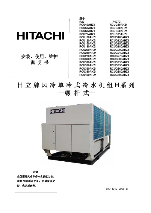
安装、使用、维护说 明 书日立牌风冷单冷式冷水机组H 系列--螺 杆 式--Z0011312- 2008- B型号R22 R407CRCU40AHZ1 RCUG40AHZ1 RCU50AHZ1 RCUG50AHZ1 RCU60AHZ1 RCUG60AHZ1 RCU75AHZ1 RCUG75AHZ1 RCU100AHZ1 RCUG100AHZ1 RCU120AHZ1 RCUG120AHZ1 RCU150AHZ1 RCUG150AHZ1 RCU180AHZ1 RCUG180AHZ1 RCU200AHZ1 RCUG200AHZ1 RCU240AHZ1 RCUG240AHZ1 RCU270AHZ1 RCUG270AHZ1 RCU300AHZ1 RCUG300AHZ1 RCU330AHZ1 RCUG330AHZ1 RCU350AHZ1 RCUG350AHZ1 RCU360AHZ1 RCUG360AHZ1 RCU380AHZ1 RCUG380AHZ1 RCU400AHZ1 RCUG400AHZ1重要通知●日立对产品的设计和性能将不断进行改良,规格如有更改,恕不另行通知。
●日立对每一个可能的情况可引致有潜在的危险不作预测。
●没有书面允许,此说明书不得翻印。
●信号字句(危险,警告和小心)用于鉴别危险性的级别,有关各信号字句所提示的危险性解释 如下:: 可能导致严重个人受伤或死亡的直接危险。
: 危险或不安全的操作可能导致严重个人受伤或死亡。
: 危险或不安全的操作可能导致轻微个人受伤或产品或财物损害。
: 对使用或维修有帮助的资料。
●如有需要,请联络您所聘用之承建商或日立分销商。
●此说明书提供其他型号的风冷单冷式冷水机组的共同描述和资料。
●此风冷单冷式冷水机组是根据以下温度设计,冷水机组应在此范围使用:工作范围● 此说明书为风冷单冷式冷水机组的永久部件,应保留在冷水机组内。
● 下表为本说明书中所叙机组的能效等级汇总:机型能效 等级 机型能效等级机型 能效 等级机型 能效 等级RCU40AHZ1 4 RCU200AHZ1 3 RCUG40AHZ1 5 RCUG200AHZ14 RCU50AHZ1 3 RCU240AHZ1 3 RCUG50AHZ15 RCUG240AHZ1 4 RCU60AHZ1 3 RCU270AHZ1 3 RCUG60AHZ1 4 RCUG270AHZ1 4 RCU75AHZ1 3 RCU300AHZ1 3 RCUG75AHZ1 4 RCUG300AHZ1 4 RCU100AHZ1 3 RCU330AHZ1 3 RCUG100AHZ1 5 RCUG330AHZ1 4 RCU120AHZ1 3 RCU350AHZ1 3 RCUG120AHZ1 4 RCUG350AHZ1 4 RCU150AHZ1 3 RCU360AHZ1 3 RCUG150AHZ1 4 RCUG360AHZ1 4 RCU160AHZ1 3 RCU380AHZ1 3 RCUG160AHZ1 5 RCUG380AHZ1 4 RCU180AHZ1 3RCU400AHZ1 3 RCUG180AHZ1 4 RCUG400AHZ14*依据国家标准:GB19577-2004 作为能效等级判定。
日立-水冷式柜式空调-安装,使用,维护说明书

制冷能力不足 1.检查机组的冷却水供应是否充足? 2.检查温控器之设定是否正确。 3.检查空气滤网是否堵塞。
保养工作 1.请清洗或更换空气滤网。 2.请使用中性清洁剂清洁机体外盖板。 3.请清洗露水盘及管路。 4.请清洗冷却水管路(此工作建议找有专业经
136 144 155 145 730 670 360
390
RP-16WSL
132 141 189 142 730 670
360
390
RP-20WSL
171 191 189 189 830 870
350
400
RP-25WSL1 220 186 225 189 860 840 495
405
RP-30WSL1 266 245 291 225 1030 970 495
拉引。 4. 逆相保护继电器-在于主电源为 415V(额定电压)时,请按照图示,将(A)连接线去除后,再将(B)套子(标
准附件)套在两端子上。(请参照下图) 5. 当安装冷却水塔时,需按照图 7 指示之端子之间提供连锁回路。
机体
电气箱
1 2 R S T Mp (L 1 (L 2 (L 3 (N) )))
吸入风管时的状态。若须安装吸入风管时,“D”尺寸须变为 1500mm。
3. 尺寸 C 是指 RP-25WSL1、RP-30WSL1、RP-40WSL 的滤网,
安装到机体的服务空间。若空气滤网服务空间改为左侧时,
“B”尺寸须变为 1000mm。
图 2 最大倾斜角度
型号
RP-16WS RP-16WSL RP-20WSL
主电源 电源开关
CMT
图 7 现地配线 备注: 1. 只有在三相四线的电源下才配线到 MP 端子。 2. CMT:冷却水塔用电磁接触器之辅助触点。
Hitachi 分体式壁挂式变频热泵消费者指南说明书

Split System: Wall Mounted Inverter Heat PumpsConsumer Guide<($5:$55$17<,1&5($6,1* <285&20)2576Imagine choosing your perfect day theninstantly creating it in the comfort of your own home. With Hitachi heat pumps you create your favourite season anytime, at the touch of a button.The choice is yours. Welcome to Another Hitachi Day.Comfort All Year RoundThere’s nothing worse than having a cold house all winter long–waking up in the morning to freezing temperatures, cold surroundings and damp air.In summer, it can be hard to cool a stuffy house that‘s been shut up all day, or to be comfortable on humid evenings, when open windows can pose a security risk and invite insect problems.Now, with an Hitachi wall mounted heat pump, you can control your everyday environment day and night, all year round.Our heat pumps provide effective cooling at temperatures as high as 43°C outside, and out-perform other heating systems at temperatures as low as –10°C.Energy StarThis logo is awarded to appliances that are among the most energy effi cient on the market in their class at the time of testing. Only Energy Star models can qualify for a heat pump subsidy under EECA’s ‘Warm Up NZ’ campaign.(Refer back page Specifi cations table).Save power, save moneyHitachi advanced technology leads in power effi ciency. A measure of this effi ciency is called the Coeffi cient Of Performance, or COP . Hitachi heat pumps have excellent COP . For every 1 kW of electricity used by our heat pumps, more than 3.5 kW of heating or 3 kW of cooling is delivered to your room. The Energy Effi ciency graph below shows how effective our heat pumps are compared to other heating methods.Heat Pump air conditioningElectric fan heater Natural Gas heaterLPG heater Oil heaterCoal slow combustionCoal open fire0 50 100 150 200 250 300 350 400Efficiency %Installing an Hitachi heat pump means no more heat going up the chimney, andno more cluttering up your home with a host of power hungry appliances.What is more, our heat pumps disperse warm or cool air throughout your room, unlike traditional radiators.Another Hitachi DayEnhance the value ofyour homeHitachi modern air conditioning systems are compact, elegant, and unobtrusive. Each system comprises an indoor unit (wall mounted) and an outdoor unit (located near the house), sized to suit the area to be air conditioned. Select from a range of models all designed to blend in with your environment.Indoor:R AS-50YHA3 RAS-60YHA3Outdoor: R AC-50YHA3 RAC-60YHA3Total Hitachi ComfortTotally Safe…Even when you are not at home.Outdoor DurabilityWith its special anti-corrosion “green” coating, the Green Fin Condenser lasts up to three times as long as standard types. This coating on theoutdoor heat exchanger assures better performance and improves durability even in tough conditions such as those incoastal areas. * Models RAS-25YHA3 and RAS-35YHA4 have a transparent anti-corrosiontreatment applied.Low Starting Current and Auto RestartHitachi DC Inverter technology uses a low starting current, to minimise power usage at start up. For convenience, Hitachi heat pumps are able to memorise the precise operation mode, air fl ow, temperature and timing settings. If there is a power cut, settings will automatically reset to the original operating mode once power is restored.LCD Remote System ControllersThe handy infrared remote control allows you toaccurately select the desired room temperature from the comfort of your armchair. All commands are shown clearly on the liquid crystal display. A smart system of one touch buttons can create the perfect environment with ease.The new SPX-WKT1 Weekly Timer is available as an optional extra. Offering 5 different programs for each calendar day with start and end times and temperature control. Customise settings for “Weekly Program” or use the “Temporary Operation Mode”. Choice of 5 fan settings: Auto/High/Medium/Low/Sleep.Green anti-corrosioncoating*SaltcontentAir Water Corrosion resistant layer ■ Base material ■SPX-WKT1 Weekly Timer –featuring remote functionsRAS-50YHA3 RAS-60YHA3RAS-70YHA3 RAS-80YHA3RAS-25YHA3 RAS-35YHA4Pre-FilterAir Purifying FilterA Breath of Fresh AirAfter 24 hoursBefore deactivationNano Titanium Air Purifying FilterShuts out germs, bacteria and allergens.Nano Titanium particles are minute particles that catch and neutralize bacteria, mould and odour molecules which are approximately 1,000 times larger.The Air Purifying Filter uses both these incredibly small nano titanium particles and anti-bacterial Silver Agents to trap and eliminate microbes as well as neutralise allergens and remove harmful substances such as formaldehyde.Nano Titanium Pre-Filter*The pre-fi lter which covers the entire air inlet to stop dust and other particles from entering is also coated with nano titanium.The two-stage action of nano titanium in both the pre-fi lter and the purifying fi lter ensures that bacteria and odours are removed from the air.*Optional Nano Titanium on RAS-25/35.Deactivation EffectSample: Escherichia coli.Bacteria (sample Escherichia coli) is deactivated by 99% in 24 hours. (Tested by SIRIM QAS International Sdn, Bhd. Report No: 2004KLO100).Silver ActionSilver Agents.Silver agents are also included in the air purifying fi lter to effi ciently catch and deactivate ing the action of the nano titanium catalyst which is 1/200 the size of regular antibacterial and silver agents, microbes are captured and effectively neutralised to provide a powerful deodorising effect.distributors ofModel: Indoor Unit RAS-25YHA3RAS-35YHA4RAS-50YHA3RAS-60YHA3RAS-70YHA3RAS-80YHA3Capacity *Cooling Capacity (kW) 2.5 3.5 5.0 6.07.08.0Range ( kW )0.9 ~ 3.11.1 ~ 4.20.9 ~ 5.80.9 ~ 6.81.5 ~ 8.31.5 ~ 8.5Heating Capacity (kW) 3.4 4.5 6.17.08.39.0Range (kW)0.9 ~ 4.41.1 ~ 5.60.9 ~ 6.80.9 ~ 7.51.5 ~ 9.71.5 ~ 9.7Dehumidifying Capacity (l/h)1.4 1.62.8 2.8 4.8 4.8Effi ciencyPower Input kW (Cooling)0.670.94 1.48 1.80 2.05 2.45Power Input kW (Heating)0.85 1.10 1.66 1.99 2.36 2.75EER / AEER (Cooling) 3.73 / 3.74 3.72 / 3.74 3.38 / 3.34 3.33 / 3.22 3.41 / 3.28 3.27 / 3.35COP / ACOP (Heating) 4.00 / 3.87 4.09 / 3.85 3.67 / 3.80 3.52 / 3.62 3.52 / 3.66 3.27 / 3.26Star Rating Cool / Heat ////// ENERGY STAR®YesYesYesYesYesYesDimensions & weightsDimensions IU (H x W x D mm) 280 / 780 / 220280 / 780 / 220295 / 1030 / 207295 / 1030 / 207333 / 1150 / 245333 / 1150 / 245Weight IU (kg)9.59.511111616Dimensions OU (H x W x D mm) 548 / 750 / 288548 / 750 / 288650 / 850 / 298750 / 850 / 298800 / 850 / 298800 / 850 / 298Weight OU (kg)333645505252Noise levelsSound Pressure Level IU dB(A) ✝ (Hi / Med / Low / Sleep) 38 / 32 / 26 / 2243 / 35 / 29 / 2647 / 39 / 28 / 2449 / 41 / 32 / 2947 / 42 / 33 / 3049 / 45 / 40 / 36Sound Pressure Level OU (dB) Cool / Heat46 / 4946 / 4950 / 5250 / 5151 / 5355 / 55InstallationPipe Connection Sizes: Gas (mm) (in)9.5 (3/8)9.5 (3/8)12.7 (1/2)12.7 (1/2)15.9 (5/8)15.9 (5/8)Pipe Connection Sizes: Liquid (mm) (in) 6.35 (1/4) 6.35 (1/4) 6.35 (1/4) 6.35 (1/4) 6.35 (1/4) 6.35 (1/4)Max. Pipe Length (m) (min./max.) 3 / 20 3 / 20 3 / 30 3 / 30 3 / 30 3 / 30Max. Height Difference (m)101010202020Pipe Connection MethodFlare Flare Flare Flare Flare Flare FeaturesNano Titanium Air Purifying Filter Yes Yes Yes Yes Yes Yes Nano Titanium Pre-Filter Optional Optional Yes Yes Yes Yes Anti Corrosion Fin (O/U Coil)TransparentTransparentGreen Green Green Green Indoor Fan – Anti-Bacterial Coating Yes Yes Yes Yes Yes Yes Multi-Directional Air Flow ––––Yes Yes Weekly Timer SPX-WKT1OptionalOptionalOptionalOptionalOptionalOptionalRange of operation: Cooling -10˚C to 43˚C, Heating -15˚C to 21˚C. * AS/NZ3823.2 ✝ Japanese Industry Standard. Refrigerant: R410A.Note: Materials and specifi cations subject to change without prior notice due to the manufacturer’s ongoing research and development programme.Wall Mounted Single Split System Specifi cationsYour local Hitachi dealer:3760a 09/12Peace of MindTemperzone Ltd distributes Hitachi heat pumps throughout New Zealand.Hitachi heat pumps from temperzone have a 6 year warranty on parts and labour.It’s a comfort to know that this warranty is backed by Temperzone Ltd, the largest air conditioning manufacturer and exporter in Australasia: founded, owned and operated by New Zealanders since 1956.Easy InstallationYour temperature problems can be solved in a matter of hours.Call us today for your no obligation on site inspection and quote.Six year warranty Energy Effi cient Quiet and DiscreetConvenient comfort control‘Hitachi ticks all the boxes’<($5:$55$17<,1&5($6,1* <285&20)2576。
日立空调机组GW协议转换器使用说明书

日立空调机组GW协议转换器使用说明书————————————————————————————————作者:————————————————————————————————日期:——目录——1.LONWORKS技术概况2.G/W协议转换器3.机组测的设定和接线4.试运行5.LONWORKS变量SNVT定义6.报警代码转换表1.LONWORKS技术概况美国Echelon公司1991年推出的LON技术,又称LONWORKS技术是计算机控制技术第三代的现场总线技术。
LONWORKS技术是一个实现控制网络系统的完整平台。
这些网络包括智能设备或节点.括智能设备或节点与它们所处的环境进行交互作用,以及通过不同的通信介质与其它节点进行通信。
这种通信采用一种通用的、基于消息的控制协议—LONTALK协议。
由于LONTALK协议已固化在神经元芯片(微处理器)内,节点通过网络变量的形式交换信息,又有现成的网络管理工具进行网络管理。
所以建立一个LONWORKS控制网络在网络通讯上几乎不需要任何调试工作量。
LONWORKS技术的网络通信对用户是透明的,神经元芯片自动完成LONWORK S的所有七层的网络协议,用户所要作的只有两件事:第一件事是指定哪些信息是通过网络变量传递的,也就是定议网络变量;第二件事是指定信息传递传递的发起者和接收者,也就是做Binding(网络变量的捆绑)。
2.G/W协议转换器(其型号为HARC70-C)G/W协议转换器是日立公司提供的通信用网关设备(可简称G/W).是把广州日立冷机有限公司内部用的H-link通信协议转换成公开的LONTALK协议的设备。
是便于用户通过通信网络监控日立的冷水机组为目的开发的一种通信协议转换器.1)系统构成方式以下是用G/W协议转换器联接到BMS(楼宇控制系统)系统时的系统构成简图.对于构成系统的其它部品请参阅相应的使用说明书.注意事项:1)冷水机组测的通信线上一定要加上附带的线圈和电容.2)屏蔽线要采用D类接地标准备注:上位装置可使用LONWORKS /RS232C型的G/W(ECHELON制SLTA—10 通用的LONTALK 收发器等)及相应的软件。
GWV系列并网逆变器用户手册说明书
Dongguan Sheng Yang Industrial Co., Ltd.SY-GWV300/500W Grid Tie InverterUser ManualThis data is a copyright of DongguanShengYang Industrial Co.Ltd.Without the written permission of the copyright holder, any unit or individual shall not be duplicate, disclosed to others orused,or we will be held liable in liability. This guide and the latest information maybe have someerror, but we will improve on time. If no prior notice changes, but incorporated into the new usermanual, Dongguan Sheng Yang Industrial Co., Ltd. has the final say.Tel:+86-0769-********/85372132/85372133Fax:+86-0769-********/85099281Website:Address:NO.1Shang Xin Road, Xin Rong Cun, Xin’an Community,Chang’an Town,Dong Guan City,Guang Dong ProvinceProduct picturesSystem Function●Power line carrier-current communication(Follow-up perfect)By using electric power as a carrier of AC alternating current, can modulate high-frequency software-processa ble (60KHz) in AC wire transmission and can achieve the communication/ newsletter between inverters or between inverter and computer. And it can transfer the power data and the brightness date of the sunshine in the real-time. Also monitor all functions of inverter.1、Carrier frequency:60KHZ(Frequency customizable)2、Interface way:TTL level serial interface3、Carrier rate:300BPS4、Serial rate:9600BPS(Can customize according to customer's request)5、Modulation mode:FSK+DSSS6、Newsletter distance:2Km●Display function1、AC voltage display2、Outage display3、Power shows4、AC frequency display5、DC over-voltage display6、DC under- voltage display7、Power adjust display●12-grade power searchIn overcast weather,the solar battery’s output current is extremely tiny, then inverter will automatic open 12-grade power search function.1、The program can automatically open power adjustment for 12 times.2、The current direction can adjust from the maximum to the minimum.3、In automatic adjustment process, we will see the LOW light flashing.And the power will keep as a starting point,from 0 to the maximum output power, and it will restart at most for 12 times, then locked in the maximum power, the ST lamp long bright.4、It need 10 minutes for 12-grade power search.●Wide voltage input(15-60VDC)Achieve wide voltage input.1、DC voltage input:15-60VDC2、Second level power variable voltage conversion●High-frequency two-way and one-way grid function1、High frequency direct modulation, AC half wave synthesis2、Two-way grid means: Load consume directly. And can reverse AC current transmission.3、One-way grid means: Load consume directly. And banned reverse AC current transmission.●Kinds of frequency output function.It can apply to 50Hz and 60Hz frequency of AC.Frequency range: 45Hz ~ 63Hz●directly connected to the solar panels (do not need to connect the battery)Using precise Dynamic differential pressure type MPPT function, APL functions, the inverter automatically adjust the solar panels of maximum output power,simply connect the solar panel to the grid inverters. Do not need to connect the battery.1、Differential pressure type MPPT: 0.1 V accuracy2、Power lock: 10W (AC output)●AC 0 angle with high precision auto-detectionAC phase angle of 0 through isolation amplifier then input to the MCU for high-precision detection and analysis.The phase shift rate is less than 1%, thus achieve high-precision with phase modulation AC output together.1、AC phase shift: < 1%2、Over-zero protection: 0.2 V AC3、AC switching: 50Hz / 60HzSynchronous High-frequency ModulationIn the process of the grid, usually adapt the same phase angle in parallel. (ie, When the two-phase alternating current total is equal to e switch to combination the two AC fusion) and the product is rectified AC half-frequency AC to 100Hz first, then the machine use the high frequency current in the circuit and semi-100Hz frequency alternating current generated combination, to achieve high-frequency modulation.1、Modulation synthesis: half wave and full-bridge modulation synthesis (100Hz / 120Hz)2、Synthetic way: MOSFET full-bridge3、High frequency: 50KHzPure Sine Wave OutputUse SPWM directly to make pure sine wave output.1、Output waveform: Adopt complementary PWM to push-pull pure sine wave.2、Generate means: enhancement-mode SPWM●Automatic Sensing Function Solar LuminosityUse the latest luminosity perception operation technology. The different illuminate angle and intensity of the solar panel will produce different current output. Use advanced CPU to operate the different illuminance and the data can be directly displayed on the LCD. Then you can visually see the sense of the strength of the sun unit.Used more convenient.1、Luminosity sampling point :power sampling point2、High precision AD sampling: integral AD sampling methodPower Automatically Locked (APL)In different current fluctuations, we should use the MPPT function. When the MPPT function adjusted to the maximum power point, the product automatically powers locked in maximum power point, then made the output power more stable.1、Power lock: The biggest sampling point of MPPT.Automatically Adapt To Different Load Power FactorAdapt to any of the power load.●Constant Current, Constant PowerThis product is constant current, constant output power, without any overload, over-current phenomenon.●Automatically Shut Down When The Power Output Of a FaultWhen the city power system is in failure, the inverter will automatically turn off the output.Current Limit ProtectionCurrent limit●Stack Multiple Machines●Multiple small power inverters in parallel can achieve large output power.●High-Frequency High Conversion RateAdapt high frequency converter, the output more efficient.Maximum Power Point Tracking (MPPT)Because the current intensity and the voltage changes at any time, if there is no power point tracking, there will be a lot of problems. In the past time, usually adopt a solar controller, but this product uses high-precision MPPT operation power, automatic and immediate adjust the solar panels output power at the maximum output point, then achieve a stable output purposes.MPPT is for short of " Maximum Power Point Tracking". It means the controller can sense the voltage of the solar panels on time, and can track the highest voltage and current (VI).Then made the inverter discharge to power grid with the highest efficiency.The peak voltage (Vpp) of the solar panels is about 19.5V when it in factory. And the environment temperature is 25 ° C. The reason of setting this temperature(interestingly, different from the subjective imagination, we ordinary people the conclusion may let us surprised) is that when the weather is very hot, solar panels’ peak voltage will fall to about 17.5 V while in cold weather, the peak voltage can achieve 20.8 V.Now we back to contrast the difference of MPPT solar energy grid inverter and traditional inverter. The traditional solar inverter is a bit like the manual gearbox. When the engine speed increase, while the gearbox gear don't increase at the same time, it will definitely affect the speed of the car. For traditional inverter speaking, the parameter output power is been set in factory. It likes a car have been fixed set on fixed 1 gears, no matter how powerfully you trample accelerator, the speed of a car is limited. While have the MPPT function it will be different, it is automatically. It will automatically adjust the gears according to the engine’ speed, so it can make cars in the most gears in a reasonable efficiency standard operation. It means the MPPT controller can track the maximum power point of solar panels in real-time then express the biggest efficiency of solar panels. The higher the voltage, the more power can be output through the MPPT. Thus improve the charging efficiency.Theoretically speaking, using MPPT, the efficiency can be increased by 50% compared with the traditional inverter. But due to environmental impact and various around energy loss, the ultimate efficiency can improve20%-30% according to our actual testing.Parameter TableKD-WVC Grid-series models300Watt 500Watt Recommend use solar panels400Wp 600WpDC MAX input current 20A 40AAC MAX output power 300Watt 500WattDC MAX Open-circuit input-voltage 100VDCDC input voltage range 15~60VDCMAX output power factor 0.99DC input Reverse voltage protection FUSEAC output voltage range (120V versions:90~160VAC)(230V versions:190~260VAC)AC frequency range 45~63HzOutput current total harmonic distortion THDIAC <5%AC Phase <0.5%Islanding protection V AC;f ACOutput short circuit protection Current-limitingShow LED mode:power instruction;voltage instruction;AC frequency instruction;over-voltage instructionCommunication way 60KHz modulation,power line carrier-current communication Standby Power <1WNight Power <1WAmbient temperature range -25 ℃~60℃Humidity 0~99%(Indoor Type Design) Waterproof Indoor Type Design Electromagnetic Compatibility EN50081.part1 EN50082.part1 Power System Disturbance EN61000-3-2 EN62109 Network test DIN VDE 1026 Certificate CEPacking and weightNet weight 1.3kg(200—600W) 2.0kg(800—1000W) G weight 2.0kg(200—600W) 2.7kg(800—1000W) Size (L x W x H) 21 x 16.5 x5.3cm 31 x 16.5 x5.5cmPackage (L x W x H) Inner box:34x25x15.5CMBig box:51x37x33CMInner box :43x25x15.5CBig box:52x45x33CMInstallation Wall hanging AC power cord length 1.8m Cooling FanUser Guide1、Installation Connection1、Red terminal: Connect DC positive, black terminal: Connect DC negative. Show in Figure 1.Figure 12、AC socket: Connect to the mains. Put the side of the AC cord which has holes into the inverter with 3 footoutlet and the other side of the AC cord to home 3PIN AC outlet. Show in Figure 2.Figure 2 Figure 33、Switch: Connect the connections in right way, then turn on the switch. The inverter starts to work.2、Grid tied inverter used in the wind and solar street lights.Use this product, do not need to add solar panel controller, battery.Connection Method 1 (Figure 4 below): Connection method 2 (Figure 5 below): Figure 4 Figure 5Connection Method 1: Wind energy, solar energy can supply to the grid at the same time, then achieve the highest efficiency. First consider this connection method. Figure 5Connection method 2: Use a large power generation capacity first. The other capacity is in added. Wind and solar capacity complement each other with moderate efficiency.3、Stack usingIn order to achieve higher power use requirements, this product can be stacked, such as: 4 grid inverter1000W stacking can achieve 4000W.And the number of the stacking is unlimited. Used as shown in Figure 6:Figure 64、Input and output1、DC input limit✧Input voltage range: 14V to 60VSolar Panel: Recommend using the power more than 30W and the standard voltage of 36V PV panels.Recommend using multiple solar panels. Solar panel in series will result in high-input voltage which will exceed the working voltage range of the inverter.Wind turbine system: Rated voltage 24VDC, maximum voltage 48VDC.2、AC output:✧V oltage range of the inverter whose output is 220V AC.: 170V - 260V,50HZ✧V oltage range of the inverter whose output is 110V AC.: 90V - 160V,60HZ5、LED Indicator:1、Red LED:1、Low-voltage protection (input DC voltage is less than 14VDC).2、Over-voltage protection (Input DC voltage is greater than 60VDC).3、Over-temperature protection (when the chassis temperature is above 75℃,the temperature dropped about 2-10 minutes to restart automatically after cooling).4、Fault Protection (when 110V AC or 220V AC power outage or shutdown).5、Islanding protection: When the electric supply stop, the inverter automatically shut down output.2、Green LED:1、Green LED flashing: The inverter is adjusting power output. MPPT is in working condition.2、Green LED long in time: The inverter is in working condition with the maximum output power. Notes---Non-professionals do not disassemble. Only qualified personnel may repair this product.---Please install inverter in the low humidity and well-ventilated place to avoid the inverter over-heating, and clear around the inflammable and explosive materials.---When using this product, avoid children touching, playing, to avoid electric shock.---Recommended Maximum DC input 4AWG cable capable of handling more than 50A of the cable size.---Optimal length of the DC input line 8M or less, long cable will allow solar panels to the inverterDC voltage drop caused by wear and tear.---Connected to a power outlet to provide AC.---Connected solar panels, battery or wind generators DC input DC power supply cable. ---Proposed wind power plant with its own charge controller and load dump. Accessories for productOne standard AC wireOne warranty cardOne user manualOne certificate of quality。
日立空调说明书

“日立"计算机机房成套空调设备安装、操作和维护说明书适用于中/低室外温度的型号,室内部件:RP-10ACYRP-15ACY室外部件:2×RCR-5AIY2×RCR-8AIY适用于高室外温度的型号,室内部件:RP-10ACTRP-15ACT室外部件:2×RCR-8AIY2×RCR-10AIY本说明书将介绍设备的标准使用,因此,建议不要超出本说明书范围使用设备,如需要可与当地代理商商讨。
本说明书看起来比较费尽,将就着看吧!“日立”成套空调:室内部件:RP-10ACYRP-15ACYRP-10ACTRP-15ACT室外部件:RCR-5AIYRCR-8AIYRCR-10AIY操作说明:设备的启动:1、合上总电源开关2、将热继电器调至你所要求的温度,详见19页说明3、按下“ON”开关,设备就启动了设备运行停止:1、按下“OFF”开关,制冷操作和电扇停止工作2、当设备要长时间停止工作时,切断主电源开关注意:总电源接通以前,机轴箱加垫器至少要工作12小时指示灯:该设备使用了11个指示灯分别表示“电源待用状态”、“工作状态”和“报警状态”,详见19页说明。
排障:设备不能启动:1、总电源是否接通2、总保险是否正常制冷效果差:1、蒸发器和/或压缩机工期是否充分2、检查恒温器所处位置3、检查空气过滤器堵塞情况详情参见第36页维护:1、清理或更换过滤器2、用吸尘器清洁机箱3、清理冷凝液槽,排水管及增湿器箱4、清理空冷压缩机详情参见第28页准备原始检查:所需资料:有关安装场地的测量及建筑方面的信息。
安装场地:所提供的安装场地要便于走线、管路布置和通风,保证室内部件不能出现空气供应短路情况,室外部件应避免强水流。
安装环境:按图1,检查影响维护工作及限制空气流通的障碍物。
地基:检查、确保地面平整,水平并且够硬,要考虑到图2和图3中规定的最大倾斜度和部件的重量平衡,室内部件建议用所提供的地脚螺丝,穿过安装板固定(见“尺寸图”中的位置);室外制冷装置确保设备安装在钢铁结构地基的硬地上,(见图4),使得无论是地面安装或房上安装设备都比较整洁。
日立 FXAQ-MAVE 壁挂式空调机组 technical data说明书
EEDDE08-204 technical dataWall Mounted Unit FXAQ-MAVE air conditioning systems2eTABLE OF CONTENTSFXAQ-MAVE1Specifications . . . . . . . . . . . . . . . . . . . . . . . . . . . . . . . . . . . . . . . . . . . . . . . . . . . . . . . 2Technical Specifications . . . . . . . . . . . . . . . . . . . . . . . . . . . . . . . . . . . . . . . . . . . . . 2Electrical Specifications . . . . . . . . . . . . . . . . . . . . . . . . . . . . . . . . . . . . . . . . . . . . . 32Safety device settings . . . . . . . . . . . . . . . . . . . . . . . . . . . . . . . . . . . . . . . . . . . . . 43Options . . . . . . . . . . . . . . . . . . . . . . . . . . . . . . . . . . . . . . . . . . . . . . . . . . . . . . . . . . . . . . 44Control systems . . . . . . . . . . . . . . . . . . . . . . . . . . . . . . . . . . . . . . . . . . . . . . . . . . . . 55Capacity tables . . . . . . . . . . . . . . . . . . . . . . . . . . . . . . . . . . . . . . . . . . . . . . . . . . . . . 6Cooling capacity tables . . . . . . . . . . . . . . . . . . . . . . . . . . . . . . . . . . . . . . . . . . . . . . 6Heating capacity tables . . . . . . . . . . . . . . . . . . . . . . . . . . . . . . . . . . . . . . . . . . . . . . 86Dimensional drawing & centre of gravity . . . . . . . . . . . . . . . . . . . . . . . 10Dimensional drawing . . . . . . . . . . . . . . . . . . . . . . . . . . . . . . . . . . . . . . . . . . . . . . . . 107Piping diagram. . . . . . . . . . . . . . . . . . . . . . . . . . . . . . . . . . . . . . . . . . . . . . . . . . . . . 128Wiring diagram. . . . . . . . . . . . . . . . . . . . . . . . . . . . . . . . . . . . . . . . . . . . . . . . . . . . . 13Wiring diagram . . . . . . . . . . . . . . . . . . . . . . . . . . . . . . . . . . . . . . . . . . . . . . . . . . . . . . 139Sound data. . . . . . . . . . . . . . . . . . . . . . . . . . . . . . . . . . . . . . . . . . . . . . . . . . . . . . . . . 14Sound pressure spectrum . . . . . . . . . . . . . . . . . . . . . . . . . . . . . . . . . . . . . . . . . . . 1410Installation. . . . . . . . . . . . . . . . . . . . . . . . . . . . . . . . . . . . . . . . . . . . . . . . . . . . . . . . . . 16Service space . . . . . . . . . . . . . . . . . . . . . . . . . . . . . . . . . . . . . . . . . . . . . . . . . . . . . . . 16•VRV® Systems • Indoor Units11-1 TECHNICAL SPECIFICATIONS FXAQ20MAVE FXAQ25MAVE FXAQ32MAVE FXAQ40MAVE FXAQ50MAVE FXAQ63MAVENominal Capacity Cooling kW 2.20 2.80 3.60 4.50 5.607.10 Heating kW 2.50 3.20 4.00 5.00 6.308.00Power input (Nominal)Cooling kW0.0160.0220.0270.0200.0270.050 Heating kW0.0240.0270.0320.0200.0320.060Casing Colour white (3.0Y8.5/0.5)Dimensions Unit Height mm290290290290290290 Width mm795795795105010501050Depth mm230230230230230230 Weight Unit kg111111141414Heat Exchanger Dimensions Nr of Rows222222 Fin Pitch mm 1.40 1.40 1.40 1.40 1.40 1.40FaceAream²0.1610.1610.1610.2130.2130.213 Nr of Stages141414141414Fan Type Cross flow fanQuantity1111Air Flow Rate Cooling High m³/min7.508.009.0012.0015.0019.00 Low m³/min 4.50 5.00 5.509.0012.0014.00 Fan Motor Quantity111111 Model QCL9661M QCL9661M QCL9661M QCL9686M QCL9686M QCL9686MOutput(high)W404040434343 Drive Direct driveRefrigerant Name R-410ACooling SoundPressure High dBA35.036.037.039.042.046.0 Low dBA29.029.029.034.036.039.0Piping connections Liquid (OD)Type Flare connectionDiameter mm 6.4 6.4 6.4 6.4 6.359.5 Gas Type Flare connectionDiameter mm12.712.712.712.712.715.9 Drain Diameter mm181818181818 Heat Insulation Foamed polystyrene/polyethyleneAir Filter Washable resin net Refrigerant control Electronic expansion valve Temperature control Microprocessor thermostat for cooling and heating Safety devices PC board fuseStandard Accessories Standard Accessories Installation and operation manualInstallation panelPaper pattern for installationInsulation tapeClampsScrewsNotes Nominal cooling capacities are based on : indoor temperature : 27°CDB, 19°CWB, outdoor temperature : 35°CDB,equivalent refrigerant piping : 5m (horizontal)Nominal heating capacities are based on : indoor temperature : 20°CDB, outdoor temperature : 7°CDB, 6°CWB,equivalent refrigerant piping : 5m (horizontal)Capacities are net, including a deduction for cooling (an addition for heating) for indoor fan motor heat.•VRV® Systems • Indoor Units21-2 ELECTRICAL SPECIFICATIONS FXAQ20MAVE FXAQ25MAVE FXAQ32MAVE FXAQ40MAVE FXAQ50MAVE FXAQ63MAVEPower Supply Name VEPhase111111Frequency Hz505050505050Voltage V220-240A0.300.400.400.400.400.60Current Minimum circuit amps(MCA)Maximum fuse amps (MFA)A15.0015.0015.0015.0015.0015.00Full load amps (FLA)A0.200.300.300.300.300.50Voltage range Minimum V-10%Maximum V+10%Notes Voltage range : units are suitable for use on electrical systems where voltage supplied to unit terminals is not belowor above listed range limits.Maximum allowable voltage range variation between phases is 2%.MCA/MFA : MCA = 1.25 x FLAMFA<= 4 x FLAnext lower standard fuse rating minimum 15Aselect wire size based on the MCAinstead of a fuse, use a circuit breakerFor more details concerning conditional connections, see , select "E-Data Books”.Finally, click on the document title of your choice.•VRV® Systems • Indoor Units32Safety device settings3Options4•VRV® Systems • Indoor Units4Control systems•VRV® Systems • Indoor Units5•VRV ® Systems • Indoor Units6•VRV® Systems • Indoor Units7•VRV ® Systems • Indoor Units8•VRV® Systems • Indoor Units9•VRV ® Systems • Indoor Units10Approx. 40023223029050 or more (Required space)Dimensions for full open front panelPiping directionPiping direction626795155125Outside lineø 80 holeø 80 hole1076014.544105446298Piping direction50 or more (Required space)120 or less30 o r m o r e (r e q u i r e d s p a c e )90 o r m o r e (r e q u i r e d s p a c e )2500 or more For installation in high places(Filter part)(Filter part)(Flexible tube part)Name plate Note 2Approx. 475Approx. 460Approx. 415Approx. 290(Piping and wiring intake)Mounting locationFXAQ40,50MAApprox. 40023223029050 or more (Required space)Dimensions for full open front panelPiping directionPiping direction8941,050155125Outside lineø 80 holeø 80 hole1046014.544105445298Piping direction50 or more(Required space)120 or less30 o r m o r e (r e q u i r e d s p a c e )90 o r m o r e (r e q u i r e d s p a c e )2,500 or more For installation in high places(Filter part)(Filter part)(Flexible tube part)Name plate Note 2Approx. 475Approx. 460Approx. 415Approx. 290(Piping and wiring intake)Mounting location•VRV ® Systems • Indoor Units11Approx. 40023223050 or more (Required space)Dimensions for full open front panelPiping directionPiping direction8941,050155125Outside lineø 80 holeø 80 hole1046014.544105445298Piping direction50 or more (Required space)120 or less30 o r m o r e (r e q u i r e d s p a c e )90 o r m o r e (r e q u i r e d s p a c e )2,500 or more For installation in high places(Filter part)(Filter part)Name plate Note 2Approx. 475Approx. 460Approx. 415(Piping and wiring intake)Mounting location•VRV ® Systems • Indoor Units12Liquid pipe connection portFilterFilterElectronic expansion valveFanGas pipe connection portRefrigerant flow Cooling HeatingHeat exchangerPiping connection diameters ModelGas Liquid FXAQ20,25,32,40,50MA ø12.7ø6.4FXAQ63MAø15.9ø9.5•VRV ® Systems • Indoor Units138 - 1Wiring diagram220-240V ~50Hz 220V ~60HzPower supply Control Box (Indoor unit)FrontSideReceiver/display unit(Infrared remote control)Note 5Note 5Note 2Note 1Input from outside Transmission wiring Central remote controlWired remote controlNOTES1In case of using central remote control, connect it to the unit in accordance with the attached installation manual.2When connecting the input wires from outside, forced off or on/off control operation can be selected by remote control. In details, refer to the installation manual atached the unit..3Remote control model varies according to the combination system. Confirm engineering data and catalogs, etc.. before connecting.4Confirm the method of setting the selector switch (SS1, SS2) of wired remote control and infrared remote control by installation manual and engineering data, etc.5X24A is connected when the infrared remote control kit is being used.Indoor Unit A1P Printed circuit board Y1E Electronic expansion valve SS1Selector switch (Main/sub)F1U Fuse (Ꭾ , 3A, 250V)PC Power CircuitSS2Selector switch (Wireless adress set)HAP Light emitting diode (Service monitor-green)Receiver/display unit (Attached to infrared remote control)M1F Motor (Indoor fan)A2P Printed circuit board Wired remote control M1S Motor (Swing flap)A3P Printed circuit board R1T Thermistor (Air)R1T Thermistor (Air)BS1Push button (On/off)SS1Selector switch (Main/sub)R2T Thermistor (Coil liquid pipe)H1P Light emitting dide (On-red)R3T Thermistor (Coil gas pipe)H2P Light emitting diode (Timer green)Connector for optional parts X1M Terminal block (Control)H3P Light emitting diode (Filter sign-red)X15A Connector (Float switch)X2MTerminal block (Power)H4P Light emitting diode (Defrost-orange)X35A Connector (Group control adapter)COLORS : BLK : Black PNK : Pink BLU : Blue RED : Red BRN : Brown WHT : White GRN : Green YLW : YellowORG : Orange: Terminal: Connector: Shows short circuit connector : Field wiring,•VRV ® Systems • Indoor Units14(B, G, N is already rectified)Operating conditons:Power source: 220-240V 50Hz / 220V 60HzCooling: Return air temperature: 27 C DB, 19 C WB; Outdoor temperature: 35Heating: Return air temperature: 20 C DB, 15 C WB; Outdoor temperature: 7Measuring place: Anechoic chamber Location of microphoneOperating noise differs with operation and ambient conditions.Ocatve band center frequency (Hz)HILOWApproximate treshold hearing for continuous noiseO c a t v e b a n d s o u n d p r e s s u r e e v e d B (0d B =00002μ b a r )ScaleModeHi Low A 35.029.0C 39.534.5Mike1m 1m(B, G, N is already rectified)Operating conditons:Power source: 220-240V 50Hz / 220V 60HzCooling: Return air temperature: 27 C DB, 19 C WB; Outdoor temperature: 35Heating: Return air temperature: 20 C DB, 15 C WB; Outdoor temperature: 7Measuring place: Anechoic chamber Location of microphoneOperating noise differs with operation and ambient conditions.Ocatve band center frequency (Hz)HILOWApproximate treshold hearing for continuous noiseO c a t v e b a n d s o u n d p r e s s u r e e v e d B (0d B =00002μ b a r )ScaleModeHi LowA 36.029.0C 40.534.0Mike1m 1m(B, G, N is already rectified)Operating conditons:Power source: 220-240V 50Hz / 220V 60HzCooling: Return air temperature: 27 C DB, 19 C WB; Outdoor temperature: 35Heating: Return air temperature: 20 C DB, 15 C WB; Outdoor temperature: 7Measuring place: Anechoic chamber Location of microphoneOperating noise differs with operation and ambient conditions.Ocatve band center frequency (Hz)HILOWApproximate treshold hearing for continuous noiseO c a t v e b a n d s o u n d p r e s s u r e e v e d B (0d B =00002μ b a r )ScaleModeHi Low A 37.029.0C 41.534.5Mike1m 1m(B, G, N is already rectified)Operating conditons:Power source: 220-240V 50Hz / 220V 60HzCooling: Return air temperature: 27 C DB, 19 C WB; Outdoor temperature: 35Heating: Return air temperature: 20 C DB, 15 C WB; Outdoor temperature: 7Measuring place: Anechoic chamber Location of microphoneOperating noise differs with operation and ambient conditions.Ocatve band center frequency (Hz)HILOWApproximate treshold hearing for continuous noiseO c a t v e b a n d s o u n d p r e s s u r e e v e d B (0d B =00002μ b a r )ScaleModeHi LowA 39.034.0C 41.039.0Mike1m 1m•VRV ® Systems • Indoor Units15(B, G, N is already rectified)Operating conditons:Power source: 220-240V 50Hz / 220V 60HzCooling: Return air temperature: 27 C DB, 19 C WB; Outdoor temperature: 35Heating: Return air temperature: 20 C DB, 15 C WB; Outdoor temperature: 7Measuring place: Anechoic chamber Location of microphoneOperating noise differs with operation and ambient conditions.Ocatve band center frequency (Hz)HILOWApproximate treshold hearing for continuous noiseO c a t v e b a n d s o u n d p r e s s u r e e v e d B (0d B =00002μ b a r )ScaleModeHi Low A 42.036.0C 44.039.0Mike 1m 1m(B, G, N is already rectified)Operating conditons:Power source: 220-240V 50Hz / 220V 60HzCooling: Return air temperature: 27 C DB, 19 C WB; Outdoor temperature: 35Heating: Return air temperature: 20 C DB, 15 C WB; Outdoor temperature: 7 Measuring place: Anechoic chamber Location of microphoneOperating noise differs with operation and ambient conditions.Ocatve band center frequency (Hz)HILOWApproximate treshold hearing for continuous noiseO c a t v e b a n d s o u n d p r e s s u r e e v e d B (0d B =00002μ b a r )ScaleModeHi LowA 46.039.0C 48.042.0Mike1m 1m10Installation10 - 1Service space16•VRV® Systems • Indoor Units2eÈEEDEN08-204aËÍDaikin Europe N.V. is approved by LRQA for its Quality Management System in accordance with the ISO9001 standard. ISO9001 pertains to quality assurance regarding design, development,manufacturing as well as to services related to the product.Daikin units comply with the European regulations that guarantee the safety of the product.E E D E N 08-204 • 01/2008 • C o p y r i g h t © D a i k i nT h e p r e s e n t p u b l i c a t i o n s u p e r s e d e s E E D E N 07-200P r e p a r e d i n B e l g i u m b y L a n n o o (w w w .l a n n o o p r i n t .b e ), a c o m p a n y w h o s e c o n c e r n f o r t h e e n v i r o n m o n t i s s e t i n t h e E M A S a n d I S O 14001 s y s t e m s .R e s p o n s i b l e E d i t o r : D a i k i n E u r o p e N .V ., Z a n d v o o r d e s t r a a t 300, B - 8400 O o s t e n d eThe present publication is drawn up by way of information only and does not constitute an offer binding upon Daikin Europe N.V.. Daikin Europe N.V. has compiled the content of this publication to the best of its knowledge. No express or implied warranty is given for the completeness, accuracy, reliability or fitness for particular purpose of its content and the products and services presented therein.Specifications are subject to change without prior notice. Daikin Europe N.V. explicitly rejects any liability for any direct or indirect damage, In the broadest sense, arising from or related to the use and/or interpretation of this publication. All content is copyrighted by Daikin Europe N.V..VRV ® products are not within the scope of the Eurovent certification programme.Naamloze Vennootschap Zandvoordestraat 300B-8400 Oostende, Belgium www.daikin.euBTW: BE 0412 120 336RPR OostendeDaikin’s unique position as a manufacturer of air conditioning equipment, compressors and refrigerants has led to its close involvement in environmental issues. For several years Daikin has had the intension to become a leader in the provision of products that have limited impact on the environment. This challenge demands the eco design and development of a wide range of products and an energy management system, resulting in energy conservation and a reduction of waste.ISO14001 assures an effective environmental management system in order to help protect human health and the environment from the potential impact of our activities, products and services and to assist in maintaining and improving the quality of the environment.。
中央空调集控有线接口协议(MODBUS) TCP-client 使用说明书
中央空调集控有线接口协议(MODBUS)(TCP-client)V1.0变更履历协议文档版本发布时间备注V1.02020.04.12根据《中央空调集控有线接口协议(MODBUS)-V1.2-2021-03-30》建立文件;增加对TCP通讯的描述;MODBUS-RTU通讯协议应用说明一、概述空调管理模块(gateway,以下简称GW)与上位机采用socket通讯,介绍如下:1、GW作为TCP/IPclient时,GW主动以5566端口连接上位机,连接初次GW会发送自身地址(共16个字节),每过14秒左右会发送心跳包(0x120x34),上位机无需理会此心跳包。
说明:此心跳包只是作为GW自身判断已建立的socket连接健康与否的判断条件,当收到此心跳包时,上位机的TCP/IP底层会自动回复ACK给GW,无需上位机的应用层理会。
如果链接被切断或异常,GW每隔1分钟左右,会定时发送连接请求2、GW的IP设置在其自身的WEB页面中,可以设置其自身IP,连接的目标服务器IP,端口号等。
(云端服务器IP及端口设置是为连接厂家自己的云端使用的,用户不需要理会)3、暖通设备发生改变时,端口会上报暖通设备的状态,上报数据格式与“自定义485协议”中查询单台空调的状态时的回复相同。
4、如果通过路由器来跟GW连接的话,GW的IP地址可以设定为固定IP,也可以设定为DHCP自动获取(将配置页面中的DHCP选项由0改为1),路由器会动态为其分配一个IP地址,如果中控方想知道这个IP地址,可以用以端口号43708发送UDP广播,GW 收到后会回复,籍此,中控系统可以知道GW的IP地址。
详情见“自定义485协议”协议说明。
二、通讯参数及协议格式说明表1网关通讯参数设置暂无表2主要应用的功能码网关所用功能码作用0x03(读保存寄存器)用于读取空调的状态。
每次可读操作一个或多个寄存器(寄存器地址必须连续)。
每个寄存器保存一个空调的一个状态参数,根据寄存器读取的数量,可以一次读取一个空调的一个或多个参数(如开关、温度设定等),也可以将若干空调的全部参数一次读出。
东方日立高压变频用户使用手册
东方日立(成都)电控设备有限公司高压大功率变频器HI系列用户使用说明书( Ver.A )目录1.简述 (3)2.变频装置和外部的接口信号列表 (4)3.变频操作 (7)3.1 互锁 (7)3.2 电机速度控制 (7)3.3 启/停变频器的操作流程 (8)4.显示界面 (11)4.1 条形图 (11)4.2 故障显示 (13)4.3 互锁纪录显示 (17)4.4 DIO(输入和输出接触点显示)界面 (18)附:常见故障及处理 (19)1、简述日本日立公司生产的High V oltage Inverter产品是一种交流电机的速度调节控制装置。
变频器的控制方式采用多级PWM叠加技术,结构采用多个变频器单元串联叠加输出的方式。
日立公司的6KV(10KV)系列变频器每相5(8)级单元,变频器输出电压由所有单元输出叠加而成,波形非常接近于正弦波,谐波含量很低,极大的减小了对交流电机的谐波污染。
整套变频装置由旁通柜,变压器柜,功率单元柜和控制柜四部分组成。
在旁通柜内,装有高压断路器和隔离刀闸等,可实现变频和工频的切换,当变频器在运行中发生重故障时,变频器发出变频切换到工频的指令,也可根据需要,人为的切换到工频。
在变压器柜内,装有多重移相变压器,原边绕组采用星形接法,副边绕组采用延边三角形接法和星形接法,可有效的抵消电网中的偶次谐波,并可有效的滤除某些奇次谐波,尽量减少变频器电源的谐波污染,变压器能承受系统过电压和变频装置产生的共模电压以及谐波的影响。
在功率单元柜内装有功率单元,变频器的输出电压为每个单元输出的PWM波形叠加后的输出。
在控制柜内,装有控制各个回路启停的开关和控制各个功率单元协调工作的控制板,以及整套变频装置同外部系统的接口等。
对变频器的启停操作,通过切换开关,既可以通过就地的按钮控制,又可通过远方的DCS控制来完成。
变频装置根据DCS给出的速度调节信号自动的控制电机的转速,并且在就地和远方都可以监视变频装置的状态。
日本Hitachi品牌空调产品说明书
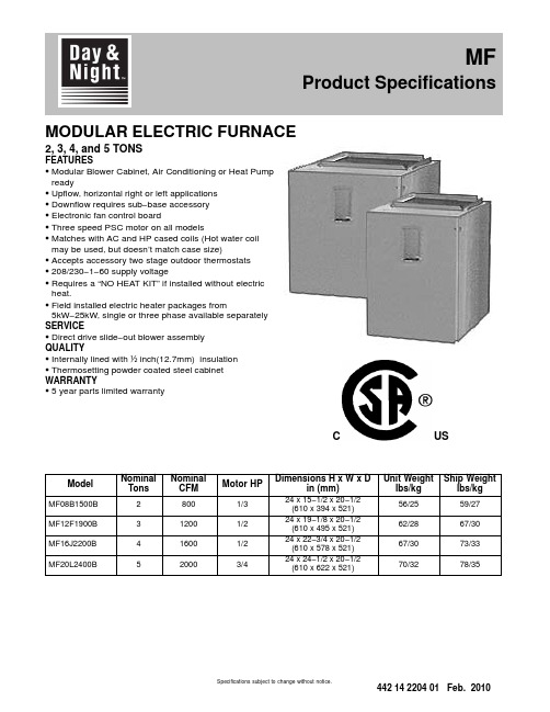
MODULAR ELECTRIC FURNACE2, 3, 4, and 5 TONSFEATURESS Modular Blower Cabinet, Air Conditioning or Heat Pump readyS Upflow, horizontal right or left applicationsS Downflow requires sub−base accessoryS Electronic fan control boardS Three speed PSC motor on all modelsS Matches with AC and HP cased coils (Hot water coil may be used, but doesn’t match case size)S Accepts accessory two stage outdoor thermostatsS208/230−1−60 supply voltageS Requires a “NO HEAT KIT” if installed without electric heat.S Field installed electric heater packages from5kW−25kW, single or three phase available separately SERVICES Direct drive slide−out blower assemblyQUALITYS Internally lined with ½inch(12.7mm) insulationS Thermosetting powder coated steel cabinet WARRANTYS5 year parts limited warrantyUSCModel NominalTons NominalCFM Motor HPDimensions H x W x Din (mm)Unit Weightlbs/kgShip Weightlbs/kgMF08B1500B28001/324 x 15−1/2 x 20−1/2(610 x 394 x 521)56/2559/27MF12F1900B312001/224 x 19−1/8 x 20−1/2(610 x 495 x 521)62/2867/30MF16J2200B416001/224 x 22−3/4 x 20−1/2(610 x 578 x 521)67/3073/33MF20L2400B520003/424 x 24−1/2 x 20−1/2(610 x 622 x 521)70/3278/35MF Product SpecificationsSpecifications subject to change without notice.UNIT SPECIFICATIONS − ELECTRIC FURNACEModel Number MF08B1500B MF12F1900B MF16J2200B MF20L2400B Application Upflow / Horizontal / Downflow *Electrical Volts−Phase−Hz.208/230-1-60Data**Minimum Circuit Ampacity 3.1 3.6 3.67.5 Time Delay Fuse (Amps)15Max Fuse or Breaker Size(Amps)15Blower Size DD10 − 7DD10 − 8DD10 − 9DD10 − 9 Data Horsepower−Speed1/3 − 31/2 − 31/2 − 33/4 − 3 Full Load Rated (Amps) 2.5 2.9 2.9 6.0 Transformer40 VAWeight Unit / Shipping Lbs (Kg)56/59 (25/27)62/67 (28/30)70/78 (32/35)70/78 (32/35) * Accessory subbase kit required for downflow application**Disregard if electric heat is added. Refer to Electric Heat table.MODEL NUMBER IDENTIFICATION GUIDEPRODUCT FAMILYM = MODULAR M F12F1900B2SERIESSALES CODES B = MODULAR BLOWER (115V)F = MODULAR ELECTRIC FURNACE (208/230V)V = MODULAR VARIABLE SPEED BLOWER (208/230V)FIELD INSTALLED HEATER NOMINAL CFM RANGE COIL WIDTH MATCH 08 = 800B15 = 15-1/2 Cabinet 12 = 1200F19 = 19-1/8 Cabinet 16 = 1600J22 = 22-3/4Cabinet 20 = 2000L24 = 24-1/2CabinetAirflow based on no coil, no filter, no electric heat (pre−accessory external static pressure). When heaters, filters, hori-zontal drain pan and/or downflow subbase are installed in an application, airflow must be re−calculated by adding the heater static, filter static, and coil static pressures (provided in the following tables) to the pre−accessory external static amount. See Coil Specification Sheet. Add.10 for Horizontal Drain Pan Kit. Add .20 for Downflow Subbase Kit.AIRFLOW IS BLOWER ONLY, NO COIL ATTACHEDMF08ESP in wcSPEED VOLTS0.20.30.40.50.60.70.8Low 230v102910201007985960915862 208v872860845825797765721Med 230v1286127012541220118011251058 208v111311051091107010421000947High 230v1500147014321380131512501168 208v1317130512861255122011701008MF12ESP in wcSPEED VOLTS0.20.30.40.50.60.70.8Low 230v973975979979973955931 208v811815816810797780749Med 230v1284129513011305130212801246 208v1084108410841090108910651030High 230v1663167016711655163115851519 208v1383138513901390138313651328MF16ESP in wcSPEED VOLTS0.20.30.40.50.60.70.8Low 230v1020101510091002991975950 208v858845830815801780749Med 230v1379138513861379136413431309 208v1156115411491144113411201098High 230v1776178217831765173816981643 208v1496149614961495149514701433MF20ESP in wcSPEED VOLTS0.20.30.40.50.60.70.8Low 230v1492149514921475145113951308 208v1246124512381225120311751125Med 230v1969195519351890181817001570 208v1641164016331615158415101406High 230v2696260024922350219220201844 208v2417235522872200209219401774FILTER STATIC PRESSURE DROPWASHABLEFILTER SIZENOMINALDISPOSABLEFILTER SIZECFMMODEL600800100012001400160018002000 MF0814 1/4 x 201/414 x 200.050.090.130.19−−−−−−−−−−−−MF1217 3/4 x 20 1/418 x 20−−−−−−−−0.090.120.170.22−−−−−−MF1621 1/4 x 20 1/420 x 20−−−−−−−−−−−−−−0.120.150.19−−−MF2024 3/4 x 20 1/424 x 20−−−−−−−−−−−−−−0.090.110.140.18HEATER STATIC TABLE HEATER KW / STATIC DROPSingle−PhaseCFM EHIA05EHIA07EHIA10EHIA15EHIA20EHIA25 6000.010.010.01-- ---- ---- --7000.010.010.01-- ---- ---- --8000.010.010.010.01-- ---- --9000.010.010.010.01-- ---- --10000.010.010.010.010.02-- --11000.010.010.010.020.02-- --12000.010.010.010.020.02-- --13000.010.020.020.020.02-- --14000.010.020.020.020.030.03 15000.010.020.020.020.030.04 16000.010.020.020.030.030.04 17000.010.020.020.030.030.04 18000.010.020.020.030.040.04 19000.010.020.020.030.040.05 20000.010.020.020.030.040.05 Three−PhaseCFM-- ---- --EHIA10EHIA15EHIA20EHIA25 600-- ---- --0.01-- ---- ---- --700-- ---- --0.01-- ---- ---- --800-- ---- --0.010.01-- ---- --900-- ---- --0.010.01-- ---- --1000-- ---- --0.010.010.02-- --1100-- ---- --0.010.020.02-- --1200-- ---- --0.010.020.02-- --1300-- ---- --0.020.020.02-- --1400-- ---- --0.020.020.030.03 1500-- ---- --0.020.020.030.04 1600-- ---- --0.020.030.030.04 1700-- ---- --0.020.030.030.04 1800-- ---- --0.020.030.040.04 1900-- ---- --0.020.030.040.05 2000-- ---- --0.020.030.040.05 -- --DO NOT OPERATE IN THIS AREA CFM / KW LIMIT EXCEEDEDUNIT SPECIFICATIONS − No Heat KitNo Heat Kit Model Table 1Supply CircuitSupplyCircuitNo.HPMax.MotorAmpsMCABranchCircuitAMPMax Over-currentProtectionDevise(Amps)Recommended Volts Phase HertzSupply Wire75°C copperGround Wire# ofWiresWireSizeMax. Ft.Length# ofWiresMinWireSizeEHIA00KN10MF08*208160Single1/3 2.5 3.115214105114 230MF12*208160Single1/2 2.9 3.615214105114 230MF16*208160Single1/2 2.9 3.615214105114 230MF20*208160Single3/4 6.07.51521490114 230* Modular blower without electric heat Conversion: 1 foot = .305 metersTECHNICAL DATA Single Phase with Circuit BreakerMaximum RecommendedMCA OvercurSupply Wire Ground Nom.Supply Heater Max FLA Min Protective75 0 C. Copper WireHeater Supply Heati Heat kW Per Circuit kW Per Heater Motor Total Circuit Device# of Wire Max.# of MinModel VoltBTUH KW Element No.Circuit AMPS.AMPS.AMPS.Ampacity(AMPS.)Wires Size Length (Ft)Wires SizeEHIA05KB1024016378 4.8 4.8Single 4.820.0626.032.53528113110 20812283 3.6 3.6Single 3.617.3623.329.130210118110EHIA07KB10240245677.2 3.6Single7.230.0636.045.0452881110 20818425 5.4 2.7Single 5.426.0632.040.0402892110EHIA10KB10240327569.6 4.8Single9.640.0646.057.56026101110 208245677.2 3.6Single7.234.6640.650.86026115110EHIA15KB102404913414.4 4.8Single14.460.0666.082.5902411318Mult. 19.640.0646.057.56026101110Mult. 2 4.820.0020.025.025******** 2083685110.8 3.6Single10.851.9657.972.4802412818Mult. 17.234.6640.650.86026115110Mult. 2 3.617.3017.321.625210109110EHIA20KB102406551319.2 4.8Single19.280.0686.0107.51102213716Mult. 19.640.0646.057.56026101110Mult. 29.640.0040.050.0502873110 2084913414.4 3.6Single14.469.2675.294.010*********Mult. 17.234.6640.650.86026115110Mult. 27.234.6034.643.3452885110EHIA25KB102408189124 4.8Single24100.06106.0132.515021/017716Mult. 19.640.0646.057.56026101110Mult. 214.460.0060.075.0802412418 2086141818 3.6Single1886.5692.5115.71252116116Mult. 17.234.6640.650.86026115110Mult. 210.851.9051.964.9702690110TECHNICAL DATA Single−Phase with Terminal BlockMaximum RecommendedMCA OvercurSupply Wire Ground Nom.Supply Heater Max FLA Min Protective75 0 C. Copper WireHeater Supply Heati Heat kW Per Circuit kW Per Heater Motor Total Circuit Device# of Wire Max.# of MinModel VoltBTUH KW Element No.Circuit AMPS.AMPS.AMPS.Ampacity(AMPS.)Wires Size Length (Ft)Wires SizeEHIA05KN1024016378 4.8 4.8Single 4.820.0626.032.53528113110 20812283 3.6 3.6Single 3.617.3623.329.130210118110EHIA07KN10240245677.2 3.6Single7.230.0636.045.0452881110 20818425 5.4 2.7Single 5.426.0632.040.0402892110EHIA10KN10240327569.6 4.8Single9.640.0646.057.56026101110 208245677.2 3.6Single7.234.6640.650.86026115110TECHNICAL DATA Three Phase with Circuit BreakerMaximum RecommendedMCA OvercurSupply Wire Ground Nom.Supply Heater Max FLA Min Protective75 0 C. Copper WireHeater Supply Heati Heat kW Per Circuit kW Per Heater Motor Total Circuit Device# of Wire Max.# of MinModel VoltBTUH KW Element No.Circuit AMPS.AMPS.AMPS.Ampacity(AMPS.)Wires Size Length (Ft)Wires SizeEHIA10HB10240327569.6 3.2Single9.623.1629.136.44038117110 208245677.2 2.4Single7.220.0626.032.53538131110EHIA15HB102404913414.4 4.8Single14.434.7640.750.9603613218 2083685110.8 3.6Single10.830.0636.045.0453894110EHIA20HB102406551319.2 3.2Single19.246.2652.265.3703416518Mult. 1 6.415.4621.426.830310102110Mult. 212.830.8030.838.54038110110 2084913414.4 2.4Single14.440.0646.057.5603611718Mult. 1 4.813.3619.324.230310113110Mult. 29.626.7026.733.33538127110EHIA25HB1024081891244Single2457.8663.879.8803413518Mult. 1819.3625.331.63538134110Mult. 21638.5038.548.2503888110 20861418183Single1850.0656.070.0703415318Mult. 1616.7622.728.33031096110Mult. 21233.3033.341.74538102110Conversion: 1 foot = .305 metersHEATER STAGING Single−PhaseELECTRIC HEATER VOLTAGETOTAL HEAT KW1st STAGE KW (W1)2nd STAGE KW (W2) 208V240V208V240V208V240VEHIA05KB10208−240/1/60 3.6 4.8 3.6 4.8−−EHIA07KB10208−240/1/60 5.47.2 5.47.2−−EHIA10KB10208−240/1/607.29.67.29.6−−EHIA15KB10208−240/1/6010.814.47.29.6 3.6 4.8 EHIA20KB10208−240/1/6014.419.27.29.67.29.6EHIA25KB10208−240/1/6018247.29.610.814.4EHIA05KN10208−240/1/60 3.6 4.8 3.6 4.8−−EHIA07KN10208−240/1/60 5.47.2 5.47.2−−EHIA10KN10208−240/1/607.29.67.29.6−−Three−PhaseELECTRIC HEATER VOLTAGE TOTAL HEAT KW1st STAGE KW (W1)2nd STAGE KW (W2)208v240v208v240v208v240v EHIA10HB10208−240/3/607.29.67.29.6−−EHIA15HB10208−240/3/6010.814.410.814.4−−EHIA20HB10208−240/3/6014.419.2 4.8 6.49.612.8 EHIA25HB10208−240/3/601824681216Conversion: 1 foot = .305 metersHEAT STRIP STAGINGSingle−Stage OperationTwo−Stage Capable Three−Stage Capable (with ODTS only)(no staging − all electric heat together)Single−Phase EHIA05KB / KNEHIA15KBEHIA20KBEHIA25KBEHIA25KB EHIA07KB / KNEHIA10KB / KNEHIA15KBEHIA20KBEHIA25KBThree−Phase EHIA10HB EHIA10HBEHIA20HBEHIA25HB EHIA15HB EHIA15HBEHIA20HB EHIA20HBEHIA25HB EHIA25HBACCESSORIESModel Description Used with MF ModelEHIA00KN10No Heat Kit08, 12, 16, 20 EHIA05KB10 5 kW 1-Phase w/C.B.08, 12, 16, 20 EHIA05KN10 5 kW 1-Phase w/T.B.08, 12, 16, 20 EHIA07KB107.5 kW 1-Phase w/C.B.08, 12, 16, 20 EHIA07KN107.5 kW 1-Phase w/T.B.08, 12, 16, 20 EHIA10KB1010 kW 1-Phase w/C.B.08, 12, 16, 20 EHIA10KN1010 kW 1-Phase w/T.B.08, 12, 16, 20 EHIA15KB1015 kW 1-Phase w/C.B.08, 12, 16, 20 EHIA20KB1020 kW 1-Phase w/C.B.12, 16, 20 EHIA25KB1025 kW 1-Phase w/C.B.16, 20 EHIA10HB1010 kW 3-Phase w/C.B.12, 16, 20 EHIA15HB1015 kW 3-Phase w/C.B.12, 16, 20 EHIA20HB1020 kW 3-Phase w/C.B.16, 20 EHIA25HB1025 kW 3-Phase w/C.B.16, 20KN = 1-phase T.B. = terminal blockKB = 1-phase C.B. = circuit breakerHB = 3-phase SINGLE POINT WIRING KITModel DescriptionUsed withHeater size AMFK20SPA Single Point Wiring Kit (4-pole)15-20 kW AMFK30SPA Single Point Wiring Kit (6-pole)25 kW OUTDOOR THERMOSTATModel DescriptionUsed withHeater size AMF002OTA2-Stage ODTS15 kW andabove DOWNFLOW KITModel DescriptionUsed withMF Model AMF008DFB1Downflow kit08 AMF012DFB1Downflow kit12 AMF016DFB1Downflow kit16 AMF020DFB1Downflow kit20International Comfort Products, LLC Lewisburg, Tennessee 37091 U.S.A.。
日立变频空调操作手册说明书
IOD-40249/2016OPERATION MANUALMODELSAir Handling UnitFXTQ09TAVJUA FXTQ09TAVJUD FXTQ12TAVJUA FXTQ12TAVJUD FXTQ18TAVJUA FXTQ18TAVJUD FXTQ24TAVJUA FXTQ24TAVJUD FXTQ30TAVJUA FXTQ30TAVJUD FXTQ36TAVJUA FXTQ36TAVJUD FXTQ42TAVJUA FXTQ42TAVJUD FXTQ48TAVJUA FXTQ48TAVJUD FXTQ54TAVJUA FXTQ54TAVJUD FXTQ60TAVJUAFXTQ60TAVJUDSYSTEM Inverter Air ConditionersRead these instructions carefully before installation. Keep this manual in a handy place for future reference. This manual should be left with the equipment owner.Lire soigneusement ces instructions avant l’installation.Conserver ce manuel à portée de main pour référence ultérieure. Ce manuel doit être donnéau propriétaire de l’équipement.Lea cuidadosamente estas instrucciones antes de instalar.Guarde este manual en un lugar a mano para leer en caso de tener alguna duda. Este manual debe permanecer con el propietario del equipo.•Do not allow children to play on or around the unit to prevent injury.•The heat exchanger fins are sharp enough to cut. To avoid injury, wear gloves or cover the fins while work-ing around them.•Do not put a finger or other objects into the air inlet or air outlet. The fan is rotating at high speed and will cause injury.•Check the unit foundation for damage on a continu-ous basis, especially if it has been in use for a long time. If left in a damaged condition the unit may cause injury.•Placing a flower vase or other containers with water or other liquids on the unit could cause a shock or fire if a spill occurs.•Never touch the internal parts of the controller. Do not remove the front panel because some parts in-side are dangerous to touch. To check and adjustinternal parts, contact your dealer.•Do not use the heat pump for any other purposes other than comfort cooling or heating. Do not use the unit for cooling precision instruments, food, plants, animals or works of art.•Do not place items under the indoor unit as they may be damaged by condensates that may form if the humidity is above 80% or if the drain outlet gets blocked.•Before cleaning, stop the operation of the unit by turning the power off or by pulling the supply cord out from its receptacle. Otherwise, an electric shock and injury may result.•Do not wash the heat pump with excessive water. An electric shock or fire may result.•Avoid placing the controller in a spot splashed with water. Water entering the controller may cause an electric shock or damage the internal electronic parts.•Do not operate the heat pump when using a room fumigation type of insecticide. Failure to observe this could cause the chemicals to be deposited in the unit and can endanger the health of those who are hyper-sensitive to chemicals.•The appliance is not intended for use by young chil-dren or infirm persons without supervision.•The remote controller should be kept away from chil-dren so they cannot play with it.•Consult with the installation contractor for cleaning.•Incorrect cleaning of the inside of the heat pump could make the plastic parts break and cause water leakage or electric shock.•Do not touch the air inlet or aluminum fin of the heat pump as they can cut and cause injury.•Do not place objects in direct proximity of the out-side unit. Do not let leaves and other debris accumu-late around the unit. Leaves are a hotbed for small animals which can enter the unit. Once inside the unit, animals can cause the unit to malfunction and cause smoke or fire when they make contact withelectrical parts.•Never press the button of the remote controller with a hard, pointed object. The remote controller may be damaged.•Never pull or twist the electric wire of the remote con-troller. It may cause the unit to malfunction.•Do not place appliances that produce open flames in places that are exposed to the air flow of the unit or under the indoor unit. It may cause incomplete com-bustion or deformation of the unit due to the heat.•Do not expose the controller to direct sunlight. The LCD display can become discolored and may fail to display the data.•Do not wipe the controller operation panel with ben-zene, thinner, chemical dust cloth, etc. The panel may get discolored or the coating can peel off. If it is heavily dirty, soak a cloth in water-diluted neutral detergent, squeeze it well and wipe the panel clean.Then wipe it with another dry cloth.•Dismantling of the unit, disposal of the refrigerant, oil, and additional parts, should be done in accor-dance with the relevant local, state, and national regu-lations.•Operate the heat pump in a sufficiently ventilated area and not surrounded by obstacles. Do not use the heat pump in the following places.a.Places with a mist of mineral oil, such as cuttingoil.b.Locations such as coastal areas where there is alot of salt in the air.c.Locations such as hot springs where there is a lotof sulfur in the air.d.Locations such as factories where the power volt-age varies a lot.e.In cars, boats, and other vehicles.f.Locations such as kitchens where oil may splat-ter or where there is steam in the air.g.Locations where equipment produces electromag-netic waves.h.Places with an acid or alkaline mist.i.Places where fallen leaves can accumulate orwhere weeds can grow.•Do not attempt to do electrical work or grounding work, unless you are licensed to do so. Consult with your dealer for electrical work and grounding work.•Pay attention to operating sound. Be sure to use the following places:a.Places that can sufficiently withstand the weightof the heat pump yet can suppress the operat-ing sound and vibration of the heat pump.b.Places where warm air from the air outlet of theoutside unit or the operating sound of the out-side unit does not annoy neighbors.•Consult your dealer if the heat pump in operation gen-erates unusual noise.•Make sure that the drainpipe is installed properly to drain water. If no water is discharged from the drain-pipe while the heat pump is in the cooling mode, the drainpipe may be clogged with dust or dirt and water leakage from the indoor unit may occur. Stop oper-ating the heat pump and contact your dealer.2.3.MAINTENANCE•Only a qualified person is allowed to perform mainte-nance without daily maintenance.•Before touching any of the connection wirings, be sure to turn off all power supply switches.•For installation of optional parts, only a qualifited person is allowed to do so.Be sure to use optional parts specified by the manufac-turer. Installation in your own manner may result in wa-ter leakage, electric shock or fire.•Do not use flammable material (e.g. hair-spray or insec-ticide) near the product.•Only proceed with the unit cleaning after stopping the operation and turning the power supply off.Failure to do so may result in electric shocks or injury.•Do not wash the heat pump or air handler with water.Failure to do so may result in an electric shock.•Consult with installation contractor for cleaning the inside of the air handler.Wrong cleaning procedures may break plastic parts or cause water leakage or electric shock.•Use a stable prep stand.Pay extra attention when cleaning the air handler. (Maintenance and inspection)•Clean the drain pan periodically. The drain pipes clogged with dust will cause water leakage.•For cleaning, consult with your Daikin dealer. (Before each season when cooling or heating is required, clean the air handler.)•If the area around the indoor unit is very dusty, use a dust proof cover (local procurement).(Cleaning the inside of the indoor unit)•It is necessary to clean the inside of the indoor unit peri-odically.Since the cleaning requires special technologies, requesta Daikin dealer to clean them.(Electric heater replacement interval)•The electric heater should be replaced every ten years.This replacement interval is a guideline for ensuring safe and trouble-free operation of the product for many years. (Cleaning the air filter)•The air filter is an optional accessory.EXPLANATION:•Removing the air filter except when cleaning the air han-dler may result in accidents.•Replace the filter when one of the following messages displayed on the bottom of remote controller screen.- Time to clean filter & element- Time to clean filter•If using the air handler under very dusty environment, increase the frequency of air filter cleaning.•Reset the filter sign on main menu of remote controller.Refer an operation manual of remote controller for de-tail.•Consult dealer to change filter setting time to display fil-ter change alarm on remote controller screen. (The de-fault factory setting is 2500 hours.)•There are the following time, display pattern: 1250, 2500, 5000, 10000.•Do not allow the indoor unit to get wet as it may cause an electric shock or fire._______________________________________________ 4. PRECAUTIONSIf the following phenomenon occurs, contact your dealer.•Any abnormalities in the operation of the heat pump or air handler such as smoke or fire could result in severe injury or death.Turn off the power and contact your dealer immediately for instructions._______________________________________________ Phenomenon•The unit may operate with the airflow rate at high speed even though the airflow rate was set to low speed using the remote controller during ELECTRIC HEATER opera-tion.Take the following actions before contact.Check to see if an optional electric heater is installed.The unit operates with the airflow rate at high speed dur-ing ELECTRIC HEATER operation regardless of the re-mote controller airflow rate setting or display.Phenomenon•The safety devices such as fuse, breaker, ground fault interrupter, etc. often operate or operations of the opera-tion switch are unstable.Take the following actions before contact.Turn off the switch.•If the ON/OFF switch does not properly work, Take the following actions before contact.Turn off the main power switch.Phenomenon•Water leaks out from the air handle r.Take the following actions before contact.Stop the operation.Phenomenon•Error message is displayed. See the remote controller operation manual for details.Inform the dealer of the details being displayed on the remote controller.。
Hitachi 新壁挂式空调说明书

New TZ, smart comfort ina compact unit· Compact and elegant design with only 779mm wide · Simple installation, easy maintenance· B uilt-in WLAN for internet and voice control· Infrared Sky Controller· Cleaner air with PM2,5 filter· S uper Quiet! Only 20dB(A)· M ore comfort with Aerowings· H igh energy savings Wall-mounted TZ Super-compact Inverter · R32 RefrigerantNew Wall-mounted TZ super-compactONLY779mmPM2,5Particulate matter (PM2,5) can be found suspended in the air, including dust, dirt, smoke and liquid droplets. The filter can catch PM2,5 particles including hazardous pollutants as well as house dust and pollen and it is able to maintain clean the air of the room.New super-compact designThe new compact design of the indoor units have a width of just 779 mm. This allows for more installation possibilities, including the limiting space above a door .Meticulously designed for both installer and user benefit, installation time of the new TZ has been dramatically decreased.The inner workings of the unit have also beenredesigned to make maintenance quicker and easier . Electronics and wiring components are now on just one side of the unit to simplify maintenance.1324Comfort that goes on and on with Shower Cooling.When the Aerowings twin blades direct air towards the ceiling they create the Shower Cooling effect. This ensures cool air is evenly distributed throughout the room and you can stay comfortable without experiencing continuous direct cooling.Panasonic Air Conditioners with Aerowings feature and super-high fan speed to produce bigger air volume.Built-in WLAN and compatible with Voice AssistantReady to connect the unit to internet to be controlled by smartphone with Panasonic Comfort Cloud App. Control, monitor, easy schedule with easy interface.By connecting Panasonic Comfort Cloud the unit can be managed by the Google Assistant or Amazon Alexa*.* A mazon, Alexa and all related logos are trademarks of , Inc. or its affiliates Google, Android, Google Play and Google Home are trademarks of Google LLC.Stylish infrared controlEnjoy innovative design at your fingertips with the new stylish and sleek Backlit Sky Controller . Bigger screen and easier to use.AerowingsTo increase comfort level, TZ indoor units include Aerowings.Superior airflow control.Aerowings features two independent blades that give you more control over the direction of the airflow.Without Aerowings, with directairflow, the target never changes, so you can easily begin to feel too cold as you are subjected to the continuous icy blast.The choice for the narrow spaces in your home. New TZ with R32 refrigerant powerful and efficient.conditioner’s indoor operating noise has been reduced as the Inverter constantly varies its output power to enable more precise temperature control.* 2,5 and 3,5kW models: In the Quiet Mode during cooling operation with low fan speed.WLAN compatible with Voice AssistantWith optional CZ-TACG1 and Panasonic Comfort Cloud app in your Smartphone manage all functions up to 200 units, have access to energy statistics, set up advance scheduling and define different access rights to other users. This works with Google Assistant and Amazon Alexa.** G oogle, Android, Google Play and Google Home are trademarks of Google LLC. Amazon, Alexa and all related logos are trademarks of , Inc. or its affiliates. Availability of Voice Assistant services varies depending on Country and Language. More information about set up procedures: https:///connectivity/application.html.New, super-compact units, redesigned for simple installation and maintenance1. Stronger installation plate.The new models feature a stronger, solid installation plate that provides more stability and strength. For uneven surfaces, there are 2additional screws to ensure a neat and secure installation .2. One-piece front grille.The new model comes with a one-piece front grille design to makeservicing easier . First, open the intake grille and remove the screws. Next, slide the three slider locks and remove the front grille.3. Built-in support holder .The new model features a built-in support holder, making installation easier and providing convenience and workspace improvements.4. Easy access to drain hose & piping connection.With larger piping space, pipes and insulations are securely and neatly hidden.With the new visible piping storage, pipes can easily be inspected for leaks without lifting the unit.5. Easy wire insertion & tightening.The new models have combined 2 wire inserts into 1, ensuring front visibility and convenience while inserting wires from the back.6. Easy removal of PCB.PCB removal is achieved in just 4 easy steps. Simply remove the control board cover, disconnect all connectors from the indicator,disconnect all connectors and pull out the main PCB.7. Easy / hidden installation of the WLAN adapter .The latest model features a dedicated space for a network adapter . Easy to plug in, the guided wire slots allow for clear, easy installation and can be neatly tucked away - simple and out of sight!* O nly for models without built-in network adapter .8. Cross flow fan removal.The new models are carefullydesigned to make removal of cross flow fans easier compared to the previous models, saving valuable time.Additional screwholeInstallation plate: Strong and solid.Single tunnel: easy wire insert.One-piece front grille: Easy removal.Convenient installation and serviceability.Piping storage: 15 % larger .Simple steps for PCB removal.Bigger diameter Ø100.Bigger working space.Screw holder for uneven surface (screws not provided).Bigger working space for wiring connection.Slider locks: Easy to unlock / lock.w w w .e g g e a s s o c i a t s .n e tR2 ROTARYCOMPRESSOR20dB(A)BMS CONNECTIVITY5PM2,5 FILTER AEROWINGS R22/R410A RENEWALR22R410AR32BUILT-IN WLAN4,60 SCOPA ++7,00 SEERA ++R32INTEGRATIONTO P LINKD u e t o t h e o n g o i n g i n n o v a t i o n o f o u r p r o d u c t s , t h e s p e c i f i c a t i o n s o f t h i s c a t a l o g u e a r e v a l i d b a r r i n g t y p o g r a p h i c e r r o r s , a n d m a y b e s u b j e c t t o m i n o r m o d i f i c a t i o n s b y t h e m a n u f a c t u r e r w i t h o u t p r i o r w a r n i n g i n o r d e r t o i m p r o v e t h e p r o d u c t . T h e t o t a l o r p a r t i a l r e p r o d u c t i o n o f t h i s c a t a l o g u e i s p r o h i b i t e d w i t h o u t t h e e x p r e s s a u t h o r i s a t i o n o f P a n a s o n i c M a r k e t i n gE u r op e G m b H .New Wall-mounted TZ Super-compact Inverter • R32 RefrigerantOur heat pumps containing the refrigerant R32 show a drastic reduction in the value of Global Warming Potential (GWP) compared with R410A refrigerant. — Seasonal efficiency in cooling will bring you saving all year while heating. Energy efficiency rank from A+++ to D. — Seasonal efficiency in heating will bring you saving all year while heating. Energy efficiency rank from A+++ to D. — Inverter Plus System classification highlight the Panasonic highest performing systems. — Panasonic R2 Rotary Compressor . Designed to withstand extremeconditions, it delivers high performance and efficiency. — Dust Collection Filter . This filter collects and retain particles suspended on the air, as result the air is cleaner in the room. — With Super Quiet technology our devices are much more quiet than a library (30dB(A)). — More comfort with Aerowings. Direct airflow to ceiling to create shower cooling effect by twin flap built in indoor . — More comfort with Aerowings. Direct airflow to ceiling to create shower cooling effect by twin flap built in indoor . — The Panasonic renewal system allows good quality existing R410A or R22 pipe work to be re-used whilst installing new high efficiency R32 systems. — The Panasonic renewal system allows good quality existing R410A or R22 pipe work to be re-used whilst installing new high efficiency R32 systems. — The communication port can be integrated into the indoor unit and provides easy connection to, and control of, your Panasonic heat pump to your home or building management system. — This unit is ready to connect to internet and be managed by smartphone, with a powerful and user friendly App to manage the comfort wherever you are. — Communication port to integrate the unit to home and building management systems most known standards. — 5 Years Warranty. We guarantee the outdoor unit compressors in the entire range for five years.1) EER and COP calculation is based in accordance to EN14511. 2) Energy Label Scale from A+++ to D. 3) The annual energy consumption is calculated in accordance to EU/626/2011. 4) The sound pressure of the indoorunit shows the value measured of a position 1m in front of the main body and 0,8m below the unit. For outdoor unit 1m in front and 1m in rear side of main body. The sound pressure is measured in accordance with JIS C 9612. Q-Lo: Quiet mode. Lo: The lowest set fan speed. 5) Add 70mm for piping port. 6) When installing the outdoor unit at a higher position than the indoor unit.SEER and SCOP: For KIT-TZ20-WKE and KIT-TZ25-WKE. SUPER QUIET: For KIT-TZ20-WKE, KIT-TZ25-WKE and KIT-TZ35-WKE. INTERNET CONTROL: Built-in WLAN.KitKIT-TZ20-WKEKIT-TZ25-WKE KIT-TZ35-WKE KIT-TZ42-WKE KIT-TZ50-WKE KIT-TZ60-WKE KIT-TZ71-WKE Power source V230230230230230230230Air volumeCool / Heat m³/min 10,3 / 10,811,0 / 11,511,8 / 12,312,5 / 13,212,5 / 13,220,9 / 21,922,1 / 22,9Moisture removal volume L/h 1,31,52,02,42,83,34,1Sound pressure 4)Cool (Hi / Lo / Q-Lo)dB(A)37 / 25 / 2040 / 26 / 2042 / 30 / 2044 / 31 / 2944 / 37 / 3345 / 37 / 3447 / 38 / 35Heat (Hi / Lo / Q-Lo)dB(A)38 / 26 / 2240 / 27 / 2242 / 33 / 2244 / 35 / 2844 / 37 / 3345 / 37 / 3447 / 38 / 35Dimension H x W x Dmm 290 x 779 x 209290 x 779 x 209290 x 779 x 209290 x 779 x 209290 x 779 x 209302 x 1 102 x 244302 x 1 102 x 244Net weight kg888881313Outdoor unit CU-TZ20WKE CU-TZ25WKE CU-TZ35WKE CU-TZ42WKE CU-TZ50WKE CU-TZ60WKE CU-TZ71WKE Air volume Cool / Heatm³/min 29,7 / 29,730,0 / 28,928,7 / 29,730,4 / 30,832,7 / 32,734,0 / 34,044,7 / 45,9Sound pressure 4)Cool / Heat (Hi)dB(A)46 / 4747 / 4848 / 5049 / 5148 / 4949 / 5152 / 54Dimension 5)H x W x Dmm 542 x 780 x 289542 x 780 x 289542 x 780 x 289542 x 780 x 289619 x 824 x 299619 x 824 x 299695 x 875 x 320Net weight kg 24253131363650Pipe length rangem 3 ~ 15 3 ~ 15 3 ~ 15 3 ~ 15 3 ~ 20 3 ~ 30 3 ~ 30Elevation difference (in/out) 6)m 15151515151520Refrigerant (R32) / CO 2 Eq.kg / T 0,54 / 0,3650,67 / 0,4520,77 / 0,5200,79 / 0,5331,14 / 0,7701,22 / 0,8241,32 / 0,891Operating rangeCool Min ~ Max °C -10 ~ +43-10 ~ +43-10 ~ +43-10 ~ +43-10 ~ +43-10 ~ +43-10 ~ +43Heat Min ~ Max°C-15 ~ +24-15 ~ +24-15 ~ +24-15 ~ +24-15 ~ +24-15~+24-15~ +24NEW2020Built-in WLANPanasonic Comfort Cloud for internet control.Accessories CZ-CAPRA1RAC interface adapter for integration into P-LinkAccessories CZ-RD514CWired remote controller for Wall-mounted and Floor ConsoleE U -LF L T R A C T Z 0220To find out how Panasonic cares for you, log on to www.aircon.panasonic.eu/IE_en/+353 (0)1 4195313+353 (0) 876005031Heating & Cooling SolutionsPanasonic Ireland. A branch of Panasonic Marketing Europe GmbH Unit 1, The Courtyard, Kilcarbery Business ParkNangor Road, Dublin 22。
日立空调说明书 RAS-25YHA RAC-25YHA RAS-35YHA RAC-35YHA
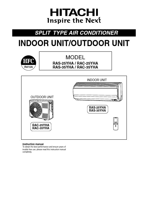
MODELRAS-25YHA / RAC-25YHARAS-35YHA / RAC-35YHAInstruction manualTo obtain the best performance and ensure years oftrouble free use, please read this instruction manualcompletely.INDOOR UNIT/OUTDOOR UNIT– 2 –• Please read the “Safety Precaution” carefully before operating the unit to ensure correct usage of the unit.• Pay special attention to signs of “ Warning ” and “ Caution ”. The “Warning” section contains matters which, if not observed strictly, may cause death or serious injury. The “Caution” section contains matters which may result in serious consequences if not observed properly. Please observe all instructions strictly to ensure safety.• • Please keep this manual after reading.– 3 –– 4 –NAMES AND FUNCTIONS OF EACH PARTMODEL NAME AND DIMENSIONSAir filterTo prevent dust from coming into the indoor unit.(Refer page 16)Front panelIndoor unit indicatorsLight indicator showing the operating condition.(Refer page 5)Horizontal deflector Vertical deflector (Air Outlet)(Refer page 15)Remote controllerSend out operation signal to the indoor unit. So as to operate the whole unit.(Refer page 6)About the outdoor unit:• When “Stop” is selected during operation of the indoor unit, the fan of the outdoor unit continuesturning for 10 to 60 seconds to cool the electric parts down.• In heating operation, condensate or water due to defrosting will flow. Do not cover the drain port of the outdoor unit because such water may freeze in the chilly area.• When the outdoor unit is hung on the ceiling, instal the bush and drain pipe on the drain port and drain-water.– 5 –NAMES AND FUNCTIONS OF EACH PART FILTER LAMP (Green)When the device is operated for a total of about 200 hours, the FILTER lamp lights indicates that it isto clean the filter.The lamp goes out when the(AUTO SWING)” button is pressed while the OPERATION LAMP (Yellow)This lamp lights during operation.The OPERATION LAMP flashes in the following cases during heating.(1) DURING PREHEATINGFor about 2-3 minutes after starting up.(2) DURING DEFROSTINGDefrosting will be performed about oncean hour when frost forms on the heat exchanger of the outdoor unit, for 5-10 minutes each time.Use this switch to start and stop when the remote controller does not work.This temporary operation will be at the most recent setting made. (The unit will immediately go into automatic operation once power is switched on. The power is saved by turning off the power switch (or the circuit breaker when the power is supplied from the outdoor unit).Attaching the air cleansing and deodorizing filters (Accessories) to the filter frame.• Attach the air cleansing and deodorizing filters to the frame by gently compress its both sides and release after insertion into filter frame.• The cooling capacity is slightly weakened and the cooling speed becomes slower when the air cleansing and deodorizing filters are used.• Air cleansing and deodorizing filters can be used for about 1 year. When you want to renew it, please ask your sales agent.Attaching the negative ion stick to the filter frameto push up the upper hooks.Lower hookNAMES AND FUNCTIONS OF EACH PARTREMOTE CONTROLLER• This controls the operation of the indoor unit. The range of control is about 7 meters. If indoor lighting is controlled electronically, the range of control may be shorter.This unit can be fixed on a wall using the fixture provided. Before fixing it, make sure the indoor unit can be con-trolled from the remote controller.• Handle the remote controller with care. Dropping it or getting it wet may compromise its signal transmission ca-pability.• After new batteries are inserted into the remote controller, the unit will initially require approximately 10 seconds to respond to commands and operate.– 6 –– 7 –VARIOUS FUNCTIONSAUTOMATIC OPERATIONThe device will automatically determine the mode of operation, HEAT or COOL depending on the initial room temperature. The selected mode of operation will change when the room temperaturevaries varies.• If there is a power failure, operation will be automatically restarted when the power is resumed with previous operation mode and airflow direction.(As the operation is not stopped by remote controller.)• If you intend not to continue the operation when the power is resumed, switch off the power supply.When you switch on the circuit breaker, the operation will be automatically restarted with previous operation mode and airflow direction.Note: 1. If you do not require Auto Restart Control, please consult your sales agent. 2. Auto Restart Control is not available when Timer or Sleep Timer mode is set.HEATING OPERATION• Use the device for heating when the outdoor temperature is under 21°C.When it is too warm (over 21°C), the heating function may not work in order to protect the device.• In order to keep reliability of the device, please use this device above -10°C of the outdoor temperature.– 8 –– 9 –DEHUMIDIFYING OPERATION• Dehumidifying takes place with a target temperature which is slightly lower than the room temperature setting. (However, target temperature is 16°C for a temperature setting of 16°C.)If the room temperature becomes lower than the target value, operation stops. If the room temperature be-comes higher than the target value, operation restarts.• The preset room temperature may not be reached depending on the number of people present in the room or other room conditions.COOLING OPERATION– 10–– 11–FAN OPERATIONFAN SPEED (AUTO)– 12–HOW TO SET THE TIMER– 13–• The timer may be used in three ways: off-timer, on-timer and ON/OFF (OFF/ON)-timer. Set the current time at first because it serves as a reference.• button is order to use the same settings next time.– 14–– 15–HOW TO EXCHANGE THE BATTERIES IN THE REMOTE CONTROLLERPush and pull to the direction of arrow.the blade is marked.the blade is marked.MAINTENANCE– 16–– 17–– 18–INFORMATIONREGULAR INSPECTIONPLEASE CHECK THE FOLLOWING POINTS EVERY EITHER HALF YEARL Y OR YEARL Y . CONTACT YOUR SALES AGENT SHOULD YOU NEED ANY HELP .CONDITIONCHECK THE FOLLOWING POINTS• Do the batteries need replacement?• Is the polarity of the inserted batteries correct?• Is the air filter blocked with dust?• Is the set temperature suitable?• Have the top and bottom air deflectors been adjusted to their correct positions according to the operation mode selected?• Are the air inlets or air outlets of indoor and outdoor units blocked?• Is the fan speed “LOW”?AFTER SALES SERVICE AND WARRANTY• Is the fuse all right?• Is the voltage extremely high or low?• Is the circuit breaker “ON”?• Is the power plug inserted?• Do you have any power cut?When it does not operate.When it does not cool well.When it does not heat well.– The following phenomena do not indicate unit failure.If the remote controller is not transmitting a signal.(Remote controller display is dim or blank.)– 20–• If the unit still fails to operate normally after performing the above inspections, turn the circuit breaker off and contact your sales agent im-mediately.• Please contact your sales agent immediately if the air conditioner still fails to operate normally after the above inspections. Inform your agent of the model of your unit, production number, date of installation. Please also inform him regarding the fault.Please note:On switching on the equipment, particularly when the room light is dimmed, a slight brightness fluctuation may occur. This is of no consequence.The conditions of the local Power Supply Companies are to be observed.。
日立冷水机组说明书

HITACHI安装、使用、维护 说 明 书日 立 牌 水 冷 式 冷 水 机 组— 螺 杆 式 —注 意:在使用此冷水机组之前, 请仔细阅读该手册,并请 保存完好,供以后参考。
Model 型号RCU40WHZ-A(E) RCU50WHZ-A(E) RCU60WHZ-A(E) RCU80WHZ-A(E) RCU100WHZ-A(E) RCU120WHZ-A(E) RCU150WHZ-A(E) RCU180WHZ-A(E) RCU200WHZ-A(E) RCU220WHZ-A(E) RCU240WHZ-A(E)重 要 通 知z日立对产品的设计和性能将不断进行改良,规格如有更改,恕不另行通知。
z日立对每一个可能的情况导致有潜在的危险不作预测。
z没有书面允许,此说明书不得翻印。
z信号字句(危险、警告和小心)用于鉴定危险性的级别,有关各信号字句所提示的危险性解释如下:警 告可能导致严重个人受伤或死亡的直接危险。
危 险危险或不安全的操作可能导致严重个人受伤或死亡。
小 心危险或不安全的操作可能导致轻微个人受伤、产品或财物损害。
注 意:对使用或维修有帮助的资料。
z如有需要,请联络您所聘用的承建商或日立分销商。
z此水冷式冷水机组是根据以下温度设计,冷水机组应在此范围内使用: 工作范围 ( ℃)最高 最低 冷却水 出水温度 37 22冷冻水 出水温度 20 5z此说明书为水冷式冷水机组的永久部件,应妥善保存。
注:带液晶屏机组的液晶屏使用说明,请参考随机资料Z0011620《液晶屏使用说明书》。
z能效等级:上述数据依据GB 19577-2004 《水冷机组能效限定值及能源效率等级》。
目 录使用说明1.准备工作 (1)初步检查 (1)机组安装 (1)2.安装工作....................................... (6)电线连接 (6)工作范围 (9)水管接驳 (10)水质控制 (11)标准管路和接线 (12)3.运转试验 (13)准备工作 (13)运转试验 (14)试运转后的操作 (14)4.控制器设定 (15)5. 自动检查功能 (20)6.控制系统 (23)7.保养工作 (26)组件 (26)润滑 (26)沉渍 (26)冬季长时间停机 (27)春季初次启动 (27)零件更换 (27)冷媒循环 (27)压缩机的拆卸 (29)安全保护及控制器件的设定值 (30)正常操作压力 (31)8.故障寻找 (34)日立水冷式冷水机组型号:RCU40、50、60WHZ-A(E)使用说明指示灯:1.红灯指示正常运转状态。
日立风冷热泵空调说明书
安装、使用、维护说 明 书日立牌风冷单冷式冷水机组H 系列--螺 杆 式--Z0011312- 2008- B型号R22 R407CRCU40AHZ1 RCUG40AHZ1 RCU50AHZ1 RCUG50AHZ1 RCU60AHZ1 RCUG60AHZ1 RCU75AHZ1 RCUG75AHZ1 RCU100AHZ1 RCUG100AHZ1 RCU120AHZ1 RCUG120AHZ1 RCU150AHZ1 RCUG150AHZ1 RCU180AHZ1 RCUG180AHZ1 RCU200AHZ1 RCUG200AHZ1 RCU240AHZ1 RCUG240AHZ1 RCU270AHZ1 RCUG270AHZ1 RCU300AHZ1 RCUG300AHZ1 RCU330AHZ1 RCUG330AHZ1 RCU350AHZ1 RCUG350AHZ1 RCU360AHZ1 RCUG360AHZ1 RCU380AHZ1 RCUG380AHZ1 RCU400AHZ1 RCUG400AHZ1重要通知●日立对产品的设计和性能将不断进行改良,规格如有更改,恕不另行通知。
●日立对每一个可能的情况可引致有潜在的危险不作预测。
●没有书面允许,此说明书不得翻印。
●信号字句(危险,警告和小心)用于鉴别危险性的级别,有关各信号字句所提示的危险性解释 如下:: 可能导致严重个人受伤或死亡的直接危险。
: 危险或不安全的操作可能导致严重个人受伤或死亡。
: 危险或不安全的操作可能导致轻微个人受伤或产品或财物损害。
: 对使用或维修有帮助的资料。
●如有需要,请联络您所聘用之承建商或日立分销商。
●此说明书提供其他型号的风冷单冷式冷水机组的共同描述和资料。
●此风冷单冷式冷水机组是根据以下温度设计,冷水机组应在此范围使用:工作范围● 此说明书为风冷单冷式冷水机组的永久部件,应保留在冷水机组内。
● 下表为本说明书中所叙机组的能效等级汇总:机型能效 等级 机型能效等级机型 能效 等级机型 能效 等级RCU40AHZ1 4 RCU200AHZ1 3 RCUG40AHZ1 5 RCUG200AHZ14 RCU50AHZ1 3 RCU240AHZ1 3 RCUG50AHZ15 RCUG240AHZ1 4 RCU60AHZ1 3 RCU270AHZ1 3 RCUG60AHZ1 4 RCUG270AHZ1 4 RCU75AHZ1 3 RCU300AHZ1 3 RCUG75AHZ1 4 RCUG300AHZ1 4 RCU100AHZ1 3 RCU330AHZ1 3 RCUG100AHZ1 5 RCUG330AHZ1 4 RCU120AHZ1 3 RCU350AHZ1 3 RCUG120AHZ1 4 RCUG350AHZ1 4 RCU150AHZ1 3 RCU360AHZ1 3 RCUG150AHZ1 4 RCUG360AHZ1 4 RCU160AHZ1 3 RCU380AHZ1 3 RCUG160AHZ1 5 RCUG380AHZ1 4 RCU180AHZ1 3RCU400AHZ1 3 RCUG180AHZ1 4 RCUG400AHZ14*依据国家标准:GB19577-2004 作为能效等级判定。
- 1、下载文档前请自行甄别文档内容的完整性,平台不提供额外的编辑、内容补充、找答案等附加服务。
- 2、"仅部分预览"的文档,不可在线预览部分如存在完整性等问题,可反馈申请退款(可完整预览的文档不适用该条件!)。
- 3、如文档侵犯您的权益,请联系客服反馈,我们会尽快为您处理(人工客服工作时间:9:00-18:30)。
——目录——1.LONWORKS技术概况2.G/W协议转换器3.机组测的设定和接线4.试运行5.LONWORKS变量SNVT定义6.报警代码转换表1.LONWORKS技术概况美国Echelon公司1991年推出的LON技术,又称LONWORKS技术是计算机控制技术第三代的现场总线技术。
LONWORKS技术是一个实现控制网络系统的完整平台。
这些网络包括智能设备或节点。
括智能设备或节点与它们所处的环境进行交互作用,以及通过不同的通信介质与其它节点进行通信。
这种通信采用一种通用的、基于消息的控制协议-LONTALK协议。
由于LONTALK协议已固化在神经元芯片(微处理器)内,节点通过网络变量的形式交换信息,又有现成的网络管理工具进行网络管理。
所以建立一个LONWORKS控制网络在网络通讯上几乎不需要任何调试工作量。
LONWORKS技术的网络通信对用户是透明的,神经元芯片自动完成LONWORK S的所有七层的网络协议,用户所要作的只有两件事:第一件事是指定哪些信息是通过网络变量传递的,也就是定议网络变量;第二件事是指定信息传递传递的发起者和接收者,也就是做Binding(网络变量的捆绑)。
2.G/W协议转换器(其型号为HARC70-C)G/W协议转换器是日立公司提供的通信用网关设备(可简称G/W)。
是把广州日立冷机有限公司内部用的H-link通信协议转换成公开的LONTALK协议的设备。
是便于用户通过通信网络监控日立的冷水机组为目的开发的一种通信协议转换器。
1)系统构成方式以下是用G/W协议转换器联接到BMS(楼宇控制系统)系统时的系统构成简图。
对于构成系统的其它部品请参阅相应的使用说明书。
注意事项:1)冷水机组测的通信线上一定要加上附带的线圈和电容。
2)屏蔽线要采用D类接地标准备注:上位装置可使用LONWORKS /RS232C型的G/W(ECHELON制SLTA-10 通用的LONTALK 收发器等)及相应的软件。
2)G/W协议转换器结构说明以下是G/W协议转换器外部结构及说明.对于LED指示灯POW指示灯:灯亮表示有电源输入。
IRP指示灯:闪烁时表示处在与上位监控装置的通信当中,也就是表示LONWORKS通信线在工作中。
PAC指示灯:闪烁时表示处在与冷水机组的通信当中。
.对于5脚DSW拔动开关DSW-1:置于ON状态DSW-2~5:置于OFF状态注:根据5脚DSW拔动开关的以上设定进入正常运行状态,另外5 脚DSW拔动开关还用于自诊断(自诊断内容不在本资料范围内)。
.对于8脚DSW拔动开关DSW-1~4:置于OFF状态DSW-5:置于ON状态DSW-6~7:置于OFF状态注:根据8脚DSW拔动开关的以上设定进入正常运行状态,但此设定只对于早期的版本有效。
从P-1573版本开始不需要此设定,这时8脚DSW拔动开关全部置于OFF状态既可。
版本的标识在测盖的内侧。
.对于PSW按纽和七段码显示装置的作用请看试运行部分。
3)G/W协议转换器规格4)安装方式G/W协议转换器安装可垂直面上选择导轨和螺钉安装,但禁止水平安装。
安装尺寸如下所示。
5)配线说明G/W协议转换器要联接的配线有G/W协议转换器的电源线、G/W协议转换器的接地线、与上位监控装置的通信线、与冷水机组的通信线四种.G/W协议转换器电源线:无特殊要求,接线方法如下.G/W协议转换器接地线:要满足相关的接地标准,接线方法如下.G/W协议转换器与上位监控装置的通信线:通信用配线请使用ECHELON公司推荐的配线,也可以使用上位监控装置供应商指定的配线。
其接线方法如下:注:通信线无极性。
.G/W协议转换器与冷水机组的通信线:通信用配线请使用DC5V 0.75mm2的双绞线其接线方法如下:3.机组测的设定和接线1)机组测与其有关的设定及说明.冷水机组的地址设定:系统根据在操作基板上的拔动开关DSW3-8~10的设定来判断冷水机组的当前地址。
祥细的设定看下表:.机组启停控制模式设定:系统用操作基板上的开关SW6设定本体/远程控制模式。
开关置于上测为本体控制、置于下测为远程控制。
.机组远程控制模式设定:当操作基板上的开关DSW7-4设定为ON状态时系统选中通信控制(BMS控制)模式。
出厂设置为OFF。
.机组的通信端口设定:用控制基板(主控板)上的开关DSW设定通信端口的形式。
当用G/W协议转换器与机组通信时的正确设定为DSW-1:ON、DSW-2:OFF(此设定开关在CPU控制基板上)。
2)机组的通信线联接G/W协议转换器与机组的的H-Link通信线的联接方法如下:.通信线联接到冷水机组主控箱接线端子台的35、36号端子上。
适用的水冷式冷水机组的机型为RCU40SC2、RCU50SC2、RCU60SC2、RCU80SC2、RCU100SC2、RCU120SC2、RCU500SCZ、RCU600SCZ共八种机型。
.通信线联接到冷水机组主控箱接线端子台的34、35号端子上。
适用的水冷式冷水机组的机型为RCU150SC2、RCU180SC2、RCU200SC、RCU240SC、RCU300SCZ共五种机型。
.通信线联接到冷水机组主控箱接线端子台的39、40号端子上。
适用的水冷式冷水机组的机型为RCU400SCZ一种机型。
.通信线联接到冷水机组主控箱接线端子台的44、45号端子上。
适用的空冷式冷水机组的机型为RHU75ACZ、RHU100ACZ、RHU120ACZ、RHU150ACZ、RHU180ACZ、RHU200ACZ、RHU240ACZ、RHU300ACZ、RHU400ACZ、RCU75ACZ、RCU100ACZ、RCU120ACZ、RCU150ACZ、RCU180ACZ、RCU200ACZ、RCU240ACZ、RCU300ACZ共十七种机型。
注:其它的机型的接线方法请咨询相关技术服务人员。
4.试运行根据以下的步骤可进行试运行1)首先先确认系统配线的联接情况和拔动开关的设定情况。
确认无误后进入步骤2。
2)先给冷水机机组加电后再给G/W协议转换器加电。
在给G/W协议转换器加电时必须保证冷水机组的主控板上的处理器(微电脑)工作正常。
3)加电后G/W协议转换器开始工作(自检),根据G/W协议转换器的七段码显示可确认G/W协议转换器的工作状态。
4)确认联接的冷水机组数。
在七段码显示[00]状态下按下PSW按钮时七段码中显示确认的联接的冷水机组数。
5)以上完成了G/W协议转换器的试运行。
异常时的显示:当G/W协议转换器确认有异常时七段码的显示如下:5.LONWORKS变量SNVT定义LONWORKS变量简图※1:对于冷水温度的设定,连续容量控制时为出口温度,阶段容量控制时为入口温度。
※2:对于容量状态的显示只限于阶段容量控制,连续容量控制时不能显示机组的运行容量。
LONWORKS变量定义表LONWORKS网络变量的详细说明NV1 启停指令NETWORK INPUT SNVT_SWITCH NVICHILLERENABLE:这个LONWORKS输入网络变量使用于冷水机组的启停控制。
有效范围:V ALUE FIELD :NOT USEDSTATE FIELD :0/1 = 停止/运行NV2 冷水温度设定NETWORK INPUT SNVT_TEMP_P NVICOOLSETPT:这个LONWORKS输入网络变量使用于冷水机组冷水温度设定。
有效范围:4~25℃设定温度范围:1.0℃NV3 启停状态NETWORK OUTPUT SNVT_ SWITCH NVOONOFF:这个LONWORKS输出网络变量使用于冷水机组冷水启停状态的显示。
有效范围:0/1 = 停止/运行通信间隔:状态变化时输出刷新间隔:没有定时通信功能默认服务类型:AcknowledgedNV4 温度设定值NETWORK OUTPUT SNVT_ TEMP_P NVOACTIVELSETPT:这个LONWORKS输出网络变量使用于冷水机组冷水温度设定值的显示。
有效范围:4~60℃通信间隔:状态变化时输出刷新间隔:没有定时通信功能默认服务类型:AcknowledgedNV7 运行模式设定NETWORK INPUT SNVT_ HV AC_MODE NVIMODE:这个LONWORKS输入网络变量使用于冷水机组运行模式设定。
有效范围:1:HV AC_HEAT = 暖房运行模式3:HV AC_COOL = 冷房运行模式注:有些机种有不能进行的模式设定,因为无意义。
NV8 温水温度设定NETWORK INPUT SNVT_TEMP_P NVIHEATSETPT:这个LONWORKS输入网络变量使用于冷水机组冷水温度设定。
有效范围:30~60℃设定温度单位:1.0℃NV9 机组运行容量NETWORK OUTPUT SNVT_LEV_PERCENT NVOACTUALCAPACITY:这个LONWORKS输出网络变量使用于冷水机组运行容量的显示。
有效范围:0~100%通信间隔:状态变化时输出刷新间隔:没有定时通信功能默认服务类型:AcknowledgedNV11 冷温水出口温度测试值NETWORK OUTPUT SNVT_TEMP_P NVOLVGCHWTEMP:这个LONWORKS输出网络变量使用于冷水机组出口水温的显示。
有效范围:0~60℃通信间隔:状态变化时输出刷新间隔:没有定时通信功能默认服务类型:AcknowledgedNV12 冷温水入口温度测试值NETWORK OUTPUT SNVT_TEMP_P NVOENTCHWTEMP:这个LONWORKS输出网络变量使用于冷水机组入口水温的显示。
有效范围:0~60℃通信间隔:状态变化时输出刷新间隔:没有定时通信功能默认服务类型:AcknowledgedNV15 报警代码NETWORK OUTPUT SNVT_STR_ASC NVOALARMDESCR:这个LONWORKS输出网络变量使用于冷水机组报警代码的显示。
其数据长度为31字节。
祥细的报警代码请参考报警代码表。
通信间隔:状态变化时输出刷新间隔:没有定时通信功能默认服务类型:AcknowledgedNV16 机组运行状态NETWORK OUTPUT SNVT_CHLR_STATUS NVOCHILLERSTAT:这个LONWORKS输出网络变量使用于冷水机的启停状态、运行模式设定、运行状态的显示。
有效范围:CHILLER RUN MODE0:CHLR_OFF (停止模式)2:CHLR_RUN (运行模式)CHILLER OPERATING MODE1:HV AC_HEAT (冷房)3:HV AC_COOL (暖房)A:HV AC_FREE_COOL(温控器OFF)CHILLER STATEIN_ALAM (0=正常、1=报警)RUN_ENABLED (0=可以运行、1=不可以运行)LOCAL (0=NOT IN LOCAL、1=IN LOCAL)通信间隔:状态变化时输出刷新间隔:没有定时通信功能默认服务类型:Acknowledged通信配置属性的说明NC49 最大发送时间(MAXMUM SEND TIME)NETWORK INPUT CONFIG SNVT_TIME_SEC NCISNDHRTB:这个LONWORKS配置用于从前次刷新到下次刷新的时间的设定。