RS08使用指南.zip
2008 Honda Civic Hybrid用户指南说明书

160-Watt AM/FM/CD Audio System with 2 Speakers
•
mileage estimates 5-Speed Automatic (City/Highway) 3
24/36
MP3/Windows MediaRAudio5 (WMA) Playback Capability
•
Battery Output
12V-36Ah (5hr)
Driver’s and Front Passenger’s Active Head Restraints
•
MDiureltci-tPIgoninittioNnatSuyrsatle-Gmaws iFtuheIlmInmjeocbtiiloizne r •
Honda GX / N atu ra l Ga s Ve h i c le
engineering
GX
safety
GX
Engine Type
In-Line 4-Cylinder
3-Point Seat Belts at All Seating Positions
•
Engine Block/Cylinder Head
•
EPA Emissions Rating2
Tier-2, Bin-2+ILEV
Tire Pressure Monitoring System (TPMS)
•
transmission 5-Speed Automatic Transmission
Daytime Running Lights (DRL)
exterior measurements Wheelbase (in.) Length (in.) Height (in.) Width (in.) Track (in., front/rear) Curb Weight (lbs.)
FT-RS-0808A(MODBUS-RTU协议)8路开关量输入8路开关量输入说明书VA8.1.1

将主计算机串口接转换器(RS-232/RS-485),转换器输出 A 端和所有模块的 A 端连接,B 端和所有模块的 B 端连接,并在两终端接入匹配电阻(距 离较近时,也可不用),接入电源。
FT-RS-0808A 模块出厂时,都已经过测试,且模块地址为 01 号,波特率为 9600bps。模块地址从 1-247 随意设定;波特率 9600bps.使用。 模块地址 01
0006H 0007H 0008H 0009H 000AH 000BH 000CH
参数 7 参数 8 参数 9 参数 10 参数 11 参数 12 参数 13
DI1 扩展功能设置 DI2 扩展功能设置 DI3 扩展功能设置 DI4 扩展功能设置 DI5 扩展功能设置 DI6 扩展功能设置 DI7 扩展功能设置
是否主机断线 复位 DO
数据数据范围 0-7,对应波特率 1200-115200
地址范围 1-247 ,公共地址 0 数据范围 0-15 数据范围 0-2 0:DI 不联动 DO 1:DI 联动 DO,DI 有效 DO 有效,DI 无效 DO 无效, 2:DI 联动 DO,DI 有效 DO 输出和上次取反输出。 10:DI 输入处理由独立的设置来决定(参数 6—参数 14)
数据范围:0-65535,单位秒 如果数据为 0,则不检测主机断线,如果数据大于 0,则运行主机 断线复位功能 如数据为 0064H,则为 100 秒,是指模块在 100 秒钟之内,如果没 有接收到主机数据,则将模块输出关断(继电器都断开)
0005H
参数 6
模块返回数据延迟 模块收到主机数据,额外延迟时间设置值域 0-65535mS
数据范围:0-65535,单位秒 如果数据为 0,则不检测主机断线,如果数据大于 0,则运行主机断 线复位功能 如数据为 0064H,则为 100 秒,是指模块在 100 秒钟之内,如果没有 接收到主机数据,则将模块输出关断(继电器都断开)
清单好帮手2008 用户说明

用户手册清单好帮手ListEdit二○○六年三月目录前言第一章软件安装与卸载第二章工程管理器第三章编辑单位工程第四章辅助功能附录定额代号表前言国家标准《建设工程工程量清单计价规范》(GB50500-2003)已于2003年2月17日经建设部第119号公告批准颁布,于2003年7月1日实施。
工程清单计价的推行改变了过去以固定“量”、“价”、“费”定额为主导的工程造价静态管理模式,提出了“控制量、指导价、竞争费”的改革措施,逐步深化了工程计价主要依据市场变化动态管理的改革。
推行工程量清单计价,有利于规范市场计价行为,规范建设市场秩序,促进建设市场有序竞争;有利于控制建设项目投资,合理利用资源,促进技术进步,提高劳动生产率;有利于提高造价工程师素质,使其必须成为懂技术、懂经济、懂管理的全面复合型人才,有利于适应我国加入WT0与国际惯例接轨的要求,提高国内建设各方主体参与竞争的能力,全面提高我国工程造价管理水平。
“清单好帮手”是符合《建设工程工程量清单计价规范》(GB50500-2003)、《建设工程工程量清单计价规范辽宁省实施细则》、《大连市建设工程工程量清单计价规范实施细则(试行)》,秉承了好帮手软件易用性好的特点。
第一章软件安装与卸载一、安装环境欢迎您使用清单好帮手。
您得到的全套清单好帮手软件包括:一张安装光盘和一只软件加密狗。
清单好帮手软件是在32位操作系统环境下开发的应用软件,运行于中文Microsoft Windows95/98/ME/2000/XP环境或中文Windows NT环境,不建议使用英文操作系统挂接相应中文平台。
建议系统配置:奔腾系列CPU 主频在100MHZ以上;内存16MB以上,建议32MB以上。
硬盘50MB以上,考虑到今后系统生成的数据文件对空间的需求,建议至少常备100MB 的可用空间。
显卡分辨率要求设置为1024×768×256或更高(虽然800×600分辨率下可以运行,但会给操作带来很多不便)。
2008手册 各命令按钮

ProCAST2008.0 Mesh(网格)部分 各命令按钮 中文简要说明本人在自学中的小结希望与大家一起探讨zhaoyouxian-1@赵有贤2008年11月第一部分修补环境中的按钮边操作工具在两坐标间生成一条直线在选点用三入圆生成边沿路径移动到指定的中一组边,沿着由两点中两边,将最近的端点所选弯曲的边以两端点动将相同号数面上具有相同号数面上选的具有所选的边沿指定的方向将指定的一条线断成两部。
将指定的两相交线(空间)各分成两部分,断点在两线最断开,断点在数1点处,此边共参数端点对称后删原弧。
弧的另一半,弧不删除。
。
边,将与此边两端点相连的端点连接起来合并相邻的边,第一条代替第二条,相当于删除了第合并两边成一边,参数1是两边间最大距离,参数2离。
两边都在这个距离内时成一点。
自动合并。
两端点间生成一直线。
择两条线,选中想要端,生成直线。
坐标指定一平面,输心坐标,输入半径, 一个圆。
一位置。
先选路径,再选边,参数一为移动到第几点,参数二为将路径分成的端点数。
选指定的轴线,给定一旋转角度旋转后生成另一组边。
选联接起来,第二条边不动。
将拉直。
自首尾相连的边连成一长边将首尾相连的边连成一长边将投影到指定号数的面上。
分近处。
将指定的边参2个端点将圆弧沿两除将生成所选原删除选中的边线删除指定的。
二条边。
是两边的端点的最大距将合并成一边。
合并选中两边中相近的点识别裂缝检查过定义的边。
面操作工具通过指定的一组边生成一删除指定号数的面,但不两个相邻的面合并成一所选定的边填加到指定所选定的边从指定的面中将圆柱形面分开?用输入三坐标指定的平面删除指定表面中U(蓝线)向或V(粉红线)向表面U(蓝线)向或V(粉指定号数的面生成表面描述。
从要生成表面描述的表面一值,生成此面的表面描述。
第一边描,生成表面述。
展个平面。
通过指定面的号数生成一个表面删除边。
自动删除几何体中具同边缘的多重表面。
有相将个大的面。
将的面中。
RS08使用指南
飞思卡尔半导体 文件编号:AN3266 应用笔记 第1版,5/2006This document contains information on a new product under development.Freescalereserves the right to change or discontinue this product without notice.© Freescale Semiconductor, Inc., 2007. All rights reserved.General Business InformationRS08使用向导by: Vincent Ko Systems EngineeringMicrocontroller Division RS08是飞思卡尔推出的超低成本8位MCU 内核,本文主要介绍RS08平台。
第一部分为用户提供使用RS08的基本信息,第二部分包括沿用技术和概念的应用示例。
1 RS08介绍本部分通过介绍RS08架构、编程模式、指令集等来帮助用户了解RS08平台;一般会以MC9RS08KA2为基准,通过参考实例的方式来作介绍,有必要的话,也会提供飞思卡尔HC08和S08平台的交叉参考。
目录1 RS08介绍 (1)1.1 RS08架构............................................................21.2 RS08指令集........................................................61.3 内存分页结构......................................................151.4 MCU 复位 (16)1.5 等待模式............................................................171.6 停止模式.............................................................171.7 子程序调用.........................................................181.8 中断..................................................................192 模拟ADC 应用实例.. (22)2.1 执行.......................................................................222.2 校准...................................................................272.3 测量结果.. (28)附录A程序实例 (30)RS08 介绍1.1 RS08 架构RS08平台是专为超低成本的应用而设计。
赛尔RS-08控制柜说明书

太阳能工程控制柜使用说明书目录一、概述 (3)二、主要功能 (3)三、控制柜型号 (4)四、控制柜及各部件说明 (5)五、接线说明 (7)六、设置说明 (10)六、操作说明 (8)七、故障处理 (9)八、注意事项 (9)九、售后服务 (9)一、概述NS-J-02型系列智能控制柜是公司依据最专业的太阳能热水系统设计理念,为实现太阳能系统能够优先和充分利用太阳能源,保障系统可靠运行而专门研发出的一款智能控制柜。
具有控制功能多、使用范围广,智能化程度高、操作使用方便、性价比高、能够实现全天24小时供热水等优点,特别适合在宾馆、酒店、学校、医院、餐饮、洗浴、美容美发、健身会所、工厂矿山、行政事业单位等类型的太阳能热水系统上单位选用。
二、主要功能1、辅助加热装置起动与停止自动控制2、每天6个高峰时段水箱热水量设定(此功能必须和柜内电加热配合使用,无电加热时无效)3、根据各时段的热水量设置,自动实现优先和充分利用太阳能加热4、水箱供热水增压与热水循环自动控制5、冷水管路自动防冻6、、水箱缺水、系统漏电等自动保护与声光报警7、供热水温度、各种管路水温、水箱水温水位、当前时间等动态显示三、控制柜型号控制柜型号 配置及控制输出说明输入输出点SR-08-KZ型功能:仅为控制柜尺寸:300*400*140采用SR-08型控制仪,电源输入为单相220V,控制输出为SR-08自带的微型继电器,负载能力为220V1A,需要通过外加的开关柜/交流接触器控制负载。
SR-08-KZ+KG/1型功能:(控制+开关)一体柜尺寸:300*400*140采用SR-08型控制仪,电源输入为三相四线制380V,其中电磁阀控制输出≤0.5 kw,水泵控制输出≤1.5kw,伴热带控制输出≤3w,辅助加热控制输出为无源常开触点。
SR-08-KZ+KG/3型功能:(控制+开关)一体柜尺寸:400*500*160采用SR-08型控制仪,电源输入为三相四线制380V,电磁阀和伴热带控制输出为单相220V,其中电磁阀控制输出≤0.5 kw,伴热带控制输出≤3kw,水泵控制输出为三相380V,控制输出≤4kw,辅助加热控制输出为无源常开触点。
RS-8说明书
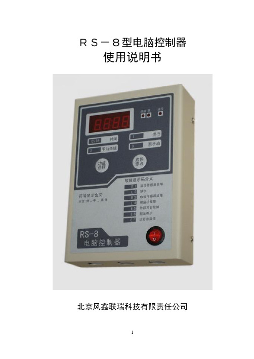
RS-8型电脑控制器使用说明书北京风鑫联瑞科技有限责任公司目录第一节概述………………………………………………………3电气性能……………………………………………………3第二节接线………………………………………………………4电气接线图…………………………………………………4第三节功能描述…………………………………………………5系统时间显示与修改……………………………………5运行功能(功能1,2,3)………………………………5功能1:连续运行或定时运行功能2:燃烧机手动控制功能3:泵手动控制控制运行的参数设置与修改(功能4-9-17)………6第四节运行控制说明………………………………………………8连续运行………………………………………………8定时运行………………………………………………8水泵控制输出说明………………………………………8第五节控制器诊断说明……………………………………………9RS-8型电脑板自检测试………………………………9附录安装尺寸图………………………………………………10机箱安装尺寸图……………………………………………10镶嵌式面板安装尺寸图……………………………………10第一节概述RS-8型电脑全自动锅炉控制器,核心采用日本富士通公司生产的单片机做为处理器,具有极高的可靠性和抗电磁干扰能力。
本控制器共有17项功能,适用于各种小型炉(烧开水、烧热水),结构简单、操作容易、性能稳定可靠、具有极高的性价比。
可以安装在各种外形规格(立式、卧式、圆柱形、方形)的炉体上。
电气性能运行方式:全自动连续运行工作方式:按预置参数运行。
定时运行方式:在4个时间段内按预置参数运行。
手动控制运行方式:手动控制燃烧器和水泵启停(用于测试、调试)。
基本功能:4位数码及指示灯显示控制状态、水泵状态、运行状态、当前水位;水温。
2个触摸操作按键;24小时计时的时钟电路,停电后电池对时钟电路继续供电3天以上;有停电记忆功能,来电后自动按停电前模式运行,适用于无人职守。
server2008r2standart 激活秘钥
server2008r2standart 激活秘钥1.引言概述部分的内容可以描述文章的背景和概要,向读者介绍文章所涉及的主题和目的。
同时,可以引发读者兴趣,激发阅读的动机。
以下是一个示例:引言1.1 概述在当今的信息时代,服务器作为重要的运算和存储设备,在各种领域起着至关重要的作用。
Microsoft的Server 2008 R2 Standart(服务器2008 R2标准版)是一款备受欢迎的服务器操作系统,被广泛应用于企业网络、数据中心、云平台等各种环境。
然而,为了充分利用Server 2008 R2 Standart的功能和性能,服务器的激活过程是必不可少的。
在本文中,我们将重点讨论Server 2008 R2 Standart的激活秘钥,以帮助读者了解如何有效激活和使用这一操作系统。
本文的结构如下:首先,我们将介绍Server 2008 R2 Standart的特点和功能,包括其在服务器领域的重要性。
接着,我们将详细讨论激活秘钥的概念和作用,以及有效获取和使用这些秘钥的方法。
最后,我们将总结并得出结论,为读者提供一些实用的建议和指导。
通过阅读本文,读者将能够全面了解Server 2008 R2 Standart的激活秘钥,并且学会如何合理、有效地激活和使用这个功能强大的服务器操作系统。
无论您是一名系统管理员、网络工程师,还是对服务器操作系统有兴趣的普通读者,本文将为您提供有益的信息和实用的指导,帮助您更好地应用和管理这款操作系统。
在接下来的章节中,我们将深入探讨Server 2008 R2 Standart和激活秘钥的相关知识,希望读者能够通过本文获得所需的信息和技巧。
让我们一同开始这次关于Server 2008 R2 Standart激活秘钥的旅程吧!1.2 文章结构文章结构部分的内容可以写成如下:文章结构:本文将分为引言、正文和结论三个部分来介绍Server 2008 R2 Standart激活秘钥的相关内容。
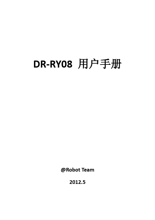
DR-RY08 用户手册
16
安装固定孔,共 2 个;左上、右下各 1 个;
2.2. 设置说明
模式更改
长按“SET”保持 2 秒,进入设置模式,短按“SET”键,将闪烁光标移动到模式位,按“+”、
“-”键,改变模式;
长按“SET”保持 2 秒,保存并退出设置;
不按任何键,30 秒后自动不保存退出;
显示
模式说明
0.92 1.92 2.08 3.a6 4.c3 5--
12
模块进入手动强切模式,慢速闪烁,每秒钟亮灭 1 次;
模块进入外部强切模式,快速闪烁,每秒钟亮灭 2 次;
13
复位按钮,处理器复位/重起;
外部强切;
14
接通 Override 两结点,则进入外部强切模式,继电器设置为预置的强切通断状
态,模块只受控于本地面板操作,所有总线操作无效;
15
导轨安装插锁,共 2 个;左下、右下各 1 个 ;
模块进入外部强切模式,快速闪烁,每秒钟亮灭 2 次;
8 通道状态指示与键盘输入;
8
LED 1~8 亮灭指示通道 1~8 通断状态;
按键 1~8 用于本地设置继电器通道 1~8 通断;
设置按键 “SET”、“+”、“-”
9
按住“SET”保持 2 秒,数码管闪烁,则进入设置模块,详细操作见后 2.2; 保存并退出:在设置状态下,长按“SET”2 秒则保存并退出;
ID 更改 长按“SET”保持 2 秒,进入设置模式,短按“SET”键,将闪烁光标移动到 ID 的高/低位, 按“+”、“-”键,改变 ID 值; 长按“SET”保持 2 秒,保存并退出设置; 不按任何键,30 秒后自动不保存退出;
波特率快捷更改(只适用于 2,3,4 模式) 长按“SET”保持 2 秒,进入设置模式,短按“SET”键 3 次,三位数码管同时闪烁当前波特 率数值,按“+”、“-”键,改变波特率值; 长按“SET”保持 2 秒,保存并退出设置; 不按任何键,30 秒后自动不保存退出;
BitDefender 综合安全版2008 使用指南

使用指南BitDefender综合安全版2008使用指南出版方2008.04.07版权©2008BitDefender法律须知版权所有。
在未得到来自BitDefender一方的书面授权,此手册的内容不得被复制或者通过任何方式传送给他人,无论是以电子或机械式,包括复印,记录,或者通过任何资料储存系统。
评论文章内所提到的简略引文有可能只是符合所提及的引文来源。
此手册内容不得以任何方式修改警告和否认声明.警告和否认声明。
此产品和所涉及的文档是受到版权保护。
此文件所提供的"基本"资讯是没有担保的。
“as is”虽然此文件是以谨慎的态度准备的,作者无须对任何人或有关方面的损失,或者因本文件内容而直接或间接性造成的伤害,做出负责。
此手册所包含的第三者网站连接是不在BitDefender控制之下,因此BitDefender无须对任何所连接网站的内容负责。
如果你从本文所提供的连接进入第三者网站,后果自负。
BitDefender之所以提供连接,完全是基于方便,本文所属的连接并不代表BitDefender赞同或者接受对第三者网站的内容做出负责。
商标.商标名字将会出现在此手册。
本文所有注册以及未注册商标都是单独属于它们个自所公认的拥有者。
She came to me one morning,one lonely Sunday morningHer long hair flowing in the mid-winter windI know not how she found me,for in darkness I was walking And destruction lay around me,from a fight I could not win目录授权与保证 (ix)前言 (xii)1.本书中所使用 (xii)1.1.字型 (xii)1.2.额外说明 (xii)2.本书的结构 (xiii)3.寻求意见 (xiii)安装步骤 (1)1.BitDefender互联网保安2008 (2)1.1.系统要求 (2)1.2.安装步骤 (3)1.3.初始安装向导 (5)1.3.1.步骤1-注册Bitdefender互联网安全2008 (5)1.3.2.步骤2/6:建立一个BitDefender帐户 (6)1.3.3.步骤3/6:学习实时病毒报告 (8)1.3.4.步骤4/6选择任务开始运行 (9)1.3.5.步骤5/6-等待任务完成 (10)1.3.6.步骤6/6-总结 (11)1.4.升级 (11)1.5.删除,修复BitDefender (12)集中管理 (14)2.开始 (15)2.1.Bitdefender系统图标 (16)2.2.扫描活动工具条 (17)2.3.Bitdefender手动扫描 (17)2.4.游戏模式 (18)2.4.1.使用游戏模式 (18)2.4.2.改变游戏模式热键 (19)3.安全状态 (20)3.1.安全状态按钮 (22)3.2.家长控制状态按钮 (23)3.3.tuneup状态按钮 (23)3.4.备份状态按钮 (24)4.快捷任务 (25)4.1.安全 (25)4.1.1.更新Bitdefender (25)4.1.2.扫描 (27)4.2.备份 (31)4.2.1.启动备份向导 (32)4.2.2.开始还原系统 (36)4.3.调整 (40)4.3.1.硬盘卷碎片整理 (41)4.3.2.寻找重复文件 (44)4.3.3.清洁网际网路档案 (48)4.3.4.删除档案永久 (51)4.3.5.清理登记 (54)4.3.6.回收清理登记 (58)5.历史 (61)6.注册 (63)6.1.步骤1/3-注册Bitdefender互联网安全2008 (63)6.2.步骤2/3:创建BitDefender帐户 (64)6.3.步骤3/3-注册Bitdefender互联网安全2008 (66)高级安全管理 (67)7.设置台 (68)7.1.配置一般设置 (69)7.1.1.一般设置 (70)7.1.2.病毒报告设置 (71)7.1.3.管理设置 (71)8.防毒 (72)8.1.按访问扫描 (72)8.1.1.配置防护级别 (73)8.1.2.定制防护级别 (74)8.1.3.禁用实时保护 (77)8.2.在需要时扫描 (78)8.2.1.扫描任务 (79)8.2.2.快捷菜单 (81)8.2.3.增加扫描任务 (82)8.2.4.设置扫描任务 (82)8.2.5.扫描对象 (92)8.2.6.浏览扫描日志 (99)8.3.部分不扫描 (101)8.3.1.拒绝扫描路经 (103)8.3.2.不包括扩展扫描 (105)8.4.隔离区 (108)8.4.1.管理隔离文件 (109)8.4.2.隔离区设置 (110)9.防火墙 (112)9.1.防火墙的见解 (112)9.1.1.什么是防火墙的好处? (112)9.1.2.什么是网络区 (113)9.1.3.防火墙操作 (114)9.2.防火墙状态 (115)9.2.1.配置防护级别 (117)9.3.流量控制 (117)9.3.1.自动添加规则 (118)9.3.2.人工添加规则 (119)9.3.3.添加规则 (124)9.3.4.修改文档 (124)9.3.5.修改文档 (126)9.4.高级设置 (127)9.4.1.配置ICMP过滤设置 (128)9.4.2.配置高级防火墙设置 (128)9.5.连接控制 (130)9.6.网络区 (131)9.6.1.添加区域 (133)10.反垃圾邮件 (135)10.1.反垃圾邮件见解 (135)10.1.1.防垃圾邮件过滤器 (135)10.1.2.反垃圾邮件设置 (137)10.2.反垃圾邮件状态 (139)10.2.1.步骤1-建立安全等级 (140)10.2.2.步骤2-填入地址名单 (141)10.3.反垃圾邮件设置 (144)10.3.1.反垃圾邮件设置 (145)10.3.2.基本反垃圾邮件过滤 (145)10.3.3.高级防垃圾邮件过滤器 (145)10.4.登录到邮件客户端 (146)10.4.1.反病毒工具栏 (146)10.4.2.反病毒配置对话框 (153)11.隐私控制 (160)11.1.隐私状态 (160)11.1.1.隐私控制 (161)11.1.2.反钓鱼保护 (162)11.2.高级设置身份识别控制 (163)11.2.1.创建身份识别规则 (164)11.2.2.定义例外 (167)11.2.3.添加规则 (168)11.3.高级设置-注册控制 (169)11.4.高级设置-曲奇控制 (171)11.4.1.配置向导 (173)11.5.高级设置-脚本控制 (175)11.5.1.配置向导 (176)11.6.系统信息 (177)11.7.反钓鱼工具栏 (179)12.家长监控 (181)12.1.保护父母控制设置 (181)12.2.家长监控状态 (182)12.2.1.选择保护控制 (183)12.2.2.配置启发式Web过滤 (184)12.3.网络监控 (184)12.3.1.配置向导 (185)12.3.2.具体例外 (187)12.3.3.BitDefender网页黑名单 (187)12.4.应用程序监控 (188)12.4.1.配置向导 (188)12.5.关键词过滤 (189)12.5.1.配置向导 (190)12.6.网络限时器 (192)13.更新 (194)13.1.自动更新 (194)13.1.1.要求更新 (196)13.1.2.禁用自动更新 (196)13.2.更新设置 (197)13.2.1.设置更新源 (197)13.2.2.配置自动更新 (198)13.2.3.配置手动更新 (199)13.2.4.配置高级设置 (199)13.2.5.修改文档委托书管理 (199)高级备份管理 (202)14.高级备份管理 (203)14.1.菜单栏 (203)14.2.Navigator Bar (205)14.2.1.起步 (206)14.2.2.管理工作 (207)14.2.3.日志查看 (230)14.2.4.工具箱 (233)BitDefender救援光盘 (235)15.概要 (236)15.1.系统要求 (236)15.2.含有的软件 (237)16.BitDefender救援光盘 (240)16.1.启动BitDefender救援光盘 (240)16.2.停止BitDefender救援光盘 (241)16.3.如何我才能进行反病毒扫描? (242)16.4.我怎么更新bitdefender代理? (243)16.5.我如何保存我的数据? (243)获得援助 (246)17.支持 (247)17.1.BitDefender基础知识 (247)17.2.请求帮助 (247)17.2.1.网上自助服务 (247)17.2.2.打开支持票 (248)17.3.联系信息 (248)17.3.1.有效网址 (248)17.3.2.分公司 (249)词汇 (252)授权与保证如果您不赞同这些条款和条件,请不要安装此软件。
Freescale 半导体用户指南:Proximity Sensing软件快速参考用户指南说明书

KITPROXIMITYEVM© Freescale Semiconductor, Inc., 2008. All rights reserved.PROXQRUG Rev 2, 05/2008Freescale Semiconductor User’s Guide Proximity Sensing Software Quick Reference User’s GuideDevices Supported: HCs08, RS08 and V1 MCUProximity Sensing SoftwareOverviewAny MCU can be enabled for touch sensing capabilities with a properly designed layout and a simple software module. This document explains how to use the Proximity Sensing Software in different MCU’s boards. This application can be used in conjunction with the Proximity daughter board PROXIMITYDBOARD0 for a complete evaluation set.NOTEThe Proximity Software is compatible with all S08, RS08 and V1 microcontrollers but hardware is necessary to test it. This document explains how to setup up the Proximity Software with a DEMO board and the PROXIMITYDBOARD0 board, which are included in the KITPROXIMITYEVM. The kit can be purchased at /proximity.System RequirementsThe requirements needed for the system are listed below.Proximity Software Requirements:•Freescale MCU (A demo board such as DEMOQE128 is recommended)•CodeWarrior 5.1 or later•Properly designed hardware for electrodes (PROXIMITYDBOARD0 recommended)Proximity GUI Requirements:•Freemaster 1.3 software for BDM connection. •.Net Framework 2.0•MCU loaded with the Proximity Software•BDM connection to MCU (included in most Demo boards, currently only P&E modules are supported)•Certified USB cable to avoid noise •15Mb of hard drive spacePROXQRUG SensorsApplication SetupOverviewThis section explains how to program your MCU and how to connect the MCU evaluation board with the PROXIMITYBOARD0 board to test the Software.NOTEThis application is configured by default for the DEMOQE128 board. Keep in mind the electrode pins can be configured by the user. The intention of this software is for the users to create their own applications.Hardware SetupBoard DescriptionThe next figure shows the board PROXIMITYDBOARD0. This board has three different electrode arrangements, a jumper, a pin header and a buzzer.NOTEThe three different electrode arrangements of the PROXIMITYDBOARD0 are connected in parallel. Electrode1 (E1) from the Key pad is connected to E1 from the Slider and E1 from the Rotary.Figure 1. PROXIMITYDBOARD0 Board 1. Buzzer 4. Key pad 2. Jumper5. Slider 3. 30 pin header6. RotaryPROXQRUGSensorsFigure 2 shows the possible connections depending of the jumper position.Figure 2. Jumper ConnectionsTable 1 shows the header pins that are connected to the electrodes in the PROXIMITYDBOARD0 board. For detailed information about connections, please refer to Appendix A of this document.CompatibilityThe PROXIMITYDBOARD0 board is only compatible with the following MCU boards.•DEMO9S08QG8•DEMO9S08QD4•DEMOQE128•DEMO9S08AW60•DEMO9S08DZ60•DEMO9S08LC60•DEMOJMSKT •DEMO9S08RG60Table 1. PROXIMITYDBOARD0 30 Pin HeaderSignal PinPin Signal Vcc 12NC GND 34NC NC 56NC NC 78Buzzer Electrode 1910NC Electrode 21112NC Electrode 31314NC Electrode 41516NC Electrode 51718NC Electrode 61920NC Electrode 72122NC Electrode 82324Buzzer NC 2526NC NC 2728NC NC2930NCPROXQRUG SensorsHow to Connect the PROXIMITYDBOARD0 with an MCU Demo Board1.Remove the jumpers that share functions in the Demo board. For example, in DEMOQE128 remove the jumpers associated to PTC0, PTC1 and PTB5 pins. For detailed information regarding jumper removal, see Appendix B .2.Find pin 1 in the male header of the PROXIMITYDBOARD0.3.Locate the female header slot number 1 in the supported Demo board as shown in Figure 3. The back side of the DEMOQE128 board is shown inFigure 4.Figure 3. MCU Port Socket HeaderPROXQRUGSensors4.Plug PROXIMITYDBOARD0 socket into the MCU port header. Remember that pins 1 and 3 from both headers must be connected. The two boards must look like the example below.Figure 4. The Two Boards Connected5.Connect the USB cable to your PC, and the other side of the cable to the DEMO board.6.The boards are connected as shown in Figure 5.Figure 5. System SetupFirmware SetupThis section explains how to program any supported Freescale MCU with the Proximity Software. Also described is how to change from one demo board to another one and how to configure the software for a custom application.How to Program the MCU1.It is necessary to have installed CodeWarrior 5.1 or later to program the required MCU. If it is not installed,please install it.2.You can find the Proximity project in: C:/Program Files/Freescale/Freescale Proximity SensingSoftware/proximity Source Code. There are two folders, just select the desired one.3.Open CodeWarrior and open the Proximity.mcp project file.4.Click on the Make button as shown in Figure 6Make button Debug buttonFigure 6. CodeWarrior Buttons5.Click on the Debug button.6.A new window appears, then click Connect and the debugger window will pop up. If this action fails, verify thehardware connections.PROXQRUGSensors7.In the debugger window click on the Run buttonRun buttonFigure 7. Run Button8.Now the microcontroller is running the Proximity Sensing Software.PROXQRUG SensorsPROXQRUG SensorsPower Demo BoardThe Proximity Software uses the MC9S08QE128 microcontroller by default. If the user wants to change the board, for example to the DEMO9S08DZ60, follow the next steps:1.Change the target in CodeWarrior as shown in the steps in the figure below.Figure 8. Changing the Targetpile the Proximity Project.3.Load the Proximity Software in the DZ60 microcontroller4.Plug the DEMO9S08DZ60 board with the PROXIMITYDBOARD0 board.5.The Demo board has been changed.PROXQRUGSensorsBuilding an ApplicationIf a user builds their own application and wants to use the Proximity Software as a guide, some considerations must be taken:•Change the required GPIOs (this will be explained further in the document). The pins used to connect the electrodes must be I/O.•Change the Timer interrupt vector number in the Timer.h file, as the timer overflow vector number is different in the S08 families.•Change the DD_OFFSET, within the GPIO.h file, as some MCUs have the data direction register in a different memory address.The next steps explain how to correctly use the pins that will be connected to the electrodes. 1.Open the GPIO.c file that contains all the MCU definitions.2.Search at the end of the file the line “User defined” (Figure 9). There are two definitions that might be used to write the pin number to be connected to the electrodes. vpPort1 is used to define the port pins that will be connected to the electrodes. vpPort2 is used to define the pin that will drive the buzzer. Remember that Proximity Software uses only eight electrodes, and if it is desired to change the number of electrodes, other steps will be necessary to do. Please refer to AN3579 for detailed information.Figure 9. GPIO.c File3.The next figure shows the GPIO.c file configured to work with the DEMOQE128 board and the PROXIMITYDBOARD0.Figure 10. GPIO.c File for DEMOQE128Table 2 shows the pins from the DEMOQE128 MCU port that will be connected to PROXIMITYDBOARD0 board and were previously configured in Figure 10.Table 2. DEMOQE128 MCU PortSignal Pin Pin SignalVDD12PTA5/RESETVSS34PTA5/RESETPTB156PTA4PTB078PTE7PTA2910VREFHPTA31112VREFLPTC01314PTA0PTC11516PTA1PTB31718PTF0PTB41920PTF1PTB22122PTA6PTB52324PTA7PTD12526PTH6PTD22728PTH7PTD02930PTD4PTD33132PTD5PTC23334PTD6PTC33536PTD7PTC43738PTC7PTC53940PTC6PTF23738PTB7PTF33940PTB6PTF43940PTG0PTF53738PTG1PTF63940PTH0PTF73940PTH1PTG23738NCPTG33940NCConclusionThis users guide explains the Proximity Sensing Software and the porting to different Freescale microcontroller platforms.The software is provided to speed up the design of new applications and to test the Proximity Sensing Technology.This document describes the required changes for the system to work properly. The example application demonstrates how to use the PROXIMITYDBOARD0 and the supported MCU tools. Any new design for a particular application with the required electrodes arrangement should consider this document and reference material below:•AN3579 - Enabling an MCU for Touch Sensing with Proximity Sensor SoftwarePROXQRUGSensorsPROXQRUGSensorsAppendix A: Electrode Configuration for Commonly Used Demo BoardsTable 3. Configuration Table for the Demo BoardsSignals Demo QE128Demo 9S08QG8Demo 9S08QD4Demo 9S08AW60Demo JM Demo 9S08RG60Demo 9S08LC60Demo 9S08DZ60Electrode 1PTA2PTA2PTA2PTG0PTG0PTC0PTC4PTG2Electrode 2PTA3PTA3PTA3PTG1PTG1PTC1PTC5PTG3Electrode 3PTC0PTA5(1)NOTES:1. This pin is the RESET pin. This pin must not be connected to an electrode, because it operates only as input.PTA5(2)2. This pin is the RESET pin. This pin must not be connected to an electrode, because it operates only as input.PTE2PTE2PTD6PTC2PTD2Electrode 4PTC1PTA0PTA0PTE3PTE3PTB7PTC3PTD3Electrode 5PTB3PTB3NC PTE6PTE5PTC4PTB5PTE4Electrode 6PTB4PTB4NC PTE5PTE4PTC5PTB4PTE5Electrode 7PTB2PTB2NC PTE7PTE6PTC6PTB6PTE3Electrode 8PTB5PTB5NC PTE4PTE7PTC7PTB7PTE2Time Vector Number 77711156711BuzzerPTE7/PTA7PTB7/NCPTB7/NCPTG4/PTB7NC/PTB7PTB2/PTA1NC/PTA7PTF7/PTB0Appendix B: Jumper Configurations for Demo BoardsThe following figures show the jumpers that need to be removed from the supported demo boards.PTB4, PTB5, PTB6, PTB7 PTC3, PTC4, PTC5PTC2Figure 11. DEMO9S08LC60 BoardPROXQRUGSensorsPTC0 andPTC1PTB5Figure 12. DEMOQE BoardPTE2 and PTE3Figure 13. DEMOJM BoardPROXQRUG SensorsRV1Figure 14. DEMO9S08QG8 BoardRV1Figure 15. DEMO9S08QD4 BoardPROXQRUGSensorsIn the following boards, the jumpers do not need to be removed.Jumper does not need to be removedFigure 16. DEMO9S08DZ60 BoardJumper does not need to be removedFigure 17. DEMO09S08AW60 BoardPROXQRUG SensorsAppendix C: Proximity PROXIMITYDBOARD0 Board SchematicsFigure 18. PROXIMITYDBOARD0 Board SchematicsPROXQRUGSensorsPROXQRUGSensorsFigure 19. PROXIMITYDBOARD0 Board Top ViewFigure 20. PROXIMITYDBOARD0 Board Bottom ViewPROXQRUG SensorsFigure 21. PROXIMITYDBOARD0 Board Top Etch ViewFigure 22. PROXIMITYDBOARD0 Board Bottom Etch ViewHow to Reach Us:Home Page:Web Support:/supportUSA/Europe or Locations Not Listed: Freescale Semiconductor, Inc. Technical Information Center, EL516 2100 East Elliot RoadTempe, Arizona 852841-800-521-6274 or +1-480-768-2130 /supportEurope, Middle East, and Africa:Freescale Halbleiter Deutschland GmbHTechnical Information CenterSchatzbogen 781829 Muenchen, Germany+44 1296 380 456 (English)+46 8 52200080 (English)+49 89 92103 559 (German)+33 1 69 35 48 48 (French)/supportJapan:Freescale Semiconductor Japan Ltd.HeadquartersARCO Tower 15F1-8-1, Shimo-Meguro, Meguro-ku,Tokyo 153-0064Japan0120 191014 or +81 3 5437 9125***************************Asia/Pacific:Freescale Semiconductor China Ltd.Exchange Building 23FNo. 118 Jianguo RoadChaoyang DistrictBeijing 100022China+86 010 5879 8000**************************For Literature Requests Only:Freescale Semiconductor Literature Distribution Center P.O. Box 5405Denver, Colorado 802171-800-441-2447 or +1-303-675-2140Fax: +1-303-675-2150*********************************************Information in this document is provided solely to enable system and software implementers to use Freescale Semiconductor products. There are no express or implied copyright licenses granted hereunder to design or fabricate any integrated circuits or integrated circuits based on the information in this document.Freescale Semiconductor reserves the right to make changes without further notice to any products herein. Freescale Semiconductor makes no warranty, representation or guarantee regarding the suitability of its products for any particular purpose, nor does Freescale Semiconductor assume any liability arising out of the application or use of any product or circuit, and specifically disclaims any and all liability, including without limitation consequential or incidental damages. “Typical” parameters that may be provided in Freescale Semiconductor data sheets and/or specifications can and do vary in different applications and actual performance may vary over time. All operating parameters, including “Typicals”, must be validated for each customer application by customer’s technical experts. Freescale Semiconductor does not convey any license under its patent rights nor the rights of others. Freescale Semiconductor products are not designed, intended, or authorized for use as components in systems intended for surgical implant into the body, or other applications intended to support or sustain life, or for any other application in which the failure of the Freescale Semiconductor product could create a situation where personal injury or death may occur. Should Buyer purchase or use Freescale Semiconductor products for any such unintended or unauthorized application, Buyer shall indemnify and hold Freescale Semiconductor and its officers, employees, subsidiaries, affiliates, and distributors harmless against all claims, costs, damages, and expenses, and reasonable attorney fees arising out of, directly or indirectly, any claim of personal injury or death associated with such unintended or unauthorized use, even if such claim alleges that Freescale Semiconductor was negligent regarding the design or manufacture of the part. Freescale™ and the Freescale logo are trademarks of Freescale Semiconductor, Inc. All other product or service names are the property of their respective owners.© Freescale Semiconductor, Inc., 2008. All rights reserved.PPROXQRUG Rev. 2KITPROXIMITYEVM。
RS08使用指南.zip
飞思卡尔半导体文件编号:AN3266应用笔记第 1版,5/2006RS08使用向导by: Vincent KoSystems Engineering Microcontroller DivisionRS08是飞思卡尔推出的超低成本 8位 MCU 内核,本文主要介绍 RS08平台。
第一部分为用户提供使用 RS08的基本信息,第二部分包括沿用技术和概念的应用示例。
RS08介绍本部分通过介绍 RS08架构、编程模式、指令集等来帮助用户了解 RS08平台;一般会以 MC9RS08KA2为基准,通过参考实例的方式来作介绍,有必要的话,也会提供飞思卡尔 HC08和 S08平台的交叉参考。
目录1 RS08介绍 (1)1.1 RS08架构............................................................2 1.2 RS08指令集........................................................6 1.3 内存分页结构......................................................15 1.4 MCU 复位...............................................................16 1.5 等待模式............................................................17 1.6 停止模式.............................................................17 1.7 子程序调用 (18)1.8 中断..................................................................19 2 模拟 ADC 应用实例 ........................................................22 2.1 执行.......................................................................22 2.2 校准...................................................................27 2.3 测量结果 .. (28)附录 A 程序实例 (30)This document contains information on a new product under development.Freescale reserves the right to change or discontinue this product without notice. ©Freescale Semiconductor, Inc., 2007. All rights reserved. General Business Information1.1 RS08架构RS08平台是专为超低成本的应用而设计。
RSEnergyMetrix软件版本1.8用户指南说明书
Release NotesRSEnergyMetrix Software Version 1.8Catalog Numbers 9703What’s New?RSEnergyMetrix software version 1.8 incorporates a number of changes in functionality, compatibility, and packaging.Package Contents The contents of the RSEnergyMetrix software product packaging have changedin several ways:•RSEnergyMetrix software now supports FactoryTalk Activation software. You will find the FactoryTalk Activation information envelope in theproduct package. EVRSI Master Disk activation diskettes are no longerprovided.•Only RSEnergyMetrix Manager software products include an installation CD. Options such as Real Time (RT), ReportsPlus, ChartsPlus, and 3PX(3rd Party OPC Client) are furnished with FactoryTalk Activationsoftware only. T o install these options, install their activations by usingFactoryTalk Activation Manager software.•The RSEnergyMetrix Software Getting Results Guide, publication ENEMTX-GR001, is provided on the installation CD as an AdobeAcrobat PDF file. A printed Getting Results Guide is no longer furnished.•RSEnergyMetrix Manager software products bundled with Microsoft SQL server are now supplied with Microsoft SQL Server 2005 SP3.Topic Page What’s New?1Package Contents 1Enhancements 2Corrected Anomalies 3Known Anomalies 4Additional Resources 42Enhancements The following product enhancements are part of RSEnergyMetrix softwareversion 1.8:Table 1 - Enhancements with Version 1.8Cat. No.Enhancement9703RSEnergyMetrix software now requires Microsoft .NET Framework 3.5 SP1 on the server.RSEnergyMetrix software now supports 64-bit Windows operating systems (RSLinx Classic software, version 2.57 CPR 9 SR 3 or later,required). The installation CD includes RSLinx Lite software, version 2.57 CPR 9 SR 3. The RSEnergyMetrix Getting Results Guide,publication ENEMTX-GR001, provides specific instructions on installing RSEnergyMetrix software on a Windows 2008 Server R2 64-bitoperating system.The installation CD includes FactoryTalk Activation Manager software, version 3.30.It is no longer necessary to stop Rockwell Automation software services before installing activations.A link to the RSEnergyMetrix software online Help is now provided on the installation menu.The Internet Explorer browser is no longer provided on the installation CD.The installation CD includes Adobe Acrobat Reader software, version 9.1.The installation CD includes Microsoft SQL Server 2005 Express Edition SP3, replacing MSDE 2000.The rich-client options Real Time (RT) and ChartsPlus now require .NET Framework 3.5 SP1 installed, and .NET Framework 2.0 zone security to be configured on each client computer.RSEnergyMetrix software supports data logging from the following:–Allen-Bradley MicroLogix programmable controllers on an EtherNet/IP network–Overload relay E3 Plus EC5 on a DeviceNet network–Overload relay E1 Plus on DeviceNet and EtherNet/IP networks–Motor protection product 825-P on a DeviceNet networkNavigation trees run in an on-demand fashion. Nodes are loaded only when expanded after you select them. This on-demand functionalitymay be enabled or disabled in the System Configuration page.Custom pages now support URL links in addition to uploaded files.WebLogger2 has been added to perform Web logging at a 15-minute interval. Added ‘delay’ parameter to the WebLogger2PIM.dll.configfile. WebLogger2 supports the standard alarming functionality.Alarming is now supported for OPC meter tags.Fiscal calendars may be configured and used for reporting, trending, and calendar trending.The display of calendar trends has been improved, adding previous and next month buttons, enhancing visibility of calendar date selectors, and permitting zoomed dates to be unselected.MarkerSize property was added to the Multi-purpose Report TrendChart object.3Corrected Anomalies The following product changes were included when the product shipped to you: Table 2 - Corrected Anomalies with Version 1.8Cat. No.Description9307RSLinx software, version 2.55 and later, no longer includes RsiOpcAuto.dll. Therefore, RSEnergyMetrix software now installs it.Exception occurred with the Overlay chart in ChartsPlus when the user changed the time zone and no pen had been selected.The Navigation tree threw an exception when a domain user that did not belong to a global role logged in when the domain had CustomPages assigned to it.The derived tag functions TagTotal, TagSum, and TagAverage now return Nothing instead of zero when there is no tag data.You could not install RSEM if .NET Framework 4 was installed. The workaround was to temporarily uninstall .NET Framework 4.A meter could not be edited when the meter count limit had been reached.Removed the SQL Server dependency for the RSEnergyMetrix Logger service. A server might experience continuous reboots if an SQL Serverdefault instance is not installed on the RSEnergyMetrix server.Weekly auto-run reports scheduled on Sunday would not execute more than once after a logger restart.Added the LRJ (List Report Jobs) command to the Telnet debugger.Added a note to the Alarm Subscription Setup page saying that at least one notification period must be defined in order for the user toreceive alarm emails.Changed the message that appears on the login page when no RSEnergyMetrix Manager activation is found. The old message was‘Maximum number of users has been reached. Please try again later’. The new message is ‘No RSEnergyMetrix Manager activation wasfound. Cannot log in’.The Enable comm loss alarm checkbox on the Device Setup page is now functional. An email is sent to alarm subscribers whencommunication loss with a device is detected, and another is sent when communication with the device is restored. The device must besuccessfully communicating after the logger service starts before the loss email can be triggered. This prevents nuisance emails when thelogger service starts. These communication alarms are not shown on the Alarm Status or the Alarm Log web pages.Added the following time zones to the TimeZoneIndexes.txt file: Bangladesh Standard Time, Syria Standard Time, Ulaanbaatar StandardTime, UTC+12, UTC-02, UTC-11.Corrected the Value Type for PM1000 EM2 Apparent Energy tags.Powermonitor 3000, Powermonitor II, RSEnergyMetrix, RSLinx, RSLinx Classic, FactoryTalk Activation, MicroLogix,Allen-Bradley, Rockwell Software, and Rockwell Automation are trademarks of Rockwell Automation, Inc.Trademarks not belonging to Rockwell Automation are property of their respective companies.Rockwell Otomasyon Ticaret A.Ş., Kar Plaza İş Merkezi E Blok Kat:6 34752 İçerenköy, İstanbul, T el: +90 (216) 5698400Publication ENEMTX-RN001A-EN-P - January 2011PN-100402Copyright © 2011 Rockwell Automation, Inc. All rights reserved. Printed in the U.S.A.Known Anomalies The following are the known anomalies for RSEnergyMetrix software version1.8:Additional Resources These documents contain additional information concerning related RockwellAutomation products.You can view or download publications at /literature/. T o order paper copies oftechnical documentation, contact your local Rockwell Automation distributor orsales representative.Table 3 - Known Anomalies with Version 1.8Cat. No.Description 9703RT Device configuration dialog box for the Powermonitor 3000 unit may need to be closed and reopened following an initial upload to enable all the model-related features in the dialog box.You must manually add the IP address of each Ethernet device to the RSLinx Classic Ethernet Devices driver on the RSEnergyMetrix server.When RSLinx Classic software runs as a Windows service on the Windows 2008 Server, its user interface is not available. The RSLinx Classic user interface is available only when RSLinx Classic software runs as an application.After configuring EtherNet/IP devices in RSLinx software, it may be necessary to open RSWho and then navigate to and select each device, including Logix processor modules, to enable RSEnergyMetrix software to connect to the devices.The rich-client options RT (Real Time) and ChartsPlus will not run on the server if installed on a supported 64-bit operating system. The RT and ChartsPlus options will run on client computers running a supported 32-bit Windows operating system.Internet Explorer WebControls must be installed after IIS is installed and running. If IIS is installed after these components, then you must reinstall those components.RSEnergyMetrix RT (Real Time) does not support DeviceNet communication to the Powermonitor II unit.If RSEnergyMetrix software is installed with a connection to an SQL server on another machine, MSDE or SQL Server 2005 Express Edition must be installed on the RSEnergyMetrix server.Scheduling many auto-run reports to run at the same time may cause excessive server resource demand and cause reports to time out.Reports that run automatically in Microsoft Excel format may not be viewed in the Web browser if the client has the Microsoft Office 97 suite installed. The report may still be saved and opened by using Microsoft Excel software.ResourceDescription RSEnergyMetrix Software Version 1.8 Getting Results Guide, publication ENEMTX-GR001Provides information for using RSEnergyMetrix software.Product Certifications website, Provides declarations of conformity, certificates, and other certification details.。
SuperWorks8.0使用手册

目录1. 第一章环境设置 (7)1.1 1-1 绘图环境初始化 (7)1.2 1-2 系统设置 (7)1.3 1-3 设置图幅 (12)1.4 1-4 图幅替换 (14)1.5 1-5 标题栏填写 (14)1.6 1-6 标题栏库管理 (15)1.7 1-7 插入标题栏 (17)1.8 1-8 标题栏替换 (18)1.9 1-9 标题栏批替换 (18)1.10 1-10 动态提示打开/关闭 (20)1.11 1-11 文件任务栏隐藏显示 (20)1.12 1-12 项目/设备显示 (20)2. 第二章项目与设备 (21)2.1 2-1 项目/设备新建并打开 (21)2.2 2-2 项目/设备打开 (22)2.3 2-3 项目/设备关闭 (23)2.4 2-4 文件保存到项目/设备 (23)2.5 2-5 项目/设备管理 (24)2.6 2-6 项目清册 (25)2.7 2-7 文件类型扩充 (26)2.8 2-8 图纸批处理及目录生成 (27)2.9 2-9 图纸批打印 (29)2.10 2-10 图纸比对 (32)2.11 2-11 元件状态记录 (33)2.12 2-12 元件历史查询 (34)3. 第三章二次原理设计 (36)3.1 3-1 原理图设计 (36)3.1.1 3-1-1 图纸属性定义 (36)3.1.2 3-1-2 围框定义元件安装位置 (37)3.1.3 3-1-3 链式画法 (39)3.1.4 3-1-4 回路线框调用画法 (42)3.1.5 3-1-5 点式画法 (47)3.1.6 3-1-6 转换开关设计 (49)3.1.7 3-1-7 多线绘制 (52)3.1.8 3-1-8 典型图库调用 (55)3.1.9 3-1-9 PLC元器件数据库 (58)3.1.10 3-1-10 PLC元器件绘制 (61)3.1.11 3-1-11 属性编辑 (64)3.1.12 3-1-12 符号属性刷 (67)3.1.13 3-1-13 组合元件 (68)3.1.14 3-1-14 线号编辑 (70)3.1.15 3-1-15 标号批标注 (71)3.1.16 3-1-16 线号批标注 (72)3.1.17 3-1-17 端号批标注 (73)3.1.18 3-1-18 端子信息批描述 (75)3.1.19 3-1-19 屏面布置图调用 (76)3.1.20 3-1-20 屏端子统计及端子条绘制 (77)3.2 3-2 原理图编辑修改 (79)3.2.1 3-2-1 符号反向 (79).2 3-2-2 符号复制 (80)3.2.3 3-2-3 符号替换 (80)3.2.4 3-2-4 符号移动 (82)3.2.5 3-2-5 符号删除 (82)3.2.6 3-2-6 字符替换 (83)3.2.7 3-2-7 电路复制与粘贴 (85)3.2.8 3-2-8 单根线引脚属性定义 (86)3.2.9 3-2-9 元件类型定义 (86)3.3 3-3 查图及联动修改 (87)3.3.1 3-3-1 元件查询及修改 (87)3.3.2 3-3-2 线号查询及修改 (89)3.3.3 3-3-3 文字查询及修改 (90)3.3.4 3-3-4 电路图检查 (93)3.3.5 3-3-5 文字链接定义 (96)3.3.6 3-3-6 文字链接编辑 (97)3.3.7 3-3-7 实体链接定义 (98)3.3.8 3-3-8 链接打开 (100)4. 第四章二次接线 (101)4.1 4-1 网络表生成 (101)4.2 4-2 明细表生成 (102)4.3 4-3 元件分板 (110)4.4 4-4 端子表生成 (115)4.5 4-5 元件布置 (130)4.6 4-6 接线路径调整 (137)4.7 4-7 接线生成 (138)4.8 4-8 接线查看 (142)4.9 4-9 接线删除 (143)4.10 4-10 接线图元件逻辑关系查看 (144)4.11 4-11 连片集中布置 (145)4.12 4-12 小母线排 (146)4.13 4-13 出接线表 (147)4.14 4-14 生产规范书 (148)4.15 4-15 一二次元件明细汇总 (150)4.16 4-16 一键更新 (152)5. 第五章库管理维护 (154)5.1 5-1 库管理 (154)5.1.1 5-1-1 符号建库 (155)5.1.2 5-1-2 符号分类 (159)5.1.3 5-1-3 等价符号 (159)5.1.4 5-1-4 多端元件库管理 (161)5.1.5 5-1-6 接线图章库管理 (166)5.1.6 5-1-7 数据库管理 (179)5.1.7 5-1-8 库备份 (183)6. 第六章接线图章布置手动接线工具箱 (185)6.1 6-1 接线图章布置工具箱 (185)6.1.1 6-1-1 接线图章工具箱 (185)6.1.2 6-1-2 手动明细 (186)6.1.3 6-1-3 自动布置 (191)6.1.4 6-1-4 手动布置 (191)6.1.5 6-1-5 安装位置修改 (193)6.1.6 6-1-6 序号修改 (193)6.1.7 6-1-7 标号修改 (194)6.1.8 6-1-8 明细修改 (194)6.1.9 6-1-9 接线图元件修改及查看 (195)6.1.10 6-1-10 图章替换 (198)6.1.11 6-1-11 图面调整 (199)6.1.12 6-1-12 统计明细 (200)6.2 6-2 手动接线工具箱 (201)6.2.1 6-2-1 手动接线工具箱 (201)6.2.2 6-2-2 手动接线 (202)6.2.3 6-2-3 点点接线 (212)6.2.4 6-2-4 接线移动 (213)6.2.5 6-2-5 双向接线删除 (214)6.2.6 6-2-6 整组接线删除 (214)6.2.7 6-2-7 全部接线删除 (214)6.2.8 6-2-8 接线查看 (214)6.2.9 6-2-9 接线重新生成 (216)6.2.10 6-2-10 接线端子表重新生成 (216)6.2.11 6-2-11 出接线表 (217)7. 第七章一次设计 (219)7.1 7-1 一次系统图生成 (219)7.1.1 7-1-1 一次系统图模板设置 (219)7.1.2 7-1-2 一次系统图图框绘制 (221)7.1.3 7-1-3 一次系统图图框更新 (221)7.1.4 7-1-4 母线绘制 (222)7.1.5 7-1-5 母线编辑 (222)7.1.6 7-1-6 一次方案调用 (223)7.1.7 7-1-7 一次方案属性编辑 (224)7.1.8 7-1-8 一次方案块明细编辑 (226)7.1.9 7-1-9 一次方案块替换 (227)7.1.10 7-1-10 一次方案查询修改及明细输出 (227)7.1.11 7-1-11 一次系统图填充 (229)7.1.12 7-1-12 一次方案建库 (230)7.1.13 7-1-13 一次系统图编辑器 (232)7.2 7-2 一次原理设计 (234)7.2.1 7-2-1 一次元件标注设置 (234)7.2.2 7-2-2 一次符号调用 (235)7.2.3 7-2-3 一次组合元件 (236)7.2.4 7-2-4 属性编辑 (237)7.2.5 7-2-5 一次元件明细表 (237)7.3 7-3 一次符号与一次元件库管理 (238)7.3.1 7-3-1 一次符号建库 (238)7.3.2 7-3-2 一次符号分类 (239)7.3.3 7-3-3 一次元件数据库 (240)8. 第八章面板开孔设计 (241)8.1 8-1 面板绘制 (242)8.2 8-2 面板编辑 (242)8.3 8-3 元件开孔图自动布置 (243)8.4 8-4 元件开孔图手动布置 (246)8.5 8-5 开孔图库管理 (247)9. 第九章辅助功能 (250)9.1 9-1 制表 (250)9.2 9-2 增加单元格 (251)9.3 9-3 词组调用 (252)9.4 9-4 明细表编辑器 (253)9.5 9-5 文字属性编辑 (255)9.6 9-6 文字对齐 (256)9.7 9-7 文字字符串替换 (257)9.8 9-8 直线转多义线 (257)9.9 9-9 线宽变换 (257)9.10 9-10 线型变换 (257)9.11 9-11 层变换 (258)9.12 9-12 层删除 (259)9.13 9-13 显示隐藏实体 (259)10. 第十章端子电缆工具箱 (260)10.1 10-1 端子表工具箱 (260)10.1.1 10-1-1 端子表工具箱 (260)10.1.2 10-1-2 端子表定义 (261)10.1.3 10-1-3 空端子表绘制 (265)10.1.4 10-1-4 端子表填写 (267)10.1.5 10-1-5 端子表批填写 (268)10.1.6 10-1-6 联络端子 (269)10.1.7 10-1-7 电流端子粗线绘制 (270)10.1.8 10-1-8 端子引线 (271)10.1.9 10-1-9 端子插入 (272)10.1.10 10-1-10 端子删除 (272)10.1.11 10-1-11 端子表安装位置定义 (272)10.1.12 10-1-12 端子表文字分类 (274)10.1.13 10-1-13 端子表分割 (275)10.1.14 10-1-14 端子表分割插入 (276)10.1.15 10-1-15 原理图端子表定义 (277)10.1.16 10-1-16 接线图端子表定义 (277)10.2 10-2 电缆工具箱 (278)10.2.1 10-2-1 电缆工具箱 (278)10.2.2 10-2-2 端子表电缆自动生成 (278)10.2.3 10-2-3 电缆绘制 (279)10.2.4 10-2-4 电缆插入 (280)10.2.5 10-2-5 电缆删除 (281)10.2.6 10-2-6 电缆参数定义 (281)10.2.7 10-2-7 电缆安装单位批定义 (283)10.2.8 10-2-8 电缆编号批定义 (284)10.2.9 10-2-9 电缆连线 (285)10.2.10 10-2-10 电缆连线调整参数设置 (292)10.2.11 10-2-11 电缆连线调整 (292)10.2.12 10-2-12 电缆查询 (293)10.2.13 10-2-13 电缆统计 (294)10.2.14 10-2-14 端子表电缆标注设置 (295)10.2.15 10-2-15 电缆参数字库扩充 (296)11. 附录AutoCAD系统预备知识 (298)11..1 一、基本编辑命令 (298)11..2 二、辅助绘图命令 (299)11..3 三、坐标系统及用户坐标 (302)11..4 四、基本屏幕操作命令 (304)11..5 五、基本编辑命令 (305)11..6 六、块操作 (309)11..7 七、层、颜色及线型 (311)11..8 八、简化命令制作 (312)1. 第一章环境设置主要功能:使未在模板文*下进行绘制的图形,恢复到绘图环*下(注:中定义了SuperWORKS正常运行所需的基本环境及参数)。
RS指令讲解之欧阳地创编
三菱FX2N PLC串行通讯指令(FNC 80 RS)串行通讯指令(FNC 80 RS)1、指令格式: [RS D0 K8 D10 K8]发送数据帧起始地址和数目↓接收数据帧起始地址和数目2、功能和动作:※ RS指令是为使用RS232C、RS485功能扩展板及特殊适配器,进行发送和接收串行数据的指令。
※ 传送的数据格式在后面讲述的特殊寄存器D8120设定。
RS指令驱动时即使改变D8120的设定,实际上也不接收。
※ 在只发送的系统中,可将接收数设定为K0。
(K表示常数)※ 在只接收的系统中,可将发送数设定为K0。
※ 在程序中可以多次使用RS指令,但在同一时间必须保证只有一个RS指令被驱动。
※ 在一次完整的通讯过程中,RS指令必须保持一直有效,直至接收数据完成。
D8120说明:※ 根据MD320的通讯协议,无帧头和帧尾,则(bit9,bit8)=(0,0)。
※ bit13~15是计算机链接通讯时的设定项目,使用RS 指令时必须设定为0。
※ RS485未考虑设置控制线的方法,使用FX2N485BD、FX0N485ADP时,(bit11,bit10 )=(1,1)。
※ 若PLC和变频器之间的通讯参数如下:8位数据位,无校验,2位停止位,波特率9600,无帧头无帧尾,无协议模式,则D8120=H0C89(H表示16进制)(0000 1100 1000 1001B)M8002│──||────────── [ MOV H0C89 D8120 ] 5、相关标志位:※ M8122:数据发送请求标志当PLC处于接收完成状态或接收等待状态时,用脉冲触发M8122,将使得从D0开始的连续8个数据被发送。
当发送完成后,M8122自动被复位。
当RS指令的驱动输入X0变为ON状态时,PLC就进入接收等待状态。
※ M8123:数据接收完成标志当M8123置位时,表明接收已经完成,此时需要将接收到的数据从接受缓冲区转移到用户指定的数据区,然后手工复位M8123。
RB08机器人使用说明书(20123月第2版)-2012-03-16定稿

急停键位于控制柜前门及示教盒的右上侧。
V
RB08 机器人 使用说明书
注意
z 进行机器人示教作业前要检查以下事项,有异常则应及时修理或采取其他必 要措施: 机器人动作有无异常; 外部电线遮盖物及外包装有无破损。
安全注意事项
使用前(安装、运转、保养、检修等),请务必熟读并全部掌握本使用说明书和 其他随行文件资料。在熟知全部设备知识、安全及注意事项后才能开始使用。
本使用说明书中的安全事项分为“危险”、“注意”、“强制”、“禁止”四类,将分 别叙述。
危险 误操作时有危险,可能发生死亡或重伤事故
注意
误操作时有危险,可能发生中等程度伤害或轻伤事故
在本产品使用说明书中,我们将尽力叙述各种与该产品使用相关 的事项。限于篇幅限制及产品具体使用等原因,不可能对产品中所有不 必做和/或不能做的操作进行详细的叙述。因此,本产品使用说明书中没 有特别指明的事项均视为“不可能”或“不允许”进行的操作。
本产品使用说明书的版权,归广州数控设备有限公司所有,任何 单位与个人进行出版或复印均属于非法行为,广州数控设备有限公司将 保留追究其法律责任的权利。
强制 必须严格遵守的事项
禁止 禁止的事项
另外,即使是“注意”所记载的内容,也会因情况不同而产生严重后果,因此任 何一条注意事项险”的内容,但为了确保安全和有效的操作, 用户也必须遵守的事项,将会在相关处加以叙述
III
RB08 机器人 使用说明书
第五章 保养、检修 ·································································································17
- 1、下载文档前请自行甄别文档内容的完整性,平台不提供额外的编辑、内容补充、找答案等附加服务。
- 2、"仅部分预览"的文档,不可在线预览部分如存在完整性等问题,可反馈申请退款(可完整预览的文档不适用该条件!)。
- 3、如文档侵犯您的权益,请联系客服反馈,我们会尽快为您处理(人工客服工作时间:9:00-18:30)。
飞思卡尔半导体文件编号:AN3266应用笔记第 1版,5/2006RS08使用向导by: Vincent KoSystems Engineering Microcontroller DivisionRS08是飞思卡尔推出的超低成本 8位 MCU 内核,本文主要介绍 RS08平台。
第一部分为用户提供使用 RS08的基本信息,第二部分包括沿用技术和概念的应用示例。
RS08介绍本部分通过介绍 RS08架构、编程模式、指令集等来帮助用户了解 RS08平台;一般会以 MC9RS08KA2为基准,通过参考实例的方式来作介绍,有必要的话,也会提供飞思卡尔 HC08和 S08平台的交叉参考。
目录1 RS08介绍 (1)1.1 RS08架构............................................................2 1.2 RS08指令集........................................................6 1.3 内存分页结构......................................................15 1.4 MCU 复位...............................................................16 1.5 等待模式............................................................17 1.6 停止模式.............................................................17 1.7 子程序调用 (18)1.8 中断..................................................................19 2 模拟 ADC 应用实例 ........................................................22 2.1 执行.......................................................................22 2.2 校准...................................................................27 2.3 测量结果 .. (28)附录 A 程序实例 (30)This document contains information on a new product under development.Freescale reserves the right to change or discontinue this product without notice. ©Freescale Semiconductor, Inc., 2007. All rights reserved. General Business Information1.1 RS08架构RS08平台是专为超低成本的应用而设计。
由于硬件部分设计的优化导致整个系统成本降低; RS08的管芯可以放在较小的封装中,譬如 6针双列平面无引脚(Dual Flat No lead :DFN )封装。
RS08平台保留与流行的 HC08/S08平台相似的编程模式可以轻易实现平台间程序源代码的移植。
RS08平台的主要特点有: ⍓指令集为 S08的子指令集;⍓映像程序计数器(Shadow Program Counter :SPC )的新指令:SHA 和 SLA ; ⍓为代码长度优化设计的新的微短寻址模式; ⍓最大 16K 的可寻址存储空间;⍓取消了中断和复位服务中的向量提取机制; ⍓取消了子程序调用中的 RAM 堆栈机制; ⍓子程序调用提供单层硬件堆栈;⍓通过执行 STOP 和 WAIT 指令提供低功耗模式的支持; ⍓通过内部或外部中断触发实现 Stop 状态的唤醒; ⍓提供非法寻址和操作码检测复位;⍓硬件加密实现对非遗失性的存储空间(NVM )非法访问的保护; ⍓用单线接口实现调试和非遗失性存储器的编程/擦除1.1.1 CPU 寄存器RS08的 CPU 寄存器包括一个 8位通用累加器( A ),一个 14位的程序计数器( PC ),一个 14位的映像程序计数器(SPC )和一个 2位的状态码寄存器(CCR )。
CCR 包含 2个状态标志,提供给像 BCS 和 BEQ 等条件跳转指令来使用。
图 1-1为 RS08 CPU 寄存器。
图 1-1. RS08 CPU 寄存器RS08使用指导,第 1版8位通用累加器A是RS08 CPU的基本数据寄存器。
利用LDA指令可以将数据从存储器中读到A中,利用STA指令可以将数据从A中写入存储器中。
新增加的2条指令SHA和SLA可以分别完成累加器A与映像程序计数器(SPC)的高8位和低8位的数据交换。
程序计数器(PC)中存放下一条指令的地址或操作数,由于RS08的程序计数器长度为14位,意味着RS08的最大寻址空间为16K字节。
在HC08/S08中,在使用JSR和BSR指令调用子程序时,PC返回值以堆栈方式放在RAM中;在RS08中,由于没有RAM堆栈机制,所以返回的地址保存在SPC寄存器中,在完成子程序调用后,RTS指令会从SPC 中恢复PC的值。
SPC只能保存单层的地址,所以嵌套的子程序调用必须利用软件堆栈来完成。
用户程序可以先利用SHA和SLA指令来分别完成A与SPC的高字节和低字节的内容交换,然后堆栈在RAM中。
状态寄存器(CCR)的状态位(Z和C)反应前一数学运算或其他运算的结果。
位的定义与HC08/S08中的定义相同,详细定义信息请参考RS08内核参考手册。
1.1.2 特殊寄存器除了CPU寄存器,还有两个内存映射寄存器与内核地址产生紧密相关;这就是间接数据寄存器(D[X])和索引寄存器(X),它们的地址分别位于$000E和$000F。
如图2所示。
寄存器D[X]和X共同实现间接数据寻址;读取寄存器D[X]时,X寄存器内容为对应寄存器的地址。
图1-3说明了间接寻址方案。
X和D[X]寄存器不是CPU内部寄存器,但是它们与RS08通用指令集的无缝集成形成了伪指令集。
1.1.3 通用寻址模式每当MCU从存储器读/写数据时,都会使用一种寻址模式来判断数据的实际地址。
表1-1总结了RS08平台支持的通用寻址模式。
GeneralBusinessInformation飞思卡尔半导体1.1.3.1 与HC08/S08 通用的寻址模式固定寻址、直接寻址、相对寻址、立即数寻址和扩展寻址等寻址模式在RS08中的操作与在HC08/S08中的操作相同。
固定寻址模式用在当CPU已经知道要完成指令的所有的信息并且在源代码中不提供任何的寻址信息。
相对寻址模式用于跳转指令中明确指定相对于程序计数器的地址偏移量。
立即数寻址用于当在一条指令中给出具体数值,这个值位于该指令操作码后面。
直接寻址模式用于访问在直接地址空间(从$0000到$00FF)的操作数。
扩展寻址模式用于中含有2字节操作数的指令,这种模式仅用于JMP和JSR指令中,指令中在操作数中给出14位的目标地址。
1.1.3.2 微短寻址模式RS08平台中引入微短寻址模式,该寻址模式与直接寻址模式具有相似的操作,但是寻址空间受到限制,只有直接寻址的可访问空间(在$0000 - $00FF范围内)的部分空间能够被微短寻址模式访问到。
当然,与这些寻址模式相关的所有指令都是单字节指令,最大限度的使用这些指令可以减少整个的代码长度。
微寻址模式适用于地址影像中前16字节空间的寻址,从$0000到$000F,对应的指令有加1(INC)指令、减1(DEC)指令,加(ADD)指令以及减(SUB)指令。
直接寻址模式中有同样功能的2字节指令,寻址空间从$0000到$00FF。
用户在源程序中在操作数之前加上小于号(<),可以强迫汇编编译器使用微寻址指令。
INC <$0DDEC <$0DADD <$0DSUB <$0D短寻址模式用于访问前32字节的空间,从$0000到$001F,适用于清除(CLR)指令,加载累加器A(LDA)指令和存储累加器A(STA)指令。
用户在源程序中在操作数之前加上小于号(<),可以强迫汇编编译器使用短寻址指令。
CLR<$1FLDA <$1FSTA <$1F1.1.3.3 伪寻址模式在使用特殊寄存器D[X]和X时,RS08通用指令集可以被用来模拟HC08/S08架构中的累加器X的操作。
这种模拟由汇编程序/编译器支持,在编译过程中完成。
当需要零偏移索引指令或与寄存器X相关的指令时,用户可以在RS08程序中使用与HC08/S08相同的编辑语法。
在编译中汇编程序会转换RS08伪指令为等同的通用RS08指令,这个操作对用户是透明的。
下面总结由RS08架构支持的伪寻址模式:❿伪固定寻址-例如:TSTX,DBNZX等伪固定寻址是利用等同的直接寻址模式模拟,操作数通过X寄存器(位置:$000F)加载。
有的操作,像DECX和INCX,可利用微短寻址模式指令,则伪指令变为单字节指令。
❿伪直接寻址-例如:LDX $20,STX $20是通过直接-直接移动(MOV)操作来模拟的。
LDX操作等同于移动操作数到X寄存器($000F);STX操作把X寄存器($000F)中的内容到操作数的目标地址。
❿伪立即数寻址-例如:LDX #$09是通过立即数-直接移动(MOV)操作来模拟的。
X寄存器直接加载指定的数据。
❿伪零偏移索引寻址-例如:ADD ,X是通过操作数总是从D[X]寄存器加载的直接寻址操作来模拟。
D[X]寄存器保存的间接数据的地址在X寄存器中;从而在D[X]寄存器上的操作等同于HC08/S08中的零偏移索引寻址。
RS08平台中保留相同与HC08/S08风格的译码语法,这样可以帮助用户方便的在这些平台之间移植源代码。
下面是一些代码例子:LDA ,XADD ,XDBNZ ,X,rel注意伪指令基于模拟完成的,都有等同的HC08/S08操作;然而,在CPU的时钟周期计数和指令字节数计数上是不同的。
在从HC08/S08平台向RS08平台移植源代码的时候要特别注意定时要求严格的软件。
1.2 RS08 指令集RS08的CPU内核可以认为是简化版的S08内核。
为保持源代码的兼容性,在RS08架构中保留了大部分的算术指令,但去除了用于复杂运算的一些指令:半位元交换(NSA)、乘(MUL)和除(DIV)。
