STM32F756IGT6各内置外设引脚分布
STM F 引脚功能定义

2.1 器件一览表二:器件功能和配置(STM32F103xx增强型)图一.STM32F103xx增强型模块框图工作温度=-40至+105°C (结温达125°C) AF: I/O口上的其他功能3管脚定义图二.STM32F103xx增强型VFQFPN36管脚图四.STM32F103xx增强型LQFP64管脚表三. 管脚定义表三.管脚定义(续)注:1. I :输入, O:输出, S:电源, HiZ:高阻2. FT:兼容5V3. 其中部分功能仅在部分型号芯片中支持,具体信息请参考表2。
4. PC13,PC14和PC15引脚通过电源开关进行供电,因此这三个引脚作为输出引脚时有以下限制:9作为输出脚时只能工作在2MHz模式下9最大驱动负载为30pF9同一时间,三个引脚中只有一个引脚能作为输出引脚。
5. 仅在内嵌大等于64K Flash的型号中支持此类功能。
6. VFQFPN36封装的2号,3号引脚和LQFP48,LQFP64封装的5号,6号引脚在芯片复位后默认配置为OSC_IN和OSC_OUT功能脚。
软件可以重新设置这两个引脚为PD0和PD1功能脚。
但对于LQFP100封装,由于PD0和PD1为固有的功能脚,因此没有必要再由软件进行设置。
更多详细信息请参考STM32F10xxx参考手册的复用功能I/O章节和调试设置章节。
PD0和PD1作为输出引脚只能工作在50MHz模式下。
7. 此类复用功能能够由软件配置到其他引脚上,详细信息请参考STM32F10xxx参考手册的复用功能I/O章节和调试设置章节。
4存储器映像图七存储器图5电气特性请参考英文版数据手册6封装参数请参考英文版数据手册7订货代码表四. 订货代码型号闪存存储器K字节SRAM存储器K字节封装STM32F103C6T6 32 10STM32F103C8T6 64 20STM32F103CBT6 128 20LQFP48STM32F103R6T6 32 10STM32F103R8T6 64 20STM32F103RBT6 128 20LQFP64STM32F103V8T6 64 20STM32F103VBT6 128 20LQFP100STM32F103V8H6 64 20STM32F103VBH6 128 20LFBGA100STM32F103T6U6 32 6STM32F103T8U6 64 10VFQFPN367.1 后续的产品系列后续的STM32F103xx增强型系列产品将会有更广泛的型号选择,芯片将会有更大的封装尺寸并内嵌多达512KB的Flash和48KB的SRAM。
STM32F100V8T6, STM32F100VBT6 引脚功能定义

Pin 19
VSSA
VSSA
Power - -230 70 180 Degrees
Pin 20
VREF-
VREF-
Power - -230 60 180 Degrees
Pin 21 VREF+
VREF+
Power - -230 50 180 Degrees
Pin 22
VDDA
VDDA
Power - -230 40 180 Degrees
TS PB14/SPI2_MISO/TIM1_CH2N/USART3_R
TS/TIM15_CH1 PB15/SPI2_MOSI/TIM1_CH3N/TIM15_CH
1N/TIM15_CH2 PD8/USART3_TX PD9/USART3_RX PD10/USART3_CK PD11/USART3_CTS PD12/TIM4_CH1/USART3_RTS PD13/TIM4_CH2 PD14/TIM4_CH3 PD15/TIM4_CH4 PC6/TIM3_CH1 PC7/TIM3_CH2 PC8/TIM3_CH3 PC9/TIM3_CH4 PA8/USART1_CK/MCO/TIM1_CH1 PA9/USART1_TX/TIM1_CH2/TIM15_BKI
Pin 2
PE3
PE3/TRACED0
I/O FT -230 240 180 Degrees
Pin 3
PE4
PE4/TRACED1
I/O FT -230 230 180 Degrees
Pin 4
PE5
PE5/TRACED2
I/O FT -230 220 180 Degrees
Pin 5
PE6
STM32F107VCT6 微控制器用户手册说明书
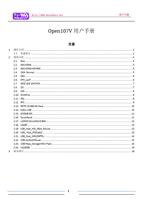
Open107V用户手册目录1. 硬件介绍 (2)1.1.资源简介 (2)2. 例程分析 (4)2.1. 8Ios (4)2.2. ADC+DMA (4)2.3. ADC+DMA+KEYPAD (5)2.4. CAN- Normal (5)2.5. DAC (6)2.6. ETH_LwIP (6)2.7. GPIO LED JOYSTICK (7)2.8. I2C (7)2.9. LCD (8)2.10. OneWire (9)2.11. PS2 (9)2.12. RTC (9)2.13. FATFS V0.08A-SD Card (10)2.14. SL811 USB (10)2.15. AT45DB-SPI (11)2.16. TouchPanel (11)2.17. uCOSII2.91+UCGUI3.90A (12)2.18. USART (13)2.19. USB_Host_HID_KBrd_Mouse (13)2.20. USB_ Host_MSC(efsl) (13)2.21. USB_Host_MSC(FATFS) (14)2.22. USB-JoyStickMouse (15)2.23. USB-Mass_Storage-MCU Flash (15)2.24. VS1003B (16)3. 版本修订 (16)1.硬件介绍1.1. 资源简介[ 芯片简介 ]1.STM32F107VCT6STM32功能强大,下面仅列出STM32F107VCT6的核心资源参数:内核:Cortex-M3 32-bit RISC;工作频率:72MHz,1.25 DMIPS/MHz;工作电压:2-3.6V;封装:LQFP100;I/O口:80;存储资源:256kB Flash,64kB RAM;接口资源:3 x SPI,3 x USART,2 x UART,2 x I2S,2 x I2C;1 x Ethernet MAC,1 x USB OTG,2 x CAN;模数转换:2 x AD(12位,1us,分时16通道),[ 其它器件简介 ]3."5V DC"或"USB"供电选择开关切换到上面,选择5V DC供电;切换到下面,选择USB供电。
STM32的八种GPIO工作方式详解

STM32的八种GPIO工作方式详解STM32的GPIO介绍STM32引脚说明GPIO是通用输入/输出端口的简称,是STM32可控制的引脚。
GPIO的引脚与外部硬件设备连接,可实现与外部通讯、控制外部硬件或者采集外部硬件数据的功能。
STM32F103ZET6芯片为144脚芯片,包括7个通用目的的输入/输出口(GPIO)组,分别为GPIOA、GPIOB、GPIOC、GPIOD、GPIOE、GPIOF、GPIOG,同时每组GPIO口组有16个GPIO口。
通常简略称为PAx、PBx、PCx、PDx、PEx、PFx、PGx,其中x为0-15。
STM32的大部分引脚除了当GPIO使用之外,还可以复用位外设功能引脚(比如串口),这部分在【STM32】STM32端口复用和重映射(AFIO辅助功能时钟) 中有详细的介绍。
GPIO基本结构每个GPIO内部都有这样的一个电路结构,这个结构在本文下面会具体介绍。
这边的电路图稍微提一下:保护二极管:IO引脚上下两边两个二极管用于防止引脚外部过高、过低的电压输入。
当引脚电压高于VDD时,上方的二极管导通;当引脚电压低于VSS时,下方的二极管导通,防止不正常电压引入芯片导致芯片烧毁。
但是尽管如此,还是不能直接外接大功率器件,须加大功率及隔离电路驱动,防止烧坏芯片或者外接器件无法正常工作。
P-MOS管和N-MOS管:由P-MOS管和N-MOS管组成的单元电路使得GPIO具有“推挽输出”和“开漏输出”的模式。
这里的电路会在下面很详细地分析到。
TTL肖特基触发器:信号经过触发器后,模拟信号转化为0和1的数字信号。
但是,当GPIO引脚作为ADC采集电压的输入通道时,用其“模拟输入”功能,此时信号不再经过触发器进行TTL电平转换。
ADC外设要采集到的原始的模拟信号。
这里需要注意的是,在查看《STM32中文参考手册V10》中的GPIO的表格时,会看到有“FT”一列,这代表着这个GPIO口时兼容3.3V和5V的;如果没有标注“FT”,就代表着。
STM32F429IGT6数据手册_引脚图_参数

STM32F429xx ARM Cortex-M432b MCU+FPU,225DMIPS,up to2MB Flash/256+4KB RAM,USBOTG HS/FS,Ethernet,17TIMs,3ADCs,20comm.interfaces,camera&LCD-TFTData brief Features•Core:ARM32-bit Cortex™-M4CPU with FPU,Adaptive real-time accelerator(ARTAccelerator™)allowing0-wait state executionfrom Flash memory,frequency up to180MHz, MPU,225DMIPS/1.25DMIPS/MHz(Dhrystone2.1),and DSP instructions •Memories–Up to2MB of Flash memory organized into two banks allowing read-while-write –Up to256+4KB of SRAM including64-KB of CCM(core coupled memory)data RAM –Flexible external memory controller with up to32-bit data bus:SRAM,PSRAM,SDRAM,Compact Flash/NOR/NAND memories •LCD parallel interface,8080/6800modes •LCD-TFT controller up to VGA resolution with dedicated Chrom-ART Accelerator™forenhanced graphic content creation(DMA2D)•Clock,reset and supply management– 1.8V to3.6V application supply and I/Os–POR,PDR,PVD and BOR–4-to-26MHz crystal oscillator–Internal16MHz factory-trimmed RC(1% accuracy)–32kHz oscillator for RTC with calibration–Internal32kHz RC with calibration•Low power–Sleep,Stop and Standby modes–V BAT supply for RTC,20×32bit backup registers+optional4KB backup SRAM •3×12-bit,2.4MSPS ADC:up to24channels and7.2MSPS in triple interleaved mode•2×12-bit D/A converters•General-purpose DMA:16-stream DMA controller with FIFOs and burst supportLQFP100(14×14mm)LQFP144(20×20mm)UFBGA176(10×10mm)LQFP176(24×24mm)TFBGA216(13x13mm)WLCSP143 LQFP208(28x28mm)–Cortex-M4Embedded Trace Macrocell™•Up to168I/O ports with interrupt capability –Up to164fast I/Os up to84MHz–Up to1665V-tolerant I/Os•Up to21communication interfaces–Up to3×I2C interfaces(SMBus/PMBus)–Up to4USARTs/4UARTs(11.25Mbit/s, ISO7816interface,LIN,IrDA,modemcontrol)–Up to6SPIs(42Mbits/s),2with muxed full-duplex I2S for audio class accuracy viainternal audio PLL or external clock –1x SAI(serial audio interface)–2×CAN(2.0B Active)and SDIO interface •Advanced connectivity–USB2.0full-speed device/host/OTGcontroller with on-chip PHY–USB2.0high-speed/full-speeddevice/host/OTG controller with dedicatedDMA,on-chip full-speed PHY and ULPI –10/100Ethernet MAC with dedicated DMA: supports IEEE1588v2hardware,MII/RMII •8-to14-bit parallel camera interface up to 54MBs/s•True random number generator•CRC calculation unit•96-bit unique ID•RTC:subsecond accuracy,hardware calendarTable1.Device summaryReference Part number•Up to17timers:up to twelve16-bit and two32-bit timers up to180MHz,each with up to4IC/OC/PWM or pulse counter and quadrature STM32F429xxSTM32F429VG,STM32F429ZG,STM32F429IG,STM32F429VI,STM32F429ZI,STM32F429II,STM32F429BG,STM32F429BI,STM32F429NI,STM32F429NG(incremental)encoder input•Debug mode–SWD&JTAG interfacesMay2013Doc ID023140Rev21/102 For further information contact your local STMicroelectronics sales office.Contents STM32F429xx Contents1Introduction (7)2Description (8)2.1Full compatibility throughout the family (11)3Functional overview (14)3.1ARM®Cortex™-M4with FPU and embedded Flash and SRAM (14)3.2Adaptive real-time memory accelerator(ART Accelerator™) (14)3.3Memory protection unit (14)3.4Embedded Flash memory (15)3.5CRC(cyclic redundancy check)calculation unit (15)3.6Embedded SRAM (15)3.7Multi-AHB bus matrix (15)3.8DMA controller(DMA) (16)3.9Flexible memory controller(FMC) (17)3.10LCD-TFT controller (17)3.11Chrom-ART Accelerator™(DMA2D) (18)3.12Nested vectored interrupt controller(NVIC) (18)3.13External interrupt/event controller(EXTI) (18)3.14Clocks and startup (18)3.15Boot modes (19)3.16Power supply schemes (19)3.17Power supply supervisor (19)3.17.1Internal reset ON (19)3.17.2Internal reset OFF (20)3.18Voltage regulator (21)3.18.1Regulator ON (21)3.18.2Regulator OFF (22)3.18.3Regulator ON/OFF and internal reset ON/OFF availability (25)3.19Real-time clock(RTC),backup SRAM and backup registers (25)3.20Low-power modes (26)3.21V BAT operation (27)2/102Doc ID023140Rev2STM32F429xx Contents3.22Timers and watchdogs (27)3.22.1Advanced-control timers(TIM1,TIM8) (28)3.22.2General-purpose timers(TIMx) (29)3.22.3Basic timers TIM6and TIM7 (29)3.22.4Independent watchdog (29)3.22.5Window watchdog (29)3.22.6SysTick timer (30)3.23Inter-integrated circuit interface(I2C) (30)3.24Universal synchronous/asynchronous receiver transmitters(USART)..303.25Serial peripheral interface(SPI) (31)3.26Inter-integrated sound(I2S) (31)3.27Serial Audio interface(SAI1) (32)3.28Audio PLL(PLLI2S) (32)3.29Audio and LCD PLL(PLLSAI) (32)3.30Secure digital input/output interface(SDIO) (32)3.31Ethernet MAC interface with dedicated DMA and IEEE1588support (33)3.32Controller area network(bxCAN) (33)3.33Universal serial bus on-the-go full-speed(OTG_FS) (34)3.34Universal serial bus on-the-go high-speed(OTG_HS) (34)3.35Digital camera interface(DCMI) (35)3.36Random number generator(RNG) (35)3.37General-purpose input/outputs(GPIOs) (35)3.38Analog-to-digital converters(ADCs) (35)3.39Temperature sensor (36)3.40Digital-to-analog converter(DAC) (36)3.41Serial wire JTAG debug port(SWJ-DP) (36)3.42Embedded Trace Macrocell™ (36)4Pinouts and pin description (38)5Memory mapping (76)6Package characteristics (81)6.1Package mechanical data (81)6.2Thermal characteristics (94)Doc ID023140Rev23/102Contents STM32F429xx 7Part numbering (95)Appendix A Application block diagrams (96)A.1USB OTG full speed(FS)interface solutions (96)A.2USB OTG high speed(HS)interface solutions (98)A.3Ethernet interface solutions (99)8Revision history (101)4/102Doc ID023140Rev2STM32F429xx List of tables List of tablesT able1.Device summary (1)T able2.STM32F429xx features and peripheral counts (9)T able3.Voltage regulator configuration mode versus device operating mode (22)T able4.Regulator ON/OFF and internal reset ON/OFF availability (25)T able5.Voltage regulator modes in stop mode (26)T able6.Timer feature comparison (28)T parison of I2C analog and digital filters (30)T ART feature comparison (31)T able9.Legend/abbreviations used in the pinout table (45)T able10.STM32F429xx pin and ball definitions (46)T able11.FMC pin definition (62)T able12.STM32F429xx alternate function mapping (65)T able13.STM32F429xx register boundary addresses (77)T able14.LQPF100,14x14mm100-pin low-profile quad flat package mechanical data (82)T able15.WLCSP143,0.4mm pitch wafe level chip scale package mechanical data (85)T able16.LQFP144,20x20mm,144-pin low-profile quad flat packagemechanical data (86)T able17.LQFP176,24x24mm,176-pin low-profile quad flat packagemechanical data (88)T able18.LQFP208,28x28mm,208-pin low-profile quad flat packagemechanical data (90)T able19.UFBGA176+25-ultra thin fine pitch ball grid array10×10×0.6mmmechanical data (92)T able20.TFBGA216-ultra thin fine pitch ball grid array13×13×0.8mmpackage mechanical data (93)T able21.Package thermal characteristics (94)T able22.Ordering information scheme (95)T able23.Document revision history (101)Doc ID023140Rev25/102STM32F429xxpatible board design STM32F10xx/STM32F2xx/STM32F4xxfor LQFP100package (11)patible board design between STM32F10xx/STM32F2xx/STM32F4xxfor LQFP144package (12)patible board design between STM32F2xx and STM32F4xxfor LQFP176package (12)Figure4.STM32F429xx block diagram (13)Figure5.STM32F429xx Multi-AHB matrix (16)Figure6.Power supply supervisor interconnection with internal reset OFF (20)Figure7.PDR_ON control with internal reset OFF (21)Figure8.Regulator OFF (23)Figure9.Startup in regulator OFF:slow V DD slope-power-down reset risen after V CAP_1/V CAP_2stabilization (24)Figure10.Startup in regulator OFF mode:fast V DD slope-power-down reset risen before V CAP_1/V CAP_2stabilization (24)Figure11.STM32F42x LQFP100pinout (38)Figure12.STM32F42x WLCSP143pinout (39)Figure13.STM32F42x LQFP144pinout (40)Figure14.STM32F42x LQFP176pinout (41)Figure15.STM32F42x LQFP208pinout (42)Figure16.STM32F42x UFBGA176ballout (43)Figure17.STM32F42x TFBGA216ballout (44)Figure18.Memory map (76)Figure19.LQFP100,14x14mm100-pin low-profile quad flat package outline (81)Figure20.LQPF100recommended footprint (83)Figure21.WLCSP143,0.4mm pitch wafe level chip scale package outline (84)Figure22.LQFP144,20x20mm,144-pin low-profile quad flat package outline (86)Figure23.LQFP144recommended footprint (87)Figure24.LQFP17624x24mm,176-pin low-profile quad flat package outline (88)Figure25.LQFP176recommended footprint (89)Figure26.LQFP208,28x28mm,208-pin low-profile quad flat package outline (90)Figure27.LQFP208recommended footprint (91)Figure28.UFBGA176+25-ultra thin fine pitch ball grid array10×10×0.6mm,package outline (92)Figure29.TFBGA216-ultra thin fine pitch ball grid array13×13×0.8mm,package outline (93)B controller configured as peripheral-only and usedin Full speed mode (96)B controller configured as host-only and used in full speed mode (96)B controller configured in dual mode and used in full speed mode (97)B controller configured as peripheral,host,or dual-modeand used in high speed mode (98)Figure34.MII mode using a25MHz crystal (99)Figure35.RMII with a50MHz oscillator (99)Figure36.RMII with a25MHz crystal and PHY with PLL (100)6/102Doc ID023140Rev2STM32F429xx Introduction 1IntroductionThis databrief provides the description of the STM32F429xx line of microcontrollers.Formore details on the whole STMicroelectronics STM32™family,please refer to Section2.1:Full compatibility throughout the family.The STM32F429xx databrief should be read in conjunction with the STM32F4xx referencemanual.For information on the Cortex™-M4core,please refer to the Cortex™-M4programmingmanual(PM0214),available from the web.Doc ID023140Rev27/102Description STM32F429xx 2DescriptionThe STM32F429XX devices is based on the high-performance ARM®Cortex™-M432-bitRISC core operating at a frequency of up to180MHz.The Cortex-M4core features aFloating point unit(FPU)single precision which supports all ARM single-precision data-processing instructions and data types.It also implements a full set of DSP instructions anda memory protection unit(MPU)which enhances application security.The STM32F429xx devices incorporates high-speed embedded memories(Flash memoryup to2Mbyte,up to256Kbytes of SRAM),up to4Kbytes of backup SRAM,and anextensive range of enhanced I/Os and peripherals connected to two APB buses,two AHBbuses and a32-bit multi-AHB bus matrix.All devices offer three12-bit ADCs,two DACs,a low-power RTC,twelve general-purpose16-bit timers including two PWM timers for motor control,two general-purpose32-bit timers.a true random number generator(RNG).They also feature standard and advancedcommunication interfaces.•Up to three I2Cs•Six SPIs,two I2Ss full duplex.T o achieve audio class accuracy,the I2S peripherals can be clocked via a dedicated internal audio PLL or via an external clock to allowsynchronization.•Four USART s plus four UARTs•An USB OTG full-speed and a USB OTG high-speed with full-speed capability(with the ULPI),•Two CANs•One SAI serial audio interface•An SDIO/MMC interface•Ethernet and the camera interface•LCD-TFT display controller•DMA2D controller.Advanced peripherals include an SDIO,a flexible memory control(FMC)interface,acamera interface for CMOS sensors.Refer to T able2:STM32F429xx features andperipheral counts for the list of peripherals available on each part number.The STM32F429xx devices operates in the–40to+105°C temperature range from a1.8to3.6V power supply.The supply voltage can drop to1.7V when the device operates in the0to70°Ctemperature range with the use of an external power supply supervisor(refer toSection3.17.2:Internal reset OFF).A comprehensive set of power-saving mode allows thedesign of low-power applications.The STM32F429xx devices offers devices in7packages ranging from100pins to216pins.The set of included peripherals changes with the device chosen.8/102Doc ID023140Rev29/102 DocID023140Rev2DescriptionSTM32F429xxThese features make the STM32F429xx microcontrollers suitable for a wide range of applications: • Motor drive and application control • Medical equipment• Industrial applications: PLC, inverters, circuit breakers • Printers, and scanners• Alarm systems, video intercom, and HVAC •Home audio appliancesFigure 4 and Figure 4 show the general block diagram of the device family .Table 2. STM32F429xx features and peripheral countsPeripheralsSTM32F429Vx STM32F429Zx STM32F429Ix STM32F429Bx STM32F429Nx Flash memory in Kbytes 1024204810242048102420481024204810242048SRAM in KbytesSystem 256(112+16+64+64)Backup4 FMC memory controller Y es (1) EthernetY esTimersGeneral-purpose10 Advanced-control 2 Basic2 Random number generatorY es Communication interfaces2SPI / I S 6/2 (full duplex)(2)2I C3 USART/UART 4/4 USB OTG FS Y es USB OTG HS Y es CAN 2 SAI 1 SDIOY esDocID023140Rev2 10/102STM32F429xxDescription Table2.STM32F429xx features and peripheral counts(continued)1.For the LQFP100package,only FMC Bank1or Bank2are available.Bank1can only support a multiplexed NOR/PSRAM memory using the NE1ChipSelect.Bank2can only support a16-or8-bit NAND Flash memory using the NCE2Chip Select.The interrupt line cannot be used since Port G is notavailable in this package.2.The SPI2and SPI3interfaces give the flexibility to work in an exclusive way in either the SPI mode or the I2S audio mode.3.V DD/V DDA minimum value of1.7V is obtained when the device operates in reduced temperature range,and with the use of an external power supplysupervisor(refer to Section3.17.2:Internal reset OFF).Peripherals STM32F429Vx STM32F429Zx STM32F429Ix STM32F429Bx STM32F429NxCamera interface Y esLCD-TFT Y esChrom-ART Accelerator™(DMA2D)Y esGPIOs8211414016812-bit ADCNumber of channels316242412-bit DACNumber of channelsY es2Maximum CPU frequency180MHzOperating voltage 1.8to3.6V(3)Operating temperaturesAmbient temperatures:–40to+85°C/–40to+105°CJunction temperature:–40to+125°CPackages LQFP100WLCSP143LQFP144UFBGA176LQFP176LQFP208TFBGA216STM32F429xx Description 2.1Full compatibility throughout the familyThe STM32F429xx devices are part of the STM32F4family.They are fully pin-to-pin,software and feature compatible with the STM32F2xx devices,allowing the user to trydifferent memory densities,peripherals,and performances(FPU,higher frequency)for agreater degree of freedom during the development cycle.The STM32F429xx devices maintain a close compatibility with the whole STM32F10xxfamily.All functional pins are pin-to-pin compatible.The STM32F429xx,however,are notdrop-in replacements for the STM32F10xx devices:the two families do not have the samepower scheme,and so their power pins are different.Nonetheless,transition from theSTM32F10xx to the STM32F42x family remains simple as only a few pins are impacted.Figure1,Figure2,and Figure3,give compatible board designs between the STM32F4xx,STM32F2xx,and STM32F10xx families.patible board design STM32F10xx/STM32F2xx/STM32F4xxfor LQFP100package∧∧Doc ID023140Rev211/102Description STM32F429xxpatible board design between STM32F10xx/STM32F2xx/STM32F4xxfor LQFP144package109108106V SS737172V SSV SS0Ωresistor or soldering bridgeSignal fromexternal powersupplysupervisor144143(PDR_ON)303137present for the STM32F10xxconfiguration,not present in theSTM32F4xx configuration136V DD V SSV SSTwo0Ωresistors connected to:-V SS for the STM32F10xx V DD V SS V SS for STM32F10xx V DD for STM32F4xx-V SS,V DD or NC for the STM32F2xx-V DD or signal from external power supply supervisor for the STM32F4xxpatible board design between STM32F2xx and STM32F4xxai18487d133132898848-GND for STM32F2xx-BYPASS_REG for STM32F4xxSignal from externalpower supply171(PDR_ON)supervisor17645144V DD V SSTwo0Ωresistors connected to:-V SS,V DD or NC for the STM32F2xx-V DD or signal from external power supply supervisor for the STM32F4xxMS31835V1 12/102Doc ID023140Rev2STM32F429xx DescriptionFigure4.STM32F429xx block diagram1.The timers connected to APB2are clocked from TIMxCLK up to180MHz,while the timers connected to APB1are clockedfrom TIMxCLK either up to90MHz or180MHz depending on TIMPRE bit configuration in the RCC_DCKCFGR register.Doc ID023140Rev213/102Functional overview STM32F429xx 3Functional overview3.1ARM®Cortex™-M4with FPU and embedded Flash andSRAMThe ARM Cortex-M4with FPU processor is the latest generation of ARM processors forembedded systems.It was developed to provide a low-cost platform that meets the needs ofMCU implementation,with a reduced pin count and low-power consumption,whiledelivering outstanding computational performance and an advanced response to interrupts.The ARM Cortex-M4with FPU core is a32-bit RISC processor that features exceptionalcode-efficiency,delivering the high-performance expected from an ARM core in the memorysize usually associated with8-and16-bit devices.The processor supports a set of DSP instructions which allow efficient signal processing andcomplex algorithm execution.Its single precision FPU(floating point unit)speeds up software development by usingmetalanguage development tools,while avoiding saturation.The STM32F42x family is compatible with all ARM tools and software.Figure4shows the general block diagram of the STM32F42x family.Note:Cortex-M4with FPU core is binary compatible with the Cortex-M3core.3.2Adaptive real-time memory accelerator(ART Accelerator™)The ART Accelerator™is a memory accelerator which is optimized for STM32industry-standard ARM®Cortex™-M4with FPU processors.It balances the inherent performanceadvantage of the ARM Cortex-M4with FPU over Flash memory technologies,whichnormally requires the processor to wait for the Flash memory at higher frequencies.T o release the processor full225DMIPS performance at this frequency,the acceleratorimplements an instruction prefetch queue and branch cache,which increases programexecution speed from the128-bit Flash memory.Based on CoreMark benchmark,theperformance achieved thanks to the ART Accelerator is equivalent to0wait state programexecution from Flash memory at a CPU frequency up to180MHz.3.3Memory protection unitThe memory protection unit(MPU)is used to manage the CPU accesses to memory toprevent one task to accidentally corrupt the memory or resources used by any other activetask.This memory area is organized into up to8protected areas that can in turn be dividedup into8subareas.The protection area sizes are between32bytes and the whole4gigabytes of addressable memory.The MPU is especially helpful for applications where some critical or certified code has to beprotected against the misbehavior of other tasks.It is usually managed by an RTOS(real-time operating system).If a program accesses a memory location that is prohibited by theMPU,the RTOS can detect it and take action.In an RTOS environment,the kernel candynamically update the MPU area setting,based on the process to be executed.14/102Doc ID023140Rev2采购电子元器件选择万联芯城,万联芯城是国内一家知名电子元器件网上商城,专为终端研发客户提供电子元器件一站式配套服务,万联芯城只售原装现货电子元器件,货源渠道均来自原厂及授权代理商,品质有保证,价格有优势,为客户节省采购成本。
Excel格式的STM32F20x系列引脚表

2. FT = 5 V tolerant; TT =3.6 V tolerant.3. Function availability depends on the chosen device.4. PC13, PC14, PC15 and PI8 are supplied through the power switch. Since the switch only sinks a limited amount of current (3 mA), the u5. Main function after the first backup domain power-up. Later on, it depends on the contents of the RTC registers even after reset (because6. FT = 5 V tolerant except when in analog mode or oscillator mode (for PC14, PC15, PH0 and PH1).7. If the device is delivered in an UFBGA176 package and if the REGOFF pin is set to V DD (Regulator OFF), then PA0 is used as an internal Reset (active low8. FSMC_NL pin is also named FSMC_NADV on memory devices.9. RFU means “reserved for future use”. This pin can be tied to V DD,V SS or left unconnected.the use of GPIOs PC13 to PC15 and PI8 in output modause these registers are not reset by the main reset). Fo used as an internal Reset (active low).t mode is limited: the speed should not exceed 2 MHz with a maximum load of 30 pF and these I/Os must not be used as a current source (e.g. to drive et). For details on how to manage these I/Os, refer to the RTC register description sections in the STM32F20x and STM32F21x reference manual, availo drive an LED)., available from the STMicroelectronics website: .。
STM32 GPIO教程

系统外设
GPIO特性
最大封装(64引脚)上多达55个多功能双向GPIO(GPIO 引脚占有率相比STM32F1系列的80%更增加到86%) 几乎所有GPIO都是5V容忍(ADC引脚除外) GPIO分布在5个端口上:GPIOA[0~15]、GPIOB[0~15]、 GPIOC[0~15]、GPIOD[0~2]、GPIOF[4~7] 使用BSRR和BRR寄存器可以完成对引脚的原子置位和 复位操作 GPIO连在AHB总线,使得最高翻转速度高达12MHz 输出斜率可配置,高达50MHz 端口A和B上的引脚配置可通过LCKR寄存器锁定 55个引脚都可以配置成外部中断(可同时使能16个) 来把MCU从停止模式唤醒
I2C1端口支持1MHz超快速总线【FTf】
PB6/7 (I2C1_SCL/SDA) PB8/9 (I2C1_SCL/SDA)
其余端口都是5V容忍【FT】
10
Quiz
How many I/Os and ports there are in the STM32F0xx microcontroller ? ____________
可编程复用开关使得任意时刻只有一个外设连到 某个具体的GPIO。只有GPIOA和GPIOB有复用开关 某些外设功能还可以重映射到其他引脚,从而使 得能同时使用的外设数量更多
AF0 (SPI1_MISO) AF1 (TIM3_CH1) AF2 (TIM1_BKIN) Pin x (0…7)
AF7 (COMP1_OUT)
Output Driver
VSS
Push-Pull Open Drain
* In output mode, the I/O speed is configurable through OSPEEDR register: 2MHz, 10MHz or 50MHz
STM32开发板IO引脚分配说明表(大板)
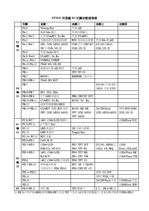
STM32开发板IO 引脚分配说明表引脚 功能一 功能二 功能三 功能四 PA.0 Wakeup Key外部AD PA.1 板载Mic 输入 外部音频输入PA.2, PA.3 红外USART2_Tx, Rx 外部USART2 PA.4 光敏电阻光线强弱监测 RTC 电池电压监测外部DA 或ADPA.5~PA.7 SPI1_SCK, MISO, MOSI SD 卡CLK, SO, SI USB 芯片CH376TCLK, SO, SI CC1101/24L01: CLK, SO, SI PA.8 外部Audio 输出 PA.9, PA10 USART1_Tx, Rx PA.11, PA12 USBDM, USBDP PA 端口PA.13~PA.15 JTAG_MS, CK, DIPB.0板载电位器AD 测试外部AD PB.1 TFT: TP_CS PB.2 BOOT1 BEEPER (带开关) PB.3~PB.4 JTAG_DO, RSTPB.5 CC1101片选(CS ) 24L01片选(CSN ) PB.6~PB.7 IIC1_SCL, SDAPB.8~PB.9 2个LED 状态灯 PB9: CH376T_INTPB.10~PB.11 USART3_Tx, Rx RS485_Tx 、RxPB.12温度传感器DS18B20PB端口PB.13~PB.15 USART3_CTS, RTS 流控SPI2_SCK, MISO, MOSIRS485_RE, DETFT_SCK, MISO TFT_MOSI2M SPI Flash: SCK, MISO,MOSI 网络ENC28J60SCK, SO, SI PC.0~PC.7 1602, 12864 LCD 数据口128MFlash 数据PC.8~PC.11 4个独立Key PC.12 LED 状态灯 SD 卡插入检测PC.13 LED 状态灯 Tamper KeyPC 端口 PC.14~ PC.15 RTC 晶振 PD.0~PD.1 CAN_R, DPD.2~PD.3 12864 LCDPSB/CS1, NC/CS2 PD2: TFT_INT PD3: TFT_RS CC1101_GDO0, 2 24L01_CE, IRQ128MFlash_CLE,ALEPD.4~PD.5 1602, 12864 LCDR/I, R/W PD4: TFT_RD PD5: TFT_WR 128M Flash_RE128M Flash_WE PD.6 1602, 12864 LCD 片选CS PD6: TFT_CS PD.7~PD.10舵机输出控制目前仅用了PD9, PD10PD7: SD 卡CD/D3PD8: CH376T_CSPD.11~PD12 网络_CS, INT PD.13 网络_WOL 中断PD.142M SPI Flash 片选 128MFlash 片选PD 端口PD.15128MFlash_R/BPE PE.0~PE.15外扩IO TFT 数据口8位:PE.8~PE.15注:PE 端口作扩展GPIO 使用PE0~PE7,以及TFT 工作在16位模式的数据口,若8位模式则使用PE8~PE15。
STM32F407ZGT6引脚功能定义

Pin Pin Pin Pin Pin Pin
450 -350 450 -340 450 -330 450 -320 450 -310 450 -300
0 Degrees 0 Degrees 0 Degrees 0 Degrees 0 Degrees 0 Degrees
74 75 76 77 78 79
Pin Pin Pin Pin Pin Pin Pin Pin Pin Pin Pin Pin Pin Pin Pin Pin Pin Pin Pin Pin Pin Pin Pin Pin Pin Pin Pin Pin Pin Pin Pin Pin Pin Pin Pin Pin Pin Pin Pin Pin Pin Pin Pin Pin
PA0180 Degrees WKUP/USART2_CTS/UART4_TX/ETH_MII_CRS/TIM2_CH1_ETR/TI M5_CH1/TIM8_ETR/ADC123_IN0 180 Degrees 180 Degrees 180 Degrees 180 Degrees 180 Degrees 180 Degrees PA1/USART2_RTS/UART4_RX/ETH_RMII_REF_CLK/ETH_MII_RX_C LK/TIM5_CH2/TIM2_CH2/ADC123_IN1 PA2/USART2_TX/TIM5_CH3/TIM9_CH1/TIM2_CH3/ETH_MDIO/ ADC123_IN2 PA3/USART2_RX/TIM5_CH4/TIM9_CH2/TIM2_CH4/OTG_HS_UL PI_D0/ETH_MII_COL/ADC123_IN3 VSS VDD PA4/SPI1_NSS/SPI3_NSS/USART2_CK/DCMI_HSYNC/OTG_HS_S OF/I2S3_WS/ADC12_IN4/DAC_OUT1
STM32F74xxx STM32F75xxx 硬件开发入门说明书
2
引脚复用映射 . . . . . . . . . . . . . . . . . . . . . . . . . . . . . . . . . . . . . . . . . . . . . . . 17
3
时钟 . . . . . . . . . . . . . . . . . . . . . . . . . . . . . . . . . . . . . . . . . . . . . . . . . . . . . . 18串行接口和 JTAG) . . . . . . . . . . . . . . . . . . . . . . . . . . . . 23 5.3 引脚排列和调试端口引脚 . . . . . . . . . . . . . . . . . . . . . . . . . . . . . . . . . . . . . 23
1.3.4 内部复位 ON . . . . . . . . . . . . . . . . . . . . . . . . . . . . . . . . . . . . . . . . . . . . . 13
1.3.5 内部复位 OFF . . . . . . . . . . . . . . . . . . . . . . . . . . . . . . . . . . . . . . . . . . . . 13
3.3 时钟安全系统 (CSS) . . . . . . . . . . . . . . . . . . . . . . . . . . . . . . . . . . . . . . . . . 20
4
启动配置 . . . . . . . . . . . . . . . . . . . . . . . . . . . . . . . . . . . . . . . . . . . . . . . . . . 21
通用输入输出端口GPIO

PortG (16)
PortH (16) PortI (12) 总共引脚数目 48+1+2=51 80+2=82 112+2=114 128+12=140 PH0/1(OSC) PH0/1(OSC) PH0/1(OSC)
GPIO占芯片所有引脚的80% 左右
4
GPIO结构框图
数字外设
数字外设和 EVENTOUT
特殊I/O引脚说明 STM32F1和STM32F2的GPIO比较
2
培训内容
GPIO引脚分布和结构框图 I/O引脚的多路复用选择和映射 I/O引脚的8种配置模式
输入:浮空、上/下拉、模拟输入 输出:可配置上/下拉的推挽输出、开漏输出
I/O引脚的特色功能
引脚配置锁定 引脚上的位操作 I/O补偿单元
必须32位读写
19
GPIO位操作(1)
STM32Fቤተ መጻሕፍቲ ባይዱ位操作,两个寄存器,只支持字操作
GPIOx_BSRR[32] = Bri | Bsi (i=0~15) GPIOx_BRR[32] = Bri (i=0~15) e.g. 同时同向toggle PA.0和PA.1
>> GPIOA_BSRR = 0x03 >> GPIOA_BRR = 0x03 >> GPIOA_BSRR = 0x21 >> GPIOA_BSRR = 0x12
②
③ ① 输出驱动关闭 ② Schmit触发输入关闭 ③上/下拉电阻被禁止
①
Schmitt触发器关闭
该引脚功耗为0 触发器输出强制为常数0
读取输入数据寄存器始终得到”0” 模拟功能配置下,I/O引脚不是5V容忍
STM32F405RGT6数据手册_引脚图_参数

2.2.6 Embedded SRAM . . . . . . . . . . . . . . . . . . . . . . . . . . . . . . . . . . . . . . . . . 20
2.2.7 Multi-AHB bus matrix . . . . . . . . . . . . . . . . . . . . . . . . . . . . . . . . . . . . . . . 20
• Low power
– Sleep, Stop and Standby modes
–
rVeBgAisTtseurspp+lyopfotiroRnaTlC4,
20×32 bit backup KB backup SRAM
• 3×12-bit, 2.4 MSPS A/D converters: up to 24 channels and 7.2 MSPS in triple interleaved mode
• LCD parallel interface, 8080/6800 modes
• Clock, reset and supply management – 1.8 V to 3.6 V application supply and I/Os – POR, PDR, PVD and BOR – 4-to-26 MHz crystal oscillator – Internal 16 MHz factory-trimmed RC (1% accuracy) – 32 kHz oscillator for RTC with calibration – Internal 32 kHz RC with calibration
2.2.10 Nested vectored interrupt controller (NVIC) . . . . . . . . . . . . . . . . . . . . . . 22
stm32f407引脚分配表
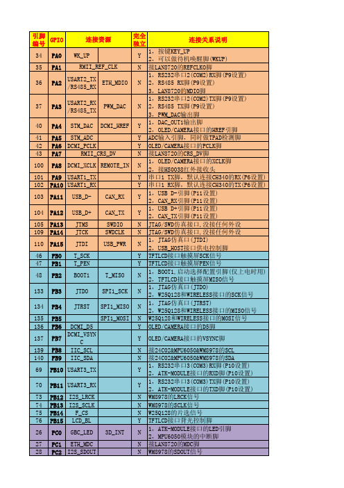
Y N N N N Y N N N N N N N N N N Y Y N N N N Y N N Y
PG9 DCMI_PWDN 1WIRE_DQ PG10 PG11 PG12 PG13 PG14 PG15 FSMC_NE3 RMII_TX_EN FSMC_NE4 RMII_TXD0 RMII_TXD1 DCMI_RESET
tftlcd接口触摸屏sck信号该io接tftlcd模块接口的触摸屏sck信号当不插tftlcd模块时该io完全独立tftlcd接口触摸屏pen信号该io接tftlcd模块接口的触摸屏pen信号中断当不插tftlcd模块时该io完全独立1boot1启动选择配置引脚仅上电时用2tftlcd接口触摸屏miso信号该io在上电时作boot1用由b1控制上拉下拉设置启动模式同时作为tftlcd模块接口的触摸屏miso信号如不插tftlcd模块则可做普通io用有10k上拉下拉b0控制1jtag仿真口jtdo2w25q128和wireless接口的sck信号jtag仿真接口也做spi1sck信号如不用jtag仿真接口和wireless接口不插外设即可并且禁止w25q128的片选信号则可以做普通io用1jtag仿真口jtrst2w25q128和wireless接口的miso信号jtag仿真接口也做spi1miso信号如不用jtag仿真接口和wireless接口不插外设即可并且禁止w25q128的片选信号则可以做普通io用w25q128和wireless接口的mosi信号spi1mosi信号当不使用w25q128片选禁止和wireless接口时可以做普通io用oledcamera接口的d5脚仅连接oledcamera接口的d5当不使用oledcamera接口时该io完全独立oledcamera接口的vsync脚仅连接oledcamera接口的vsync当不使用oledcamera接口时该io完全独立接24c02mpu6050wm8978的scl该io连接24c02mpu6050wm8978等的scl信号有47k上拉电阻不建议作为普通io使用接24c02mpu6050wm8978的sda该io连接24c02mpu6050wm8978等的sda信号有47k上拉电阻不建议作为普通io使用1rs232串口3com3rx脚p10设置2atkmodule接口的rxd脚p10设置该io通过p10选择连接rs232atkmodule接口去掉p10的跳线帽则该io完全独立这里的rs232rx脚是指sp3232芯片的rx脚接stm32的tx脚1rs232串口3com3tx脚p10设置2atkmodule接口的txd脚p10设置该io通过p10选择连接rs232atkmodule接口去掉p10的跳线帽则该io完全独立这里的rs232tx脚是指sp32
STM32之GPIO端口操作
STM32之GPIO端口操作/zhaojun_xf/blog/static/3005058020103 1071939477/2010最近看了(与ARM7相比Cortex-M3优势明显)。
手头正有套ST送的三合一开发板,准备正式学习STM32。
特转载以下内容进行学习。
最近刚开始学习STM32,所以从最基本的GPIO开始学起;首先看看STM32的datasheet上对GPIO口的简单介绍:每个GPI/O 端口有两个32 位配置寄存器(GPIOx_CRL,GPIOx_CRH),两个32位数据寄存器(GPIOx_IDR,GPIOx_ODR),一个32 位置位/复位寄存器(GPIOx_BSRR),一个16 位复位寄存器(GPIOx_BRR)和一个32 位锁定寄存器(GPIOx_LCKR)。
GPIO 端口的每个位可以由软件分别配置成多种模式。
每个I/O 端口位可以自由编程,然而I/0 端口寄存器必须按32 位字被访问(不允许半字或字节访问)。
GPIOx_BSRR 和GPIOx_BRR 寄存器允许对任何GPIO 寄存器的读/更改的独立访问;这样,在读和更改访问之间产生IRQ 时不会发生危险。
端口位配置 CNFx[1:0]=xxb,MODEx[1:0]=xxb再看GPIO功能很强大:1.通用I/O(GPIO):最最基本的功能,可以驱动LED、可以产生PWM、可以驱动蜂鸣器等等;2.单独的位设置或位清除:方便软体作业,程序简单。
端口配置好以后只需GPIO_SetBits(GPIOx, GPIO_Pin_x)就可以实现对GPIOx 的pinx位为高电平;3.外部中断/唤醒线:端口必须配置成输入模式时,所有端口都有外部中断能力;4.复用功能(AF):复用功能的端口兼有IO功能等。
复位期间和刚复位后,复用功能未开启,I/O 端口被配置成浮空输入模式:(CNFx[1:0]=01b,MODEx[1:0]=00b)。
5.软件重新映射I/O复用功能:为了使不同器件封装的外设I/O 功能的数量达到最优,可以把一些复用功能重新映射到其他一些脚上。
- 1、下载文档前请自行甄别文档内容的完整性,平台不提供额外的编辑、内容补充、找答案等附加服务。
- 2、"仅部分预览"的文档,不可在线预览部分如存在完整性等问题,可反馈申请退款(可完整预览的文档不适用该条件!)。
- 3、如文档侵犯您的权益,请联系客服反馈,我们会尽快为您处理(人工客服工作时间:9:00-18:30)。
TRACESWD
PB3
161
Not Use
NRST
NRST
31
18.SPDIF模块:
模块名称
引脚名称
LQFP176
备注
SPDIF
SPDIF_RX_IN0
PG11
154
SPDIF_RX_IN1
PG12
155
SPDIF_RX_IN2
PC4
54
SPDIF_RX_IN3
PC5
55
PC2
ADC123_IN13
PC3
ADC12_IN14
PC4
ADC12_IN15
PC5
ADC3_IN4
PF6
ADC3_IN5
PF7
ADC3_IN6
PF8
ADC3_IN7
PF9
ADC3_IN8
PF10
12.TIME模块:
模块名称
引脚名称
LQFP176
备注
TIM1
TIM1_CH1
PA8
TIM1_CH1N
SDRAM_A9
PF15
SDRAM_A10
PG0
SDRAM_A11
PG1
SDRAM_A12
PG2
SDRAM_BA0
PG4
SDRAM_BA1
PG5
SDRAM_D0
PD14
SDRAM _D1
PD15
SDRAM _D2
PD0
SDRAM _D3
PD1
SDRAM _D4
PE7
SDRAM _D5
PE8
SDRAM _D6
引脚名称
LQFP176
备注
SAI1
(CS43L22)
SAI1_FS_A
PE4
3
LRCK
SAI1_SCK_A
PE5
4
SCLK
SAI1_SD_A
PE6
5
SDIN
SAI1_MCLK_A
PE2
1
MCLK
SAI1_SD_B
PE3
2
SDOUT
11.ADC模块:
模块名称
引脚名称
LQFP176
备注
ADC
ADC123_IN0
备注
I2C2
I2C2_SCL
PB10
79
I2C2_SDA
PB11
80
4. SDIO模块:
模块名称
引脚名称
LQFP176
备注
SDIO
SDIO_D0
PC8
117
SDIO_D1
PC9
118
SDIO_D2
PC10
139
SDIO_D3
PC11
140
SDIO_CLK
PC12
141
SDIO_CMD
PD2
144
SDIO_TP
PB4
SPI3_MOSI
PB5
模块名称
引脚名称
LQFP176
备注
SPI4
SPI4_NSS
PE11
SPI4_SCK
PE12
SPI4_MISO
PE13
SPI4_MOSI
PE14
模块名称
引脚名称
LQFP176
备注
SPI5
SPI5_NSS
PF6
SPI5_SCK
PF7
SPI5_MISO
PF8
SPI5_MOSI
备注
USART3
USART3_TX
PB10
USART3_RX
PB11
模块名称
引脚名称
LQFP176
备注
USART4
USART4_TX
PA0
USART4_RX
PA1
模块名称
引脚名称
LQFP176
备注
USART5
USART5_TX
PC12
USART5_RX
PD2
8.DAC模块:
模块名称
引脚名称
LQFP176
PD0
FLASH _D3
PD1
FLASH _D4
PE7
FLASH _D5
PE8
FLASH _D6
PE9
FLASH _D7
PE10
FLASH_CLE
PD11
FLASH_ALE
PD12
FLASH_NCE
PG9
FLASH_NOE
PD4
FLASH_NWE
PD5
FLASH_NWAIT
PD6
FLASH_INT
PG7
PD7
LCD_RESET
???
14.SDRAM模块:
模块名称
引脚名称
LQFP176
备注
SDRAM
SDRAM_A0
PF0
SDRAM_A1
PF1
SDRAM_A2
PF2
SDRAM_A3
PF3
SDRAM_A4
PF4
SDRAM_A5
PF5
SDRAM_A6
PF12
SDRAM_A7
PF13
SDRAM_A8
PF14
PE9
SDRAM _D7
PE10
SDRAM _D8
PE11
SDRAM _D9
PE12
SDRAM _D10
PE13
SDRAM _D11
PE14
SDRAM _D12
PE15
SDRAM _D13
PD8
SDRAM _D14
PD9
SDRAM _D15
PD10
SDRAM_NBL0
PE0
SDRAM_NBL1
PE1
PC8
TIM8_CH3N
PB1
TIM8_CH4
PC9
TIM8_BKIN
PA6
TIM8_ETR
PA0
13.FMC _LCD模块:
模块名称
引脚名称
LQFP176
备注
FMC--
LCD
FMC_D0
PD14
FMC_D1
PD15
FMC_D2
PD0
FMC_D3
PD1
FMC_D4
PE7
FMC_D5
PE8
FMC_D6
CAN1
CAN1_RX
PA11
CAN1_TX
PA12
7. USART模块:
模块名称
引脚名称
LQFP176
备注
USART1
USART1_TX
PA9
120
USART1_RX
PA10
121
模块名称
引脚名称
LQFP176
备注
USART2
USART2_TX
PA2
USART2_RX
PA3
模块名称
引脚名称
LQFP176
??
SD卡检测
5. USB模块:
模块名称
引脚名称
LQFP176
备注
USB-FS
USB_DM/D-
PA11
122
USB_DP/D+
PA12
123
模块名称
引脚名称
LQFP176
备注
USB-HS
USB_DM/D-
PB14
94
USB_DP/D+
PB15
95
6. CAN模块:
模块名称
引脚名称
LQFP176
备注
TIM4_ETR
PE0
模块名称
引脚名称
LQFP176
备注
TIM5
TIM5_CH1
PA0
TIM5_CH2
PA1
TIM5_CH3
PA2
TIM5_CH4
PA3
模块名称
引脚名称
LQFP176
备注
TIM8
TIM8_CH1
PC6
TIM8_CH1N
PA7
TIM8_CH2
PC7
TIM8_CH2N
PB0
TIM8_CH3
PB13
TIM1_CH2
PA9
TIM1_CH2N
PB14
TIM1_CH3
PA10
TIM1_CH3N
PB15
TIM1_CH4
PA11
TIM1_BKIN
PB12
TIM1_ETR
PA12
模块名称
引脚名称
LQFP176
备注
TIM2
TIM2_CH1 / ETR
PA0
TIM2_CH2
PA1
TIM2_CH3
PA2
SDRAM_CLK
PG8
SDRAM_NWE
PC0
SDRAM_NRAS
PF11
SDRAM_NCAS
PG15
SDRAM_CKE0
2
SDRAM_NE0
PH3
15.NAND_FLASH模块:
模块名称
引脚名称
LQFP176
备注
NAND--
FLASH
FLASH_D0
PD14
FLASH _D1
PD15
FLASH _D2
备注
DAC
DAC_OUT1
PA4
50
DAC_OUT2
PA5
51
9.I2S模块:
模块名称
引脚名称
LQFP176
备注
I2S1
I2S1_WS
PA15
I2S1_SCK
PB3
I2S1_SD
PB5
I2S1_MCK
PC4
模块名称
