TS-500说明书(新)
500系列话筒前置放大器502快速入门指南说明书

500 SERIES MICROPHONE PREAMPLIFIER 502 500 Series Modular Midas Microphone Preamplifier with Classic XL4 FiltersV 1.0带有此标志的终端设备具有强大的电流, 存在触电危险。
仅限使用带有 1/4'' TS 或扭锁式插头的高品质专业扬声器线。
所有的安装或调整均须由合格的专业人员进行。
此标志提醒您,产品内存在未绝缘的危险电压, 有 触电危险。
此标志提醒您查阅所附的重要的使用及维修说明。
请阅读有关手册。
小心为避免触电危险, 请勿打开机顶盖 (或背面挡板)。
设备内没有可供用户维修使用的部件。
请将维修事项交由合格的专业人员进行。
小心为避免着火或触电危险, 请勿将此设备置于雨淋或潮湿中。
此设备也不可受液体滴溅, 盛有液体的容器也不可置于其上, 如花瓶等。
小心维修说明仅是给合格的专业维修人员使用的。
为 避免触电危险, 除了使用说明书提到的以外, 请勿进行任何其它维修。
所有维修均须由合格的专业人员进行。
1. 请阅读这些说明。
2. 请妥善保存这些说明。
3. 请注意所有的警示。
4. 请遵守所有的说明。
5. 请勿在靠近水的地方使用本产品。
6. 请用干布清洁本产品。
7. 请勿堵塞通风口。
安装本产品时请遵照厂家的说明。
8. 请勿将本产品安装在热源附近, 如 暖气片, 炉子或其它产生热量的设备 ( 包括功放器)。
9. 请勿移除极性插头或接地插头的安全装置。
接地插头是由两个插塞接点及一个接地头构成。
若随货提供的插头不适合您的插座, 请找电工更换一个合适的插座。
10. 妥善保护电源线, 使其不被践踏或刺破, 尤其注意电源插头、多用途插座及设备连接处。
11. 请只使用厂家指定的附属设备和配 件。
12. 请只使用厂家指定的或随货销售的手推车, 架子, 三 角架, 支架和桌子。
若使用手推车来搬运设备, 请注意安全放置设备, 以 避免手推车和设备倾倒而受伤。
浪潮全产品手册.pdf说明书

浪潮全产品手册浪潮服务器关键应用主机高性能人工智能英信服务器统一存储天梭M13天梭TS860G3天梭TS860M5TL1000/2000DPS-M1BCP FS5900FS6500/6600FS6800FS9510/9520 NF5180M5NF5280M5NF5270M5NF8480M5大数据云海Insight 云海大数据一体机NF5486M5NF5466M5I9000SR整机柜InCloudRack融合架构整机柜AS5600G2/AS5800G2AS2200G2/AS2600G2AS5300G2/AS5500G2AS5600AS18000NP5570M5ON5263M5OB5161M4OB5162M5存储光纤交换机备份软件业务连续性保护软件磁带库DP1000-M1备份一体机目录NF8260M5i24NF5280M5AGX-2GX4NF5280M5-VNF5468M5SR-AI整机柜F10A FPGAAS1300G2/1500G2/1600G2AS13000HF5000软件定义存储HF系列全闪AS2600G2-F/AS5300G2-F/AS5500G2-F/AS5600G2-F/AS5800G2-F安全可信服务器SSR主机安全增强系统安全应用交付系统运维安全管控系统数据库安全审计系统AIStation天眼AI应用程序特征分析系统深度学习框架CAFFE-MPIi48云操作系统K-DB数据库超融合架构一体机InCloud OpenStack云操作系统I8020刀片服务器 NF5288M5(AGX-2)NF5280M5i24i48TS860M5ClusterEngine集群管理平台基因一体机GeneEngine M2F10A FPGA天眼高性能应用特征监控分析系统K-DB K-RAC集群云海OS·服务器虚拟化系统 V5数据中心管理平台InCloud Manager01关键应用主机天梭M13支持高达48TB内存容量的千核级新一代关键应用主机,拥有单日处理数十亿笔交易的强大计算能力,为客户核心业务量身打造。
西门子 物位测量仪表 说明书

Lev el instruments
应用 连续物位测量 - 超声波一体化液位计 一体化超声波液位计,用于液体液位的精确测量
设备描述
页码
Probe • 简单、结构紧凑、具有低廉价格的超声波液位 仪表,具有广泛应用范围的多种型号: - 三线制系统, 5m 标准型, 24VDC,以及 8m 扩展型 - 两线制系统,标准型和本安型 - 卫生型,三线制或两线制系统 SITRANS Probe LU 两线制供电一体化超声波液位计,测量储罐和简 单过程容器中液体的液位和体积,同时也可用于 明渠流量测量 精度达到量程的 0.15% • 量程为 6m 或者 12m。 或 6mm,提供无可比拟的可靠性
一体化超声波液位计,用于液体液位的精确测量
连续物位测量 - 超声波电子控制单元 性能可靠超声物位计,用于各种应用,包括物 位、流量、体积、物位差、可测介质有燃料油, 市政污水、酸或高安息角的物料 MultiRanger • 非接触超声技术,提供固体、液体或泥浆的中 短量程测量的应用,直至 15m
HydroRanger200 是应用广泛有效可靠的液位仪, 包括液位差检测,明渠流量监测和体积转换功 能,可用于水管部门、市政供水和污水处理厂 等。
连续物位测量 超声波一体化液位计 The Probe SITRANS Probe LU 超声波电子控制单元 MultiRanger HydroRanger 200 EnviroRanger ERS 500 MiniRanger Plus SITRANS LU 01 和 LU 02 SITRANS LU 10 SITRANS LU SAM SITRANS LU AO 用于界面测量的超声波电子控制单元 InterRanger DPS 300 明渠流量测量 OCM III VS 100 超声波传感器 ST-H Echomax XRS-5 Echomax XPS 和 XCT Echomax XLS 和 XLT 附件 瞄准器 分体法兰 FMS 安装支架 TS-3 温度传感器 微波 (雷达) SITRANS Probe LR SITRANS LR 200 SITRANS LR 300 SITRANS LR 200 和 SITRANS LR 300 的附件 SITRANS LR 400 射频导纳 SITRANS LC 300 SITRANS LC 500 SITRANS PD 500 物位开关 Pointek ULS 200 Pointek CLS 100 Pointek CLS 200 Pointek CLS 300 Pointek CLS 法兰 Pointek CLS 500 Pointek VLS 200 Pointek PLS 200 通讯 SmartLinx 模块 Dolphin Plus 软件
最新综合版光幕新使用说明书

位置的要求,否则,仍存在发生事故的可能。 3.1.1. 安全距离的计算 ※ 安全距离是指光电保护装置的光幕平面与模具刃口之间的最小距离,其
计算方法应根据压力机的制动方法或参照表3.1.1确定。
mm 850 800 750 700 650 600 550 500 450 400 350 300 250 200 150 100 50
警告: 未能遵守此警告通知可能会导致失败或故障。 警告: 未能遵守此警告通知可能导致人身伤害/或损坏机台。
1.4 使用指南 此操作说明中所描述的产品,仅作为此型号 产品操作说明,不可作为其他型
号或者其他产品的操作。 安装过程中安全开关必须全程使用,严格按照操作说明的步骤和方法进行安装。
1.5 一般安全说明 用户必须遵守安全指示操作说明书和具体国家的安装标准,以及所有现行的
六.使用、检查与保养 6.1 检查与保养···········································································10
一、基本介绍 1.1 功能
此操作的说明手册提供所有的信息,您需要安装和调试,为确保安全运行和 拆卸安全,请必须认真阅读说明书!
GT/GTD M继电器信号接线方式
继电器输出常开/闭点接线方式
RD 12-24VDC BK 0V BN NPN WT PNP BU CP GY CE YL GND
The receiver
接收端
RD 12-24VDC BK 0V BN NPN WT PNP BU CP GY CE YL GND
The transmitter
光束的数目:
HS12864-18 液晶显示模块使用说明书
HS12864-18液晶显示模块使用说明书感谢您关注和使用我们的液晶产品。
如果您在使用中有任何疑问,请拨打我们的客户服务热线寻求技术支持和获取相关资料,我们竭诚为您服务。
您可以登录我们的网站了解最新产品信息。
或者您可以在我公司网站的留言簿栏目留下您宝贵的意见。
深圳汉昇实业有限公司SHENZHEN HANSHENG INDUSTRIAL CO.,LTD地址:深圳市南山区西丽镇官龙工业村东区18栋5楼邮编:518055公司主页:联系电话:传真:一、 概述HS12864-18使用KS0108(或其兼容芯片)作为控制器,适配M6800系列时序,具有8位标准数据总线。
可显示各种字符及图形。
每个KS0108拥有64×64位(512字节)的显示RAM,HS12864-18显示屏上的64×64点,显示RAM中的数据直接作为显示驱动信号。
HS12864-18具有操作指令简单,低功耗的特点。
HS12864-18采用COB工艺制作。
二、 外形结构1. 外形图2. 主要外形尺寸项 目 标 准 尺 寸 单 位模 块 体 积 75.0×54.7×12.5(max) mm视 域 60.0×32.6 mm行 列 点 阵 数 128×64 dots点 距 离 0.43×0.43 mm点 大 小 0.40×0.40 mm三、 硬件说明1. 接口定义管脚符号电平功能描述1 VDD 5.0V 供电电源,5.0V2 VSS 0V 电源地3 V0 负压 LCD驱动电压输入端(对比度调节)4-11 DB0~DB7H/L 数据线12 CS1 L 片选信号1,低有效,对应左半屏64×64点13 CS2 L 片选信号2,低有效,对应右半屏64×64点14 /RST H/L 复位信号,低有效15 R/W H/L 读/写信号高:读操作低:写操作16 RS H/L 寄存器选择端高:数据寄存器低:命令寄存器17 E H,H->L 使能信号18 V out 负压负压输出端19 LEDA 5.0V 背光正极20 LEDK 0V 背光负极2. 最大工作范围(1)逻辑工作电压(Vdd):4.5~5.5V(2)电源地(VSS): 0V(3)工作温度(Ta): -20~70℃(宽温)(4)存储温度(Tstg): -30~80℃3. 电气特性(测试条件 Ta=25,Vdd=5.0+/-0.25V)(1)输入高电平(Vih): 3.5Vmin(2)输入低电平(Vil): 0.55Vmax(3)输出高电平(Voh): 3.75Vmin(4)输出低电平(Vol): 1.0Vmax(5)工作电流: 8.0mAmax (注:不含背光电流)4. 原理简图VSS V0CS1CS25. HS12864-18的对比度调节HS12864-18上有负压电路,生成的负压由Vout 脚输出,加过用户主板返回到液晶模块接口的V0端,由此调节对比度。
TPS(奥地利福尼斯)焊机使用说明书
VBG 4, §5 – 电子设备和器械标准。 VBG 15, §33/§49 –焊接、切割粘接标准。 VDE 0701-1 –电子设备维修、更改和测试。 关于维护、修改及检测焊机的进一步的信息可从当 地或国际互连网上的 Fronius 技术部获取,他们会 乐意地向你们提供一份“安全检测焊机”的指导说 明。
概述 正确地运用设备 所有者/操作者的责任 人为的责任 安全操作及保护 防止焊接烟尘的危害 防止 飞溅引起的危害 防止网路电压和焊接电流伤害 注意事项 一般性的安全防范措施 安装焊机的安全措施 焊接电流不稳定的防范措施 焊机正常工作安全防范措施 安全检测 改装焊机 备用和损耗件 焊机检修 CE 标记 版权声明
数字化焊机的原理
此类焊机为完全数字化的新型逆变焊机,它带有微 处理控制器。由它集中处理所有焊接数据,数字化 控制和监测整个焊接过程。并快速对任何焊接过程 的变化作出反应。由 Fronius 开发的数字化控制系 统,能确保实现理想的焊接效果。
供 400 安和 500 安的电流,应用广泛,能满足各种 苛刻的工业要求。他们的设计面向于汽车生产、模 具制造、化工领域、机器制造、以及造船业等。
TS4000/5000 和 TPS2700/4000/5000 电源 FK4000 和 FK4000R 水箱 VR4000/C,VR7000,VR2000 送丝机
3
[安全守则]
概述
此类型焊机是遵照焊机技术规定制造的,符合所有 安全规定。但错误的操作或者滥用焊机则将导致如 下危险:
危害操作者及他人的生命安全 损坏焊机及公共或私人财产 影响焊机有效的工作
安全检测
对 于 焊 机 的 改 装 、附 件 安 装 、部 件 维 修 、定 期 保 养 、 整体检测(至少十二个月一次)等操作,所有者/ 管理者都必须交付给电工专家来执行这些任务。 在安全检测过程中,必须遵循以下标准:
Sitrans TS500 Temperature Sensors 证书说明书

2. Certificate No: FM17US0010X3. Equipment:(Type Reference and Name) Sitrans TS500 Temperature Sensors4. Name of Listing Company: Siemens AG5. Address of Listing Company: Process Industries and Drives DivisionProcess Automation76181 Karlsruhe, Germany6. The examination and test results are recorded in confidential report number:3056385 dated 21st January 20187. FM Approvals LLC, certifies that the equipment described has been found to comply with the following Approvalstandards and other documents:FM Class 3600:2011, FM Class 3611: 2004, FM Class 3615: 2006, FM Class 3616: 2011, FM Class 3810: 2005, ANSI/ISA 60079-0: 2009, ANSI/ISA 60079-1: 2013, ANSI/ISA 60079-31: 2013,ANSI/NEMA 250: 1991, ANSI/IEC 60529: 20048. If the sign ‘X’ is placed after the certificate number, it indicates that the equipment is subject to specificconditions of use specified in the schedule to this certificate.9. This certificate relates to the design, examination and testing of the products specified herein. The FM Approvalssurveillance audit program has further determined that the manufacturing processes and quality control procedures in place are satisfactory to manufacture the product as examined, tested and Approved.10. Equipment Ratings:Explosionproof for Class I, Division 1, Groups A, B, C and D (or B, C and D); Dust-ignitionproof for Class II, III, Division 1, Groups E, F and G; Flameproof for Class I, Zone 1, AEx d IIC Gb; Protection by Enclosure Zone 21, AEx tb IIIC; Nonincendive, with and without nonicendive field wiring parameters, for use in Class I, II and III, Division 2, Groups A, B, C, and D; Nonincendive, with and without non incendive field wiring Certificate issued by:21 January 2018J. E. MarquedantVP, Manager, Electrical SystemsDateTo verify the availability of the Approved product, please refer toparameters, for Class I, Zone 2, Group IIC; and Suitable, with and without nonincendive field wiringparameters, for Class II, III, Division 2, applicable Group F and G; hazardous (classified) locations, indoors and outdoors, Type 4X, IP6611. The marking of the equipment shall include:Class I Division 1, Groups A, B, C, D (or B, C and D); T* Ta = -40°C to +Tx°C;Class II, III, Division 1, Groups E, F, G; T* Ta = -40°C to +Tx°C;Class I, II, III, Division 2, Group A, B, C, D, F, G; T* Ta = -40°C to +Tx°C;Class I, Zone 1, AEx d IIC T* Gb Ta = -40°C to +Tx°C,Zone 21 AEx tb IIIC T* Db Ta = -40°C to +Tx°C,Type 4X, IP6612. Description of Equipment:General - The temperature sensors of the SITRANS TS product family are used for measuring temperatures in industrial plants. Depending on the specifications, sensors can be combined with different connection heads, extension tubes, and process connections. This makes the sensors suitable for a variety of process engineering applications, e.g. in the following sectors: petrochemical industry, pharmaceutical industry, biotechnology, etc.Measuring inserts for SITRANS TS500 temperature sensors are available in three variants:•Variant 1: DIN mounting disk for accommodating a transmitter or ceramic socket.•Variant 2: Fixed connection of the ends of the mineral insulated cable with a DIN ceramic socket.•Variant 3: Measuring insert in a spring-loaded adapter (ANSI).The transmitters are mounted in AG0, AH0, AU0, AV0, UU0 and UG0 connection heads.The following FM Approved Temperature Transmitters are available with the different connection heads: Transmitter Type Code Certificate Number RatingNI/I/2/ABCD/T6,T5,T4 Sitrans TH100 7NG3211-0BN00 FM 3024169FM 3024169CSitrans TH200 7NG3211-1BN00Sitrans TH300 7NG3212-0BN00Operation Temperature Rangers - The ambient operating temperature range for the connection heads of SITRANS TS500 7MC75 and 7MC65 Temperature Transmitter is -40°C to 120°C. Process temperature range is -80°C to +440°C. The maximum permissible ambient temperature at the sensor simultaneously corresponds to the highest permissible process temperature. The minimum permissible process temperatures are up to -200 °C depending on the version of the temperature sensor. Details are given in the control drawing and the SITRANSRatings - For the XP/flameproof and DIP version, the maximum voltage of the equipment is 35 V (100 mW maximum). The nominal and maximum voltage ratings of the non-incendive version is 30 V and 32 V, respectively. With display type DVM-LCD, the maximum current is 100 mA.SITRANS TS 500 7MC75xx-xxxxx-abcd-Z E13+fff+ggg+hhha Extension X:0 - Without4 - ANSI –Type Nipple X = 150 mm(1/2” NPT) unadjustable5 - ANSI – Type NUN X= 150 mm (1/2” NPT) adjustable6 - ANSI –Type nipple spring load X = 74 mm (1/2” NPT) unadjustable8 - ANSI –Type NUN spring load X = 150 mm (1/2” NPT) adjustable9 - Customer specific extension lengthb Connection Head:N - For TF Housing in combination with A8*G - Head AG0 – Material Aluminium, screw-in lid; suitable for Ex d applicationsH - Head AH0 – Material Aluminium, screw-in lid; Display; suitable for Ex d applicationsU - Head AU0 – Material Stainless Steel, screw-in lid (only for zones)V - Head AV0 – Material Stainless Steel, screw-in lid; Display (only for zones)Z - Customer specific connection heads (suitable for Ex only in case of customized heads AG0 and AH0)c Sensor Type:A - Pt100 BasicB - Pt100 Vibration-resistantC - Pt100 Extended measuring rangeF - Pt1000 BasicG - Pt1000 Vibration-resistantK - Type KJ - Type JN - Type NZ - Customer specific sensor typed Number of sensors in measuring insert:1 - Single (Class B/Class 2)2 - Single (Class A/Class 1)3 - Single (Class AA)5 - Double (Class B/Class 2)6 - Double (Class A/Class 1)7 - Double (Class AA)0 - Customer specific sensor typefff Extended options - extension:N*A - ANSI-Type spring loadedN*N - Nipple 2x NPT not spring loadedN*U - N-U-N 2x NPT not spring loadedggg TF Housing:A8* - Sitrans TF Housinghhh Transmitter Sitrans TH:T13 - Sitrans TH100 Ex i (cFMus), 4…20 mA, Pt100T23 - Sitrans TH200 Ex i (cFMus), 4…20 mA, UniversalT41 - Sitrans TH400 PA Ex I (ATEX/FM/CSA/IECEx/NEPSI), UniversalT45 - Sitrans TH400 FF Zone 2/ Div 2 (ATEX/FM/CSA/IECEX/NEPSI), UniversalT46 - Sitrans TH400 FF Ex I (ATEX/FM/CSA/IECEX/NEPSI), UniversalSITRANS TS 500 7MC75xx-xxxxx-abcd-Z E14+fff+ggg+hhha Extension X:0 - Without1 - According to DIN 43772, length “X” depends on the type of thermowell1 - DIN – Type X = 65 mm adjustable2 - DIN – Type X = 139 mm adjustable3 - DIN – Type X = 149 mm adjustable9 - Customer specific extension lengthb Connection Head:G - Head AG0 – Material Aluminium, screw-in lid; suitable for Ex d applicationsH - Head AH0 – Material Aluminium, screw-in lid; Display; suitable for Ex d applicationsU - Head AU0 – Material Stainless Steel, screw-in lid (only for zones)V - Head AV0 – Material Stainless Steel, screw-in lid; Display (only for zones)Z - Customer specific connection heads (suitable for Ex only in case of customized heads AG0 and AH0)c Sensor Type:A - Pt100 BasicB - Pt100 Vibration-resistantC - Pt100 Extended measuring rangeF - Pt1000 BasicG - Pt1000 Vibration-resistantK - Type KJ - Type JN - Type NZ - Customer specific sensor typed Number of sensors in measuring insert:1 - Single (Class B/Class 2)2 - Single (Class A/Class 1)3 - Single (Class AA)5 - Double (Class B/Class 2)6 - Double (Class A/Class 1)7 - Double (Class AA)0 - Customer specific sensor typefff Extended options - extension:N*D - DIN Type (M24 adjustable)ggg TF Housing:A8* - Sitrans TF Housinghhh Transmitter Sitrans TH:T13 - Sitrans TH100 Ex i (cFMus), 4…20 mA, Pt100T23 - Sitrans TH200 Ex i (cFMus), 4…20 mA, UniversalT33 - Sitrans TH300 Ex I (cFMus), HART, UniversalT40 - Sitrans TH400 PA Zone 2/Div 2 (ATEX/FM/CSA/IECEX/NEPSI), UniversalT41 - Sitrans TH400 PA Ex I (ATEX/FM/CSA/IECEx/NEPSI), UniversalSITRANS TS 500 7MC75xx-xxxxx-abcd-Z E16+fff+ggg+T13a Extension X:0 - Without1 - According to DIN 43772, length “X” depends on the type of thermowell1 - DIN – Type X = 65 mm adjustable2 - DIN – Type X = 139 mm adjustable3 - DIN – Type X = 149 mm adjustable4 - ANSI – Type Nip ple X = 150 mm(1/2” NPT) unadjustable5 - ANSI –Type NUN X= 150 mm (1/2” NPT) adjustable6 - ANSI –Type nipple spring load X = 74 mm (1/2” NPT) unadjustable8 - ANSI –Type NUN spring load X = 150 mm (1/2” NPT) adjustable9 - Customer specific extension lengthb Connection Head:N - For TF Housing in combination with A8*G - Head AG0 – Material Aluminium, screw-in lid; suitable for Ex d applicationsH - Head AH0 – Material Aluminium, screw-in lid; Display; suitable for Ex d applicationsU - Head AU0 – Material Stainless Steel, screw-in lid (only for zones)V - Head AV0 – Material Stainless Steel, screw-in lid; Display (only for zones)Z - Customer specific connection heads (suitable for Ex only in case of customized heads AG0 and AH0)c Sensor Type:A - Pt100 BasicB - Pt100 Vibration-resistantC - Pt100 Extended measuring rangeF - Pt1000 BasicG - Pt1000 Vibration-resistantK - Type KJ - Type JN - Type NZ - Customer specific sensor typed Number of sensors in measuring insert:1 - Single (Class B/Class 2)2 - Single (Class A/Class 1)3 - Single (Class AA)5 - Double (Class B/Class 2)6 - Double (Class A/Class 1)7 - Double (Class AA)0 - Customer specific sensor typefff Extended options - extension:N*D - DIN Type (M24 adjustable)N*A - ANSI-Type spring loadedN*N - Nipple 2x NPT not spring loadedN*U - N-U-N 2x NPT not spring loadedggg TF Housing:A8* - Sitrans TF HousingSITRANS TS 500 7MC75xx-xxxxx-abcd-Z E16+fff+ggg+hhha Extension X:0 - Without1 - According to DIN 43772, length “X” depends on the type of thermowell1 - DIN – Type X = 65 mm adjustable2 - DIN – Type X = 139 mm adjustable3 - DIN – Type X = 149 mm adjustable4 - ANSI –Type Nipple X = 150 mm(1/2” NPT) unadjustable5 - ANSI –Type NUN X= 150 mm (1/2” NPT) adjustable6 - ANSI –Type nipple spring load X = 74 mm (1/2” NPT) unadjustable8 - ANSI –Type NUN spring load X = 150 mm (1/2” NPT) adjustable9 - Customer specific extension lengthb Connection Head:N - For TF Housing in combination with A8*G - Head AG0 – Material Aluminium, screw-in lid; suitable for Ex d applicationsH - Head AH0 – Material Aluminium, screw-in lid; Display; suitable for Ex d applicationsU - Head AU0 – Material Stainless Steel, screw-in lid (only for zones)V - Head AV0 – Material Stainless Steel, screw-in lid; Display (only for zones)Z - Customer specific connection heads (suitable for Ex only in case of customized heads AG0 and AH0)c Sensor Type:A - Pt100 BasicB - Pt100 Vibration-resistantC - Pt100 Extended measuring rangeF - Pt1000 BasicG - Pt1000 Vibration-resistantK - Type KJ - Type JN - Type NZ - Customer specific sensor typed Number of sensors in measuring insert:1 - Single (Class B/Class 2)2 - Single (Class A/Class 1)3 - Single (Class AA)5 - Double (Class B/Class 2)6 - Double (Class A/Class 1)7 - Double (Class AA)0 - Customer specific sensor typefff Extended options - extension:N*D - DIN Type (M24 adjustable)N*A - ANSI-Type spring loadedN*N - Nipple 2x NPT not spring loadedN*U - N-U-N 2x NPT not spring loadedggg TF Housing:A8* - Sitrans TF Housinghhh Transmitter Sitrans TH:T23 - Sitrans TH200 Ex i (cFMus), 4…20 mA, UniversalSITRANS TS 500 7MC650x-aJxxx-0bcc-Z E13+ddd+eeea Form:2 - Adjustable Compression Fitting3 - Fixed Welded4 - Spring-Loadedb Connection Head:G - Head UG0 – Material Aluminium, screw-in lid; suitable for Ex d applicationsN - For TF Housing in combination with A8*U - Head UU0 – Material Stainless Steel, screw-in lid; suitable for Ex d applications cc Sensor Type:A1 - Pt100-Basic -50°C…+400°C (1XPt100 Class B)A2 - Pt100-Basic--50°C…+400°C (1XPt100 Class A)A3 - Pt100-Basic--50°C…+400°C (1XPt100 Class AA)A5 - Pt100-Basic--50°C…+400°C (2XPt100 Class B)A6 - Pt100-Basic--50°C…+400°C (2XPt100 Class A)B1 - Pt100-Vibrationproof -50°C...+400°C (1XPt100 Class B)C1 - Pt100-Expanded range -200°C…+600°C (1xPt100 Class B)K1 - Thermocouple type K - -40°C…+1000°C (1XTC Class2)K5 - Thermocouple type K - -40°C…+1000°C (2XTC Class2)J1 - Thermocouple type J - -40°C…+750°C (1XTC Class2)J5 - Thermocouple type J - -40°C…+750°C (2XTC Class2)E1 - Thermocouple type E - -40°C…+750°C (1XTC Class2)E5 - Thermocouple type E - -40°C…+750°C (2XTC Class2)T1 - Thermocouple type T - -40°C…+400°C (1XTC Class2)T5 - Thermocouple type T - -40°C…+400°C (2XTC Class2)Z0 customer specific sensor elementddd Transmitter Sitrans TH:T13 - Sitrans TH100 Ex i (cFMus), 4…20 mA, Pt100T23 - Sitrans TH200 Ex i (cFMus), 4…20 mA, UniversalT33 - Sitrans TH300 Ex I (cFMus), HART, UniversalT40 - Sitrans TH400 PA Zone 2/Div 2 (ATEX/FM/CSA/IECEX/NEPSI), UniversalT41 - Sitrans TH400 PA Ex I (ATEX/FM/CSA/IECEx/NEPSI), UniversalT45 - Sitrans TH400 FF Zone 2/ Div 2 (ATEX/FM/CSA/IECEX/NEPSI), UniversalT46 - Sitrans TH400 FF Ex I (ATEX/FM/CSA/IECEX/NEPSI), Universaleee Combination with Field Mount transmitter of upper order positionA82 XP cFMus TH200A84 XP cFMus TH300A80 Other temperature transmitter (order separately)SITRANS TS 500 7MC652x-xxxxx-abcc-Z E13+ddd+eee+fffa Extension:0 - Without7 - 3" N-U-N 2x NPT Hexagon, spring loaded, SS (HUNS)9 - other version : see options N** for further detailsb Connection Head:G - Head UG0 – Material Aluminium, screw-in lid; suitable for Ex d applicationscc Sensor Type:A1 - Pt100-Basic -50°C…+400°C (1XPt100 Class B)A2 - Pt100-Basic--50°C…+400°C (1XPt100 Class A)A3 - Pt100-Basic--50°C…+400°C (1XPt100 Class AA)A5 - Pt100-Basic--50°C…+400°C (2XPt100 Class B)A6 - Pt100-Basic--50°C…+400°C (2XPt100 Class A)B1 - Pt100-Vibrationproof -50°C...+400°C (1XPt100 Class B)C1 - Pt100-Expanded range -200°C…+600°C (1xPt100 Class B)K1 - Thermocouple type K - -40°C…+1000°C (1XTC Class2)K5 - Thermocouple type K - -40°C…+1000°C (2XTC Class2)J1 - Thermocouple type J - -40°C…+750°C (1XTC Class2)J5 - Thermocouple type J - -40°C…+750°C (2XTC Class2)E1 - Thermocouple type E - -40°C…+750°C (1XTC Class2)E5 - Thermocouple type E - -40°C…+750°C (2XTC Class2)T1 - Thermocouple type T - -40°C…+400°C (1XTC Class2)T5 - Thermocouple type T - -40°C…+400°C (2XTC Class2)Z0 customer specific sensor elementddd Transmitter Sitrans TH:T13 - Sitrans T H100 Ex i (cFMus), 4…20 mA, Pt100T23 - Sitrans TH200 Ex i (cFMus), 4…20 mA, UniversalT33 - Sitrans TH300 Ex I (cFMus), HART, UniversalT40 - Sitrans TH400 PA Zone 2/Div 2 (ATEX/FM/CSA/IECEX/NEPSI), UniversalT41 - Sitrans TH400 PA Ex I (ATEX/FM/CSA/IECEx/NEPSI), UniversalT45 - Sitrans TH400 FF Zone 2/ Div 2 (ATEX/FM/CSA/IECEX/NEPSI), UniversalT46 - Sitrans TH400 FF Ex I (ATEX/FM/CSA/IECEX/NEPSI), Universaleee Combination with Field Mount transmitter of upper order positionA82 XP cFMus TH200A84 XP cFMus TH300A80 Other temperature transmitter (order separately)fff Options ExtensionN0G 3” Nipple 2x NPT not spring loaded, SS (NS)N0M 3” N-U-N 2x NPT not spring loaded, galv. Steel (NUN)N0N 3” N-U-N 2x NPT not spring loaded, SS (NUNS)N9G 6” Ni pple 2x NPT not spring loaded, SS (NS)N9M 6” N-U-N 2x NPT not spring loaded, galv. Steel (NUN)N9N 6” N-U-N 2x NPT not spring loaded, SS (NUNS)N9H 6” N-U-N Hexagon, spring loaded, SS (HUNS)N8Y Special version (type and length)13. Specific Conditions of Use:1. The flamepaths of the equipment are not intended to be repaired. Consult the manufacturer if repair ofthe flamepath joints is necessary.2. Refer to the manufacturer’s instructions to reduce the potential of an electrostatic charging h azard on theequipment enclosure.3. For ambient temperatures ≥ 60°C (140 °F), use heat-resistant cables suitable for an ambient temperatureat least 20°C (68°F) higher6. For XP/flameproof ratings, the maximum ambient temperature [Tx] along with the respective temperature class is determined based on the following table:Maximum permissible Ambient temperatures head TS500 in gas hazardous area in °C Type of protections: Ex d / XPH e a dT y p e : A H 0, A V 0, S i t r a n s T F T _m a x h e a d = 85°CH e a d T y p e : A G 0, U G 0 T _m a x h e a d = 100°CH e a d T y p e : A U 0, U U 0 T _m a x h e a d = 120°CTemperature ClassT6 T4 T3T4max. permitted power consumption of electronic (W)1)1...3 0 1)1 (3)0 1)1 (3)Medium Temperature (°C)Extension length "X" (mm) 440°C 40 43 76 53 96 4880 55 88 65 108 60 150 (300)61 94 71 114 66 290°C 40 54 87 64 107 59 80 (300)61 94 71 114 66 200°C 40 58 91 68 111 63 80 (300)63 96 73 116 68 130°C 40…300 61 9471114 667. For XP/flameproof ratings, in case of the models with Type 2N in their model code, the maximum ambient temperature [Tx] along with the respective temperature class is determined based on the following table:Maximum permissible Ambient temperatures head TS500 Type 2N in gas hazardous area in °C Type of protections: Ex d / XPH e a d T y p e : A H 0, A V 0, S i t r a n s T F T _m a x h e a d = 85°CH e a dT y p e : A G 0, U G 0 T _m a x h e a d = 100°CH e a d T y p e : A U 0, U U 0 T _m a x h e a d = 120°CTemperature Class T6T4 T3 T4 max. permitted power consumption of electronic (W)1)1...3 01)1 (3)1)1 (3)Medium Temperature (°C)100°C 60 100 70 120 65 80°C67100 77120 728. For dust ratings, the maximum ambient temperature [Tx] along with the respective temperature class is determined based on the following table:Maximum permissible ambient temperatures head TS 500 in dust hazardous area in °C h e a d T y p e : A H 0, A V 0, S i t r a n s T F = T 85°Ch e a d T y p e : A G 0, U G 0 = T 100°Ch e a d T y p e : A U 0, U U 0 = T 120°Cmax. permitted power consumption of electronic (W) 01)1 01)1 01)1Medium Temperature (°C) Extension length"X"(mm)440°C 4049 27 64 84 8067 45 82 45 102 45 15077 55 92 55 112 55 30081 59 96 59 116 59 250°C40 63 41 78 41 98 41 80 74 52 89 52 109 52 150 80 58 95 58 115 58 30084 62 99 62 119 62 120°C40 75 53 90 53 120 53 80 80 58 95 58 120 58 150 82 60 97 60 120 60 30085 6310063120639. For dust ratings, in case of the models with Type 2N in their model code, the maximum ambient temperature [Tx] along with the respective temperature class is determined based on the following table:Maximum permissible ambient temperatures head TS 500 type 2N in dust hazardous area in °C h e a dT y p e : A H 0, A V 0, S i t r a n s T F = T 85°Ch e a d T y p e : A G 0, U G 0 = T 100°Ch e a d T y p e : A U 0, U U 0 = T 120°Cmax. permitted powerconsumption of electronic (W) 01)1 01)1 01)1MediumTemperature (°C)100°C 75 53 100 53 120 53 80°C85 63100631206310. For non-incendive ratings, the maximum ambient temperature [Tx] along with the respective temperature class is determined based on the following table:Calculation of the maximum permissible ambient temperatures for the connection head without electronics, the maximum permissible ambient temperatures Tamb for the respective connection head is obtained from the following table:Maximum permissible Ambient temperatures head TS500 in gas hazardous area in °C Type of protections: NIh e a d T y p e : A U 0, U U 0 T _m a x h e a d = 120°Ch e a d T y p e : A V 0, S I T R A N S T F T _m a x h e a d = 85°C h e a d T y p e : A G 0, U G 0 T _m a x h e a d = 100°CMedium temperature (°C) Temperature increase by Medium ΔT2 (K) Extension length "X" (mm) T4 T6 T4T6 T4T6 440°C 23 40 97 57 62 57 77 57 12 80 108 68 73 68 88 68 6 150 114 74 79 74 94 74 3300 117 77 82 77 97 77 290°C 22 40 9858 63 58 78 58 11 80 109 69 74 69 89 69 5 150 115 75 80 75 95 75 2300 118 78 83 78 98 78 200°C 16 40 104 64 69 64 84 64 8 80 112 72 77 72 92 72 4 150 116 76 81 76 96 76 2300 118 78 83 78 98 78 130°C 9 40 111 71 76 71 91 71 5 80 115 75 80 75 95 75 3 150 117 77 82 77 97 77 1300 119 79 84 79 997980°C 5 40 120 80 85 80 100 80 3 80 120 80 85 80 100 80 1 150 120 80 85 80 100 8011. For non-incendive ratings non-incendive ratings with Type 2N, the maximum ambient temperature [Tx] along with the respective temperature class is determined based on the following table:Maximum permissible Ambient temperatures head TS500 type 2N in gas hazardous area in °C Type of protections: NIh e a d T y p e : A U 0, U U 0 T _m a x h e a d = 120°Ch e a d T y p e : A V 0, S I T R A N S T F T _m a x h e a d = 85°C h e a d T y p e : A G 0, U G 0 T _m a x h e a d = 100°CMedium temperature (°C) Temperature increase by Medium ΔT2 (K) T4 T6 T4T6T4T6100°C 7 120 73 78 73 100 73 80°C5120 808580100 8014. Test and Assessment Procedure and Conditions:This Certificate has been issued in accordance with FM Approvals US Certification Requirements.15. Schedule DrawingsA copy of the technical documentation has been kept by FM Approvals.16. Certificate HistoryDetails of the supplements to this certificate are described below: DateDescription 21st January 2018Original Issue.。
TS系列(100-160)产品说明书新

Ts系列电源防雷器(100-160)使用手册一、产品简介Ts系列电源防雷器是采用专利技术设计制造的三相电源防雷器,保护模式采用3+1方式或者四线对地方式,可对三相电源实现全面保护。
Ts系列电源防雷器有最先进的工频过电压自保脱扣装置。
一般情况下,防雷器不会因为工频电源波动或故障而损坏,如果出现意外的极端情况,有无法承受的持续的超高工频过电压加于防雷器之上,则TS系列防雷器内部脱扣保护装置会很快动作,使防雷器脱离电源,确保系统安全。
TS系列电源防雷器,采用精巧的一体化结构,底面为导轨卡槽,上部为显示面板,安装使用极为方便。
可以安装在任何一种配电柜内的35mm导轨上。
二、技术特点①一体化结构,双孔接线设计,结构合理、安装方便、维护简单。
②采用相对中(L-N)和中对地(N-PE)或者相对地(L-PE)和中对地(N-PE)全模式保护技术。
③工作电压范围宽,可在供电电压波动较大的地区使用,特别设计的3+1结构适合TT、TN供电方式。
④内置高可靠劣化自动脱扣装置,过流、过热立即动作,确保安全。
⑤全塑机壳采用美国GE公司V0级防火聚碳酸脂(PC)制造。
⑥具有故障报警、劣化指示、遥信及雷击计数功能(可选)。
三、应用范围Ts系列电源防雷器属于大通流容量的通用型电源防雷器,安全可靠,电网适应能力强,可广泛应用于各种防雷场合应用范围三、产品功能TS电源防雷器有A、B两个系列,每个系列均有TS-100TVSS、TS-120TVSS、TS-160TVSS 三个不同的规格。
A系列产品不带雷击计数器,B系列产品带有雷击计数器。
三种规格的最大通流量分别为100kA、120kA、160kA。
如图一和图二所示,A、B两个系列产品的显示面板上都有一排指示灯,标有工作指示、劣化指示(N-PE、L1-N、L2-N、L3-N)。
左边第一个即是电源指示,也是防雷器的工作指示,右边的劣化指示灯对应每相防雷器,每相有一个或两个指示灯。
Ts系列电源防雷器的接线孔在上下两侧,螺刀孔在正面。
500型万用表使用手册

-5…
…
3.测 量直流 电流时,仪 表应与被测 电路串联,禁 止将 仪表直接跨按在被测 电路的电压两端,以 防止仪表过负荷而 损环 。
4.测 量 电路中的电阻阻值时,应 将被测 电路的电源割 断,如 果 电路中有 电容器,应 先将其放 电后才能测量。切勿 在 电路带 电情 况下测量 电阻。
5.仪 表在携带时或每 次用毕后:最 好将开关旋钮 ℃2” 旋莅“·”位置 上,使 测量机构两极接成短路,“s1”旋在“·’’ 位置上,使 仪表 内部 电路呈开路状态,防 止因误置开关旋钮 位 置进行测 量而使仪 表损坏 。
20~80豸
弧 度 范 围 内 。 在 Ω × 1、 × 10、 × I00、
× 1K量
限
所 有用 直流 工作 电源 系 15伏 二 号 电池一 节,Ω ×10K量 限
所 用 直流 工作 电源 系 9伏 层叠 电池 一节 ,它 们在 工作 时 的端
电压应 符合 下列 数值 :
电池标 称 电压
1.5V 9.OV
六、产 品 成 套 性
1`测 试 杆 2 产 品使 用说 明书 3.产 品合 格证 明书
一副 一份 -份
-6-
=冫 t
t
Σ
L ハ` 3;邶 型
田
ハ ∞
R 副
习8 ○ 冒O
⒄
音 频 电平
|-m~+22db
-1一
三、结 构 特 点
1。 500型 万用 电表外壳采用酚醛压塑粉压制,具 有 良
好 的机械强度与电气绝缘性能。 2.仪 表设有密封装置 以 减少外界灰尘及有害气体对
仪表 内部侵蚀。 3.仪 表 的标度盘宽阔,指 针端部呈刀形,故 能清楚地
指 示被测 量 之值。 送。 电池盒设在仪表 的背面,并 与仪表 内部隔离,故 更
Phoenix Audio Pivot-TC 500 音频控制器说明书

Costa MesaCA 92626USATelephone +1 866 302 1091Email:**********************Owner’s ManualFirstly, let us congratulate you on your purchase of the Pivot-TC/500 Tone control channel strip with equalizer designed for the API 500 series Lunchbox or suitable compatible rack.We know you will be as pleased with it’s sonic qualities as we are.You are now the proud owner of a product that has the advantages of more than 40 years experience in audio engineering, today’s component and manufacturing technology, but still retaining “that sound” uniquely achievable through Class A design.As you can tell, Phoenix Audio is dedicated to the development of ClassA discrete technology used within high build-quality equipment.The Pivot-TC/500 uses our well proven and loved Class A output stage (DSOP2), but also has our latest breakthrough in transformer-less Class A, Discrete Input Technology which gives a "valve-like" sound.You CAN hear the differenceDescription:The Tilt Eq concept was first developed in the 1970's by Quad Ltd, it first appeared on the company’s model 34 preamplifier. The tilt control tilts the frequency content of the audio signal by simultaneously boosting the treble and cutting the bass frequencies, or vice versa, making it a simple to use but powerful EQ.Phoenix Audio have re-imagined this and taken the original concept and extended it to provide 3 unique selectable pivot points around which the audio can be tilted.Pivot-TC/500 SpecificationsAPI 500 series compatible rack unit:Class A (DSOP2) Output specs.Frequency response: 20Hz to 20k +/ - 0.5dB.Maximum Output = +26dBu @ 1kHzNoise = -90dB @ 20Hz to 20kHz.Phoenix Audio’s unique Class A, transformer-less, True electronically balanced input stage.Typical Headroom: +26dB on output stageInput connections: XLR input on rear of API compatible rack and TS 1/4"Jack on front for DI input & TS through input.Output connections: XLR output on rear of API compatible rackHigh Input Impedance DI: Mono 1/4" Jack on front panelDI Stage gain: Maximum of 30dB gain rangeGain Meter: LED output Metering. (Green = -4dbu, to +10dBu in 2db increments, Yellow = +12dbu Red= +14dBu)Pivot ‘Tilt style’ EQ controls : Rotary switch with 3 pivot points : Bypass, 160hz, 800hz & 1.6khz.Toggle Switch : Allowing Line level mode or DI modeDark/bright control : Rotary control allowing the degree of tilt on each frequency, more dark control will boost LF and reduce HF and more bright control will boost HF and reduce LFOutput Level : An output fader which will allows you to control the output level. Power requirements: The Pivot-TC/500 utilizes the rack's +16V and -16V power rails, but uses our unique on-board power supply to convert the rails to +24V and 0V so that the unit sounds exactly the same as our mains-powered 19” units. This means you always know that the Phoenix sound is consistent across our whole range of products..Pivot-TC/500 SETUP INSTRUCTIONSThe Pivot-TC/500 has a vertical row of LED’s to indicate output level. These LED’s are connected to the OUTPUT of the unit, NOT the input section. This makes the LED’s indication much more useful for setting up levels on the Tilt Tone channel and will give you a clearer view of what level is being sent to external equipment.The LED metering has 2 selectable modes. Dot and Bar modes. The mode is selected by the LK1 (Red) jumper link on the upper (small) circuit board. No link =BAR mode. Placing a shorting link (fitted as standard) onto LK1 will put the LED metering into DOT mode.The LED’s are marked –4 to +10 (Green) and +12 (Yellow) and +14 (Red).When the Red Led lights, this isn’t a sign of clipping as the Pivot TC will have at least another 12db of headroom.You can turn the output knob all the way up to maximum and still be sure the outputof the unit will not clip. The amount of headroom on both the input AND output stageis HUGE There will never be a time when you can't get a hot enough output, only occasionally too hot an input (then you just simply turn down the input signal coming into your Pivot TC.When using the DI input, plug the external signal source into the 1/4” jack on the front panel, and adjust the OUTPUT Level so that the 0dB Green Led is just illuminated. This will give an output Level of 0dB and can be adjusted to taste.The OUTPUT level knob is provided to allow OUTPUT level adjustment. If you preferto have a “hotter” output, turn the OUTPUT knob up to suit. You can turn theOUTPUT knob fully up without any distortion, as there is plenty of headroom on the output stage. Also, if you prefer to have a LOWER level on the output (I.E.: for semi-pro outboard gear which requires around -10dB input), simply turn the OUTPUT knob down to taste. The combination of the Class A discrete output stage coupled with our custom wound transformer will impart second harmonics into your music and also a form of compression, similar to tape compression, this will be achieved by runningthe unit with a high output level.to 20hz frequency spectrum. Each pivot point is shown – 160hz, 800hz and 1.6khz.Here is a description of the Pivot TC/500’s front panel, showing all the connections and controls available.。
TS500地下金属探测器
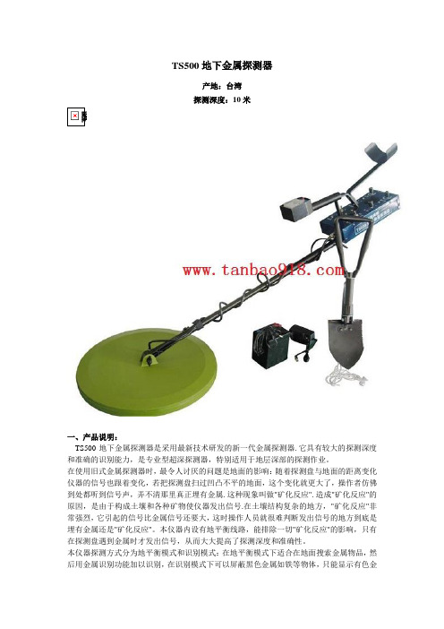
TS500地下金属探测器产地:台湾探测深度:10米一、产品说明:TS500地下金属探测器是采用最新技术研发的新一代金属探测器. 它具有较大的探测深度和准确的识别能力,是专业型超深探测器,特别适用于地层深部的探测作业。
在使用旧式金属探测器时,最令人讨厌的问题是地面的影响:随着探测盘与地面的距离变化仪器的信号也跟着变化,若把探测盘扫过凹凸不平的地面,这个变化就更大了,操作者仿佛到处都听到信号声,弄不清那里真正埋有金属. 这种现象叫做"矿化反应". 造成"矿化反应"的原因,是由于构成土壤和各种矿物使仪器发出信号.在土壤结构复杂的地方,"矿化反应"非常强烈,它引起的信号比金属信号还要大,这时操作人员就很难判断发出信号的地方到底是埋有金属还是"矿化反应"。
本仪器内设有地平衡线路,能排除一切"矿化反应"的影响,只有在探测盘遇到金属时才发出信号,从而大大提高了探测深度和准确性。
本仪器探测方式分为地平衡模式和识别模式:在地平衡模式下适合在地面搜索金属物品,然后用金属识别功能加以识别,在识别模式下可以屏蔽黑色金属如铁等物体,只能显示有色金属如黄金、银等物体。
另外它除了通过显示表头来区分金属类别外它还可以通过音调功能设置区分金属类别。
配备外置耳机接口,可接驳单声道耳机,简单易用;内置大容量可充电电池,有低电压指功能,配备充电器,充满电后可连续工作十小时以上。
配备专用兵工铲,方便野外作业。
二、特点:1、地平衡:能有效排除大地矿化反应,具有较佳的穿透能力。
TS500地下金属探测器对金、银、铁、锡……等一切金属都能探测,而对覆盖在这些金属之上的泥土、陶瓷、岩石、塑料、水泥、木材等物质都能穿透。
2、自动识别:可自动区分识别有色金属与黑色金属3、配有超大探盘设计,探测面积更宽,仪器探测灵敏,声音宏亮。
4、扬声器发声提示5、电池低电提示,电压表强度指示三、主要用途:1、探矿,可探各种金属矿物,且对某些高品位的矿,尤其对自然金块更为有效2、侦破搜查3、考古,发现埋藏在地下的金属文物和金银宝物4、检查地下管道、电线、电缆。
TS_MTS2019工具箱使用手册(一)

TSZ系列软件TS-MTS2019结构设计工具箱(v6.0)使用手册目录第一章总体说明 (1)1.1环境要求 (1)1.2帮助文档 (1)1.3主要功能 (1)1.4相关规范、规程、标准、标准图集及参考书 (3)1.5公共操作说明 (4)1.6版本主要功能表 (5)1.6.1各版本列表 (6)1.6.2界面说明 (6)1.7鉴定说明 (7)1.8技术支持 (7)第二章截面属性查询 (8)2.1基本截面 (8)2.1.1功能介绍 (8)2.1.2参数说明 (8)2.1.3计算原理 (10)2.2实腹、格构组合截面 (10)2.2.1功能介绍 (10)2.2.2参数说明 (11)2.3钢骨砼截面 (11)2.3.1功能介绍 (11)2.3.2参数说明 (11)2.4钢管砼截面 (12)2.4.1功能介绍 (12)2.4.2参数说明 (13)2.5钢管砼组合截面 (13)2.5.1功能介绍 (13)2.5.2参数说明 (13)2.5.3其他说明 (14)第三章钢节点设计 (15)3.1组织框架 (15)3.2功能介绍与参数页面组织 (17)3.2.1梁柱连接 (17)3.2.2梁梁连接 (23)3.2.3柱脚节点 (24)3.2.4柱柱连接 (26)3.2.5桁架/支撑连接 (27)3.2.6与混凝土连接 (27)3.2.7参数页面组织 (28)3.3标准参数页面介绍 (31)3.3.1基本参数 (31)3.3.2腹板连接参数 (40)3.3.3翼缘连接参数 (41)3.3.4端板参数 (43)3.3.5梁柱连接参数 (43)3.3.6梁梁连接参数 (44)3.3.7盖板连接参数 (45)3.3.8抗剪键参数 (45)3.3.9梁加劲肋设计参数 (45)3.3.10锚栓群参数 (46)3.3.11钢筋参数 (47)3.3.12栓钉群参数 (48)3.3.13预埋件连接参数 (48)3.3.14支座参数 (49)3.3.15柱边连接参数 (49)3.3.16附加参数 (50)3.3.17连接参数 (50)3.4零件计算 (51)3.4.1焊缝群计算 (51)3.4.2锚栓群计算 (52)3.4.3螺栓群计算 (53)3.4.4预埋件计算 (53)3.5计算原理 (53)3.5.1设计计算方法 (54)3.5.2基本连接计算 (55)3.5.3零件计算 (60)3.5.4节点抗震设计 (68)3.5.5等强内力 (78)3.5.6性能化设计 (79)第四章钢构件设计................................................................................................................ 错误!未定义书签。
面音 TS 系列放大器用户手册说明书

Audio Amplifiersfor Professional Applications.Face Audio Owner's Manualfor TS Series Amplifiers8675 South Sandy Parkway Building 110 Sandy, Utah 84070 Toll Free (877) 525-1163 OWNER’S MANUALThe information furnished in this manual does not include all of the details of design or variations of the equipment,nor does it cover every possible situation that may arise during installation,operation or maintenance.This manual will familiarize you with features of your amplifier so we suggest you take time to read through it before operating your system to get the most out of your amplifier.For your safety read the sections on important precautions,input,output and power connections.Keep this manual for future reference.Each Face Audio™amplifier is inspected before leaving the factory and should arrive damage-free.However,in the event damage did occur in transit notify the shipping company and point-of-purchase immediately.Be sure to save the carton and all packing material for any future shipping needs as they are specially designed to protect the amplifier during transit.SAFETY PRECAUTIONS Do’sKeep this owner’s manual for future reference. Take careful notice of all markings on the chassis.Take care not to block blower intake or exhaust ports. Always operate the amplifier with the ground wire intact.Ensure the amplifier is always powered by an electrical system with a ground.Before powering the amplifier verify the voltage of the power source matches its rated voltage.Avoid operating the amplifier on surfaces which may interfere with normal flow of air around it,suchas a carpeted floor,sofa,bed or other similar non-smooth surfaces.Don’tsDo not ground any red terminal.Do not operate the amplifier while standing in water. Do not spill water or other liquids into or on the amplifier.Do not use the amplifier if the electrical cord is frayed or broken.Do not use the unit near stoves,radiators or other heat generating devices. Do not EVER connect the output of the amplifier to any other voltage source. Do not run the output of any amplifier channel back into another input channel. Do not parallel or series connect an amplifier output with any other amplifier output.Do not drive the inputs with a voltage greater than that required to drive the amplifier to fulloutput.OPERATING PRECAUTIONSVoltage:Make sure the AC mains voltage is correct and is the same as that printed on the rear of the amplifier. Damage caused by using improper voltage is not covered by warranty. Be sure to use high quality power outlets and strips that can withstand the power requirements of the amplifier.Shock Hazard:Face Audio™ amplifiers produce hazardous output voltages. The actual current draw an amplifier demands depends on many factors such as load, output level and the crest factor of programmed material. The power requirement of Face Audio™ amplifiers is rated under typical usage conditions with both channels driven so that peaks are just at the clipping point (maximum current draw for each amplifier is listed in the specifications section). To avoid electrical shock please:Make sure the power switch is off before making any input or output connections and before plugging in the amplifier.Do not touch any exposed speaker wiring while the amplifier is operating.Do not remove the top cover of the amplifier as there are no user serviceable parts inside.Connectors & Cables:Always use high quality speaker cable of the correct gauge for the application and only use shielded MIC wire for the inputs. Poor cabling will be the root cause for most of the problems you encounter.Speaker/Driver Damage:Only appropriately rated speakers/drivers should be used with Face Audio™ amplifiers to avoid damage to speakers/drivers. Turning the gain controls all the way down before powering-up the amplifier is recommended to prevent speaker damage.Face Audio™ will not be responsible for damaged speakers. If you are unsure about the capacity of your speakers please consult your speaker manufacturer.Any harsh pops or cracking distortion may be an indication of the speaker voice coil striking the magnet assembly, if these symptoms should arise reduce power immediately. A single high-power crescendo can damage high-frequency drivers almost instantaneously while low-frequency drivers can usually withstand higher power levels for only a few seconds before they fail.Face Audio™ recommends using amplifiers of this power range to achieve cleaner sound rather than solely for increased volume.Interference:This device may cause interference when placed in close proximity to radio tuners andtelevision sets.Mounting:All Face Audio™ amplifiers will mount in a standard 19” rack, 4 front panel mounting holes are provided for this. Your amplifier uses a forced-air cooling system to maintain a low operating temperature. Air is drawn in through the front by a blower that is placed in the rear of the unit, do not cover the front or rear of the device as this may cause it to overheat. As the temperature inside the unit increases the blower kicks on automatically to cool it, if the temperature gets too high the amplifier will automatically shut down.SWITCHES/INDICATORS/CONTROLSMode Select Switch:The rear panel is equipped with a“mode select switch”which enables the user to switch between bridged, parallel and stereo modes.Do not operate the mode select switch while the amplifier is on.For more details please refer to the section on Bridge/Parallel/Stereo Operation.Signal Ground Lift Jumper:There is a jumper switch located on the rear panel which electrically connects the signal ground to the chassis/AC ground.When the jumper switch is moved to the“up”position the signal ground is lifted and completely isolated from the chassis/AC ground.Do not use the amplifier with the jumper in the“up”position if it and the signal source equipment are not on the same AC ground.In a properly designed system the amplifier should receive its ground from the line cord;whenever possible the signal source should share the same AC ground as the amplifier.Fault LED:The Fault LED is red and may be an indication of short circuit,open circuit,DC voltage or overheating.Clip LED:The Clip LED is orange and indicates clipping.It will light dimly at the onset of clipping and increase in brilliance as clipping becomes more severe.The LED will continue to illuminate until clipping ceases.If the LED’s are flashing quickly and intermittently,the channel is sitting at clip threshold,while a steady,bright glow means the amplifier is clip limiting,or reducing gain to prevent severely clipped waveforms from reaching the speakers. Signal LED:There are two blue signal LED’s per channel.When an LED’s corresponding channel produces an output signal of~4volts RMS or more the LED will illuminate.It is useful in determining whether a signal is being amplified by the amplifier.Active / Power LED:The Active LED is blue and illuminates when the power is turned on.Input attenuators:These are the knobs located on the front panel for controlling gain to their respective channels in stereo mode.In bridged mode only channel A’s knob controls gain while channel B’s does not function.1. Front panel channel LEDs: Fault, Clip, Signal & Active (power).2. Combination circuit breaker & power switch.3. Air intake grill.4. Channel attenuators (knobs)Output Connections:Speakers can be connected to the binding posts on the rear of the amplifier using banana plugs,spade lugs or bare wire.Consult a wire gauge chart to determine the suitable wire gauge and length for the required load of your particular set up.The red binding posts are for connecting to the positive poles of the speaker and are considered “hot”,these connections should only be made after the amplifier has been powered off.The black posts are at signal ground and for connecting to the negative poles of the speaker.Never connect a hot output to a ground or another hot output!Always turn off the amplifier before makingconnections!MAKING CONNECTIONSInput Connections:Face Audio™amplifiers come with built-in phono jacks and/or XLR3F inputs,depending on the model.Phono Connectors:The amplifier’s built-in ¼inch input phono connectors can be wired for balanced,unbalanced,floating or ground-referenced sources.The connectors have a standard tip ring sleeve (TRS)configuration.Sleeve is ground (gnd). Tip is positive (+).Ring is negative (-).Please refer to the image below:XLR3Connectors:The amplifier’s built-in XLR3connector pinout configuration is as follows:Pin 1is ground (gnd). Pin 2is positive (+).Pin 3is negative (-).Please refer to the image below:a Bridge Mode:Both amplifier channels can be bridged together to make a very powerful single channel monaural amplifier.When the mode switch is set to the “bridge”position the built in power amplifiers operate in “push-pull”mode.The doubled output voltage from channel A and B appears on the positive (red)terminals on both channels.In Bridge mode the phases of channels A &B are 180degrees out of phase,so you do not use the individual output connectors.Follow the steps below to use this mode properly and e extreme caution when operating the amplifier in bridged mode.BRIDGE/PARALLEL/STEREO OPERATIONParallel Mode:While the mode selector switch is in the parallel position the input connectors for both channels are wiredPROTECTION FEATURESGeneral Protection:Each Face Audio™ amplifier incorporates special circuitry to protect the amplifier and attached speakers under most circumstances. Face Audio™ has tried to make the amplifier as fail-safe as possible by making it resistant to short and open circuits, DC voltage and overheating.When certain problems occur that cause a channel to enter Fault mode, the Fault mode LED for that channel will illuminate. Occurrences of DC voltage at output, excessive subsonic frequencies and thermal overloads will cause the channel’s output relay to disconnect the speaker load until the problem is corrected or the amplifier cools down.Thermal Protection:Face Audio™ amplifiers utilize a continuous variable speed blower to assist in cooling. The blower will change speed in response to the amplifier’s cooling needs. This way the amplifier maintains an internal temperature within the required range for continued operation under normal working conditions. If a channel’s heat-sink reaches 90C t he c hannel w ill d isconnect i ts l oad a nd t he F ault L ED w ill i lluminate. N ormal o peration w ill resume once the temperature cools down to 80C. Should this occur it may be an indication of obstructed airflow due to poor placement of the amplifier, a clogged air filter or excessive dust buildup on the inside of the unit.Short Circuit:A short circuit protection system safeguards the amplifier’s output transistors, in the event of short circuit or and other stressful loads the channel will protect itself by automatically disconnecting the load. In case of short circuit the Fault LED will illuminate, power-off the amplifier to reset it.DC Voltage Protection:If the amplifier detects DC voltage on a channel at its output, it will fault to protect the speakers. Should this happen the Fault LED will illuminate.Subsonic Frequencies:Face Audio™ amplifiers have a built-in subsonic frequency protection circuit for each channel which enables the amplifier to automatically disconnect the speakers when excessively high frequency energy occurs at the output.Power-on/Power-off Muting:The amplifier outputs are muted for approximately 4 seconds after power-on and immediately after power-off to prevent thumps or pops from being heard.Speaker Protection:All Face Audio™ amplifiers inherently protect speakers from DC voltages, subsonic signals and excessively high frequency signals. However, it is very important that users are aware of the application limits of their speakers and be sure that the amplifier does not exceed the speaker’s power capabilities. Face Audio™ will not be responsible for damaged speakers.Limiter:Face Audio™ amplifiers come with built in limiters to prevent inadvertent damage to it or equipment attached to it by less experienced users. It is highly recommended that the limiter never be disabled as you can damage the amplifier and other equipment if you push the amp too hard. If the limiter is disabled the amplifier will no longer be covered under warranty.MAINTENANCE&SERVICECleaning:Disconnect the amplifier from the AC main source before performing any type of cleaning.A damp cloth and mild non-abrasive cleaning solution may be used to clean the faceplate and chassis.Dust Removal:If operating in a dusty environment the heat sinks may clog with dust after prolonged use,this will interfere with cooling and may pose a fire pressed air should be used to blow the inside of the unit out.In extreme cases,such situations where the lid needs to be removed to free buildup,the amplifier should be referred to a qualified technician for a thorough cleaning.Do not remove the lid by yourself.Servicing:Servicing your amplifier requires a trained technician.There are no user serviceable components inside your unit and the danger of electrical shock exists if you remove the cover.Additionally,some of the components are exclusive to Face Audio™and require Face Audio™replacements.Technical Assistance:If you suspect your amplifier is faulty,first check your system configuration and amplifier settings to determine the origin of the problem is not incorrect audio interfacing,poor cabling or other system level problems.After the above variables have been eliminated as the root cause of the problem you should call Face Audio™for technical assistance at(801)501-0804.We have trained staff available on weekdays from9AM to5PM MST.Product Return Guidelines:In the event your Face Audio™product is defective please follow the guidelines below to return it to us for repair or replacement:1.Pack the product well for protection during shipping. It is preferable the unit be put back in itsoriginal packing.2.Include the following:a.A copy of the sales receipt.b.Your name.c.The return address.d.A phone number where you can be contacted.e.And a detailed description of the defect.3.Call the Face Audio™technical hotline and provide us with a tracking number for the package.4.Ship the product prepaid to the following address:Face Audio™,LLC8675 South sandy ParkwayBuilding 110Sandy, Utah 84070WARRANTYPlease refer to our website for the latest warranty information and product registration: .NOTES。
TS系列在线扭矩传感器快速入门指南说明书
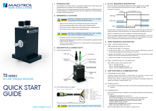
TS SERIESIN-LINE TORQUE SENSORSQUICK START GUIDE1. INTRODUCTIONThe TS Series In-Line Torque Sensor is a generation of high-precision torque sensors withintegrated electronic processing circuitry, developed by Magtrol.This sensor uses a non-contact measurement technology, integrates a conditioning electronic module providing a 0 to ±10 VDC torque output and 3 TTL signals (Tach A, Tach B and Index), for speed and angle measurement.2. WARNINGS & CAUTIONSINDICATES A HAZARDOUS SITUATION THAT , IF NOT AVOIDED, COULD RESULT IN DEATH OR SERIOUS INJURY .▪Make sure that all rotating parts are equipped with appropriate safety guards. ▪Always wear protective glasses when working close to rotating elements.▪Never wear a necktie or baggy clothes when standing close to rotating elements. ▪Never stand too close or bend over the rotating drive chain.INDICATES A HAZARDOUS SITUATION THAT , IF NOT AVOIDED, COULD RESULT IN MINOR OR MODERATE INJURY .▪Periodically check all connections and attachments.▪Make sure that all Magtrol electronic products are earth-grounded, to guarantee personal safety and proper operation. ▪Check the power supply voltage from 12 to 32 VDC (24 VDC recommended ) before operating the torque sensor.3. DESCRIPTION & CONNECTIVITY3.1 PARTS DESIGNATION3.2 ATTACHED ANALOG CABLECABLE SHIELD MUST BE CONNECTED TO GND AT USER’S SIDE.WARNINGCAUTION5. Analog cable4. Analog connector 2. Rotating shaft LOADENCODER SIDE1. Rotating shaft DRIVE7. USB cable6. USB mini-B8. HousingM12 x 1 / 8 Poles / Straight connector Pigtail wires1 White T ach B2 Brown T ach A3 Green Index (1 pulse / rev)4 Yellow BITE / TARE5 Grey T orque Ground 0V6 PinkT orque Signal ±5 (±10) VDC 7 Blue Ground GND 8 Red Power supply 12-32 VDCCase / Shield CAUTION 4. B.I.T.E. SEQUENCE DESCRIPTIONThe B.I.T.E. (Built-In Test Equipment) takes place at either «System Power Up» OR B.I.T.E. 8-pole (external line when pulled low for at least 1 s) OR B.I.T.E. USB.Its sequence is as follow:The stator will turn ON power to the rotor. The first 5.5 s of information will be used for rotor voltage measurement. Note during this time, the «analog output» and USB are set to zero. After 5.5 s, the signal from the rotor is available to the analog output and USB.The B.I.T.E. signal is available on both the analog voltage output and USB in N·m. The B.I.T.E. level is about 60 % of rated torque (RT). It is in addition to the torque applied to the sensor. One B.I.T.E sequence is usually performed when no torque is applied.5. TARE SEQUENCE DESCRIPTION5.1 TARE - STATUS DESCRIPTIONTARE (external line) is pulled up to + 24 V line 1. Activate and hold TARE < 1.0 s then ignore2. Activate and hold TARE > 1.0 s -3.0 s then the value is stored in RAM memory which will be reset to factory offset the next time the power is turned on 3. Activate and hold TARE > 3.0 s - 6.0 s then the value is stored in the NVM (Non-volatile Memory), then it will be saved when the power is turned off4. Activate and hold TARE > 6.0 s then the value in NVM is RESET5.2 TARE - DESCRIPTION OF LED BEHAVIORWhen TARE is pressed, all three LEDs turn OFF . ▪After 1 s, YELLOW turns ON .▪After 4 s, YELLOW and GREEN turn ON .▪After 6 s, YELLOW , GREEN and RED turn ON .6. USB FEATURES & COMMUNICATION6.1 HARDWARE & SOFTWAREA galvanic isolated USB interface is implemented. The maximum «common mode voltage»allowed between the sensor case and the computer GND is 33 V.TS Series Torque Sensor is delivered with software allowing communication between the sensor and a computer running Windows™ OS.6.2 POWER SUPPLYThe device is not powered by the USB. The sensor has to be powered through the 8-pole connector.6.3 COMMAND SETA set of commands are used for Configuration, Communication and System Function purposes. For instance:▪Configuration commands allow selection of:the FILTER cutoff frequency (2 / 5 / 10 / 20 / 50 / 100 / 1 000 Hz), the output power unit (hp, W, kW), the SPEED measurement algorithm (ΔT; Gated; Index) ▪Communication commands allow selection of measured values: TORQUE, SPEED, ANGLE, POWER▪System function commands allow activation of a sensor function: TARE, SAVE TARE, RESET TARE, B.I.T.E.Refer to the User Manual to get the complete “command set” list.For furter information, please read the product datasheet or the user manual. Both are available to download on our website © 2019 MAGTROL | Due to continual product development, Magtrol reserves the right to modify specifications without forewarning.MAGTROL INC70 Gardenville Parkway | Buffalo NY 14224 | USAp hone +1 716 668 5555 | e-mail *******************MAGTROL SARoute de Montena 77 | 1728 Rossens | Switzerland p hone +41 26 407 30 00 | e-mail******************T S S E R I E S - Q u I c k S T a R T g u I d E - 04 / 20197.a) Corresponds to < 0.05 % of RT peak to peak over the entire 1 kHz bandwidth b) For TS 100 (0.05 N·m) this parameter is degraded by a factor of 2.Applicable to both Analog and USB outputc) For TS 100 (0.05 Nm) and TS 101 (0.1 Nm) this parameter is degraded by a factor of 2d) Torque Output change due to power supply change e) PPR means Pulse Per Revolution f)Constant speed and based on the last 360 pulsesSTART ING & STOPPING CONDITIONS: Ensure that the torque applied to the sensor never exceeds the product specifications when the system is started and/or stopped.9. LED OVERVIEW OF DEVICE STATUSA color code is given by the activation of 3 LED lights (Yellow, Green, Red) located on the top of the sensor. This color code continuously communicates the operating status of the sensor, such as measuring status, tare functions, offset value, B.I.T .E. (Built-In T est Equipment) and overload.RED LED YELLOW LED GREEN LED 10. MAINTENANCEMagtrol TS Series In-Line Torque Sensors are virtually maintenance-free. This is mainly due to the quality of its components and its design (non-contact signal transmission).However, it may be necessary to change the bearings after extended use. The theorical lifetime of the bearings is 5 000 hours and Magtrol recommends replacing the bearings after this time.The user must not attempt to change or repair the bearings or any other components himself. For all maintenance or repair operations, please return the sensor to Magtrol. Failure to comply may result in serious damage to the transducer or may invalidate the warranty.11. CALIBRATIONTo ensure correct operation of the sensor and long-term measurement consistency, it is recommended to calibrate the sensor regularly. Magtrol recommends a factory calibration (e.g. in Magtrol’s ISO 17025 accredited laboratory) every 12 months .Returning the sensor directly to the Magtrol factory is both advantageous and economical. We can guarantee a dedicated calibration for the sensor performed by one of our best specialists. In addition, any wear and tear requiring maintenance will be immediately taken care of by our after-sales service team.12. PACKAGINGThe sensor is delivered with packaging designed to store the sensor while not in use as well as to return the sensor to Magtrol for annual calibration. Please, keep the packaging !8. INSTALLATIONMagtrol’s TS Series In-Line Torque Sensors should be considered primarily as precision measuring instruments and not as torque transmission components. The model of the sensor and the accuracy of its drive train alignment strongly influence the measurement accuracy and lifetime of the sensor, especially of the bearings.IT IS CRITICAL TO USE A COUPLING DESIGNED FOR Y O U R A S S E M B LY (e.g. F L E X I B L E C O U P L I N G S ). NEVER MAKE A RIGID ASSEMBLY !Magtrol provides a wide range of couplings suitable for torque measurement applications and can assist you in choosing the right coupling for your transducer. Please contact our technical service.There are two main ways to mount the TS torque sensor: supported or suspended (for low 8.3 INSTALLATION PRECAUTIONSALIGNMENT : Be careful to install with an accuracy equal to or less than the following permissible installation errors.WARNING。
安装短路电流等级-500 500f 509型接触器和起动器说明书
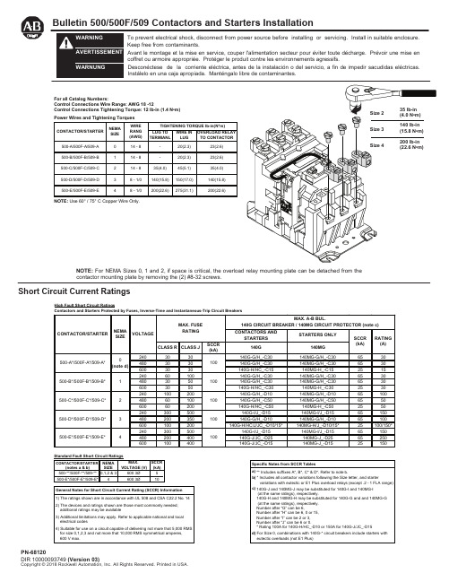
Bulletin 500/500F/509 Contactors and Starters InstallationShort Circuit Current RatingsTo prevent electrical shock, disconnect from power source before installing or servicing. Install in suitable enclosure. Keep free from contaminants.Avant le montage et la mise en service, couper l'alimentation secteur pour éviter toute décharge. Prévoir une mise encoffret ou armoire appropriée. Protéger le produit contre les environnements agressifs.Desconéctese de la corriente eléctrica, antes de la instalación o del servicio, a fin de impedir sacudidas eléctricas. Instálelo en una caja apropiada. Manténgalo libre de contaminantes.NOTE: For NEMA Sizes 0, 1 and 2, if space is critical, the overload relay mounting plate can be detached from the contactor mounting plate by removing the (2) #8-32 screws.High Fault Short Circuit RatingsFor all Catalog Numbers:Control Connections Wire Range: AWG 18 -12Control Connections Tightening Torque: 12 lb-in (1.4 N •m) NOTE: Use 60° / 75° C Copper Wire Only.Renewal Parts and Accessory KitsRenewal Contact Kit for Power Poles (One Pole Per Part No.)Size 0 ……………………………………………………….................................................Part No. 40410-331-51Size 1 ……………………………………………………….................................................Part No. 40410-331-52Size 2 ……………………………………………………….................................................Part No. 40420-322-51Size 3 ……………………………………………………….................................................Part No. 40430-300-51Size 4………………………………………………………..................................................Part No. 40440-300-51 Operating Coil…………...........................................................................................(Specify number and rating on coil label) Auxiliary ContactsSingle circuit (1 N.O.)……………………………………………………...…….........................Catalog No. 595-ASingle circuit (1 N.C.)………………………………………………...…….…….........................Catalog No. 595-BSingle circuit (1 N.C. Late Break) ………………..………………...……...............................Catalog No. 595-BLDouble circuit (2 N.O.)……………………………………………..…...……...........................Catalog No. 595-AADouble circuit (2 N.C.)……………………………………………..…………..........................Catalog No. 595-BBDouble circuit (1 N.O.-1 N.C.)……………………………………….....……….......................Catalog No. 595-AB Power Pole Adder KitSizes 0 and 1…………………………………………………………………..……...............Catalog No. 599-P01ASize 2………………………………………………………………………..….........................Catalog No. 599-P2ASize 3……………………………………………………………………........……...................Catalog No. 599-P3ASize 4……………………………………………………………………....………....................Catalog No. 599-P4ANOTE: Contactor sizes 0, 1 and 2 with 50 Hz coils and all size 3 and 4 contactors require a special coil(coil number ending with the letter “C”) whenever one or two power poles are added.Control Circuit Fusing KitSingle Pole, Rejection Fuse Only………………………………........................................Catalog No. 599-FR04NOTE: When contactor-mounted, each kit occupies the space of one double circuit auxiliary.Surge Suppressor12-120 Volt AC ...............………………………………………………....……..….................Catalog No. 599-K04240 Volt AC ................………………………………………..………..…….........................Catalog No. 599-KA04 Tie Point TerminalSizes 0, 1 and 2.....………………………………………………...……..….…....................Catalog No. 599-TP02Sizes 3 and 4……...……………………………………………...…………..….…................Catalog No. 599-TP34 Control Terminal KitSizes 0, 1 and 2 ..…………………………………………………...……..….…...................Catalog No. 599-CT02Size 3 .............……...……………………………………………...…………..….…...............Catalog No. 599-CT3Size 4 ............................................................................................................................. Catalog No. 599-CT4 Load Terminal Shield for Top Wired ContactorSizes 0, 1 and 2………………………………………………………………………………...Catalog No. 599-TS02Sizes 3 and 4..………………………………………………………………………...............Catalog No. 599-TS34 Top Wiring Terminal Kit (3 terminals)Sizes 0 and 1 ……………………………………………………….……..……….….........Catalog No. 599-TW01Size 2………………………………………………………………….…..……..…..................Catalog No. 599-TW2Size 3………………………………………………………………….……………..................Catalog No. 599-TW3Size 4………………………………………………………………….……....……..................Catalog No. 599-TW4 Timer Attachment KitLeft Hand On Delay……………………………………………...……....…….......................Catalog No. 596-TL32Left Hand Off Delay…………………………………………………..…...….........................Catalog No. 596-TL33Right Hand On Delay……………………………………………..……...….........................Catalog No. 596-TR32Right Hand Off Delay…………………………………………..……...................................Catalog No. 596-TR33NOTE: For size 2 contactors a special coil (coil number ending with the letter “C”) is required with any timer.When ordering specify catalog number and series letter on the device.Note: additional control circuit overcurrent protection may be required. refer to the National Electrical Code.The current rating of the control circuit conductors furnished with this device is 15 amperes for sizes 0 through 3 and 20 amperes for size 4.Maintain this equipment in accordance with guidelines of NFPA-70b, Electrical Equipment Maintenance.。
罗技Ts5O0使用说明书
罗技Ts5O0使用说明书
罗技TS500本体大小为115.5X71.2X57.5mm,也就手掌大小。
重量仅为230g,电池内置。
频率为80Hz~16kHz,对应Bluetooth 格式有A2DP/AVRCP/HFP/HSP。
前面是单元,背面有充电用USB借口以及音频接口开关。
上面有触摸屏,用于控制播放。
当然用手机等设备直接操作也是可以的。
从整体而言,TS500的外形活像一个小馒头。
TS500是一款无线蓝牙扬声器,使用iPhone连接,打开蓝牙后选择Mini Boom box就好。
TS500连接设备的速度极快,仅需1秒钟。
从现场视听来看,TS500扬声器虽小,但低音量感十足,作为使用电池的便携式音箱来说可谓上乘,很有魄力。
不过比起解析度,这款扬声器更重视力度一点,比较适合播放休闲音乐。
TS500的充电需要4小时,充满后可连续工作10小时。
USB直接充电也十分便利,颜色有红色,黑色,白色三种可供选择。
ts500-r2全站仪操作流程
ts500-r2全站仪操作流程TS500-R2全站仪操作流程一、引言TS500-R2全站仪是一种高精度的测量仪器,广泛应用于土木工程、建筑工程等领域。
本文将详细介绍TS500-R2全站仪的操作流程。
二、准备工作在开始操作全站仪之前,需要进行一些准备工作。
首先,确保全站仪的电池充电充足,并检查各部件的连接是否牢固。
其次,调整全站仪的设置,包括语言、单位、坐标系统等。
最后,选择合适的测量点,清理周围的障碍物,以确保测量的准确性。
三、开机与标定将全站仪放置在稳固的三脚架上,按下电源开关,等待全站仪启动。
启动后,系统会进行自检,确保各部件正常工作。
然后,进行标定操作,校准全站仪的水平和垂直仪器轴线。
四、测量与记录1. 建立基准点:使用全站仪的测距功能,测量已知点与待测点之间的距离,并记录下来。
基准点的建立是后续测量的基础。
2. 设置测量模式:根据实际需求,选择测量模式,包括角度测量、距离测量、坐标测量等。
在设置过程中,需要根据具体情况调整测量参数。
3. 进行测量操作:使用全站仪的望远镜对准待测点,观察准星,确定目标点。
然后,通过触摸屏或键盘输入相关指令,进行距离测量和角度测量。
全站仪会自动计算出目标点的坐标信息。
4. 记录测量结果:将测量结果记录在测量表格或电脑软件中,包括测量点的坐标、角度、距离等信息。
同时,可以进行数据的导出和备份。
五、数据处理与分析在测量完成后,可以将测量数据导入电脑软件中进行处理和分析。
通过数据处理,可以得到更精确的测量结果,并进行图形展示、计算分析等操作。
同时,可以与其他测量数据进行对比,检查测量的准确性。
六、测量结束与关机在测量结束后,及时关闭全站仪,避免电池过度消耗。
在关机前,需要进行数据的导出和备份,以防止数据丢失。
同时,还需要对全站仪进行清洁和保养,确保下次使用时的正常工作。
七、注意事项1. 在操作全站仪时,需要注意安全,避免对自己和他人造成伤害。
2. 在测量过程中,要保持仪器的稳定,避免外力干扰。
- 1、下载文档前请自行甄别文档内容的完整性,平台不提供额外的编辑、内容补充、找答案等附加服务。
- 2、"仅部分预览"的文档,不可在线预览部分如存在完整性等问题,可反馈申请退款(可完整预览的文档不适用该条件!)。
- 3、如文档侵犯您的权益,请联系客服反馈,我们会尽快为您处理(人工客服工作时间:9:00-18:30)。
二、技术参数
三、控制面板
1、显示屏:模式以及速度显示屏。
2、显示屏:印刷次数显示屏。
3、清零:在任何状态下按此键,计数器清零复位。
4、半/全自动:运行模式键:1)半自动模式(即单次运行)下,每按一下“启动/停止”键,机器运行一周后停止运行;全自动模式下,按“启动/停止”键,机器不停地运行,在此模式可通过“速度”键调节印刷速度。
5、印刷次数:运行时按此键,刮刀开始在网版上返复刮两次,再按一次此键,刮刀将恢复到刮一次的模式。
6、吸气模式:开启吸气开关后,按此键,吸气工作台开始不间断吸气;如再按一次,吸气工作台将随网板的落下而吸气。
7、速度:在全自动运行模式下,可从0至9级由慢到快调节印刷速度。
8、气源:在停机状态下按此键,将关闭滑行头及印头部分的气源,以方便调机。
同时其它键将被锁死,再按此键即可退出调机状态。
9、运行模式:两种模式,1)按此键,印头部分按四方型运行;2)再按一下,印头部分按三角型运行。
10、试印:停机状态下,按一下,升降部分上下移动。
11、试位:停机状态下,按一下,印头部分左右移动。
12、启动/停:按此键,可启动/停止正在运行的动作。
13、电源开关:开启/关闭电源。
14、吸气开关:开启/关闭工作台吸气泵电源。
15、印头升降开关:开启/关闭印头部分升降气缸。
16、调压阀:调整印刮部分的气压,以适应不同工件的需要。
四、丝印机的安装、测试、使用
本机适宜于安装在环境清洁,空气流动量不大,无粉尘及温度保持在25度左右的厂房(温度越高油墨越容易挥发)。
1、准备机器摆放的空间,并预留足够位置作检查和维修。
在拆除运输用的木箱等包装时,请立即检查机器在运输中是否有损伤。
机器在运输中受到之任何损伤将不包括在保修范围内,如有发现,请即向运输公司报告或致电本公司查询。
2、开机前准备
1)电源:220V 50Hz;2)气源:压缩空气;3)管位:视工件具体形状而专门制作。
3.调节机身平衡
在机座的四个脚掌板上分布有平衡调节螺丝,调节时先将配有的脚掌圆饼对准螺丝放在地上,再将螺丝上的螺母旋松,然后将螺丝顺时针旋转,使螺丝压紧脚掌圆饼,再分别调节四颗螺丝的高度,直至机身保持在水平位置后,锁紧上面的螺母,防止松动。
4.调试气压
接上气喉,调整气压,一般机器正常工作约为5BAR,如发现气压表指数偏高时,可先将调压制推上,然后逆时针方向旋转至标准压力,反之,反向调整,调整后,再把调压制按下,锁定气压在标准范围内。
为了使机器正常运作,防止外来水份渗入本机安装的各种精密气动组件之中,须经常把过滤器胶杯内的水或污物排出,将过滤器的排水顶针(见图3)向上按多次即可排出污水。
图3
5、印刮和印刷头的调节
1) 印刮的调节
用
可
图
A .用调升降旋扭调节印刷头高低。
B .将滑行座固定螺丝放松,可将印刷头前后移动。
3)印刮的调节
A、印刮及回墨片的位置
圆面印刷时,胶刮一般采用尖刮,正向印刷,印刷时与印件轴心线对准:曲面/平面印刷时,胶刮一般采用平刮,反向印刷,印刷时与印件起始线对准,松开印头滑块左右行程限位板,调节印刷头至正确位置。
图5
6、工作台部分调节
1)安装管位
丝印前一般需制做一套管位模具,将管位粘附在平面板,以保证丝印时工件的稳定性。
如无管位,可试用“二点定位法”、“三点定位法”(即用胶水等把2个或3个物品粘在工作台上以便定位,该物品高度必须低于工件印刷面高度)。
印刷较重较厚的物品时,可直接将物品直接放置在平面板,如被印刷品为纸张类等的轻薄物品时,为防止物品随丝网一起飘起,开启工作台吸气功能,才能达到满意的丝印效果。
2)工作台调节
松开工作台侧边下面的手柄螺丝,再通过调节39、43等三个旋扭进行左右、前后的调节。
7.网臂的调试
1)印刷行程调节方法(见图6)
根据印刷件的图案印刷要求确定好所需的印刷行程,然后松开行程调节块固定螺丝,将行程调节块左右移动,使行程距离达到要求之尺寸,锁紧固定螺丝即可。
图6
3)网板的安装调试
松开“34网框锁紧旋扭”,将网板放入,并锁紧(注意检查网板不可松动)。
松开升降组件锁紧螺丝,旋转“25搪环”,上下移动升降台至合适的距离(即网板与被印件的空间距离约1-2mm),锁紧升降组件锁紧螺丝,同时调节网板的平衡,使网板与被印件保持相对的水平。
A、网板的高低位置调试:先松开50升降线条的锁紧螺丝,再调节48升降旋扭,完毕后锁紧螺丝即可。
B、网板的前后位置调试:松开63定位螺丝母,再调节54微调旋扭,即可。
或松开52网框固定旋扭,就可将网板前后移动。
8.各机械部件的运作测试
各机械部分的运作是否正常,对产品的印刷品质和机器的寿命都有影响,因此,在印刷工作之前,测试各部件的运作是一件重要事项。
<1>插上电源,并开启电源开关后,检查IC板检数器是否有显示,如果无显示,则本机不能启动,须检查电路部分及相关的进程开关。
<2>按控制面板“试位”键(见图三),检查网臂左右移动是否顺畅,有无异常响声发出。
<3>按控制面板“试印”键(见图三),检查工作台升降是否正常,高低位置是否需要调整。
<4>按“启动”键(见图三)或按脚制开关,开启自动印刷状态,看印头滑动和升降的速度节奏是否配合,运行过程中是否有异常响声发出。
当机器振动大,可通过调节各部分的缓冲或限流制(见图)来减少机器运行撞击的力度。
9、加入油墨,打版测试(双色以上图案需进行套色对位)
当以上步骤全部检查无误后,即可开始正常的印刷生产工作。
五、各关键部件的详细说明
序号零件名称序号零件名称序号零件名称
1 回墨片16 胶刮锁紧螺丝31 网框夹
2 回墨片架17 胶刮夹固定螺丝32 网框锁紧旋扭
3 回墨片架座18 胶刮夹33 网臂座
4 微调旋扭19 固定码仔34 网臂
5 斜度调节码20 锁紧螺丝35 手柄螺丝
6 印头座21 缓冲36 离网气缸
7 升降轴22 滑行轴37 前后微调旋扭
8 印头管位板23 升降搪环38 急停座板
9 微调旋扭24 滑行气缸39 急停开关
10 印头升降气缸25 行程限位锁紧螺丝40 吸气台面
11 印头前后锁紧螺丝26 T字槽41 左右微调旋扭
12 印头胶刮气缸27 升降气缸42 手柄罗丝
13 减震胶圈28 齿轮
14 下降限流阀29 皮带
15 上升限流阀30 微调旋扭
六、丝印注意事项
1、工作车间应尽量保持无尘状态,因为粉尘会严重影响丝印质量,
2、做好被印件在平面台的固定装置,使被印件既可以随意放入和取出,又达到精确定位的目的,故此要有一套安放被印件的合适夹具,由于被印件的外形各不相同,故夹具要随需要而确定及制造。
3、当印刷发生塞网时,应用稀释水或洗网水来清洗网板,严禁用天拿水去清洗,否则天拿水与网板中的胶腊发生化学反应,破坏丝印网板的图案。
4、注意所采用的胶刮,外型是否符合被印件的特性。
胶刮有平刮(方角)和尖刮二种,当被印件为平面或印刷较平较硬状态时,以采用平刮(方角)胶刮为宜,印出的效果较佳;当被印件为有弧度或凸凹面状态时,以采用尖刮胶刮为宜,印出的效果较佳。
5、根据印刷图案的要求,选择密度合适的网纱。
6、将所需用的油墨调和至适合印刷之用,如油墨过粘,一来缺乏活性,二来容易塞网,引致印刷困难,如果油墨过稀,会导致印出的图案或线条颜色不够深,线条容易起毛等缺陷,所以丝印油墨的调较切不可轻视。
而油墨种类繁多,一定要用与被印件的特性相符合的油墨,才可产生美好的印刷效果。
7、印刷时存放在网框内的油墨量不可过多或过少,否则容易发生渗网、塞网,印刷图案浓淡不均等缺陷。
七、保养与维护
1、每周必须给网臂滑行轴承及升降座加注润滑脂一次,使机器导向部件保持润滑。
2、压缩空气的水分要过滤干净,以免水分进入气缸而降低气缸使用寿命。
3、注意每班后,排掉水隔中的积水,
4、保持机身的洁净,经常清洗粘附在表面的油墨。
5、每次下班时,必须清洗掉网板、胶刮上的油墨,防止油墨凝固后造成塞网、坏网等。
