RequisitePro 使用手册
ThingsPro Proxy 用户手册说明书
ThingsPro Proxy User’s ManualVersion 4.0, March 2022/product© 2022 Moxa Inc. All rights reserved.ThingsPro Proxy User’s ManualThe software described in this manual is furnished under a license agreement and may be used only in accordancewith the terms of that agreement.Copyright Notice© 2022 Moxa Inc. All rights reserved.TrademarksThe MOXA logo is a registered trademark of Moxa Inc.All other trademarks or registered marks in this manual belong to their respective manufacturers.DisclaimerInformation in this document is subject to change without notice and does not represent a commitment on the part of Moxa.Moxa provides this document as is, without warranty of any kind, either expressed or implied, including, but not limited to, its particular purpose. Moxa reserves the right to make improvements and/or changes to this manual, or to the products and/or the programs described in this manual, at any time.Information provided in this manual is intended to be accurate and reliable. However, Moxa assumes no responsibility for its use, or for any infringements on the rights of third parties that may result from its use.This product might include unintentional technical or typographical errors. Changes are periodically made to the information herein to correct such errors, and these changes are incorporated into new editions of the publication.Technical Support Contact Information/supportMoxa AmericasToll-free: 1-888-669-2872 Tel: +1-714-528-6777 Fax: +1-714-528-6778Moxa China (Shanghai office) Toll-free: 800-820-5036Tel: +86-21-5258-9955 Fax: +86-21-5258-5505Moxa EuropeTel: +49-89-3 70 03 99-0 Fax: +49-89-3 70 03 99-99Moxa Asia-PacificTel: +886-2-8919-1230 Fax: +886-2-8919-1231Moxa IndiaTel: +91-80-4172-9088 Fax: +91-80-4132-1045Table of Contents1.Introduction................................................................................................................................. 1-12.Installation Guide ......................................................................................................................... 2-1Installing ThingsPro Proxy .............................................................................................................. 2-2 Prerequisites ......................................................................................................................... 2-2Installation ........................................................................................................................... 2-4 3.Configuring ThingsPro Proxy......................................................................................................... 3-1Configuring ThingsPro Proxy ........................................................................................................... 3-2 Creating a Provisioning Plan ..................................................................................................... 3-2Provisioning Devices ............................................................................................................... 3-9Checking for Updates............................................................................................................. 3-11 4.Known Issues and Limitations ...................................................................................................... 4-1Introduction ThingsPro Proxy (TPP) is a Windows-based provisioning tool for batch configuring Moxa IIoT gateways according to specific provisioning plans (hereinafter referred to as “plans”). The provisioning plans include details such as device configuration, cloud-enrollment information, and security settings. The ThingsPro Proxy plans allow field operators to quickly configure/enroll Moxa devices without requiring domain knowledge and without having to go through complex steps, thereby reducing the cost of operation. The device provisioning tasks can be linked to a plan for quick and effortless provisioning.ThingsPro Proxy can be download from the Moxa website and installed in a Windows 10 environment. Version 3.0 of this user's manual is based on ThingsPro Proxy v1.3.0.ThingsPro Proxy leverages the ThingsPro Edge software installed on Moxa devices to provision the devices. ThingsPro Proxy and ThingsPro Edge together provide your devices with an IIoT gateway solution that includes streamlined data transportation from the endpoint to the cloud. Therefore, to provision Moxa devices via ThingsPro Proxy, you will need to install ThingsPro Edge (TPE) on the devices.Installation GuideIn this chapter, we describe how to install the ThingsPro Proxy tool.The following topics are covered in this chapter:❒Installing ThingsPro ProxyPrerequisitesInstallationInstalling ThingsPro ProxyPrerequisites1.PC with Windows 10 OS and Google Chrome browser.✓W indows 10 version 1809 or later✓G oogle Chrome 86.0.4240.183 (64 bit) or later2.Enable the Link-local IPv6 address on the PC.To enable the Link-local IPv6 address, do the following:i.In the Windows Search box, enter view network connections and click Open.ii.Select the network adapter that will be used to discover Moxa devices, right-click the network adapter, and select Properties.iii.Select the Internet Protocol Version 6 (TCP/IPv6) option.NOTE Ensure that the service port 5001 (local host) is available for the ThingsPro Proxy web server.3.Click OK to apply the changes.InstallationTo install the ThingsPro Proxy App, do the following:1.Download and run the ThingsPro Proxy installation file ThingsProProxySetup-x.x.x-yyyymmdd.2.Click Next.3.Select the I accept the agreement option and click Next.4.Specify the folder to install ThingsPro Proxy in and click Next.5.Specify the folder to create the ThingsPro Proxy shortcut in and click Next.6.Click Install.NOTE A command line console window (Windows cmd) will open during the installation process. DO NOT close the cmd window.7.After the installation process is complete, click Finish.unch the ThingsPro Proxy App.A webpage with privacy-related warnings will open.ThingsPro Proxy UM Installation Guide9.Click Advanced.10.Click Proceed to localhost (unsafe).3 Configuring ThingsPro ProxyThis chapter describes how to create a provisioning plan in ThingsPro Proxy and provision devices using the plan.The following topics are covered in this chapter:❒Configuring ThingsPro ProxyCreating a Provisioning PlanProvisioning DevicesChecking for UpdatesConfiguring ThingsPro ProxyYou will require at least one provisioning plan in ThingsPro Proxy before you can provision devices. Creating a Provisioning PlanA wizard will guide you through the process of creating a provisioning plan, which includes softwareupgrade, configuration import, cloud enrollment, and security settings. You can also view the settingsbefore finalizing the plan.To create a provisioning plan, do the following:1.Click on the Create Provisioning Plan link.2.Select the target device model and click START.3.Specify the ThingsPro Edge (TPE) Installation settings and click NEXT.a.Enable/disable the TPE installation settings using the Add ThingsPro Edge installation settings toplan slider.b.Select a mode.i.Download over-the-air: Specify a version of ThingsPro Edge or select the latest version.ii.Upload from my local drive: Upload a ThingsPro Edge file that you want to install.4.Specify the software upgrade settings and click NEXT.A. Enable/disable software upgrade using the Add software upgrade pack to plan slider.B. If you have enabled software upgrade, choose a method to upgrade the software pack—Auto ormanual—and browse to the folder path or specify a cloud URL.5.To import a configuration file, enable the Add configuration settings to plan slider, browse to the file,and specify the associated Password. Click NEXT.6.(optional) In the Cloud Enrollment page, click Manage and select Edit to change the settings.To add more cloud services, click + Add another.A.Azure IoT Device/ Azure IoT EdgeEnter the Connection String and click VERIFY & SAVE.If you want to edit the Connection String, click EDIT.The Device ID is auto generated by using the serial number of the device and authenticated via a symmetric key.B.Azure DPSi.Enter the Connection String and click VERIFY & SAVE.If you want to edit the Connection String, click EDIT and enter the ID Scope.The Device ID is auto generated using the serial number of the device and authenticated via a symmetric key.ii.(optional) Select The provisioning device is an IoT Edge-capable device.iii.Select an Assign Policy.iv.Enter the name of the IoT Hubs.v.Select a Re-provisioning policy.vi.(optional) Customize the Initial Device Twin State.vii.Click NEXT.C.Moxa DLM Servicei.Select the service type Moxa DLM Service.ii.Enter an Email (account) and Password.iii.Select a project name to register devices.iv.Click NEXT.7.(optional) You can disable a provisioning service to prevent devices from being discovered or modify thecurrent password. Click NEXT to apply the changes.8.(optional) You can upload Linux command scripts and deploy them to targeted devices.The supported file formats include tar.gz, bash, binary, executables, and Python3 package.curl https://127.0.0.1:8443/api/v1/authThe password is used to encrypt the plan and then decrypt it before importing the plan.10.Click DOWNLOAD & FINISH to download the plan.The plan will be downloaded as a *.zip file.NOTE ThingsPro Proxy uses plans to provision devices. Plans can be stored in a secure location and used in the different workplaces where ThingsPro Proxy is installed.Provisioning DevicesThere are two ways to provision devices: Targeted Provisioning and On-air Provisioning.Targeted Provisioning You can specify a batch of devices for provisioning based on the device model, firmware version, ThingsPro Edge version, and communication interfaces.On-air Provisioning ThingsPro Proxy will automatically scan all compatible devices in LAN and batch deploy the configuration based on the specified plan.NOTE ThingsPro Proxy relies on the UDP port 40404 for scanning devices in the same network. Be sure to add UDP port 40404 to the firewall allowed list for proper device discovery.To provision devices, do the following:1.After you have created a provisioning plan, click on the Provisioning link.2.Choose the mode of provisioning: Targeted Provisioning or On-air ProvisioningDevices will be accessed using their default credentials (Account: admin; Password: admin@123).3.(optional) Edit the default credential to discover your devices.You can click EDIT in the Device Access section to change the default credentials so that the deviceswhose default credentials have been changed can be discovered.4.Select devices to discover or press SCAN to re-scan the LAN for devices.5.Click NEXT.6.Select the provisioning plan file.•New plan file: Select this option to browse to a file in a local computer.•Recent plan files: Choose from an existing plan and enter the associated password.7.Click UPLOAD.8.Click NEXT.9.Click APPLY.NOTE Before running the provisioning plan, ThingsPro Proxy will synchronize your server time on to the devices.Checking for UpdatesYou can configure ThingsPro Proxy to update automatically. To configure auto-update, do the following:1.Go to the About page.2.Click MANAGE and select Check for updates3.If a new version is available, the information will be presented. Click INSTALL to install the new versionas needed.4.(optional) Automatic check for updates is disabled by default. You can select the Edit update settingoption under MANAGE to enable this service.4 Known Issues and Limitations1.ThingsPro Proxy v1.x.x does not support running multiple plans simultaneously.2. A connection failed message is displayed if the Ethernet interfaces are not able to get an IP addressassigned after ThingsPro Edge is installed. The LAN1 interface of ThingsPro Edge is DHCP enabled by default and this error results in the ThingsPro Proxy not being able to access ThingsPro Edge.3.DO NOT insert SIM cards before the provisioning process is complete.4.ThingsPro Edge has about 15 minutes to provisioning a device after it is powered on.Before starting the provisioning process, ensure that the ThingsPro Proxy is ready and the devices are powered on.5.The time taken to install ThingsPro Edge (TPE) is subject to the capacity of the devices. For example, itmight take around 30 minutes to install TPE on a UC-8100A-ME-T Series device.6.If the TPP web GUI is disconnected for an extended period and does not reconnect, you can stop andrestart the service.Click on the Windows Start button and select the ThingsPro Proxy folder. Click Stop ThingsPro Proxy Service and then Start ThingsPro Proxy Service to relaunch the TPP service.7.Devices newly registered with AWS IoT Core sometimes require a reboot to be available.。
RequisitePro 使用手册

Rational RequisitePro 用户手册目录第一章: 介绍 (4)1.1欢迎来到R A TIONAL R EQUISITE P RO T UTORIAL (4)1.2读者 (4)1.3特征 (4)1.4模块是怎样组织的? (4)1.5练习怎样? (5)1.6我要按顺序阅读这些模块吗? (5)1.7链接怎样? (5)1.8完成本手册需要多长时间? (5)1.9下一章是什么? (5)第二章需求管理 (6)2.1什么是需求管理? (6)2.2需求管理为什么重要? (6)2.3项目失败的原因 (6)2.4管理需求时考虑的的问题 (6)2.5概要 (7)2.6下一章是什么? (7)第三章REQUISITEPRO介绍 (7)3.1R EQUISITE P RO组件视图 (7)3.2一个R EQUISITE P RO项目 (8)3.3使用项目模板 (9)3.3工具栏 (10)3.4与需求文档一起工作 (10)3.5组织和跟踪需求 (11)3.6练习 (13)3.7概述 (14)3.8下一章是什么? (14)第四章记录需求 (15)4.1文档模板 (15)4.2与文档一起工作 (16)4.3需求 (16)4.4练习 (17)4.5概述 (20)4.6下一章是什么? (20)第五章组织需求 (21)5.1需求类型 (21)5.2需求属性 (21)5.3视图 (22)5.4练习 (23)5.5概述 (24)5.6W HAT'S NEXT? (24)第6章跟踪需求 (25)6.1管理变更需求 (25)6.2可跟踪性 (25)6.3可疑的连接 (25)6.4层次 (26)6.5视图 (26)6.6查询(过滤和排序) (27)6.7练习 (27)6.8概述 (32)6.9下一章是什么 (32)第一章: 介绍1.1 欢迎来到Rational RequisitePro TutorialRational RequisitePro Tutorial是一个介绍RequisitePro和Rational需求管理工具的联机用户手册。
服恩亚软件产品集成指南说明书
SERENA®DIMENSIONS® RM 12.3.1 Integration Guide for Microsoft® Project Serena Proprietary and Confidential InformationCopyright © 2001–2015 Serena Software, Inc. All rights reserved.This document, as well as the software described in it, is furnished under license and may be used or copied only in accordance with the terms of such license. Except as permitted by such license, no part of this publication may be reproduced, photocopied, stored in a retrieval system, or transmitted, in any form or by any means, electronic, mechanical, recording, or otherwise, without the prior written permission of Serena. Any reproduction of such software product user documentation, regardless of whether the documentation is reproduced in whole or in part, must be accompanied by this copyright statement in its entirety, without modification.This document contains proprietary and confidential information, and no reproduction or dissemination of any information contained herein is allowed without the express permission of Serena Software.The content of this document is furnished for informational use only, is subject to change without notice, and should not be construed as a commitment by Serena. Serena assumes no responsibility or liability for any errors or inaccuracies that may appear in this document.TrademarksSerena, TeamTrack, StarTool, PVCS, Comparex, Dimensions, Prototype Composer, Mariner and ChangeMan are registered trademarks of Serena Software, Inc. The Serena logo, Version Manager and Mover are trademarks of Serena Software, Inc. All other products or company names are used for identification purposes only, and may be trademarks of their respective owners.U.S. Government RightsAny Software product acquired by Licensee under this Agreement for or on behalf of the U.S. Government, its agencies and instrumentalities is "commercial software" as defined by the FAR. Use, duplication, and disclosure by the U.S. Government is subject to the restrictions set forth in the license under which the Software was acquired. The manufacturer is Serena Software, Inc., 1850 Gateway Drive, 4th Floor, San Mateo California, 94404-4061.Publication date: October 2015Table of ContentsPreface . . . . . . . . . . . . . . . . . . . . . . . . . . . . . . . . . . 5Objective . . . . . . . . . . . . . . . . . . . . . . . . . . . . . . . . . . . . . . . . . . . . .5Audience. . . . . . . . . . . . . . . . . . . . . . . . . . . . . . . . . . . . . . . . . . . . . .5Manual Organization . . . . . . . . . . . . . . . . . . . . . . . . . . . . . . . . . . . . .5Related Documents . . . . . . . . . . . . . . . . . . . . . . . . . . . . . . . . . . . . . .6Contacting Serena Technical Support. . . . . . . . . . . . . . . . . . . . . . . . . .6Integrating Dimensions RM and Microsoft Project. . . . . . . 9Exporting Data from Microsoft Project . . . . . . . . . . . . . . . . . . . . . . . . .9Configuring a Schema in Dimensions RM . . . . . . . . . . . . . . . . . . . . . . .10Importing Data into Dimensions RM. . . . . . . . . . . . . . . . . . . . . . . . . . .13Importing Data from the CSV File with RM Browser. . . . . . . . . . . . .13Integration Guide for Microsoft® Project3Table of Contents4Serena® Dimensions® RM 12.3.1PrefaceThis document describes the Serena® Dimensions® RM integration with Microsoft®Office Project Professional.The instructions in this document outline how to import data from Microsoft Project intothe Dimensions RM database, update project data in Dimensions RM, and export the databack into Microsoft Project. These instructions assume that you are familiar with MicrosoftProject. If not, consult the documentation provided by Microsoft. These instructions alsoassume that you know how to manipulate Dimensions RM project information. If not,consult the Serena Dimensions RM User’s Guide and the Serena Dimensions RMAdministrator’s Guide.These instructions assume that both Microsoft Project and Dimensions RM are alreadyinstalled on your system. See the Serena Dimensions RM Installation Guide forinformation on installing Dimensions RM.The instructions in this document are provided by Serena Software, Inc. for illustrativepurposes only. The instructions have been verified only for Microsoft Office ProjectProfessional 2003 as made available to Serena. Other versions of Microsoft Project mayintegrate with Dimensions RM in a similar manner, or a different manner, or not at all.Serena makes no representations or warranties regarding Microsoft Project, that theinstructions are valid, or that the instructions are applicable to any other version ofMicrosoft Project.The instructions do not replace the documentation provided by Microsoft for MicrosoftProject. The documentation for Microsoft Project should be your primary source ofinformation regarding Microsoft Project.ObjectiveThe purpose of this book is to describe how to integrate Dimensions RM with MicrosoftProject.AudienceThis document is intended for members of project teams who use Dimensions RM tocreate, manage, and track requirements during the lifecycle of a project. Manual OrganizationThe single chapter in this document describes how to integrate Dimensions RM andMicrosoft Project.Integration Guide for Microsoft® Project56Serena ® Dimensions ® RM 12.3.1PrefaceRelated DocumentsContacting Serena Technical Supportintersolv provides technical support for all registered users of this product, including limited installation support for the first 30 days. If you need support after that time, contact intersolv Support at the following URL and follow the instructions:Language-specific technical support is available during local business hours. For all other hours, technical support is provided in English.You can use the intersolv Support Web page to:⏹Report problems and ask questions.⏹Obtain up-to-date technical support information, including that shared by ourcustomers via the Web, automatic e-mail notification, newsgroups, and regional user groups.⏹Access a knowledge base, which contains how-to information and allows you to search on keywords for technical bulletins.⏹Download updates and fix releases for your Serena products.TitleDescriptionSerena® Dimensions® RM User’s GuideGuide to creating, managing, and tracking requirements during the lifecycle of a project.Serena® Dimensions® RM Administrator’s Guide Guide to configuring, managing, and administering projects and users.Serena® Dimensions® RM Installation GuideGuide to installing Dimensions RM.Serena® Dimensions® RMCommand Line Parameters Quick ReferenceList of the parameters used to issue commands from the command line.Serena® Dimensions® RM Integration Guide for IBM® Rational® Software Modeler Guide to integrating Dimensions RM and Rational Software Modeler (RSM).Serena® Dimensions® RMIntegration Guide for HP Quality CenterGuide to integrating Dimensions RM and Quality Center .Serena® Dimensions® RM Integration Guide for Serena® TeamTrack®Guide to integrating Dimensions RM and TeamTrack.License and Copyright Information for Third-Party SoftwareIntegration Guide for Microsoft ® Project7License and Copyright Information for Third-Party SoftwareLicense and copyright information for third-party software included in this release can be found as part of the software download available at:/Download/Default.aspxPreface8Serena® Dimensions® RM 12.3.1Integration Guide for Microsoft ® Project9Integrating Dimensions RM and Microsoft ProjectIntegrating Serena® Dimensions ® RM and Microsoft® Project lets you show traceability between the schedule information in your project and the other data that is stored in Dimensions RM.The integration provides the following capabilities:⏹Tracing a particular task through its entire life cycle⏹Justifying a particular life cycle activity by showing its relationship to a currently scheduled task⏹Performing detailed schedule tracking and impact analysisThe integration includes the following steps:1"Exporting Data from Microsoft Project" on page 92"Configuring a Schema in Dimensions RM" on page 103"Importing Data into Dimensions RM" on page 13Exporting Data from Microsoft ProjectTo export data from Microsoft Project:1Start Microsoft Project and open an existing project that contains data that is ready to be transferred to Dimensions RM.2Select File > Save As . The Save As dialog opens.3Enter a file name in the File name list.4Select CSV (Comma delimited) in the Save as type list.5Click Save . The Export Wizard starts. Click Next .6Select New Map and click Next .7The Map Options screen opens. Do the following:⏹Under Select the types of data you want to export , select Tasks .⏹Under Text file options , select the Export includes headers check box.8Click Next. The Task Mapping screen opens.IMPORTANT! Before you can save to a CSV file, you may need to set an option to allow Microsoft Project to save to legacy file formats. To do this, select Tools | Options. Then, on the Security tab, select the Allow loading files with legacy or non default file formats option under Legacy Formats .10Serena ® Dimensions ® RM 12.3.1Integrating Dimensions RM and Microsoft Project9Map the items in the From: Microsoft Office Project Field column to thecorresponding items in the To: Text File Field column. These names are exported as the titles of the data columns on the first row of the CSV file.10Click Next . The End of Map Definition screen opens. 11Click Save Map .12In the Map Name field, enter a name for the map. 13Click Save .14Click Finish when you have finished mapping items. The exported data is saved in a CSV file.You can view the CSV file in any text editor , or in Microsoft® Excel.15Close Microsoft Project. If you are prompted to save changes to the project, click Yes .Configuring a Schema in Dimensions RMTo configure a schema in Dimensions RM:1In RM Manage, select an existing project or create a new project.2Select File > Define Project Schema . The Class Definition tool opens.3Add a Schedule class to the project.4Activate the Schedule class, if not already activated. To do so, perform the following steps:a Right-click an empty space in the schema diagram.b Select Add Class > Manage class types . The Manage Class Types dialog opens.c Select Schedule and then click OK .5Add relationships between the Schedule class and other pertinent classes. For example, you could create a relationship between the Schedule class and the Tests class. Relationships are intended to show the schedule requirements (cost,duration, task name, and resource) for the products the tasks are associated with.NOTE The mapping should include all columns in your Microsoft Project project, plusthe Unique ID item. IMPORTANT! You may need to set an option to allow Microsoft Project to save to legacy file formats. To do this, select Tools | Options. Then, on the Security tab, select the Allow loading files with legacy or non default file formats option under Legacy Formats .Configuring a Schema in Dimensions RM The following illustration shows a portion of the schema diagram that contains the Schedule class and its relationship to the Tests class.6Double-click the Schedule class in the schema diagram. The Definition of class dialog opens.7Add attributes to the Schedule class that correspond to the fields in the CSV file generated from Microsoft Project, and delete attributes that do not correspond toIntegrating Dimensions RM and Microsoft Projectfields in the CSV file. These are the attributes into which data will be mapped from fields in the CSV file.8Change the date format to match the Microsoft Project date format. To do so, perform the following steps:a In the Definition of class dialog, double-click the Start Date attribute.b Click the Date tab.c In the Display Format field, type DY MM/DD/YYYY .d Repeat this procedure for the Finish Date attribute, and for any other attributes that contain date data.9Edit the Schedule class attribute list to add an Alpha Numberic attribute (A1) with the name Unique ID, as well as any other attributes to store additional Microsoft Project data. The Unique ID field will store the Project Unique ID to allow for consistent data exchange with Mcirosoft Project.10Select File > Saveto save the project schema.NOTE Use alphanumeric (not numeric) attributes wherever a numeric value is to be stored. This prevents Dimensions RM from transforming numeric decimal values into mathematical equivalents that may not be recognized correctly by Microsoft Project during future transfers. An example of such an attribute is an Outline_Numberattribute with a value of 1.2.Importing Data into Dimensions RMImporting Data into Dimensions RMImporting Data from the CSV File with RM Browser To import data from the CSV file:1On the Home view, click the CSV Import button. The CSV Import dialog box appears.2In the File Name field, enter or browse to find the CSV file you want to import.3To create new requirements, select Create from the Import Mode list. You can also replace attributes in existing requirements with values from the CSV file. For more on import options for CSV files, see the Dimensions RM User’s Guide.4From the Field Separator list choose Comma .5To limit the range of rows to import, select From from the Rows to Be Imported option and enter the range. Otherwise, leave All selected to imported data from all rows in the file.6Select the File has header row option.7From the Log Level list you can choose the level of detail in the summary report that displays after you start the import. Choose Terse or Verbose .8Under the RM Mapping heading, you must enter criteria to define how data from the CSV file will be imported to Dimensions RM. When you use the Create Import mode, you must map columns from the CSV file to requirements attributes in RM. Data from the columns you select will be imported to the attributes you map the columns to, in the new requirements. First select the requirements class from the RM Class field. Then, select the column from the CSV Column List field and the corresponding attribute from the RM Attribute field. Click the right arrow button to add the mapped pair to the Mapped List field.9Click Importwhen you have completed the mapping.NOTE In the procedures in this section, all data will be imported into the same class. However , subsets of project data from the same CSV file can be imported into different Dimensions RM classes.Integrating Dimensions RM and Microsoft Project。
NuEclipse ICP工具说明书

ICP Tool Revision HistoryNuEclipseRevision HistoryThe information described in this document is the exclusive intellectual property ofNuvoton Technology Corporation and shall not be reproduced without permission from Nuvoton.Nuvoton is providing this document only for reference purposes of NuMicro ® microcontroller based systemdesign. Nuvoton assumes no responsibility for errors or omissions.All data and specifications are subject to change without notice.For additional information or questions, please contact: Nuvoton Technology Corporation .TABLE OF CONTENTS1REVISION HISTORY (3)2SUPPORTED MICROCONTROLLER (4)3RESOURCES (8)ICP Tool Revision HistoryICP Tool Revision History1 Revision History Version Release Date Description1.02.022 2023/03/21 • Added supported microcontroller:– Nuvoton M0 Family: M091 Series.– Nuvoton M7 Family: KM1M7C Series.1.02.021 2022/11/15 • Added supported microcontroller:– Nuvoton M0 Family: M0A23OC1ACU, M0A23EC1ACU, M029GGC0AE.– Nuvoton M23 Family: NUC1263 Series, M2354LJFCE.1.02.020 2022/06/24 • Added supported microcontroller:– NuMicro M4 Family: M467H3SJHAE, M467H3KJHAE, M467H3JJHAE, M460KGCAE, M460SGCAE, M460AGCAE, M460LGCAE, M460YGCAE.– NuMicro MA35 Family: MA35D16H8A7C and MA35D16H0A7C.1.02.019 2022/04/29 • Added supported microcontroller:– NuMicro MA35 Family: MA35D1 series.• Upgraded eclipse version from Mars to 2021 and supported 64bits OS only.1.01.019 2021/12/01 • Added supported microcontroller:– NuMicro M4 Family: M460, I94100 series.– NuMicro M7 Family: KM1M7A.1.01.018 2021/03/12 • Added supported microcontroller:– NuMicro M0 Family: M030G/M031G series.– NuMicro M23 Family: NUC1262 series.1.01.017 2020/09/30 • Added supported microcontroller:– NuMicro M0 Family: M030G, M071, M0A21 series.– NuMicro M23 Family: M251 series.– NuMicro M4 Family: M471 series.1.01.016 2020/03/06 • Added supported microcontroller:– NuMicro M0 Family: M031BT, NUC1311 series.– NuMicro M23 Family: M2354 series.– NuMicro M4 Family: M479 series.1.01.015 2019/08/09 • Added supported microcontroller:– NuMicro M0 Family: M031 series.– NuMicro M23 Family: M261 series.– NuMicro M4 Family: M480LD series.ICP Tool Revision History 2Supported MicrocontrollerProduct Line Series Part NumberNuMicro®M0 FamilyM0A21M0A21EB1AC, M0A21EC1AC, M0A21OB1AC, M0A21OC1AC,M0A23EC1AC, M0A23OC1AC, M0A23EC1ACU, M0A23OC1ACU M029G/M030G/M031GM029GGC0AE, M030GGD1AE, M030GGC1AE, M030GTC1AE,M030GTD1AE M030GGC0AE, M030GTC0AE, M031GGD2AE,M031GTD2AE, M031GGC2AE, M031GTC2AE, M031GGC1AE,M031GTC1AEM031M030FD2AE, M030LD2AE, M030TD2AE, M031BTYD2AN, M031BTYE3AN,M031EB0AE, M031EC1AE, M031FB0AE, M031FC1AE, M031KG6AE,M031KG8AE, M031KIAAE, M031LC2AE, M031LD2AE, M031LE3AE,M031LG6AE, M031LG8AE, M031SC2AE, M031SD2AE, M031SE3AE,M031SG6AE, M031SG8AE, M031SIAAE, M031TB0AE, M031TC1AE,M031TD2AE, M031TE3AE, M032EC1AE, M032FC1AE, M032KG6AE,M032KG8AE, M032KIAAE, M032LC2AE, M032LD2AE, M032LE3AE,M032LG6AE, M032LG8AE, M032SE3AE, M032SG6AE, M032SG8AE,M032SIAAE, M032TC1AE, M032TD2AEM071M071MC2AE, M071MD2AE, M071R1D3AE, M071R1E3AE, M071SD3AE,M071SE3AE, M071VG4AEM091M091TC2AE, M091TD2AE, M091YC2AE, M091YD2AEM051DNM0516LDN, M0516ZDN, M052LDN, M052ZDN, M054LDN, M054ZDN,M058LDN, M058ZDNM051DEM0515LDE, M0516LDE, M0516ZDE, M052LDE, M052ZDE, M054LDE,M054ZDE, M058LDE, M058MDE, M058ZDEM0518AE M0518LC2AE, M0518LD2AE, M0518SC2AE, M0518SD2AEM0519AE M0519LD3AE, M0519LE3AE, M0519SD3AE, M0519SE3AE, M0519VE3AEM0564M0564LE4AE, M0564LG4AE, M0564SE4AE, M0564SG4AE, M0564VG4AEM058SAN M058SFAN, M058SLAN, M058SSAN, M058SZANMINI51DEMINI51FDE, MINI51LDE, MINI51QDE, MINI51TDE, MINI51ZDE,MINI52FDE, MINI52LDE, MINI52QDE, MINI52TDE, MINI52ZDE,MINI54FDE, MINI54FHC, MINI54LDE, MINI54QDE, MINI54TDE,MINI54ZDEMINI55MINI55LDE, MINI55TDE, MINI55ZDEMINI57MINI57EDE, MINI57FDE, MINI57TDE, MINI57XDEMINI58MINI58FDE, MINI58LDE, MINI58QDE, MINI58TDE, MINI58ZDENano100ANNano100LC2AN, Nano100LD2AN, Nano100LD3AN, Nano100SC2AN,Nano100SD2AN, Nano100SD3AN, Nano100VD2AN, Nano100VD3AN,Nano100ZC2AN, Nano100ZD2AN, Nano100ZD3AN, Nano120LC2AN,Nano120LD2AN, Nano120LD3AN, Nano120SC2AN, Nano120SD2AN,Nano120SD3AN, Nano120VD2AN, Nano120VD3AN, Nano120ZC2AN,ICP Tool Revision History Nano120ZD2AN, Nano120ZD3AN, Nano130VD3ANNano100BN Nano100KC2BN, Nano100KD2BN, Nano100KD3BN, Nano100KE3BN,Nano100LC2BN, Nano100LD2BN, Nano100LD3BN, Nano100LE3BN,Nano100ND2BN, Nano100ND3BN, Nano100NE3BN, Nano100SC2BN,Nano100SD2BN, Nano100SD3BN, Nano100SE3BN, Nano100WE3BN,Nano110KC2BN, Nano110KD2BN, Nano110KD3BN, Nano110KE3BN,Nano110RC2BN, Nano110RD2BN, Nano110RD3BN, Nano110SC2BN,Nano110SD2BN, Nano110SD3BN, Nano110SE3BN, Nano120KC2BN,Nano120KD2BN, Nano120KD3BN, Nano120KE3BN, Nano120LC2BN,Nano120LD2BN, Nano120LD3BN, Nano120LE3BN, Nano120SC2BN,Nano120SD2BN, Nano120SD3BN, Nano120SE3BN, Nano130KC2BN,Nano130KD2BN, Nano130KD3BN, Nano130KE3BN, Nano130SC2BN,Nano130SD2BN, Nano130SD3BN, Nano130SE3BNNano103 Nano103SD3AE, Nano103LD3AE, Nano103ZD3AENano102/112AN Nano102LB1AN, Nano102LC2AN, Nano102SC2AN, Nano102ZB1AN,Nano102ZC2AN, Nano112LB1AN, Nano112LC2AN, Nano112RB1AN,Nano112RC2AN, Nano112SB1AN, Nano112SC2AN, Nano112VC2ANNUC029AN NUC029LAN, NUC029TANNUC029AE NUC029FAE, NUC029TAENUC029xDE NUC029LDE, NUC029SDENUC029xEE NUC029LEE, NUC029SEENUC029xGE NUC029KGE, NUC029LGE, NUC029SGENUC029ZAN NUC029ZANNUC130/140CN NUC130LC1CN, NUC130LD2CN, NUC130LE3CN, NUC130RC1CN,NUC130RD2CN, NUC130RE3CN, NUC130VE3CN, NUC140LC1CN,NUC140LD2CN, NUC140LE3CN, NUC140RC1CN, NUC140RD2CN,NUC140RE3CN, NUC140VE3CNNUC100/120DN NUC100LC1DN, NUC100LD1DN, NUC100LD2DN, NUC100LD3DN,NUC100LE3DN, NUC100RC1DN, NUC100RD1DN, NUC100RD2DN,NUC100RD3DN, NUC100RE3DN, NUC100VD2DN, NUC100VD3DN,NUC100VE3DE, NUC100VE3DN, NUC120LC1DN, NUC120LD1DN,NUC120LD2DE, NUC120LD2DN, NUC120LD3DN, NUC120LE3DN,NUC120RC1DN, NUC120RD1DN, NUC120RD2DN, NUC120RD3DN,NUC120RE3DN, NUC120VD2DN, NUC120VD3DN, NUC120VE3DN,NUC122LC1DN, NUC122LD2DN, NUC122SC1DN, NUC122SD2DN,NUC122ZC1DN, NUC122ZD2DNNUC121 NUC121SC2AE, NUC121LC2AE, NUC121ZC2AE, NUC125SC2AE,NUC125LC2AE, NUC125ZC2AENUC123AN NUC123LC2AN1, NUC123LD4AN0, NUC123SC2AN1, NUC123SD4AN0,NUC123ZC2AN1, NUC123ZD4AN0NUC123AE NUC123LC2AE1, NUC123LD4AE0, NUC123SC2AE1, NUC123SD4AE0,NUC123ZC2AE1, NUC123ZD4AE0ICP Tool Revision HistoryNUC126NUC126LE4AE, NUC126LG4AE, NUC126NE4AE, NUC126SE4AE,NUC126SG4AE, NUC126VG4AENUC1261NUC1261LG4AE, NUC1261LE4AE, NUC1261NE4AE, NUC1261SG4AE,NUC1261SE4AENUC131AENUC131LC2AE, NUC131LC2AEU, NUC131LD2AE, NUC131LD2AEU,NUC131SC2AE, NUC131SC2AEU, NUC131SD2AE, NUC131SD2AEU NUC1311NUC1311LC2AE, NUC1311LD2AENUC200/220ANNUC200LC2AN, NUC200LD2AN, NUC200LE3AN, NUC200SC2AN,NUC200SD2AN, NUC200SE3AN, NUC200VE3AN, NUC220LC2AN,NUC220LD2AN, NUC220LE3AN, NUC220SC2AN, NUC220SD2AN,NUC220SE3AN, NUC220VE3ANNUC230/240AENUC230LC2AE, NUC230LD2AE, NUC230LE3AE, NUC230SC2AE,NUC230SD2AE, NUC230SE3AE, NUC230VE3AE, NUC240LC2AE,NUC240LD2AE, NUC240LE3AE, NUC240SC2AE, NUC240SD2AE,NUC240SE3AE, NUC240VE3AENUC2201NUC2201LE3AE, NUC2201SE3AENuMicro®M23 FamilyM251M251EC2AE, M251FC2AE, M251KE3AE, M251KG6AE, M251LC2AE,M251LD2AE, M251LE3AE, M251LG6AE, M251SC2AE, M251SD2AE,M251SE3AE, M251SG6AE, M251ZC2AE, M251ZD2AE, M252EC2AE,M252FC2AE, M252KE3AE, M252KG6AE, M252LC2AE, M252LD2AE,M252LE3AE, M252LG6AE, M252SC2AE, M252SD2AE, M252SE3AE,M252SG6AE, M252ZC2AE, M252ZD2AE, M254KE3AE, M254SD3AE,M254SE3AE, M256KE3AE, M256SE3AE, M258KE3AE, M258SE3AE,M254SD2AE, M256MD2AE, M256SD2AE, M254MD2AE, M258KG6AE,M254KG6AE, M258SG6AE, M254SG6AEM253M253LD3AE, M253LE3AE, M253ZE3AEM261M261ZIAAE, M261SIAAE, M261KIAAE, M262ZIAAE, M262SIAAE,M262KIAAE, M263ZIAAE, M263SIAAE, M263KIAAEM2351M2351KIAAE, M2351SFSIAAP, M2351SIAAE, M2351ZIAAEM2354M2354KJFAE, M2354LJFAE, M2354SJFAE, M2354LJFCENUC1262NUC1262LE4AE, NUC1262NE4AE, NUC1262SE4AENUC1263NUC1263LD4AE, NUC1263ND4AE, NUC1263SD4AE, NUC1263ZD4AENDA102NDA102SD2, NDA102SE3NuMicro®M4 FamilyM451M451LC3AE, M451LD3AE, M451LE6AE, M451LG6AE, M451MLC3AE,M451MLD3AE, M451MLE6AE, M451MLG6AE, M451MSC3AE,M451MSD3AE M451RC3AE, M451RD3AE, M451RE6AE, M451RG6AE,M451VE6AE, M451VG6AE, M452LC3AE, M452LD3AE, M452LE6AE,M452LG6AE, M452RD3AE, M452RE6AE, M452RG6AE, M453LC3AE,M453LD3AE, M453LE6AE, M453LG6AE, M453RD3AE, M453RE6AE,M453RG6AE, M453VD3AE, M453VE6AE, M453VG6AE, M4TKVG6AE,M4TKVE6AE, M4TKRG6AE, M4TKRE6AE, M4TKLG6AE, M4TKLE6AEM4521M4521LD6AE, M4521LE6AE, M4521RD6AE, M4521RE6AE, M4521SD6AE, M4521SE6AEM460M467SJHAE, M467KJHAE, M467JJHAE, M467HJHAE, M467H3KJHAE, M467H3JJHAE, M467SJHAN, M467KJHAN, M467JJHAN, M467HJHAN, M467S2JHAE, M467K2JHAE, M467J2JHAE, M467H2JHAE, M463KGCAE, M463VGCAE, M463SGCAE, M463LGCAE, M463YGCAE, M460KGCAE, M460SGCAE, M460LGCAE, M460YGCAEM471M471KI8AE, M471MD6AE, M471R1D6AE, M471R1E6AE, M471SD6AE, M471SE6AE, M471VG7AE, M471VI8AE, M471CI8AEM479M479SG8AEE, M479LG8AEE, M479NG8AEEM480M481SIDAE, M481LIDAE, M481ZIDAE, M482KIDAE, M482SIDAE, M482LIDAE, M482ZIDAE, M483KIDAE, M483SIDAE, M485KIDAE, M485SIDAE, M485LIDAE, M487JIDAE, M487KIDAE, M487SIDAE, M487KMCANM480LD M481SGCAE, M481SE8AE, M481SGCAE2A, M481LGCAE, M481LE8AE, M481ZGCAE, M481ZE8AE, M482KGCAE, M482SGCAE, M482SE8AE, M482LGCAE, M482LE8AE, M482ZGCAE, M482ZE8AE, M483KGCAE, M483SGCAE, M483SE8AE, M483KGCAE2A, M483SGCAE2ANUC442/472AE NUC442JG8AE, NUC442JI8AE, NUC442KG8AE, NUC442KI8AE, NUC442RG8AE, NUC442RI8AE, NUC442VG8AE, NUC442VI8AE, NUC472HG8AE, NUC472HI8AE, NUC472JG8AE, NUC472JI8AE, NUC472KG8AE, NUC472KI8AE, NUC472VG8AE, NUC472VI8AENUC505NUC505YO13Y, NUC505DS13Y, NUC505DSA, NUC505DL13Y, NUC505DLA, NUC505YLA2Y, NUC505YLAKM1M4BF0KM1M4BF02KXW/E, KM1M4BF02GXY/G, KM1M4BF03KXW/E, KM1M4BF03GXY/G, KM1M4BF04KXW/E, KM1M4BF04GXY/G, KM1M4BF05KXW/E, KM1M4BF05GXY/GKM1M4BF5KM1M4BF52KXW/E, KM1M4BF52GXY/G, KM1M4BF53KXW/E, KM1M4BF53GXY/G, KM1M4BF54KXW/E, KM1M4BF54GXY/G, KM1M4BF55KXW/E, KM1M4BF55GXY/GARM® Cortex®-M7 MCUs KM1M7AF0KM1M7AF00N/M/K, KM1M7AF02N/M/KKM1M7AF5KM1M7AF50N/M/K, KM1M7AF52N/M/KKM1M7CFKM1M7CF03N/K, KM1M7CF04N/K, KM1M7CF05N/K, KM1M7CF06N/K,KM1M7CF13N/K, KM1M7CF14N/K, KM1M7CF15N/K, KM1M7CF16N/KNuMicro® A35 Family MA35D1MA35D16F787C, MA35D16H8A7C, MA35D16A887C, MA35D16H0A7C,MA35D16A087C, MA35D16F987CICP Tool Revision HistoryICP Tool Revision History 3ResourcesWebsite Details NuEclipse on https:///tool-and-software/ide-and-compiler/•Download the latest NuEclipse installation file.•View the NuEclipse revision history.NuTool on GitHubhttps:///OpenNuvoton/Nuvoton_Tools•Check the open source example code of NuEclipse for easierdevelopment.https:///OpenNuvoton/Nuvoton_Tools/blob/master/Latest_NuLink_Firmware/README.md•View the Nu-Link firmware revision history.Important NoticeUsing this software indicates your acceptance of the disclaimer hereunder: THIS SOFTWARE IS FOR YOUR REFERENCE ONLY AND PROVIDED "AS IS" AND ANY EXPRESS OR IMPLIED WARRANTIES, INCLUDING, BUT NOT LIMITED TO, THE IMPLIED WARRANTIES OF MERCHANTABILITY AND FITNESS FOR A PARTICULAR PURPOSE ARE DISCLAIMED. YOUR USING THIS SOFTWARE/FIRMWARE IS BASED ON YOUR OWN DISCRETION, IN NO EVENT SHALL THE COPYRIGHT OWNER OR PROVIDER BE LIABLE TO ANY DIRECT, INDIRECT, INCIDENTAL, SPECIAL, EXEMPLARY, OR CONSEQUENTIAL DAMAGES (INCLUDING, BUT NOT LIMITED TO, PROCUREMENT OF SUBSTITUTE GOODS OR SERVICES; LOSS OF USE, DATA, OR PROFITS; OR BUSINESS INTERRUPTION) HOWEVER CAUSED AND ON ANY THEORY OF LIABILITY, WHETHER IN CONTRACT, STRICT LIABILITY, OR TORT (INCLUDING NEGLIGENCE OR OTHERWISE) ARISING IN ANY WAY OUT OF THE USE OF THIS SOFTWARE, EVEN IF ADVISED OF THE POSSIBILITY OF SUCH DAMAGE.。
【项目管理知识】RequisitePro中需求管理的12个步骤
RequisitePro中需求管理的12个步骤(译自RoseEnterprise____中的RequisitePro4.5中的随机文档)需求管理是对变动的需求进行确定、组织和制作文档的过程。
本文将介绍RationalUnifiedProcess(RUP)中的有关于需求管理的基本概念,并展示如何使用RequisitePro来实行需求管理。
RequisitePro是很特别的产品,它集成了一个大家都很熟悉的环境:MicrosoftWord,以及一个数据库来提供强有力的十分容易使用的框架,你可以用它来对产品需求进行管理。
你要在需求文档中逐条标记你的需求,然后通过数据库对它们进行管理。
以此为基础,你的团队可以对同一个项目进行合作与联系,并进行不断的更新。
理解需求管理的步是建立一个通用的词汇表。
Rational把需求定义为:一种在建系统必须遵循的条件或功能。
需求管理应该是:可以对系统的需求进行引入、组织和文档化的一种系统化的方法与步骤,以及建立和维护开发团队和客户之间关于系统需求变更的确认的过程。
要注意的是目前的需求管理没有通用的办法。
以下的各步骤是作为一种起点来提供的。
在你的开发环境中,由于你不断经历着你的软件的反复叠代并为此不断工作,你需要不断地重新定义你的过程,并且要找出适合你开发需要的工作程序。
由于这是反复迭代的过程,所以你要在项目中经常经历以下的12个步骤。
Step1:分析问题并收集stakeholderneeds系统分析对总体任务负有责任。
所有的团队成员,包括核心的stakeholder,都要帮助系统分析员从客户那里收集stakeholderneeds。
可以使用以下方法:面谈交流问题调查表集体讨论与灵感收集讨论板原型这些和客户交互的结果可以很方便地记录到RequisitePro文档中去。
Step2:为RequisitePro工程创建一个概要说明一旦你的团队已经分析了问题,并且收集了足够的stakeholderneeds,下一步是在RequisitePro中对你的项目组织安排进行规划。
ISPSoft 使用手冊

ISPSoft 使用手册目录ISPSoft 使用手册 (1)1. 软件简介 (1)1.1. 简介及系统需求 (1)1.2. 系统安装及设定 (2)1.3. 解除安装ISPSoft (4)1.4. 执行程序 (4)1.5. 初始设定 (6)2. 功能工具列简介 (9)2.1. 功能列 (9)2.2. 档案选项 (10)2.3. 编辑选项 (12)2.4. 视图选项 (16)2.5. 编译选项 (19)2.6. PLC主机选项 (19)2.7. 工具选项 (22)2.8. 窗口选项 (24)2.9. 说明选项 (25)3. 程序建立与打印 (26)3.1. 建立新檔 (26)3.2. 开启旧档 (26)3.3. 保存档案 (27)3.4. 另存新档 (28)3.5. 关闭项目 (29)3.6. 打印 (29)3.6.1. 梯形图打印 (29)3.6.2. 寄存器编辑(T、C、D) 打印、装置状态编辑(M、S) 打印 (31)3.6.3. 装置批注打印 (31)3.6.4. 档案寄存器编辑打印 (32)4. ISPSoft程序编辑概念 (33)4.1. 简介 (33)4.2. POU (33)4.2.1. 何谓POU (33)4.2.2. POU的结构 (34)4.2.3. 新增功能块 (35)4.3. 工作 (38)4.3.1. 工作的类型 (38)4.3.2. 指派POU至工作项目 (39)5. 快速入门指南 (40)5.1. 工作区 (40)5.1.1. 专案 (40)5.1.2. 装置批注表 (41)5.1.3. 已使用的装置 (43)5.1.4. 停电保持区块 (44)5.1.5. 系统符号表 (45)5.1.6. 联机信息 (45)5.1.7. 通讯设定 (46)5.2. 符号宣告 (47)5.2.1. 如何宣告符号 (47)5.2.2. 符号名称的宣告原则 (51)5.2.3. 符号筛选 (51)5.2.4. 符号表编辑 (52)5.2.5. 汇出/汇入符号表 (52)5.2.6. 同时宣告数个符号 (54)5.3. 建立项目 (55)5.3.1. 建立新的项目 (55)5.3.2. 建立程序POU (56)5.4. 建立程序内容 (58)5.4.1. 建立符号 (58)5.4.2. 以阶梯图编辑输入及输出功能 (58)5.4.3. 检查POU并编译项目 (61)6. 梯形图编辑模式 (62)6.1. 梯形图编辑模式环境 (62)6.2. 基本操作 (62)6.2.1. 新增POU (62)6.2.2. 工作设定 (65)6.2.3. 编辑全域符号表 (67)6.2.4. 设定停电保持区块 (68)6.2.5. 系统符号表 (69)6.3. 编辑范例 (69)6.4. 编辑梯形图 (73)6.5. 符号表 (95)6.5.1. 局域符号表 (95)6.5.2. 在符号表中新增或修改符号 (96)6.5.3. 符号命名规则 (97)6.5.4. 符号编辑技巧 (97)7. 指令列表IL (100)7.1. IL概观 (100)简介 (100)7.1.1. IL7.1.2. IL结构 (100)7.2. 使用IL编辑 (100)7.2.1. 以IL新增POU (100)7.2.2. 开始编辑 (101)8. 顺序功能图编辑模式 (102)8.1. 顺序功能图简介 (102)8.2. 顺序功能图编辑模式环境 (102)8.2.1. 工作区 (102)8.2.2. 程序编辑区 (103)8.3. 建立顺序功能图程序 (103)8.3.1. 新增顺序功能图POU (103)8.3.2. 新增步进点与转换条件 (104)8.3.3. 新增分歧与合流 (105)8.3.4. 跳跃 (108)8.4. 新增动作 (109)8.5. 新增转换 (110)8.6. 指定动作与转换 (111)8.6.1. 指定动作 (111)8.6.2. 指定转换 (111)9. PLC主机 (113)9.1. 通讯 (113)9.2. 数据传输 (114)9.3. 系统安全设定 (116)9.3.1. 密码设定 (116)9.3.2. 程序上载失效 (117)9.3.3. 只读装置区域设置 (117)9.3.4. PLC识别码设定 (118)9.4. PLC运行⁄停止 (119)9.5. 在线模式 (120)9.6. 装置监控 (121)9.7. 装置设定ON/OFF (124)9.8. 装置强制锁住ON/OFF (126)9.9. 改变现在值 (127)9.10. 寄存器编辑(T、C、D) (129)9.11. 装置状态编辑(M、S) (131)9.12. 文件寄存器编辑 (134)9.13. PLC程序内存设定 (135)9.14. 在线编辑模式 (136)9.15. 传送变更后的程序 (136)9.16. 记忆卡通讯 (138)9.17. PLC状态信息 (139)9.18. 通讯侦测 (140)10. 工具 (142)10.1. 通讯设定 (142)10.2. PLC机种设定 (142)10.3. 程序设定 (143)10.3.1. 子程序密码设定 (143)10.3.2. 程序识别码设定 (144)10.3.3. 项目密码设置 (145)10.4. 万年历设定 (145)10.5. PLC 永久备份设定 (146)10.6. TC-01密码钥匙设定 (146)10.6.1. TC-01密码钥匙输入 (146)10.6.2. TC-01密码钥匙清除 (147)10.7. 清除MRU列表 (147)10.8. 导入⁄导出 (148)10.8.1. 导入符号表 (148)10.8.2. 导出符号表 (148)10.8.3. 导入程序单元 (149)10.8.4. 导出程序单元 (150)10.8.5. 导入功能块 (151)10.8.6. 导出功能块 (152)10.8.7. 导入使用者编辑格式 (153)10.8.8. 导出使用者编辑格式 (154)10.9. 语言选项 (154)10.10. 选项 (155)10.10.1. 初始化设定 (155)10.10.2. 项目管理区 (156)10.10.3. 编译讯息 (157)10.10.4. 符号表 (157)10.10.5. Ladder/FBD (158)10.10.6. SFC (159)10.10.7. IL (159)11. 仿真器 (160)11.1. 启动仿真器 (160)11.2. 仿真器功能图标 (161)11.3. 侦错模式 (162)12. 说明 (163)12.1. 关于 (163)12.2. 帮助 (163)13. 应用实例 (164)13.1. 交通号志变换 (164)13.2. 动作流程图 (165)13.3. 编程范例 (166)13.3.1. 建立SFC编程的POU (166)13.3.2. 建立符号表 (167)13.3.3. 建立转换条件(Transsitions) (168)13.3.4. 建立步序动作(Actions) (169)13.3.5. 绘制SFC (172)13.3.6. 指定转换条件(Transsitions) (172)13.3.7. 指定步序动作(Actions) (173)13.3.8. 建立触发POU (173)13.3.9. 程序编译(Compiler) (174)13.4. 动作模拟 (175)14. 附录 (176)14.1. 键盘对应功能与快捷键 (176)14.2. 工具列 (176)14.2.1. 文件工具列 (176)工具列 (176)14.2.2. PLC14.2.3. 标准编辑工具列 (177)14.2.4. 程序编辑工具列 (178)14.2.5. 除错工具列 (178)14.3. 菜单 (179)14.3.1. 档案 (179)14.3.2. 编辑 (179)14.3.3. 视图 (180)14.3.4. 编译 (181)14.3.5. PLC (181)14.3.6. 工具 (182)1. 软件简介11. 软件简介1.1. 简介及系统需求ISPSoft 为台达电子DVP 系列可程控器在Windows 操作系统环境下所使用的程序编辑软件。
使用Ratioanl_RequisitePro管理你的需求
使用Ratioanl RequisitePro管理你的需求关于这篇教程第1 页(共3 页)软件开发周期中经常被忽视的一个部分就是需求。
这些需求有很多种不同的形式,包括用户和管理层的请求,你的竞争对手产品的特性和功能,和被开发团队要求的实现特定需求的需要和需求。
如果你是一个项目经理或者软件产品的领导开发者,那么在整个项目的生命周期中,你可能被包括在需求的说明和管理中。
管理和比较需求信息是耗时的,除非你拥有象Ratioanl RequisitePro 这样的工具通过需求说明和管理的过程来帮助你。
RequisitePro 是一个能够使你在应用开始被开发之前指定一个应用的需求和特性的工具。
这可以通过在实际的编码过程之前给你的开发人员一个应用的最初定义,这样可以节省时间、金钱并减少大量的挫折。
RequisitePro 为存储和跟踪需求提供了一个数据库。
你能够通过一个专门的类似项目管理的界面添加需求到数据库中,或者当需求说明是用Microsoft Word 编写的,你可以将Word 文档中的需求项移到数据库中。
后面的方法能够使你继续使用你所熟悉的需求说明的文档和模板,并且甚至能够从Word 文档中产生需求,这样你可以从被管理的需求数据库中获得所有的利益。
在这篇教程中,你将看到需求过程的基本机制和RequisitePro 如何能够辅助说明和跟踪需求的过程。
各种需求内容被包含在下面的部分:∙计划一个软件项目∙将你的需求移到RequisitePro 中∙组织项目信息∙在RequisitePro 中创建需求∙项目文档∙报告和视图∙在一个项目期间管理需求开始一个项目第1 页(共7 页)让我们通过看看什么是一个真正的需求,它如何影响开发过程、项目计划的结果和这些信息如何能够被转换成为RequisitePro 工作的方式开始。
软件项目可以以很多不同的方式开始:来自于客户或者其他部门的一个正式请求、对你的工作有帮助的新软件部分的请求,一个已存在的系统被分成一系列更小的项目以使项目的处理更加简单。
IBM Rational RequisitePro学习手册
什么是RequisitePro
RequisitePro是一个需求管理工具,它帮助团队综合的管理项目需求并 使得合作和沟通更容易。RequisitePro由不同的工作区组成,但相关的 工作在这里完成。工作区从工具栏中开启。所有需求信息存储在数据库 里;视图工作区(View Workplace)提供访问那些信息的通道。 RequisitePro将Microsoft Word和数据库集成在一起,因此让你能够用 自然语言清晰的表达需求,并同时组织它们。你可以不费力的在Word和 数据库之间移动来组织需求,设定优先级,跟踪它们的关系,并跟踪需 求变化。
10
IBM Software Group | Rational software
RequisitePro视图
可以创建三种不同类型的视图: • 属性矩阵视图(Attribute Matrix View)显示所有指定类型的需求。需 属性矩阵视图( ) 求按行列出,它们的属性出现在栏里。这个视图帮助你组织和优化需求; 例如,你可以对需求做基于优先级(Priority)或危机(Risk)的排序。
6
IBM Software Group | Rational software
Create a New Project
1. Open Rational RequisitePro. The Open Project dialog box opens. Click the New tab. 2. Select the Use-Case Template icon. Note that when you select an icon, a description of that template appears in the text box at the bottom of the dialog box. Click the Details check box to toggle the display of the template description box. 3. Click OK. The Rational RequisitePro Project Properties dialog box opens. 4. In the Name box, type My Quick Tour Project. Filling in the Description box is optional. 5. Click OK. A dialog box opens, telling you that the project directory does not exist and asking you whether you want to create it. 6. Click Yes. A dialog box opens, informing you that your project has been created. 7. Click Close Now look at your project directory in the Explorer. It shows the project you created and several default packages. The packages contain document outlines and views to help get you started.
ICP DAS ET-87Pn-MTCP 产品快速入门指南说明书
Quick Start Guide forET-87Pn-MTCPMay 2014, Version 1.0.2Congratulations on purchasing ET-87Pn-MTCP - a Modbus TCP I/O expansion unit to expand I-87K series I/O modules and the most popular automation solution for remote monitoring and control application. This Quick Start Guide will provide informationneeded to get started. Please also consult the User Manual for detailed information on the setup and use of ET-87Pn-MTCP .In addition to this guide, the package includes the following items:ET-87Pn-MTCPSoftware Utility CDScrew Driver (ET-87P4-MTCP/ET-87P8-MTCP)(1C016)● ET-87Pn-MTCP Reference DocumentCD:\Napdos\Modbus\ET87Pn\Document\/pub/cd/8000cd/napdos/modbus/et87pn/document/● ET-87Pn-MTCP Website/root/product/solutions/pac/ipac/et-87pn-mtcp.html● ICP DAS Website/1Mounting the HardwareThe ET-87Pn-MTCP installation must provide proper ventilation, spacing, and groundingto ensure the equipment will operate as specified. A minimum clearance of 50mmbetween the ET-87Pn-MTCP and the top and bottom side of the enclosure panels mustbe provided.2Connecting to PC, Network and Setting up the Poweri. Connect PC to LAN1 port through a hub . The ET-87Pn-MTCP is equipped with RJ-45 Ethernet ports for connection to an Ethernet hub/switch and PC. You can also link directly the ET-87Pn to PC with an Ethernet cable.ii. Connect the +24 V DC power supply to PWR1 and GND terminals.3 Installing the Modbus UtilityThe Modbus Utility can be obtained from companion CD or ICP DAS FTP site:CD:\Napdos\Modbus\Modbus_Utility\ftp:///pub/cd/8000cd/napdos/modbus/modbus_utility/4Using the Modbus Utility to Assign a New IP AddressUDP Search of the Modbus Utility can be used to configure the IP address. Before starting the configuration process, ensure that the LAN1 are used to connect to network and make the controller under the running firmware mode . The default IP addresses are as follows:Item IP Address 192.168.255.1 Subnet Mask255.255.0.0Gateway192.168.0.1Step 1: Run the Modbus Utility, and then search the ET-87Pn-MTCP.i. Double-click the Modbus Utility shortcut on the desktop. ii. Select UDP Search from the Client Tools menu.iii. Click the Search Servers button of the eSearch Utility dialog, waiting for the search to be done.Step 2: Configure IP Address. i. Select the “Name” field from the default IP address row ofET-87Pn-MTCP . ii. Click the Configuration (UDP) button to open the setting dialog.iii. Configure the IP settings. iv. Click the OK button to save theconfiguration.5Inserting and Wiring the I/O ModulesThere are various types of I/O expansion modules for interfacing many different field devices to the ET-87Pn-MTCP .For more information about I/O expansion module, please refer to/products/PAC/xpac/remote_io_support_list.htmii. Click the Configuration (UDP) button.iv. Click the OK button.6Using the Modbus Utility to Configure the ModuleThe Modbus Utility can be used to make the communication between the ET-87Pn-MTCP and PC/Laptop via the Modbus/TCP protocol.Step 1: Run the Modbus Utility and connect to ET-87Pn-MTCP. i. Double-click the Modbus Utility shortcut on the desktop. ii. Click the Modbus/TCP button in the middle of the Select Controller dialog.iii. Enter the IP address, and then click the Connect button.Enter the IP address, and then click the Connect button.Step 2: Match the I/O module and then get the I/O configuration information. i. Click the Refresh button to match the I/O modules to configuration of the controller.ii. Select the About option from the Help menu to get the I/O configuration and firmware information.iii. Check the module status diagram, ensuring for the I/O modules to be matched.i. Click the Refresh button. iii. See the module status diagram, ensuring for the I/O modules to be matched.Step 3: Set I/O configuration, get the I/O values and then save the I/Oconfiguration.i. Configure the I/O settings, such as Range Code, Power-on and Safe values.ii. Select the Timer Interval from the Monitor menu to set the monitoring interval.iii. Click the Monitor icon to start retrieving I/O values. The I/O values will beiv. Select File option from the Save menu and select a location where the configuration file is about to be saved. This operation can save the controller configuration and I/Osettings to an “ini” file, and the file can be loaded by Load function at the next time when using the same controller and I/O modules.。
ICP DAS ZT-2000 DIO 系列快速入门指南说明书
ZT‐2000 DIO SERIESQuick Start 1What’s in the Shipping Package?The shipping package contains the following items:2Preparing the Device1.Refer the chapter 3. to configure the DIP switch of ZT-2000 I/O device.2.Install the ZT Configuration Utility to configure the ZT-2000 coordinator.CD: \Napdos\ZigBee\ZT_Series\Utility/pub/cd/usbcd/napdos/zigbee/zt_series/utility3.Power Supply: +10 ~ +30 V DCANT‐124‐05 Quick StartZT‐2000 DIO Device+Vs GNDIf any of these items are missing or damaged, please contact your local distributorfor more information. Save the shipping materials and cartons in case you need toship the module in the future.3 Setting up the ZT ‐2000 DIO Device3.1 Introduction to the Configuration ParametersA. “Pan ID” parameter is the group identity for a ZigBee network, and mustthe same for all devices in the same ZigBee network.“Address/Node ID” parameter is the individed identity of a specific the ZigBee module, and must be unique for each device connected the same ZigBee network.B. “RF Channel” parameter indicates the radio frequency channel, and mustbe set to the same value as other modules on the same ZigBee network.Channel0x000x01 …… 0x0F Frequency(MHz) 24052410……2480※ RF channels 0x04, 0x09, 0x0E or 0x0F are recommended because they do not overlap with the Wi-Fi frequencies based.C. Protocol/Application Mode:When implementing custom programs based on different protocols, the following application modes are recommended in order to ensure communicatibleUser Program Protocol ZT-2000 I/OZT-2550 ZT-2570 DCON DCON Transparent Transparent Modbus RTU Modbus RTU TransparentModbus Gateway Transparent Modbus GatewayModbus TCPModbus RTU------Modbus Gateway802.11b/g Channel 802.11b/g Channel 802.11b/g Channel4 Rotation Switch and DIP SwitchThe configuration of ZT-2000 series can be adjusted by using the external rotary switch and the DIP switches. The ZT-2000 device should only be rebooted once the configuration is complete.DIP Switch to the ZT‐2042/ZT‐2043/ZT‐2053/ZT‐2055DIP Switch to the ZT‐2052/ZT‐2060123456789101112 Address LSB(Node ID)Address MSB(Node ID)ProtocolChecksumPan IDONRF Channel Reserved (Node ID) (Node ID)ProtocolChecksumPan IDRF ChannelRotation Switch0 1 2 3…… FNoteAddress SW 01 02 03 …… 0F Node ID SW 0x0001 0x0002 0x003…… 0x000F MSB = 00 1 2 3…… FAddress 10 11 12 13…… 1F Node ID 0x0010 0x0011 0x0012 0x013 ……0x001FMSB = 1※ Once the address of hardware switch is set to 0x00, it mens the address is using software configurations. Refer the more detailed information at Sec. 6.6 of user manual.DIP SwitchNumberItemStatus Explain OFF Valid Address (Node ID) from 0x00 to 0x0F1 Address MSBON Valid Address (Node ID) from 0x10 to 0x1F OFF DCON Protocol2 ProtocolON Modbus RTUProtocol OFF Disabled3 ChecksumON Enabled OFF Pan ID = 0x00004 ZigBee Pan IDON Pan ID = 0x0001 OFF ------5ON 0x08 OFF ------6ON 0x04 OFF ------7ON 0x02 OFF ------8ZigBeeRF Channel ON 0x015 Start‐up ZT‐2000 I/O DeviceAs the ZigBee network is controlled by the ZigBee coordinator, the ZT-2550/ZT-2570 (ZigBee coordinator) must be configured first. Please refert to documents shown below for full details of how to configure these devices.Once configuration of the ZigBee coordinator has been completed. Set the ”Pan ID” and the “RF Channel” values for the ZT-2000 I/O device to the same values as the network, and then reboot the device. The module will automatically start to function on the ZigBee network using the default protocol.※ Documents/pub/cd/usbcd/napdos/zigbee/zt_series/document/zt-255x/ /pub/cd/usbcd/napdos/zigbee/zt_series/document/zt-257x/※ Configuration Utility(Used to configure ZT-2000 I/O device Coordinator) /pub/cd/usbcd/napdos/zigbee/zt_series/utility/6 ExamplesConfigurations of ZT‐2550/ZT‐2570Configurations of ZT-2000 I/O Device12345678910111212345678 ONNumber Item Status Explain1 Address MSB OFF Address/Node ID is 01(Rotation Switch=1)2 Protocol ON Use Modbus RTU Protocol3 Checksum OFF Disabled4 ZigBee Pan ID OFF Pan ID=0x00005 ON 0x086 ON 0x047 ON 0x028ZigBeeRF ChannelOFF ------ZigBee RF Channel = 0x0E7 Communication TestOnce the ZT-2000 I/O device has joined the ZigBee network, the signal quality can be comfirmed by monitoring the status of the ZigBee Net LED indicators. If the LED indicator shows a steady light, communication with the ZT-2000 I/O device has been successfully established for data acquisition and control.ICP DAS also provides the “DCON Utility”, which can be used to simulate DCON/Modbus communication. This software can also be used to verify the device settings and ZigBee I/O functions.※ The DCON Utility can be dowmload from:/pub/cd/8000cd/napdos/driver/dcon_utility/Simulate I/O channel operating via using DCON Utilityunch DCON Utility and select the correct COM Port settings to connect theZigBee Coordinator (ZT-2550/ZT-2570).2.Clicking “Search” button will start searching which ZT-2000 I/O device is in thesame ZigBee network.3.If there is any ZT-2000 I/O devices displayed, double clicking the “modulename” will start the I/O channels operated platform.8 Troubleshooting(1)Technical Support.If you have any difficulties using your ZT-2000 series I/O device, pleasesend a description of the problem to ******************Include the following items in your email:● A description or diagram of the current DIP switch positions.● A copy of the configuration file for the ZT-2000 coordinator. This file can beobtained using the procedure outlined below and should be attached to youremail.a.Set the DIP switch of the ZT-255x device to the [ZBSET] position thenreboot the device. Launch the ZT Configuration Utility and select [Save Log] icon to save the configuration of the ZT-255x as a file.b.After clicking the [Save Log] icon, enter the “File Name” and the “File Path”in the Windows “Save” dialog box. Once the configuration has beensuccessfully saved, the following message will be displayed.(2)LED Indicator Status:LED Indicator Status IntroductionZigBee Router (Slave)Steady Lit The Signal is StrongBlinking (500 ms) The Signal is AvailableBlinking (1s) The Signal is WeakBlinking (2s) The Signal is Unstable or There is no AvailableThe status of module boardSteady Lit The Power is ON and the Module Initialization is CorrectBlinking (200ms) Module Initialization FailureBlinking (1s) Watchdog is Enabled and the status of the I/O channel has been changed to the Safe Value. Reset the module via the power switch or configuration commands.ZigBee PWR(Red LED)Steady Unlit The Power is OFFThe status of DI/DO channelsSteady Lit The DI/DO channel is Enabled ZigBee DI/DOSteady Unlit The DI/DO channel is Disabled。
ADSelfService Plus权限指南说明书
Required privileges and permissionsTable of contentsDocument summary ADSelfService Plus overview Required permissions Configuring permissions 1 1 2 3 3 8 12 13 14 1518 19 21To delegate full control in ADUC to access all ADSelfService Plus features To delegate the right to reset user passwords in ADUCTo delegate the right to unlock user accounts in ADUCTo delegate the right to modify user attributes in ADUCTo delegate the right to read user PSO in ADUCTo delegate the right to modify members of a group in ADUCTo delegate the right to create a computer account in ADUCTo delegate the right to modify user logon script path in ADUCTo view deleted users reportTo install Windows login agent To perform other actions 21 22 17To synchronize AD user objects with ADSelfService PlusDocument summaryThis guide will walk you through the process of delegating an Active Directory user account with the required permissions for using the self-service features in ADSelfService Plus. ADSelfService Plus does not require "Domain Admin" membership in order to allow users to reset their passwords, unlock their accounts, update their profiles, or access any of its other features. Based on the principle of least privilege, you can delegate only the permissions required for the self-service operations to a user account manually.If you don't provide any authentication details while adding domains, ADSelfServicePlus will get its privileges one of two ways:●If ADSelfService Plus is installed to run as a console application and no credentialsare provided, then by default it uses the permissions of the user who installed theproduct.●If ADSelfService Plus is installed to run as a service and no credentials are provided,then by default it uses the permissions of the account used to run the service. ADSelfService Plus overviewManageEngine ADSelfService Plus, an integrated Active Directory self-service password man-agement and single sign-on solution, helps reduce password reset tickets and spares end users the frustration caused by computer downtime. It o ers,Self-service password reset and account unlockPassword and account expiration notifierPassword policy enforcerEnterprise single sign-on and password synchronizerEndpoint multi-factor authentication for machine loginsDirectory self-update and employee searchThese features, designed to strike a balance between ensuring network security andease-of-access, warrants improved ROI, and a productive IT workforce.Configuring permissionsTo access all ADSelfService Plus featuresFor users to access all features of ADSelfService Plus, you'll need to grant the ADSelfService Plus service account the following permissions:1.Right-click the domain in ADUC and select Delegate Control from the context menu.2.Click Next in the welcome dialog box.3.Click Add to select the user account or service account, then click OK followed by Next.4.Select Delegate the following common tasks and check the Reset user passwords andforce password change at next logon, Read all user information, and Modify themembership of a group boxes, then click Next.5.Click Finish and repeat steps 1-3.6.Select Create a custom task to delegate and click Next.7.Select Only the following objects in the folder. In the given list,select UserObjects.8.Select the General box. Under Permissions,check the boxes for Read and Write beforeclicking Next.9.Click Finish and repeat steps 1-3.10.Select Create a custom task to delegate and click Next.11.Select Only the following objects in the folder. In the given list, select ComputerObjects and Create selected objects in this folder.12.Select the General box. Under Permissions, check Read before clicking Next.13.Click Finish and repeat steps 1-3.14.Select Create a custom task to delegate and click Next.15.Select Only the following objects in the folder. In the given list, selectmsDS-PasswordSettings objects and msDS-PasswordSettingsContainer objects. Click Next.16.Select the General box. Under Permissions, check Read before clicking Next.17.Click Finish.Self-service password resetI n order for this feature to work, you need to delegate the permission to reset users' passwords in the ADUC console. To do this, follow the steps below:1.Right-click the OU or domain in ADUC and select DelegateControl from2.Click Next in the welcome dialog box.3.Click Add to select the ADSelfService Plus user account or serviceaccount, then click OK.4.Click Next.5.Select Create a custom task to delegate and click Next.6.Select Only the following objects in the folder. In the given list, selectand click NextUser objects7.Check the General and Property-specific boxes.8.Under Permissions, check the boxes for Reset password,Read pwdLastset,and Write pwdLastset before clicking Next.9.Click Finish.Note: This permission only enables password reset.Self-service account unlockFor this feature to work, you need to delegate the permission to unlock users' accounts in the ADUC console. To do this:1.Right-click the OU or domain in ADUC and select Delegate Control from thecontext menu.2.Click Next in the welcome dialog box.3.Click Add to select the ADSelfService Plus user account or service account,then click OK.4.Click Next.5.Select Create a custom task to delegate and click Next.6.Select Only the following objects in the folder. In the given list, check Userobjects and click Next.7.Check the General and Property-specific boxes.8.Under Permissions, check the Read lockoutTime and Write lockoutTime boxesand click Next.9.Click Finish.Note: This permission only enables account unlock.Directory self-updateTo utilize this feature, you need to delegate the permission to modify user attributes in the ADUC console. Follow the steps below to do so:1.Right-click the OU or domain in ADUC and select Delegate Control from thecontext menu.2.Click Next in the welcome dialog box.3.Click Add to select the user account or service account, then click OK .4.Click Next .5.Select Create a custom task to delegate and click Next .6.Select Only the following objects in the folder . In the given list, select User objectsand click Next .7.Check the General and Property-specificboxes.Under Permissions, check the Read and Write boxes (or select the Read and Writeboxes of specific attributes that need to be available for end user self-update), andclick Next.Click Finish .Note: This permission only enables self-update.8.9.Display fine-grained password policyIf you want to display the exact password policy requirements in the reset/ change password screen for users with fine-grained password policy enabled, then you need to delegate the permission to read the users' Password Settings Objects (PSOs) in ADUC. Follow the steps below to do this:1.Right-click the OU or domain in ADUC and select Delegate Control from thecontext menu.Click Next in the welcome dialog box.2.Click Add to select the user account or service account, then click OK.3.Click Next.4.Select Create a custom task to delegate and click Next.5.Select Only the following objects in the folder. In the given list, selectmsDS-PasswordSettings objects and msDS-PasswordSettingsContainer objects before clicking Next.7.Check the General box.8.Under Permissions, select Read and click Next.9.Click Finish.Note: This permission only fetches the password policy.Self-service mail group subscriptionTo use this feature, you need to delegate the permission to modify members of a group in the ADUC console. Follow the steps below to do so:1.Right-click the OU or domain where the group containing members that requiremodification belongs in ADUC, and select Delegate Control from the context menu.2.Click Next in the welcome dialog box.3.Click Add to select the user account or service account, then click OK. Click Next.4.Select Create a custom task to delegate and click Next.5.Select Only the following objects in the folder. In the given list, select Group objectsand click Next.Synchronizing AD user objects with ADSelfService PlusTo synchronize Active Directory objects with ADSelfService Plus without any issue,you need to provide the Replicate Directory Changes permission to the user or serviceaccount used in ADSelfService Plus. To do this, follow the steps below:1.In the ADUC console, right-click the domain or OU and select Properties.2.Under the Security tab, click Add to select the user or service account.3.In the Permissions section, Allow the Replicate Directory Changes permission.4.Click OK.8.Click Finish.Note: This permission only enables mail group subscription.Single sign-on to ADSelfService Plus via NTLMv2For this feature to work, you need to delegate the permission to create and readcomputer accounts in the ADUC console. To do this, follow the steps below:1.Right-click the Computers OU or domain in ADUC and select Delegate Control from thecontext menu.2.Click Next in the welcome dialog box.3.Click Add to select the ADSelfService Plus user account or service account, then click OK.4.Click Next.5.Select Create a custom task to delegate and click Next.6.Select Only the following objects in the folder. In the given list, select Computer objects andCreate selected objects in this folder and click Next.7.Check the General box.8.Under Permissions, check the Read box and clickNext.9.Click Finish.Note: This permission only enables you to configure NT LAN Manager (NTLMv2) SSO to ADSelfService Plus.Force enrollment using a logon scriptTo use this feature, you need to delegate the permission to modify the user scriptPath in the ADUC console. Follow the steps below to do this:1.Right-click the OU or domain in ADUC and select Delegate Control from thecontext menu.2.Click Next in the welcome dialog box.3.Click Add to select the user account or service account, then click OK.4.Click Next.5.Select Create a custom task to delegate and click Next.6.Select Only the following objects in the folder. In the following list, check Userobjects and click Next.7.Check both the General and Property-specific boxes.8.Under Permissions, check the Read scriptPath and Write scriptPath boxes andclick Next.9.Click Finish.Note: This permission only enables logon script path modification.To view a deleted users reportThe minimum requirement to view this report is membership in the Domain Admins group.To perform GINA installationThe minimum requirement to perform GINA installation from ADSelfService Plus' web console is membership in the Domain Admins group.If Domain Admin credentials are not available for use,you can install GINA manually via Group Policy Objects (GPOs) or using System Center Configuration Manager (SCCM).Folder permissions for other actionsThe service account used to run ADSelfService Plus and the local user account used to start ADSelfService Plus must be granted full control permission to the product installation folder. Otherwise, you won't be able to:●Install service packs●Generate reports●Start up the product●Apply licenses●Update dashboard graphs●Back up and restore data●Display employee photos and offer users self-update optionsTo configure high availabilityThe minimum requirement to configure high availability in ADSelfService Plus is membership in the Domain Admins group. Domain Admin privileges are only mandatory during the initial setup of high availability. Once high availability has been configured, the service account can be changed to one with lesser privileges based on other features configured. Ensure that folder sharing between both the instances is uninterrupted.Our ProductsAD360 | Log360 | ADManager Plus | ADAudit Plus | RecoveryManager Plus | M365 Manager Plus https:///products/self-service-password。
ICP DAS DL-100TM485 用户手册说明书
and the parity, data bits and stop bits are fixed as no
parity, 8 data bits and 1 stop bit. The following Modbus
functions are supported.
1/4 1/3 3.0 V 64 Hz
Power reverse polarity protection +10 ~ +30 VDC ≤ 0.15 W @ 24 VDC
86 mm x 128 mm x 52 mm
-20 ~ +60℃ -30 ~+80℃ 5 ~ 95% RH, Non-condensing
ΔT (±℃)
3 2.5
2 1.5
1 0.5
0 -40 -30 -20 -10 0 10 20 30 40 50 60 70 80 90 100 Temperature (℃)
Figure 2: Maximum T-tolerance per sensor.
DL-100TM485 User Manual, V1.01
1 Hardware Information....................................................................................4 1.1 Specifications...........................................................................................4 1.2 Function Block ........................................................................................6 1.3 Pin Assignments ......................................................................................6 1.4 Wire Connections ....................................................................................7 2 Modbus RTU Protocol ................................................................................8 2.1 Modbus Mapping Table .............................................................................9 3 Utility Software............................................................................................13 3.1 Before you use the Utility Software.........................................................13 3.2 DL-100TM485 Utility .............................................................................14 3.3 Configuration ...........................................................................................15 4 Appendix......................................................................................................16 4.1 LCD Information: ....................................................................................16
ESET Cyber Security Pro 快速入门指南说明书

Quick Start GuideClick here to download the most recent version of this documentESET Cyber Security Pro provides state-of-the-art protection for your computer against malicious code. Based on the ThreatSense scanning engine first introduced in the award-winning NOD32 antivirus system, ESET Cyber Security Pro continues to deliver unprecedented protection against zero-day threats, without the need for constant reactive signature updates to recognize the threats.The integrated antivirus, antispyware and firewall modules, along with parental control, make ESET Cyber Security Pro a complete and integrated security solution. This manual will guide you step-by-step through a typical installation and the basic configuration of the product.AntivirusProactively detects and cleans known and unknown viruses, worms,trojans and rootkits.Antispyware Protects you from hidden backdoors,downloaders,exploits, crackers,hijackers, password stealers andkeyloggers.FirewallPreventsunauthorized users from gaining access to your computer.Monitors traffic to and from yourcomputer.Parental control Prevents children from getting access to pages with inappropriate or harmful content.InstallationBefore you begin the installation process, close all open programs on your computer. ESET CyberSecurity Pro contains components that may conflict with other antivirus programs that may already be installed on your computer. ESET stronglyrecommends that you remove any other antivirus programs to prevent potential problems.Launching the installationTo launch the installation wizard, do one of the following:·If you are installing from the a CD/DVD, insert it into your computer, open it from your Desktop or Finder window and double-click the Install icon.·If you are installing from a file downloaded from the ESET website, open the file and double-clickthe Install icon.The installer will automatically check online for the latest product version. If a newer version is available, you will be prompted to download it before beginning the installation process. After accepting the license agreement, select between custom or typical installation modes. Examples in this guide are based on typical installation mode.·Typical – only the most important parameters will be configured during installation. Otherparameters will be pre-set to their recommended settings. This mode provides our recommendedcomprehensive protection and is suitable for most users.·Custom – enables configuration of all advancedparameters during installation.Join ESET Live GridHelp us capture malware by joining ourcollaboration network. Your participation allows us to gather more sample threats, which helps us to offer increasingly stronger and more efficient proactive protection to all ESET users. Werecommend that you enable this feature and wethank you for your support.Detection of potentially unwanted applications Since some potentially unwanted applications are used legitimately and might not necessarily pose a security risk, the user‘s consent is required to enable detection.Completing the installationWhen all necessary parameters have been configured, start the final installation by clicking Install. Installation progress will be indicated by a progress bar. After installation is complete, ESET Cyber Security Pro will start automatically. A computer restart is not normally required, you can carry on working with ESET Cyber Security Pro running in the background to protect your computer from malware threats.Product activationAfter installation, the Product Activation window is displayed automatically. To access the product activation dialog at any time, click the ESET Cyber Security Pro icon located in your menu bar (top of the screen) and then click Product activation....·License Key – a unique string in the format XXXX-XXXX-XXXX-XXXX-XXXX or XXXX-XXXXXXXX which is used for identification of the license owner and for activation of the license. If you purchased a retail boxed version of the product, activate your product using a License Key. It is usually located inside or on the back side of the product package.·Username and Password – If you have a Username and Password and do not know how to activate ESET Cyber Security Pro, click I have a Username and Password, what do I do?. You will be redirected to ESET License Administrator where you can convert your credentials into a License Key.·Free trial license – select this option if you would like to evaluate ESET Cyber Security Pro before making a purchase. Fill in your email address to activate ESET Cyber Security Pro for a limited time. Your test license will be emailed to you. Trial licenses can only be activated once per customer.·Purchase license – If you do not have a license and would like to buy one, click Purchase license. This will redirect you to the website of your local ESET distributor.·Activate later – If you choose not to activate at this time, click Activate later.Starting ESET Cyber Security ProESET Cyber Security Pro starts protecting your computer immediately after installation. You do not have to open the program to start it. You can open ESET Cyber Security Pro at any time to check your protection status or to perform various scanning and maintenance tasks. To open ESET Cyber Security Pro, click the ESET Cyber Security Pro icon located in the macOS menu bar (top of the screen) and then click Open ESET Cyber Security er interfaceThe Home section informs you about the current protection level of your computer.A Computer scan is an important part of each antivirus solution. It is used to perform a scan of the files and folders on your computer’s disk(s). The Update section contains important information about program updates. It is crucial that the program be updated regularly to provide the maximum level of protection against the latest threats.The Setup options allow you to adjust the protection levels of your computer.The Tools section allows you to access advanced features such as log files, quarantine, scheduler etc.The Help section contains links to product help, the ESET Knowledgebase and the Customer Care supportrequest form.UpdateESET Cyber Security Pro comes with a predefined task to ensure regular updates (see the Scheduler section in the user guide). If once installation has completed you have not yet performed an update,we recommend starting the update manually as follows: From the ESET Cyber Security Pro main program window click Update from the main menu on the left and then click Update modules . The update module will connect to the Internet,contact an available ESET update server and download digitally signed update files. Theseupdates contain the most recent detection modules and new definitions for advanced heuristics as well as other program modules. As soon as a newer update has been installed, ESET Cyber Security Pro displays a notification in the primary ESET window.Computer scanAfter a successful installation and update, we recommend that you perform a complete computer scan for threats. To do this, click Computer scan from the main menu on the left and then select Smart scan from the ESET Cyber Security Pro primary window. Scanning of all local hard drives will start. The status window will display scan progress as well as the current statistics about scanned and infected files found. If a threat is detected, ESET Cyber Security Pro quarantines the file and displays an alert. You should be able to continue working as normal while the scan takes place. Protection statusCurrent protection status is indicated in the following ways:The menu bar iconThe Home section displays a detailed report of your protection status. In the event that any protection module is disabled, the Home window will show the name of the disabled module, along with a link allowing you to re-enable it.The individual protection statuses are indicated bythe following icons:Antivirus protection is working properly and your computer is protected against malicious software as well as network attacks. This status indicates that all protection modules are enabled and the detection modules are up-to-date.The yellow icon is displayed if Firewall is set to block all network traffic, Parental Control does not have all local accounts set up or your ESET Cyber Security Pro license is due to expire soon.The red icon is displayed if one of the modules (Firewall, Real-time, Web access or Email protection) is disabled or malfunctioning. Since the proper functioning of these modules is vital to your system’s security, we recommend enabling inactive modules immediately.Resolving issuesESET technical support specialists are ready to assist you in resolving any issues you may have. Before contacting technical support, we strongly recommend that you read the related topic in the product documentation (user guide, in-product help file) or search for a solution on the ESET website. For solutions to specific issues or questions about features and products, visit our Knowledgebase at: To contact ESET technical support, use the web form available at:/support/contactSubmitting a technical support queryIn the event of a problem, contact ESET technical support using the query submission form integrated into the program. In the Help section, select In-product form (recommended)....。
IWS EPI Suite Pro 产品说明书
• Smart face finding feature for consistent images on each ID• Dual-sided card design• Unlimited records• Includes a database• Magnetic stripe,bar code and smart chip encoding • Multiple ID cards per person• Fifteen images per person• Create and delete cards in batches• Guard station featureCapture.technology.centers,image,photos for every ID card.one click,the ID card enrollment process. images per person.not only digital photos,tures and more.scanned,Design.With IWS EPI Suite Pro,ID cards.color,dual-sided card designs.design tools that enable users to:add bar codes and magnetic stripes to card designs; import graphics for backgrounds;add logos and text;apply fading or transparency levels to images;convert images to gray scale or black and white;and use a mesh pattern feature to provide a ghosting or "watermark" effect. Backgrounds can even be removed from photos, giving them a floating effect.Designs can also include areas that contain header/footer information and exclusion areas to prevent ink from being applied over security features such as smart chips,holograms or signature pads.process.When encoding cards,users simplyneed to select the printer model beingused–no additional configuration is required.In addition to ID cards,IWS EPI Suite Pro canprint a number of reports including:auditreports,detail reports on cards by their formattype;cards printed by date;database imagestatistics;personnel detail and image reports;card detail reports;reports on people in thesystem without images;and many others.Contact your dealerfor more information.Information in this document is subject to change without notice.Copyright © 1999-2004ImageWare® Systems,Inc.All rights reserved.IWS™ EPI™ Suite is a trademark of ImageWare®Systems,Inc.All other trademarks are the property of their respective owners.San Diego,CA • • 858-673-8600Formerly。
ICP DAS GW-7553 产品快速入门指南说明书
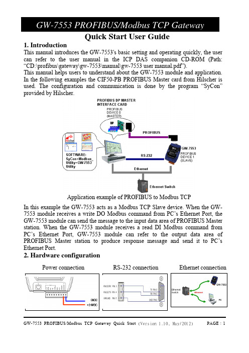
Quick Start User Guide1. Introduction This manual introduces the GW-7553's basic setting and operating quickly, the usercan refer to the user manual in the ICP DAS companion CD-ROM (Path: “CD:\profibus\gateway\gw-7553\manual\gw-7553 user manual.pdf”). This manual helps users to understand about the GW-7553 module and application. In the following examples the CIF50-PB PROFIBUS Master card from Hilscher isused. The configuration and communication is done by the program “SyCon” provided by Hilscher.Application example of PROFIBUS to Modbus TCP In this example the GW-7553 acts as a Modbus TCP Slave device. When the GW-7553 module receives a write DO Modbus command from PC’s Ethernet Port, the GW-7553 module can send the message to the input data area of PROFIBUS Master station. When the GW-7553 module receives a read DI Modbus command from PC’s Ethernet Port, GW-7553 module can refer to the output data area of PROFIBUS Master station to produce response message and send it to PC’s Ethernet Port.2. Hardware configurationPower connectionPROFIBUS connectionHere we recommend users to use the standard PROFIBUS cable and connector (DB9 male). It is only needed to use D-type connector via PROFIBUS cable to connect PROFIBUS Master station and GW-7553 module. PROFIBUS Master station and GW-7553 module belong to terminal equipments in this example, thus we need to enable the terminator resistor inthe D-type connector.Address setting The GW-7553 is a slave device of PROFIBUS DP protocol. The station address of GW-7553 can be set by DIP switch. The DIP switch can be seen by open the cover, as shown in the below. The range of DIP switch is 0~126, here we setGW-7553 module’s DIP switch to 1.LED status indicatorLEDStatus Description flash When the GW-7553 is a Modbus Slave device and receiving query message form Modbus Master device, PWR led will flash.onPower supply is ok. The firmware has loaded. PWR off Power supply has failed.ERR flashWhen the GW-7553 connects with the utility tool, it will flashfast (flash once about 55ms).When the GW-7553 has diagnostic message, it will flash slowly(flash once about 220ms). DIP switch (SW1) Stationaddress1 2 3 4 5 6 7 811 0 0 0 0 0 0 010 0 1 0 1 0 0 0 031 1 1 1 1 1 0 0 0Note:1=>ON, 0=>OFFonThe connection is error with PROFIBUS Master device orPROFIBUS system configuration is not correct.off PROFIBUS system configuration is correct. It is normal operation. onData exchange mode. It is normal operation. RUN off GW-7553 module is not in data exchange mode.3. Establish connection with GW-7553Before establish the connection between DP-Master and GW-7553, usersshould obey the following steps first.4. Software configuration GSD filePlease copy the GSD file (IPDS0C0D.gsd) and the bitmap file (ICP_7553. bmp, GW_7553.bmp) from the CD of the GW-7553 module into the Profibus configuration tool.File ->CopyGSD(Directory: --> CD:\profibus\gateway\gw-7553\gsd\)the example of how to load GSD fileHere, we use the hilscher CIF50-PB PROFIBUS communication interface to show how to load GW-7553’s GSD file step by step.Set the parameters of the GW-7553 The user needs to change “Modbus Type” to Slave, “Modbus Format” to Modbus TCP and use the default value in the other parameters in this example. Please refer to user manual section 4.3 The Configuration of theSet the modules of the GW-7553 The modules of the GW-7553 are described below.● System setting module :3 byte out● Output module :Output Relay/Coil → 1~32 BytesOutput Register → 1~64 Words● Input module :Input Relay/Coil → 1~32 BytesInput Register → 1~64 WordsIn this example, we configure a “System Setting” module, an “Output Relay/Coil--2 Byte” module and an “Input Relay/Coil--2 Byte” module, as follows.When the user finishes the configuration and saves setting in the PROFIBUS Master station successfully, the 'RUN' LED indicator of GW-7553 is turned on. That shows the GW-7553 working in the data exchange mode.Click <Online->Download> to download the setting into PROFIBUS Master stationSet the network configuration of the GW-75531. Open MiniOS7 utility and press “F12” to find IP address of GW-7553.2. Open web browser (ex. IE). Enter IP address of the GW-7553 in theAddress field and press “Enter ” to connect to GW-7553, and then enter default password (“icpdas”) to login to GW-7553 in Login page.3. Click “IP Setting” to set the network configuration of the GW-7553(please refer to user manual section 6.2). The network configuration ofthe GW-7553 must have the same domain and different IP with the PC(ex: PC’s IP =192.168.0.106, MASK =255.255.0.0; GW-7553’s IP=192.168.0.107, MASK=255.255.0.0).4. Press “Save to Device” to save IP setting to EEPROM of GW-7553135. GW-7553 module communication testThis demo uses utility “MBTCP” on the PC to communicate with the GW-7553. The User can download it on the web site: /pub/cd/8000cd/napdos/modbus/modbus_utility/. The settings of the “MBTCP” are shown in the below.Input GW-7553’s IP (ex: 192.168.0.107) and click “Connect” button PROFIBUS input test--Send command to write DO of the GW-7553The user needs to input command (” 01 0F 00 00 00 10 02 FF FF”) here andclick <Send Command> button to send Modbus command and then MBTCPcan receive response message (” 01 0F 00 00 00 10”). The user can find byte0, 1 of input data area of PROFIBUS Master device have changed into“0xFF” at this time, as shown in the below.Send modbus command (output data: 0xFF, 0xFF)Receive “0xFF” in input data area of PROFIBUS Master stationtype Representation Value Module ByteDataInput 0 Byte Hex 0xFFInput moduleInput 1 Byte Hex 0xFFPROFIBUS output test--Send Command to read DI of the GW-7553The user needs to input command (” 01 02 00 00 00 10”) in MBTCP and click <Send Command> button to send Modbus command and then MBTCP can receive response message (” 01 02 02 00 00”). In this message, the user can know the value of DI0 & DI1 is “0” in the GW-7553.--Send output data to write DI of the GW-7553 by the PROFIBUS Master The user needs to set “0xFE” & “0xDC” in byte 3 & byte 4 of output data area of PROFIBUS Master device and then set the value of the first byte from 0 to 1 to trigger the data output command.--Send command to read DI of the GW-7553 againNow the user can input command (” 01 02 00 00 00 10”) in MBTCP and click <Send Command> button to send Modbus command again. Then MBTCP can receive response message (” 01 02 02 FE DC”). In this message, the user can know the value of DI0 & DI1 have changed into “0xFE” & “0xDC” in the GW-7553, as shown in the below.Set output data and trigger output data commandModule Byte Data type Representation Value Output 0 Byte Hex 0x00 → 0x01 Output 1 Byte Hex 0x00 SystemmoduleOutput 2 Byte Hex 0x00 Output 3 Byte Hex 0x00→ 0xFE Outputmodule Output 4 Byte Hex 0x00→ 0xDCSend Modbus command to read DI of the GW-7553 and receive data (0xFE, 0xDC)。
使用Reqtify链接Doors和Simulink操作指南
使用Reqtify链接Doors 和Simulink操作指南1.目的Rational Doors是目前常用的需求管理工具,Simulink是一种常用的设计工具,Reqtify可以通过设置可以将Doors和Simulink进行链接而实现需求与设计的追踪,本文通过建立一个案例将Doors和Simulink进行链接,使读者对Reqtify 工具的使用有进一步的了解。
2.工具介绍2.1.DoorsIBM Rational DOORS是面向管理者、开发者、测试人员及整个产品生命周期的需求管理平台。
DOORS可以将项目开发过程中产生的各级需求和与需求相关的文件进行链接管理,同时能够对需求进行影响分析。
DOORS自带数据库,可以在多个项目间共享文件,便于文件的保存、备份及项目复用。
此外DOORS 还支持可疑链接的自动检测、基于需求条目的权限管理等。
图 1 IBM Rational DOORS操作界面DOORS的主要功能如下:a)项目数据库的结构化管理;b)需求的条目化管理;c)需求的协作开发;d)需求的链接、跟踪、管理;e)需求变更、影响分析;f)需求的历史信息记录;g)需求的属性定义;h)需求访问的权限管理;i)数据的备份和恢复;j)需求报告的导出。
2.2.ReqtifyReqtify软件是法国达索公司专门针对基于文件的、高度可定制的、易用的需求追踪和影响分析工具。
在产品开发全生命周期中,Reqtify可以为从产品需求、设计到实现过程的追踪提供最高效的解决方案。
Reqtify在世界航空、汽车、轨道交通等领域有非常广泛的应用,包括AIRBUS、THALES、EADS、RENAULT、TOYOTA、Ford、GM、Valeo、ALSTOM等都在开发过程中使用Reqtify进行需求追踪和影响分析。
使用Reqtify工具可以进行覆盖度统计、上下文影响分析、需求跟踪、版本管理和定制报告等。
与其他基于数据库的需求管理工具不同,Reqtify强大的兼容性使其能从各种类型的文件中提取数据,建立需求、方案、模型、代码和测试用例之间的链接,保证每条需求都能被实现和验证,无需改变现有研发模式即可在项目的任意阶段中使用。
CMM实践-利用RequisitePro进行需求管理[1]
![CMM实践-利用RequisitePro进行需求管理[1]](https://img.taocdn.com/s3/m/5b0a2740e45c3b3567ec8b75.png)
CMM实践-利用RequisitePro进行需求管理[1]需求管理中的问题在CMM3中需求管理(RM)关键过程域是非常重要的一个环节。
在我们公司CMM3级的实践中,需求管理往往是非常花费成本的一个工作,比如,在需求分析、建立需求跟踪矩阵等活动中,如果是一个团队或是几个小组在进行协作时,会有大量的Word、Excel文件需要在不同的人员间传递,其间即使用了类似VSS等工具,仍然没办法避免繁琐低效的工作方式,其间会产生例如文档传递不顺畅、协作人员的需求用例重叠、扩展需求遗漏等等问题,在实施CMM3时,此环节更为公司增加了大量运作成本。
比如,在多人协作完成需求分析,对所有需求用例进行管理的活动中,需求人员只能根据前面的需求调研报告,所有的人使用同一份Word文档模版,分别详细分析与描述属于自己任务内的需求用例,然后负责人再把每个人写好的Word文档进行合并,这种合并完全是手工的合并,同时,对于每个人需求分析的情况,只能阅读所有的文档内容才能检查出是否有所遗漏等严重问题。
再比如,公司在使用最原始方法建立需求跟踪矩阵时,往往是用一个Excel表,列出一个二维表,把软件生存期的几个阶段做为几列,例如“需求”,“设计”、“编码”、“测试”、“发布”等,然后首先由需求分析人员在第一列的“需求用例”上,列出所有的需求点,然后再把这个Excel表交给设计人员,再由设计人员在第二列的“设计”上,列出每个需求对应的设计项,这样一直传递下去。
其间这张表也不知经过了多少人的手,一旦其中某阶段一项做了修改,很难安全保障正确的向前追溯。
如果为了解决以上问题,公司自行开发一些管理工具,仍然需要花较大成本。
Rational RequisitePro特性IBM® Rational® RequisitePro® 解决方案是一种需求和用例管理工具,能够帮助项目团队改进项目目标的沟通,增强协作开发,降低项目风险,以及在部署前提高应用程序的质量。
- 1、下载文档前请自行甄别文档内容的完整性,平台不提供额外的编辑、内容补充、找答案等附加服务。
- 2、"仅部分预览"的文档,不可在线预览部分如存在完整性等问题,可反馈申请退款(可完整预览的文档不适用该条件!)。
- 3、如文档侵犯您的权益,请联系客服反馈,我们会尽快为您处理(人工客服工作时间:9:00-18:30)。
Rational RequisitePro 用户手册目录第一章: 介绍 (4)1.1欢迎来到R A TIONAL R EQUISITE P RO T UTORIAL (4)1.2读者 (4)1.3特征 (4)1.4模块是怎样组织的? (4)1.5练习怎样? (5)1.6我要按顺序阅读这些模块吗? (5)1.7链接怎样? (5)1.8完成本手册需要多长时间? (5)1.9下一章是什么? (5)第二章需求管理 (6)2.1什么是需求管理? (6)2.2需求管理为什么重要? (6)2.3项目失败的原因 (6)2.4管理需求时考虑的的问题 (6)2.5概要 (7)2.6下一章是什么? (7)第三章REQUISITEPRO介绍 (7)3.1R EQUISITE P RO组件视图 (7)3.2一个R EQUISITE P RO项目 (8)3.3使用项目模板 (9)3.3工具栏 (10)3.4与需求文档一起工作 (10)3.5组织和跟踪需求 (11)3.6练习 (13)3.7概述 (14)3.8下一章是什么? (14)第四章记录需求 (15)4.1文档模板 (15)4.2与文档一起工作 (16)4.3需求 (16)4.4练习 (17)4.5概述 (20)4.6下一章是什么? (20)第五章组织需求 (21)5.1需求类型 (21)5.2需求属性 (21)5.3视图 (22)5.4练习 (23)5.5概述 (24)5.6W HAT'S NEXT? (24)第6章跟踪需求 (25)6.1管理变更需求 (25)6.2可跟踪性 (25)6.3可疑的连接 (25)6.4层次 (26)6.5视图 (26)6.6查询(过滤和排序) (27)6.7练习 (27)6.8概述 (32)6.9下一章是什么 (32)第一章: 介绍1.1 欢迎来到Rational RequisitePro TutorialRational RequisitePro Tutorial是一个介绍RequisitePro和Rational需求管理工具的联机用户手册。
下面介绍RequistPro的一些主要特征,这将帮助您成功地管理项目(Project),您也有机会使用RequistePro来创建一个项目并与现有的项目协同工作。
1.2 读者如果您是开发团队的一员(分析员,经理,或开发者),但不熟悉需求管理过程和RequisitePro, 就请阅读该手册。
为了更好的利用该手册,您应当对Microsoft的Windows 操作系统有一个基本的了解。
1.3 特征手册的设计使得你可以根据喜好来最大化屏幕。
在每个文本的最后一行有导航键。
任何时候,可以单击双箭头按钮返回到主菜单。
并选择您想浏览的模块。
单击超链接文本,将打开一个窗口,提供更多概念性的信息。
当单击灰色的按钮,一个窗口打开,提供具体项的图形说明。
当看完文本或图形后,关闭窗口,并重新阅读这模块。
1.4 模块是怎样组织的?下面的模块组织如下:∙模块2(第二章,下同),需求管理:包括需求管理的定义,解释为什么需求管理重要,当你开始在一个项目中管理需求时你应当回答的一列问题。
∙模块3,RequisitePro介绍:描述了这个软件的组件,你有机会使用这个软件自带的模板来创建一个项目。
∙模块4,记录需求:说明怎样在RequisitePro中记录需求。
将介绍RequisitePro 自带的模板,这些模板帮助你组织你的项目。
在这模块的结尾,将给您展示怎样使用模板来创建文档,并在这些文档中创建需求。
∙模块5,组织需求:说明怎样使用RequisitePro来组织和描述需求,并根据你选择的查询和排序方式在表框中查看它们。
通过利用模块4中创建文档的练习,你将有机会经历这些特征。
∙模块6,跟踪需求:向你展示,你怎样使用RequisitePro建立和跟踪需求之间的关系,你将与本手册提供的项目一起工作。
∙模块7,高级特征:列出了几个对RequisitePro的高级用户有用的特征。
∙模块8,其它信息:提供其它信息资源的链接。
1.5 练习怎样?在模块3,4,5中,将引导你经历使用RequisitePro创建项目和需求文档的全过程。
这将让你熟悉RequisitePro提供的一些模板。
在模块6中,你将协同RequisitePro提供的样本项目Learning Project,来做练习。
这个项目包括一个虚构的名为ClassicsCD公司的需求文档。
该项目也包括在一个活动的项目中产生的需求及文档的一些类型。
1.6 我要按顺序阅读这些模块吗?这些模块设计成按顺序阅读;每个模块建立在前一个的基础上。
模块2和3提供的背景信息对所有新用户都有帮助。
模块3,4及模块5包括了练习,在练习中文档和需求被处理而且在后面的练习中会使用到,因此它们必须按顺序完成。
虽然模块6建立于先前模块提供的概念信息,但练习也可以独立其它模块完成。
模块7和8是选择项;它们给高级用户提供了帮助信息,但即使没有完成它们,你也将能够成功使用RequisitePro.1.7 链接怎样?历遍本手册,你有机会单击按钮来阅读关于需求管理过程深层次的讨论,而且查看屏幕上的内容,这些内容你将在练习中遇到。
虽然本手册集中于帮助你使用RequisitePro,但我们承认,甚至一个优秀的软件也不能解决由不适当的需求管理过程可能导致的问题。
本手册不试图去教那些过程,但它提供了使用RequisitePro的介绍和背景。
在工具栏(启动程序的时候出现)上单击Help按钮,并选择Let's Go RequisitePro, 可以获得关于需求管理的帮助信息。
这里(This screen)提供许多资源,包括几本白皮书和需求管理漫游。
1.8 完成本手册需要多长时间?读完整个用户手册需要8个小时。
但是你可以从任何模块开始或停下来,下次在从原来停下来的地方开始。
1.9 下一章是什么?模块2提供了需求管理过程的一般看法。
访问模块2,单击右箭头。
第二章需求管理2.1 什么是需求管理?理解需求管理的第一步就是在公共词汇上取得一致。
需求可以定义为系统必须提供的性能。
需求管理是:∙获取,组织和记录一个系统需求的系统化方法。
∙客户和项目团队就系统需求改变而建立和维护一致意见的过程。
需求的一致定义了项目的成功。
这样,它明白的发现需求是什么,在变化的每个事件时记下,组织并跟踪它们。
成功需求管理的结果是满足客户需要并按时按预算完成的优质产品。
2.2 需求管理为什么重要?要成功,项目必须在规定的时间和预算内发布,也必须能处理客户的需求。
然而,因为在项目的过程当中,需求可能会改变,所以这不是一件简单的任务。
(事实上,一些改变是不可避免甚至是值得做的;这是指你和你的团队正在和跟这个项目有风险关系的人共事。
)通过组织和跟踪需求并管理需求变化,提高在规定时间和预算内完成该项目,并发布客户想要的产品的可能性。
2.3 项目失败的原因研究表明大量的项目没有取得成功;它们超出预算,超过截止日期,或者甚至中途放弃。
项目也许会完成,但因为需求改变了,客户可能没有发现它们的价值。
在1994年的调查中,Standish Group列出了下列最常被引用为项目失败的因素:∙缺少用户参与∙不完整的需求和规约∙改变需求和规约其它经常被引用的因素包括一些需求的时间敏感的本质,撰写文档的困难,特征蔓延(整个开发过程中产品特征的无计划变更的增加),不能协调人们之间的努力,改变需求的原始资料,不能控制和跟踪需求的数目。
RequisitePro提供易于使用的工具管理变更需求,因此增加了发布客户想要的的产品并按时这样做的可能性。
2.4 管理需求时考虑的的问题1.您正设法解决什么业务问题,谁在这决定中担当风险?2.哪些特征是不可缺少的?3.对被提议的方案,怎样用技术和非技术人员都能理解的语言描述?4.那些是可获得的资源(时间,人力,金钱)?5.如何设定需求的优先级?6.如何确认系统将像描述的那样运转并执行可接受的速度和效率?7.如何跟踪需求之间的依赖关系?8.如何限制和商议系统的变化,从而使产品能完成及风险担当者仍然参与?9.需求变化的评审和解决的程序是什么?2.5 概要本模块定义了需求管理,说明了需求管理为什么重要,描述了项目失败的一些原因,并列举了管理需求项目时应当考虑的问题。
2.6 下一章是什么?模块3介绍了RequisitePro的一些主要特征。
浏览模块3,单击右箭头。
第三章RequisitePro介绍3.1 RequisitePro组件视图RequisitePro是一个需求管理工具,它帮助团队综合的管理项目需求并使得合作和沟通更容易。
RequisitePro由不同的工作区组成,但相关的工作在这里完成。
工作区从工具栏中开启。
所有需求信息存储在数据库里;视图工作区(View Workplace)提供访问那些信息的通道。
RequisitePro将Microsoft Word和数据库集成在一起,因此让你能够用自然语言清晰的表达需求,并同时组织它们。
你可以不费力的在Word和数据库之间移动来组织需求,设定优先级,跟踪它们的关系,并跟踪需求变化。
RequisitePro组件视图3.2 一个RequisitePro项目在RequisitePro里,一个项目包括数据库它也许包括文档。
包括在数据库里的是文档类型,需求类型和操作符,讨论,以及关于需求跟踪,用户和组安全的信息。
当你创建一个项目,有指定了下面的:∙文档类型(document types),例如glossary document, vision statement, and use cases (它概括了系统行为);∙需求类型(requirement types),跟features, use cases, supplementary specifications 等联系在一起的需求;∙需求属性(requirement attribute s),根据priority, status, stability, 及其它你定义的特征来描述需求。
需求跟踪能力(requirement traceability),显示了需求之间的关系。
这些结构化信息包含在项目和文档模板里,RequisitePro提供这些模板帮助你开始使用。
3.3 使用项目模板你可以从现有的项目结构创建一个新项目;当你那样做时,新项目将拥有与现有项目相同的文档类型,需求类型,属性,安全设置。
RequisitePro提供下面的项目模板:用列模板(Use-Case Template),(使用一种用例技术)惯用模板(Traditional Template),(使用标准软件需求)复合模板(Composite Template),(用例和惯用模板的结合)创建新模板(Make New Template)你也可以从一个空白模板中创建一个项目。
