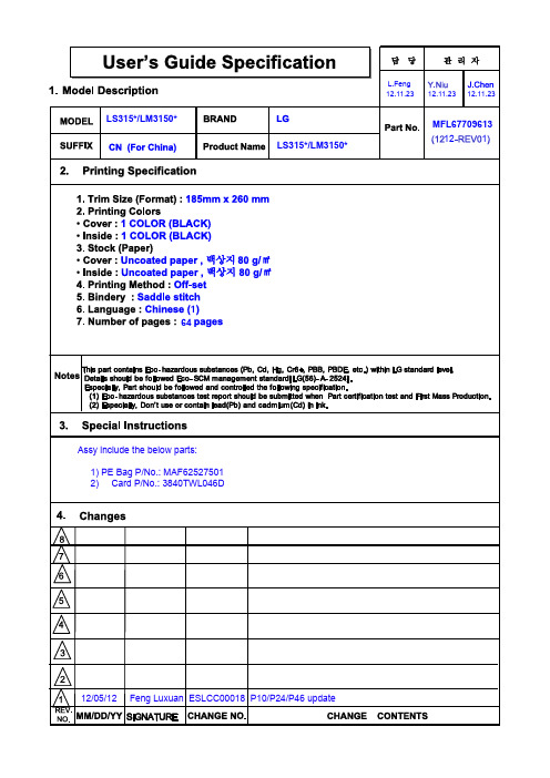
大牌电商日报:Swatch上半财年销售额大跌12%
WI-FI智能开关WFSW15用户操作指南说明书
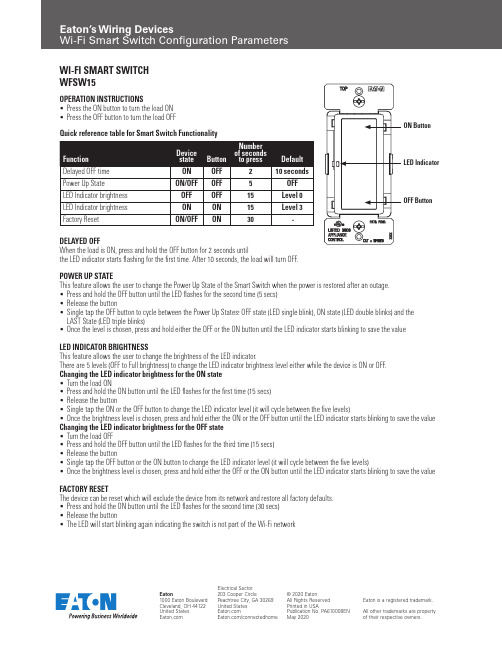
WI-FI SMART SWITCH WFSW15OPERATION INSTRUCTIONS• Press the ON button to turn the load ON • Press the OFF button to turn the load OFFDELAYED OFFWhen the load is ON, press and hold the OFF button for 2 seconds untilthe LED indicator starts flashing for the first time. After 10 seconds, the load will turn OFF.POWER UP STATEThis feature allows the user to change the Power Up State of the Smart Switch when the power is restored after an outage. • Press and hold the OFF button until the LED flashes for the second time (5 secs) • Release the button• Single tap the OFF button to cycle between the Power Up States: OFF state (LED single blink), ON state (LED double blinks) and the LAST State (LED triple blinks)• Once the level is chosen, press and hold either the OFF or the ON button until the LED indicator starts blinking to save the value LED INDICATOR BRIGHTNESSThis feature allows the user to change the brightness of the LED indicator.There are 5 levels (OFF to Full brightness) to change the LED indicator brightness level either while the device is ON or OFF. Changing the LED indicator brightness for the ON state • Turn the load ON• Press and hold the ON button until the LED flashes for the first time (15 secs) • Release the button• Single tap the ON or the OFF button to change the LED indicator level (it will cycle between the five levels)• Once the brightness level is chosen, press and hold either the ON or the OFF button until the LED indicator starts blinking to save the value Changing the LED indicator brightness for the OFF state • Turn the load OFF• Press and hold the OFF button until the LED flashes for the third time (15 secs)• Release the button• Single tap the OFF button or the ON button to change the LED indicator level (it will cycle between the five levels)• Once the brightness level is chosen, press and hold either the OFF or the ON button until the LED indicator starts blinking to save the valueFACTORY RESETThe device can be reset which will exclude the device from its network and restore all factory defaults. • Press and hold the ON button until the LED flashes for the second time (30 secs) • Release the button• The LED will start blinking again indicating the switch is not part of the Wi-Fi networkQuick reference table for Smart Switch FunctionalityWI-FI SMART DUPLEX RECEPTACLE WFTRCR15OPERATION INSTRUCTIONS• Press the ON/OFF button to turn the load ON • Press the ON/OFF button again to turn the load OFFDELAYED OFFWhen the load is ON, press and hold the ON/OFF button for 2 seconds untilthe LED indicator starts flashing for the first time. After 10 seconds, the load will turn OFF.POWER UP STATEThis feature allows the user to change the Power Up State of the Smart Receptacle when the power is restored after an outage. • Press and hold the ON/OFF button until the LED flashes for the second time (5 secs) • Release the button• Single tap the ON/OFF button to cycle between the Power Up States: OFF state (LED single blink), ON state (LED double blinks) and the LAST state (LED triple blinks)• Once the level is chosen, press and hold the ON/OFF button until the LED indicator starts blinking and the value will be saved LED INDICATOR BRIGHTNESSThis feature allows user to change the brightness of the LED indicator.There are 5 levels (OFF to Full brightness) to change the LED indicator brightness level either while the device is ON or OFF Changing the LED indicator brightness for the ON state • Turn the load ON by pressing the ON/OFF button• Press and hold the ON/OFF button until the LED flashes for the third time (15 secs)• Release the ON/OFF button• Single tap the ON/OFF button to change the LED indicator level (it will cycle between the five levels)• Once the brightness level is chosen, press and hold the ON/OFF button until the LED indicator starts blinking and the value will be saved Changing the LED indicator brightness for the OFF state • Turn the load OFF by pressing the ON/OFF button• Press and hold the ON/OFF button until the LED flashes for the third time (15 secs) • Release the button• Single tap the ON/OFF button to change the LED indicator level (it will cycle between the five levels)• Once the brightness level is chosen, press and hold the ON/OFF button until the LED indicator starts blinking to save the valueFACTORY RESETThe device can be reset which will exclude the device from its network and restore all factory defaults • Press and hold the ON/OFF button until the LED flashes for the fourth time (30 secs) • Release the button• The LED will start blinking again indicating the receptacle is not part of the Wi-Fi networkQuick reference table for Smart Duplex Receptacle FunctionalityWI-FI SMART UNIVERSAL DIMMER WFD30OPERATION INSTRUCTIONS• Press the ON button to turn the lights ON at the previously selected level • Press the OFF button to turn the lights OFF• The bottom LED indicates that the dimmer is turned ON (Default)• Press and hold the ON button for 2 seconds for full brightnessDELAYED OFFWhen lights are ON, press and hold the OFF button for 2 seconds until the LED indicator blinks. After a 10 second delay, the lights will fade OFF.DIMMING LEVEL ADJUSTMENTFor maximum compatibility with different load types, WFD30 allows the user to set the minimum level. Also, to save on power consumption WFD30 allows the user to set the maximum level.• After restoring power and adding the device to the Wi-Fi network , press the ON button to turn on the light • Press and hold the ON button for five seconds until the dimmer LED indicators begin to cycle rapidly• Release the ON button. Dimmer will set the light to the previously saved minimum level. During initial setup, the light will set to the factory minimum default• Press either the dim or brighten buttons to change the minimum level until the light output is acceptable• Press and release the ON button once. The dimmer LEDs will start to cycle rapidly again and the dimmer light will go to previously saved maximum level• Press either the dim or brighten buttons to change the maximum level until the light output is acceptable • Press and release the ON button, the LED indicator starts blinking and the value will be savedNOTE - To restore the default min/max, repeat the steps above and adjust light levels to full min/max settings by pressing dim/brighten buttons until the light output no longer changes.NOTE - The user can ignore setting max or min by pressing the ON/OFF button without changing the dimming level.RAPID START FEATURE (DISABLED BY DEFAULT)This feature ensures that LED/CFL lights turn on when the dimmer preset level is low. With this setting enabled, the lights will momentarily be brighter than the preset level (less than one second) and then dim down to the preset level. Depending on the type of light used, this feature may not be needed.• After restoring power and adding the device to the Wi-Fi network, press the ON button to turn on the light • Press and hold the ON button for 10 seconds until the dimmer LED indicators begin to blink for the second time • Release the ON button. LED indicators will start flashing fast to indicate the state has changed NOTE - To disable/enable the RAPID START FEATURE, repeat the steps above again.Quick reference table for Smart Universal Dimmer Functionality LED Light Level Indicator Press to DIMPress to BRIGHTENON/OFF ButtonWI-FI SMART UNIVERSAL DIMMER (cont.)WFD30LED INDICATOR BRIGHTNESSThis feature allows the user to change the brightness of the LED indicator.There are 5 levels (OFF to Full brightness) to change the LED indicator brightness level either while the dimmer is ON or OFF state Changing the LED indicator brightness for the ON state• Turn the light ON• Press and hold the ON button for 15 seconds until the LED indicator flashes for the third time• Release the button• Use the ON or OFF buttons to change the LED indicator level (it will cycle between the five levels)• Once the level is chosen, press and hold the ON button until the LED indicator starts blinking to save the valueChanging the LED indicator brightness for the OFF state• Turn the light ON• Press and hold the OFF button for 15 seconds until the LED indicator flashes for the fourth time• Release the button• Use the ON or OFF buttons to change the LED indicator level (it will cycle between the five levels)• Once the level is chosen, press and hold the OFF button until the LED indicator starts blinking to save the valuePOWER UP STATE (OFF STATE BY DEFAULT)This feature allows the user to change the Power Up State of the Smart Dimmer when the power is restored after an outage.• Turn the light OFF• Press and hold the OFF button for five seconds until the LED indicator flashes for the second time• Release the button• LED will blink either at the highest level, indicating the Power Up State is ON, or in the middle level, indicating thePower Up State is the LAST state or the lowest level indicating the Power Up State is OFF• Use the On or OFF button to cycle between the three states• Once the level is chosen, press and hold the OFF button until the LED indicator starts blinking to save the valueRAMP TIME RATE (3 SECONDS BY DEFAULT)This feature is to enable/disable a 3 second ramp time when turning the device ON/OFF. When enabled (default), the dimmer will ramp the load brightness up or down over a 3 second period when turned ON or OFF respectively. When disabled, the dimmer will instantly turn ON/OFF.• Turn the light ON• Press and hold the OFF button for 10 seconds until the LED indicator blinks for the third time• Release the button• LED indicators will start flashing fast to indicate the state has changedNOTE - to change the RAMP TIME RATE, repeat the steps aboveFACTORY RESETThe device can be reset which will exclude the device from its network and restore all factory defaults.• Turn ON the dimmer• Press and hold the ON button for 30 seconds until the LED indicator blinks for the fourth time• Release the button• LED indicator will start flashing fast while it is being reset• The LED indicator will then start blinking at a normal rate indicating the dimmer is not part of a Wi-Fi network。
瑞米特RMT-615系列温度控制器使用说明书
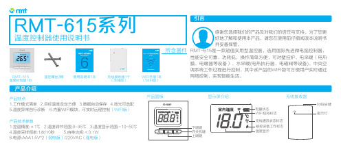
产品面板RMT-615系列温度控制器使用说明书感谢您选择我们的产品及对我们的信任与支持。
为了您更 好地了解和使用本产品,请您在使用前仔细阅读本说明书 并妥善保管。
RMT-615是一款超值实用型温控器,选用国际先进微电脑控制器,性能安全可靠、功耗低,操作简单方便,可对壁挂炉、电采暖(电热膜、电暖器等设备)、水采暖(电热执行器、电磁阀等设备)、中央空调系统工作过程进行控制,其中该产品的WIFI版可方便用户实时通过网络控制,实现智能生活。
显示屏介绍RMT-615温度控制器1台固定螺丝2颗使用说明书1本产品技术参数1.控温精度:±1℃2.温度调节范围:0~35℃3.温度显示范围:-10~50℃4.温度采样频率:1次/10秒5.自身功耗:<0.1W6.电源:AAA1.5V*2/220VAC (弱电版)(强电版)产品特点1.工作模式简单2.目标温度设定方便3.数据自动保存4.背光可选配5.温度异常自行诊断6.内置WIFI模块,可实时远程控制(WIFI版) (无线版)无线接收器无线接收器1个WIFI手册1本(WIFI版)本手册所提及的产品规格和资讯仅供参考,如有更改,恕不另行通知!设定温度在主界面下,按上调键或下调键调整目标温度,液晶显示“设定温度”,按开关机键保存并退出至主界面。
波动温度在主界面下,长按上调键3秒,进入波动温度设置界面,按上调键或下调键调整,波动幅度可设置为0.5或1℃,按开关机键保存。
开关机 长按开关机键5秒,开机或关机。
低电提示电池全显,电量充足,电池闪烁,需要更换新电池。
背光(选配)用户在操作过程中背光点亮;操作完成后背光熄灭以节省电量。
安装说明1.打开后盖,将后盖固定在墙上。
2.用户根据需要,按照接线图,连接好被控设备。
3.安装两节七号电池,将前面板固定在后盖上。
(弱电版)4.用户设置好相关参数后,温控器即可自动运行。
① NO常开点② COM公共端③ NC常闭点接线图①②③① 信号线接口② 电源线接口(弱电版)北京瑞米特科技有限公司(强电版)阀开N输出阀关L输入N输入NC NOCOM适用于电地暖、电热执行器等需要温控器提供220VAC的采暖设备L输入N输入适用于壁挂炉等不需要温控器提供220VAC的采暖设备。
各种手表的ETA机芯优缺点详细分析
各种手表的ETA机芯优缺点详细分析一、ETA的历史起源ETA,这个控制了当今瑞士表机芯远远超过半壁江山的厂家,年产量过亿的统芯生产者,确实提供了大量的机芯给Tissot,也给了Omega,还有更多其他著名的厂家和品牌,了解了ETA,也给了解了相当一部分的瑞士手表,现在,就让我们看看这个瑞士机芯巨人。
1793年,在瑞士Fontainemelon地区,人们发现又有一座新表厂创建了,这就是ETA集团历史的开始。
1855年又在Grenchen地区开设了另外一家专门用于制造“半成品表芯(Ebauches)”,又被称之为“空白机芯”的工厂,就是这家工厂,后来更名成了ETA。
1926年,当时的瑞士已经有了多家实力雄厚的空白机芯制造厂商,这些厂商互相联合,成立了以一家空白机芯制造商的股份公司Ebauches SA。
1983年,当今世界最大的腕表生产集团之一的斯沃琪集团“Swatch Group”,SMH成立了。
并且将原先的Ebauches SA归入旗下,随后更名为ETA SA Fabriquesd`Ebauches。
今天的ETA 也就是斯沃琪集团的机芯巨人。
ETA现在拥有9千多名员工,并且早在1996年就已经达到了每年上亿的机芯产量。
公司在瑞士本土,法国,德国,泰国,马来西亚和中国都有装配或者制造工厂。
如果说Breguet,Glashutte Original,Omega,Jaquet Droz等这些品牌是斯沃琪集团的顶级品牌,撑起了整个斯沃琪集团门面的话,那么,ETA就是整个集团内部真正的钢筋水泥基础。
ETA基石在斯沃琪集团的主要业务包括1、保证瑞士手表的技术研究:2、发展以低廉价格进行的配件,机芯和整表的大规模生产。
3、掌握手表和生产机械的所有技术:4、批量装配机芯和手表。
从上面的业务目标不难看出,ETA不仅负责机芯本身的开发和研制,更负责自身生产设备的设计和开发。
从思路,到设计,到研发,到少量测试,到批量生产,更到质量监控,ETA把整个流程控制得有条不紊。
Fitbit Inspire 3手冊版本1.3说明书

使用手冊版本 1.3目錄開始 (6)包裝盒內物品 (6)為智慧手環充電 (6)設定 Inspire 3 (8)在 Fitbit 應用程式中查看您的資料 (9)解鎖 Fitbit Premium (10)佩戴 Inspire 3 (11)整日佩戴和運動時的佩戴方式 (11)慣用手 (12)將 Inspire 3 佩戴在夾扣上 (12)夾扣位置 (13)佩戴與保養技巧 (14)更換錶帶 (14)移除錶帶 (14)安裝錶帶 (15)基本資訊 (16)導覽 Inspire 3 (16)基本導覽 (16)快速設定 (17)調整設定 (19)顯示設定 (19)靜音模式 (20)其他設定 (20)查看電池電量 (21)調整「螢幕常亮」 (21)關閉螢幕 (22)錶面和應用程式 (23)變更錶面 (23)開啟應用程式 (23)尋找手機 (24)2手機通知 (25)設定通知 (25)查看傳入通知 (25)管理通知 (26)關閉通知 (26)接聽或拒接來電 (27)回覆訊息 (Android 手機) (28)計時 (29)設定鬧鐘 (29)解除或休眠鬧鐘 (29)使用計時器和碼錶 (30)活動與健康 (31)查看統計資料 (31)追蹤每日活動目標 (31)選擇目標 (32)追蹤每小時的活動 (32)追蹤您的睡眠 (32)設定睡眠目標 (33)深入瞭解長期睡眠行為 (33)瞭解您的睡眠習慣 (33)管理壓力 (33)練習引導式呼吸 (33)查看壓力管理分數 (34)進階的健康指標 (34)運動和心臟健康 (35)自動追蹤您的運動 (35)使用運動應用程式追蹤與分析運動 (35)GPS 要求 (35)自訂運動設定 (37)查看您的運動摘要 (38)查看您的心率 (38)預設心率區間 (39)自訂心率區間 (40)賺取活動區間分鐘數 (40)3接收心率過高通知 (41)檢視您的日常準備分數 (42)檢視心肺健康分數 (42)分享您的活動 (42)更新、重新啟動和清除 (43)更新 Inspire 3 (43)重新啟動 Inspire 3 (43)清除 Inspire 3 (44)疑難排解 (45)找不到心率訊號 (45)沒有 GPS 訊號 (46)其他問題 (46)一般資訊和規格 (47)感應器與元件 (47)材質 (47)無線技術 (47)觸覺反饋 (47)電池 (47)記憶體 (47)顯示幕 (48)錶帶大小 (48)環境條件 (48)瞭解詳情 (48)退貨政策和保固 (48)Regulatory and Safety Notices (49)USA: Federal Communications Commission (FCC) statement (49)Canada: Industry Canada (IC) atement (50)European Union (EU) (51)Argentina (53)Australia and New Zealand (53)Ghana (53)Indonesia (53)Israel (53)Japan (54)Kingdom of Saudi Arabia (54)4Malaysia (54)Mexico (54)Morocco (55)Nigeria (55)Oman (55)Paraguay (55)Philippines (56)Serbia (56)Singapore (56)South Korea (56)Taiwan (57)Thailand (60)United Arab Emirates (60)United Kingdom (61)About the Battery (61)IP Rating (62)Safety Statement (62)Regulatory Markings (62)56開始瞭解 Inspire 3—這款智慧手環能幫助您找到動力,做您喜歡的事,展現最好的自己。
艾顿Wi-Fi智能开关(EWFSW15)说明书
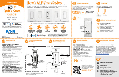
Control your lights from anywhere with Eaton’s Wi-Fi Smart Switch (EWFSW15) which replaces standard switches and features ON/OFF control. The switch can be remotely controlled using the Brightlayer Home App.Your Wi-Fi Smart SwitchFeaturesLED indicator Status indicatorSingle location installation (Black lines)Operation instructionsPrior to installationEnd User license agreementSoftware included with the Eaton product is hereby licensed to You, and Eaton retains for itself (or, if applica-ble, its suppliers) all title and ownership to any software delivered hereunder. Without Eaton’s authorization, You shall not copy, disclose or display the software, or otherwise make it available to others, and shall not attempt any sale, transfer, sublicense, reverse compilation or disassembly or redistribu-tion of the software. By using the software, You agree to the terms of Eaton’s End User License Agreement at: https:///WiFiSmartEULAAmazon, Alexa and all related logos are trademarks of , Inc. or its affiliates. Google and Google Play are trademarks of Google LLC. Wi-Fi CERTIFIED logo is a trademark of the Wi-Fi Alliance.Voice controlw ith Alexa and H ey Googleinstallation requiredSet schedules, groups, and scenesQuick Start Neutral is requiredSingle pole & 3-wayTools neededAdditional system requirementsPhillips-head ScrewdriverWire cuttersTools required for installation (not included) for the Wi-Fi Smart Switch (EWFSW15):A 2.4GHz Wi-Fi network with high-speed internetIOS 12.0 or later or Android 8.0 or later mobile device. Note: Must be connected to Wi-Fi and Bluetooth A Brightlayer Home account set-up through the Brightlayer Home App• Press ON button to turn lights ON • Press OFF button to turn lights OFF• When the lights are ON, press and hold the OFF button for 2 seconds until the LED indicator blinks. After a 10 second delay, the lights will turn offFACTORY RESET: The switch can be reset which will exclude the device from its network and restore all factory defaults.• P ress and hold the ON button until the LED indicator blinks for the second time (30 secs)• R elease the button• The LED indicator will start blinking againindicating the switch is not part of the Wi-Fi networkScan for more advanced featuresincluding adjusting the brightness level of the LED indicators and additional wiring configurationsFor color change kit installation instructions, see back pageRequires neutral for installationWARNINGS AND CAUTIONS:• T urn OFF circuit breaker or remove fuse(s) and test that power is OFF before installation process • N ever wire any electrical device with power turned ON Wiring switch HOT may cause permanent damage to switch and void warranty • I f you are not sure about any part of these instructions, please contact a licensed electrician CAUTION• Use only with 120V/AC 60Hz• Do not exceed maximum rating of switch as indicated on the device • M ust be installed and used in accordance with all national and local electrical codes • I f a bare copper or green ground connection is not available in the wallbox, contact a licensed electrician for installation • U se only #14 or #12 copper wire rated for at least 75ºC with these devicesDO NOT USE WITH ALUMINUM WIREIMPORTANT: Wi-Fi Smart Switch (EWFSW15) will not work or will be damaged if wired incorrectly and warranty will be voided. Refer to wiring instructions provided.NOTE: The Wi-Fi Smart Switch (EWFSW15) is wired directly to the light fixture. For Multi-location applications (3-way) a regular 3-way switch can be used.Safely leave room before lights turn offTwo location control using a 3-way switch (gray lines)Wi-Fi Smart Devices offer reliability with unbeatable ease o f setup. EWFSW15EWFTRCR15EWACDEWFFSC15Contact us:/chat/smarthome*********************Phone (Toll Free): 877-386-2273 Device support: Option 5 then Option 3App support: Option 2 then Option 9 Fax (Toll Free): 800-329-3055/smarthometraveler wire exists for 3-way.Set-up the Device Add your device to the Brightlayer Home AppSTEP 1 : Double click on the “ON” button on the Wi-Fi Smart Switch (EWFSW15). Status LED on the Wi-Fi Smart Switch should be blinking cyan to indicate that the device is in set-up mode. If the status LED is not blinking, refer to the Troubleshooting guide.STEP 2 : Log in to your account on the Brightlayer Home App STEP 3 : Select “Devices” optionOnce initial device is installed, additional devicescan be added using the global add (+) button.FCC STATEMENTThis device complies with Part 15 of the FCC Rules. Operation is subject to the following two conditions:1: This device may not cause harmful interference, and2: This device must accept any interference received, including interference that may cause undesired operation.NOTE: This equipment has been tested and found to comply with the limits for aClass B digital device, pursuant to Part 15 of the FCC Rules. These limits are designed to provide reasonable protection against harmful interference in a residentialinstallation. This equipment generates, uses and can radiate radio frequency energy and, if not installed and used in accordance with the instructions, may cause harmful interference to radio communications. However, there is no guarantee that interfer-ence will not occur in a particular installation. If this equipment does cause harmful interference to radio or television reception, which can be determined by turning the equipment off and on, the user is encouraged to try to correct the interference by one or more of the following measures:• Reorient or relocate the receiving antenna.• Increase the separation between the equipment and receiver.• Connect the equipment into an outlet on a circuit different from that to which the receiver is connected.• Consult the dealer or an experienced radio/TV technician for help.FCC CAUTION: Any changes or modifications not expressly approved by Eaton Wiring Devices could void the user’s authority to operate the equipment.This device complies with Industry Canada’s license-exempt RSSs. Operation is subject to the following two conditions:(1) This device may not cause interference; and(2) This device must accept any interference, including interference that may cause undesired operation of the device.EATON WIRING DEVICES LIMITED 2 YEAR WARRANTYEaton Wiring Devices warrants its Switch to be free of defects in materials and workmanship in normal use and service for a period of two years from date of original purchase. THIS TWO (2) YEAR LIMITED WARRANTY IS IN LIEU OF ALL OTHER WARRANTIES, OBLIGATIONS, OR LIABILITIES, EXPRESSED OR IMPLIED (INCLUDING ANY IMPLIED WARRANTY OF MERCHANTABILITY OR FITNESS FOR A PARTICULAR PURPOSE THAT IS IN DURATION IN EXCESS OF TWO YEARS FROM THE DATE OF ORIGINAL CONSUMER PURCHASE). NO AGENT, REPRESENTATIVE, OR EMPLOYEE OF EATON HAS AUTHORITY TO INCREASE OR ALTER THE OBLIGATIONS OF EATON UNDER THIS WARRANTY. To obtain warranty service for any properly installed Eaton Switch that proves defective in normal use send the defective Switch prepaid and insured to Quality Control Dept., Eaton Wiring Devices, 203 CooperCircle, Peachtree City, GA 30269; in Canada: Eaton Wiring Devices, 5925 McLaughlin Road, Mississauga, Ontario L5R 1B8. Eaton will repair or replace the defective unit, at its option. Eaton will not be responsible under this warranty if examination shows that the defective condition of the unit was caused by misuse, abuse, improper installation, alteration, improper maintenance or repair of damage in shipmentTroubleshooting guideWi-Fi Smart Switch color change kit installation instructionsHow to download the AppSTEP 1 :Squeeze top tabs on either side of the deviceSTEP 2 :Pull faceplate offSTEP 3 :Line up all tabs and snap the faceplate onGet your Wi-Fi Smart Device running in 3 easy steps!WarrantyLED statusQuick reference table for Wi-Fi Smart Switch (EWFSW15) functionalityNOTE: Not all products include color change kits.Available in 3 different color change kitsSymptomPossible CauseSolutionDevice doesn’t function. All LEDs are OFFA)B) C) Circuit breaker is open or trippedImproper wiring Defective switch A) B) C) Turn ON/Close the circuit breakerCheck and correct wiring Replace switch Erratic operation orflickering LEDsLoose wiring connectionsCheck wiring and following instructions provided with the deviceDevice functions normally using the switch push buttons but not from Brightlayer Home App. Purple LED indicator is blinking ON and OFF about once per secondSwitch is not included in the Wi-Fi networkA) B) C) Include the switch in the Wi-Fi network using Brightlayer Home App Check that the router is functioning properly Go through the factory reset procedure and re-add the device to the Brightlayer Home App Device functions normally using the switch push buttons but not from Brightlayer Home App. Yellow LED indicator is blinking ON and OFF about once per secondNo Wi-Fi signalCheck the routerDevice functions normally both locally and from a Brightlayer Home App but can’t be controlled from a standard 3-way switchThe 3-way wire is not connectedRefer to the wiring connection and check if the 3-way wire is connectedSwitch is warm to touch after a period of timeThis is normal if the load is within the switch limitsNo action requiredOnce selected the devices would be displayed as shown below:Note: Now the user can utilize many features that areavailable such as creating schedules, scenes, preset light levels and minimum/maximum brightness settings through the Brightlayer Home App.Next click on “Add a Device” option shown in the screen belowSelect the device type to addSTEP 3 (continued) :Amazon, Alexa and all related logos are trademarks of , Inc. or its affiliates. Google and Google Play are trademarks of Google LLC. Wi-Fi CERTIFIED logo is a trademark of the Wi-Fi Alliance.STEP 3 (continued) :For more information, visit /smarthomeDownload the AppSearch and download the Brightlayer Home App via the App Store or Google Play.Select “Create an Account” to create an account by following the instructions on the screen.Fold in half vertically with page 1 on outside, then Z-fold in horizontal direction to final folded size of 3.4 in. W x 5.5 in. H with part number facing outward.。
InSwitch ISF系列用户手册说明书

InSwitch ISF系列用户手册资料版本:V3.5—2019.03声明首先非常感谢您选择本公司产品!在使用前,请您仔细阅读本用户手册。
非本公司书面许可,任何单位和个人不得擅自摘抄、复制本书内容的部分或全部,并不得以任何形式传播。
由于不断更新,本公司不能承诺该资料与实际产品一致,同时也不承担由于实际技术参数与本资料不符所导致的任何争议,任何改动恕不提前通知。
本公司保留最终更改权和解释权。
版权所有©北京映翰通网络技术股份有限公司及其许可者版权所有,保留一切权利。
本手册图形界面约定格式意义< >带尖括号“< >”表示按钮名,如“单击<确定>按钮”。
“”带双引号“”表示窗口名、菜单名,如:弹出“新建用户”窗口。
>>多级菜单用“>>”隔开。
如“文件>>新建>>文件夹”多级菜单表示“文件”菜单下的“新建”子菜单下的“文件夹”菜单项。
提醒操作中应注意的事项,不当的操作可能会导致数据丢失或者设备损坏。
对操作内容的描述进行必要的补充和说明。
技术支持联络信息北京映翰通网络技术股份有限公司(总部)地址:北京市朝阳区利泽中园103号楼3层302电话:(8610)6439 1099 传真:(8610)8417 0089成都办事处电话:************地址:四川省成都市高新区府城大道西段399号,天府新谷10栋1406室广州办事处电话:************地址:广州市天河区棠东东路5号远洋新三板创意园B-130单元武汉办事处电话:************地址:湖北省武汉市洪山区珞瑜东路2号巴黎豪庭11栋2001室上海办事处电话:************地址:上海市普陀区顺义路18号1103室目录一、包装清单 (1)二、产品介绍 (1)2.1概述 (1)2.2 突出特点 (2)三、面板与尺寸 (3)3.1 面板介绍 (3)3.2 结构尺寸 (3)四、安装 (4)4.1 导轨安装说明 (4)4.2 壁挂安装 (5)4.2.1 壁挂式式安装 (5)4.2.2 壁挂式拆卸 (6)五、电缆接线 (7)5.1 10/100Base-TX端口 (8)5.2100Base-FX端口 (9)5.31000Base-X, 1000Base-TX SFP端口 (9)5.4 电源 (11)5.5 保护地 (12)5.6 告警 (13)六、功能说明 (14)6.1 指示灯说明 (14)6.2 拨码开关 (15)6.3 告警说明 (16)6.4 环网说明 (16)6.4.1 ISM网管交换机配置 (17)6.4.2 ISF交换机的默认环端口 (18)七、组网方式 (19)7.1单台设备组网 (19)7.2多台设备组网 (19)7.2.1环型网络 (19)7.2.2星型网络 (20)附录一InSwitch产品命名规则 (21)一、包装清单每一台出厂的ISF产品,都包含了客户现场的常用配件(如标准配件列表),当您收到我们的包裹后,请仔细检查,如果发现有缺失或者损坏现象,请及时联系映翰通销售人员。
蒂Literalmate 电动刮其 flag 系列 5000 多功能刮其说明书

Product PictureShaver series 5000SteelPrecision bladesPower Adapt sensor360-D Flexing headsIntegrated pop-up trimmerS5579/71Powerful shave, gentle on skinwith SkinIQ T echnologyThe Philips Series 5000 delivers a powerful shave, cutting now even more hair per stroke*. Equipped with advanced SkinIQ technology, the shaver senses and adapts to your hair density, for improved skin comfort.A powerful shaveMore cutting performance in every strokeFollows the contours of your faceGuides hair into the optimal cutting positionSkinIQ technologyA shaver with the power to tame beardsFor a convenient shavePowerful cleaning pod for maintenance and hygieneChoose a convenient dry or refreshing wet shaveEven-up your mustache and sideburns60 minutes of shaving from a 1-hour chargeFully charged in one hourThe electric shaver with an Eco passportA more intuitive shaving experienceWet & Dry electric shaver S5579/71 Highlights SpecificationsSteelPrecision bladesPowerful yet gentle, the 45 self-sharpening SteelPrecision blades on this Philips shaver complete up to 90,000 cutting actions per minute, cutting more hair per stroke** for a clean, comfortable finish.Power Adapt sensorThe electric shaver has intelligent facial-hair sensor that reads hair density 125 times per second. The technology auto-adapts cutting power for an effortless and gentle shave.360-D Flexing headsDesigned to follow the contours of your face, this Philips electric shaver has fully flexible heads that turn 360° for a thorough and comfortable shave.Hair-Guide precision headsThis new shape precision shaver is enhanced with hair guiding channels for optimal cutting and skin comfort.Cable-free Quick Clean Pod10x more effective than cleaning with water**, the powerful cleaning pod thoroughly cleans and lubricates your shaver in just 1 minute. Using it helps maintain shaver performance and increase hygiene.Shave wet or dryA wet and dry shaver that adapts to yourpreference. Choose a convenient dry shave, orpair with your favourite foam or gel for arefreshing wet shave.Pop-up trimmerRefine and define your mustache andsideburns with the pop-up trimmer—andcomplete your look with ease.60 minutes of cordless shavingA shaver for at home or on-the-go. Get 60minutes of shaving time from a 1-hour charge,or plug it in for instant and continuous power.1-hour charging timeFully charge your Philips shaver in just 1 hourwith the powerful and energy efficient lithium-ion battery. In a hurry? Plug in your shaver for 5minutes and get enough power for 1 full shave.Sustainable shaving innovationAt Philips, we drive sustainability in all aspectsof product creation. With shaving bladesproduced using 100% renewable electricityand packaging made with recyclable materials,all shavers come with an Eco passport.LED displayYou can easily see how much power is left withthe 3-level LED display. Your Philips shavernot only tells you when it's time to charge, italso has indicators for locking, cleaning andreplacing the head.Shaving PerformanceShaving system: SteelPrecision bladesContour following: 360-D Flexing headsSkinIQ technology: Power Adapt sensorEase of useWet & Dry: Wet and dry useDisplay: LED display, Battery level indicator,Travel lockCleaning: One-touch open, Fully washableDesignHandle: Rubber gripColor: Electric BlueShaving heads: AngularPowerRun time: 60 minutesCharging: 1 hour full charge, 5 min quickchargeAutomatic voltage: 100-240 VStand-by power: 0.04 WMax power consumption: 9 WBattery type: Li-ionService2-year warrantyReplacement head SH71: Replace every 2 yrswith SH71AccessoriesQuick Clean Pod: 1 cartridge included, YesIntegrated pop-up trimmerMaintenance: Cleaning brushTravel and storage: Travel case* Tested versus Philips Series 3000.* * Comparing shaving debris after using cleaning fluidvs. water in the cartridge© 2022 Koninklijke Philips N.V.All Rights reserved.Specifications are subject to change without notice. Trademarks are the property of Koninklijke Philips N.V. or their respective owners.Issue date 2022‑03‑31 Version: 3.0.1。
TURBO HD H8T系列盒型摄像头用户手册说明书

TURBO HD H8T Series Dome CameraUser ManualUser ManualThank you for purchasing our product. If there are any questions, or requests, do not hesitate to contact the dealer.This manual applies to the models below:Type ModelType I Camera DS-2CE59H8T-(A)VPIT3ZFType II Camera DS-2CE56H8T-(A)ITZFType III Camera DS-2CE5AH8T-(A)VPIT3ZFThis manual may contain technical incorrect places or printing errors, and the content is subject to change without notice. The updates will be added to the new version of this manual. We will readily improve or update the products or procedures described in the manual.0100001080730Regulatory InformationFCC InformationPlease take attention that changes or modification not expressly approved by the party responsible for compliance could void the user’s authority to operate the equipment.FCC compliance: This equipment has been tested and found to comply with the limits for a Class A digital device, pursuant to part 15 of the FCC Rules. These limits are designed to provide reasonable protection against harmful interference when the equipment is operated in a commercial environment. This equipment generates, uses, and can radiate radio frequency energy and, if not installed and used in accordance with the instruction manual, may cause harmful interference to radio communications. Operation of this equipment in a residential area is likely to cause harmful interference in which case the user will be required to correct the interference at his own expense.FCC ConditionsThis device complies with part 15 of the FCC Rules. Operation is subject to the following two conditions:1. This device may not cause harmful interference.2. This device must accept any interference received, including interference that may cause undesired operation.EU Conformity StatementThis product and - if applicable - thesupplied accessories too are marked with"CE" and comply therefore with theapplicable harmonized European standards listed under the Low Voltage Directive 2014/35/EU, the EMC Directive 2014/30/EU.2012/19/EU (WEEE directive): Productsmarked with this symbol cannot bedisposed of as unsorted municipal waste inthe European Union. For proper recycling,return this product to your local supplier upon the purchase of equivalent new equipment, or dispose of it at designated collection points. For more information see: .2006/66/EC (battery directive): This productcontains a battery that cannot be disposedof as unsorted municipal waste in theEuropean Union. See the productdocumentation for specific batteryinformation. The battery is marked with this symbol, which may include lettering to indicate cadmium (Cd), lead (Pb), or mercury (Hg). For proper recycling, return the battery to your supplier or to a designated collection point. For more information see:.Industry Canada ICES-003 ComplianceThis device meets the CAN ICES-3 (A)/NMB-3(A) standards requirements.Safety InstructionThese instructions are intended to ensure that user can use the product correctly to avoid danger or property loss.The precaution measure is divided into “Warnings” and “Cautions”.Warnings: Serious injury or death may occur if any of the warnings are neglected.Cautions: Injury or equipment damage may occur if any of the cautions are neglected. ArrayWarnings●In the use of the device, you must be in strict compliance with the electrical safety regulations of the nation and region.●Input voltage should meet both the SELV (Safety Extra Low Voltage) and the Limited Power Source with 12 VDC according to the IEC60950-1 standard. Refer to technical specifications for detailed information.●The camera is powered by the external DC power supply (12 VDC, 1 A) which is complied with the LPS, and the output current of this external DC power supply must be no more than 6 A.●Do not connect multiple devices to one power adapter to avoid over-heating or a fire hazard caused by overload.●Make sure that the plug is firmly connected to the power socket.●Make sure that the device is firmly fixed if wall mounting or ceiling mounting is adopted.●If smoke, odor or noise rise from the device, turn off the power at once and unplug the power cord, and then contact the service center.●Never attempt to disassemble the camera by unprofessional personal.Cautions●Do not drop the camera or subject it to physical shock.●Do not touch senor modules with fingers.●Do not place the camera in extremely hot, cold (the operating temperature shall be -40°C to 60°C), dusty or damp locations, and do not expose it to high electromagnetic radiation.●If cleaning is necessary, use clean cloth with a bit of ethanol and wipe it gently.●Do not aim the camera at the sun or extra bright places.●The sensor may be burned out by a laser beam, so when any laser equipment is in using, make sure that the surface of sensor will not be exposed to the laser beam.●Do not expose the device to high electromagnetic radiation or extremely hot, cold, dusty or dampenvironment.● To avoid heat accumulation, good ventilation is required for the operating environment. ● Keep the camera away from liquid while in use for non-water-proof device.● While in delivery, the camera shall be packed in itsoriginal packing, or packing of the same texture. Mark Description1 Introduction1.1 Product FeaturesThe main features are as follows: ● High performance CMOS sensor ● IR cut filter with auto switch● OSD menu with configurable parameters ● Auto white balance ● Internal synchronization ● SMART IR mode● 4 in 1 video output (switchable TVI/AHD/CVI/CVBS) ● 3-axis adjustment1.2 Overview1.2.1Overview of Type I CameraBubbleLensPower Cord Video CableSwitch ButtonFigure 1-1 Overview of Type I CameraNote:Press and hold the switch button for 5 seconds to switch the video output. Four kinds of video outputs are available: TVI, AHD, CVI, and CVBS. 1.2.2 Overview of Type II CameraBubbleBack BoxBase PlateLensPower CordSwitch Button Video CableFigure 1-2 Overview of Type II CameraNote:Press and hold the switch button for 5 seconds to switch the video output. Four kinds of video outputs are available: TVI, AHD, CVI, and CVBS.1.2.3Overview of Type III CameraNote:Press and hold the switch button for 5 seconds to switch the video output. Four kinds of video outputs are available: TVI, AHD, CVI, and CVBS.2InstallationBefore you start:●Make sure that the device in the package is in goodcondition and all the assembly parts are included.●Make sure that all the related equipment is power-offduring the installation.●Check the specification of the products for theinstallation environment.●Check whether the power supply is matched with yourpower output to avoid the damage.●Make sure the wall is strong enough to withstandthree times the weight of the camera and the mount.●If the wall is cement, you need to insert expansionbolts before you install the camera. If the wall iswooden, you can use self-tapping screws to secure the camera.●If the product does not function properly, contact yourdealer or the nearest service center. Do NOTdisassemble the camera for repair or maintenance by yourself.2.1Ceiling Mounting of Type I and Type II Camera Before you start:Both wall mounting and ceiling mounting are suitable for the dome camera. Ceiling mounting will be taken as an example in this section. You can take steps of ceiling mounting as a reference for wall mounting.Steps:1.Paste the drill template to the celling.2.Drill screw holes and the cable hole (optional) on theceiling according to the supplied drill template.Type I CameraType II CameraFigure 2-1 The Drill TemplateNote:Drill the cable hole, when adopting the ceiling outlet to route the cable.3. Loosen the screws on the bubble of the dome camera to remove the bubble and the black liner.4. Attach the back box of type I camera/base plate of type II camera to the ceiling and secure them with supplied screws.Type I CameraType II CameraFigure 2-2 Attach the Back Box/Base PlateNote: ● The supplied screw package contains self-tappingscrews, and expansion bolts. ● For cement ceiling, expansion bolts are required tofix the camera. For wooden ceiling, self-tapping screws are required.5. Route the cables through the cable hole, or the side opening.6. Secure the camera on the back box/base plate. 1) For type I camera secure the camera on the back box by tightening the screw.2) For type II camera secure the camera on the base plate by rotating the camera clockwise.Type I CameraType II CameraFigure 2-3 Fix the camera to the Ceiling7. Connect the corresponding cables, such as power cord and video cable.8. Power on the camera to check whether the image on the monitor is gotten from the optimum angle. If not, adjust the camera according to the figure below to get an optimum angle.0° to 355°0° to 355°0° to 75°Type I Camera0° to 340°0° to 355° 0° to 75°Type II CameraFigure 2-4 3-Axis Adjustment9. Fit the black liner back to the camera and tighten the screws on the bubble of the dome camera to finish the installation.2.2 Wall Mounting of Type I and Type II CameraBefore you start:You need to purchase a wall mount first. Steps:1. Drill 4 screw holes in the wall according to the holes of the mount.2. Attach the mount to the wall by aligning the 4 screw holes of the mount.3. Insert supplied expansion screws in the screw holes.4. Secure the mount with 4 hex nuts and washers.Type I CameraType II CameraFigure 2-5 Install Wall Mounting Mount5. Refer to step 3 of 2.1 Ceiling Mounting of Type I and Type II Camera to remove dome camera’s bubble and the black liner.6. Attach the back box/base plate of the dome camera to the wall mount and secure them with supplied screws.Type I CameraType II CameraFigure 2-6 Attach the Base Plate to the Mount 7. Route the cables through the mount.8. Repeat steps 6 to 9 of the 2.1 Ceiling Mounting of Type I and Type II Camera to complete the installation.2.3 Ceiling Mounting of Type III CameraBefore you start:Both wall mounting and ceiling mounting are suitable for the dome camera. Ceiling mounting will be taken as an example in this section. And you can take steps of ceiling mounting as a reference for wall mounting. Steps:1. Paste the drill template to the celling.2.Drill screw holes and the cable hole (optional) on theceiling according to the supplied drill template.Figure 2-7The Drill TemplateNote:Drill the cable hole (hole A) when adopting the ceiling outlet to route the cable.3.Loosen the screws on the bubble of the dome camerato remove the bubble.Figure 2-8Remove the Bubble and the Black Liner 4.Attach the back box of camera to the ceiling andsecure them with supplied screws.Attach the Back BoxNote:●The supplied screw package contains self-tappingscrews, and expansion bolts.●For cement ceiling, expansion bolts are required tofix the camera. For wooden ceiling, self-tappingscrews are required.5.Route the cables through the cable hole, or the sideopening.6.Connect the corresponding cables, such as powercord, and video cable.7.Power on the camera to check whether the image onthe monitor is gotten from the optimum angle. If not, adjust the camera according to the figure below to get an optimum angle.0° to 355°0° to 75°0° to 355°Figure 2-103-Axis Adjustment8.Fit the bubble back to the camera.Figure 2-11Fit the Black Liner Back9.Tighten the screws on the bubble of the dome camerato finish the installation.Figure 2-12Finish Installation2.4Wall Mounting of Type III CameraBefore you start:You need to purchase a wall mount first.Steps:1.Drill 4 screw holes in the wall according to the holes ofthe mount.2.Attach the mount to the wall by aligning the 4 screwholes of the mount.3.Insert supplied expansion screws in the screw holes.4.Secure the mount with 4 hex nuts and washers.Figure 2-13Install Wall Mount5.Refer to step 3 of 2.3Ceiling Mounting of Type IIICamera to remove dome camera’s bubble.6.Attach the back box of the dome camera to the wallmount, and secure them with supplied screws.Figure 2-14Attach the Back Box to the Mount7.Route the cables through the mount.8.Repeat steps 6 to 9 of the2.1 Ceiling Mounting of TypeIII Camera to complete the installation.3 Menu DescriptionPurpose:Call the menu by clicking the button on the PTZ Control interface, or call preset No.95. Steps:1. Connect the camera with the TVI DVR, and the monitor, shown as the figure 3-1.Figure 3-1 Connection2. Power on the analog camera, TVI DVR, and the monitor to view the image on the monitor.3. Click PTZ Control to enter the PTZ Control interface.4. Call the camera menu by clicking button, or call Figure 3-2 Main Menu Overview5. Click the direction arrow to control the camera.1).Click up/down direction button to select the item.2).Click Iris + to confirm the selection.3).Click left/right direction button to adjust the valueof the selected item.3.1VIDOE FORMATYou can set the video format as 5MP@20fps,4MP@25fps, 4MP@30fps, 2MP@25fps, and 2MP@30fps. Note:●When switching the video output as CVBS, you canset the video format as PAL, or NTSC.●When switching the video output as AHD, you canset the video format as 5MP@20fps, 4MP@25fps, or 4MP@30fps●When switching the video output as CVI, you can setthe video format as 4MP@25fps, or 4MP@30fps.●Click SAVE & EXIT to validate the resolutionchanging.3.2EXPOSUREExposure describes the brightness-related parameters, which can be adjusted by EXPOSURE MODE, and AGC.Figure 3-3EXPOSUREEXPOSURE MODEYou can set the EXPOSURE MODE as GLOBAL, BLC, and WDR.●GLOBALGLOBAL refers to the normal exposure mode which performs exposure according to the whole image brightness.●BLC (Backlight Compensation)BLC (Backlight Compensation) compensates light for the front object to make it clear, but this may cause the over-exposure of the background, where the light is strong.●WDR (Wide Dynamic Range)The WDR helps the camera provide clear images even under backlight circumstances. When both very bright and very dark areas simultaneously exist in the image, WDR balances the brightness level of the whole image to provide clear images with details.AGC (Automatic Gain Control)It optimizes the clarity of the image in poor light conditions. The AGC level can be set as HIGH, MEDIUM, or LOW.Note:The noise will be amplified when setting the AGC level. The higher the level is, the more obvious the noise is. 3.3DAY/NIGHTCOLOR, BW (Black White), and AUTO are selectable for DAY/NIGHT switch.COLORThe image is colored in day mode all the time.B & W (Black and White)The image is black and white all the time, and the IR LIGHT turns on in the poor light conditions.You can turn on/off the IR LIGHT and set the value of SMART IR in this menuFigure 3-4B & W●IR LIGHTYou can turn on/off the IR LIGHT to meet the requirements of different circumstances.●SMART IRThe Smart IR function is used to adjust the light to its most suitable intensity, and prevent the image from over exposure. The SMART IR value can be adjusted from 0 to 3. The higher the value is, the more obvious effects are. AUTOAutomatically switch Color, or BW (Black and White) according to actual scene brightness.You can turn on/off the IR LIGHT, and set the value of SMART IR in this menu.Figure 3-5AUTO●IR LIGHTYou can turn on/off the IR LIGHT to meet the requirements of different circumstances.●SMART IRThe Smart IR function is used to adjust the light to its most suitable intensity, and prevent the image from over exposure. The SMART IR value can be adjusted from 0 to3. The higher the value is, the more obvious effects are.●Dà N Threshold (Day to Night Threshold)Day to Night Threshold is used to control the sensitivity of switching the day mode to the night mode. You can set the value from 1 to 9. The larger the value is, the more sensitive the camera is.●Nà D Threshold (Night to Day Threshold)Night to Day Threshold is used to control the sensitivity of switching the night mode to the day mode. You can set the value from 1 to 9. The larger the value is, the more sensitive the camera is3.4VIDEO SETTINGSMove the cursor to VIDEO SETTINGS and click Iris+ to enter the submenu. IMAGE MODE, WHITE BALANCE, BRIGHTNESS, CONTRAST, SHARPNESS, SATURATION,3DNR, and MIRROR are adjustable.Figure 3-6 VIDEO SETTINGSIMAGE MODEIMAGEMODE is used to adjust the image saturation, and you can set it as STD (Standard), or HIGH -SAT (High Saturation).WHITE BALANCEWhite balance, the white rendition function of the camera, is to adjust the color temperature according to the environment. It can remove unrealistic color casts in the image. You can set the mode as AUTO , or MANUAL . ● AUTOUnder AUTO mode, white balance is being adjusted automatically according to the color temperature of the scene illumination.● MANUALYou can set the R-GAIN /B-GAIN value from 1 to 255 to adjust the shades of red/blue color of the image.Figure 3-7 MANUAL MODEBRIGHTNESSBrightness refers to the brightness of the image. You can set the BRIGHTNESS value from 1 to 9 to darken or brighten the image. The higher the value is, the brighter the image is.CONTRASTThis feature enhances the difference in color and light between parts of an image. You can set the CONTRAST value from 1 to 9.SHARPNESSSharpness determines the amount of detail an imaging system can reproduce. You can set the SHARPNESS value from 1 to 9.SATURATIONAdjust this feature to change the saturation of the color. The value ranges from 1 to 9.3DNR (Digital Noise Reduction)The 3DNR function can decrease the noise effect and deliver more accurate and sharp image. You can set the 3DNR value from 1 to 9.MIRROROFF , H , V , and HV are selectable for mirror. OFF : The mirror function is disabled. H : The image flips 180° horizontally. V : The image flips 180° vertically. HV : The image flips 180° both horizontally and vertically.3.5 FUNCTIONSIn the FUNCTIONS submenu, you can set the privacy mask, and the motion detection of the camera. MOTION DETECTIONIn the user-defined motion detection surveillance area, the moving object can be detected and the alarm will be triggered. Up to 4 motion detection areas can be configured.Figure 3-8 MOTIONSelect a MOTION area. Set the MODE as ON . Click the up/down/left/right button to define the position, and the size of the area. Set the SENSITIVITYfrom 1 to 9. PRIVACYThe privacy mask allows you to cover certain areas which you don’t want to be viewed, or recorded. Up to 4 privacy areas are configurable.Figure 3-9 PRIVACYSelect a PRIVACY area. Set the MODE as ON . Click up/down/left/right button to define the position, and the size of the area.3.6 FACTORY DEFAULTMove the cursor to FACTORY DEFAULT and click Iris+ to reset all the settings to the factory default.3.7 EXITMove the cursor to EXIT and click Iris+ to exit the menu without saving.3.8 SAVE & EXITMove the cursor to SAVE & EXIT and click Iris+ to save the settings, and exit the menu.UD10373B。
EXTECH RF10 RF15 说明书
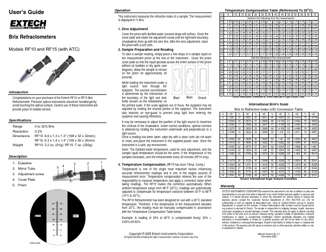
23 0.21 0.21 0.22 0.22 0.23 0.23 0.23 0.23 0.24 0.24 0.24 0.24 0.23 0.22
24 0.28 0.29 0.29 0.30 0.30 0.31 0.31 0.31 0.31 0.31 0.32 0.32 0.31 0.31
25 0.35 0.36 0.37 0.38 0.38 0.39 0.39 0.40 0.40 0.40 0.40 0.40 0.39 0.39
It may be necessary to adjust the position of the light source to maximize the contrast of the shadowline. Under normal conditions, optimal contrast is obtained by holding the instrument underneath and perpendicular to a light source. Once a reading has been taken, wipe dry with a clean cloth (do not wash or rinse) and place the instrument in the supplied plastic case. Store the instrument in a safe, dry environment.
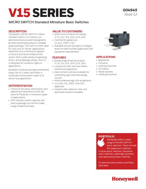
美国海利威尔公司V15系列微型基本开关说明书
V15 SERIESMICRO SWITCH Standard Miniature Basic Switches004945Issue 12DESCRIPTIONHoneywell’s MICRO SWITCH V-Basic Standard Switch, V15 Series is anelectromechanical switch designed to provide outstanding value in a reliable global package. This switch is often ideal for “low-cost-of-failure” applications, where the cost is minimal to replace or service any failure related to the switch. With a wide variety of operating forces, and amperage ratings, the V15 is designed for numerous types of applications.Available in both pin plunger and levered styles, the V15 Series also offers a multitude of termination styles to fit almost any application.DIFFERENTIATION• Choice of actuation, termination, and operating characteristics that can allow for flexibility in numerous types of applications• With a broad current capacity, one switch package can control a wide range of electrical loadsAPPLICATIONS• Appliances • Furnaces• Gaming machines • Ice makers • Power washers • Vending machinesVALUE TO CUSTOMERS• Wide choice of electrical ratings: 0.1 A, 5 A, 10 A, 16 A, 22 A, 26 A • Certified for global use: UL/cUL, ENEC, CQC• Available with pin plungers or integral levers to meet multiple application and equipment requirementsFEATURES• Broad range of electrical loads: 0.1 A, 5 A, 10 A, 16 A, 22 A, 26 A • Long service life: over one million mechanical operations• Gold contacts are also available for controlling logic level/low energy circuits• World-wide package size acceptance • UL/CSA, cUL, ENEC, and CQC approvals• Variants with cadmium-free and optimized contacts availableHoneywell offers a wide range of MICRO SWITCHthe large basic switches,Sensing and Internet of Things 3V15S05 PRODUCT NOMENCLATURE V15Switch TypeTemperatureGradeSLeverPositionElectrical Rating05V15 Series Standard Basic SwitchTerminal TypeCircuit Code—ZAOperating Force(at pin plunger max)200Mounting HolesKALever Type06Special DesignatorC—Housing Type1V15T10 PRODUCT NOMENCLATUREV15Switch TypeTemperatureGradeTLever PositionElectrical Rating10V15 Series Standard Basic SwitchTerminal TypeCircuit Code—ZAOperating Force(at pin plunger max)200Mounting HolesKALever Type06A special designator letter is used only when there is a special modificationto the switch.Review Product Specification to determine the exact differences. Below is an example.Special DesignatorC—Housing Type1V15H16/T16/T22/H22/T26 PRODUCT NOMENCLATURE V15Switch TypeTemperatureGradeHLever PositionElectrical Rating16V15 Series Standard Basic SwitchTerminal TypeCircuit Code—ZAOperating Force(at pin plunger max)200Mounting HolesKALever Type06Special DesignatorC—Housing Type1PinPlunger4 ShortStraightLeverStandardStraightLeverSensing and Internet of Things 5LongStraightLeverSimulatedRoller6 ShortRollerLeverSensing and Internet of Things 7RollerLever8 Sensing and Internet of Things 9MOUNTING DIMENSIONSFIGURE 1. V15 SERIES STANDARD SWITCH DIMENSIONSFIGURE 2. V15 SERIES METRIC MOUNTING HOLE DIMEN-SIONS FOR Ø 3 MM PINS OR SCREWSMetric mounting for Ø 3 mm pins or screws Ø 3,10 mm +0,10 mm/-0,05 mm 10,3 m m ±0,1 m m Ø 0.12 in +0.004 in/-0.002 in mounting holeFIGURE 3. V15 SERIES USA MOUNTING HOLE DIMENSIONS FOR #4 SCREWSUS mounting for #4 screws - K Designator Ø 2,90 mm +0,10 mm/-0,05 mm10,3 m m ±0,1 m m Ø 0.11 in +0.004 in/-0.002 in mounting holeFIGURE 4. V15 SERIES HOUSING DIMENSIONS10 Sensing and Internet of Things 1112 STANDARD LEVER OPTIONS • DIMENSIONSFIGURE 19. V15 SERIES A01/STRAIGHT SHORT LEV erFIGURE 20. V15 SERIES A02/STANDARD STRAIGHT LEVERFIGURE 21. V15 SERIES A03/LONG STRAIGHT LEVERFIGURE 22. V15 SERIES A04/SIMULATED ROLLER LEVERFIGURE 23. V15 SERIES A05/SHORT ROLLER LEVERFIGURE 24. V15 SERIES A06/ROLLER LEVERNOTE: These dimensions apply for the “A” lever position. For the “B” leverposition, please add 5,7 mm [0.224 in].Position APosition BWARRANTY/REMEDYHoneywell warrants goods of its manufacture as being free of defective materials and faulty workmanship during the applicablewarranty period. Honeywell’s standard product warranty applies unless agreed to otherwise by Honeywell in writing; please refer to your order acknowledgment or consult your local sales office for specific warranty details. If warranted goods are returned to Honeywell during the period of coverage, Honeywell will repair or replace, at its option, without charge those items that Honeywell, in its sole discretion, finds defective. The foregoing is buyer’s sole remedy and is in lieu of all other warranties, expressed or implied, including those of merchantability and fitness for a particular purpose. In no event shall Honeywell be liable for consequential, special, or indirect damages.While Honeywell may provide application assistance personally, through our literature and the Honeywell web site, it is buyer’s sole responsibility to determine the suitability of the product in the application.Specifications may change without notice. The information we supply is believed to be accurate and reliable as of this writing.However, Honeywell assumes no responsibility for its use.004945-12-EN | 12 | 08/20© 2019 Honeywell International Inc. All rights reserved.m WARNINGIMPROPER INSTALLATION• Consult with local safety agenciesand their requirements whendesigning a machine-control link, interface and all control elements that affect safety.• Strictly adhere to all installationinstructions. Failure to comply with theseinstructions could result in death or serious injury.m WARNINGMISUSE OFDOCUMENTATION•The information presented in this product sheet is for reference only. Do not use this document as a product installation guide.•Complete installation, operation, and maintenance information is provided in the instructions supplied with each product.Failure to comply with theseinstructions could result in death or serious injury.HoneywellSensing and Internet of Things 830 East Arapaho Road Richardson, TX FOR MORE INFORMATIONHoneywell Sensing and Internet of Things services its customers through a worldwide network of sales offices and distributors. For application assistance, current specifications, pricing, or the nearest Authorized Distributor, visit or call:USA/Canada +302 613 4491Latin America +1 305 805 8188Europe +44 1344 238258Japan +81 (0) 3-6730-7152Singapore +65 6355 2828Greater China+86 4006396841RELATED DOCUMENTATIONThe following associated literature is available on the Honeywell web site at :• Installation instructions• Product part listing/nomenclature tree• Product application-specific information– Application note: Electronic sensorsand eectromechanical switches in valves and flow meters – Application note: Electronic sensorsand MICRO SWITCH switches in industrial air compressors – Application note: Sensors andswitches for potential HVAC/R applications – Application note: Sensors andswitches for valve monitors and valve indicators – Application note: Sensors andswitches in sanitary valves – Case study: Switching it up– Technical bulletin: Applying precision switches。
宝马VO-list
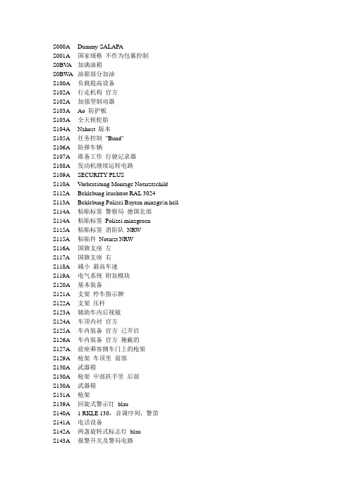
S000A Dummy-SALAPAS001A 国家规格不作为包裹控制S0BV A 加满油箱S0BW A 油箱部分加油S100A 负载提高设备S102A 行走机构官方S102A 加强型制动器S103A Ao 防护板S103A 全天候轮胎S104A Nahost 版本S105A 任务控制"Bund"S106A 防弹车辆S107A 准备工作行驶记录器S108A 发动机继续运转电路S109A SECURITY PLUSS110A Vorbereitung Montage NotarztschildS112A Beklebung leuchtrot RAL 3024S113A Beklebung Polizei Bayern minzgrün hell S114A 粘贴标签警察局德国北部S114A 粘贴标签Polizei minzgruenS115A 粘贴标签消防队NRWS115A 粘贴件Notarzt NRWS116A 国旗支座左S117A 国旗支座右S118A 减小最高车速S119A 电气系统附加模块S120A 基本装备S121A 支架停车指示牌S122A 支架压杆S123A 辅助车内后视镜S124A 车顶内衬官方S125A 车内装备官方已开启S126A 车内装备官方掩蔽的S127A 前座乘客侧车门上的枪架S129A 枪架车顶里前部S130A 武器箱S130A 枪架中部扶手里后部S130A 武器箱S131A 枪架S139A 回旋式警示灯blauS140A 1 RKLE 130,音调序列,警笛S141A 电话设备S142A 两盏旋转式标志灯blauS143A 报警开关及警局电路S144A RKLE 可拆卸电话设备警方S145A 报警开关带消防队电路S146A 辅助电源供应S147A 旋转式标志灯可拆卸S148A iDrive 操作特殊信号装置S149A 双闪光灯可拆下S150A 装配RTK-4 带送受话器S151A Sondersignalanlage Hella RTK-6S152A 特殊信号装置S153A 天窗,无特殊信号装置S155A 装配Top-4 带送受话器S159A 装配空气动力装置S160A 装配Becker 信号装置LU 322S161A 废气排放标准EU5S162A 准备工作装配MartinshornS163A 废气排放标准EU6S163A BMW 柴油发动机带蓝色性能S165A 惯性定时开关头部安全气囊惰性化S166A 准备工作停车信号后部杂物架S167A 废气标准欧规4S168A 减少废气排放EU 2S169A 废气触媒转换器柴油机S169A 减少废气排放EU 3S170A 安装FuG AEG Teledux 预留接口S170A Vorb. Fug 2m-4m Bd,AEG(BKA)S171A 准备工作安装Fug AscomS172A 准备工作Fug 7B 完整手套箱S172A 匹配含乙醇的燃油S173A 准备工作Fug 7B/8B/9C 手套箱S174A Vorb. Fug 8B/9C 手套箱S175A Vorb. FuG 8B/9CS176A Vorb. Fug 8B/9C 降下S178A 支架便携式收音机S179A 刺激性毒气传感器S180A 准备工作车顶天线S180A 车顶天线S181A 准备工作/装配车尾天线S182A 灭火设备S183A 准备工作用于主动防卫S184A 紧急出口挡风玻璃S185A 全套汽车已开启S186A 警车已伪装S187A 底板护件S188A 车门窗玻璃可降低前部左侧+ 后侧S189A 车门窗玻璃可降低前部+ 后部S190A 双向通话装置S191A 车门窗玻璃可降低前部右侧S192A 车门窗玻璃可降低前部左侧S193A 取消加热式前车窗和侧车窗S194A 遥控起动装置S195A 辅助地面装甲S196A 燃油箱制止排放的S197A 声音和光报警装置S198A 辅助新鲜空气通风装置S199A 损坏废气触媒转换器S199A 车型使用含铅燃油S1A1A Ausst. Kraftstoffe mit Verkokungsneigung S1AAA 55 kW 发动机型号S1AEA Flexible FuelS1AFA 大号燃油加注管S1AGA 更大的燃油箱S1AKA 外侧燃油滤清器S1CAA 选择COP 相关车辆S1CBA CO2 范围S1CCA Auto start/stop functionS1CDA Brake Energy RegenerationS200A 损坏废气触媒转换器S200A 柴油微粒过滤器S201A 菜籽油甲基酯适用性(RME)S202A 带手动换档模式的自动变速箱S203A 四轮驱动S204A 驱动设计用于出口S204A 更短的HAG传动比S205A 自动变速箱S206A Sequential manual transmission (SMG)S207A 第6 档位变速箱S208A 无动态稳定控制IIIS209A 可锁式差速器S210A 动态稳定控制S211A 动态稳定控制S212A 无防抱死系统S212A 装备制动系统国家S213A 下坡行驶控制(下坡行驶辅助)S213A 自动稳定控制S214A 自动稳定控制系统(ASC+T)S215A 助力转向,与转速相关S216A 助力转向电子伺服转向系统S217A 方向盘皮革S217A D SteeringS218A 跑车皮方向盘IIS219A 跑车皮方向盘380 mmS220A 高度调节S221A 2 车桥高度调节包括电子减震控制系统S222A 电子减震控制系统S223A 电子减震控制系统S224A 行驶动态控制S225A 标准底盘S226A 运动型底座调整S227A 运动型底盘+深度调节+高度调节S228A 运动型底盘调整加S228A 舒适型底盘S229A 动态行驶稳定装置S230A 附加范围欧规专用S230A 运动型底盘及深度调节S231A 取消250 km/h 限制S232A BMW 轻质合金轮辋径向轮幅50S233A 挂车负荷升高S234A 挂车挂钩高度可调S235A 可拆卸挂车挂钩S236A BMW 轻质合金轮辋带轮胎混装S238A BMW 轻质合金轮辋双轮幅93S239A BMW 轻质合金轮辋多轮幅94S240A 方向盘皮革安全气囊S241A 驾驶员和前座乘客安全气囊S242A 方向盘安全气囊S243A 安全气囊前座乘客S244A 转向柱手动可调S245A 转向柱电动可调S246A 转向柱手动可调S247A 方向盘轴向调整机械的S248A 方向盘加热S249A 多功能方向盘S250A 多功能方向盘S250A 侧面安全气囊为后座区乘客设置S251A 轮胎失压显示S252A 主动式护膝驾驶员/ 前乘客S253A 真皮方向盘Cooper SS253A 多功能方向盘木S254A 跑车方向盘带木质轮缘S254A 方向盘木S255A 跑车皮革方向盘安全气囊S256A 跑车/MFL方向盘/车速调节S257A 后部侧面安全气囊退出工作S258A 轮胎带紧急运行特性S259A 无侧面安全气囊S260A 侧面安全气囊为驾驶员/前座乘客设置S261A 侧面安全气囊为后座区乘客设置S262A ITS 头部安全气囊S263A 在后座区的ITS 头部安全气囊S263A 轻质合金轮辋及轮胎混装S264A BMW 轻质合金轮辋星形轮幅55S265A 轮胎压力监控(RDC)S266A BMW 轻质合金轮辋径向轮幅48S267A BMW 轻质合金轮辋星形轮幅49S268A BMW 轻质合金轮辋星形轮幅95S269A BMW 轻质合金轮辋径向轮幅32S270A 车轮带宽轮胎S271A BMW 轻质合金轮辋Z 线形S272A BMW 轻质合金轮辋Z 星形S273A BMW 轻质合金轮辋星形轮幅43S274A BMW 轻质合金轮辋双轮幅53S274A BMW 轻质合金轮辋平星样式S275A BMW 轻质合金轮辋镀铬的/Z 星形S276A BMW 轻质合金轮辋圆轮幅样式S277A BMW 轻质合金轮辋双轮幅S278A BMW 轻质合金轮辋带轮胎混装S278A BMW 轻质合金轮辋BMW 式样S279A BMW 轻质合金轮辋星形轮幅45S279A BMW 轻质合金轮辋无紧急运行特性S280A BMW 轻合金车轮轮辐式样S281A BMW 轻质合金轮辋镀铬的/圆轮幅S282A BMW 轻质合金轮辋运动轮幅样式II S283A BMW 轻质合金轮辋BMW 式样IIS284A BMW 轻质合金轮辋椭圆样式46S284A BMW 轻质合金轮辋BMW 式样S285A BMW 轻质合金轮辋BMW 式样S286A BMW 轻质合金轮辋BMW 式样S287A BMW 轻质合金轮辋星形轮幅64S288A BMW 轻质合金轮辋十字轮幅29S289A BMW 轻质合金轮辋BMW 式样S290A BMW 轻质合金轮辋星形轮幅44S291A BMW 轻质合金轮辋十字轮幅2部分S292A BMW 轻质合金轮辋十字轮幅29S293A BMW 轻质合金轮辋带紧急运行特性。
创新、发明与专利实务课后习题答案
专利制度的历史(一)1世界上第一部具有现代意义的专利法是()。
A、《物权法》B、《保险法》C、《垄断法》D、《竞争法》正确答案: C2根据2012年世界知识产权组织权威发布的报告,()成为专利申请第一大国。
A、美国B、日本C、澳大利亚D、中国正确答案: D3“专利制度就是在天才的火焰上倾倒利益之油”是谁的名言?()A、瓦特B、林肯C、爱迪生D、柯克正确答案: B4专利权起源于资本主义社会的财产权。
()正确答案:×5专利权在英国工业革命之前就已经正式确立。
()正确答案:√专利制度的历史(二)1根据国家统计局2004年数据显示,国内企业、个人专利申请集中领域不包括()。
A、食品B、服装C、软饮料D、汉字输入法正确答案: B2我国1985年颁布的《专利法》规定的专利垄断期限是()。
A、12年B、13年C、14年D、15年正确答案: D3VCD最早是由()发明制造的。
A、美国B、日本C、中国D、韩国正确答案: C4美国在本国公司申请了美国和加拿大的童锁专利后,要求进口彩电必须具备童锁功能。
()正确答案:×5在欧美发达国家,很多专利发明都用来设置贸易壁垒。
()正确答案:√专利制度的历史(三)1真空瓶在专利申请之初的目的是()。
A、教学实验B、工业发明C、盛放热水D、低温研究正确答案: D2日用拉链专利获得批准是在()。
A、1905年B、1914年C、1917年D、1920年正确答案: C3著名公司Thermos的设立与真空瓶专利的申请关系密切。
()正确答案:√4美国人吉德昂·逊德巴克于1917年提出了拉链的申请。
()正确答案:×专利制度的历史(四)1三点式汽车安全带的发明最早出现在()公司。
A、奔驰戴姆勒公司B、奔驰梅赛德斯公司C、沃尔沃公司D、大众公司正确答案: C2下列专利发明出现在19世纪的是()。
A、吉列剃须刀B、瓦特蒸汽机C、膨胀螺钉D、三点式安全带正确答案: A3英国工程师瓦特发明了蒸汽机。
LG 液晶电视机 32LS3158-CB 使用说明书
• 向服务中心要求维修服务。不论电视机因何种方式损坏,如电源线或插头 损坏,液体流入或物体落入电视机内,电视机暴露在雨中或潮湿的地方后 无法正常使用,电视机跌落,都可以邀请维修。
重要预防措施
7
• 冷机状态下打开电视机时可能会出现些微“闪烁”,这是正常现象,电视 机没有故障。
• 长时间显示一个固定图像(如广播频道标识、屏幕菜单、电视游戏场景) 可能损伤屏幕,导致图像残留,这就是图像拖尾。 图像拖尾不会覆盖在电视机上。 避免观看一个固定图像超过一小时。 如果长时间使用4:3的画面比率观看电视,面板边缘可能发生图像拖尾。 这种现象也可能出现在第三方产品中,不能退换。
• 杂音 “破裂”声:观看电视或关闭电视机时,塑料因为温度和湿度的原因发热 收缩从而产生破裂声,这是会发生热变形的产品的普遍现象。 电路或面板的“嗡嗡”声:电路高速开关过程中产生的大量电流会导致低 频噪音,这种情况因产品不同而有所差异。 产生的杂音不影响电视机性能。
输入 / 快捷菜单 / AV 模式 /节目列表/ 喜爱节目/Simplink 28 基本功能设置介绍 图像设置 / 声音设置 / 搜台设置 / 时间设置 / 锁定 / 选项设置 / 客户支持
40 使用 USB 设备 41 浏览文件 42 影片列表 44 图片列表 46 音乐列表
48 观看 3D 影像注意事项 49 观看 3D 视频 49 3D 选项设置 50 3D 影像支持文件格式 50 HDMI-PC模式
• 请使用制造商指定配件或附件。
• 请由专业人员安装天线。 可能发生火灾或电击。
5~7 times
• 我们建议您在观看电视时最少与电视机保持屏幕对角线尺寸2到7倍的距离。
泽塔4多功能遥控器指南说明书
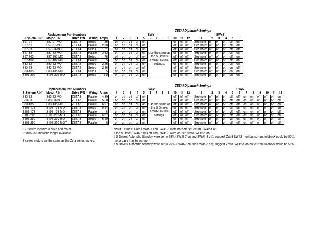
on off off off on
settings.
off off off See note1 off off on off on
on off on on off
off off off See note1 off off on on off
on on off on on
off off off See note1 off off on on on
on on on on on
off off off See note1 off off off off off on off on on off off
Note1: If the S Drive SW#1-7 and SW#1-8 were both off, set Zeta8 SW#2-1 off. If the S Drive SW#1-7 was off and SW#1-8 were on, set Zeta8 SW#2-1 on. If S Drive's Automatic Standby were set to 75% (SW#1-7 on and SW#1-8 off), suggest Zeta8 SW#2-1 on but current foldback would be 50%, motor case may be warmer. If S Drive's Automatic Standby were set to 25% (SW#1-7 on and SW#1-8 on), suggest Zeta8 SW#2-1 on but current foldback would be 50%.
8
S106-205-MO ZETA8 Parallel 6.97
S106-250-MO** ZETA8 Series 6.19
pro-face sp5000系列 硬件手册说明书

目录
SP5000-MM01-CS-PDF_O
安全信息 ....................................................................................................7 关于本书 ....................................................................................................8 概述......................................................................................................... 11
对于将本指南或其内容用作商业用途的行为,施耐德电气未授予任何权利或许可,但 以“原样”为基础进行咨询的非独占个人许可除外。
施耐德电气的产品和设备应由合格人员进行安装、操作、保养和维护。
由于标准、规格和设计会不时更改,因此本指南中包含的信息可能会随时更改,恕不 另行通知。
在适用法律允许的范围内,对于本资料信息内容中的任何错误或遗漏,或因使用此处 包含的信息而导致或产生的后果,施耐德电气及其附属公司不会承担任何责任或义 务。
标准主机模块 ................................................................................28 增强型主机模块............................................................................. 30 开放型主机模块............................................................................. 32 LED 指示 ......................................................................................34 显示模块 ............................................................................................35 精良显示模块 ................................................................................35 高级显示模块 ................................................................................39 LED 指示 ......................................................................................42 规格......................................................................................................... 44 一般规格 ............................................................................................44 电气规格....................................................................................... 44 环境规格....................................................................................... 46 结构规格....................................................................................... 47 功能规格 ............................................................................................49 显示规格....................................................................................... 49 存储器 ..........................................................................................51 时钟 .............................................................................................51 触摸屏 ..........................................................................................51 接口规格 ............................................................................................52 接口规格....................................................................................... 52 接口连接....................................................................................... 54 用于 COM1/COM2 的串行接口 (RS-232C 和 RS-422/RS485) .............................................................................................57 辅助输出/扬声器输出接口 (AUX) ....................................................59 DVI-D 输出接口.............................................................................60 尺寸......................................................................................................... 62 标准主机模块...................................................................................... 62 SP-5B00 ......................................................................................62 增强型主机模块 ..................................................................................63 SP-5B10 ......................................................................................63 开放型主机模块 ..................................................................................63
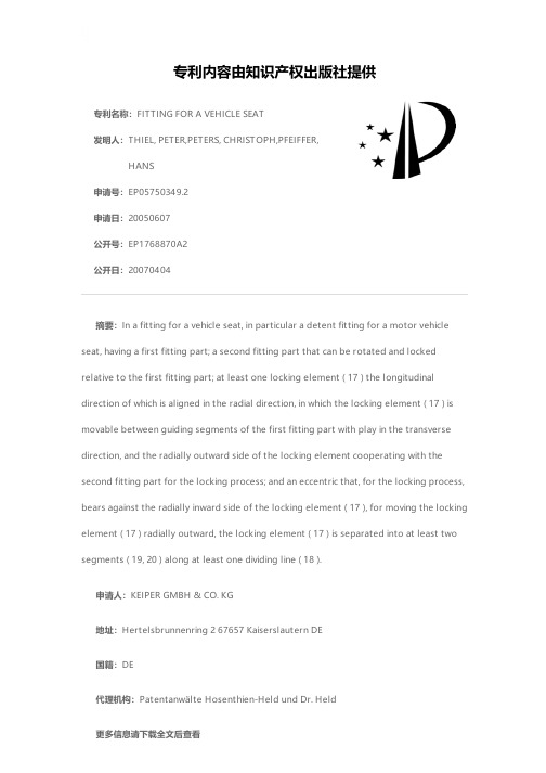
FITTING FOR A VEHICLE SEAT
艾迪菲斯ecb-500使用说明书
艾迪菲斯ecb-500使用说明书摘要:一、艾迪菲斯ecb-500 使用说明书简介1.产品背景2.适用人群3.功能特点二、说明书的使用方法1.阅读说明书的必要性2.说明书的内容结构3.注意事项三、ecb-500 的使用步骤1.准备工作2.设备连接3.功能操作四、常见问题及解决方法1.使用过程中的问题2.设备维护保养3.联系售后服务正文:艾迪菲斯ecb-500 使用说明书是一份详细介绍该产品的操作指南,对于正确使用该设备具有重要的参考价值。
本篇文章将为您概括说明书中的一些关键信息,帮助您更好地了解和使用艾迪菲斯ecb-500。
首先,让我们了解一下艾迪菲斯ecb-500 使用说明书的简介。
该产品背景部分介绍了艾迪菲斯ecb-500 的设计理念和应用领域。
适用人群部分则针对不同年龄、性别和身体状况的人群,阐述了ecb-500 的使用效果和适用性。
功能特点部分详细介绍了艾迪菲斯ecb-500 的各项功能和优势,如便携性、操作简便、性能稳定等。
接下来,我们来关注一下说明书的使用方法。
阅读说明书的必要性在于,它可以帮助您全面了解产品的功能和使用方法,避免因操作不当导致的设备损坏或人身安全问题。
说明书的内容结构通常包括产品介绍、使用方法、注意事项等部分。
在阅读过程中,您需要关注这些部分的内容,以确保正确使用ecb-500。
在了解说明书的使用方法后,我们来学习一下ecb-500 的使用步骤。
准备工作包括检查设备包装是否完好、配件是否齐全等。
设备连接部分则需要您按照说明书上的图示,正确连接设备各部件。
功能操作部分涉及到具体的操作步骤,您需要仔细阅读并按照要求进行操作。
最后,我们来了解一下常见问题及解决方法。
在使用过程中,可能会遇到一些问题,如设备无法正常启动、操作界面不灵敏等。
此时,您可以参考说明书上的解决方案,尝试解决问题。
同时,说明书还提供了设备维护保养的方法,以延长设备使用寿命。
如果您在使用过程中遇到无法解决的问题,可以联系售后服务,寻求专业帮助。
- 1、下载文档前请自行甄别文档内容的完整性,平台不提供额外的编辑、内容补充、找答案等附加服务。
- 2、"仅部分预览"的文档,不可在线预览部分如存在完整性等问题,可反馈申请退款(可完整预览的文档不适用该条件!)。
- 3、如文档侵犯您的权益,请联系客服反馈,我们会尽快为您处理(人工客服工作时间:9:00-18:30)。
大牌电商日报:Swatch上半财年销售额大跌12%
作者: 亿邦动力网来源: 亿邦动力网
【亿邦动力网讯】在这里,亿邦动力网将为你提供电商视角下的国际品牌
最新动向。
欢迎关注微信公众号“国际电商消息”(微信号:ECguoji),如有此方面信息欢迎联系heyang@。
瑞士名表品牌Swatch近年来也陷入了销售低迷期,在销售和盈利双重预警中披露了上半财年销售录得12%的同比跌幅。
而在香港零售市场不景气的情况下,韩国化妆品集团爱茉莉却逆势扩充,不禁让同行眼红。
此外,时尚服饰品牌
H&M和Superdry都发来了较好的业绩报告,前者6月销售额终于超预期,后者2016财年税前利润大涨14.6%。
1、Swatch上半财年销售盈利双重预警
瑞士钟表品牌Swatch Group AG(斯沃琪集团)日前表示,由于瑞士手表
最大出口市场——香港的持续萎靡,以及法国和瑞士两大欧洲奢侈品市场的疲软,公司的销售及盈利大幅下滑,集团股价在上周五盘中一度急挫14%。
据悉Swatch集团在销售和盈利双重预警中披露上半财年销售录得12%的
同比跌幅,从而导致营业利润和净利润均比去年同期减少了50%-60%,其中,净利润的跌幅远逊于市场预期的22%。
除了销售下滑之外,Swatch方面指出,
在第三方大幅削减订单的情况下保留员工、维持对新产品的投资和营销以及采取抵御性的涨价措施都对盈利产生压力。
2、韩国化妆品集团爱茉莉在港逆市扩充今年将新开10家店
尽管香港零售市场仍然低迷,但韩国化妆护肤品在这里似乎并没有收到影响。
日前,拥有雪花秀、LANEIGE(兰芝)等品牌的韩国化妆品集团
AMOREPACIFIC(爱茉莉)逆势扩充,计划在港新开10家新店。
管理层
表示,新店选址除了旅游区,亦会考虑在新界的居民区。
爱茉莉香港市务总监郑载欢表示,虽然香港零售市场充满挑战,但对韩国化妆品的影响有限,韩国化妆护肤产品在港仍受欢迎,上半年韩国化妆品出口至香港的货量有双位数增长。
其指出,集团旗下的香港业务上半年销售录得逆市可观的升幅,维持香港区业务全年仍有升幅的目标。
3、快时尚品牌H&M今年6月销售增长8% 超预期
全球第二大服装零售商H&M最新财报显示,今年6月,集团公司的含税销售按当地汇率计算实现了8%的增长,优于市场预期的7%。
此前,H&M集团曾指出,其6月1日-21日的销售增速为7%。
据悉,截至6月30日,H&M集团在全球设有4095间店铺,比去年同期的3642间净增了453间。
4、欧莱雅集团收购法国天然护肤品牌SGMB
法国美妆巨头欧莱雅集团(L’Oréal)近日宣布,已向法国家族经营的有机
护肤品供应商Rivadis Group要约收购后者旗下的温泉水疗度假村Sociétédes Thermes de Saint-Gervais-les-Bains及天然护肤品牌Saint-Gervais
Mont-Blanc(简称SGMB)。
目前,双方已进入排他性谈判阶段,交易细节暂未披露。
据美国WWD网站报道,Saint-Gervais Mont-Blanc的护肤产品配方为阿尔卑斯山最高峰-勃朗峰(Mont Blanc)的温泉水及天然高山植物萃取。
目前,其产品共六个系列,其中的防晒产品不含烃基苯甲酸酯或苯氧基乙醇。
5、时尚品牌Superdry年销售大增21% 今年在中国开3家店
在截至2016年4月30日的2016财年(53周)里,英国时尚服饰品牌Superdry(极度干燥)母公司Supergroup PLC税前利润大涨14.6%至7240万英镑,若以上一财年52周对比,Supergroup PLC税前利润则有16.3%的增幅至7350万英镑。
52周销售同比增长21.3% 至5.901亿英镑,而53周收入同比增幅为22.8%至5.975亿英镑。
根据数据显示,2016财年期内,Supergroup PLC的零售收入增幅达到24.5%,可比销售亦有11.3% 的增幅,其中,电商销售同比增长23.1%;批发收入同比增长14.2%,期内净增48间国际特许经营门店。
公司首席执行官Euan Sutherland对集团全年表现感到满意,并称在新市场美国和中国开局良好。
据悉,2016财年集团在美国市场亏损290万英镑,并计划2016年净增5间门店,而中国市场首店也于6月在上海开业,7月份计划在上海和北京各新增一店。
