78K0 KC2 Tutorial manual
NEC 78K 8-16位MCU选型手册
240 k
8-位 x 1
LVI
(7.62)
4
256
20-WLBGA
(2.1 x 2.6)
4 Flash √ 256 10 8 M, − 26 −/− 1 2
−
− − 1 16-位 x 1, − 1 − − − − − − − − − − − 4 − − 8 x 8 POC (2.1 V ± 0.1 V), 2.0 ~ 5.5 30-SSOP
8-位 x 4
16-位 x 2,
1
8-位 x 4
16 x 16 32 ÷ 16
√
−
1 − 1 16-位 x 2, − 1 1 − 1 − − 1 − − − − − 8 − − 16 x 16 POC, LVI
8-位 x 4
32 ÷ 16
√
选择指南 U17652CA5V0SG
1.8 ~ 5.5 30-SSOP (7.62)
POC: 上电清零电路 LVI: 低电压检测电路
8 Flash √ 512 20 8 M, − 23 −/− 1 4
16
768
240 k
24
1024
32
16 Flash √ 768 20 8 M, √ 31 −/− 1 4
24
1024
240 k
32
16
768
37
24
1024
32
16
768
41
24
1024
1.8 ~ 5.5 80-LQFP (12 x 12) 80-LQFP (14 x 14)
* 开发中
3
设备
存储器
时钟 I/O 总线
定时器
串行接口
MINICUBE2在78K0S微控制器上的片上调试
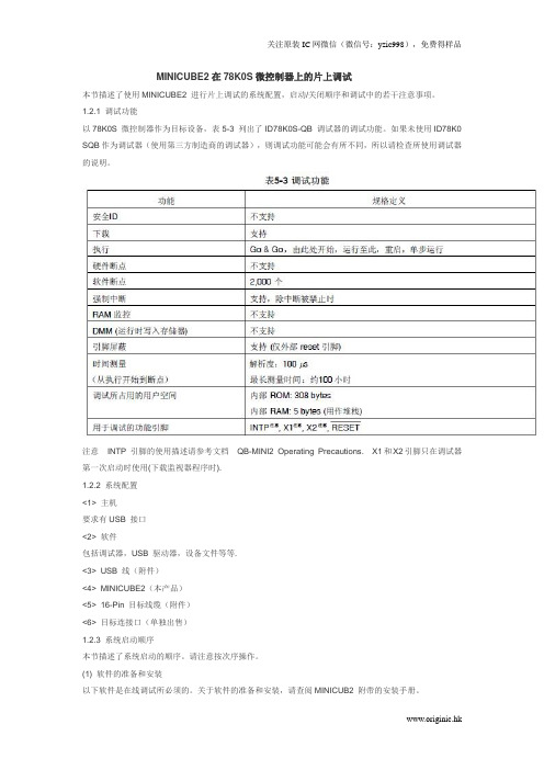
MINICUBE2在78K0S微控制器上的片上调试本节描述了使用MINICUBE2 进行片上调试的系统配置,启动/关闭顺序和调试中的若干注意事项。
1.2.1 调试功能以78K0S 微控制器作为目标设备,表5-3 列出了ID78K0S-QB 调试器的调试功能。
如果未使用ID78K0 SQB作为调试器(使用第三方制造商的调试器),则调试功能可能会有所不同,所以请检查所使用调试器的说明。
注意INTP 引脚的使用描述请参考文档-和X2引脚只在调试器第一次启动时使用(下载监视器程序时).1.2.2 系统配置<1> 主机要求有USB 接口<2> 软件包括调试器,USB 驱动器,设备文件等等.<3> USB 线(附件)<4> MINICUBE2(本产品)<5> 16-Pin 目标线缆(附件)<6> 目标连接口(单独出售)1.2.3 系统启动顺序本节描述了系统启动的顺序。
请注意按次序操作。
(1) 软件的准备和安装以下软件是在线调试所必须的。
关于软件的准备和安装,请查阅MINICUB2 附带的安装手册。
• 调试器• USB 驱动• 设备文件(如果使用第三方调试器,可能不需要)(2) 开关设置将模式选择开关设置为“M1”,电源选择开关则请查阅表5-4。
注意在USB 线连接状态时,请勿改变开关的设置。
注意最大允许电流100mA,所以请勿将MINICUBE2 连接到电流很大的目标系统上。
在MINICUBE2 与主机连通后,主机始终保持向MINICUBE2 供电。
(3) 连接目标系统MINICUBE2 到目标系统的连接如图5-14 所示。
在打开给目标系统的电源前连接。
(4) 连接USB 线缆请在目标系统上电之前,将MINICUBE2 连接到主机。
当电源选择开关打在“T”位置时,连接后模式灯为白色并开始闪烁。
当电源选择开关打在“3”或者“5”位置时,连接后模式灯点亮为白色。
78K0系列用户手册(指令集)
To our customers,Old Company Name in Catalogs and Other DocumentsOn April 1st, 2010, NEC Electronics Corporation merged with Renesas Technology Corporation, and Renesas Electronics Corporation took over all the business of both companies. Therefore, although the old company name remains in this document, it is a valid Renesas Electronics document. We appreciate your understanding.Renesas Electronics website: April 1st, 2010Renesas Electronics CorporationIssued by: Renesas Electronics Corporation ()Send any inquiries to /inquiry.Notice1. All information included in this document is current as of the date this document is issued. Such information, however, issubject to change without any prior notice. Before purchasing or using any Renesas Electronics products listed herein, please confirm the latest product information with a Renesas Electronics sales office. Also, please pay regular and careful attention to additional and different information to be disclosed by Renesas Electronics such as that disclosed through our website.2. Renesas Electronics does not assume any liability for infringement of patents, copyrights, or other intellectual property rightsof third parties by or arising from the use of Renesas Electronics products or technical information described in this document.No license, express, implied or otherwise, is granted hereby under any patents, copyrights or other intellectual property rights of Renesas Electronics or others.3. You should not alter, modify, copy, or otherwise misappropriate any Renesas Electronics product, whether in whole or in part.4. Descriptions of circuits, software and other related information in this document are provided only to illustrate the operation ofsemiconductor products and application examples. You are fully responsible for the incorporation of these circuits, software, and information in the design of your equipment. Renesas Electronics assumes no responsibility for any losses incurred by you or third parties arising from the use of these circuits, software, or information.5. When exporting the products or technology described in this document, you should comply with the applicable export controllaws and regulations and follow the procedures required by such laws and regulations. You should not use RenesasElectronics products or the technology described in this document for any purpose relating to military applications or use by the military, including but not limited to the development of weapons of mass destruction. Renesas Electronics products and technology may not be used for or incorporated into any products or systems whose manufacture, use, or sale is prohibited under any applicable domestic or foreign laws or regulations.6. Renesas Electronics has used reasonable care in preparing the information included in this document, but Renesas Electronicsdoes not warrant that such information is error free. Renesas Electronics assumes no liability whatsoever for any damages incurred by you resulting from errors in or omissions from the information included herein.7. Renesas Electronics products are classified according to the following three quality grades: “Standard”, “High Quality”, and“Specific”. The recommended applications for each Renesas Electronics product depends on the product’s quality grade, as indicated below. You must check the quality grade of each Renesas Electronics product before using it in a particularapplication. You may not use any Renesas Electronics product for any application categorized as “Specific” without the prior written consent of Renesas Electronics. Further, you may not use any Renesas Electronics product for any application for which it is not intended without the prior written consent of Renesas Electronics. Renesas Electronics shall not be in any way liable for any damages or losses incurred by you or third parties arising from the use of any Renesas Electronics product for an application categorized as “Specific” or for which the product is not intended where you have failed to obtain the prior written consent of Renesas Electronics. The quality grade of each Renesas Electronics product is “Standard” unless otherwiseexpressly specified in a Renesas Electronics data sheets or data books, etc.“Standard”: Computers; office equipment; communications equipment; test and measurement equipment; audio and visual equipment; home electronic appliances; machine tools; personal electronic equipment; and industrial robots.“High Quality”: Transportation equipment (automobiles, trains, ships, etc.); traffic control systems; anti-disaster systems; anti-crime systems; safety equipment; and medical equipment not specifically designed for life support.“Specific”: Aircraft; aerospace equipment; submersible repeaters; nuclear reactor control systems; medical equipment or systems for life support (e.g. artificial life support devices or systems), surgical implantations, or healthcareintervention (e.g. excision, etc.), and any other applications or purposes that pose a direct threat to human life.8. You should use the Renesas Electronics products described in this document within the range specified by Renesas Electronics,especially with respect to the maximum rating, operating supply voltage range, movement power voltage range, heat radiation characteristics, installation and other product characteristics. Renesas Electronics shall have no liability for malfunctions or damages arising out of the use of Renesas Electronics products beyond such specified ranges.9. Although Renesas Electronics endeavors to improve the quality and reliability of its products, semiconductor products havespecific characteristics such as the occurrence of failure at a certain rate and malfunctions under certain use conditions. Further, Renesas Electronics products are not subject to radiation resistance design. Please be sure to implement safety measures to guard them against the possibility of physical injury, and injury or damage caused by fire in the event of the failure of aRenesas Electronics product, such as safety design for hardware and software including but not limited to redundancy, fire control and malfunction prevention, appropriate treatment for aging degradation or any other appropriate measures. Because the evaluation of microcomputer software alone is very difficult, please evaluate the safety of the final products or system manufactured by you.10. Please contact a Renesas Electronics sales office for details as to environmental matters such as the environmentalcompatibility of each Renesas Electronics product. Please use Renesas Electronics products in compliance with all applicable laws and regulations that regulate the inclusion or use of controlled substances, including without limitation, the EU RoHS Directive. Renesas Electronics assumes no liability for damages or losses occurring as a result of your noncompliance with applicable laws and regulations.11. This document may not be reproduced or duplicated, in any form, in whole or in part, without prior written consent of RenesasElectronics.12. Please contact a Renesas Electronics sales office if you have any questions regarding the information contained in thisdocument or Renesas Electronics products, or if you have any other inquiries.(Note 1) “Renesas Electronics” as used in this document means Renesas Electronics Corporation and also includes its majority-owned subsidiaries.(Note 2) “Renesas Electronics product(s)” means any product developed or manufactured by or for Renesas Electronics.用户手册适用于78K/0系列78K/0系列指令©NEC Electronics China 2007日本印制文档编号.U12326CA4V0UM00(第四版)发行日期2007年7月NCP(K)[备忘录]用户手册U12326CA4V0UM 2CMOS设备的注释①ESD防护措施如果MOS设备周围有强电场,将会击穿氧化栅极,从而影响设备的运行。
KB78编程软件用户手册
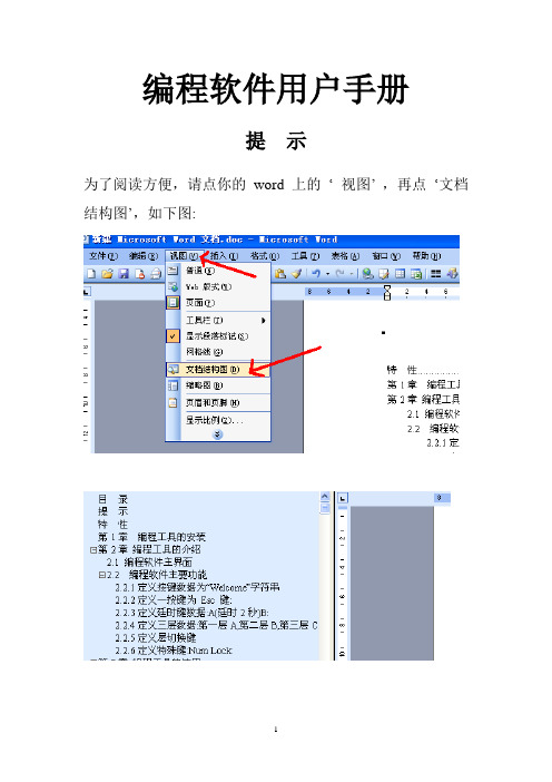
编程软件用户手册提示为了阅读方便,请点你的word上的…视图‟,再点…文档结构图‟,如下图:目录特性 (3)第1章编程工具的安装 (1)第2章编程工具的介绍 (5)2.1 编程软件主界面 (5)2.2 编程软件主要功能 (6)2.2.1定义按键数据为“Welcome”字符串 (7)2.2.2定义一按键为Esc 键: (9)2.2.3定义廷时键数据:A(廷时2秒)B: (10)2.2.4定义三层数据:第一层A,第二层B,第三层C: (11)2.2.5定义层切换键 (13)2.2.6定义特殊键:Num Lock: (14)第3章编程工具的使用 (16)3.1 利用鼠标编程 (17)3.2利用软键盘编程 (18)3.3 利用外接键盘编程 (19)3.4 编程数据的保存和读写 (21)3.5如何将定义好的键盘编码写进另一个键盘 (21)3.5.1.从已编程好的POS键盘中直接读出 (21)3.5.2从已保存好的定义文件中读出 (21)第4章电子键盘锁的编程 (22)4.1步骤一 (22)4.2步骤二 (23)4.3步骤三 (24)4.4键盘锁层数据的编程 (24)第5章DOS编程 (28)5.1 DOS版本编程软件界面介绍 (28)5.2 DOS编程软件操作指令介绍 (29)5.3 ASCⅡ码编程模式 (29)5.4扫描码编辑模式 (30)5.5特殊功能键编程 (31)5.5.1定义一个特殊的延时符 (31)5.5.2多层键的定义 (31)5.5.3 定义Caps lock、Num lock、Scroll lock键 (31)5.6键盘参数配置 (31)5.7从已保存好的定义文件编程 (32)特性●编程所有的键,包括副盘区,Shift,Ctrl,Alt,Esc,F1,L-Win,Power等。
●一共有78个可编程键。
●不需电池,数据永久保存。
●不需专用编程工具。
●每个键最多可编程255个字符。
●提供键盘嵌入功能,在接标准键盘与不接标准键盘的情况下都能正常作用。
78K0单片机C语言教程共159页

XT2 32kHz
XT1
(3)高速内置时钟 78K0内置8MHz时钟,如无特殊要求,可利用内置时钟。
78F0547D单片机时钟的控制:
①主时钟 通过执行STOP指令或设置主OSC控制寄存器(MOC)和处理器时钟控制寄存器 (PCC),可停止振荡。
②子时钟 通过设置处理器时钟控制寄存器(PCC)和时钟工作模式选择寄存器(OSCCTL)可 停止振荡。
单片机的发展历史
➢第一代:七十年代后期, 4 位逻辑控制器件发展到 8 位。 NMOS 工艺(速度低,功耗大、集成度低)。代表产品: MC6800 和 Intel 8048
➢第二代:八十年代初, CMOS 工艺,并逐渐被高速低功耗 的 HMOS 工艺代替。代表产品: MC146805 和 Intel 8051
课堂实施方案
主动提问题讨论,每人20个,每个1分
单片机应用系统硬件组成
数字量检 测
光电隔离
单
模拟量检 测
A/D转换
I/O
扩
片
开关量检 测
光电隔离
展
机
开关量控 制
光电隔离
D/A转换 I/O接口 显示器
键盘
伺服驱动 输出
通用外设
NEC单片机教学实验仪简介
1 实验仪外观、布局和图纸
CAN总线 包含SJA1000和 CTM1050T芯片
③高速内置时钟 通过执行STOP指令或设置内置振荡器模式寄存器(RCM),可停止振荡。
✓ 主时钟/子时钟/高速内置时钟3者只能选择其一工作,其余2个要停止。
④低速内置时钟(看门狗定时器(WDT)所用的240kHz时钟信号) RESET释放后,低速内置振荡器开始工作。若Option byte中设定了“低速内置 振荡器可以使用软件停止”,那么可以通过设置内置振荡器模式寄存器(RCM)来 停止振荡。
NEC的设备文件
CUSTOMER NOTIFICATIONDevice Files for 78K0/KB2, 78K0/KC2, 78K0/KD2,78K0/KE2, 78K0/KF2DF780547 (V2.21)User’s ManualBe sure to read this document before using the product.ZUD-CD-08-0055 (1/11)April 14, 2008Yoshinari Ando, Team Manager Development Tool Solution GroupMultipurpose Microcomputer Systems DivisionMicrocomputer Operations Unit NEC Electronics CorporationCONTENTS1. OUTLINE (3)2. PACKAGE CONTENTS (3)3. USER ENVIRONMENT (6)4. SUPPORTED DEVELOPMENT TOOLS AND VERSIONS (6)5. INSTALLATION (7)6. USAGE (7)7. DEFAULT LINK DIRECTIVE INFORMATION (8)8. REVISIONS FROM V2.20 TO V2.21 (11)1. OUTLINEA device file is a binary file that contains device-dependent information and is prepared for each device model or for each product in the same series.Device files are commonly used with development tools (such as assemblers, compilers and debuggers). Employing device files enables generation and debugging of device-unique codes. In addition, when developing applications, the special function register (SFR) names unique to the device can be used directly for programming.The DF780547 contains device files required for developing applications using the 78K0/KB2, 78K0/KC2, 78K0/KD2, 78K0/KE2, or 78K0/KF2.2. PACKAGE CONTENTSThe device files included in this product and the corresponding devices are as follows.Table 2-1. Package Contents (1/4)Type Generic NameDevice File NameCorresponding Device NamePin Count Device SpecificationNameVersionDF050030.78KμPD78F0500 μPD78F0500A μPD78F0500A(A)F050030 V2.21DF050130.78K μPD78F0501 μPD78F0501A μPD78F0501A(A)F050130 V2.21DF050230.78K μPD78F0502 μPD78F0502A μPD78F0502A(A)F050230 V2.21DF050330.78K μPD78F0503 μPD78F0503A μPD78F0503A(A) μPD78F0503D μPD78F0503DA30F050330 V2.21DF050036.78K μPD78F0500 μPD78F0500A μPD78F0500A(A)F050036 V2.21DF050136.78K μPD78F0501 μPD78F0501A μPD78F0501A(A)F050136 V2.21DF050236.78K μPD78F0502 μPD78F0502A μPD78F0502A(A)F050236 V2.21Device file78K0/KB2DF050336.78K μPD78F0503 μPD78F0503A μPD78F0503A(A) μPD78F0503D μPD78F0503DA36 F050336 V2.21Type Generic NameDevice File NameCorresponding Device NamePin Count Device SpecificationNameVersionDF051138.78KμPD78F0511 μPD78F0511A μPD78F0511A(A)F051138 V2.21DF051238.78K μPD78F0512 μPD78F0512A μPD78F0512A(A)F051238 V2.21DF051338.78K μPD78F0513 μPD78F0513A μPD78F0513A(A) μPD78F0513D μPD78F0513DA38F051338 V2.21DF051144.78K μPD78F0511 μPD78F0511A μPD78F0511A(A)F051144 V2.21DF051244.78K μPD78F0512 μPD78F0512A μPD78F0512A(A)F051244 V2.21DF051344.78K μPD78F0513 μPD78F0513A μPD78F0513A(A) μPD78F0513D μPD78F0513DA44 F051344 V2.21DF051148.78K μPD78F0511 μPD78F0511A μPD78F0511A(A)F051148 V2.21DF051248.78K μPD78F0512 μPD78F0512A μPD78F0512A(A)F051248 V2.21DF051348.78K μPD78F0513 μPD78F0513A μPD78F0513A(A)F051348 V2.21DF051448.78K μPD78F0514 μPD78F0514A μPD78F0514A(A)F051448 V2.21Device file78K0/KC2DF051548.78K μPD78F0515 μPD78F0515A μPD78F0515A(A) μPD78F0515D μPD78F0515DA48 F051548 V2.21Type Generic NameDevice File NameCorresponding Device NamePin Count Device SpecificationNameVersionDF052152.78KμPD78F0521 μPD78F0521A μPD78F0521A(A)F052152 V2.21DF052252.78K μPD78F0522 μPD78F0522A μPD78F0522A(A)F052252 V2.21DF052352.78K μPD78F0523 μPD78F0523A μPD78F0523A(A)F052352 V2.21DF052452.78K μPD78F0524 μPD78F0524A μPD78F0524A(A)F052452 V2.21DF052552.78K μPD78F0525 μPD78F0525A μPD78F0525A(A)F052552 V2.21DF052652.78K μPD78F0526 μPD78F0526A μPD78F0526A(A)F052652 V2.2178K0/KD2DF052752.78K μPD78F0527 μPD78F0527A μPD78F0527A(A) μPD78F0527D μPD78F0527DA52F052752 V2.21DF053164.78K μPD78F0531 μPD78F0531A μPD78F0531A(A)F053164 V2.21DF053264.78K μPD78F0532 μPD78F0532A μPD78F0532A(A)F053264 V2.21DF053364.78K μPD78F0533 μPD78F0533A μPD78F0533A(A)F053364 V2.21DF053464.78K μPD78F0534 μPD78F0534A μPD78F0534A(A)F053464 V2.21DF053564.78K μPD78F0535 μPD78F0535A μPD78F0535A(A)F053564 V2.21Device file78K0/KE2 DF053664.78K μPD78F0536 μPD78F0536A μPD78F0536A(A)64 F053664 V2.21The Device Specification Name is the character string specified as “-c device specification name ” (device type specification option), “#pragma pc(device specification name)” in C source in the CC78K0 (C compiler), and “$PROCESSOR(device specification name)” in assembler source in the RA78K0 (assembler).3. USER ENVIRONMENTLike development tools, device files are available for Windows.The user environment for device files depends on the environment for the development tools to be used.4. SUPPORTED DEVELOPMENT TOOLS AND VERSIONSThe versions of NEC Electronics development tools for the 78K0/KB2, 78K0/KC2, 78K0/KD2, 78K0/KE2 and 78K0/KF2, supported by the DF780547, are shown below. Use these tools in the following combinations.Table 4-1. Supported Development Tools and Versions (1)Tool UsedSupported Tool Version C compiler package CC78K0 V3.70 Assembler package RA78K0 V3.80 Integrated debugger ID78K0-QBV2.94 System simulator SM+ for 78K0 (instruction simulation version)V1.10System simulator SM+ for 78K0/Kx2 (instruction/peripheral simulation version) V1.10Type Generic NameDevice File NameCorresponding Device NamePin Count Device SpecificationNameVersionDF053764.78KμPD78F0537 μPD78F0537A μPD78F0537A(A) μPD78F0537D μPD78F0537DAF053764 V2.21DF054480.78K μPD78F0544 μPD78F0544A μPD78F0544A(A)F054480 V2.21DF054580.78K μPD78F0545 μPD78F0545A μPD78F0545A(A)F054580 V2.21DF054680.78K μPD78F0546 μPD78F0546A μPD78F0546A(A)F054680 V2.21Device file78K0/KF2DF054780.78K μPD78F0547 μPD78F0547A μPD78F0547A(A) μPD78F0547D μPD78F0547DA80F054780 V2.21Table 4-2. Supported Development Tools and Versions (2)Tool Used Supported Tool VersionC compiler package CC78K0 V4.00 and laterAssembler package RA78K0 V4.01 and laterIntegrated debugger ID78K0-QB V3.00 and laterSystem simulator (SM+ for 78K0 instruction simulation version) Under developmentSystem simulator SM+ for 78K0/Kx2 (instruction/peripheral simulation version) Under developmentRemark When using the DF780547 with the QB-78K0KX2, use the QB-78K0KX2 with control codeF or later.5. INSTALLATIONInstall the device file using the following procedure.(1) Download the device file from the NEC Electronics website (Development Tools Downloadwebpage) to any folder.English version: /micro/en/ods/→ Click “Version-up Service”.Japanese version: /micro/ja/ods/(2) Start the device file installer Note from the Start menu.(3) Click the [Install] button.(4) Click the [Browse] button to specify the folder where the decompressed files are located.(5) The NECSETUP.INI file and _CSETUP.INI file are displayed in the file list of the dialog boxthat appears after step (4). Select either of the following files according to the language ofthe OS used.English version: _CSETUP.INI.NECSETUP.INI.Japaneseversion:(6) Follow the installation wizard to continue installation.Note The device file installer is automatically installed when an NEC Electronics development tool (CC78K0, RA78K0 or ID78K0-QB) is installed.6. USAGERefer to the user’s manual of each tool for details on how to use the device file.7. DEFAULT LINK DIRECTIVE INFORMATIONEach device has different ROM and RAM capacities. The assembler package has default linkdirective information necessary to relocate the user's program and data in the device file according to the ROM capacity and RAM capacity of each product.In order to change the setting of the default, the user should create a link directive for each target system according to the memory configuration of the actual target system using the assembler package (linker). Note that user's program, data, and stack may not be appropriately located in the default link directive information. This means, for example, that user's data and stack may be located overlapping the register bank area and the reserved area of the C compiler.The default link directive information depends on the device as shown below.The area name ROM and RAM are essential area names. All the code segments (CSEG) are relocated in the area name ROM area and all the data segments (DSEG) and bit segments (BSEG) are relocated in the area name RAM area unless otherwise specified explicitly in the MERGEstatement.Table 7-1. Default Link Directive Information (1/3)Generic Name Device Default Link Directive InformationμPD78F0500μPD78F0500A μPD78F0500A(A) MEMORY ROM: (00000H, 02000H) MEMORY RAM: (0FD00H, 00300H)μPD78F0501μPD78F0501A μPD78F0501A(A) MEMORY ROM: (00000H, 04000H) MEMORY RAM: (0FC00H, 00400H)μPD78F0502μPD78F0502A μPD78F0502A(A) MEMORY ROM: (00000H, 06000H) MEMORY RAM: (0FB00H, 00500H)78K0/KB2μPD78F0503μPD78F0503A μPD78F0503A(A) μPD78F0503D μPD78F0503DA MEMORY ROM: (00000H, 08000H) MEMORY RAM: (0FB00H, 00500H)μPD78F0511μPD78F0511A μPD78F0511A(A) MEMORY ROM: (00000H, 04000H) MEMORY RAM: (0FC00H, 00400H)μPD78F0512μPD78F0512A μPD78F0512A(A) MEMORY ROM: (00000H, 06000H) MEMORY RAM: (0FB00H, 00500H)μPD78F0513μPD78F0513A μPD78F0513A(A) μPD78F0513D μPD78F0513DA MEMORY ROM: (00000H, 08000H) MEMORY RAM: (0FB00H, 00500H)78K0/KC2μPD78F0514μPD78F0514A μPD78F0514A(A) MEMORY ROM: (00000H, 0C000H) MEMORY IXRAM: (0F400H, 00400H) MEMORY RAM: (0FB00H, 00500H)Generic Name Device Default Link Directive Information 78K0/KC2 μPD78F0515μPD78F0515A μPD78F0515A(A) μPD78F0515D μPD78F0515DA MEMORY ROM: (00000H, 0F000H) MEMORY IXRAM: (0F000H, 00800H) MEMORY RAM: (0FB00H, 00500H)μPD78F0521μPD78F0521A μPD78F0521A(A) MEMORY ROM: (00000H, 04000H) MEMORY RAM: (0FC00H, 00400H)μPD78F0522μPD78F0522A μPD78F0522A(A) MEMORY ROM: (00000H, 06000H) MEMORY RAM: (0FB00H, 00500H)μPD78F0523μPD78F0523A μPD78F0523A(A) MEMORY ROM: (00000H, 08000H) MEMORY RAM: (0FB00H, 00500H)μPD78F0524μPD78F0524A μPD78F0524A(A) MEMORY ROM: (00000H, 0C000H) MEMORY IXRAM: (0F400H, 00400H) MEMORY RAM: (0FB00H, 00500H)μPD78F0525μPD78F0525A μPD78F0525A(A) MEMORY ROM: (00000H, 0F000H) MEMORY IXRAM: (0F000H, 00800H) MEMORY RAM: (0FB00H, 00500H)μPD78F0526μPD78F0526A μPD78F0526A(A) MEMORY ROM: (00000H, 08000H) MEMORY BANK0: (08000H, 04000H) MEMORY IXRAM: (0E800H, 01000H) MEMORY RAM: (0FB00H, 00500H) MEMORY BANK1: (18000H, 04000H) MEMORY BANK2: (28000H, 04000H)78K0/KD2μPD78F0527μPD78F0527A μPD78F0527A(A) μPD78F0527D μPD78F0527DA MEMORY ROM: (00000H, 08000H) MEMORY BANK0: (08000H, 04000H) MEMORY IXRAM: (0E000H, 01800H) MEMORY RAM: (0FB00H, 00500H) MEMORY BANK1: (18000H, 04000H) MEMORY BANK2: (28000H, 04000H) MEMORY BANK3: (38000H, 04000H) MEMORY BANK4: (48000H, 04000H) MEMORY BANK5: (58000H, 04000H)μPD78F0531μPD78F0531A μPD78F0531A(A) MEMORY ROM: (00000H, 04000H) MEMORY RAM: (0FC00H, 00400H)μPD78F0532μPD78F0532A μPD78F0532A(A) MEMORY ROM: (00000H, 06000H) MEMORY RAM: (0FB00H, 00500H)78K0/KE2μPD78F0533μPD78F0533A μPD78F0533A(A) MEMORY ROM: (00000H, 08000H) MEMORY RAM: (0FB00H, 00500H)Generic Name Device Default Link Directive InformationμPD78F0534μPD78F0534A μPD78F0534A(A) MEMORY ROM: (00000H, 0C000H) MEMORY IXRAM: (0F400H, 00400H) MEMORY RAM: (0FB00H, 00500H)μPD78F0535μPD78F0535A μPD78F0535A(A) MEMORY ROM: (00000H, 0F000H) MEMORY IXRAM: (0F000H, 00800H) MEMORY RAM: (0FB00H, 00500H)μPD78F0536μPD78F0536A μPD78F0536A(A) MEMORY ROM: (00000H, 08000H) MEMORY BANK0: (08000H, 04000H) MEMORY IXRAM: (0E800H, 01000H) MEMORY RAM: (0FB00H, 00500H) MEMORY BANK1: (18000H, 04000H) MEMORY BANK2: (28000H, 04000H) MEMORY BANK3: (38000H, 04000H)78K0/KE2μPD78F0537μPD78F0537A μPD78F0537A(A) μPD78F0537D μPD78F0537DA MEMORY ROM: (00000H, 08000H) MEMORY BANK0: (08000H, 04000H) MEMORY IXRAM: (0E000H, 01800H) MEMORY RAM: (0FB00H, 00500H) MEMORY BANK1: (18000H, 04000H) MEMORY BANK2: (28000H, 04000H) MEMORY BANK3: (38000H, 04000H) MEMORY BANK4: (48000H, 04000H) MEMORY BANK5: (58000H, 04000H)μPD78F0544μPD78F0544A μPD78F0544A(A) MEMORY ROM: (00000H, 0C000H) MEMORY IXRAM: (0F400H, 00400H) MEMORY LRAM: (0FA00H, 00020H) MEMORY RAM: (0FB00H, 00500H)μPD78F0545μPD78F0545A μPD78F0545A(A) MEMORY ROM: (00000H, 0F000H) MEMORY IXRAM: (0F000H, 00800H) MEMORY LRAM: (0FA00H, 00020H) MEMORY RAM: (0FB00H, 00500H)μPD78F0546μPD78F0546A μPD78F0546A(A) MEMORY ROM: (00000H, 08000H) MEMORY BANK0: (08000H, 04000H) MEMORY IXRAM: (0E800H, 01000H) MEMORY LRAM: (0FA00H, 00020H) MEMORY RAM: (0FB00H, 00500H) MEMORY BANK1: (18000H, 04000H) MEMORY BANK2: (28000H, 04000H) MEMORY BANK3: (38000H, 04000H)78K0/KF2μPD78F0547μPD78F0547A μPD78F0547A(A) μPD78F0547D μPD78F0547DA MEMORY ROM: (00000H, 08000H) MEMORY BANK0: (08000H, 04000H) MEMORY IXRAM: (0E000H, 01800H) MEMORY LRAM: (0FA00H, 00020H) MEMORY RAM: (0FB00H, 00500H) MEMORY BANK1: (18000H, 04000H) MEMORY BANK2: (28000H, 04000H) MEMORY BANK3: (38000H, 04000H) MEMORY BANK4: (48000H, 04000H) MEMORY BANK5: (58000H, 04000H)DF780547 (V2.21) User’s Manual ZUD-CD-08-0055 11/11In the above table, area RAM includes the SFR area (0FF00H to 0FFFFH). Note that, however, since the linker handles the SFR area as a reserved area, the segments (user’s data and stack) are not relocated in this area. For example, the result for “MEMORY RAM: (0FB00H, 00500H)” and “MEMORY RAM: (0FB00H, 00400H)” is the same.8. REVISIONS FROM V2.20 TO V2.21The following point has been corrected from DF780547 V2.20 to V2.21.•Correction of the following restrictionWhen IECUBE operates with a target voltage of less than 2.7 V, the reset may not be able to be released immediately after the debugger has started.。
78K0 微控制器体系结构
复位之后 硬件会自动设定该寄存器
用户程序开始 复位处理 正常运行(内置高速时钟工作)
CPU动作状态
设定2
设定3
MCU自动 设置Option Byte
软件初始化(寄存器设置)
设定4
Watchdog Timer设置
(1) 0080H/1080H
以低速内置振荡器时钟工作时 设置可使用或不可使用软件停止 看门狗定时器(WDT)时间间隔的设置 看门狗定时器(WDT)计数器的设置 计数器工作允许/禁止 看门狗定时器(WDT)开窗时间(Window Open Time)的设置
2 端口结构
所有的端口都带有输出锁存功能。
3 寄存器控制端口功能
端口的工作模式寄存器 名称为PMn,其中n=0-7,12,14。端口13只有输 出功能模式,不用选择。 模式寄存器对应位为1时选择输入模式,为0时选 择输出模式。 可由1 位或8 位存储器操作指令设置这些寄存器。
需要注意的是,当选择端口的可选功能时,也要 设定对应的端口工作模式。 比如串行口0需要使用P10和P11作为TXD0和RXD0 输出和输入串行信号,那么除了要选择端口1为 替换功能之外,还要设定P10和P11分别为输入和 输出模式。
1.2.3 特殊功能寄存器
从FFOOH到FFFFH总共256字节的区域分配给特殊 功能寄存器。 特殊功能寄存器可像通用寄存器那样用操作指令、 转移指令以及位操作指令进行操作。根据特殊功 能寄存器的类型不同,可操作的位单元也不同, 可以是1位、8位和16位。
78K0/Kx2微控制器
Option byte
μPD78F0547具有6K字节内部扩展数据空间,可 以作为数据区或程序执行区。
1.1.4 特殊功能寄存器
NEC端口功能
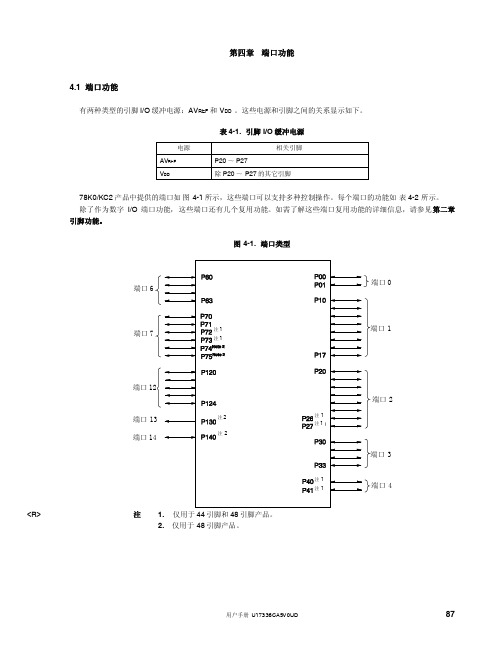
98
用户手册 U17336CA5V0UD
第四章 端口功能
图 4-9. P20 ~ P27 的框图
内部总线
输出锁存器 (P20~P27)
选择器
~
注
~ A/D 转换
<R>
注
38 引脚产品: 44 引脚和 48 引脚产品: P2: PM2: RD: 端口寄存器 2 端口模式寄存器 2 读信号
P20/ANI0 ~ P25/ANI5 P20/ANI0 ~ P27/ANI7
P1: PU1: PM1: RD:
端口寄存器 1 上拉电阻选择寄存器 1 端口模式寄存器 1 读信号
WR : 写信号
94
用户手册 U17336CA5V0UD
选择器
第四章 端口功能
图 4-6. P12 和 P15 的框图
内部总线
输出锁存器 (P12,P15)
复用功能
P1: PU1: PM1: RD:
WR : 写信号
96
用户手册 U17336CA5V0UD
选择器
第四章 端口功能
图 4-8. P16 和 P17 的框图
复用功能
内部总线
输出锁存器 (P16,P17)
复用功能
P1: PU1: PM1: RD:
端口寄存器 1 上拉电阻选择寄存器 1 端口模式寄存器 1 读信号
WR : 写信号
第9章 NEC78K0单片机常用的C语言扩展功能 20090416

第9章78K0单片机常用C语言扩展功能本章所描述的扩展功能是NEC78K0系列编译器CC78K0所特有,而在ANSI标准的C 语言中所没有的内容。
使用本编译器的扩展功能可以更有效的使用78K0系列的单片机,例如可缩短代码长度,提高运行速度等,但并非所有的扩展功能在任何情况下都是有效的,建议根据实际情况只使用那些可使程序优化的扩展功能。
9.1#pragma指令#pragma指令是符合ANSI标准的C语言所支持的预处理指令,根据#pragma后面的字符串,编译系统将按照特定的方式来翻译C语言的字符串和函数,如果编译系统不支持该#pragma指令,那么编译系统将忽略该#pragma指令而继续向下编译。
CC78K0编译系统通过支持的#pragma指令来完成扩展功能,在#pragma后面的关键字可以是大写字母,也可以是小写字母,以下是本章讲述的#pragma指令。
#pragma sfr在C语言中使用SFR->特殊功能寄存器的使用#pragma asm在C语言中插入汇编语句->在C语言中使用汇编语句#pragma vect#pragma interrupt在C语言中使用中断函数->中断功能的使用#pragma di #pragma ei 开中断(EI)和关中断(DI)的使用->开中断函数EI()和关中断函数DI()#pragma halt#pragma stop#pragma nop#pragma brkCPU控制指令->CPU控制指令#pragma access使用绝对地址->绝对地址存取指令#pragma rot使用旋转功能->循环移位#pragma mul使用乘法功能->乘法函数#pragma div使用除法功能->除法函数#pragma bcd十进制运算功能->BCD操作函数9.2特殊功能寄存器(SFR)的使用。
在微控制器中的特殊功能寄存器(SFR)是指完成一组特殊功能(如模式控制和各种外围功能控制)的寄存器,通过在文件的开头加上“#pragma sfr”的编译预处理语句,就可以在C 语言里象使用变量一样使用特殊功能寄存器了。
NCT-MINICUBE_v1.20A入门手册
NCT-MINICUBE 78K0快速入门手册VERSION V1.20NEC Electronics (China) Co.,LtdNEC Electronics Hong Kong Limited Date Published Feb,2006本商品、技术或软件的出口必须依据出口国的出口管理规章来进行。
不能违反当地法律。
· 本文档信息于2003年4月开始使用。
文档内容可能会作修改。
如果用户要进行实际的设计,请参阅最新出版的NEC数据表或数据手册等,以获取NEC半导体产品的最新规定。
并非所有产品在每个国家都能使用。
请联系NEC销售代理,了解使用信息和其他相关信息。
· 未经NEC的书面许可,不能对本文档复制。
本文档出现的任何错误,NEC不承担责任。
· 如果用户在使用本文档列出的NEC半导体产品或通过其他途径使用这些产品时,产生侵犯专利、版权以及其他侵犯第三方知识产权的行为,NEC不承担责任。
对于NEC及其他子公司的任何专利、版权以及其他知识产权,NEC没有以许可、明示、暗示以及其他任何方式授权。
· 文档中电路、软件和其他相关信息的描述,用来说明半导体产品操作和应用的例子。
客户在使用这些电路、软件和信息时负全责。
客户或第三方在使用这些电路、软件和信息时造成的损失,NEC不承担责任。
· NEC尽力提高半导体产品的质量、可靠性和安全性,但请客户理解错误是不可能完全避免的。
为了尽可能减少由于NEC半导体产品所带来的个人财产及人身安全(包括死亡)的风险,客户在设计过程中应加强安全措施,如容错、耐火性和自检等。
· NEC半导体产品分为以下三个质量等级:“标准”、“专业”、“特级”。
“特级”质量等级仅用于客户定制的半导体产品。
一种半导体产品的应用主要依据它的质量等级。
客户在使用某种半导体产品之前应先了解它的质量等级。
“标准”:计算机,办公设备,通信设备,测试设备,视频音频设备,家用电子产品,机械工具,个人电子设备和工业机器人“专业”:运输设备(汽车,火车,轮船等),交通控制系统,防灾系统,反犯罪系统,安全设备和医疗设备(不是专用于生命救护的设备)“特级”: 飞机,航空设备,水下中继器,核反应堆控制系统,生命救护系统和用于生命救护的医疗设备等。
NEC单片机开发环境建立说明

NEC单片机开发环境建立说明NEC 78Kx系列8bit MCU前言本文仅提供使用过程中的简单说明及注意事项,详细信息请参照“软件工具教学手册.pdf”。
初次使用NEC单片机的工程师建议两者都进行仔细阅读。
本文红色标注部分均为使用过程中的经验总结,请务必阅读,以免造成不必要的时间损失。
芯片型号说明:78K0S: 78K0S/KU1+ : uPD78F9202 uPD78F9201 uPD78F920078K0S/KY1+ : uPD78F9212 uPD78F9211 uPD78F921078K0S/KA1+ : uPD78F9222 uPD78F922178K0S/KB1+ : uPD78F9234 uPD78F923278K0:78K0/KB2 : uPD78F0503(D)A uPD78F0502A uPD78F0501A uPD78F0500A78K0/KC2 : uPD78F0515(D)A uPD78F0514AuPD78F0513(D)A uPD78F0512A uPD78F0511A78K0/KD2 : uPD78F0527(D)A uPD78F0526A uPD78F0525A uPD78F0524A uPD78F0523(D)A uPD78F0522A uPD78F0521A78K0/KE2 : uPD78F0537(D)A uPD78F0536A uPD78F0535A uPD78F0534A uPD78F0533(D)A uPD78F0532A uPD78F0531A78K0/KF2 : uPD78F0547(D)A uPD78F0546A uPD78F0545A uPD78F0544A注: 由于78K0系列型号及封装较多,客户选型时请参考选型手册,样片申请时烦请告知详细型号和封装。
参考文档软件工具教学手册.pdfQB-MINI2用户手册_英文.pdfQB-MINI2用户手册_中文.pdf目录1.编译软件PM plus安装2.DeviceFile 安装(设备文件安装)3.软件编译(PM plus使用说明)3.1进入PM plus3.2新建Workspace3.3 PM plus使用说明3.3.1 改变项目设置3.3.2 仿真调试选项3.3.3 编译选项确定3.3.4 快捷键简单说明3.3.5 生成文件信息说明3.3.6 建议4.硬件仿真[使用MINICUBE2]4.1 注意事项 **重要4.2 如何使用QB-MINI2仿真78K0s系列4.2.1 QB-MINI2硬件仿真程序安装及注意事项[78K0S]4.2.2 QB-MINI2硬件仿真连接说明[78K0S]4.2.3 片上调试占用软件资源说明[78K0S]4.2.4 经验之谈[78K0S]**重要4.3 如何使用QB-MINI2仿真78K0系列4.3.1 QB-MINI2硬件仿真程序安装及注意事项[78K0]4.3.2 QB-MINI2硬件仿真连接说明[78K0]4.3.3 片上调试占用软件资源说明[78K0]4.3.4 经验之谈[78K0]5.芯片烧录[使用MINICUBE2]5.1 MINICUBE2烧录软件QBP.exe 安装5.2 硬件连接5.3 MINICUBE2烧录软件QBP.exe 使用5.3.1 运行QBP.exe5.3.2 选择要烧录MCU对应的 PRM参数文件(烧录信息)5.3.3 78K0系列烧录通讯方式选择[78K0]5.3.4 载入烧录代码(*.hex文件)5.3.5 烧录快捷方式说明5.3.6 注意事项6.软件仿真(SM+)使用说明(无,请直接参照“软件工具教学手册.pdf”)7.代码生成器Applilet(无,帮助用户生成MCU资源初始化代码,较简单,直接使用)1. 编译软件PM plus安装返回目录源程序:ra78Kx: --安装程序ra78Kx 是用于NEC 78Kx 系列微处理器的汇编编译工具包。
78K0S78K0烧录接法
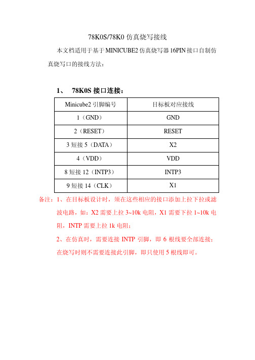
78K0S/78K0仿真烧写接线
本文档适用于基于MINICUBE2仿真烧写器16PIN接口自制仿真烧写口的接线方法:
接口连接::
1、78K0S接口连接
Minicube2引脚编号目标板对应接线
1(GND)GND
2(RESET)RESET
3短接5(DATA)X2
4(VDD)VDD
8短接12(INTP3)INTP3
9短接14(CLK)X1
备注:1、在目标板设计时,须在这些相应的接口添加上拉下拉或滤波电路,如:X2需要上拉3~10k电阻,X1需要下拉1~10k电
阻,INTP需要上拉1k电阻;
2、在仿真时,需要连接INTP引脚,即6根线要全部连接;
在烧写时则不需要连接此引脚,即只使用5根线即可。
接口连接((16pin):
2、78K0接口连接
Minicube2引脚编号目标板对应接线
1(GND)GND
2(RESET_OUT)RESET
3(RXD)TXD
4(VDD)VDD
5(TXD)RXD
9(CLK)X1
13(DATA)X2
14(FLMD0)FLMD0
备注:1、在目标板设计时,FLMD0须连接下拉电阻10k;编程时,则不需连接X2,在仿真时,则8根线要全部连接。
接口连接((10pin):
78K0接口连接
Minicube2引脚编号目标板对应接线
2(RESET_OUT)RESET
3(FLMD0)FLMD0
4(VDD)VDD
5(DATA)X2
6短接8(GND)GND
7(CLK)X1
备注:此接法仅限于在线仿真,在目标板设计时,FLMD0须下拉10K 电阻。
kuka机器人krc2系统操作与编程手册

w ww .PL Cworl d.cn一、安全.............................................................................................................................................61.1责任......................................................................................................................................61.2选用.....................................................................................................................................61.3安全标示..............................................................................................................................61.4一般安全规定......................................................................................................................71.5关于营运者和操作者的特别安全措施..............................................................................71.6六轴机器人的死点.............................................................................................................81.7机器人系统的安全要素:工作空间的限制.....................................................................81.8机器人系统的安全要素:温度监控.................................................................................91.9机器人系统的安全要素:试运行模式.............................................................................91.10机器人的安全要素:使能按键.......................................................................................91.11机器人轴的松开装置......................................................................................................101.12规划和结构:安全和工作空间......................................................................................101.13安装与操作.......................................................................................................................101.14安装与操作:安装的安全..............................................................................................111.15安全标记...........................................................................................................................111.16KUKA 培训的安全指导.................................................................................................121.17受静电威胁的组件的处理.............................................................................................13二、用户控制&导航...................................................................................................................142.1系统概述............................................................................................................................142.1.1KR C2的技术数据...............................................................................................142.1.2KR C2的PC 主机箱...........................................................................................142.1.3PC-KR C2PC 接口..............................................................................................142.1.4机器人上的序列号................................................................................................152.1.5控制柜上的序列号................................................................................................152.1.6软件.........................................................................................................................152.1.7用户组.....................................................................................................................162.2基本术语............................................................................................................................162.2.1KUKA 机器人系统的构成...................................................................................162.2.2KUKA 示教器(KCP)............................................................................................162.2.3机器人类型命名....................................................................................................172.2.4KUKA 机器人的机械结构.. (17)2.2.5KUKA 机器人轴的命名 (18)2.2.6KUKA 机器人的工作范围(侧视图) (18)2.2.7KUKA 机器人的工作范围(俯视图) (18)2.2.8KUKA 机器人的载荷分配 (19)2.2.9KUKA 机器人上的负载(标准系列) (19)2.2.10KR 125/2的有效载荷表 (19)2.3示教器 (20)2.3.1KUKA 示教器(KCP) (20)2.3.2模式选择开关 (20)2.3.3模式列表 (20)2.3.4示教器窗口操作 (21)2.3.5窗口显示 (21) w ww .PL Cworl d.cn2.3.6窗口选择键..............................................................................................................212.3.7软按键......................................................................................................................222.3.8状态窗口.................................................................................................................222.3.9消息窗口..................................................................................................................222.3.10消息类型................................................................................................................222.3.11示教器运行程序...................................................................................................232.3.12数字小键盘..........................................................................................................232.3.13ASCII 字母键盘...................................................................................................242.3.14光标/回车.............................................................................................................242.3.15菜单键...................................................................................................................252.3.16状态键...................................................................................................................252.3.17状态栏...................................................................................................................252.3.18状态栏...................................................................................................................262.4用户模式导航.....................................................................................................................262.4.1导航.........................................................................................................................262.4.2导航中的图表........................................................................................................262.4.3用键盘导航............................................................................................................272.4.4新建程序.................................................................................................................272.4.5编程状态.................................................................................................................272.4.6存档.........................................................................................................................272.4.7存档 所有............................................................................................................282.4.8存档单个程序........................................................................................................282.4.9恢复所有.................................................................................................................282.4.10恢复单个程序......................................................................................................292.5专家模式导航.....................................................................................................................292.5.1导航(专家)............................................................................................................292.5.2导航中的附加图标(专家).....................................................................................292.5.3创建一个新模块(专家)........................................................................................302.5.4错误显示.................................................................................................................302.5.5错误列表.................................................................................................................30三、校零...........................................................................................................................................313.1为什么要校零 (31)3.2校零装置 (31)3.3量具筒横截面 (31)3.4控制运行过程示意 (32)3.5重新校零的原因 (32)3.6用EMT 进行轴的校正 (32)3.7为EMT 校正做准备 (33)四、坐标系 (34)4.1轴的精确移动 (34)4.1.1手动使轴精确运动 (34)4.1.2用空间鼠标使轴精确运动 (34)4.2全局坐标系 (34)4.2.1全局坐标系 (34) w ww .PL Cworl d.c n4.2.2直角坐标系中旋转角的分配................................................................................344.2.3右手法则(坐标系方向)........................................................................................354.2.4右手法则(坐标系方向)........................................................................................354.2.5用空间鼠标控制的笛卡儿(直角)坐标系中的运动........................................354.3工具坐标系........................................................................................................................354.4基坐标系............................................................................................................................35五、TCP(工具中心点)标定.........................................................................................................365.1TCP 标定...........................................................................................................................365.2TCP 标定的一般程序.......................................................................................................365.3TCP(工具中心点)标定方法...........................................................................................365.3.1TCP 定标法............................................................................................................365.3.2方位定标法............................................................................................................375.3.4激活工具.................................................................................................................375.3.5X Y Z –4点法.......................................................................................................37六、基坐标系的标定.......................................................................................................................386.1工件标定............................................................................................................................386.2工件标定的目的.................................................................................................................386.33点法...............................................................................................................................396.4间接计算基坐标系...........................................................................................................396.5激活基坐标系....................................................................................................................39七、移动规划...................................................................................................................................407.1点到点(PTP )移动........................................................................................................407.1.1PTP (点到点)移动最快....................................................................................407.1.2同步点到点............................................................................................................407.1.3规划一个PTP(点到点)移动.................................................................................417.1.4规划一个PTP(点到点)移动..................................................................................417.1.5规划一个PTP(点到点)移动..................................................................................417.2直线LIN 移动.................................................................................................................417.2.1线移动不需逼近定位.............................................................................................417.2.2速度变化图..............................................................................................................427.2.3规划一个直线移动................................................................................................427.2.4直线移动的编程. (42)7.2.5规划一个直线移动 (42)7.3圆形(CIRC )移动 (43)7.4轨迹逼近 (44)7.4.1移动中的轨迹逼近 (44)7.4.2通过轨迹逼近缩短周期时间 (44)7.4.3有轨迹逼近的点到点移动 (44)7.4.4有轨迹逼近的直线移动 (44)7.4.5有轨迹逼近的圆形移动 (45)八、逻辑编程 (47)8.1逻辑编程 (47)8.2有用的逻辑命令 (47)8.3和时间相关的等待功能 (47) w ww .PL Cworl d.cn8.4与信号相关的等待功能....................................................................................................488.5开关功能............................................................................................................................488.6简单脉冲功能....................................................................................................................508.7基于路径的开关功能.......................................................................................................508.8基于路径的脉冲功能.......................................................................................................51九、自动模式...................................................................................................................................529.1配置接口界面.....................................................................................................................529.2自动外部输入.....................................................................................................................529.3初始条件............................................................................................................................529.4主程序编程:CELL.SRC ...............................................................................................539.5展开CELL.SRC ..............................................................................................................54十、机器人保养...............................................................................................................................5510.1机器人本体保养 w ww .PL Cworl d.cn一、安全1.1责任–机器人系统的建立需要完全遵照安全准则。
NEC Tools 78Kx系列 说明书
78KOS使用说明举例程序电压低于2.7V时的复位
78K0S/Kx1+举例程序(低电压检测) 电压低于2.7 V 时的复位本文档介绍了举例程序的操作概述,并介绍了如何运用举例程序以及如何设置和应用低电压检测功能。
本举例程序中,通过检测V DD 低于V LVI (V LVI = 2.85 V ±0.15 V )来产生内部复位(LVI 复位)信号。
对于LVI 复位,复位存留LED 当前显示数据,复位解除后恢复LED 输出。
目录第一章 概要..........................................................................................................3 1.1 初始设置的主要内容.................................................................................3 1.2 主循环的后续内容....................................................................................4 1.3 低电压检测(LVI)功能................................................................................5 第二章 电路图.....................................................................................................6 2.1 电路图......................................................................................................6 2.2 外围硬件...................................................................................................6 第三章 软件.........................................................................................................7 3.1 文件的组成...............................................................................................7 3.2 所使用的内部外设功能.............................................................................8 3.3 初始设置和操作概要.................................................................................8 3.4 流程图....................................................................................................10 第四章 设置方法...............................................................................................11 4.1 低电压检测(LVI)功能设置.......................................................................11 第五章 使用该器件进行操作检验......................................................................18 5.1 连编举例程序.........................................................................................18 5.1.1 汇编语言版(源文件 + 工程文件).................................................18 5.1.2 C 语言版(仅源文件)...................................................................20 5.2 该器件的操作.........................................................................................25 第六章 相关文档...............................................................................................27 附录A 程序清单................................................................................................28 附录B 版本修订历史. (38)目标器件:78K0S/KA1+微控制器 78K0S/KB1+微控制器 78K0S/KU1+微控制器 78K0S/KY1+微控制器文档编号U18821CA1V0AN00(第一版) 发布日期 2008年03月 N 于日本印刷2008●本文档信息发布于2008年03月。
Ooni Karu 外部用户指南说明书

ContentsSay hello to Ooni Karu 2Getting the most from Ooni Karu 4 Ooni Karu features6 What’s in the box? 8 Tools for cooking 10 Which fuel should you use? 12 Chimney vent 14Cooking with...Wood 16 Charcoal 18 Gas 20Flame management 22Top tips for making great pizza 24 Top tips for launching pizza 26RecipesOoni Classic Pizza Dough 28 Ooni Classic Pizza Sauce 30 Pizza Margherita 32 Rosemary Chicken with Roasted Onions 34Care instructions 36 Troubleshooting 38 Keep in touch 431% of Ooni’s global turnover is actively managed for charitable causes and positive social and environmental change through the Ooni Impact Fund. So far we have planted tens of thousands of trees and we’re a member of 1% for the Planet./impact****************Ooni Karu is for outdoor use only. Do not fire in high winds.Ooni Karu featuresWood and charcoalOoni Karu needs good airflow to reach optimum temperatures. When firing with solid fuels, set up with at least 3 feet (1 metre) of space around the oven for proper airflow. Remember to remove the chimney cap and leave the door on for optimum performance.GasRemove the chimney and door when cooking with gas. You canadd the chimney cap to the oven body to create a seal.The door will be hot while cooking so be mindful of where youplace it when it is removed.What’s in the box?1. Main bodyFully insulated to help Ooni Karu run efficiently and retain heat. Ooni Karu has three legs that keep it sturdy and safe and non-slip feet to protect your table-top surface.2. ChimneyDraws heat through Ooni Karu when cooking with wood and charcoal. The chimney’s quick release feature allows you to set up and pack down with ease.The chimney vent controls the total airflow through the oven body and can be adjusted while wearing heat resistant gloves. See page 14 for more information.3. Fuel hatchFully insulated to hold in heat. Remove when adding wood and charcoal to the burner.4. Rear vent capCovers the rear of Ooni Karu when cooking with wood or charcoal to control flames.5. DoorThick and fully insulated to retain heat, with a cool-to-touch handle. The door must be off when cooking with gas.6. BurnerCarefully designed to help Ooni Karu reach optimumtemperatures when firing with wood and charcoal. The holes in the grate serve a dual purpose: to increase airflow through the fuel and to allow excess ash to drop away from the burning area.7. Stone baking boardCustom-made from durable cordierite stone, the stone baking board retains heat and cooks pizza bases perfectly.8 . Chimney capKeeps rainwater out of Ooni Karu when not in use. This doubles as a seal for Ooni Karu when the chimney is removed for gas-fired cooking.1.5.6.7.8.2.3.4.Ooni Infrared ThermometerGet an instant and accurate temperature reading by aiming the laser at the middle of the stonebaking board. The Ooni Infrared Thermometer is the must have tool for gauging the temperatureof the stone baking board before you begin cooking. It will allow you to achieve the perfect pizzabase. We aim for 752°F (400°C) when baking Neapolitan pizza.Ooni Pizza PeelsOur pizza peels have been designed specifically for use with Ooni pizza ovens and are sleekand easy to transport and store. Having an additional peel helps to speed up the pizza supplychain, allowing you to invite more friends and family to create their own personalised pizza. Wemake our peels in perforated aluminium and wooden options. Ooni Karu is compatible with amaximum of 12” peelsOoni Cast Iron seriesThe high temperatures and fuel versatility of Ooni Karu are perfect for searing meat, baking fishand roasting vegetables. Our Ooni cast iron series is designed to withstand the high temperaturesof Ooni ovens, made with removable handles and fitted wooden boards for easily moving andserving of your hot dishes.Ooni Pizza Oven BrushA 2-in-1 stone baking board brush and scraper tool, this will help you clean your Ooni efficientlyand quickly – use it to brush off excess flour with the bristles, then flip it over to scrape awayfallen food.Tools for cooking Check out forrecipe inspiration.an art as it is as a science – the following table will give you an idea of the results to expect from each fuel:* Please note that the above figures are estimates and are dependent on weather and ambient temperatures.** Gas Burner available at . Region dependent.Fuel Temperature BenefitsCharcoal & WoodUp to 932°F (500°C)Lighting a base layer of charcoal keeps a steady, eventemperature; adding wood will give a burst of heat and wood-fired flavor, which is perfect for pizza.See page 16 for lighting instructions.WoodUp to 932°F (500°C)Cooking with wood alone is the fuel of choice for Neapolitan pizza purists. Wood is also ideal for any food that enjoys a fast cooking time, such as steak, fish and vegetables.See page 16 for lighting instructions.CharcoalUp to 932°F (500°C)Bake amazing bread, meat and more with charcoal. We love the option for low and slow cooking with charcoal and it gives you the option to bake thicker-crust and deeper-dish pizza. Charcoal will give a base temperature without excess flame.See page 18 for lighting instructions.Gas **From 482-932°F (250-500°C)For cooking with ultimate speed and reaching super high temperatures very quickly, use the Ooni Gas Burner to create the ideal temperature for cooking pizza and so much more.See page 20 for lighting instructions.Never use water to clean the grate.Chimney ventThe easiest way to regulate temperature in Ooni Karu isthrough fuel management. The inbuilt chimney vent alsoallows for adjustments to be made to airflow and heatdistribution through the oven.If your Ooni Karu is not running hot enough on wood orcharcoal, check that your chimney vent is open and chimneycap is removed. This will provide maximum airflow and toptemperatures through the oven.Open chimney vent - increases the draw of air through theoven, creating more powerful flames and an increased heat.Closed chimney vent - reduces the draw of air for a smokiereffect and a lower heat.more time to cook.1. Start with 3-6 pieces of wood in your grate and light with natural firestarters. You can also light with a blowtorch.2. Refuel when the wood has mainly burnt to embers but before all visible flames have disappeared.3. Add fuel little and often and do not overfill - wood must not overflow the grate.1. 2. 3.SizeWe recommend pieces of wood approximately 15cm (6”).Too big Best 15c mGoodIt is normal to see smoke when cooking with wood. Ooni Karu will burn cleanly and with minimal smoke when running at optimum temperatures.1. Start with 2-3 pieces of charcoal in your grate and light with natural firestarters.2. Ooni Karu is not ready to cook when the charcoal is black and producing smoke.When your charcoal is glowing white with red centre, it is ready to cook.3. Top up little and often to maintain a good base temperature. Always leave room for airflow through the grate.1. 2. 3.1819A combination of charcoal and wood is a great way to cook in Ooni Karu. You can achieve a steady base temperature with lump charcoal and adding wood gives a burst of heat and wood-fired flavour.Push, slowly turn andhold for 5 seconds to lightHigh Low2021charcoal, the flames will be smaller. Add a small piece of kindling 2 or 3 minutes before you bake your pizza to achieve the flames as in image 1.This is the type of fire to aim for for Neapolitan-style pizza; it’s the result of fuel management. You’ll see this when fuel is given time to burn through properly and there is enough room for airflow through the grate.Ooni Karu is not ready to cook a 60-second pizza when the fuel tray looks like this. If this is your scenario, gradually build up a flame using smaller pieces of kindling, allowing for good airflow through the grate. Always give new fuel enough time to burn properly before you start cooking.1. 2.22231.2.3.135 4.5.6.246 24252627MethodPlace two-thirds of the water in a large bowl. In a saucepan or microwave, bring the other third of water to boil, then add it to the cold water in the bowl. This creates the correct temperature for activating yeast. Whisk the salt and yeast into the warm water.If mixing by hand:Place the flour in a large bowl and pour the yeast mixture into it. Stir with a wooden spoon until a dough starts to form. Continue mixing by hand until the dough comes together in a ball. Turn it onto a lightly floured surface and knead with both hands for about 10 minutes, until it is firm and stretchy. Return the dough to the bowl. Cover with plastic wrap and leave to rise in a warm place for 1-2 hours.If mixing with a mixer:Fit the mixer with the dough hook and place the flourin the mixer bowl. Turn the machine on at a low speedand gradually add the yeast mixture to the flour. Once combined, leave the dough to keep mixing to at the same speed for 5-10 minutes, or until the dough is firm and stretchy. Cover the dough with plastic wrap and leave to rise in a warm place for 1-2 hours.When the dough has roughly doubled in size, divide it into 3 or 5 equal pieces, depending on what size you want your pizzas to be (either 12 inches or 16 inches wide). Place each piece of dough in a separate bowl or tray, cover with plastic wrap and leave to rise for another 20 minutes, or until doubled in size.2829MethodPlace the oil in a pan over a medium heat. When warm, addthe garlic and fry until softened but not brown.Add all the remaining ingredients, then simmer on a lowheat for 20 minutes, or until the flavor has deepened andthe sauce has thickened slightly.This sauce can be used straight away, or placed in anairtight container and stored in the fridge for up to a week,ready to be used as required.3031MethodLight up your Ooni, then get ready to prepare your pizzawhile it heats up.Using a small amount of flour, dust your Ooni pizza peel.Stretch the pizza dough ball out to 12” and lay it out on yourpizza peel. Using a large spoon or ladle, spread the sauceevenly across the pizza dough base.Next, add the cheese and slide the pizza into the pizzaoven.Slide the pizza off the peel and into your Ooni pizza oven,making sure to rotate the pizza regularly.Once cooked, remove the pizza from the oven. Add a smallhandful of fresh basil to garnish.3233MethodPat the chicken dry with paper towels and season with salt.Preheat your Ooni Pro or Ooni 3 to a medium-high heat. Ifusing a conventional oven, preheat to 360°F (180°C). Youcan check the temperature inside your Ooni quickly andeasily using the Ooni Infrared Thermometer.Put the olive oil in your Skillet and place the skillet into youroven. Note that the Skillet handle will become very hotand should be handled with care – remember to use OoniGloves or a dry dish towel and to place the skillet on a heat-proof surface.Remove the hot skillet from the oven. Place the chickenskin side down onto the hot Skillet, and leave the chickento sizzle untouched for 3 minutes, or until the skin starts tobrown.Once golden brown, flip the chicken over. Add the butterto the skillet and use a spoon to baste the chicken with themelted butter. Add the rosemary sprigs and onion to theskillet.Return your skillet to the oven to continue cooking thechicken until the chicken juices run clear.3435Care instructions Where should I store Ooni Karu?Ooni Karu is built to last and you can leave it outdoors all year long. You can use the Ooni Karu Carry Cover to keep it safe from the elements.We do recommend that you store Ooni Karu indoors for extended periods without use and to protect it from harsh weather conditions.How do I clean Ooni Karu?A run at top temperatures will do the hard work for you, burning off any excess flour or remnants of food. Alwaysgive Ooni Karu time to cool completely before cleaning and never expose warm parts to moisture. You can wipe down the inside with a dry paper towel if you need to.When cool, the outside of Ooni Karu can be wiped with a damp cloth and dried completely before using a regular stainless steel cleaner to remove any marks or smudges.How do I clean the stone baking board?Your stone baking board can be cleaned by running Ooni Karu at top temperatures. If you need to remove hard-to-budge debris from the stone, use our Ooni Pizza Oven Brush.Only cook pizza and dry, bread-based dishes directly on the stone baking board. If you are cooking meat, vegetables or other dishes then use the Ooni Cast Iron Series.The stone baking board is not dishwasher safe.How do I extinguish Ooni Karu?Leave Ooni Karu to burn through any remaining solid fuels and allow it to cool naturally. This can take 60 minutes depending on ambient temperatures.3637****************3839If your stone baking board is too hot, try adding a piece of Oonicast iron for 30 seconds or so to absorb some of the heat.4041Keep in touchWe love hearing and seeing what you create and cook withyour Ooni Karu so keep in touch by tagging your photoswith #ooni or #oonifiedFollow us and keep up to date with all things Ooni via:Subscribe to our mailing list at for access todelicious recipes, top tips and exclusive promotions.If you have any questions, queries or comments thenyou can reach us at ****************.4243。
Micro Focus Silk Test 13.5 Silk4J 快速入门教程说明书
TutorialMicro Focus575 Anton Blvd., Suite 510Costa Mesa, CA 92626Copyright © 2012 Micro Focus. All rights reserved. Portions Copyright © 2008-2009 BorlandSoftware Corporation (a Micro Focus company).MICRO FOCUS, the Micro Focus logo, and Micro Focus product names are trademarks orregistered trademarks of Micro Focus IP Development Limited or its subsidiaries or affiliatedcompanies in the United States, United Kingdom, and other countries.BORLAND, the Borland logo, and Borland product names are trademarks or registeredtrademarks of Borland Software Corporation or its subsidiaries or affiliated companies in theUnited States, United Kingdom, and other countries.All other marks are the property of their respective owners.2012-09-19iiContentsSilk4J Quick Start Tutorial (4)Starting Silk4J (4)Creating a Silk4J Project (4)Creating a Test Class for the Insurance Company Web Application (5)Creating a Test Method for the Insurance Company Web Application (6)Replaying Test Methods (7)Contents | 3Silk4J Quick Start TutorialThis tutorial provides a step-by-step introduction to using Silk4J to test a Web application using dynamicobject recognition. Dynamic object recognition enables you to write test cases that use XPath queries tofind and identify objects.Important: To successfully complete this tutorial you need basic knowledge of Java and JUnit.For the sake of simplicity, this guide assumes that you have installed Silk4J and are using the sampleInsurance Company Web application.Note: You must have local administrator privileges to run Silk4J.For additional information about Silk4J, including information about sample scripts and applications, referto the Silk4J User Guide. To view the guide, in Eclipse choose Help > Help Contents and then clickSilk4J User Guide.Starting Silk4J1.Click Start > Programs > Silk > Silk Test > Clients > Silk4J.If you have not specified a default workspace location or if this is the first time that you are launchingSilk4J, the Workspace Launcher dialog box opens.2.Specify the location of your workspace and click OK. Eclipse opens the Welcome view the first timeyou launch Eclipse.Creating a Silk4J ProjectWhen you create a Silk4J project using the New Silk4J Project wizard, the wizard contains the sameoptions that are available when you create a Java project using the New Java Project wizard. Additionally,the Silk4J wizard automatically makes the Java project a Silk4J project.1.In the Eclipse workspace, perform one of the following steps:•Choose File > New > Silk4J Project .•Click the drop-down arrow next to the Silk Test toolbar icon and choose New Silk4J Project.•If you installed or updated Silk4J to an existing Eclipse location, choose File > New > Other .Expand the Silk4J folder and double-click Silk4J Project.The New Silk4J Project wizard opens.2.In the Project name text box, type a name for your project.3.Accept the default settings for the remaining options.4 | Silk4J Quick Start Tutorial4.Click Next and specify any other settings that you require.5.Click Finish. A new Silk4J project is created that includes the JRE system library and therequired .jar files, silktest-jtf-nodeps.jar and the junit.jar.Creating a Test Class for the Insurance Company Web ApplicationCreate a class and a test method for the Insurance Company Web application. For a detailed version ofhow to add a class and configure test applications for each technology type, see Creating a Test Class inthe Creating Test Methods section of the Silk4J User Guide.1.In the Package Explorer, perform one of the following steps:•Click the name of your project and choose File > New > Silk4J Test Class .•Click the drop-down arrow next to the Silk Test toolbar icon and choose New Silk4J TestClass.•If you installed or updated Silk4J to an existing Eclipse location, choose File > New > Other .Expand the Silk4J folder and double-click Silk4J Test Class.The New Silk4J Test Class dialog box opens.2.In the Source folder text box, specify the source file location that you want to use.The Source folder text box is automatically populated with the source file location for the project thatyou selected.To use a different source folder, click Browse and navigate to the folder that you want to use.Silk4J Quick Start Tutorial | 53.In the Package text box, specify the package name.For example, type: com.example.4.In the Name text box, specify the name for the test class.For example, type: AutoQuoteInput.5.In the Test method text box, specify a name for the test method.For example, type autoQuote.6.Click Finish. The New Application Configuration wizard opens.7.Double-click Web Site Test Configuration. The New Web Site Configuration page opens.8.From the Browser Type group, select Internet Explorer.You can use one of the other supported browser types to replay tests but not to record them.9.Perform one of the following steps:•Use existing browser – Click this option button to use a browser that is already open when you configure the test. For example, if the Web page that you want to test is already displayed in abrowser, you might want to use this option.•Start new browser – Click this option button to start a new browser instance when you configure the test. Then, in the Browse to URL text box specify the Web page to open.For this tutorial, close all open browsers and then click Start new browser and specify http:///InsuranceWebExtJS/.10.Click Finish. The Web site opens. Silk4J creates a base state and starts recording.11.In the Insurance Company Web site, perform the following steps:a)From the Select a Service or login list box, select Auto Quote. The Automobile Instant Quotepage opens.b)Type a zip code and email address in the appropriate text boxes, click an automobile type, and thenclick Next.c)Specify an age, click a gender and driving record type, and then click Next.d)Specify a year, make, and model, click the financial info type, and then click Next. A summary of theinformation you specified appears.e)Point to the Zip Code that you specified and press Ctrl+Alt to add a verification to the script.You can add a verification for any of the information that appears.The Verify Properties dialog box opens.f)Check the textContents check box and then click OK. A verification action is added to the script forthe zip code text.An action that corresponds with each step is recorded.12.Click Stop Recording. A base state, test class, test method and package are created. The new classfile opens.Replay the test to ensure that it works as expected. You can modify the test to make changes if necessary.Creating a Test Method for the Insurance Company WebApplicationCreate a test method that navigates to the Agent Lookup page in the Insurance Company Webapplication.1.In the Package Explorer, perform one of the following steps:•Click the name of your project and choose File > New > Silk4J Test Method .•Click the drop-down arrow next to the Silk Test toolbar icon and choose New Silk4J TestMethod.6 | Silk4J Quick Start Tutorial•If you installed or updated Silk4J to an existing Eclipse location, choose File > New > Other .Expand the Silk4J folder and double-click Silk4J Test Method.The New Silk4J Test Method dialog box opens.2.In the Test method text box, specify a name for the test method.For example, type realtorPage.3.Click Browse in the Test class text box, select the existing test class that you created previously, andthen click OK.For example, browse to AutoQuoteInput - com.example and then click OK.4.Click Finish. The Insurance Company Web site opens.5.In the Insurance Company Web application, move your mouse over the Choose One drop-down list onthe Automobile Instant Quote page, click Agent Lookup and press Ctrl+Alt when the new pageopens. The element identifier is displayed in the Active Object text box in the Recording dialog box.6.Click Stop Recording. A new method is added to the existing class.7.Choose File > Save to save the method. Every time you save, Eclipse compiles the source files. Ifsomething is incorrect, Eclipse underlines it with a red line.Replay the test to ensure that it works as expected. You can modify the test to make changes if necessary.Replaying Test MethodsRight-click the AutoQuoteInput class in the Package Explorer and choose Run As > Silk4J Test .The test results display in the JUnit view as the test runs. If the test passes, the status bar is green. If thetest fails, the status bar is red. You can click a failed test to display the stack trace in the Failure Tracearea.Silk4J Quick Start Tutorial | 7IndexQQuick Start tutorialintroduction 4replaying test 7test class 5test method 6SSilk4Jcreating project 4quick start tutorial 4 Ttest classcreating 5test methodadding 6replaying 7tutorialquick start 48 | Index。
Kinoma Player 2 快速上手指南说明书

Kinoma Player 2: Quick Start GuideVersion 2.1Copyright © 2002-2003 Kinoma Inc. All rights reserved.Before using this software, please read the End User License Agreement that is supplied together with this software.Kinoma is a registered trademark of Kinoma Inc.All other trademarks are trademarks of their respective owners.IntroductionKinoma Player is a high performance digital media player for Palm Powered handhelds. It supports playback of video, animation, and still images together with digital audio.For the complete documentation, sample content, answers to frequently asked questions, and the latest version of Kinoma Player please visit .Installing Kinoma PlayerKinoma Player is a standard Palm OS application. If you have ever installed an application on your handheld, simply install Kinoma Player in the same way.If you haven’t installed an application on your handheld before, it is easy to do.Windowsunch the “Install Tool” program in the Palm Desktop folder in your Start Menu.2.Click the “Add” button, navigate to the directory where you stored the KinomaInstaller, and select the Kinoma Installer. Alternatively, you can drag the Kinoma Installer file directly into the list of files to install.3.Click the “Done” button4.HotSync your handheld following the manufacturer’s instructions.Macintosh1.Copy the Kinoma Installer application to a Memory Stick2.Insert the Memory Stick into the handhelde the CLIE Files application to copy the Kinoma Installer application to thehandheld’s internal memory.Uninstalling Kinoma PlayerUninstalling the Kinoma Player follows the same steps as uninstalling any other application on your handheld.Warning: When you delete the Kinoma Player application, Palm OS willautomatically also remove any Kinoma movies that are stored in your handheld’s internal memory. Kinoma movies on a Memory Stick or SD Memory card willnot be deleted.1.Tap the “home” icon on your handheld to return to the Application Launcher.2.Tap the “menu” icon to display the Application Launcher menus.3.Tap “Delete…” from the “App” menu.4.When the delete dialog appears, select the Kinoma Player application.5.Tap the “Delete…” button6. A confirmation dialog will be displayed. Tap “Yes” to delete the Kinoma Playerapplication.Installing ContentDigital media content encoded in the Kinoma movie format or QuickTime file format* may be installed onto your handheld in a number of different ways.-You can use the standard HotSync “Install Tool” application to install digital media onto your handheld. The procedure for installing content is the same as the procedure for installing applications, which is described in the previous section.-You can copy the content onto a Memory Stick. Kinoma Player looks in certain directories for Kinoma movies. Store your Kinoma movies in“/PALM/PROGRAMS/KINOMA/”or “/PALM/LAUNCHER/”. Store yourQuickTime files* in “/MQ_ROOT/100MQV01/”.-Kinoma Producer 2 is an application for Windows and Macintosh that lets you encode digital media content into the Kinoma format for playback on Palmhandhelds. After it is encoded, Kinoma Producer 2 can install it via HotSync or by loading it directly on a Memory Stick or SD Memory card.-Sony customers may have additional options available for acquiring video:o Image Converter is an application that runs on Windows and is bundled with some CLIÉ handhelds.o Some models of VAIO personal computers include the GigaPocket video recording application which includes a plug-in that encodes video forCLIÉ handhelds.o Some CLIÉ handhelds have a video recording function which may be used to record video using the built-in camera.Using Kinoma PlayerKinoma Player has two main modes of operation. The first mode is browsing and selecting a digital media document to play. The second mode is viewing the selected digital media document.Browsing and selecting digital mediaWhen you first launch the Kinoma Player it begins in browse mode.* Note that Kinoma Player can only play QuickTime files which are produced by Mobile Movie products. These QuickTime files typically have a “.MQV” extension.A list of available content is displayed. Content stored on a Memory Stick is displayed together with content stored in the internal memory of the handheld.The four icons below the list control the information displayed in the second column.Displays the type of each media item such as “audio”, “video”, or “a/v”.Displays the dimensions of each media item in pixels.Displays the duration of each media item.Displays the size of the device in internal memory or on Memory Stick.Some Kinoma movies contain additional details, such as the full name of the clip or a copyright notice. To view the additional information, tap the small document icon displayed in the far right column.The file may be deleted from the details form.Playing digital mediaAfter choosing a media document to play from the browse screen, it is displayed in the player screen. An example of this screen is shown below.As soon as the movie is loaded, it immediately begins playing. When the movie reaches the end, it will loop back to the beginning and begin playing again. This behavior can be changed using the Preferences.The play back controls are displayed below the movie.Play button. Tap the play button to start the movie playing. While the movie is playing, the play button is highlighted with a square frame.Tip: Press the Jog Dial button to play and pause the movie.Rewind button. Rewinds the movie back to the beginningTime control. The time control indicates the current time of the movie. Tap on the time slider to jump to any time within the movie.Tip: Turn the Jog Dial to quickly scan through the movie.Full screen playback button. Tap this button to hide the playback controls while the movie plays. When the button is pressed, the playback controls animate away.Volume control. Tap in the slider area to adjust the volume. Tap the speaker to mute the audio. If there is no audio in the movie, the volume control is not displayed.The controls in the top right corner of the screen provide the ability to navigate to other digital media documents stored on the handheld.Tap the left pointing arrow to go to the previous movie. Tap the right pointing arrow to go to the next movie. Tap the document icon between the left and right arrows to return to the media browser.Kinoma Player can automatically play all the movies on your handheld in sequence. To activate this mode, tap and hold on the next movie arrow. The arrow will change to a double arrow to indicate that the player is in play in sequence mode as shown in the image below. Tap and hold the next movie arrow again to deactivate play in sequence mode.Note: For some files, Kinoma Player 2 may skip some video frames during playback to maintain synchronization between audio and video.。
- 1、下载文档前请自行甄别文档内容的完整性,平台不提供额外的编辑、内容补充、找答案等附加服务。
- 2、"仅部分预览"的文档,不可在线预览部分如存在完整性等问题,可反馈申请退款(可完整预览的文档不适用该条件!)。
- 3、如文档侵犯您的权益,请联系客服反馈,我们会尽快为您处理(人工客服工作时间:9:00-18:30)。
8位全闪存微控制器78K0/KC2学习板使用指南日电电子(中国)有限公司Doc.No.NECEC-TM-CA-0710-01Version 1.002007年10月责任声明:这里所介绍的78K0/KC2学习板是日电电子(中国)有限公司经过实际验证,以说明操作和应用为目的提供给客户的。
客户在设计应用时,应在自负全责的前提下进行,对于用户或第三方所导致的任何损失,日电电子(中国)有限公司不承担任何责任。
关于使用78K0/KC2学习板在您得到78K0/KC2学习板时,内部已经写入4 LED亮灯控制的程序,右图是78K0/KC2学习板的配置图,SW2开关拨到off状态时,78K0/KC2学习板工作在通常模式,上电后,即可观察到4个LED的亮灯状态。
但是,它的功能远不止这些,还可以:1.在线编程¾通过右图中的CN1-USB接口与PC连接,利用PG-FPL3控制程序,可以实现在线编程2.片上调试¾通过右图中的CN2-MINICUBE2接口与MINICUBE2连接,可以进行片上调试78K0/KC2学习板原理图Copyright ©2007NEC Electronics China Ltd.编程接口部分单片机部分uPD78F 0513d程序开发–开发工具的准备1. 获得开发工具可以从附带光盘的Development tools/K0Kx2文件夹中获得如下开发工具和相关文件:¾项目管理器:PM plus (Ver.5.20)(在ra78k0_w380_e.exe中)¾汇编包:RA78K0 (Ver.3.80)(在ra78k0_w380_e.exe中)¾C 编译器:CC78K0 (Ver.3.70)(cc78k0_w370_e.exe中)¾系统仿真器:78K0用SM+ (Ver.1.10)(在sm+for78k0_kx2_w110_e.exe中)¾编程控制文件:PG-FPL3(fpl_v110.exe)¾片上调试仿真器MINICUBE2 控制程序:ID78K0-QB(id78K0-qb_v294_e.exe)¾使用片上调试仿真器MINICUBE2 编程时的控制程序:QB-Programmer (qbp_v221_e.exe)¾设备文件:DF051344.78K (在df780547_v220.exe中)¾参数文件:78F0513d.prm(在prm78f0547_v107.exe中)上述开发工具的中文“用户指南”可以从光盘的User Manual文件夹中获得。
用户指南中描述了如何安装工具、如何使用SM+调试程序等相关信息。
如果需要更深入的了解和学习每一种开发工具,请参阅光盘的User Manual文件夹下的相关用户手册。
注意: 1.开发工具安装目录的文件夹名不可以超过2个字节。
2. 在使用PM plus编译程序和使用SM+模拟时需要安装设备文件(只需安装一次即可)。
而在编程器的设置中,需要设置参数文件。
安装方法见后续页中的说明。
程序开发-在线编程1.编程工具需要3个文件:编程器控制文件PG-FPL3,写入到78K0/KC2学习板的目标程序,以及用于uPD78F0513D编程的参数文件。
¾获得编程控制文件(Development tools\K0Kx2\fpl3_v110.exe)¾获得试验板目标程序(Development tools\Sample Program)¾获得uPD78F0513D编程的参数文件(Developmenttools\K0Kx2\prm78f0547_v107.exe)注:编程器的设置中,需要设置参数文件。
安装方法见后续页中的说明。
接口USB程序开发-在线编程4.启动编程控制程序控制程序的安装:执行光盘的Development tools\K0Kx2文件夹中的”fpl3.exe“,选择被解压文件的存放路径,如“MCU_BOARD”,之后,执行此文件夹中的“setup.exe”文件,开始安装编程控制软件。
选择默认的安装路径安装后,在“开始“菜单中的”程序”中你会发现“NEC Tools32”。
点击[开始]-[程序]-[NEC Tools32]-“PG-FPL3”,启动编程控制程序。
如下图。
程序开发–使用PM plus编译1.获得样例程序¾获得78K0/KC2学习板样例程序保存在光盘的Development tools\Sample Program文件夹中。
¾安装PM plus执行光盘的Development tools\K0Kx2文件夹中的ra78k0_w380_e.exe,会默认安装PM plus。
¾安装ID78K0-QB执行光盘的Development tools\K0Kx2文件夹中的id78K0-qb_v294_e.exe,安装ID78K0-QB。
¾编写源程序您可以根据不同需要,自己设计源程序。
程序开发–使用PM plus编译1.获得样例程序¾修改样例程序可以使用PM plus的编辑器或者UltraEdit等其他编辑工具修改源程序。
样例程序控制LED的亮灯模式有5种,请详细阅读源程序。
您可以通过修改控制每种模式的定时器的设置值来控制LED亮灭的时间(修改Main.asm中的定时器的设置值,如模式4中,将间隔时间改为20ms时,只需更改LedMD4子程序中的T100ms_counter值为2即可)。
样例程序的相关说明详见下页。
这些定时器是:T50ms_counter,T100ms_counter,T200ms_counter,T500ms_counter。
也可以通过控制Led_mode中的模式值,指定一种亮灯模式。
例如,将现有的5种模式改为仅一种模式,如模式2,只需在调用LedLight子程序之前,(1)添加一条指令:MOV Led_mode,#_MD2(2)修改LedLight子程序为:LedLight:CMP Led_mode,#_MD2BNZ$ LedLight_ENDCALL!LedMD2BR! LedLight_END00LedLight_END:CALL!LEDOFFLedLight_END00:RET。
程序开发–使用PM plus编译2.目标程序的配置¾完成点击上述对话框中的“下一步”,进入下列画面,点击“完成”按钮完成项目的配置。
程序开发–使用PM plus编译3.编译源程序使用[Build] -> [Rebuild] 可以无条件的编译所有的源文件。
使用[Build] -> [Build] 只编译更新的源文件。
要停止无条件编译选择[Build] -> [Stop Build]。
(下图是没有通过编译的程序例)编译信息显示在下图所示的输出窗口,同时输出编译是否通过的消息。
程序开发–使用PM plus编译3.编译源程序如果编译之后,出错,返回去修改源程序,再编译,如此反复,直到编译成功,如下图所示:1.使用MINICUBE2进行片上调试¾关于MINICUBE2MINICUBE2 是一种内含闪存编程功能的片上调试仿真器,可以用于调试程序或对内置Flash 存储器进行编程。
主要特性如下:(1)片上调试可以调试已连接到目标板上的微控制器。
(2)Flash编程可以将程序写入控制器的内置闪存中。
(3)USB 连接可以通过USB 2.0或者USB1.1接口和主机连接。
工作时使用USB供电,无需外部电源。
(4)支持产品范围以及拓展MINICUBE2 能支持NEC Electronics 8 位到32 位的各种内置Flash 存储器微控制器。
通过对嵌入MINICUBE2的固件进行升级可以支持更多的的产品。
(5)自检功能MINICUBE2 具有自检功能用于检测自身故障并进行维护。
1.使用MINICUBE2进行片上调试¾购买MINICUBE2您可以从NEC网站:/micro/cn/development/asia/minicube2/minicube2.html 了解更多的有关MINICUBE2的信息。
如需购买该产品请联系日电电子(中国)有限公司或其代理商:/cn/contact/index.html<7> 78K0/KC2学习板1.使用MINICUBE2进行片上调试¾MINICUBE2的连接[2]下图是MINICUBE2和目标板之间的详细连接图,这里的目标板是78K0/KC2学习板。
学习板上只提供16引脚的连接方式,详细信息请参考光盘中User Manual文件夹下“MINICUBE2用户手册.pdf”文档。
注:「使用此接口时请购买HIF3F-16PA-2.54DSA接口,并参照P2的P板照片焊接后使用」1.使用MINICUBE2进行片上调试¾启动ID78K0-QB在PM plus中选择[Build] -> [Debug] 启动默认的ID78K0-QB调试器,如下图所示:1.使用MINICUBE2进行片上调试¾下载模块文件在上述对话框中点击“OK”显示如下画面,在下述对话框中选择”是(Y)”开始下载模块文件(.lmf)。
如下图所示:然后,即可以开始调试工作。
详细的调试方法请参考光盘的User Manual文件夹中的SM+_OPRATION.pdf。
2.使用SM+ for 78K0/Kx2 系统仿真器进行调试¾启动SM+ for 78K0/Kx2系统仿真器在PM Plus中选择[Build] -> [Debug] 启动默认的SM+ for 78K0/Kx2系统仿真器,如下图所示:2.使用SM+ for 78K0/Kx2 系统仿真器进行调试¾下载模块文件在上述对话框中点击“OK”显示如下画面,在下述对话框中选择”是(Y)”开始下载模块文件(.lmf)。
如下图所示:然后,您即可以开始调试工作,例如设置一个I/O Panel,一个Watch,一个Timing chart,等。
下面以这三种模式为例描述目标程序的调试过程。
更深入的了解和学习SM+的使用,可以参考中文的用户指南(包含在光盘中)。
下图是已经设置好的调试窗口和源程序窗口图。
2.使用SM+ for 78K0/Kx2 系统仿真器进行调试¾调试窗口调试窗口的设置如下图所示:(各窗口的详细设置参见接下来的介绍。
)“LEDs”属性设置:2.使用SM+ for 78K0/Kx2 系统仿真器进行调试¾设置[Watch] 窗口选择[Browse] -> [Watch],打开一个[Watch] 窗口,使用“Add”按钮可以在窗口中加入要观察的变量。
