170I简易手册。PDF
DC170 数字展台 使用手册说明书

DC170数字展台使用手册-简体中文[重要]为减少对环境的影响,产品随附的使用说明书等,其内容不会随时更新。
若需取得驱动程序、软件、各国语系的使用说明书等,可至Lumens 网站下载:https:///support简体中文目录版权资讯 (3)第 1 章安全指示 (4)安全措施 (5)EN55022 (CE 辐射) 警告 (5)第 2 章配件清单 (6)第 3 章产品操作说明图 (7)3.1演示者与文件相对位置 (8)第4章安装与连接 (9)4.1系统连接图 (9)4.2安装设定 (10)4.3连接投影机或屏幕 (10)4.4连接计算机及使用Lumens TM软件 (11)4.5同时连接计算机及投影机或屏幕 (11)4.6同时连接计算机并读取SD记忆卡 (12)4.7连接交互式电子白板(IWB) (12)4.8连接高画质电视 (13)4.9连接喇叭 (13)4.10使用RS232连接计算机 (14)4.11连接电视 (14)4.12安装应用软件 (15)第 5 章开始使用 (16)第 6 章控制面板/遥控器按键与屏幕菜单介绍 (17)6.1控制面板/遥控器按键功能说明 (17)6.2屏幕菜单 (19)第7 章常用功能说明 (24)7.1我要自动调整图像的聚焦、亮度及白平衡 (24)7.2我要切换信号来源 (24)7.3我要切换影像模式 (24)7.4我要让文字更清晰/图片色彩层次丰富 (24)7.5我要放大/缩小 (25)7.6我要自动重新聚焦 (25)7.7我要调整亮度 (25)7.8我要开关灯源 (25)7.9我要冻结影像 (26)7.10我要旋转影像 (26)7.11我要拍摄影像 (26)7.12我要录制影像(Record) (27)7.13我要浏览已拍摄/录制的影像 (28)7.14我要删除已拍摄/录制的影像 (29)7.15我要设定关机自动清除己储存的影像(Auto Erase) (29)7.16我要放大影像的局部画面(PAN) (29)7.17我要使用图像卷帘(MASK)及图像强调功能(Spotlight) (30)7.18我要放映投影片(Slide Show ) (31)7.19我要7.18.2 图像比对(比较实时影像与储存图像(PIP) ) (31)7.20我要降低图像噪声(Projector Type) (32)7.21我要恢复出厂默认值(Factory Reset) (33)7.22我要更换开机画面 (33)7.23我要使用SD卡 (34)7.24与计算机连接相关 (34)第8 章连接显微镜 (37)第9 章DIP 切换设定 (38)9.1连接投影机或屏幕时 (38)9.2连接电视时 (39)第10 章常见问题排除 (40)版权资讯版权所有© Lumens Digital Optics Inc.保留所有权利。
Dell OptiPlex 170L 使用者指南说明书
Dell™ OptiPlex™ 170L 使用者指南註、注意事項和警示縮寫和簡寫用語若要獲得縮寫和簡寫用語的完整清單,請參閱詞彙表。
如果您購買的是 Dell™ n Series 電腦,則本文件中關於 Microsoft ® Windows ® 作業系統的所有參考均不適用。
電腦的說明文件尋找有關您電腦的資訊 規格 清潔您的電腦進階功能LegacySelect 技術控制 管理功能 安全保護 密碼保護 系統設定程式 啟動至 USB 裝置 電源按鈕 電源管理 超執行緒小型桌上型電腦關於您的電腦前視圖 後視圖 主機內部 主機板元件連接與卸下電腦腳架新增和卸下零件開始之前 打開機箱蓋 電池 插卡 底架喇叭 磁碟機 I/O 面板 記憶體 電源供應器 處理器 主機板 裝回機箱蓋迷你直立型電腦關於您的電腦前視圖 後視圖 主機內部 主機板元件新增和卸下零件開始之前 卸下機箱蓋 電池 插卡 底架喇叭 控制面板 磁碟機 I/O 面板 記憶體 電源供應器 處理器 主機板 裝回機箱蓋電腦和軟體問題進階故障排除 解決問題 獲得幫助其他資訊Microsoft ® Windows ® XP 功能 詞彙表 保固註:「註」表示可以幫助您更有效地使用電腦的重要資訊。
注意事項:「注意事項」表示有可能會損壞硬體或導致資料遺失,並告訴您如何避免此類問題。
警示:「警示」表示可能會導致財產損失、人身受傷甚至死亡。
Drivers and Utilities CD (ResourceCD)、作業系統媒體以及《快速參考指南》都是可選的,它們可能並非隨附於所有電腦。
本文件中的資訊如有更改,恕不另行通知。
©2004D e l l I n c.。
版權所有,翻印必究。
未經 Dell Inc. 的書面許可,不得以任何形式進行複製。
本文中使用的商標:D e l l、D E L L徽標、O p t i P l e x、I n s p i r o n、D i m e n s i o n、L a t i t u d e、D e l l P r e c i s i o n、D e l l N e t、T r a v e l L i t e、P o w e r V a u l t、P o w e r A p p、A x i m和 Dell OpenManage是 Dell Inc. 的商標﹔I n t e l, P e n t i u m 和 C e l e r o n是 Intel Corporation 的註冊商標﹔M i c r o s o f t、M S-D O S和 W i n d o w s是 Microsoft Corporation 的註冊商標﹔IBM和 O S/2是 International Business Machines Corporation 的註冊商標﹔NetWare和 N o v e l l是 Novell, Inc. 的註冊商標。
517操作说明书
KirC3a-ZHope.book Page 1 Wednesday, March 3, 2010 3:05 PM
根据 IEC 60417 要求,本机使用以下主电源开关符号: a 表示电源打开。 c 表示待机。
Copyright © 2009,2010
KirC3a-ZHope.book Page i Wednesday, March 3, 2010 3:05 PM
PandaC4cpyZH_Cover1.fm Page 1 Sunday, April 25, 2010 8:43 AM
操作说明书
1 入门 2 放置原稿 3 复印 4 用户工具 5 故障排除 6 其它功能 7 附注 8 安全性 9 规格
使用本机前,请仔细阅读本手册并将其放在便于查阅的地方以备将来参考。为了安全和正确地使用本机,请在使用前 仔细阅读本手册中的安全信息。
简介 本手册包含有关如何操作和使用本机的详细说明。为了您的安全和利益,请在使用本机前仔细阅读本 手册。请将本手册放在便于查阅的地方以便快速参考。 重要信息 本手册的内容如有变动恕不另行通知。对于在使用或操作本机时 , 由于操作不当而导致的直接、间接、 特殊、偶然或必然的损失,本公司概不负责。
注: 手册中的某些图例可能与本机稍有不同。 有些选购件在某些国家可能没有销售。如需详细信息,请与当地的经销商联系。
目录
版权和商标 ................................................................................................... 1 商标 ......................................................................................................................... 1
斑马170xiIII使用手册

- 10
按 " NEXT " 显示下一个参数; " LIST FONTS ( 列印内置字体 ) ".
9). 列印内置字体
LIST FONTS
按右面黑色椭圆键即能列印出内置字体, 按左面黑色椭圆键没有作用. 按 " NEXT " 显示下一个参数; " LIST BAR CODES ( 列印内置条形码种类 ) ". 10). 列印内置条形码种类
按右面黑色椭圆键增加打印颜色深度, 按左面黑色椭圆键减少打印颜色深度. 缺省值 :+10 范围 : 0 到 +30 按 " NEXT " 显示下一个参数;
2). 撕下标签的位置的调整;
TEAR OFF
+0
- 00000000000 +
按右面黑色椭圆键增加数值, 按左面黑色椭圆键减少数值. 缺省值 : +0 范围 : -64 到 +64 ( 显示的数值是点数 , 如 "+24", 意思是 24 点, 假设打印机的 分辨率是 200 DPI / 8 dot per mm, 24 点即 "3mm ”, 若打印机的分辩率是 300 DPI / 12dot per mm, 24 点即 " 2 mm". ) 按 " NEXT " 显示下一个参数;
地址:广州市天河区东圃镇黄村天雅观居 C2 幢 602
网址:
斑马 XI_III 系列打印机使用手册
-5
Z170XII 和 Z220XIII 色带安装图 图 4 色带安装图
广州鹭源条码技术有限公司
电话:020-82571760 82571125 31721286 31727786
一维伺服移动工作台设计说明书电子精密机械设计课程设计
一维伺服移动工作台设计说明书学校名称:上海大学学院专业:机自学院精密机械系设计队员:指导老师:二〇〇一一年十二月目录课程设计概述 (2)课程设计任务 (2)1.设计任务介绍: (2)2.设计参数 (3)3.设计内容简介 (3)课程设计 (4)1一维工作台整体结构 (4)2.各部分选型 (4)1)电机的选型 (4)2)滚珠丝杆的选型 (7)3)支撑单元选择 (16)4)联轴器选择 (17)5)转矩探讨 (17)6)电机的校核 (20)7)联轴器校核 (20)8)导轨的选型 (21)9)轴承的校核 (22)10)系统精度计算 (25)11)系统谐振频率计算 (27)12)光栅的选型 (28)附录 (28)课程设计概述本次专业课程设计要求我们掌握电子精密机械设计方面的基础知识,并能独立运营电子精密机械设计的基本理论、基本方法、进行有关电子精密机械方面的设计。
通过本次专业课程设计使我们熟悉机械系统的方案论证过程,包括取得方式比较、传动形式的确定等;学会采用AUTOCAD进行机械设计,达到较熟悉程度;利用学过的基础理论,在设计实践中进行载荷的分析计算、电机的选择、传感器的选择、传动链的分析计算、传动系统的精度、谐振分析;综合运用有关课程如机械制图、公差与技术测量、热处理、机械设计、机械原理传感器技术等所学的知识来解决工程实际问题。
从而培养我们的自学能力、独立工作能力、协作精神和创新精神,为以后的毕业设计打好基础。
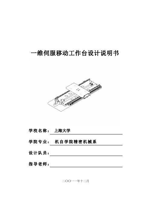
课程设计任务1.设计任务介绍:图1-1 一维伺服移动工作台整体结构为完成一维伺服移动工作台的设计,需设计的机械系统包括:伺服电机、减速器、联轴器、滚珠丝杠副、直线导轨、光栅传感器等。
工作台的承重载荷0300G N =;工作台的轴向载荷060F N =;工作台的最大移动速度max 0.2/V m s =;工作台的有效行程S 600mm =;加减速时间常数0.15t s =;2a 1.33m/s ⇒=加速度3.设计内容简介一维工作台整体结构 电机的选型 滚珠丝杆的选型 支撑单元选择 联轴器选择 转矩探讨 电机的校核 联轴器校核 导轨的选型 轴承的校核 系统精度计算 系统谐振频率计算 光栅的选型课程设计1一维工作台整体结构考虑到工件重量(300N ),工作台轴向载荷(60N )J 均很小,初选不考虑减速器。
Handymig 170i 操作指南说明书

Handymig 170i OPERATOR’S MANUAL IM711 January, 2001Safety Depends on You LiquidArc machines are des igned and built with s afety in mind. However, your overall s afety can be increased by proper installation ... and thoughtful operation on your part.DO NOT INSTALL, OPERATE OR REPAIR THIS EQUIPMENT WITHOUT READ-ING THIS MANUAL AND THE SAFETY PRECAUTIONS CON-TAINED THROUGHOUT.And, most importantly, think before you act and be careful.For use with machine Code Numbers10843A Division of Lincoln Electric Company (Aust) Ply Ltd A.B.N. 36 000 040 308ISO 9001Designed and Manufactured Under aQuality Program Certified byThis manual covers equipment which is no longer in production by The Lincoln Electric Co. Speci cations and availability of optional features may have changed.ii iiSAFETYMar‘95vSAFETY vfor selecting a QUALITY product. We want you to take pride in operating this LiquidArc product ••• as much pride as we have in bringing this product to you!Read this Operators Manual completely before attempting to use this equipment. Save this manual and keep it handy for quick reference. Pay particular attention to the safety instructions we have provided for your protection.The level of seriousness to be applied to each is explained below:TECHNICAL SPECIFICATIONS – Handymig 170iSELECT SUITABLE LOCATIONLocate the welder in a dry location where there is free circulation of clean air into the louvers in the back and out the front of the unit. A location that minimizes the amount of smoke and dirt drawn into the rear louvers reduces the chance of dirt accumulation that can block air passages and cause overheating.STACKINGHandymig 170i ’s cannot be stacked.TILTINGEach machine must be placed on a secure, level sur-face, either directly or on the recommended cart. The machine may topple over if this procedure is not fol-lowed.OUTPUT CONNECTIONSRefer to Figure A.2. 1.Work Cable Access Hole.2.Gun Cable and Control Lead Access Hole.3.Connector Block.4.Gun Trigger Lead Connectors.5.Positive (+) and negative (–) output terminals.FIGURE A.2GENERAL DESCRIPTIONThe Handymig 170i is a complete semiautomatic con-stant voltage DC portable arc welder. Included is a tap-switch controlled, single phase constant voltage transformer/rectifier power source and a wire feeder with welding gun for feeding .023" (0.6 mm) through .030" (0.8 mm) solid steel electrode. Optional kits are available for .035" (0.9 mm) and .045" (1.2 mm) Innershield®NR-211-MP.It is ideally suited for individuals having access to 240 volts 50 Hz AC input power and want the ease of use, quality and dependability of both gas metal arc weld-ing or GMAW (also known as MIG welding) and the Innershield®process (self-shielded flux-cored or FCAW). A convenient chart is mounted inside the wire feed section door for setting welding procedures for 24 gauge (.60 mm) through 5/16" (8.0 mm) mild steel. The machine is rugged and reliable and has designed for dependable service and long life. RECOMMENDED PROCESSESThe Handymig 170i can be used for welding mild steel using the GMAW, single pass, process which requires a supply of shielding gas or it can be used with the self-shielded, Innershield®process (FCAW). OPERATIONAL FEATURES ANDCONTROLSThe Handymig 170i has the following controls as stan-dard: Power ON/OFF Switch, Voltage Control, Wire Speed Control, Trigger Switch, and a Circuit Breaker. DESIGN FEATURES AND ADVANTAGES•“Cold electrode” until gun trigger is pressed for an added measure of safety.*Overload protection — incorporates both a thermo-stat and a circuit breaker.•Quality wire drive with electronic overload protection.•“Quick Release” idle roll pressure arm is easily adjusted.•Reversible, dual groove drive roll, shipped ready to feed .023"/.025" (0.6 mm) diameter wire. The drive roll is easily reversed to feed .030" (0.8 mm) diame-ter solid wire and .035" (0.9 mm) flux-cored diameter wire. Optional drive roll included in .045" (1.2 mm) Innershield®welding kit must be installed to feed .045" (1.2 mm) flux-cored wire.•No external shielding gas is required when used with Liquid Arc steelcore 71T-GS electrode.•Spindle accommodates both 8 in. (200 mm) diameter and 4 in. (100 mm) diameter spools of wire.FIGURE B.1b4+-MACHINE SET UP FOR THESELF-SHIELDED FCAW PROCESS•See PROCESS GUIDELINES in the OPERATION section for selection of welding wire and shielding gas, and for range of metal thicknesses that can be welded.•See the Application Guide on the inside of wire feed section door for information on setting the controls.•Set the “Voltage” and “Wire Speed” controls to the settings suggested on the Application Guide for the welding wire and base metal thickness being used.The voltage control is marked “V” and the wire feed speed is marked ‘’olo.’’•Check that the polarity is correct for the welding wire being used. Set the polarity for DC(–) when welding with Steelcore 71T-GS Innershield elec-trode.See Work Cable Installation in the INSTALLA-TION section for instructions on changing polarity.•When using Innershield electrode, the gasless noz-zle may be used instead of a gas nozzle to improve visibility of the arc.•Connect work clamp to metal to be welded. Work clamp must make good electrical contact to the work piece. The work piece must also be grounded as stated in the “Arc Welding Safety Precautions”at the beginning of this manual.WELDING TECHNIQUES FOR THE SELF-SHIELDED FCAW PROCESSFour simple manipulations are of prime importance when welding. With complete mastery of the four, welding will be easy. They are as follows:•The Correct Welding PositionFigure B.11 illustrates the correct welding position for right handed people. (For left handed people, it is the opposite.)Hold the gun (of the gun and cable assembly) in your right hand and hold the shield with your left hand. (Left handers simply do the opposite.)When using the FCAW Process, weld from left to right (if you are right handed). This enables you to clearly see what you are doing. (Left handers do the opposite.) Tilt the gun toward the direction of travel holding the electrode at an angle as shown in Figure B.18.Refer to Figure B.22.•Learn to strike an arc by positioning the gun over the joint and touching the wire to the work.•Position face shield to protect face and eyes.•Depress gun trigger, hold gun so contact tip to work distance is about 3/8 to 1/2 inch (10 to 12 mm) and the gun is at proper angle.•After you strike the arc, practice the correct electri-cal stickout. Learn to distinguish it by its sound.•When you are sure that you can hold the correct electrical stickout, with a smooth “crackling” arc start moving. Look at the molten puddle constantly, and look at the “ridge” where the metal solidifies.•Run beads on a flat plate. Run them parallel to the top edge (the edge farthest away from you). This gives you practice in running straight welds, and also gives you an easy way to check your progress. The 10th weld will look considerably bet-ter than the first weld. By constantly checking on your mistakes and your progress, welding will soon be a matter of routine.MACHINE SET UP FOR THE GMAW (MIG) Array PROCESS•See PROCESS GUIDELINES in the OPERATION section for selection of welding wire and shielding gas, and for range of metal thicknesses that can be welded.•See the Application Guide on the inside of wire feed section door for information on setting the controls.•Set the “Voltage” and “Wire Speed” controls to the settings suggested on the Application Guide for the welding wire and base metal thickness being used.The voltage control is marked “V” and the wire feed speed is marked ‘’olo.’’•Check that the polarity is correct for the welding wire being used. Set the polarity for DC(+) when welding with the GMAW (MIG) process. See Work Cable Installation in the INSTALLATION section for instructions for changing polarity.•Check that the gas nozzle and proper size liner and contact tip are being used and that the gas supply is turned on. If adjustable, set for 15 to 20 cubic feet per hour (7 to 10 l/min.) under normal conditions, increase to as high as 35 CFH (17 I/min.) under drafty (slightly windy) conditions.•Connect work clamp to metal to be welded. Work clamp must make good electrical contact to the work piece. The work piece must also be grounded as stated in the “Arc Welding Safety Precautions”at the beginning of this manual.WELDING TECHNIQUES FOR THE GMAW (MIG) PROCESSFour simple manipulations are of prime importance when welding. With complete mastery of the four, welding will be easy. They are as follows:•The Correct Welding PositionFigure B.23 illustrates the correct welding position for right handed people. (For left handed people, it is the opposite.)When GMAW (MIG) welding on sheet metal, it is important to use the “forehand” push technique.Hold the gun (of the gun and cable assembly) in your right hand and hold the shield with your lefthand. (Left handers simply do the opposite.)Proper Gun HandlingMost feeding problems are caused by improper han-dling of the gun cable or electrodes.•Do not kink or pull the gun around sharp corners •Keep the gun cable as straight as practical when welding.•Do not allow dolly wheels or trucks to run over the cables.•Keep the cable clean.•Innershield electrode has proper surface lubrica-tion. Use only clean, rust-free electrode.•Replace contact tip when it becomes worn or the end is fused or deformed.D-4 D-4GROUND TEST PROCEDUREThis Troubleshooting Guide is provided to help you locate and repair possible machine malfunctions. Simply follow the three-step procedure listed below.Step 1.LOCATE PROBLEM(SYMPTOM). Look under the column labeled “PROBLEM (SYMPTOMS)”. This column describes pos-sible symptoms that the machine may exhibit. Find the listing that best describes the symptom that the machine is exhibiting. Symptoms are grouped into three main cat-egories: output problems, function prob-lems, welding problems.Step 2.PERFORM EXTERNAL TESTS. The second column labeled “POSSIBLE AREAS OF MISADJUSTMENT(S)” lists the obvious external possibilities that may con-tribute to the machine symptom. Perform these tests/checks in the order listed. In general, these tests can be conducted with-out removing the case wrap-around cover. Step 3.PERFORM COMPONENT TESTS.If you have exhausted all of the recom-mended tests in Step 2, Consult your Local Authorized Field Service Facility.HOW TO USE TROUBLESHOOTING GUIDEIf for any reason you do not understand the test procedures or are unable to perform the tests safely, contact your LOCAL AUTHORIZED LIQUID ARC FIELD SERVICE FACILITY for assistance before you proceed._____________________________________________________________________TROUBLESHOOTING GUIDEObserve Safety Guidelinesdetailed in the beginning of this manual.TROUBLESHOOTING GUIDE Observe Safety Guidelinesdetailed in the beginning of this manual.TROUBLESHOOTING GUIDEObserve Safety Guidelinesdetailed in the beginning of this manual.Handymig 170i WIRING DIAGRAM:Code 10842H a n d y m i g 170i W I R I N G D I A G R A M10/00NOTE: This diagram is for reference only. It may not be accurate for all machines covered by this manual. Thespecific diagram for a particular code is pasted inside the machine on one of the enclosure panels.JapaneseChineseKoreanArabicREAD AND UNDERSTAND THE MANUFACTURER’S INSTRUCTION FOR THIS EQUIPMENT AND THE CONSUMABLES TO BE USED AND FOLLOW YOUR EMPLOYER’S SAFETY PRACTICES.SE RECOMIENDA LEER Y ENTENDER LAS INSTRUCCIONES DEL FABRICANTE PARA EL USO DE ESTE EQUIPO Y LOS CONSUMIBLES QUE VA A UTILIZAR, SIGA LAS MEDIDAS DE SEGURIDAD DE SU SUPERVISOR.LISEZ ET COMPRENEZ LES INSTRUCTIONS DU FABRICANT EN CE QUI REGARDE CET EQUIPMENT ET LES PRODUITS A ETRE EMPLOYES ET SUIVEZ LES PROCEDURES DE SECURITE DE VOTRE EMPLOYEUR.LESEN SIE UND BEFOLGEN SIE DIE BETRIEBSANLEITUNG DER ANLAGE UND DEN ELEKTRODENEINSATZ DES HER-STELLERS. DIE UNFALLVERHÜTUNGSVORSCHRIFTEN DES ARBEITGEBERS SIND EBENFALLS ZU BEACHTEN.JapaneseChineseKoreanArabicLEIA E COMPREENDA AS INSTRUÇÕES DO FABRICANTE PARA ESTE EQUIPAMENTO E AS PARTES DE USO, E SIGA AS PRÁTICAS DE SEGURANÇA DO EMPREGADOR.A Division of Lincoln Electric Company (Aust) Ply Ltd A.B.N. 36 000 040 30835 Bryant Street, Padstow, NSW2211, Australia。
伟迪捷喷码机培训手册

25
14
15
7
18
30
4
5
33 10
23
2
20 21
17 28
32 11 9
16
27 12 19
13
8
32 9 11
30
29
Ink Module Assembly 墨水盒组件
1- 8
TennysonDing
10
Videojet
Excel 培训教材
第二章 系统工作原理
一、墨水喷印过程
前言
墨水喷印过程是基于压力、超声振荡,以及静电干 扰对液体墨线影响的物理现象之上的。
29 Fluids Low Needle Value 液体低位针形阀
25 Make-up Add Solenoid 稀释液添加电磁阀 30 Positive Air 正压空气针形阀
26 Vacuum Check Valve 真空单向阀
1-3
TennysonDing
5
Videojet
Excel 培训教材
EXCEL-100/170I 型结构图之四
电子控制组成部分
37
36
31
34
32
33 35
31 High Voltage Power Supply 双高压电源 35 Low Voltage Power Supply 低压电源
32 K1 Relay K1 继电器
36 Aux. +12 VDC Power Supply 12V 辅助电源
注意:EXCEL 系列喷码机喷嘴驱动的范围是 1-100, 这就允许你进行精密的喷嘴驱动调整。
一个正确的墨滴断点应该与图 3-4 中所示的类 似。在这个例子中应注意到在墨滴断点的尾部附带 形成一个单独的小墨滴叫做卫星点。当调整合适 时,这个卫星点应该在后面的 5 个墨滴内“赶上” 并与母点汇合。注意到断点的形成会据墨水型号而 变化是非常重要的。
浪潮英信NF170服务器使用手册说明书
尊敬的浪潮英信服务器用户本手册介绍了浪潮英信NF170服务器的技术特性与系统的设置有助于您更详细地了解和便捷地使用浪潮英信NF170 服务器以利于污染预防浪潮集团有限公司拥有本手册的版权任何单位和个人不得以任何形式复制本用户手册本手册中的内容如有变动恕不另行通知浪潮集团有限公司 2003 年7 月英信XeonMS-DOSRedhat是RedHat公司的注册商标声 明在您正式使用浪潮英信NF170服务器之前只有您阅读了以下声明并且同意以下条款后如果您对以下条款有任何疑问如您未向我们就以下条款提出疑问并开始使用浪潮英信NF170服务器1在任何时候您不要修改浪潮英信NF170服务器主板BIOS的任何其他参数在您使用的浪潮英信NF170服务器出现任何硬件故障时或您希望对硬件进行任何升级时您不要自行拆卸浪潮英信NF170服务器机箱及机箱内任何硬件设备浪潮英信NF170服务器的CPU内存请您不要将它们和任何其他型号机器的相应设备混用用户在浪潮英信NF170服务器上碰到的任何软件问题由他和我们联系共同解决用户碰到的问题网络管理软件或其他网络产品等的安装我们尤其希望用户能够这样办理请先仔细阅读我们的快速使用指南请联系我们的技术服务中心对于本手册由于产品更新本手册中涉及之各软硬产品的标示"我们"指代浪潮集团有限公司关于本手册第一章开始使用服务器这一章向您详细介绍浪潮英信NF170服务器的技术特性以及如何连接安装第二章 系统硬件这一章向您详细介绍英信NL17O服务器的硬件安装与拆卸情况第四章 安装操作系统这一章向您详细介绍如何在浪潮英信NF170服务器上安装各种主流操作系统我们就用户通常关心的一些问题给出我们的解答以避免您在操作中出现不必要的失误书中出现错误和不足在所难免并及时给我们批评指正目 录第一章 开始使用服务器..................................................11.1 开始使用浪潮英信NF170服务器....................................11.2 NF170服务器技术特性.............................................41.3 浪潮服务器随机资料..............................................5第二章 系统硬件........................................................62.1 上架安装指南....................................................72.2 打开主机上盖....................................................132.3 安装处理器......................................................142.4 安装内存........................................................162.5 安装硬盘........................................................172.6 安装光驱1第一章 开始使用服务器1.1开始使用浪潮英信NF170服务器一配件盒等查看所有包装物请即刻填写一个损坏声明并请按照装箱单清点物品二确保电源接地良好远离热源大风扇电视台发射塔浪潮英信NF170 结构设计为1U机架式请参照下面要求把NF170 服务器放置在合适的机柜里面高度宽度深度前面的空间后面的空间环境温度44.2mm430mm600mm250mm2永不停顿的浪潮英信服务器英信NF170三1前视图图11 硬盘指示灯5 光驱(或挡板)9 Reset按钮4 系统警示灯8 固定门板手拧螺丝3图1-3后视图后视图部件连接NF170服务器1显示器鼠标及电源线等配件备好根据上面介绍的后视图的端口分布鼠标34系统的连接完成1 USB1/2/35 并行接口9 外插PCI卡2 PS/2键盘接口6 显示器接口10永不停顿的浪潮英信服务器英信NF1701.2 NF170服务器技术特性下表总结了NF170服务器的性能MCH 内存总线控制器(北桥)P64H2 64-bit I/O hubDDR-266 ECC register DIMMs ATI Rage. XL 64-bit SVGA 显示控制器SVGA 显示接口可选薄型24X可选薄型1.44MSSI 350W主板集成双网卡Intel. 10/100 自适应快速以太网卡控制器(Intel. 82550PM)1个25针并口2个RJ45网络接口NIC2为千兆3个USB接口技术特性类型处理器芯片组内存系统总线PCI扩展槽IDE通道支持硬盘数目显示卡光驱软驱电源网络I/O接口41.3浪潮服务器随机资料12. 浪潮英信猎鹰管理软件光盘22.快速使用指南3您需要在安装前制作所需的驱动程序软盘从导航软件光盘制作驱动程序软盘到随机配备的空白驱动程序盘片上56永不停顿的浪潮英信服务器英信NF170第二章 系统硬件本章将帮助您完成NF170的上架安装和系统硬件的安装维护开始硬件操作之前 静电释放可能会损坏服务器组件对静电释放进行防护是必要的一定要注意应在ESD工作台上执行本章中描述的操作如果没有这样的工作台用手持拿板卡时,注意只拿板卡的边沿芯片引脚及其它组件要存放在防静电袋中并熟悉使用和调整电子设备所需要的安全惯例和规章要求为避免可能的导致人身伤害或设备损坏网络或调制解调器连线72.1 上架安装指南NF170结构设计为机架式建议您最好把NF170服务器安装到合适的机柜中机柜必须锚定在一个稳固的地方由于重心位置的改变而导致机柜倾倒断开主AC电流这个装置必须很容易发现和使用而不是单个服务器的为了避免电击危险如果服务器电源线插入了作为机柜的一部分的电源插座里如果服务器的电源线插入了在墙上的电源插座里必须为机柜及其内部的其他设备提供适当的接地保护如果您使用的是浪潮专门为该机型所配置的机柜的话请您尽量不要更改机柜内各接地连接如果服务器安装在机柜内不能低于5不能高出35大的温度变动会引起服务器工作不稳定或异常永不停顿的浪潮英信服务器英信NF170通风并且须保证能够每小时排放4100Btu的热量2.1.2 NF170服务器导轨套件清单图2-1所示外轨和中间轨 2根2导轨固定片 4片4固定外轨用螺丝垫圈 8套682.1.3 安装步骤外轨三部分之间相互卡住并可以相对滑动外轨和中间轨是通过导轨固定片固定在机架上的下面说明了如何拆卸导轨12有滚珠的一面朝下左手握住外轨直到能看见内轨和中间轨之间的防滑卡销左手握住中间轨同时拇指按住内轨的防滑卡销右手拇指用力按下内轨的防滑卡销6提起外轨的防滑卡销将中间横杆推回外轨中9永不停顿的浪潮英信服务器英信NF170二. 安装内轨1每个内轨使用两个螺丝2离防滑卡销近的一端靠近服务器尾端3将内轨上第一个螺丝孔位与机箱上第一个孔位对好然后将螺钉拧紧将另一个螺钉插入机箱尾部最后一个孔位5图2-3 安装内轨三. 安装导轨固定片导轨固定片是一个比滑动导轨宽且短的部件主要用来让滑动导轨固定在其上每个导轨固定片是由两颗螺丝来固定的如图2-4所示10按照上述步骤将剩下的三个导轨固定片安装在另外三个竖直轨上四. 安装外轨和中间轨1导轨的平滑面放在导轨固定片的U型槽中先固定导轨后方使外轨的螺丝孔位与后导轨固定片的孔位对准固定外轨在导轨固定片上再固定导轨前方外轨同样使用两个螺丝和螺母把外轨固定在前导轨固定片上同样方法固定另一个导轨1112永不停顿的浪潮英信服务器英信NF170五. 安装服务器到机柜上1. 将中间轨从外轨中全部抽出2. 搬起服务器确信两边的拖架都正确插入后3. 推到不能动时如图2-6所示最终安装好的样子参见图2-7鼠标电缆5图2-6按下中间轨上的防滑卡销图2-7 安装服务器到机柜上2.2 打开主机上盖如图2拧下主机上盖前端的两个螺丝即可卸下主机上盖图21314永不停顿的浪潮英信服务器英信NF170图23安装处理器如果您只安装一个处理器如果安装两个处理器否则会导致系统错误1断开交流电电缆2用手拿处理器的两侧3要把压力杆抬起10 处理器和插槽上都有一个三角形标志的角对齐)注意一定不要用力放置合适后注 意15图 2将散热片安置在CPU上图2- 11安装CPU散热片永不停顿的浪潮英信服务器英信NF1702请使用经过我们测试认证的相应型号产品在安装内存条的时候否则会损坏内存或主板的内存插槽关闭系统电源23注意内存条上的一个缺口和内存插槽上的凸起要吻合直到完全插入内存槽为止和DIMM44即DIMM1和DIMM2,DIMM3Array图2两手分别按住图中内存两端的销子就可以把内存条拆下16172.5 安装硬盘NF170系统提供两个硬盘托架和一个光软驱托架图2拧下固定硬盘托架的螺丝如图2图2永不停顿的浪潮英信服务器英信NF1702使用四颗螺丝安装硬盘到硬盘托架上1515安装硬盘到托架上3并用螺丝固定好16安装硬盘到主机内4182.6安装光驱软驱软驱需要有转接卡才能与主板连接这样可以确保系统的稳定性和可维护性 关闭机箱电源2如图217卸光软驱托架安装软驱3先把转接卡插槽上棕色卡销提起再把卡销卡回1819永不停顿的浪潮英信服务器英信NF170图2-184如图2图2 使用四个螺丝把软驱固定在光软驱托架上20202021安装光驱6如图2图2 把转接卡放置在托架后端8如图2图222永不停顿的浪潮英信服务器英信NF1709如图2图224安装扩展卡231断开交流电电缆打开主机机箱 取下PCI后档片和PCI插槽提升卡 把扩展卡插入提升卡插槽内 把提升卡插入主板插槽内如图25用螺丝钉固定请不要使用5V的扩展卡主板锂电池会维持系统时间和保存系统设置在CMOSRAM中电压降低您就应该更换一个类型相当的电池可能会有电池爆炸的危险换下旧电池后注 意注 意24永不停顿的浪潮英信服务器英信NF170第三章 系统设置前 言BIOS设置是指利用专用的设置程序来调整系统和硬件参数部分硬件的参数和工作方式等BIOS的设置也趋于复杂设置了不当的参数后可能会引起硬件资源的冲突甚至可导致系统不能正常工作建议您使用系统出厂时的默认值在改变服务器BIOS设置前以便在因修改选项而出现系统工作异常时2在未理解各参数表示的意义前3使用过程中较少涉及的选项仅作简单说明或未作说明在显示浪潮英信服务器画面时Press <F2> to enter SETUP此时按下<F2>键在BIOS设置过程中注 意通过+1F1 Help ESC Eixt Select Menu Enter SelectSystem Time此项设置系统的时间可使用和键进行参数设置和项间切换System Date此项设置系统的日期可使用和键进行参数设置和项间切换Legacy Diskette A此项设置软盘驱动器A的类型-/+系统的默认设置为1.44/1.25 MB 3 1/2Primary Master/Primary Slave/Secondary Master/Secondary2526永不停顿的浪潮英信服务器英信NF170Slave此项设置系统的IDE设备按回车键进入下级子菜单-/+TABIDE设备类型的设置有UserATAPI Removableother ATAPI设置完成后2按回车键可以设置主板集成的网络适配器Onboard VGAOnboardUSB关状态通过 键进行参数设置[Enabled]PCI ConfigurationOnboard DeviceServer MenuDMI EventloggingSub-Menu F10 Save&Exit27选择该项进入子菜单按回车键可以设置Onboard NICs和Slot 1--5的相关参数按回车键可以设置系统控制台的相关参数按回车键可以查看CPU的温度系统电压等参数的状态Installed O/S该项用以指定系统所要安装的操作系统使用键进行参数设置Win2000/.NET/XP需要将该项设置为与所安装操作系统相同的选项在该项下面会增加一设置项,需要将该项设置为Enabled.使用键进行参数设置Disabled系统将显示厂商LOGO信息Hyper-Threading该项设置处理器是否运行在Hyper-Threading(超线程)模式下-/+系统的默认设置是可使用默认设置需要将该项设置为Disabled28永不停顿的浪潮英信服务器英信NF1703Set User Password该项用来设置用户密码才能进行设置按回车键按回车键选择该项后按照提示输入密码重新输入一次以确认该项必须在设置了超级用户或用户密码后方可使用可以使用 -/+ 进行设置F1 Help ESC Eixt Select Menu Enter Select294Power Loss Control选择该项后该项设置系统在非正常断电又加电后的状态系统恢复到断电前的状态(开机或关机)如果设置为Disabled直接按开关键将不能关机防止误操作可以使用 -/+ 进行设置Sub-Menu F10 Save&Exit30永不停顿的浪潮英信服务器英信NF1705前面有的项按回车键查看子项选中某一项 -/+进行设置按[ESC]返回主菜单如果连续两次按<ESC>键系统将弹出一个BootMenu菜单F1 Help ESC Eixt Select Menu Enter Select6CPUPeripherals所有选项均不可设置The Exit MenuF1 Help ESC Eixt Select Menu Enter Select按[ESC]键不能退出本菜单然后按回车键退出Exit Saving Changes进行完参数修改后按回车键Save configuration changes and exit now? [Yes] [ No]选择[Yes]31永不停顿的浪潮英信服务器英信NF170选择[No],按回车键将返回到菜单Exit Discarding Changes进行完参数修改后按回车键Configuration has not been saved! Save before exiting? [Yes] [ No]选择[Yes]选择[No], 按回车键将不保存修改的参数并退出BIOS设置程序将返回到菜单选择该项按回车键Load default configuration now? [Yes] [ No]选择[Yes]并返回到菜单并返回到菜单以免造成系统工作异常Discard Changes设置参数后按回车键Load previous configuration now? [Yes] [ No]选择[Yes]取消刚才设置的参数并返回菜单取消恢复原来设置选择该项提示3233选择[Yes]将保存刚才设置的参数选择[No], 按回车键并返回到菜单清除CMOS等跳线设置说明 Pin1Password Clear Pin3BIOS Recovery Pin5CMOS Clear Pin7BIOS Boot Block Write Protect当进行BIOS Boot Block升级时升级完成后 Pin9 Spare Location清除CMOS方法1拆下机箱上盖板参见上图10的跳线帽将Pin5保持10永不停顿的浪潮英信服务器英信NF170秒钟将短接Pin5106恢复断开状态安装好机箱面板34第四章 安装操作系统本章介绍的各操作系统的安装方法都是针对配置IDE硬盘的系统请您参照其相关说明文件随机附件中的两张备用空白软盘用于制作安装操作系统时所需的驱动程序盘可以作为安装参考需要用户根据自己的实际情况而定中文版 浪潮蓝海豚导航软件光盘进入BIOS设置程序具体设置方法可参照本手册第三章的相关内容1Installed O/SWin2000/.NTE/XP项设置为2CD-ROM Drive4.1.2 安装步骤加电启动服务器,将安装光盘插入光驱35永不停顿的浪潮英信服务器英信NF1702Press any key to boot from CD按任意键并开始加载文件系统显示这部分程序准备在计算机上运行Microsoft Windows 2000要开始安装Windows 2000请按R要停止安装Windows 2000并退出安装程序在此我们默认是第一次安装,所以选择按下<Enter>键4Windows 2000许可协议用户可通过按<PAGE Down>浏览协议内容5以下列表显示这台计算机上的现有磁盘分区和尚未划分的空间请按<Enter>要在尚未划分的空间中创建磁盘分区请按D用户可根据实际情况选择在此选中后6请在下面输入大小要回到前一个屏幕而不创建新磁盘分区最小新磁盘分区为 8MBXXX表示磁盘的最大容量36创建磁盘分区大小输入您想创建的磁盘分区大小这里输入的分区应大于774MB7在此选中没有格式化的分区继续安装系统显示安装程序将立即格式化这个磁盘分区然后请按<ENTER>请按ESC系统默认选择用NTFS文件系统格式化磁盘分区建议使用按<Enter>9请梢候系统会显示格式化进度条提示请稍候文件复制完成后重启时选择从硬盘引导37永不停顿的浪潮英信服务器英信NF17010安装向导将在计算机上安装Windows 2000Server以便正确安装Windows 2000Server11如键盘和鼠标等12区域设置如果要更改设置根据需要进行设置在此单击<下一步>自定义软件安装程序将使用您提供的个人信息输入您的姓名以及公司或单位的名称单位然后单击<下一步>输入您的产品密钥继续安装授权模式同时连接数客户端访问许可证S每台计算机必须有自己的设置1638根据实际情况设置计算机名和密码后继续安装安装Windows 2000 组件可以添加和删除Windows 2000 的组件选择组件后18单击<下一步>网络设置安装网络软件允许您连接到其他计算机用户可以根据需要选择然后单击<下一步>工作组或计算机域工作组是具有相同工作组名的一组计算机用户可根据需要选择设置单击<下一步>安装程序开始安装Windows 2000 组件然后继续下一步安装程序完成最后一系列任务注册组件删除用过的临时文件23正在完成Windows 2000安装向导单击<完成>,取出安装光盘24按 <Ctrl+Alt+Del>登录单击 <确定>系统显示如果不需要配置我将在以后配置这个服务器单击<下一步>39永不停顿的浪潮英信服务器英信NF17026启动时显示该屏幕关闭窗口插入蓝海豚导航软件光盘选择Win2k_sp_cn选择Win2k_sp_cn选择根据提示完成安装并重新启动系统选择机型Windows 2000部件型号根据提示完成安装并重新启动系统我的电脑选择系统特性选择设备管理器双击-- 在以太网控制器属性的窗口重新安装驱动程序继续安装单击-- 选择推荐下一步继续安装单击-- 安装程序自动搜索到相应的驱动程序下一步继续安装完成完成驱动程序的安装4041完成Windows 2000 Server的安装过程需要进行如下操作 在操作系统下运行注册表编辑器 查找并选择项 在编辑菜单中点击>EnableBigLba (注意大小写)REG_DWORD0x1退出注册表4.2 安装RedHat Linux8.0本安装过程为RedHat Linux8.0的基本安装步骤具体如何设置有关选项4.2.1安装准备3张 浪潮蓝海豚导航软件光盘进入BIOS设置程序具体设置方法可参照本手册第三章的相关内容1Installed O/SOther项设置为在Boot菜单中将设置为第一引导设备42永不停顿的浪潮英信服务器英信NF1704.2.2安装步骤1. 加电启动服务器2. 在显示boot 按回车键继续Welcome to RedHat Linux4.选择安装操作系统的语言版本本安装过程以选择 为安装语言进行说明keyboard configuration单击<Next>继续安装mouse configuration 2 Buttonmouse7. Install Type选择并根据需要-- Personal desktop-- Workstation-- Server-- Custom本安装过程选择以server为例8.根据需要选择分区方式Manually partitionwith disk druid手动分区单击<Next>继续安装是否继续进行Yes继续分区会显示已有分区的情况用鼠标点击 在Mount point中选中根分区然后选择以同样的方法创建引导分区 用鼠标点击点击在下拉菜单中选中可根据内存的容量来定按照内存容量的2倍进行设置可以把交换分区设置成1GB创建好分区后11.在界面在界面然后单击<Next>继续安装根据实际情况配置网卡的相关参数13. 根据实际需要进行防火墙设置(Firewall configuration)单击<Next>继续安装根据实际需要选择多种支持语言然后单击<Next>继续安装Time Zone Selection选择地区为16.进入界面最少6位单击<Next>继续安装Authentication configuration 单击<Next>继续安装package Group selection根据需要选择要安装的软件包后19. 安装程序进入界面安装程序开始复制文件43永不停顿的浪潮英信服务器英信NF17020.复制文件的过程中第3张安装光盘系统进入界面如果不需要Skip boot diskcreation单击<Next>继续安装请插入一张空白软盘22.安装程序进入界面ATI Rage XL23Monitor configuration根据实际情况选择显示器型号然后单击<Next>继续安装customize Graphics configuration根据需要设置色深和分辨率Please choose your logintype单击<Next>继续安装Congratulations单击系统重新启动进入界面Forward27. 在界面28.系统提示是否进行网上注册点击继续安装Install additional software可根据需要选择是否安装其他应用程序Forward30.系统提示31.登录到系统444.3 .安装FreeBSD5.011. Hit [Enter] to boot immediately, or any other key forcommand prompt.2. Booting [kernel] in 9 seconds... _或者等待10秒钟2Sysinstall是FreeBSD提供的安装应用程序被分成很多菜单和屏幕对于Unix或FreeBSD的新手Standard使用箭头键选择"Standard"3使用FDisk创建slices你的第一个任务是为FreeBSD分配磁盘空间以便Sysinstall能为它做好准备会让你选择安装硬盘根据指导键入<Enter>你会看到硬盘分区的一个列表如果你使用整个硬盘来安装FreeBSD,你就键入A键入S就可以标记slice为可启动分区指出了这个slice是active如果你已给FreeBSD留有空间或不使用全部硬盘空间接着指定你所创建的分区的大小键入<Q>但还没45永不停顿的浪潮英信服务器英信NF170有写入磁盘安装一个启动管理器你现在可以选择安装一个启动管理器你可以选择安装FreeBSD的启动管理器第一种BootMgr 是使用FreeBSD的Boot Manager作为多操作系统启动管理程序第二种选择为standard,即使用标准的主引导区启动系统然后再载入操作系统也不安装任何系统引导程序选择完5FreeBSD分区一般要包括四个分区-一个是交换分区下表说明了分区类型和大小每个其它的文件系统都将被挂在这儿你不需要在这儿存储太多的数据b N/A 2-3倍内存大小 系统的交换空间被保存在这个分区所以46。
戴尔 OptiPlex 170L 用户指南.pdf_1700937327.322075说明书
Dell™ OptiPlex™ 170L 用户指南注、注意和警告缩写词和缩略词有关缩写词和缩略词的完整列表,请参阅词汇表。
如果您购买的是 Dell™ n Series 计算机,则本说明文件中有关 Microsoft ® Windows ® 操作系统的所有参考信息均不适用。
计算机说明文件查找有关计算机的信息 规格 清洁计算机高级功能LegacySelect 技术控制 可管理性 安全保护 密码保护 系统设置程序 引导至 USB 设备 电源按钮 电源管理 超线程小型台式计算机计算机概览正面视图 背面视图 计算机内部组件 系统板组件连接和卸下计算机支架添加和卸下部件开始之前 打开主机盖 电池 插卡 机箱扬声器 驱动器 I/O 面板 内存 电源设备 处理器 系统板 装回主机盖小型塔式计算机计算机概览正面视图 背面视图 计算机内部组件 系统板组件添加和卸下部件开始之前 卸下主机盖 电池 插卡 机箱扬声器 控制面板 驱动器 I/O 面板 内存 电源设备 处理器 系统板 装回主机盖计算机和软件问题高级故障排除 解决问题 获得帮助其它信息Microsoft ® Windows ® XP 特性 词汇表 保修注:注表示可以帮助您更好地使用计算机的重要信息。
注意:注意表示可能会损坏硬件或导致数据丢失,并告诉您如何避免此类问题。
警告:警告表示可能会导致财产损失、人身伤害甚至死亡。
Drivers and Utilities CD (ResourceCD)、操作系统介质和《快速参考指南》都是可选的,并非所有计算机都附带这些物品。
本说明文件中的信息如有更改,恕不另行通知。
©2004 Dell Inc.。
版权所有,翻印必究。
未经 Dell Inc.书面许可,严禁以任何形式进行复制。
本文中使用的商标:D e l l、D E L L徽标、OptiPlex、Inspiron、Dimension、Latitude、Dell Precision、DellNet、TravelLite、PowerVault、PowerApp、A x i m和 Dell OpenManage是 Dell Inc. 的商标;I n t e l、Pentium和 Celeron是 Intel Corporation 的注册商标;Microsoft、M S-D O S和 Windows是 Microsoft Corporation 的注册商标;I B M和 O S/2是 International Business Machines Corporation 的注册商标;NetWare和 Novell是 Novell, Inc. 的注册商标;能源之星是美国环保局的注册商标。
Alarme Ei 170RF 系统说明书
Alarme Ei 170RFn Tube stronboscopique haute intensitén Coussinet vibrant enfichablen Interconnexion sans fil aux appareils RadioLinkn Voyant de transmission RF et voyants d’alimentation n Codage maison uniquenBatterie de secours rechargeable n Avertisseur batterie faiblen Contacts auxiliaires pour connexion de dispositifs supplémentaires n Garantie 5 ansLe modèle Ei170RF est un système d’alarme RadioLink conçu pour avertir les personnes sourdes ou malentendantes dès réception d’un signal d’alarme ou de test. Il comprend un coffret de commande avec unité stronboscopique intégrée et coussinet vibrant enfichable.Le modèle Ei170RF est conçu pour une utilisation permanente sur secteur. Il contient également une batterie rechargeable assurant une alimentation de secours en cas de coupure secteur.Il intègre un tube stronboscopique Xénon à haute intensité avec un objectif spécialement conçu pour produire un flux lumineux à grand angle. Un bouton «test» intégré à l’avant de l’appareil permet de tester facilement le tube stronboscopique, le coussinet vibrant et les bases/détecteurs RadioLink présents dans l’installation.Le coussinet vibrant comprend un connecteur enfichable et est conçu pour être placé sous un oreiller pour réveiller les personnes se trouvant dans l’impossibilité de réagir au signal stronboscopique.Le modèle Ei107RF utilise une technologie de pointe exploitant un émetteur-récepteur et un codage de signal assurant un signal RF robuste et fiable. Il dispose également d’une fonction «code maison» permettant de coder en une seule fois une installation comprenant plusieurs appareils provenant d’installations voisines.Le modèle Ei107RF peut être connecté à des dispositifs optionnels d’entrée et de sortie : récepteurs de radiomessagerie, tubes stronboscopiques, réveils.Alimentation par pile lithium d’une durée de vie de 10 ansF Dès réception d’un signal d’alarme RadioLink ou d’un signal de test, le tube stronboscopique clignote, le coussinet vibrant vibre par cycles de 2 secondes et le voyant Led rouge clignote.Une pression sur le bouton «Test» intégré permet de vérifier et d’activer le tube stronboscopique et le coussinet vibrant. L’appareil envoie également un signal d’alarme RadioLink qui active la totalité des bases/détecteurs RadioLink présents dans l’installation.Les voyants Led indiquent l’état de l’alimentation, les défauts d’alimentation, le statut de l’activité RF et de l’alarme.La sortie auxiliaire 1 est activée dès réception d’un signal d’alarme RadioLink ou d’un signal de test. Cette sortie commande le dispositif relié (optionnel) : coussinet vibrant supplémentaire par sortie auxiliaire 02 est activée dès réception d’un signal d’alarme RaioLink ou d’un signal de test. Cette sortie commande le dispositif relié (optionnel) : récepteur de radiomessagerie par exemple.Dès réception d’un signal émis à partir d’un réveil via l’entrée de l’horloge, le coussinet vibrant s’active. Pour permettre de distinguer ce signal d’un signal d’alarme ou d’un signal de test, la vibration est continue. La lumière stronboscopique n’est pas activée par l’entrée de l’horloge.-Caractéristiques / Modèle Ei170RFTension d’alimentation 230V AC, 50HHz Transformateur fourni avec l’appareilBatterie de secours Au plomb, étanche, rechargeableVoyant d’alimentation Led verte continue lorsque l’appareil est relié au secteur. Voyant ambre toutes les4 sec en l’absence de secteur.Indicateurs d’alarme Tube stroboscopique au xénon (1.5Hz). Voyant Led rouge clignote toutes les sec.En cas d’alarme, le coussinet vibrant fonctionne par cycles de 2sec.Indicateur de panne Voyant Led ambre clignote toutes les 4 sec. en cas de détection de panne ou debatterie faible.Indicateur RF Voyant Led bleu allumé indique la transmission de signaux de radiofréquence.Sortie auxiliaire 1Produit un courant 12V/180mA en cas d’alarme Sortie auxiliaire 2Produit un courant 12V/20mA en cas d’alarmeEntrée de l’horloge 5-24V (AC ou alimentation continue (DC) isolée). Connecteur jack 3,5mm mono Bouton testPermet de tester le tube strnoboscopique, le coussinet vibrant, le panneau ettous les détecteurs de fumée et accessoires RadioLinkGamme de température 4° à 40°CHumidité0% à 90% humidité relativeFréquence Bande de fréquence 868MHz en conformité avec la directive R&TTE 1999/5/EC Interconnexion Jusqu’à 12 détecteurs de fumée/chaleur et accessoires RadioLink peuvent être interconnectés (Ei3100RF , Ei305RF , Ei303RF , Ei405, Ei405TY , Ei168RC, Ei410,Ei411H, Ei428, ei407, Ei174, Ei178)Accessoires Lumière stronboscopique auxiliaire Ei178. Coussinet vibrant auxiliaire Ei174.FixationVis de montage plafond ou applique fourniesMatière plastique Retardateur de flamme UL94VOGarantie5 ans (limitée)HomologationBS 415 : 199. sécurité électrique. Marqué CEEi 170RF。
化验室ISO17025质量手册(ppt 110页)

2.5 质量手册的宣贯、实施
质量手册批准发布后,由质量保证室制定质 量手册宣贯工作计划,并组织实施。
第15章 外部支持服务和供应(暂缺) 15.1 概述 15.2 外部支持服务和供应方的选择 15.3 质量保证措施 15.4 供应与服务的质量承诺 15.5 相关文件
第16章 抱怨(暂缺) 16.1 概述 16.2 抱怨的处理 16.3 质量体系的审核 16.4 相关文件
通用部分描述实例
质量手册
质量体系各要素之间具有一定的相互依赖、 相互配合、相互促进和相互制约的关系,形成了 具有一定活动规律的有机整体。在编写质量体系 文件时必须树立系统的观念,应从检测机构的整 体出发进行设计、编排。对影响检测质量的全部 因素进行有效的控制,接口要严密、相互协调、 构成一个有机的整体。
1.4 质量体系文件的编写原则
2.3 质量手册的管理
质量手册的编制、审批、发布 程序文件、质量文件的编制、审批、发布 监测业务室为质量手册归口管理部门 质量手册的受控管理 质量手册对外发放的管理 对质量手册持有者的要求
2.4 质量手册的编制、修订、再版
中心总技术负责人负责组织编制和修 改质量手册
质量手册中修订的页次应全页更换 关于手册再版的规定 质量手册的再版条件
第3章 3 4.6 4.7 4.8
质量方针和质量目标 质量方针 质量目标 质量承诺 组织和管理 概述 组织机构(包括组织机构框图) 职责与权限 权利委派 保护委托方机密和所有权的规定 指令性检测任务 相关文件 附录
第5章 质量体系、审核和评审 5.1 概述 5.2 质量体系建立 5.3 质量体系文件 5.4 质量体系运行 5.5 内部质量体系审核 5.6 质量体系管理评审 5.7 检测工作偏离程序、标准规范的例外许可规定 5.8 验证和比对实验 5.9 相关文件 5.10 附录
[VIP专享]斑马Zebra 170Xi4全天候工业条码打印机操作手册
![[VIP专享]斑马Zebra 170Xi4全天候工业条码打印机操作手册](https://img.taocdn.com/s3/m/68a4cec784868762cbaed528.png)
斑马Zebra 170Xi4全天候工业条码打印机操作手册Zebra 170Xi41、Zebra 170Xi4条码打印机各部位介绍1.1 打印辊/控制面板/打印头总成/打印头开启杆/色带拾取轴/色带供应轴/介质供应导板/介质供应架1.2 电源指示灯/暂停指示灯/错误指示灯/数据指示灯/液晶显示屏/加号(+)号按钮/上一个按钮/减号(-)按钮/设置退出按钮/下一个保存按钮/校准按钮/暂停按钮/进纸按钮/取消按钮1.3 剥离模式下结构说明打印头开启杆/介质导板/介质导板滚轮/介质供应导板/介质/介质供应架/导板/轴钩/回卷轴/标签背衬/回卷板(已取下)/切纸杆/已打印标签1.4 切纸器模式下结构说明打印头开启杆/介质导板/介质导板滚轮/介质供应导板/介质/切纸器1.5 回卷模式下结构说明打印头开启杆/介质导板/介质导板滚轮/介质供应导板/标签/导板/轴钩/回卷轴/回卷板/已打印标签2、Zebra 170Xi4条码打印机控制面板按钮指示灯说明2.1 控制面板按钮说明■ FEED(进纸),功能:每次按下按钮,可强制打印机送入一张空白标签,①打印机未在打印,立即送入一张空白标签;②正在打印,完成当前标签批次后,送入一张空白标签。
■ PAUSE(暂停),功能:启动或停止打印机操作,或删除错误消息并清除液晶显示屏,①如果打印机空闲,它将立即进入“暂停”模式;②如果打印机正在打印,标签将在打印机暂停之前完成。
■ CANCEL(取消),功能:打印机暂停时,取消打印作业,①打印机未在打印,不打印存储的下一个标签格式;②正在打印,打印完当天标签,并取消下一个标签格式,按下并保持几秒可以取消内存中的所有打印作业。
■ SETUP/EXIT(设置/退出),功能:进入和退出配置模式■ PREVIOUS(上一个),功能:在设定模式下时,可将液晶屏滚动到上一个参数,按下该按钮并保持,可快速滚动。
■加号(+),功能:更改参数值,通常用于增大值,回答“是”,在选项之间滚动,或在输入打印机密码时更改输入值。
伟迪杰 170i 内部培训教材
6. 完成后,显示 “PRINTER IS DRAINED-TURN BLEED VALVED”,这
时空气控制电磁阀会自动关闭,按 “HEAD”恢复空气控制电磁阀,关 排放阀,把墨压调到零。
12mar2003故障情况注释无信号故障signalfaultsignal回收口传感器没有感应到信号墨线没射进回收件墨点没有形成或形成不规则的墨点序列墨线不稳定喷嘴墨水控制阀堵塞墨压电磁阀故障或调压阀失常墨水受污染墨水回收感应线与地线短路折断主控制板损坏喷嘴驱动线断开墨点没有形成电源地线接地不良充电遂道信号线折断10k回收口或回收管道堵塞真空没有形成或不足充电遂道歪斜当加高压时墨线射出回收口回收口的信号线到主板的接头松喷嘴驱动调节不当加油墨请求信号过长故障fluidrequesttoolongfreshinkrequesttoolong加油墨请求开启信号大于30真空低于标准油墨添加过滤器堵塞油墨添加管路部分漏气油墨室内浮子下沉或不正常活动墨水倒流进真空过滤器油墨室中的液位监控开关损坏墨水倒流进真空过滤器真空过滤器堵塞油墨添加阀门污染或不能开启油墨添加阀门膜片磨损油墨添加电磁阀损坏连接电磁阀和油墨添加阀门的铜接头断裂油墨受污染油墨室过满故障reservoiroverfillfault油墨室过满清洗液从回收口不正常进储液器墨水或稀释液添加阀门泄漏墨水或稀释液添加电磁阀损坏油墨室中的液位监控开关中位损坏浮子卡住空气压力故障airpressurefaultwarmupfault空气压力开关断路超过20空气压力低于60psi41bars空气压力监控器损坏空气压力监控器接线松脱或损坏墨水倒流进墨水缓冲器传输部分误动作开机时墨水筒传输请求开关常闭page3127proprietaryinformationivanliuvideojetexcelserial170itrainingmanualrevision
掌上电脑RM-170说明书

智能王MR-170目前的国内PDA市场可以用“群雄逐鹿”来形容,这其中以名人和商务通的争夺最为激烈。
气势恢宏的场面、高深莫测的武功、通天彻地的功能、央视当红小生……这是名人智能王的广告所带给我们的震撼。
本刊评测室现在拿到了名人公司这款最新的掌上电脑——智能王MR-170。
下面我们就来看看这款产品是不是真的那么智能。
外观这款产品给人的第一印象就是“娇小玲珑”(尺寸为96mm×65mm×14mm,重量仅为80g)。
其流线型的超薄机身以及可以更换的涂色外壳(换取涂色外壳38元/个)更使得它成为随身携带PDA的首选。
整个智能王的外观设计与Palm掌上电脑的产品十分类似,在它的屏幕下方呈圆弧形地整齐排列着6个精致的小按钮,从左向右的功能分别为夜光、智能提醒、向上键、向下键、近访电话簿和百家姓。
通过这些按键你可以轻松地实现相应功能,不过遗憾的是这些按键并不能像Palm掌上电脑那样自行设定功能。
在机身左侧面有一个滚轮按键,这就是整个智能王的精华所在,能实现上下和往里三方向的操作,以实现不同的功能,与索尼(SONY)公司独家开发的“Jog Dial”有异曲同工之妙。
机身右侧的手写笔插槽贯穿整个机身,并且手写笔采用两段伸缩式设计,能令手形各异的用户都能操作自如。
“退出”按键位于手写笔插槽下方,简洁而实用。
功能众所周知,丢失用户资料是PDA产品的大忌,因此智能王采用了512KB Flash ROM,确保不会发生因缺电而丢失资料的情况。
在智能王中,我们可以存储约二十几万个汉字,可以进行电话、行程、记事、提醒、联系资料等数据的存储。
而智能王的显示屏为16×16点阵,可以每屏显示100个字(10×10字/行)。
与商务通MBA606相比,智能王显示的字体更加精致小巧,而且非常有质感。
在屏幕的下端从左至右分别有下面的功能触摸按钮:夜光:方便用户在黑暗的环境中使用。
夜光使用的最长时间为8分钟,而且可以自行设定夜光使用时间,而商务通MBA606的夜光时间则是不能自行设定的。
CM-170 声压度计用户手册说明书

USER’S MANUALThis page intentionally left blankContents Introduction (1)Safety Information (2)Overview...................................................................3-4 Before Getting Started.. (5)Getting Started..........................................................6-7 Data Logger & Interval Setup.....................................8-9 Setting The Date & Time.. (9)Calibration Procedure (10)Operating Precautions (10)Measurement (11)Using the PC Software...........................................11-17 Frequently Asked Questions (18)Specifications (19)IntroductionThank you for choosing the CM-170 Sound Pressure Level Meter. You have joined hundreds of thousands of other satisfied Galaxy customers. Since 1977 Galaxy Audio’s professional experience in design and manufacturing ensure our products’ quality, performance and reliability.For the most up to date manual and informationvisit .Safety InformationSafety Information:Read the following safety information carefully before attempting tooperate or service the meter.Use the meter only as specified in this manual; otherwise, the protection provided by the meter may be impaired.Environmental Operating ConditionsAltitude up to 2000 metersRelative humidity 90% max.oAmbient Operating Temperature 0 ~ 40CMaintenance & CleaningRepairs or servicing not covered in this manual should only beperformed by qualified personnel.Periodically wipe the case with a dry cloth. Do not use abrasives orsolvents on this instrument.Safety SymbolsComplies with EMCWhen servicing, use only specified replacement parts.Described below, are the functions of the front panel control buttons and encoders for the CM-170.WindscreenDisplay ScreenPower ButtonMAX/MIN ButtonREC ButtonA/C ButtonFAST/SLOW Button 1234567Range Control Button Microphone AC/DC Signal Output Jack USB Port Tripod Mounting Thread Battery Compartment 8910111213SYMBOL FUNCTIONBattery Capacity IndicatorAuto Power Off IndicatorMaximum/Minimum IndicatorTime Weighting IndicatorLevel Range IndicatorBar GraphTimeFrequency Weighting IndicatorLevel ReadingDateOver-Range Signal IndicatorMemory FullRecording Data Logger IndicatorUnder-Range Signal Indicator Display Screen:Before Getting Started Batteries:Battery Loading:Remove the battery cover on the back and insertfour 1.5V AAA sized batteries. Pay attention to thepolarity as indicated in the compartment.1. Note:It is possible to use size AAA rechargeablebatteries, but a separate external charger must beprovided for such batteries, since the unit is not designed to recharge batteries.Battery Capacity Indicator:When operating the unit on batteries, periodically check this indicator to determine the remaining battery capacity.2.Good Partially Depleted Replace BatteriesExternal Power Supply:A USB Power Supply can be connected to the USB Port.Note:When the AC/DC adapter is connected, the unit will be powered from the adapter, as well as when batteries are inserted (The AC/DC adapter has priority).3.Getting Started Power Button:Press the button to turn the meter on. To turn the unit off, press and hold button down until the screen shows “OFF 3, 2, 1,” then the LCD screen will turn off. MAX/MIN Button:Press the button to enter the maximum and minimum recording mode. Under this mode, the maximum value and minimum value will be stored and automatically updated in the memory.Pressing the button will display the “MAX ” symbol and the maximum value on the display. Pressing the button again will display the “MIN ” symbol indicator and the Minimum value on the display. To exit the maximum and minimum mode, press and hold button down until the “MAX MIN ” symbol disappears.Windscreen:When making outdoor measurements, wind noise at the microphone can cause measurement errors. Such effects can be reduced by using the windscreen.Display Screen.LCD Backlight On/Off:Press to turn on the LCD backlight. This makes it easier to read in dark environments. Press again to turn off the backlight. Themeter can also turn the backlight off automatically after 30 seconds to save battery power.Auto Power Off:To save battery life, by default, when the unit is powered on, it is in auto power mode. The unit will power itself off after 30 minutes if there is no key operation.Auto power off will be disabled under the following circumstances: a. When connecting to a PC.b. When the recording function is in process.Disable Auto Power Off:Press and hold the button and power on the meter. The will not show up on the display, meaning “Auto Power Off” is now disabled. Note: When the user powers on the unit, the LCD will show how much internal memory space is available to use.1. 2. 3. 4.Getting Started Cont. REC Button:When the button is pressed, recording will begin and the “REC”symbol will display. To stop the recording, press the button again. A/C Button:Sets the frequency weighting to A or C. FAST/SLOW Button:Sets the time weighting to Fast or Slow Range Control Button:Each time you press the button, the level range will rotate between “Lo” level, “Med ” level, “Hi ” level and “Auto ” level.Microphone:1/2 inch electret condenser microphone.AC/DC Signal Output Jack:AC: 1 Vrms Corresponding to each range step. (with frequency weighting)Output Signal by standard 3.5mmcoaxial socket signal on pin.Note:At “Auto” level range, output signal is Auto select on “Lo”, “Med”, or “Hi” level range.DC: Output: 10mV/dBUSB Port:Connection to a computer or external power supply input.Tripod Mounting Thread:For long-term measurements, the unit can be mounted on a camera tripod. Proceed carefully, to avoid dropping the unit.Battery Compartment.5. 6. 7. 13. 8. 9. 10. 11. 12.Data Logger & Interval SetupHow to store data in memory.Auto Store IntervalTime Setup:Data Logger & Interval Setup:Press and hold “ ” button and then power on themeter.Press INTV ( ) button, “Int ” appears for interval, as well as a flashing second display.Now set the desired recording interval in minutes and seconds. Press ( ) or ( ) to increaseor decrease the number. Maximum of 1 minute can be set, and the minimum value is limited to“00:01”(=1s). After setting has been performed,press the INTV ( ) button once to get back to thedisplay of the instantaneously measured values. Ifyou want to abort during a setup process, pressbutton to cancel.1. 2. 3. Auto Store:Auto Store Interval Time Setup:Pressing the button will start saving the measured values. The Values are stored in a memory location. Press button again to stop recording.Note: During the recording period, most of the buttons such as the , , and are inoperative. All other settings must be made before starting the recording operation.The LCD will show “FULL ” symbol when 64,000 recording intervals are stored in the memory.Clearing Stored Data:If you want to clear the memory, power off the unit,then press and hold the button and then pressthe button and hold for at least 5 seconds. Thememory.Note:The battery indicator “ ” shows the remainingbattery power. The number of black bars decreases as the battery runs out. When the power is almostempty, “ ” will disappear. Pressing therecording mode, it will stop.Setting The Date & Time:The unit incorporates a clock so that the data loggerfunction can also record the date and time, alongwith the measurement value in the memory.Turn the unit off.1. Enter SETUP mode by pressing and holding thebutton and then press the power button to turn2. Press the CLOCK ( ) button to set the clock.3. Press the ( ) or ( ) buttons to adjust theyear, then press the CLOCK ( ) button to adjustthe next values:(Month > Date > Hour > Minute > Second)4. When finished, press the CLOCK ( ) button toexit the SETUP mode.5. Note:To abort during the process, press the power button to exit the SETUP mode.An internal rechargeable backup battery keeps the clock of the unit running. When the power is turned off, the backup battery isrecharged by the main batteries. The clock will keep running for 30 minutes on the backup battery alone. If the unit is not to be used for an extended period of time, the main batteries should be taken out to prevent possible damage due to battery fluid leakage. Afterreinserting the batteries, be sure to set the date and time again.a. b.Calibration Procedures and Operating Precautions Calibration Procedures:Press and hold the button and then power on1.Insert the microphone housing carefully into the2.insertion cavity of the calibrator.Press the ( ) or ( ) button to increase or3.decrease the number.Press the button to finish. If you want to abort4.during a setup process, press the power buttonto cancel.*Our products are all well calibrated before shipment.It’s recommended to re-calibrate every 1 year.Operating Precautions:Wind blowing across the microphone can greatly1.affect the reading. When using the meter in thepresence of wind, it is advised to use the includedwindscreen.Calibrate the meter before operation if the meter2.has not been in use for a long period of time or ifoperated in a bad environment.Do not store or operate the meter in a high temperature and high 3.humidity environment.Keep the microphone dry and avoid severe vibration.4.Please take the batteries out and keep the meter in a low humidity 5.location when not in use.MeasurementMeasurement:Turn the power on and select the desired response Time and1.Frequency Weighting. If the sound source consists of short bursts or only catching sound peak, set response to FAST. To measureaverage sound level, use the SLOW setting. For general noise sound level, select A-weighting. For measuring sound level of loud sounds with high bass content, select C-weighting.Hold the meter comfortably in your hand, or fix to a tripod, and point 2.the microphone at the suspected noise source. The sound pressure level will then be displayed.When MAX/MIN (maximum, minimum hold) mode is chosen, the3.meter captures and holds the maximum and minimum noise level fora long period, using any of the time weightings.Press and hold the button for 2 seconds to clear the maximum and minimum reading. The “MIN/MAX” symbol will disappear.Using the PC SoftwareCM-170 Setup Using USB Interface Software:The SE323 Software Package Contains:1. Installation CD2. Micro USB CableSystem Requirements:Windows XP / VISTA / 7 / 8 / 10System Requirements:PC or NoteBook with CD-ROM, or download the software online.At least 50 MB hard disk space available to install SE323 Software. Installing the SE323 Software:Insert the setup CD disk into CD disk drive. Windows will run the1.setup.exe automatically.If Windows fails to run the setup.exe automatically, click the start2.button on the Taskbar and select Run. Type E:\SETUP and choose OK. If you can’t find Run, open up “My Computer” from the startmenu and double click the drive from there.Follow the instructions to finish the installation.3.4.It will copy the SE323.exe (executable file) and “help” file to your hard disk (default is :\program files\SE323).For other detailed operation instructions, please refer to the online help while executing the SE323 Software.Main Menu:File:Open - Retrieve files.Save - Save the active window (when the caption bar is highlighted) data to file.Print - Print the graph of the active window.Printer Setup - Select the printer to print from.Exit - Closes the SE232 Program.Real-Time:Run - Start collecting real-time data.Stop - Stop collecting real-time data.Data Logger:Load Data - The user can load recorded data from the meter onto the PC.Erase Memory - The user can erase the memory off theirconnected Sound Pressure Level Meter.View:Control Panel - By opening the Control Panel Window, the user can control the meter via the buttons shown in this window.Real-Time Graph - Opening the Real-Time Graph will display the present data.Graph:Tool Bar:- Display or hide Graph Statistic.- Display or hide Line Cursor Statistic.- Normal Cursor.- When selected, the mouse cursor will become an “ X ” sign when moving to the graph. Click on the graph to mark an “ X ” sign onthe graph.- When selected, the mouse cursor will become an “ I ” sign when moving to the graph. Click on the graph to annotate.- When selected, a window will pop up with a list of annotationsthat can be removed all at once, or one at a time.- Clicking this will clear the graph.Below the slider are the Statistics. It displays start time, sampling rate, data number, and the maximum and minimum of the graph. The statistics also display the maximum, minimum, and average between cursor A and B. These will update automatically when moving CursorA or B.When on the Normal Cursor, you can double click on the graph to open the customization window. You can also click on the “Graph Option” button at the top of the window. In the customization window, you can customize your graph style.You can choose a rectangle area on the graph to zoom in for detail. There are two vertical lines, “Cursor A” (Blue) and “Cursor B” (Red) in the graph. There are time and value displays on the top and right side of each cursor. You can move the mouse cursor over Cursor A or B and click to drag the Cursor left or right. Below Cursor A and B is a slider that you can click and drag to move Cursor A or B.Zoom:You can Zoom in on an area on the graph by using the mouse.To Zoom:Left click and hold.Drag the cursor to select the area you want to zoom in on.Release the mouse button for the zoom to take effect.1. 2. 3.Data Logger:Connect the Sound Level Pressuremeter to the PC. Select “Data Logger”from the main menu drop-down orclick from the tool bar to loadrecorded data from the meter. Therewill be a progress indicator to showthe loading progress.If an error occurs, just click the “Data Logger” again. After the data has loaded, the left-hand side will show how many data sets were loaded and detailed information for each data set (Data set, Date,Time, Rate, Numbers, A/C, Fast/Slow, and Level).Example:1. To Undo Zoom:Click on the “Undo Zoom” button at the top of the window.The first data set will transfer to the graph and tabular on the right-hand side every time after loading recorded data from the Sound Level Meter. You can click on any data set to change the set for the graph.Tutorial - Quick Start to Using the CM-170:Recording Real-Time Data in Waveform:a. Power on the Sound Level Meter first, thenconnect it to a PC USB Port with the cable.b. Start the SE323 Program.c. If the connection is successful, the panel willdisplay the same value as the Sound LevelMeter. If it fails to connect the meter with thePC, it will display “No Connection” on thepanel window in the software.d. When the connection is successful, click to start recording real-time data. There will be a waveform on the Real-Time Graph Window.e. Click to stop recording.1. How to Save the Recorded Real-Time Data to a File:a. Click the graph window you want to save, and the graph window will become active. Then click the File drop-down from the main menu bar and select Save or click from the tool bar. 2. Active Window Inactive Windowb. There will be a save dialog window for you to choose the file name and file type to save. There are three types of file formats you can choose: binary file (*.ghf), text file (*.txt) and EXCEL file (*.csv). The *.ghf file uses the least file space but can only be used in the SE323 software.On the right-hand side, set the waveform graph and statistical information of the data set you chose as you refer to the graph.The text file can be opened by the SE323 software and other word processing programs like word, notepad, etc. The EXCEL formatted file can be opened by the SE323 software and the Microsoft EXCEL program.How to Load the Recorded Data from the Memory of the Sound Level Meter and save it to a file:(Only for the model with Data Logging)a. Power on the Sound Level Meter.b. Press the REC button of the meter to start recording data.c. After a while, press the REC button again to stop recording data.d. Connect the Sound Level Meter to the PC.e. Start the SE323 Program.f. Choose Data Logger from the main menu or click from the tool bar.3. g. In reference to the Data Logger, see Data Logger on page 8.Frequently Asked QuestionsFrequently Asked Questions:How can I save the graph to a file which can be used in EXCEL?1.Answer: When you save a graph to a file, the default file formatis (*.ghf). You need to select the file format (*.csv) in order to save as a useable format for EXCEL.How do I uninstall the SE323 Software?2.Answer: Uninstall the SE323 software by launching the“Add/Remove Programs” applet out of the Control Panel.For some systems you may need to go to:Control Panel > Programs > Uninstall a program.Highlight SE323 and click on “Add/Remove”, or “Uninstall”depending on the PC system. It will then remove the SE323 folder and files from your computer.How do I zoom in on the graph?3.Answer: Click the left mouse button, hold, and drag the cursor toselect the area to be zoomed in on, then release themouse button.When I set up the real-time sampling with a fast rate, some of the 4.sampling data might be lost.Answer: This might be caused by a slow response time of the PC.I get erratic readings outside.5.Answer: Use the windscreen to prevent the wind from interfering with the measurement.Is there an AC adapter for the CM170?6.Answer: The CM170 can be powered via the USB, this will nothowever, charge batteries.My CM-170 keeps shutting off after a while.7.Answer: To save battery life, there is an auto shut off after 30minutes of not touching any buttons this is bypassed when connecting to a PC, or while logging.Specifications:Standard: IEC 61672-1 Class 2, ANSI S1.4 Type 2Microphone: 1/2" Electret Condenser MicrophoneAccuracy: ±1.4 dB (under reference conditions, 94 dB @ 1 kHz) Display: Liquid Crystal DisplayDigital Display: 4 DigitsResolution: 0.1 dBDisplay Update: 0.5 sec.Analog Display: 30 Segment Bar GraphResolution 2 dBDisplay Update: 50 mSMeasuring Level Range: 30 ~ 130 dBLevel Ranges: Lo: 30 - 90 dBMed: 50 - 110 dBHi: 70 - 130 dBAuto: 30 - 130 dBAuxiliary Outputs: AC Signal Output, 1 Vrms at FS (Full Scale) (FS: Means the upper limit of each level range.) DC Output: 10mV / dBFrequency Weighting: A / CTime Weighting: FAST, SLOWDynamic Range: 60 dBFrequency Range: 20 Hz ~ 8 kHzAlarm Function: “OVER” is when input is morethan upper limit of range.“UNDER” is when input is lessthan lower limit of range.Data Logging Capacity: 64,000 RecordsPower Supply: 4 AAA, NEDA 24A, IEC LR03 BatteriesBattery Life: Approximately 24 hrs (alkaline battery)Power Consumption: Approx. 0.2 WExternal Power Supply: 5 VDC (micro USB plug)Operation Temperature: 0C° to 40C° (32F° to 104F°)Operation Humidity: 10 to 90% RHStorage Temperature: 10C° to 60C° (14F° to 140F°)Storage Humidity: 10 to 75% RHDimensions: 10.4" x 2.5" x 1.1" (264 x 63 x 29 mm)(LxWxH)Weight: 0.54 lb (8.642 oz)191-800-369-7768 V20160824© Copyright Galaxy Audio 2016USER’S MANUALSpecifications in this manual are subject to change without notice.For the most up to date manual and informationvisit .WARRANTY Information can be viewed online at /support/warrantyTHREE YEAR LIMITED WARRANTY/support/warrantyPrinted in Taiwan。
CHV170变频器说明书
CHV CHV170170系列矢量变频器系列矢量变频器使用说明书使用说明书版本:版本:V1.0V1.0V1.0深圳市英威腾电气股份有限公司深圳市英威腾电气股份有限公司目 录录1. CHV170硬件 (1)2. CHV170软件 (1)3. CHV170的可选件 (2)4. CHV170的突出性能及应用领域 (2)5. CHV170的核心控制 (3)5.1 CHV170的核心控制模型 (3)5.2 CHV170的实际控制方案 (4)5.2.1 控制开关 (4)5.2.2控制方案组成环节 (5)5.2.3 同步速度给定环节 (6)5.2.4误差形成环节 (8)5.2.5 误差运算环节 (11)5.2.6 CHV170速度组合环节 (15)6. CHV170内部控制功能 (16)6.1 零位变换模块 (16)6.2 UP/DOWN功能模块 (16)6.3 ON/OFF功能模块 (20)6.4 锥度功能模块 (20)6.5 报警功能模块 (23)6.6 刹车功能模块 (26)6.7 模拟量及高速脉冲输出功能 (27)6.8 逻辑输出扩展功能模块 (31)6.9 退火功能模块.................................................................................错误!未定义书签。
6.10 绞线机功能模块...........................................................................错误!未定义书签。
6.11 锥轮拉丝机功能模块....................................................................错误!未定义书签。
6.12内部参数的模拟量设定功能 (31)6.13高速脉冲参数修改功能 (33)7. CHV170控制模型的组态 (34)8. 快捷设置参数功能 (34)9. 参数一览表 (35)10. CHV170应用举例 (35)CHV170系列矢量变频器说明书1. CHV170硬件CHV170的硬件与CHV100完全相同,有关CHV170硬件请比照CHV100硬件说明。
Thermaltake TG ARGB 170 用户手册说明书

Divider 170 TG ARGB Specification
Case Type
Micro Case
Dimension (H*W*D) 426 x 210 x 408.5 mm (16.8 x 8.3 x 16.1 inch)
Side Panel
Tempered Glass x 1
Material Cooling System
SPCC
Front (intake): 120 x 120 x 25 mm ARGB PWM fan (1500 rpm, 27.2 dBA) x 2
Drive Bays Expansion Slots Motherboards I/O Port PSU Fan Support
Radiator Support
PSU max length: 200mm
Remove Components Divider 170 TG ARGB
208mm
178mm
05
06
Divider 170 TG ARGB Power Supply Unit Installation
Motherboard Installation Divider 170 TG ARGB
30
Stand #6-32 x 5 mm
12
Stand #6-32 x 10 mm
2
Stand #6-32 x 28 mm
13
Buzzer
1
PCI Leaf
2
Cable Ties
10
Use For Power Supply / VGA Card Motherboard Stand-off installation
Front Top Rear Front Top Rear
伟迪捷170I喷码机操作说明

墨 水 连 续 喷 射 的 技 术EXCEL-100/170I型结构图之一第二章喷码机系统结构
液路部分(液体容器门关闭时)
13
Fluid Pan Door液体容器门10
12 11
9
9 Ink Pressure Regulator墨水压力调节器 12 Ink Supply Cylinder墨水供给筒(量筒)
10 Vacuum Filter真空过滤器 13 Ink Module Assembly墨水盒总成
11 Final Ink Filter墨水主过滤器
2-1
液路部分(液体容器门打开时)
EXCEL-100/170I型结构图之二
空气动力组成部分
2-2
EXCEL-100/170I型结构图之三
电磁阀组成部分
2-3
EXCEL-100/170I 型结构图之四
电子控制组成部分
31 High Voltage Power Supply 双高压电源 35 Low Voltage Power Supply 低压电源 32 K1 Relay K1继电器 36 Aux. +12 VDC Power Supply 12V 辅助电源33 AC Line Filter 交流电路滤波器 37 Control Board 控制电路板 34 Circuit Breaker 电路中断器
31
323335
34
36
37
2-4
EXCEL-100/170I型结构图之五
喷头组成部分
2-5
EXCEL-100/170I型结构图之六墨水盒、墨水供给筒(量筒)的组成
sembly墨
水盒组件 2-6。
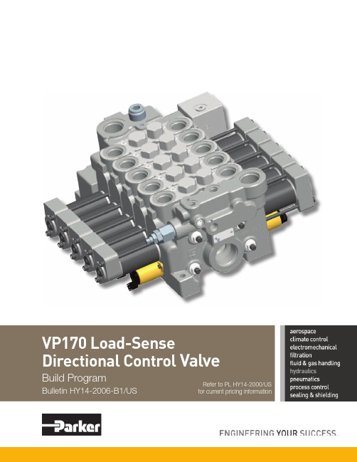
VP170 Load-Sense Directional Control Valve 产品说明说明书
ValveRefer to PL HY14-2000/US for current pricing informationContentsVP170 Build ProgramTechnical InformationGeneral Description (1)Operation (1)Assembly Callout Drawing (2)Benefits ............................................................................................................................................................2 Specifications ...................................................................................................................................................3 Weights .............................................................................................................................................................3 Connections .....................................................................................................................................................3Ordering InformationInlets (4)Clipper Relief Valves (4)Outlets ..............................................................................................................................................................5 Work Sections ..................................................................................................................................................5 Stud Kits .. (6)Spool Positioner Kits (6)Spools ..............................................................................................................................................................7 Port Accessories . (8)Seal Kits (8)Offer of Sale ..........................................................................................................................................................II Safety Guide . (II)FAILURE OR IMPROPER SELECTION OR IMPROPER USE OF THE PRODUCTS DESCRIBED HEREIN OR RELA TED ITEMS CAN CAUSE DEA TH, PERSONAL INJURY AND PROPERTY DAMAGE.• This document and other information from Parker-Hannifin Corporation, its subsidiaries and authorized distributors provide product or system options for further investigation by users having technical expertise.• The user, through its own analysis and testing, is solely responsible for making the final selection of the system and components and assuring that all performance, endurance, maintenance, safety and warning requirements of the application are met. The user must analyze all aspects of the application, follow applicable industry standards, and follow the information concerning the product in the current product catalog and in any other materials provided from Parker or its subsidiaries or authorized distributors.•T o the extent that Parker or its subsidiaries or authorized distributors provide component or system options based upon data or specifications provided by the user, the user is responsible for determining that such data and specifications are suitable and sufficient for all applications and reasonably foreseeable uses of the components or systems.WARNING – USER RESPONSIBILITYThe items described in this document are hereby offered for sale by Parker-Hannifin Corporation, its subsidiaries or its authorized distributors. This offer and its acceptance are governed by the provisions stated in the detailed “Offer of Sale” elsewhere in this document or available at /hydraulicvalve.© Copyright 2012, Parker Hannifin Corporation, All Rights ReservedOFFER OF SALEFor safety information, see Safety Guide SG HY14-1000 at /safety or call 1-800-CParker.SAFETY GUIDEGeneral DescriptionThe VP170 can be configured either as pressure compensated load-sense (PCLS) or as load-sense (LS). Both have the flexibility of sectional construction. The PCLS work section has its own compensator, so that speed control of multiple functions is achieved, regardless of changes in pressure or engine rpms. The key technology integrated into the VP170 is flow-sharing. In pump over-demand conditions, flow-sharing benefits machine productivity by maintaining the speed relationship of the selected functions, but at a reduced speed. Thus, the operator can maintain the rhythm of the machine.The design of the VP170 is modular, allowing for content to be added or taken out of the valve to better match its value to varying machine requirements.For example, it is available as a load-sense pressure compensated, load-sense only, and with and without induced-load protection.The valve can be operated manually, pneumatically, hydraulic remote or with solenoids. The same solenoidis used for on/off and proportional control. A bypass unloader is available for use with fixed-displacement pumps. Also, a new, low-pressure regeneration feature has been designed to overcome the damaging affects of cavitation – premature component wear and spongy operation.The VP170 uses the same spool positioners and port accessories as its open-center counterpart – VA/VG20. The standard spool types are 3-way, 4-way and4-position float. The standard flow limited spools are 8, 16, 24, 32 and 45 GPM based upon a margin pressure of 250 PSI. There is also a standard spool that is not flow limited. OperationThe VP170 (PCLS) is an individually compensated load-sense directional control valve. For optimum horsepower utilization and heat generation, it is nor-mally used with a piston pump. However, it does have the flexibility to be interfaced with a fixed (gear or vane) displacement pump.During single function use, the pump control will deter-mine the flow to the valve, based upon the area open-ing of the spool notch and the load-sense signal being sent back to the pump.During multi-function operation, the pump control will determine the flow for the highest loaded function, while the section compensator will control the flow forthe lighter loaded function.Benefits•Excellent machine controllability – individual pressure compensation in each work section delivers predictable metering with single and multi-function operation,regardless of changes in pressure or input flow. Thisenhances machine control, improves productivity andhelps to make every operator an “expert” operator -- allof which saves money. Also, this valve type lends itself to closed-loop control.•Improved system efficiency – optimized horsepower utilization and heat management are inherent with load-sense pressure compensated valves. This is because ofa closer match between horsepower consumption andhorsepower demand. Fuel savings between 30-50% can be achieved vs. open-center type systems. Also, betterhorsepower utilization may enable the use of a smaller,less costly engine.•Enhanced machine productivity – the VP170 incorporates flow-sharing technology. This means thatduring a pump over-demand condition the valve willautomatically apportion the available pump flow tothe selected functions, based upon control spool areaopenings. The selected functions will maintain their speed relationship, but at a lower overall speed. This automatic adjusting by the valve can improve machine productivity as much as 20% and reduce operator fatigue.•Flexible design – the modular design of the VP170 enables the machine designer to add or remove content to achieve a better “value match” with the machinerequirements. For example, the VP170 is available asload-sense pressure compensated, load-sense only, and with or without induced-load protection. Also, a full line of spool positioners and port accessories is available.•Wide flow range – offers application potential across a family of machines. The VP170 can handle a pump input of 230 LPM (60 GPM) and work sections flows from 30-190 LPM (8-50 GPM).•Induced-load protection – is available for machines whose duty cycles might generate induced loads greater than the load-sense relief valve setting. This is animportant option for valves with flow-sharing technology and has the benefit of maintaining machine productivity.•Addresses cavitation and maintains system responsiveness – a unique, optional low-pressureregeneration feature combats cavitation and the damage it causes to hydraulic components -- reducing warranty costs as much as 15%. This device assures there ishydraulic oil in the loop at all times.•Ease of service – the load-sense check, compensator and transition check are located on top of each worksection making it a “service friendly” design.SpecificationsConnectionsO-ring boss ports SAE-J1926-1BSPP ports ISO 1179-1Pump gage port standardo-ring boss 9/16"-18 UNF , BSPP ports 1/4"-19Thread SizeDescription SAE #O-ring Boss(UNF)BSPP inlet, top 1615/16-121"-11inlet, top 1211/16-123/4"-14inlet, side 1615/16-121"-11inlet, side 1211/16-123/4"-14EH inlet, pilot 69/16-181/4"-19All block ports 69/16-181/4"-19outlet, top 1615/16-121"-11outlet, top 1211/16-123/4"-14outlet, side 1615/16-121"-11outlet, side 1211/16-123/4"-14outlet, side 2015/8-1211/4"-11work section 83/4-16(none)work section 107/8-141/2"-14work section1211/16-123/4"-14Solenoid SpecificationsVoltage 12 or 24 VDC Pilot35 Bar (508 PSI), 15-23 LPM (4-6 GPM)Current Input (I)1.5A for 12 VDC 0.75A for 24 VDC Current (mA) for Spool Shift Start Shift Full Shift 12V 500125024V 250625Insulation Material Class H Duty Cycle 100%R20 Ohm 5.3 (±5%) for 12 VDC 21.2 (±5%) for 24 VDC Fluid Cleanliness 17/14 per ISO 4406Ambient Temperature -30° to 80°C (-22° to 176°F)Fluid Temperature-20° to 80°C (-4° to 176°F)PressuresPump inlets: 350 Bar (5000 PSI)Service Ports: 350 Bar (5000 PSI)Pilot (input or internal supply): 35 Bar (508 PSI)T ank Return: 15 Bar (220 PSI)Solenoid Drain: 2 Bar (29 PSI)Flow RatesMaximum Input: 227 LPM (60 US GPM)Maximum Flow out of Service Ports: 190 LPM (50 US GPM)Max. Return to Service Port: 280 LPM (75 US GPM)LeakagePerformance With mineral oil, 100 SUS @ 120°F at 1100 PSI differentialWorkport w/Steel Plug or no Accessory: 20 cc/min max.Workport w/RV or RV+AC: 24 cc/min max.Thru Reverse Flow Check: 180 cc/min max.Thru Compensator Only (no Reverse Flow Check): 1100 cc/min max.Hydraulic FluidMineral base oil.For other fluids consult factory.Viscosity, working range:15-380mm 2/s (15-380 cSt).Hydraulic Oil TemperatureRecommended Operating Range without Solenoid Operation: -30° to 90°C (-22° to 194°F)Recommended Operating Range with Solenoid Operation:-20° to 80°C (-4° to 176°F)Filtration (ISO 4406)20/18/14 in Main Flow Paths 18/16/13 Pilot SupplyWeightsInlet w/o Bolt-on Block 9.53 kg (21 lb)Inlet with Bolt-on Block 12.25 kg (27 lb)Work Sections ManualHydraulic Remote EH9.10 kg (20 lb)9.53 kg (21 lb)9.98 kg (22 lb)Outlets Standard LP Regen LS Unloader8.62 kg (19 lb)10.43 kg (23 lb)10.43 kg (23 lb)Mounting SurfaceThere is no restriction on orientation.Flatness should be at least 0.5 mm (0.020")Surface must be stable and not put stress on valve.- Top & side ports shipped with plastic closures - Clip RV cavity shipped with a plastic closure - Side gage port SAE 6 with steel plug- Includes section seals- All pilot & drain ports SAE 6 shipped with plastic closures- When ordering on-line, part no's. do not have spacesLS InletLS Inlet with EH BlockAdjustable range is 1500-5100 PSI - LS gage has a steel plugno's. do not have spaces Notes: - All work ports are SAE 12- All work sections have machined port RV cavities with steel plugs - Section seals included- When ordering on-line, part no's. do not have spacesOutlet- Each stud kit contains (4) studs and (8) serrated hex nuts. Stud torque is 500 inch lbs.-When ordering on-line, part no's. do not have spaces- Each stud kit contains (4) studs and (8) serrated hex nuts. Stud torque is 500 inch lbs.- When ordering on-line, part no's. do not have spaces- Spools do not come with a clevis.For cable actuation, 396 1881 015 is needed.-When ordering on-line, part no's. do not have spacesCovering the Industrial and Mobile markets, each catalog is paired with an interactive DVD. Call for your comprehensive guides today. 1-800-C-Parker.Mobile HydraulicsBulletin HY19-1012/US Industrial Hydraulics Bulletin HY01-1001/USMotors Pumps Power Units Valves and ControlsElectronics/RemoteControlsFiltrationCompact HydraulicsCylindersFull line of high and low speed motors provides power up to 15,000 in-lbs of torque.Broad line of energy- efficient hydraulic pumps that includes piston, vane and gear pumps.The most complete line of standard, pre-engineered, cataloged hydraulic power units in the industry.Hydraulic valves for virtually every hydraulic equipment application, from simple to precise control.Parker’s unique IQANapproach combines sturdy, well-tested hardware with intelligent, flexible computing power.Pressure and return line filters enhances machine life, reduces maintenance and lowers costs.Self-contained with a mo-tor, gear pump, reservoir, internal valving, load hold checks and relief valves.Standard and custom hydraulic cylinders for industrial and mobile applications.Industry leader in the design and manufacture of hydraulic rack and pin-ion, and vane style rotary actuators.Piston, bladder and dia-phragm type accumulators, gas bottles and KleenVent reservoir isolators.Parker Chelsea leads the industry for engineering, innovation and performance in auxiliary power systems.Solutions for complex cir-cuits that include threaded cartridge valves integrated into a single manifold./accumulator/oildyne/hydcyl/iqan/hydraulicfilter/hcs/pumpmotor/chelsea/pumpmotor/mobpump/actuator/hydraulicvalveRotary Actuator AccumulatorsPower Take OffExtensive Hydraulic Product OfferingIntegrated HydraulicCircuitsYour Local Authorized Parker DistributorBulletin HY14-2006-B1/US, 3/12Parker Hannifin Corporation Hydraulic Valve Division 520 Ternes Avenue Elyria, Ohio 44035 USA Tel: 440-366-5100Fax: 440-366-5253/hydraulicvalve© 2012 Parker Hannifin CorporationParker Hydraulics International Sales OfficesNorth AmericaHydraulics Group Headquarters6035 Parkland BoulevardCleveland, OH 44124-4141 USA Tel: 216-896-3000 Fax: 216-896-4031Parker Canada Division160 Chisholm DriveMilton, Ontario, L9T 3G9 Canada Tel: 905-693-3000 Fax: 905-876-1958MexicoParker Hannifin de México Industrial Hydraulic Sales Eje Uno Norte No. 100Parque Industrial Toluca 2000 Toluca, Edo. de Mexico CP 50100 Tel: 52 72 2275 4200 Fax: 52 72 2279 9308EuropeHydraulics Group Headquarters La Tuilière 6CH-1163 Etoy, Switzerland Tel: 41 21 821 8500Fax: 41 21 821 8580Latin AmericaParker Hannifin Ind. e Com. Ltda Hydraulics DivisionAv. Frederico Ritter, 110094930-000 Cachoeirinha RS, Brazil Tel: 55 51 3470 9144 Fax: 55 51 3470 9215Parker Hannifin Argentina S.A.I.C.Stephenson 27111667-Tortuguitas-Malvinas Argentinas Pcia. de Buenos Aires, Argentina Tel: 54 3327 44 4129 Fax: 54 3327 44 4199Pan American Division7400 NW 19th Street, Suite A Miami, FL 33126 USA Tel: 305-470-8800 Fax: 305-470-8808Industrial SalesCentral Region 1042 Maple Avenue Unit 331Lisle, IL 60532 USA Tel: 630-964-0796Great Lakes Region6035 Parkland BoulevardCleveland, OH 44124-4141 USA Tel: 216-896-3000Fax: 216-896-4031Gulf Region20002 Standing Cypress Drive Spring, TX 77379 USA Tel: 817-473-4431Fax: 888-227-9454Southwest Region 700 S. 4th AvenueMansfield, TX 76063 USA Tel: 817-473-4431Fax: 888-227-9454Mid Atlantic & Southeast Regions1225 Old Alpharetta Rd Suite 290Alpharetta, GA 30005 USA Tel: 770-619-9767Fax: 770-619-9806Midwest Region 8145 Lewis RoadMinneapolis, MN 55427 USA Tel: 763-513-3535Fax: 763-544-3418Northeast Region P .O. Box 396Pine Brook, NJ 07058 USA Tel: 973-227-2565Fax: 973-227-2467Northwest Region6458 North Basin Avenue Portland, OR 97217 USA Tel: 503-283-1020Fax: 866-611-7308Pacific and Plains Region 8460 Kass DriveBuena Park, CA 90621 USA Tel: 714-228-2509Fax: 714-228-2511Mobile SalesMobile Sales Organization and Global Sales 850 Arthur AvenueElk Grove Village, IL 60007 USA Tel: 847-258-6200Fax: 847-258-6299Asia PacificParker Hannifin Shanghai Ltd.280 Yunqiao Road,Jin Qiao Export Processing Zone Shanghai 201206, China Tel: 86 21 2899 5000 Fax: 86 21 5834 8975Parker Hannifin Hong Kong Ltd.Suites 01-04, 20/F ,Tower 2, The Gateway, Harbour City, Tsimshatsui, Hong KongTel: 852 2428 8008 Fax: 852 2480 4256Parker Hannifin Korea Ltd.18F KAMCO Yangjae Tower949-3 Dogok1-dong, Gangnam-gu Seoul, 135-860, Korea Tel: 82 2 559 0408 Fax: 82 2 556 8187Parker Hannifin India Pvt Ltd.Plot No. EL-26, MIDC, TTC Industrial AreaMahape, Navi Mumbai, 400 709, India Tel: 91 22 6513 7081 Fax: 91 22 2768 6841Parker Hannifin Australia Parker Hannifin Pty Ltd.9 Carrington RoadCastle Hill, NSW 2154, Australia Tel: 612 9634 7777 Fax: 612 9842 5111South AfricaParker Hannifin Africa Pty Ltd 10 Berne Avenue AeroportKempton Park 1620, Republic of South Africa Tel: 19 610 700 Fax: 13 927 213。
- 1、下载文档前请自行甄别文档内容的完整性,平台不提供额外的编辑、内容补充、找答案等附加服务。
- 2、"仅部分预览"的文档,不可在线预览部分如存在完整性等问题,可反馈申请退款(可完整预览的文档不适用该条件!)。
- 3、如文档侵犯您的权益,请联系客服反馈,我们会尽快为您处理(人工客服工作时间:9:00-18:30)。
第三章 键盘说明及菜单1键盘介绍开机 关机SHIFT ALTSPACE SHIFTPRINTREADYENTERSERVICEREADY HELPDELETECANCELControl Keys控制键Arrow Keys 方向键Display Screen显示屏Function Keys 功能键Status Lights 状态指示灯Control keys控制键Numeric Keypad数字键键盘键盘说明:功能键(Function Keys)指F1-F5共五个按键,用于选择菜单或相应的功能。
显示屏(Display Screen):显示菜单、喷印信息、系统故障等信息。
方向键(Arrow Keys):移动光标及调整某些系统参数的数值。
控制键(Control keys):控制系统状态。
其中CANCEL(取消键):用于放弃对当前值的修改。
DELETE(删除键):用于删除光标当前位置的字母或数字。
HELP(帮助键):用来显示系统帮助代码。
ENTER(回车键):用于系统参数修改后确定及退出当前功能项或菜单。
READY/HEAD(准备/喷头):用于打开或关闭喷头。
PRINT(喷印):将喷码机置于喷印或等待状态。
ON(开机):正常起动喷码机。
OFF(关机):执行喷码机关机程序。
状态指示灯(Status Lights):显示当前工作状态及故障指示。
3-12信息编辑3-23喷印设置3-34系统设置3-45维护保养3-5第四章 指示灯及故障分析第一部分:指示灯EXCEL-170I(100)状态指示灯Control Board 电路控制板Column 4第四列Column 3 第三列Column 2第二列Column 1第一列图4-14-1状态指示灯说明:指示灯 状态 说明ACON 交流电源 灯亮表明交流电源接通US12 12V辅助电源 灯亮表明12V辅助电源开启US5 5V辅助电源 灯亮表明5V辅助电源开启HV 高压 灯亮表明高压偏转板上的高压接通+312 +312电源 灯亮表明+312电源开启+5 +5V电源 灯亮表明+5V电源正常开启+12V +12V电源 灯亮表明+12V电源正常开启-12V -12V电源 灯亮表明-12V电源正常开启RSET 复位 灯亮表明机器处于复位状态UPC 3号微处理器 灯亮表明3号微处理器的定时监测型正在进行 COMM 串行通讯状态 灯亮表明机器正在接收来自串行接口的数据 MUIS 稀释液禁止状态 灯亮表明在最近的8个传输周期中有一次或一次以上处于稀释液添加禁止状态TXSW 传送请求开关 灯亮表明此时量筒中墨水液位低,需要添加,喷码机已停止测量墨流时间STSW 开始开关 灯亮表明量筒中的墨水液位处于高位,喷码机重新设置墨流时间为零,此时停止传输OFIL 墨盒溢满开关 灯亮表明墨水盒中出现溢满情况IREQ 墨水请求开关 灯亮墨盒中液位低,此时需从瓶中添加稀释液或墨水 ILOW 瓶液位低检测开关 灯亮表明墨水或稀释液瓶中的液位低,需更换新瓶 MUSW 稀释液请求禁止开关 表明墨盒中液体已满,此时不需添加AIR 空气压力检测开关 灯亮表明输入空气压力大于60磅/平方英寸(4.1巴)PD1 产品检测器状态 灯亮表明此时接收到产品检测信号或没接收到(据设定状况定)EXTS 外部脉冲状态 灯亮表明喷码机正在接收轴编码器的信号EXT1 外部输入1 灯亮表明机器正在接收到用于横向喷头的外部输入信号4-2EXT2 未使用RDY 喷码机准备使用状态 灯亮表明此时喷码机处于等待喷印状态SERV 故障指示状态 灯恒定亮表明喷码机处于警告状态,闪烁表明处于故障状态LEDA 喷头状态 灯亮表明喷码机,高压及墨水接通LEDB 喷印接通状态 灯亮表明喷头正在接收来自缓冲器的喷印数据,键盘上“喷印”灯亮LEDC 未使用ALRT 警告灯状态 灯亮表明喷码机出现故障或警告PH0 相位0 灯亮表明“相位0”是喷码机准备喷印相位PH1 相位1 灯亮表明“相位1”是喷码机准备喷印相位PH2 相位2 灯亮表明“相位2”是喷码机准备喷印相位PH3 相位3 灯亮表明“相位3”是喷码机准备喷印相位 AVAL 空气控制电磁阀 灯亮表明空气控制电磁阀激活打开,压力空气被送到气动组合控制阀TVAL 传输电磁阀 灯亮表明传输电磁阀激活打开,墨水从泵腔传到量筒NVAL 喷嘴电磁阀 灯亮表明喷嘴电磁阀激活打开,压缩空气进入墨压调节器并按一定压力进入量筒,使墨水从喷嘴喷出 IVAL 墨水添加电磁阀 灯亮表明墨水添加电磁阀激活,使墨水从墨水瓶进入墨水盒MVAL 稀释液添加电磁阀 灯亮表明稀释液添加电磁阀激活,使稀释液从稀释液瓶进入墨水盒NDRY 喷嘴驱动状态 灯亮表明有喷嘴驱动输出4-3第二部分:故障分析1.墨水低位警告(FLUID LOW):“墨水低位警告”(FLUID LOW)产生后,应在30分钟内更换新的墨水或稀释液瓶以补充液体。
如果未及时补充,将产生“墨水耗尽故障”(INK OUT FAULT)。
开成时间: 空气控制电磁阀接通60秒后。
条 件: 来自墨水低位开关的信号为“关”(断开状态),且持续时间少于30分钟(一旦信号保持超过30分钟,将发生“墨水耗尽故障”)。
原 因 解 决 方 法1.墨水或稀释液在瓶中的液位低。
检查两个瓶中的液面位置,如果液面位置低,更换相应的新瓶。
2.瓶中传感的空气压力设置不合适。
将瓶过滤器置于瓶中液面以下1英寸(25mm),然后调节液体低位针形阀,使瓶中每秒有2个气泡形成。
3.通往墨水和稀释液中的气管未接好或没有在瓶中正确放置。
检查通入瓶子的气管,确认气管通入瓶中并且瓶过滤器下口低于液面。
4.墨水液位低开关可能损坏。
更换墨水液位低开关。
本表中原因以可能性大小排列2.无相位警告(NOT PHASING):“无相位警告”(NOT PHASING)出现后,可以有5分钟预定时间来进行处理。
否则,将出现“无相位时间”故障(NO PHASE TIME FAULT)。
形成时间:该警告形成于喷码机连续喷印时。
不正常状态:文字信息尾端与下一个产品感应信号之间的时间间隔过小(两者之间至少要有7微秒)。
原 因 解 决 方 法1.产品感应器同时发送两个信号 按下列顺序进行处理,直至不正常状态消失*清洁感应器感应头。
*调节产品感应器灵敏度。
*检查和(或)重新安装产品感应器。
*更换产品感应器。
2.产品在传送带上排列过于紧密 考虑是否有更好的感应方法。
本表中原因以可能性大小排列4-43.无信号警告 (NO SIGNAL):“无信号警告”(NO SIGNAL)与其它两种警告不同之处在于它出现于喷码机准备期间,没有设置预定的时间来用于更正这一状态。
形成时间:该警告形成于喷头准备或重新启动程序中墨水流测试阶段。
不正常状态:是由下列其中之一的不正常状态引起:1)没有墨线。
2)没有断点。
3)墨水滴充电不良。
4)没有检测到回收槽中墨水滴的电荷。
原 因 解 决 方 法1.没有墨水流 按下列顺序进行处理,直到不正常状态消失:*检查喷嘴是否堵塞。
*检查最终墨水过滤器是否堵塞。
(旧机型)*检查墨水供给筒(量筒)出口是否堵塞。
*确认墨水压力是否正常。
2.没有形成墨水滴 按下列顺序进行处理,直到不正常状态消失:* 检查并调节喷嘴驱动。
* 检查测试点5确认喷嘴驱动信号是否正常,否则更换主板。
* 更换喷嘴。
* 检查喷嘴驱动连线连接是否正常。
3.墨水滴充电不良 按下列顺序进行处理,直到不正常状态消失:*检查连接充电通道的10K电阻是否断开。
*检查测试点15输出信号是否正常。
*检查充电通道和控制板之间的屏蔽线是否有断裂或破损。
*更换控制板4. 没有在回收槽检测到墨水滴的带电电荷 按下列顺序进行处理,直到不正常状态消失:*检查回收槽的检测线路连接情况。
*更换回收槽。
*检查至控制板的连线情况,如有必要,更换控制板。
本表中原因以可能性大小排列4-54.实时时钟故障( REAL TIME CLOCK FAULT):形成时间:形成于系统开机后1秒钟。
不正常状态:实时时钟没有发送表明状态信号给控制板它正在工作。
原 因 解 决 方 法1.控制板电池电力不足 更换新电池2.控制板损坏 更换控制板本表中原因以可能性大小排列5.无相位时间故障(NO PHASE TIME FAULT):形成时间:故障形成于喷印过程中。
不正常状态:两次信息喷印时间间隔不够(喷印信息之间至少有7微秒的时间间隔)。
该故障表明“无相位警告”(NOT PHASING)已持续5分钟。
原 因 解 决 方 法1.产品感应器同时发送两个信号 按下列顺序进行处理,直到不正常状态消失:*清洁产品感应器。
*调节感应器灵敏度。
*调节感应器位置。
*更换感应器。
2.产品在传送带上排列太紧密。
考虑是否有更好的感应方法。
本表中原因以可能性大小排列5.空气压力故障(AIR PRESSURE FAULT):形成时间:该故障形成于空气电磁阀接通后5秒钟。
不正常状态:空气压力降至约60磅/平方英寸(4.1巴)以下超过20秒钟。
原 因 解 决 方 法1.喷码机的空气源被切断 检查空气压力源是否与喷码机连接,并且空气压力处于“接通”状态。
2. 喷码机空气源压力降至约60磅/平方英寸(4.1巴)以下 增加输入空气压力,使不少于与喷码机使用的墨水类型相应所需的最小值。
3. 空气压力检测器损坏 按下列顺序进行处理,直到不正常状态消失:*使用电阻表检查空气压力检测开关的工作情况。
正常时关机为打开,开机为闭合。
*更换空气压力检测开关。
4. 空气压力开关和控制板之间的电线断开或松了 按下列顺序进行处理,直到不正常状态消失: *检查线路连接性。
*更换控制板。
表中原因以可能性大小排列 4-6形成时间:有两种形成方式:*当喷码机起动而稀释液或墨水瓶是空的时,主要空气电磁阀打开后立刻就检测出故障。
*“液体低位警告”持续超过30分钟。
不正常状态:墨水低位开关关闭超过30分钟后或启动喷码机时液体瓶是空的。
原 因 解 决 方 法1.墨水或稀释液瓶中液面太低检查瓶中液体余量。
如果液面太低,用满瓶更换。
2.瓶中传感空气压力设置不合适 将瓶过滤器尾端置于瓶中液面下1英寸(25mm)处,然后调节液体低位针形阀,直到达到每秒产生两个气泡。
3.气管与瓶子未连接好或者瓶过滤器在瓶中未安放好 检查瓶过滤器,确认其尾部伸入瓶中并且低于液面。
4.墨水液位低检测开关损坏。
更换墨水液位低检测开关。
表中原因以可能性大小排列7.312伏电源故障(312 VOLT POWER SUPPLY FAULT):形成时间:形成于双高电压电源接通。
不正常状态:控制板检测不到双高压电源输出。
原 因 解 决 方 法1.双高电压电源损坏。
更换双高压电源。
