bufferfly
Q Sepharose Fast Flow 产品说明书
Q1126pis Rev 01/221Product InformationQ Sepharose ® Fast FlowQ1126Product DescriptionQ Sepharose ® Fast Flow is an ion exchangechromatography resin with a quaternary amine (Q) functional group [-CH 2-N +(CH 3)3] attached to Sepharose ® Fast Flow. The Q group serves as astrong anion exchanger, which is completely ionized over a broad pH range. The terms “s trong" and"weak" in ion exchange chromatography refer to the extent of ionization with pH, and not to the binding strength of the functional group to the target species. The parent Sepharose ® Fast Flow is a cross-linked derivative of Sepharose ®. The particle size range is 45-165 µm. The average bead diameter is ~90 µm. The counterion in the product is sulfate (SO 4-2). Recommended cation buffers to use with Q Sepharose ® Fast Flow include alkylamines,ammonium, ethylenediamine, imidazole, pyridine, or Tris. In terms of pH, it is suggested to operate within 0.5 pH unit of the buffer's pK a . With proteins, it is suggested to operate at least 1 pH unit above the pI of the protein, to facilitate binding. Oxidizing agents, and anionic detergents and buffers, should not be used with Q Sepharose ® Fast Flow. Likewise,extended exposure of Q1126 to pH < 4 should be avoided. Several publications 1,2 and dissertations 3-5 cite use of product Q1126 in their research.ReagentQ Sepharose ® Fast Flow is offered as a suspension in 20% ethanol.Approximate Exclusion Limit: average molecular mass of ~4 × 10⁶ DaltonsIonic Capacity: 0.18-0.24 mmol Cl -/mL gel Binding Capacity: ~42 mg BSA per mL gel pH Stability: 2-12Working temperature: 4-40 °CPrecautions and DisclaimerFor R&D use only. Not for drug, household, or other uses. Please consult the Safety Data Sheet for information regarding hazards and safe handling practices. General Resin Preparation Procedure1. Allow the ion exchange medium and ~10 columnvolumes (CV) of buffer to equilibrate to thetemperature chosen for the chromatographic run. 2. Mix the pre-swollen suspension with startingbuffer to form a moderately thick slurry, which consists of ~75% settled gel and 25% liquid. 3. Degas the gel under vacuum at the temperatureof column operation.4. Mount the column vertically on a suitable stand,out of the way of direct sunlight or drafts, which may cause temperature fluctuations.5. Pour a small amount of buffer into the emptycolumn. Allow the buffer to flow through spaces to eliminate air pockets.6. Pour the suspension of ion exchange mediumprepared in Step 3 into the column by allowing it to flow gently down the side of the tube, to avoid bubble formation.7. For consistent flow rates and reproducibleseparations, connect a pump to the column. 8. Fill the remainder of the column to the top withbuffer. Allow ~5 CV of buffer to drain through the bed at a flow rate at least 133% of the flow rate to be used in the procedure. The bed height should have settled to a constant height.9. Using a syringe or similar instrument, apply thesample dissolved in starting buffer to the column. For isocratic separations, the sample volumeshould range from 1-5% of the column volume. If the chromatographic run involves elution with a gradient, the applied sample mass is of much greater importance than the sample volume, and the sample should be applied in a low ionicstrength medium. Ion exchange is used both to concentrate and to fractionate the sample. 10. Elution:• If only unwanted substances in the sample areadsorbed, or if sample components aredifferentially retarded under isocratic conditions, the starting buffer can also be used as the eluent.The life science business of Merck operates as MilliporeSigma in the U.S. and Canada.Merck and Sigma-Aldrich are trademarks of Merck KGaA, Darmstadt, Germany or its affiliates. All other trademarks are the property of their respective owners. Detailed information on trademarks is available via publicly accessible resources.© 2022 Merck KGaA, Darmstadt, Germany and/or its affiliates. All Rights Reserved. Q1126pis Rev 01/22 JJJ,MAM,GCY2•Normally, however, separation and elution are achieved by selectively decreasing the affinity of the molecules for the charged groups on the resin by changing the pH and/or ionic strength of the eluent. This procedure is termed gradient elution. 11. Regeneration: •Either (a) washing the column with a high ionic strength salt solution, such as 1 M NaCl, or (b) changing the pH to the tolerable low and high pH extremes, is usually sufficient to remove reversibly bound material.• When needed, lipids and precipitated proteins canbe removed by washing with 1 CV of 1-2 M NaCl, followed by 1 CV of 0.1 M NaOH in 0.5 M NaCl. • Rinse with several CV of water. Thenre-equilibrate the resin with starting buffer.• If base such as NaOH was used, adjust the pH ofthe resin to neutral before storing or using.12. Storage: Q Sepharose ® Fast Flow may be storedat 2-8 °C in water with 20% ethanol added as an antibacterial agent.General NotesCation versus Anion Exchanger• If sample components are most stable below their pI values, a cation exchanger should be used. • If sample components are most stable above their pI values, an anion exchanger should be used. •If stability is good over a wide pH range on both sides of the pI, either or both types of ion exchanger may be used.Strong versus Weak Ion Exchanger•Most proteins have pI values within the range 5.5-7.5, and can thus be separated on both strong and weak ion exchangers.•When maximum resolution occurs at an extreme pH and the molecules of interest are stable at that pH, a strong ion exchanger should be used. Choice of Buffer, pH, and Ionic Strength• The highest ionic strength which permits binding should normally be used.•The required buffer concentration varies fromsubstance to substance. Usually, an ionic strength of at least 10 mM is required to ensure adequate buffering capacity.•As salts (such as buffers) help to stabilize proteins in solution, their concentration should be highenough to prevent denaturation and precipitation.References1. López, G. et al ., Eukaryot. Cell , 14(6), 564-577(2015).2. Bhargava, V. et al ., Dev. Cell., 52(1), 38-52.e10(2020).3. Fu , Yinan, “Structure and dynamics ofPseudomonas aeruginosa ICP”. University ofGlasgow, Ph.D. dissertation, p. 126 (April 2009). 4. Redmond, Miranda , “The Role of N-TerminalAcidic Inserts on the Dynamics of the Tau Protein ”. University of Vermont, Ph.D. dissertation, p. 22 (May 2017).5. Taylor-Whiteley, Teresa Rachel , “RecapitulatingParkinson’s disease pathology in athree-dimensional neural cell culture mode ”. Sheffield Hallam University, Ph.D. dissertation, p. 58 (September 2019).NoticeWe provide information and advice to our customers on application technologies and regulatory matters to the best of our knowledge and ability, but without obligation or liability. Existing laws and regulations are to be observed in all cases by our customers. This also applies in respect to any rights of third parties. Our information and advice do not relieve ourcustomers of their own responsibility for checking the suitability of our products for the envisaged purpose. The information in this document is subject to change without notice and should not be construed as acommitment by the manufacturing or selling entity, or an affiliate. We assume no responsibility for any errors that may appear in this document.Technical AssistanceVisit the tech service page at /techservice .Standard WarrantyThe applicable warranty for the products listed in this publication may be found at /terms .Contact InformationFor the location of the office nearest you, go to /offices .。
华为 P40 手机用户指南说明书

Mobile USBSpinpoint M8U250GB 320GB 500GB 640GB 750GB 1TBModel HN-M250ABB HN-M320ABB HN-M500ABB HN-M640ABBHN-M750ABBHN-M101ABB Samsung Models FEATURES• Max. 500GB formatted capacity per disk • SilentSeek™ • TuMR/PMR head with FOD technology • NoiseGuard™• USB 3.0 Interface Support• Load/Unload Head Technology Capacity 1 250 ~ 750GB, 1TBTemperature InterfaceUSB 3.0 Operating 5 ~ 55 °C Buffer DRAM Size 28 MBNon-operating -40 ~ 70°C Rotational Speed5,400 RPM ClassHumidity (non-condensing) Operating 5-90 % Non-operating 5-95 %Average Seek time (typical)12 ms Linear Shock (1/2 sine pulse)Average Latency 5.6 ms Operating, 2ms 325 G Data Transfer RateNon-operating, 2ms 750 G Media to/from Bu er (Max.)145 MB/s Vibration (swept sine, 1/4 octave per minute) Bu er to/from Host (Max.)400 MB/sOperating 0.9 Grms Drive Ready Time (typical)34 secAltitude (relative to sea level) Operating -300 to 3000 m Non-operating -400 to 15000 mNon-recoverable Read Error 1 sector in 1014bitsControlled Ramp Load/Unload 600,000Height 9.5 mm Idle2.4 Bel Width 69.85 mm Performance Seek 2.6 BelLength104 mm Weight (max.)107 gVoltage+5V±5%* Note : Design and speci cations are subject to change without prior notice.Spin-up Current (Max.) 750 mA 1 1MB = 1,000,000 Bytes, 1GB = 1,000,000,000 BytesSeek (AVG)43.0 W Accessible capacity may vary as some OS uses binary numbering system Read/Write (AVG)3.2 W for reported capacityLow Power Idle (AVG) 1.8 W 2 A small portion of the 8MB bu er memory is reserved for rmware use Standby (AVG) 1.4 W 3 Power-On to Drive Ready Sleep (AVG)1.4 W4 30% duty cycle, random seek2.5" HDD product speci cation Rev2.1Match with product manual Rev2POWER REQUIREMENTS ACOUSTICS Capacity DRIVE CONFIGURATION ENVIRONMENTAL SPECIFICATIONS PERFORMANCE SPECIFICATIONS RELIABILITY SPECIFICATIONS PHYSICAL DIMENSIONModel8 MB8 MB ST 250LM003ST320LM005ST500LM014ST640LM019 ST750LM023ST1000LM025 Seagate Models。
JUNO-Di 专业合成器商品说明书

Over 1,000 Great Sounds!
Let’s Go!
The JUNO-Di was born to travel. It’s strong yet amazingly light weight (only 11 lbs. 8oz.) making it easy to lift and carry. The battery compatibility lets you play for up to five hours without plugging in (uses Ni-MH AA-size rechargeable batteries). When used in conjunction with a battery-powered amp, such as Roland’s famous CUBE Street® or MOBILE CUBE, the JUNO-Di can be played and heard anywhere. A batterylife indicator on the front panel ensures that you won’t lose power unexpectedly.
• Professional synthesizer with over 1,000 sounds onboard • Friendly, intuitive user interface • Battery operation for mobile use (supports Ni-MH AA-size rechargeable batteries) • MP3, .WAV, AIFF and SMF playback capability via optional USB memory — perfect for backing
SequenceManager Logix Controller-based Batch和排队解决方
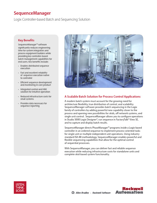
SequenceManagerLogix Controller-based Batch and Sequencing SolutionA Scalable Batch Solution for Process Control ApplicationsA modern batch system must account for the growing need for architecture flexibility, true distribution of control, and scalability. SequenceManager software provides batch sequencing in the Logix family of controllers by adding powerful new capability closer to the process and opening new possibilities for skids, off network systems, and single unit control. SequenceManager allows you to configure operations in Studio 5000 Logix Designer®, run sequence in FactoryTalk® View SE, and to capture and display batch results.SequenceManager directs PhaseManager™ programs inside a Logix-based controller in an ordered sequence to implement process-oriented tasks for single unit or multiple independent unit operations. Using industry standard ISA-88 methodology, SequenceManager enables powerful and flexible sequencing capabilities that allow for the optimal control of sequential processes.With SequenceManager, you can deliver fast and reliable sequence execution while reducing infrastructure costs for standalone units and complete skid-based system functionality.Key BenefitsSequenceManager™ software significantly reduces engineering time for system integrators and process equipment builders while providing key controller-based batch management capabilities for end users. Key benefits include:• Enables distributed sequence execution • Fast and excellent reliability of sequence execution native to controller • Efficient sequence development and monitoring in core product • Integrated control and HMI solution for intuitive operation • Reduced infrastructure costs for small systems • Provides data necessary for sequence reportingDistributed Batch Management Based on Proven TechnologyBuilt Upon Rockwell AutomationIntegrated ArchitectureSequenceManager was built using the standard control and visualization capabilities found in Rockwell Automation® Integrated Architecture® software. SequenceManager is a new capability that is builtinto Logix firmware that uses visualization through FactoryTalk® View SE to create an integrated sequencing solution. Combined with event and reporting tools, SequenceManager software is a complete batch solution for single unit and skid-based process applications.Scalable Controller-based Solution SequenceManager allows flexible design for skid-based equipment to be developed, tested and delivered asa fully functioning standalone solution but, if needed, seamlessly integrated into a larger control system. This strategy provides the end user with the option to integrate equipment without imposing design constraints on the OEM delivering the skid. Additionally, it enables the end user to deliver equipment as a standalone system without the constraint to scale to a larger process solution in the future. This batch solution offers scalability to help prevent costly redesign and engineering.Flexibility to Meet Process Needs SequenceManager enables you to expand your process control on skid based equipment that performs repetitive tasks and decision-making abilities. By using the ISA-88 methodology, SequenceManager allows for control design that can be adopted to fit the needs of the process industries without the constraints of custom application code. Built-in state model handling provides for fast and easy configuration while maintainingcontrol of the process.Editor and ViewerAs a brand new program type in Studio 5000 Logix Designer®, SequenceManager™ software gives the user the power and flexibility necessary to create dynamic recipes to maximize the effectiveness of the process control system.Without limitations on steps and parameters, and the ability to run parallel phases, to branch, and to loop back and rerun steps, SequenceManager removes the barriers in achieving effective batch within the controller.Sequence ExecutionProcedural sequences are executed through nativefunctions in the controller. With an integrated ISA-88 state model, the control and states of phases can be assured. Standard batch functionality, such as manual control and active step changes, are included to give the operational flexibility that is needed to respond toabnormal process conditions.Allowing for an Intuitive Batch ApplicationResponsive batch interactions between the controller and equipment, along with intuitive operator interfaces, provide the core of a truly distributed batching strategy that drives ISA-88 procedural models.Allen-Bradley, FactoryTalk Batch, FactoryTalk® View SE, Integrated Architecture, Listen.Think.Solve., PhaseManager, PlantPAx, Rockwell Automation, Rockwell Software, SequenceManager, and Studio 5000 Logix Designer are trademarks of Rockwell Automation, Inc. Trademarks not belonging to Rockwell Automation are property of their respective companies.Operator ViewerFactoryTalk® View SE and ActiveX controls monitor and interact with a running procedural sequence through the HMI. Advance ActiveX controls provide an intuitive interface for controlling sequences and changingparameters from the operational environment. Improved capabilities allow the user to perform manual step changes and acquire control easily.Reporting and AnalyticsSequenceManager data generates events that are used to produce batch reports and procedural analysis. A separate event client transfers the event data from the Logixcontroller to a historical database. SequenceManager uses the same data structure and reports as FactoryTalk Batch, which provides a consistent and intuitive batch reporting tool among Rockwell Automation® Batch Solutions.Additional InformationVisit us at /processPublication PROCES-PP001A-EN-E – June 2016Copyright © 2016 Rockwell Automation, Inc. All Rights Reserved. Printed in USA.。
SIMD计算机的互连网络

一次混洗
000 0
0 000
001 1
1 001
010 2
2 010
011 3
3 011
… PION ……
LM P1 …… IPCN
网络
互连网络的特性
互连网络通常是用有向边或无向边连接有限个结点的 组成
互连网络的主要特性有: 网络规模:网络中结点的个数 结点度:与结点相连接的边数称为结点度。包括入度
和出度。进入结点的边数叫入度,从结点出来的边数 那么叫出度 距离:两个结点之间相连的最少边数 网络直径:网络中任意两个结点间距离的最大值。用 结点间的连接边数表示 结点间的线长:两个结点间连线的长度。用米、公里 等表示 对称性:从任何结点看到拓扑构造都是一样的网络称
循环互连网络:通过屡次重复使用同一个单级互连网 络以实现任意结点到结点之间的互连。
多级互连网络:将多套一样的单级互连网络连接起来, 实现任意结点到结点之间的互连。
全排列互连网络:不仅能够实现任意结点到结点之间 的互连,而且能够同时实现任意结点到结点之间的互 连
全穿插开关网络:除了能够同时实现任意结点到结点 之间的互连之外,还能够实现播送和多播。
和。 发送方开销(Sender overhead):处理器把消息放到互连网
络的时间。 接收方开销(Receiver overhead):处理器把消息从网络取
出来的时间。 一个消息的总时延可以用下面公式表示:
总时延=发送方开销+飞行时间+消息长度/频宽+接收方开销
Speedybee F405 WING FC Board User Manual

Specification overviewSpeedybeeF405 WING APPPart1 -OverViewSpeedybee APP Installation guide FacebookAssembly InstructionsM2x4 smallhead cross screwThe direction ofthe arrow is themachine headWireless BoardFC BoardPDB BoardM3x8.1 mmSilicone GrommetsM2 x 12 copperStandoff SpacerM3x4 mmSilicone GrommetsABC1.Align the pin headers between boards andthen press the two boards together tightly.2.Install both boards and onto board ,and tighten the screws.A BA B CAssembly orderABCCFC Board FrontPart2-hardware descriptionLayoutDigital airspeedsensor connectorAnalog VTX solder padsThe default power supply is 9V. Ifthe VTX can only be powered by5V, please change the PDB board'sVTX BEC to output 5V.Telemetry modulesolder padsTelemetry moduleconnectorRS SI sol de r p ad sSBUS inputpin headersMotor and servo outputpin headers MicroSD cardslotDigital VTXsolder padsAnalog camera solder padsAnalog airspeedsensor connectorELRS receiver pin headers same asthe Telemetrymodule connectorAnalog RSSI signalinput, supportsup to 3.3VWith inversioncircuit, connectedto RX2PWM1-11The default power supply is 9V. Ifthe camera can only be poweredby 5V, please connect the powersupply to the 5V solder pad.Built-in voltage divider circuit,supports up to 6.6V.Use these pin headers to connectthe ELRS/TBS receiver.GPS moduleFC Board BackSH1.0 6PAnalog cameraconnectorGPS module connectorAirspeed sensorsolder padsUSB extenderconnectorDigital VTXconnectorConnect to the PDBboardUART6 solderpadsVTXT G9VNCCAMGND9VSBUSGNDRX5TX5G9SDASCL4V5G T RSH1.0 4PThe signals are thesame as theairspeed sensorconnector.Analog VTX connectorUSB extender frontBuzzer USB TYPE-C PortBuzzer mute switchoperating state, the BOOTbutton is also used forcontrolling otherfunctions of thewireless board.FC RGB statusindicator BOOT buttonFC board connectorPDB board FrontConnect as shownin the diagramNote: TX800 requires5V power supply.VTX BEC voltageselection jumperServo BEC voltageselection jumper 12V outputDefault 9V output5V output6V outputDefault 5V output7.2V outputDO NOT connect ESC BEC outputto Vx pad (Red wire in middle ofconnector).4-level battery level indicator.Note: disconnect the UART6 jumper onthe back of the wireless board to useTX6 RX6. TX1 RX1 shares the same signalas the ELRS/TBS receiver pin header.Wireless status indicator (RGB LED)LED mode indicator(orange LED):, and Wireless board FrontLED mode indicator(orange LED)Battery LED:BLE not connectedGreen solid:BLE connected successfullyWhite slow flashing :Wi-Fi not connectedWhite Solid:Wi-Fi connected successfullyBlue slow flashing:Classic Bluetooth SPP not connectedBlue Solid:Classic Bluetooth SPP not connectedRGB LED off: Wireless module turned offPressing the BOOT button for 6 seconds can switch between the 4wireless modes. When the yellow LED flashes rapidly and the boardautomatically restarts, the switch is successful.Orange light always on:Solid orange LED means the 4 sets of LEDstrips are in SB_LED mode, controlled by the wireless chip.A short press of the BOOT button cycles through different displayeffects when the FC is operating normally.Orange light is off - Off orange LED indicates FC_LED mode, wherethe FC controls the 4 sets of LED strips directly.Press and hold the BOOT button for 3 seconds to switch betweenFC_LED mode and SB_LED mode.The maximum power supply for theLED connector is about 5.2V 1.3A.When the power exceeds the limit,the resettable fuse will cut off thepower supply. Please reduce thenumber of light beads appropriatelywhen the power exceeds the limit.Taking SpeedyBee Programable2812 Arm LED strips as an example,a total of 17 LED strips can beinstalled, including approximately68 light beads.LED strip connectorUART6 jumperSH1.0 3PSH1.0 3PSH1.0 3PWiring DiagramUSB extenderSR ST4S2S1VX VX4V5G G GGGGGGGVXVXVXVXVXVXS3S4S5S6S7S8SR14V5GND5VT4R4G8I428P7AA12203T E L EM2/4Wireless boardFC boardPDB boardPower supplyThe power distribution logic for the F405 WING APP is as follows:1、 The 9V pad uses a VTX&CAM BEC for power supply. When the VTX&CAM BEC switches to another voltage through the pad jumper, the 9V pad will output the corresponding voltage.2、The Vx pin headers use a Servo BEC for power supply. When the Servo BEC switches to anothervoltage through the pad jumper, the Vx pin headers will output the corresponding voltage.3、The default voltage for the FC BEC is 5.2V, with power output divided into three directions:·The first path directly outputs to the 5V pad.·The second path outputs to the onboard chip and 4V5 pad through a diode.·The third path outputs to the LED connector through a self-recovering fuse and reverse connection protection circuit.The limit for the LED connector power supply is approximately 68 pieces of SpeedyBee 5050 LED strip beads. Do not exceed this limit.To test if other brands of LED strips meet the power requirements, you can take the following steps:·After connecting the LED strip, let the flight controller be powered and idle for 10 minutes. Observe if the color of the LED strip suddenly dims and feel the wireless board with your hand. If it feels very hot, the power supply is insufficient, and you need to reduce the number of LED beads.·You can also use a multimeter to test the voltage of the 5V pad or the LED strip power pad. If thevoltage is below 5V, it indicates that the power supply is insufficient, and you need to reduce thenumber of LED beads.Note: If your ESC supports BEC output, do not connect the ESC BEC red wire to the Vx pinheaders, as this may burn the ESC or Servo BEC.Please note that the FC BEC can provide a continuous current of 2.4-2.5A and a peak current of 3A. The onboard chip requires less than 1A of power, GPS and receivers generally require less than 0.1A, and the wireless controller requires 0.1A.If the LED connector uses a maximum of 1.3A, the 5V pad will have no remaining capacity.If the LED connector is not used, the 5V pad will have a 1.3A surplus.APP connectionPart3-Firmware upgrade andAPP connection①Press and hold the BOOT button , andconnect the FC to the computer viaUSB cable.②Open the INAV Configurator on yourcomputer, go to the "Firmware Flasher "page, select the flight controller targetas "SPEEDYBEEF405WING", and thenflash the firmware.③To flash Ardupilot firmware, follow thesame steps as above, select "LoadFirmware [local]", and then flashthe firmware.SpeedyBee F405 WING APP not supportingwireless firmware flashing, please update thefirmware on a computer. Follow these steps:Check the color of the wireless status indicator. If it's not flashingwhite, press the BOOT button for 6 seconds to switch to white.Then connect to the "Speedybee F405Wing" Wi-Fi and openQGroundControl, it will automatically connect.Firmware upgradeConnecting Ardupilot firmware to QGroundControl app.Check the color of the wireless statusindicator .If it's slow flashing green, open theSpeedyBee app and follow thesteps to connect to thecorresponding product.Connecting INAV Firmware toSpeedybee APP.23APP ConnectionSuitable for different flight control firmware and Configurator. The supported apps are listed in thefollowing table. It is recommended to use Bluetooth BLE mode for iNav and WiFi mode for Ardupilot.Part4-SpecificationsSpeedyBee F405 WING FC board STM32F405,168MHz,1MB FlashICM-42688-P SPL006-001AT7456EMicroSD Card Slot6 sets(USART1, USART2, USART3, UART4, UART5, UART6(Dedicated for Wireless board Telemetry connection))1x Used for magnetometer, digital airspeed sensor 4x (VBAT, Current, RSSI, Analog AirSpeed)12x (11+1“LED”pad)Supported,connected to UART1Built in inverter for SBUS input (UART2-RX)3x LEDs for FC STATUS (Blue, Green) and 3.3V indicator(Red) 1x RGB Supported,Named as RS .INAV:SpeedyBeeF405WING(default)ArduPilot: SpeedyBeeF405WINGMCUIMU(Gyro&Accelerometer) Barometer OSD Chip Blackbox UART I2C ADC PWMELRS/CRSF receiver SBUS LED RSSISupported FC FirmwareSpeedyBee F405 WING PDB boardInput voltage range Battery Voltage Sensor Battery Current Sensor TVS Protective diode FC BEC outputVTX BEC output OutputServo BEC output 7~36V (2~6S LiPo)Connect to FC board VBAT, 1K:10K (Scale 1100 in iNav, BATT_VOL T_MUL T 11.0 in ArduPilot)90A continuous, 215A peak Connect to FC board Current (Scale 195 in iNav, 50 A/V in ArduPilot)YesOutput 5.2V +/- 0.1V DC Continuous current 2.4 Amps, 3A Peak Designed for FC, Receiver, GPS module, AirSpeed module, Telemetry module, WS2812 LED_StripOutput 9V +/- 0.1V DC Continuous current 1.8 Amps, 2.3A Peak Voltage adjustable, 9V Default, 12V or 5V via jumper Designed for Analog Video Transmitter,Digital Video Transmitter, Camera.Output 4.9V +/- 0.1V DC Continuous current 4.5 Amps, 5.5A PeakVoltage adjustable, 4.9V Default, 6V or 7.2V via jumper Designedfor Servos.BLE mode, connect to Speedybee APPClassic Bluetooth SPP mode, connect to QGroundControl APP , MissionPlanner4x WS2812 LED strip connectors, adjustable colors and flashing modesMax 5.2V 1.3A, supports around 68pcs 5050 WS2812 LED beads4x RGB indicator LED for battery level display by number of lightsWireless Configuration(long press BOOT button for 6 seconds to switch modes)LED strip controller (short press BOOT button to switch effects, long press 3 seconds to switch modes)On-board battery level indicator Wi-Fi mode, connect to QGroundControl APP , Speedybee APP , MissionPlanner, etc.SpeedyBee F405 WING Wireless boardPart5-pin mappingUART USB TX1 RX15V tolerant I/OUART1ELRS/TBS receiverSBUS receiver, SBUS pad = RX2 with inverter SmartPort Telemetry,enable Softserial_Tx2GPS USER DJI OSD/VTXOnboard wireless controllerTX3 RX35V tolerant I/O UART3TX4 RX45V tolerant I/O UART4TX5 RX55V tolerant I/O UART5TX6 RX65V tolerant I/OUART6TX2 RX2SBUS 5V tolerant I/OSBUS padTX2USB INAV mappingPWM TIMER INAV Plane INAV MultiRotor S1TIM4_CH2Motor Motor 5V tolerant I/O S2TIM4_CH1Motor Motor 5V tolerant I/O S3TIM3_CH3Servo Motor 5V tolerant I/O S4TIM3_CH4Servo Motor 5V tolerant I/O S5TIM8_CH3Servo Motor 5V tolerant I/O S6TIM8_CH4Servo Motor 5V tolerant I/O S7TIM8_CH2N Servo Servo 5V tolerant I/O S8TIM2_CH Servo Servo 5V tolerant I/O S9TIM2_CH4Servo Servo 5V tolerant I/O S10TIM2_CH1Servo Servo 5V tolerant I/O S11TIM12_CH2Servo Servo 5V tolerant I/O LEDTIM1_CH1WS2812LEDWS2812LED5V tolerant I/OADCVBAT CURR AIRSPD RSSIVBAT ADCADC_CHANNEL_1CURRENT_METER ADC ADC_CHANNEL_2AIRSPEED ADC ADC_CHANNEL_3RSSI ADCADC_CHANNEL_4voltage scale 11001K:10K divider builtin 0~30V 0~3.3V10K:10K divider builtin 0~6.6V 0~3.3VCurrent scale 195Analog Airspeed Analog RSSII2CI2C1onboard BarometerCompassDigital Airspeed sensor OLEDSPL06-001QMC5883 / HMC5883 /MAG3110 / LIS3MDL MS45250.96″5V tolerant I/OArduPilot mappingUSB TX1 RX1TX2 RX2SBUSTX3 RX3TX4 RX4TX5 RX5TX6 RX6USBUSART1(With DMA)SBUS pad RX2USART2USART3UART4UART5USART6SERIAL0SERIAL1BRD_AL T_CONFIG 0DefaultBRD_AL T_CONFIG 1SERIAL2SERIAL3SERIAL4SERIAL5SERIAL6ConsoleELRS/TBS receiver Serial RC inputSBUS receiver,SBUS pad = RX2 with inverter IBUS/DSM/PPM USER GPS1USER DJI OSD/VTX Telem1*If sending highspeed serial data (eg. 921600 baud) to the board, use USART1(Serial1).PWM S1S2S3S4S5S6S7S8S9S10S11LEDPWM1 GPIO50PWM2 GPIO51PWM3 GPIO52PWM4 GPIO53PWM5 GPIO54PWM6 GPIO55PWM7 GPIO56PWM8 GPIO57PWM9 GPIO58PWM10 GPIO59PWM11 GPIO60PWM12 GPIO61TIMER TIM4_CH2TIM4_CH1TIM3_CH3TIM3_CH4TIM8_CH3TIM8_CH4TIM8_CH2N TIM2_CH3TIM2_CH4TIM2_CH1TIM1_CH3N TIM1_CH1PWM/DShot(DMA)PWM/DShot(DMA)PWM/DShot(DMA)PWM/DShot(DMA)PWM/DShot(DMA)PWM/DShot(DMA)PWM/DShot(DMA)PWM/DShot(DMA)PWM/DShot(DMA)PWM/DShot(DMA)PWM/DShot(DMA)PWM/DShot(DMA)Group1Group2Group3Group4Group5*All motor/servo outputs are DShot and PWM capable. However, mixing DShot and normal PWM operation for outputs is restricted into groups, ie. enabling DShot for an output in a group requires that ALL outputs in that group be configured and used as DShot, rather than PWM outputs. LED, which corresponds to PWM12, is set as the default output for NeoPixel1. Therefore, if you need to use PWM11 as an output, you need to disable the NeoPixel1 function on PWM12.ADCVBATCURRAIRSPDRSSIBattery voltageCurrent senseAnalog AirspeedAnalog RSSIBATT_VOL T_PINBATT_VOL T_MUL TBATT_CURR_PINBATT_AMP_PERVL TARSPD_ANA_PINARSPD_TYPERSSI_ANA_PINRSSI_TYPE1011.051150152142 1K:10K divider builtin0~30V0~3.3V10K:10K divider builtin0~6.6V0~3.3VI2CI2C1onboard BarometerCompassDigital Airspeed sensorMS4525ASP5033SPL06-001COMPASS_AUTODECARSPD_BUSARSPD_TYPEARSPD_TYPE115 5V tolerant I/OPart7-PackageM2x4 small head4pin Dupont single-headCable(150mm) x18pin SH1.0 USB4pin SH1.0 to 3+2pin JST1.25 FPV CamCable(250mm) x1。
亿航X20无人机电调说明书
多旋翼飞行器无刷电子调速器说明书感谢您使用本产品!本产品功率强大,错误的使用可能导致人身伤害和设备损坏,强烈建议您在使用设备前仔细阅读本说明书并保存,严格遵守规定的操作程序。
我们不承担因使用本产品或擅自对产品进行改造所引起的任何责任,包括但不限于对附带损失或间接损失的赔偿责任。
我们有权在不经通知的情况下变更产品的设计、外观、性能及使用要求。
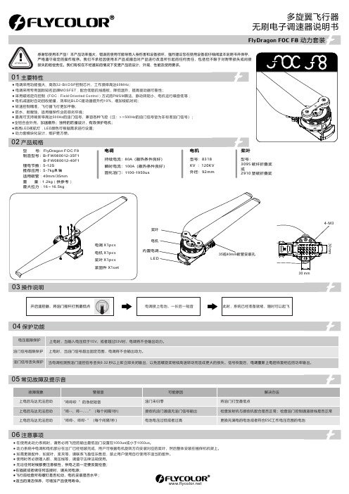
ATTENTION● 电调采用功能强大、高效32-Bit DSP 控制芯片,工作频率高达60MHz ;● 电调采用专用国际知名品牌MOSFET ,配合低阻抗线路板,降低温升,提高驱动器可靠性;● 采用磁场定向控制(FOC :Field Oriented Control )方式的PMSM 算法,脉动转矩小、电机运行噪音低等;● 电机减速时自动回收能量,效率比BLDC 驱动器提升约10%,增加续航时间;● 转速控制精准,飞行器飞行更加平稳;● 防水、耐腐蚀,适用植保作业的恶劣环境;● 最高可支持刷新率高达500Hz 的油门信号,兼容各种飞控(注:>=500Hz 的油门信号皆为非标准油门信号);●全铝合金外壳;,加速散热;独特的防撞设计,有效保护电机●高亮LED 夜航灯,LED 颜色可根据需求进行设置;● 动力套模块化设计,维护更方便。
持续电流:80A (散热条件良好)瞬时电流:100A (散热条件良好)固化油门:1100-1950u s型号:3095 碳纤折叠桨或2910 塑碳折叠桨型号:8318KV :120KV 外径:92mm电调电机桨叶型 号: FlyDragon FOC F8制造型号:B-FW080012-35F1 B-FW080012-40F1锂电节数:5-12S 推荐应用:5-7kg 单轴适用碳管:40mm/35mm 重 量:1.2kg (供参考)最大拉力:16~16.5kg此时,系统已经准备就绪,随时可以起飞电调接上电池,一长后一短音03 操作说明04 保护功能05 常见故障及提示音01 主要特性FlyDragon FOC F8 动力套装06 注意事项02 产品规格● 在使用此动力系统时,请务必将飞控的输出最低油门设置在1050us 或小于1050us 。
Infoprint 250 導入と計画の手引き 第 7 章ホスト
SUBNETMASK
255.255.255.128
Type of service...............: TOS
*NORMAL
Maximum transmission unit.....: MTU
*LIND
Autostart.....................:
AUTOSTART
*YES
: xx.xxx.xxx.xxx
: xx.xxx.xxx.xxx
*
(
)
IEEE802.3
60 1500
: xxxx
48 Infoprint 250
31. AS/400
IP
MTU
1
1
IPDS TCP
CRTPSFCFG (V3R2)
WRKAFP2 (V3R1 & V3R6)
RMTLOCNAME RMTSYS
MODEL
0
Advanced function printing............:
AFP
*YES
AFP attachment........................:
AFPATTACH
*APPC
Online at IPL.........................:
ONLINE
FORMFEED
*CONT
Separator drawer......................:
SEPDRAWER
*FILE
Separator program.....................:
SEPPGM
*NONE
Library.............................:
SQ仿真中的Tco与Tcom详解
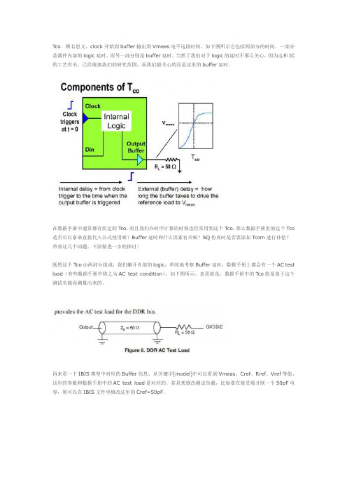
Tco,顾名思义,clock开始到buffer输出到Vmeas电平这段时间,如下图所示它包括两部分的时间,一部分是器件内部的logic延时,而另一部分则是buffer延时。
当然了我们对于logic的延时不那么关心,因为这和IC 的工艺有关,已经脱离我们的研究范围,而我们最关心的还是这里的buffer延时。
在数据手册中通常都有给定的Tco,而且我们在时序计算的时候也经常用到这个Tco,那么数据手册里的这个Tco 是否可以拿来直接代入公式使用呢?Buffer延时和什么因素有关呢?SQ仿真时是否要添加Tcom进行补偿?带着这几个问题,下面做进一步的探讨:既然这个Tco由两部分组成,我们撇开内部的logic,单纯地考察Buffer延时,数据手册上都会有一个AC test load(有些数据手册中称之为AC test condition),如下图所示。
意思就是:数据手册中的Tco值是基于这个测试负载而测量出来的。
再来看一下IBIS模型中对应的Buffer信息,从关键字[model]中可以看到Vmeas、Cref、Rref、Vref等值,这里的参数和数据手册中的AC test load是对应的。
若是想修改测试负载,比如要在接受端并联一个50pF电容,则可以在IBIS文件里修改这里的Cref=50pF。
似乎说到这里,还是不那么令人信服,那么我们下面就来仿真一下,验证buffer的延时是和负载相关的,并且Buffer的波形是基于数据手册中的AC test load而得到的。
在SigX中搭建拓扑结构如下,与数据手册中的AC test load等效。
设置驱动源,设置仿真参数,选择buffer delays为On-the-fly(From Library与On-the-fly的区别后面会讲解)仿真波形如下,从图中很容易看出蓝线(驱动端波形)和红线(buffer输出)重合这两个波形都上述拓扑结构中A3点的波形,那么就有点怪异了,都是同一点的波形,他们当然会重合!这个论点是成立的么?下面我们就来修改一下负载值,同时为了最大限度的抑制反射,设定传输线特性阻抗值与负载值相同,均为80ohm,修改后的拓扑结构如下其它的所有设置均保持与之前的拓扑设置一致,再来看一下波形很明显这里的Buffer波形与驱动端的波形没有重合,并且与Vmeas的交点也不在同一点。
zl38004中文资料_数据手册_IC数据表
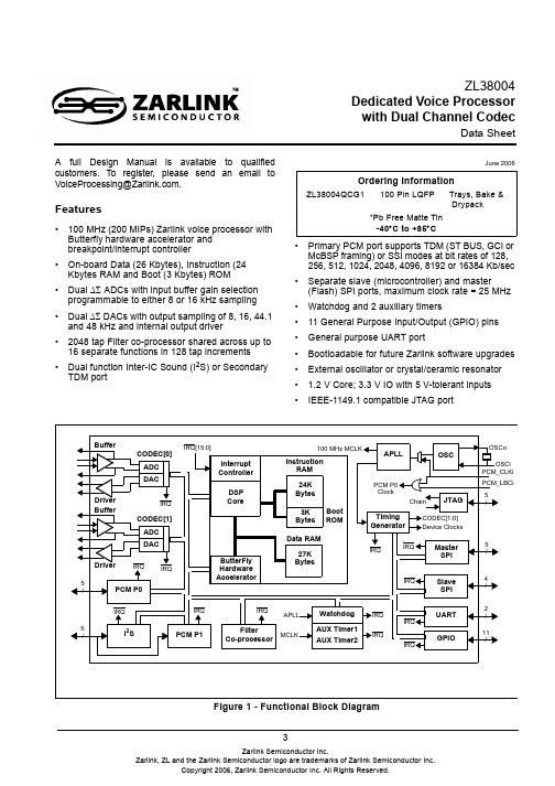
3A full Design Manual is available to qualifiedcustomers. To register, please send an email toVoiceProcessing@.Features •100MHz (200 MIPs) Zarlink voice processor withButterfly hardware accelerator andbreakpoint/interrupt controller•On-board Data (26 Kbytes), Instruction (24Kbytes RAM and Boot (3 Kbytes) ROM•Dual ∆Σ ADCs with input buffer gain selectionprogrammable to either 8 or 16kHz sampling•Dual ∆Σ DACs with output sampling of 8, 16, 44.1and 48kHz and internal output driver•2048 tap Filter co-processor shared across up to16 separate functions in 128 tap increments•Dual function Inter-IC Sound (I 2S) or SecondaryTDM port •Primary PCM port supports TDM (ST BUS, GCI or McBSP framing) or SSI modes at bit rates of 128, 256, 512, 1024, 2048, 4096, 8192 or 16384 Kb/sec •Separate slave (microcontroller) and master (Flash) SPI ports, maximum clock rate = 25MHz •Watchdog and 2 auxiliary timers •11 General Purpose Input/Output (GPIO) pins •General purpose UART port •Bootloadable for future Zarlink software upgrades •External oscillator or crystal/ceramic resonator• 1.2V Core; 3.3V IO with 5V-tolerant inputs•IEEE-1149.1 compatible JTAG port June 2006Ordering InformationZL38004QCG1100 Pin LQFPTrays, Bake & Drypack *Pb Free Matte Tin-40°C to +85°C ZL38004Dedicated Voice Processorwith Dual Channel CodecData SheetFigure 1 - Functional Block Diagram Data RAM DSP Boot ROM Instruction RAM 27K Bytes 24K Bytes 3K Bytes Interrupt Controller ButterFly Hardware Accelerator DACBufferADCDriverCODEC[0]IRQ[15:0]IRQ DACBufferADCDriverCODEC[1]IRQ PCM P0I 2S FilterCo-processor Watchdog Master SPI Slave SPIUARTGPIO AUX Timer1AUX Timer2IRQ IRQ APLL MCLK OSC JTAG IRQ APLL Timing Generator 100 MHz MCLK CODEC[1:0]IRQ IRQ IRQ IRQIRQ IRQ IRQ IRQ Device Clocks Chain OSCi OSCo PCM_CLKi PCM_LBCi 5/5/4/2/11/5/5/Core PCM P1PCM P0ClockZL38004Data Sheet Applications•Hands-free car kits•Full duplex speaker-phone for digital telephone•Echo cancellation for video conferences•Intercom Systems•Security Systems1.0 Functional DescriptionThe ZL38004 is a hardware platform designed to support advanced acoustic echo canceller (with noise reduction) firmware applications available from Zarlink Semiconductor. These applications are resident in external memory and are down-loaded by the ZL38004 resident boot code during initialization.The firmware products and manuals available at the release of this data sheet are: ZLS38500: Acoustic Echo Canceller with Noise Reduction for Hands-Free Car Kits; ZLS38501 Speakerphone. If these applications do not meet your requirements, please contract your local Zarlink Sales Office for the latest firmware releases.The ZL38004 Advanced Acoustic Echo Canceller with Noise Reduction platform integrates Zarlink’s Voice Processor (ZVP) DSP Core with a number of internal peripherals. These peripherals include the following:•Two independent ∆Σ CODECs•Two PCM ports - ST BUS, GCI, McBSP or SSI operation•An I2S interface port• A 2048 tap Filter Co-processor•Two Auxiliary Timers and a Watchdog Timer•11 GPIO pins• A UART interface• A Slave SPI port and a Master SPI port• A timing block that supports master and slave operation•An IEEE - 1149.1 compatible JTAG portThe DSP Core can process up to four 8-bit audio channels, two 16-bit audio channels or two 8-bit and one 16-bit audio channel. These audio channels may originate and terminate with the Σ∆ CODECs, or be communicated to and from the DSP Core through the PCM ports or the I2S port.ZL38004Data Sheet 2.0 Core DSP Functional BlockThe ZL38004 DSP Core functional block, illustrated in Figure 1, is made up of a DSP Core, Interrupt Controller, Data RAM, Instruction RAM, BOOT ROM and a ButterFly Hardware Accelerator. This block controls the timing (APLL and Timing Generator), peripheral interfaces and Filter Co-processor through a peripheral address/data/control bus and 16 prioritized interrupts.The ZL38004 implementation of DSP core and Filter Co-processor have been optimized to efficiently support voice processing applications. These applications are described in detail in the firmware manuals associated with this hardware platform.When an interrupt occurs the DSP core saves its current status and jumps to the address of the associated interrupt service routine.3.0 Codec[1:0]The ZL38004 has two 16-bit fully differential ∆Σ CODECs (CODEC 0/1) that can be programmed for 48kHz or 44.1kHz sampling, or to meet G.712 requirements at 8kHz sampling or G.722 at 16kHz sampling, see Figure 2. The ADC path consists of input signal pins C0/1_ADCi+ and C0/1_ADCi- (buffer output pins C0/1_BF0+ and C0/1_BFo-), which feed selectable Microphone Amplifier or Line Amplifier options. Once past the buffer the analog signal goes through a low pass antialiasing filter and to a 4th order feed-forward ∆Σ Modulator that produces a Pulse Density Modulated (PDM) signal. Next the PDM signal goes through a Low Pass Decimation Filter and then is converted into a 16-bit parallel word that can be read by the ZL38004 DSP (ADCout[15:0], Figures 2).The ZL38004 DSP will send 16-bit parallel word samples (DACin[15:0], Figure 2) to the DAC where they are converted to serial data and passed through an interpolation filter followed by a digital ∆Σ Modulator. The ∆ΣModulator generates PDM data, which then passes through a 32-tap FIR reconstruction filter. The reconstructed analog signal is then passed to a unity voltage gain differential output driver and to pins C0/1_DACo+ and C0/1_DACo-.The CODEC bias voltages are generated by an internal bandgap circuit (BIAS_VCM, BIAS_RF+ and BIAS_RF-).Each ZL38004 CODEC has two loopbacks. When activated, the input analog signal on pins C0/1_ADC+/- is looped around to C0/1_DAC+/-. Pulse Density Modulated (PDM) serial data from the ADC Analog ∆Σ Modulator output is looped around to the input of the DAC Reconstruction Filter. At the same time 16-bit parallel data is looped around from DACin[15:0] to ADCout[15:0]. PDM serial data from the DAC Digital ∆Σ Modulator is looped around to the input of the ADC Digital Low Pass Decimation Filter.When the Parallel Loopback is activated the input analog signal on pins C0/1_ADC+/- is looped around to the C0/1_DAC+/- output. 16-bit parallel data from the ADC Digital Low Pass Decimation Filter is looped around to the DAC Digital Low Pass Interpolation Filter. This data may be read by the DSP, but parallel data written to the DAC by the DSP will be lost.CODEC0 and CODCE1 of the ZL38004 may be powered down if they are not required. See firmware manual.ZL38004Data Sheet Figure 2 - CODEC Block Diagram4.0 PCM / I 2S PortsThe PCM ports 0 and 1 support data communication between an external peripheral device and the ZL38004 DSP Core using separate input (P0/1PCMi) and output (P0/1PCMo) serial streams with TDM (i.e., ST-BUS, GCI or McBSP) or SSI interface timing in both master or slave timing modes. Both PCM Ports 0 and 1 support the same functionality and modes of operation.PCM Port 1 pin functions are shared with the I 2S Port pin functions. The I 2S (Inter-IC Sound) port and PCM Port One share the same physical pins of the ZL38004. Selection of either I 2S port operation or PCM Port One operation is done through the Port One PCM/I 2S Select Register. See firmware manual.The I 2S port can be used to connect external Analog-to-Digital Converters or CODECs to the internal DSP . This port can operate in master mode, where the ZL38004 is the source of the port clocks, or slave mode, where the bit and sampling clocks (I 2S_SCK and I 2S_ LRCK) are inputs to the ZL38004. In I 2S port master mode the clock signal at output pin I 2S_LRCK is the sampling frequency (f S ), the clock signal at output I 2S_SCK is 32 x f S , and the clock signal at output I 2S_MCLK is 256 x f S . In I 2S port slave mode the relationship between the clock signal at input pin I 2S_LRCK and the clock signal at input I 2S_SCK must be 32 x f S . In slave mode the 256 x f S relationship between f S and the I 2S_MCLK is not mandatory, and the I 2S_MCLK output pin will be in a high impedance state.Access to the control and status registers associated with these ports is through the Slave SPI port or UART.BufferAnalog ∆ΣModulator Digital LP Decimation Filter Digital LP Interpolation Filter Antialiasing Filter Bias Generation 161616Reconstruction Filter & DriverDigital ∆ΣModulator 3.0720 MHz 2.8224 MHz Analog ClockAnalog Clock CODECLoopback CODEC LoopbackParallelBIAS_VCMBIAS_RF+BIAS_RF-C0/1_BFo+C0/1_BFo-C0/1_ADCi+C0/1_ADCi-C0/1_DACo+C0/1_DACo-DACin [15:0]ADCout [15:0]Analog Clock SelectZL38004PDMCODEC Loopback PDMZL38004Data Sheet 5.0 Host Microprocessor and Peripheral InterfacesThe ZL38004 provides 1 master SPI port (with 2 chip selects), 1 slave SPI ports and an UART. The master SPI port’s primary function is to access and external FLASH memory to download firmware to the ZL38004.The control/status registers and memory of the ZL38004 can be accessed (R/W) by an external host through the Slave SPI and the UART ports. Register/Memory read and write accesses are carried out through a series of port read and write accesses as follows:5.1 Master SPI (FLASH Port)The Master SPI port is used by the ZL38004 to access one or two peripheral devices (chip select signals SPIM_CS[1:0]). It supports both SPI and MICROWIRE modes of operation and can write up to 40 bits or read up to 32 bits in a single access. The Chip Select output signals may be programmed for a single access or burst access. All communication is MSB first and all pins of the master SPI port are outputs controlled by the ZL38004, except SPIM_MISO.5.2 Slave SPI (Host Port)The slave SPI port may be used by an external host microprocessor to access (Read/Write) the ZL38004 internal control/status registers and memory. Access is initiated when the external host makes signal SPIS_CS low and is ended when this signal goes high. The host will then apply a clock (maximum 25 MHz) to signal SPIS_CLK to clock data out of SPIS_MISO and in on SPIS_MOSI.5.3 UARTThe UART (Universal Asynchronous Receiver Transmitter) port may be used by an external host microprocessor to access (Read/Write) the ZL38004 internal control/status registers and memory. The ZL38004 DSP will set up the initial parameters of this port (i.e., master/slave, baud rate, stop bits, parity bit...) during the Boot process. After the device has been booted these port options can be changed as per the firmware manual.The UART port will support 8-bit data only with any combination of 1 start bit, 0 or 1 parity bit(s) and 1, 1.5 or 2 stop bit(s).The ZL38004 has 11 GPIO (General Purpose Input/Output) pins that can be individually configured as either input or output. These pins are intended for low frequency signalling.When a GPIO pin is defined as an input the state of that input pin is sampled with the internal master clock (Mclk = 100 MHz) and latched into the GPIO Read Register. This sampling can be stopped (Freeze) on an individual GPIO pin. Individual pins of GPIO[4:0] may have an internal pull-down resistor activated/deactivated and individual pins of GPIO[10:5] may have an internal pull-up activated/deactivated.Immediately after a power-on reset (RST pin) the GPIO pins are defined as inputs and their state is captured in the GPIO Start-Up Status Register. The state of this register is used by the Boot program to determine the base functionality and programming options of the device.Individual GPIO pins may also be defined as outputs with associated enable/disable (active/high impedance) control.。
GuiLin FeiYu Technology Incorporated Company 3-Axi

3-Axis Stabilized Handheld Gimbalfor Smartphone GuiLin FeiYu Technology Incorporated CompanyInstruction Manual V 1.21/4 inch screw holeIndicator StatusBlue light flashes once Blue light flashes twice Blue light constant onBlue light keeps flashing Blue light flashes three times Red light flashes three timesRed light keeps flashingRightYou can use the function button to switch the working mode, power on .”s n Portable bag X15Power on: Press and hold function button until the green light is on.Power off:Press and hold function button 6Start the App on your smartphone,follow the instructions to3. Modes / Functions6. Parameters4. Firmware UpgradeFunction ButtonDouble tapDouble tapSingle tapFunctionFunctionTrigger ButtonExplanationExplanationPanning Mode / Lock ModeLock ModeControl the App Lens ZoomPanning ResetPanning and Tilting ModeSingle tap to switch between panning mode and lock modeUnder panning and tilting mode, single tap to switch to lock modeMake the lens rotate 180 °Triple tapLong pressLong press +joystick up and downRotate 180°in horizontalReset the tilting axis of the gimbal to initial orientation andEnter the lock mode, release it to return to before modeRestore the initial follow state of the panningJoystick up and down to control the App lens zoom;left and right to control the panninginitial mode Quadruple tap ResetLong press untilthe red lightflashes quickly Single tap again to awake the gimbal, or triple tap to initialize the gimbal StandbyProhibit any user for any illegal purpose. Users will be responsible forall behaviors of purchase and use products.The Company assumes no liability for any risks related to or resultingfrom the debug and use of this product (including the direct, indirector third-party losses).For any unknown sources of using, we will not be at any services.The updating and changes of product firmware and program maycause changes in function descriptions in this user manual, pleaseread the instructions carefully before upgrading the firmware and usethe corresponding user manual.You can get the latest user manual from the official website:Feiyu Tech reserves the right to amend this manual and the termsand conditions of use the product at any time.Due to software and hardware improvements, your actual product mightdiffer from the descriptions and pictures in this user manual. You can getthe latest user manual from the official website.relevant programs for upgrading, including USB driver, Option 1: connect the gimbal with PC via micro USB cable, and then upgrade the firmware.then upgrade the firmware. (1)Feiyu ONYou can initialize your gimbal when:(1) when camera is not level(2) if not used for a long period of time(3) in case of extreme temperature variationsMode / Function Operation Instructions① Long press function button and release it until the redlight flash the gimbal enter standby mode, the blue lightwill flash 3 times periodically.② Lay the gimbal on a static flat surface and triple tapfunction button. Initialization is successful when the bluelight changes form constant on to flashing 3 timesperiodically.③ Click again to wake up the gimbal.。
啤酒行业专业英语词汇 汇总英汉
啤酒行业专业英语词汇啤酒类主要设备:Malt Handling System麦芽处理系统Received Hopper for Malt麦芽收料斗Malt Buffer Case麦芽缓冲箱Malt Hopper麦芽计量仓Rice Hopper大米计量仓Pre-mash Tun预糖化锅Rice Cooker糊化锅Brewhouse糖化间Mash Tun糖化锅Lauter Tun过滤槽Spent Grain Buffer Tank麦糟箱Spent Grain Silo麦糟罐Wort Sample Station麦汁取样台Wort Pre-run Buffer Tank麦汁暂存罐Weak Wort Tank弱麦汁罐Sparging Water Tank洗糟水罐Wort Kettle煮沸锅Internal Boiler(内)加热器Hop Dosing Platform酒花添加罐Energy Recovery System热能回收系统Energy Storage Tank能量储存罐Vapor Condenser蒸汽冷凝器Vacuum Evaporation Tank真空蒸发罐Vacuum Condenser真空冷凝器Whirlpool沉淀槽Trub Tank热凝固物收集罐Syrup Tank糖浆罐Sugar Dissolve Tank溶糖罐Wort Aeration System麦汁充氧系统Hot Water Tank热水罐Top plant罐顶装置Combined Platform联合平台Staircase塔架钢梯Aseptic Water Tank无菌水罐Unfiltered Buffer Tank过滤前缓冲罐Filtered Buffer Tank过滤后缓冲罐Pre- and Lst-Run Tank残酒罐Post-Cntrifugal Buffer Tank离心后缓冲罐Yeast Buffer Tank酵母缓冲罐Silica gel Reaction Tank硅胶溶解罐Kieselgur Storage Tank硅藻土储存罐Kieselgur Dosing Tank硅藻土添加罐Waste Yeast Tank废酵母罐Foam Catch Tank CO2除沫罐Crate Depalletizer箱垛卸机Unpacker卸箱机Packer装箱机Double-end Bottle Washer双端洗瓶机Filler and Crowner装瓶压盖机Crown Cork Conveyor输盖机Pasteurizer杀菌机Crate Washer洗箱机Labeller贴标机Bottle Conveyor输瓶系统Pressureless Conveyor Combiner and Distributor无压力输送系统Central Electrical Cabinet中央馈电柜Empty Bottle Inspector空瓶检验机Carlsberg Flask卡式罐Seed Tank种子罐Yeast Propagation Tank扩培罐The 2nd(3rd) Stage Yeast Propagation Tank(二)三级扩培罐Dosing Operating Platform加料操作台Yeast Storage Tank酵母储存罐Fermentation Tank发酵罐Bright Beer Tank (BBT) 清酒罐Deaerated Water Tank脱氧水罐Cold Water Tank冷水罐Chilled Water Tank冰水罐Great Caustic Tank大碱罐Hot Caustic Tank热碱罐Cold Caustic Tank冷碱罐Acid Tank酸罐Hot Water Tank CIP热水罐CIP tank CIP 罐Return Water Tank回收水罐Tubular Heat Exchanger列管换热器Condensate Recovery Tank冷凝水回收罐Flow Plate接管板Adjunct Dosing Tank辅料添加罐Condensate Caustic Tank浓碱罐Dissolve caustic tank溶碱罐Condensate Acid Tank浓酸罐Pipeline Filter管道过滤器Steam Distributor蒸汽分配器Compressed Air Buffer Tank压缩空气缓冲罐Hop Dosing Tank酒花添加罐Whirlpool沉淀槽Brew Water Tank酿造水罐Wort Cooler麦汁冷却器Mash Tun Pump 糖化醪液泵Candle Kieselguhr Filter烛式硅藻土过滤机Sparging water tank 洗糟水槽Mash-in device 调浆器部件及其他:Grain discharge flaps 糟门Grain raking 耕糟Raker 耕刀Grain removal 排糟Grain washing 洗糟Aspirating system 除尘系统Dimple jacket蜂窝夹套Wort aeration system 麦汁充氧系统Jet Coder喷码机Bottle Breakage破瓶率Residual Water残水Nominal Size公称尺寸/额定尺寸/毛尺寸Gripper抓头Air Consumption耗气量Proximity Switch接近开关Load of Floor地面负荷pix像素Sedimentation Tank沉积罐Cold Rolled Material 冷轧材料Glass-blasted 粒子磨光Load Cell 测压元件Lifting Lug/eye 吊环Thermometer Sleeve 温度计套管Nameplate 铭牌Anticorrosion Paint 防腐烂漆Acid Paste 酸洗膏Wet Pressure Test 湿压测试Food Grade Quality 食品等级Dye-Penetrant Method 染色渗透检验法/着色检验阀Precipitate Chalk 沉淀白垩/沉淀碳酸钙(一种测试方法)Plate heat exchanger 板式热交换器Actuator 致动器Groove 凹槽Conic Bottom锥底Brew house yield 糖化间收得率Water to grist ratio 水与投料比例Raw material configuration 原料配比Adjunct 辅料Extract for malt 麦芽浸出Extract for adjunct 辅料浸出Brew length 批次容量Unitank 交替式生物处理池Cast out 最终麦汁Malt hopper 麦芽料斗Pulley 滑轮Bucket 铲斗Malt elevator 麦芽提升机Vibrating screen 振动筛De-stonner 去石机Magnetic separator 磁选机En-grooved roll槽形滚筒Slide valve 滑阀Cylindro-conical case 圆锥形箱Head 扬程(单位为MWC)Centrifugal pump 离心泵Working volumn 有效容积Sight glass 视镜Light glass 光镜Cladding 包皮Resin 树脂Vent stack 排气筒Snug fit 滑合座Descale 除垢Aeration充氧装置Sterile air filtration system 无菌空气过滤系统Flow meter 流量计Fine adjustment valve 微调阀门Primary air filtration 初级空气过滤Polypropylene 聚丙烯Heating media 加热介质Hot caustic tank 热碱罐Common base connection 共基极连接Yeast propagation 酵母扩培Spray ball清洗球Dull polish 磨砂Cartridge filter element 放热过滤元件Glycol 乙二醇Bunging apparatus办槽装置Samplingvalve 取样阀Insulation 保温(绝缘)Free ladder 活动梯子Vapour stack 排汽筒NDT 无损探伤Vitreous utensil 玻璃容器Electronic balance 电子天平Counter balance 托盘天平Barley grader 大麦分选机Constant water bath pan 恒温水浴锅Increase force mixer 增力搅拌机Saccharification instrument 糖化仪器Refax machine 煮沸色度回流器(ZF) Electronic evaporator 电蒸馏器Electronic stove 电炉Chroma instrument 色度仪Baking box 烘箱Hopping milling 酒花磨Conductibility apparatus 电导仪Residual chlorine meter快速余氨(比色计)Iron stand 铁架台Titrate stand 滴定台Turbidity meter 浊度仪Culture dish 培养皿Shaking bed 旋摇床Electronic analytic balance 电子分析天平Spectra photometer 分光光度仪Condensate water 冷凝水Motor retarding device 电机减速器Dish head 封头Mash pump 醪液泵Reinforce plate 筋板Sieve plate 筛板Feed valve 进料阀Buffering pump 缓冲罐Wort kettle 麦汁煮沸锅Staff gauge 标尺Shell 锅身(筒节)Manhole人孔Backing plate 垫板Close plate 封板Base plate 挡板,护板Whirlpool setting tank 旋流沉淀槽Ring plate 环板Malt outlet pipe 麦汁出口管CIP feeding pump CIP进料泵Brew/batch批次Filling 填料Fermentation 发酵Cooling 冷却Heating 加热Grain silo麦仓Weighing machine 称重器Wet malt milling machine 湿麦芽粉碎机Soft water 软水Thermal load 热应力Watch dog time 监控时间Enzyme 酶制剂Hop dosing 酒花添加Bitter substance 苦味质Isomerization 异构化作用PH- value PH值Acidifying machine 浸酸机压滤机 filter pressMicro-switch 微控开关Circuit 电路Terminal 端口Surface finish 表面处理Dust collector 集尘器Baghouse 集尘室(尘渣室)Powder discharge 除尘器Bagging system 打包系统Fluidbed 流化床(沸腾层)Collar 翻边Shaking bed 摇床Air distributor 空气分配器Bucket Elevator斗式提升机Scraper conveyor刮板输送机Steel Silo for Malt钢板仓Impack Plate Flow meter冲板式流量计Rush-board Flow MeterHand-Operated Slide Valve手动闸板阀Pneumatic Slide Valve气动闸板阀Magnetic Separator磁选机(电磁除铁器)Malt Vibrating Sieve麦芽振动筛Plane Gyrating and Oscillating Sieve Malt Wet Mill麦芽湿粉碎机Steeping Conditioning Chute 浸泡槽Steeping Liquor 浸渍液Sight Glass视镜Steeping Liquor Separator 喷水装置Steeping Liquor Dosing Device 水分离器Spray Ball洗球Holding Device for Roller 粉碎轴支撑装置Feed Roller 供料轴Geared Motor 齿轮电机Wear Jaws 摩擦挡板Crushing Roller 粉碎轴Drive Motor 驱动电机Mash Water Feeding and Dosing Device 酿造水计量添加装置Side Coating 端盖Water Shortage Safety Device 缺水安全装置Thick Matter Pump 高浓度泵Emergency Stop Switch 急停开关Dust Catcher With Impulse 脉冲除尘器Exhaust Fan 排气扇Dust Collection Cover 吸尘罩Received Hopper for Corn 玉米收料斗Grid 网格Jacket夹套Insulation保温层Cladding包皮Manhole人孔Free Ladder活动梯子Agitator搅拌器Liquid Catching Tray集水盘Vapour Stack 排汽筒Rivet 铆钉Access Door 通道门,人孔门,人孔Bearing Grate 格栅架False Bottom 假底Mold Release 脱膜OD 外径ID 内径Vacuum Valve 真空阀Pressure Transmitter / Sensor/ Transducer 压力传感器Corridor 走廊Enzym 酶制剂Displacement Pump 容积式泵Centrifugal Pump 离心泵Measuring Pump 计量泵Bottom Seat Valve 底座阀Purge Gas 惰性气体Built-in 插入式管Pressure Shock Absorber 压力减震器Washer 垫圈Gasket 垫片Trap Filter/ Particulate Trap 离子捕捉器Self- Priming 自吸式Dimple Jacket 蜂窝夹套Aeration Lance 充气杆Level Switch 液位开关Halogen Light 卤素灯/卤光灯Change-over Valve 换向阀/ 切换阀Self-Closing Valve 自锁阀Slide Valve 滑阀Touch Screen/Panel 触摸屏/ 人机界面Solenoid Valve 电磁阀Weighing Sensor/Transmitter 称重传感器Conductance Sensor 电导率传感器/测定仪(EPDM)Ethylene Propylene Terpolymer Rubber 三元乙丙橡胶Three-phase Voltage 三相电压Deaeration Tower 脱氧塔Disinfectant Dosing System 消毒剂添加系统Output/Input Module 输出/输入模块Indication Lamp 指示灯IPC 工控机Mash-in Water 调浆水Switching Amplifier 转换/开关放大器Probe 探头Feed Roller 进料辊/喂料辊Detection Limit 检测极限Microwave Limit Switch 微波开关Frequency Converter 变频率器Level Indicator 液位指示器On-line Oxygen Dissolving Meter 在线溶氧仪安装工具等:jack千斤顶rack-jack齿条千斤顶oil jack / hydraulic jack油压千斤顶screw jack螺旋千斤顶fork truck叉车tackle滑车shackle卸扣electric welding machine电焊机argon arc welding machine氩弧焊机wheel cutting machine砂轮切割机angle grinder角磨机electric drill手电钻reeling machine卷扬机steel rope钢丝绳chain block手拉葫芦jute rope / hemp rope麻绳pliers wire钳线acetylene乙炔Sparging Device 洗糟装置Mash Distribution Device 醪液分配装置Flange 法兰Spent Grain Removal Device 麦糟排出装置Wet Spent Grain Discharge Flap 麦糟出口翻板阀Spent Grain Case 连接箱Raking Machine 耕槽装置Filtration Bed 槽床Clamp Coupling 联轴器Drive shaft驱动轴Transducer 变频器,传感器Pump Lautering System 泵过滤系统Non-return Flap 止回瓣Horizontal Tank 卧式罐Rock Wool/ Mineral Wool 岩棉Two-Level Wort Deflector 双层麦汁导流罩Rotating Spraying Nozzle 旋转喷嘴Trub Discharge 热凝固物清洗装置Trub Collecting Tank 热凝固物收集罐Corrugated Plate 波纹板Dish Head/ Torispherical Head 蝶形封头Booster Heat Exchanger 过热水换热器Impeller 糖化醪液泵Pneumatic Butterfly Valve 气动蝶阀Manual Butterfly Valve 手动蝶阀Ball Valve 球阀Stop Valve 截止阀Drain Valve 疏水阀Check Valve 止回阀Pole Valve 顶杆阀Stem Valve 杆阀Pneumatic Membrane Regulation Valve 气动薄膜调节阀Sample Valve 取样阀Pressure Release Valve 减压阀Flow Meter 流量计Clamp 管卡,卡箍PU Insulation 聚氨酯保温Skirt 裙座Cool Medium / Coolant 冷媒Pickle 酸洗Passivate 钝化Sand Blasting 喷砂Nozzle 接口,管口Cooling Section 冷带Cable Pipe 电缆管Polyurethane foam (PU) 聚氨酯泡沫Foaming 发泡Forming 鼓胀MCC(Motor Control Center) 电机控制中心Terminal 端子Power Distribution Circuit 配电回路Power Distribution Cabinet 配电柜Air Blower 排风机Cable Tray 电缆桥架Bus:3-phase 5-wire system 母线:三相五线制SCADA software 组态软件 Configuration Software?? Programming Software 编程软件LCD Screen 液晶显示器Ethernet Card 以太网卡Casting 铸造Forging 锻造cable tray桥架Structural steel 结构钢/ 组织钢/ 钢架Heat treating furnace 热处理炉nternational Standard for Phytosanitary Measures(ISPM)国际植物检疫措施标准Fumigation/disinfection certificate 熏蒸证书Repacking 重装Dead freight 空舱Return of goods / rejection of goods退货General Intra-Community License 欧共体内一般性许可Intra-Community Supply 欧共体内供给Intra-Community Acquisition 欧共体内取得测量工具:Pressure gauge 压力计Vernier caliper 游标卡尺Micrometer 千分尺,测微计Tape measure 卷尺Square 直角尺Ferrite testing gauges 铁酸盐测试计Tubular heat exchanger 管壳式换热器Head-channel 头部管箱Head-bonnet 管箱(封头上的)Head flange-channel(bonnet)头部管箱法兰Stationary Tubesheet 固定管板Floating tubesheet 浮动管板Flange-rear head end 尾部管箱法兰Expansion joint 膨胀节Floating head cover浮头盖Floating head cover flange 浮头盖法兰Packing box 填料函Packing gland 填料压盖Lantern ring 套环Tierod 拉杆Spacer 定距管 locating rodTransverse baffle 折流板Impingement plate 防冲板Support plate 支撑板Pass partition 分程板Support saddle 固定鞍座,职称鞍座Backing device 衬垫装置Tube pass(tube-side pass)管程Shell pass (shell-side pass) 壳程焊接方面Acetylene 乙炔Ampere 安培 (电流)Angle welding, corner welding,fillet welding 角焊Arc 电弧Argon arc welding 氩弧焊接Butt welding 对接焊接,角焊, 填角焊, 贴角焊Bead welding,overlaying weld 堆焊Fillet weld 填角焊接Laser beam welding 雷射光焊接Spot welding 点焊Skip welding 跳焊automatic weld自动焊接arc-weld电弧焊backing groove of weld焊缝反面坡口all-around weld整周焊connective weld联系焊continuous weld连续焊flat fillet weld平角焊gas-pressure weld气压焊intermittent weld断续焊; 断续焊缝pressure weld压焊pressure-tight weld气密焊; 密封焊道single-pass weld单道焊工程图纸词汇:Not to scale (NTS)不按比例Data sheet数据表corrosion allowance腐蚀裕量medium介质activated pressure起跳压力filling ratio充装系数heating transfer surface传热面积gas-tight test气密(耐压测试)pneumatic test气压测试hydraulic test液压测试grade牌号(grade of welding rod焊条牌号)welding rod焊条welding wire焊丝welding seam焊缝aseptic air无菌空气butt joint平接头cladding包皮top flange罐顶法兰top plant罐顶装置washer垫圈gasket垫片bolt螺栓nut螺母thread螺纹hexagonal thread六角螺纹screw螺丝rivet铆钉nameplate铭牌weighing machine称重器closing board封板adjustable leg可调节支腿mineral wool, rock wool岩棉coolant, cool medium冷媒condensate water冷凝水blind flange法兰盖blind rivet抽芯铆钉seal ring密封圈silicon rubber硅橡胶reinforcing ring加强圈reinforcing rib加强筋reducer pipe变径管pressure transmitter压力传感器temperature transmitter温度传感器section截面top view俯视图torispherical head蝶形封头coil pipe盘管liquid ammonia液氨Mild steel 软钢,低碳钢Polythene 聚乙烯clamp, hoop卡箍Body 阀体Bonnet 阀盖Disc 阀瓣nut 螺母Screw 螺栓Stem 阀杆Stem Mut 阀杆螺母Stem seal 填料Wedge Disc 闸板Nominal bore 公称通径Nominal Pressure 公称压力Nominal size 公称尺寸Mechanical capacity 机械性能Max. Discharging Capacity 最大排水量 Max. Operating Temperature 最高工作温度Max. Allowable Temperature 最高允许温度Max. Allowable Pressure 最高允许压力blind flange法兰盖,盲板法兰阀门种类:Air valves 空气阀门Stop valves 截止阀Throttle Valves 节流阀Auxiliary valves 辅助(副)阀Brake valves 制动阀Butterfly Type Non-slam Check 蝶式缓冲止回阀Butterfly Valves with Gear Actuator 蜗轮传动蝶阀Butt welding valves 对焊连接阀Cock 二通Decompression valves 泄压阀Drainage valves 排水阀Stop Valves截止阀Stop Valves 截止阀T-Cock 三通Triple (tee) valves 三通阀Two-way valves 二通阀Under Water Pumps 液下泵Vacuum Pumps 水力喷射器(真空泵)Vertical Lift Check Valves 立式止回阀Wafer Check Valves 对夹式止回阀Wafer plate valves 对夹蝶板阀Ball Valves球阀Deceleration valves 减速阀Gate valve 闸阀Emergency Cut-off Valves 紧急切断阀Exhaust valves 排气阀Float Type Steam Trap 浮球式疏水阀Flange Ball Valves 法兰球阀Flange Gate Valves 法兰闸阀Gauge Valves 仪表阀Hand-operated valves / manual valve手动阀Butterfly Valves 碟阀Hydraulic relay valves 液压继动阀Check Valves止回阀Limit valves 限位阀Lining Ball Valves 衬里球阀Liquid Indicator/level indicator液位计Centrifugal Pumps离心泵 Pressure valve 压力(増压)阀Piping Pumps 管道泵Piping Safety Valves 管道安全阀Draining Valves排污阀Restrictor Valves/throttle或节流阀)Safety Valves 安全阀Screw Pumps 螺杆泵Scum Gate Valves 排渣闸阀。
Skyworks Solutions PCIe 时钟缓冲器文档说明书
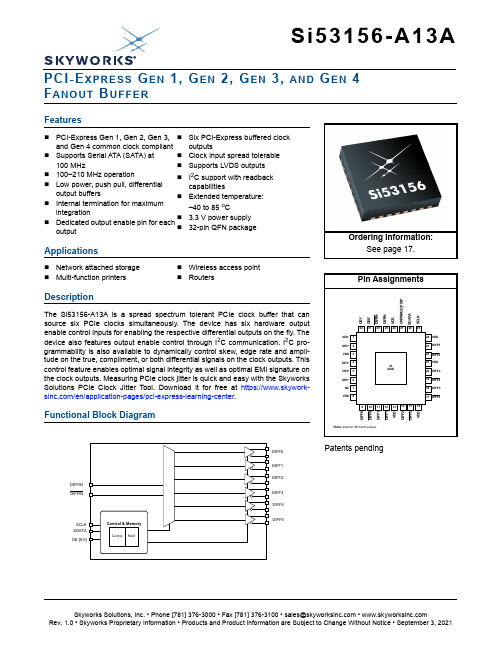
Si53156-A13APCI-E XPRESS G EN 1, G EN 2, G EN 3, AND G EN 4 F ANOUT B UFFERFeaturesApplicationsDescriptionThe Si53156-A13A is a spread spectrum tolerant PCIe clock buffer that can source six PCIe clocks simultaneously. The device has six hardware output enable control inputs for enabling the respective differential outputs on the fly. The device also features output enable control through I 2C communication. I 2C pro-grammability is also available to dynamically control skew, edge rate and ampli-tude on the true, compliment, or both differential signals on the clock outputs. This control feature enables optimal signal integrity as well as optimal EMI signature on the clock outputs. Measuring PCIe clock jitter is quick and easy with the Skyworks Solutions PCIe Clock Jitter Tool. Download it for free at https:///en/application-pages/pci-express-learning-center .Functional Block Diagram⏹PCI-Express Gen 1, Gen 2, Gen 3, and Gen 4 common clock compliant ⏹Supports Serial ATA (SATA) at 100MHz ⏹100–210MHz operation ⏹Low power, push pull, differential output buffers ⏹Internal termination for maximum integration⏹Dedicated output enable pin for eachoutput⏹Six PCI-Express buffered clock outputs⏹Clock input spread tolerable ⏹Supports LVDS outputs ⏹I 2C support with readback capabilities⏹Extended temperature: –40 to 85o C⏹3.3V power supply ⏹32-pin QFN package⏹Network attached storage ⏹Multi-function printers⏹Wireless access point ⏹RoutersDIFFIN DIFFINSCLK SDATA OE [5:0]DIFF0DIFF1DIFF2DIFF3DIFF4DIFF5Patents pendingOrdering Information:See page 17.Si53156-A13A2SkyworksSolutions,Inc.•Phone[781]376-3000•Fax[781]376-3100•*********************•Si53156-A13A T ABLE OF C ONTENTSSection Page1. Electrical Specifications . . . . . . . . . . . . . . . . . . . . . . . . . . . . . . . . . . . . . . . . . . . . . . . . . . .42. Functional Description . . . . . . . . . . . . . . . . . . . . . . . . . . . . . . . . . . . . . . . . . . . . . . . . . . . .72.1. OE Pin Definition . . . . . . . . . . . . . . . . . . . . . . . . . . . . . . . . . . . . . . . . . . . . . . . . . . . . .72.2. OE Assertion . . . . . . . . . . . . . . . . . . . . . . . . . . . . . . . . . . . . . . . . . . . . . . . . . . . . . . . .72.3. OE Deassertion . . . . . . . . . . . . . . . . . . . . . . . . . . . . . . . . . . . . . . . . . . . . . . . . . . . . . .73. Test and Measurement Setup . . . . . . . . . . . . . . . . . . . . . . . . . . . . . . . . . . . . . . . . . . . . . . .84. Control Registers . . . . . . . . . . . . . . . . . . . . . . . . . . . . . . . . . . . . . . . . . . . . . . . . . . . . . . . .104.1. I2C Interface . . . . . . . . . . . . . . . . . . . . . . . . . . . . . . . . . . . . . . . . . . . . . . . . . . . . . . .104.2. Data Protocol . . . . . . . . . . . . . . . . . . . . . . . . . . . . . . . . . . . . . . . . . . . . . . . . . . . . . .105. Pin Descriptions: 32-Pin QFN . . . . . . . . . . . . . . . . . . . . . . . . . . . . . . . . . . . . . . . . . . . . . .156. Ordering Guide . . . . . . . . . . . . . . . . . . . . . . . . . . . . . . . . . . . . . . . . . . . . . . . . . . . . . . . . . .177. Package Outline . . . . . . . . . . . . . . . . . . . . . . . . . . . . . . . . . . . . . . . . . . . . . . . . . . . . . . . . .188. Land Pattern . . . . . . . . . . . . . . . . . . . . . . . . . . . . . . . . . . . . . . . . . . . . . . . . . . . . . . . . . . . .19 Document Revision History . . . . . . . . . . . . . . . . . . . . . . . . . . . . . . . . . . . . . . . . . . . . . . . . .21 SkyworksSolutions,Inc.•Phone[781]376-3000•Fax[781]376-3100•*********************•3Si53156-A13A4SkyworksSolutions,Inc.•Phone[781]376-3000•Fax[781]376-3100•*********************•1. Electrical SpecificationsTable 1. DC Electrical SpecificationsParameterSymbol Test ConditionMin Typ Max Unit 3.3V Operating Voltage VDD core 3.3 ± 5% 3.135— 3.465V 3.3V Input High Voltage V IH Control input pins 2.0—V DD + 0.3V 3.3V Input Low Voltage V IL Control input pins V SS – 0.3—0.8V Input High Voltage V IHI2C SDATA, SCLK 2.2——V Input Low VoltageV ILI2C SDATA, SCLK —— 1.0V Input High Leakage Current I IH Except internal pull-down resistors, 0 < V IN < V DD ——5μA Input Low Leakage Current I IL Except internal pull-up resistors, 0 < V IN < V DD–5——μA 3.3V Output High Voltage (Single-Ended Outputs)V OH I OH = –1 mA 2.4——V 3.3V Output Low Voltage (Single-Ended Outputs)V OL I OL = 1 mA——0.4V High-impedance Output CurrentI OZ –10—10μA Input Pin Capacitance C IN 1.5—5pF Output Pin Capacitance C OUT ——6pF Pin Inductance L IN ——7nH Power Down Current I DD _PD ——1mA Dynamic Supply Current in Fanout ModeI DD_3.3VDifferential clocks with 5” traces and 2pF load, fre-quency at 100MHz——45mASi53156-A13ASkyworksSolutions,Inc.•Phone[781]376-3000•Fax[781]376-3100•*********************• 5Table 2. AC Electrical SpecificationsParameterSymbolConditionMinTypMaxUnitDIFFIN at 0.7V Input Frequency Rangef in 100—210MHzRising and Falling Slew Rates for Each Clock Output Signal in a Given Differential Pair T R /T FSingle ended measurement: V OL = 0.175 to V OH = 0.525V(Averaged)0.6—4 V/nsDifferential Input High Voltage V IH 150——mV Differential Input Low Voltage V IL ——–150mV Crossing Point Voltage at 0.7V SwingV OX Single-ended measurement 250—550mV Vcross Variation over all edges V OX Single-ended measurement——140mV Differential Ringback Voltage V RB –100—100mV Time before ringback allowed T STABLE 500——ps Absolute maximum input voltage V MAX —— 1.15V Absolute minimum input voltage V MIN –0.3——V Duty Cycle for Each Clock Output Signal in a Given Differential Pair T DCMeasured at crossing point V OX 45—55%Rise/Fall Matching T RFMDetermined as a fraction of 2x (T R – T F )/(T R + T F )——20%DIFF at 0.7V Duty Cycle T DC Measured at 0V differential 45—55%Clock Skew T SKEW Measured at 0V differential——50ps Additive Peak JitterPk-Pk 0—10ps Additive PCIe Gen 2 Phase JitterRMS GEN210kHz < F < 1.5 MHz 0—0.5ps 1.5MHz< F < Nyquist Rate0—0.5ps Additive PCIe Gen 3 Phase Jitter RMS GEN3Includes PLL BW 2–4MHz(CDR = 10MHz)0—0.10ps Additive PCIe Gen 4 Phase Jitter RMS GEN4PCIe Gen 4——0.10ps Additive Cycle to Cycle Jitter T CCJ Measured at 0V differential ——50ps Long-term Accuracy L ACC Measured at 0V differential ——100ppm Rising/Falling Slew rate T R / T F Measured differentially from±150mV 2.5—8V/ns Crossing Point Voltage at 0.7V SwingV OX300—550mVNotes:1.Gen 4 specifications based on the PCI-Express Base Specification 4.0 rev. 0.5.2. Download the Skyworks Solutions PCIe Clock Jitter Tool at https:///en/application-pages/pci-express-learning-center .Si53156-A13A6SkyworksSolutions,Inc.•Phone[781]376-3000•Fax[781]376-3100•*********************•Enable/Disable and Setup Clock Stabilization from Power-UpT STABLEMeasured from the point when both V DD and clock input arevalid–—5msStopclock Set-up TimeT SS10.0——nsTable 3. Absolute Maximum ConditionsParameterSymbol Condition Min Typ Max Unit Main Supply Voltage V DD_3.3VFunctional —— 4.6V Input Voltage V IN Relative to V SS –0.5— 4.6V DC Temperature, StorageT S Non-functional –65—150°C Industrial Temperature, Operating AmbientT A Functional –40—85°C Commercial Temperature, Operating AmbientT A Functional 0—85°C Temperature, Junction T J Functional ——150°C Dissipation, Junction to Case ØJC JEDEC (JESD 51)——17°C/W Dissipation, Junction to Ambient ØJA JEDEC (JESD 51)——35°C/W ESD Protection (Human Body Model)ESD HBM JEDEC (JESD 22 - A114)2000——VFlammability RatingUL-94UL (Class)V–0Note:Multiple Supplies: The voltage on any input or I/O pin cannot exceed the power pin during power-up. Power supplysequencing is not required.Table 2. AC Electrical Specifications (Continued)ParameterSymbolConditionMinTypMaxUnitNotes:1.Gen 4 specifications based on the PCI-Express Base Specification 4.0 rev. 0.5.2. Download the Skyworks Solutions PCIe Clock Jitter Tool at https:///en/application-pages/pci-express-learning-center .Si53156-A13A 2. Functional Description2.1. OE Pin DefinitionThe OE pins are active high inputs used to enable and disable the output clocks. To enable the output clock, the OE pin needs to be logic high and the I2C output enable bit needs to be logic high. There are two methods to disable the output clocks: the OE is pulled to a logic low, or the I2C enable bit is set to a logic low. The OE pins are required to be driven at all times even though they have an internal 100k resistor.2.2. OE AssertionThe OE signals are active high inputs used for synchronous stopping and starting the DIFF output clocks respectively while the rest of the clock generator continues to function. The assertion of the OE signal by making it logic high causes stopped respective DIFF outputs to resume normal operation. No short or stretched clock pulses are produced when the clock resumes. The maximum latency from the assertion to active outputs is no more than two to six output clock cycles.2.3. OE DeassertionWhen the OE pin is deasserted by making it logic low, the corresponding DIFF output is stopped, and the final output state is driven low.SkyworksSolutions,Inc.•Phone[781]376-3000•Fax[781]376-3100•*********************•7Si53156-A13A8SkyworksSolutions,Inc.•Phone[781]376-3000•Fax[781]376-3100•*********************•3. Test and Measurement SetupThis diagram shows the test load configuration for differential clock signals.Figure 1.0.7V Differential Load ConfigurationFigure 2.Differential Measurement for Differential Output Signals(for AC Parameters Measurement)Si53156-A13AFigure3.Single-Ended Measurement for Differential Output Signals(for AC Parameters Measurement)SkyworksSolutions,Inc.•Phone[781]376-3000•Fax[781]376-3100•*********************•9Si53156-A13A4. Control Registers4.1. I2C InterfaceTo enhance the flexibility and function of the clock buffer, an I2C interface is provided. Through the I2C Interface, various device functions are available, such as individual clock output enable. The registers associated with the I2C Interface initialize to their default setting at power-up. The use of this interface is optional. Clock device register changes are normally made at system initialization, if any are required. Power management functions can only be programed in program mode and not in normal operation modes.4.2. Data ProtocolThe I2C protocol accepts byte write, byte read, block write, and block read operations from the controller. For block write/read operation, access the bytes in sequential order from lowest to highest (most significant bit first) with the ability to stop after any complete byte is transferred. For byte write and byte read operations, the system controller can access individually indexed bytes.The block write and block read protocol is outlined in Table4 on page10 while Table5 on page11 outlines byte write and byte read protocol. The slave receiver address is 11010110 (D6h).Table 4. Block Read and Block Write ProtocolBlock Write Protocol Block Read Protocol Bit Description Bit Description1Start1Start8:2Slave address—7 bits8:2Slave address—7 bits9Write 9Write 10Acknowledge from slave10Acknowledge from slave18:11Command Code—8 bits18:11Command Code–8 bits19Acknowledge from slave19Acknowledge from slave27:20Byte Count—8 bits20Repeat start28Acknowledge from slave27:21Slave address—7 bits36:29Data byte 1–8 bits28Read = 137Acknowledge from slave29Acknowledge from slave45:38Data byte 2–8 bits37:30Byte Count from slave—8 bits46Acknowledge from slave38Acknowledge....Data Byte/Slave Acknowledges46:39Data byte 1 from slave—8 bits....Data Byte N–8 bits47Acknowledge....Acknowledge from slave55:48Data byte 2 from slave—8 bits....Stop56Acknowledge....Data bytes from slave/Acknowledge....Data Byte N from slave—8 bits....NOT Acknowledge....Stop10SkyworksSolutions,Inc.•Phone[781]376-3000•Fax[781]376-3100•*********************•Table 5. Byte Read and Byte Write ProtocolByte Write Protocol Byte Read ProtocolBit Description Bit Description1Start1Start8:2Slave address–7 bits8:2Slave address–7 bits9Write 9Write 10Acknowledge from slave10Acknowledge from slave18:11Command Code–8 bits 18:11Command Code–8 bits19Acknowledge from slave19Acknowledge from slave27:20Data byte–8 bits20Repeated start28Acknowledge from slave27:21Slave address–7 bits29Stop28Read29Acknowledge from slave37:30Data from slave–8 bits38NOT Acknowledge39StopControl Register 0.Byte 0Bit D7D6D5D4D3D2D1D0 NameType R/W R/W R/W R/W R/W R/W R/W R/W Reset settings = 00000000Bit Name Function7:0ReservedControl Register 1.Byte 1Bit D7D6D5D4D3D2D1D0 Name DIFF0_OE DIFF1_OE DIFF2_OE Type R/W R/W R/W R/W R/W R/W R/W R/W Reset settings = 00010101Bit Name Function7:5Reserved4DIFF0_OE Output Enable for DIFF0.0: Output disabled.1: Output Enabled.3Reserved2DIFF1_OE Output Enable for DIFF1.0: Output disabled.1: Output enabled.1Reserved0DIFF2_OE Output Enable for DIFF2.0: Output disabled.1: Output enabled.Control Register 2.Byte 2Bit D7D6D5D4D3D2D1D0 Name DIFF3_OE DIFF4_OE DIFF5_OEType R/W R/W R/W R/W R/W R/W R/W R/W Reset settings = 11100000Bit Name Function7DIFF3_OE Output Enable for DIFF3.0: Output disabled.1: Output enabled.6DIFF4_OE Output Enable for DIFF4.0: Output disabled.1: Output enabled.5DIFF5_OE Output Enable for DIFF5.0: Output disabled.1: Output enabled.4:0ReservedControl Register 3.Byte 3Bit D7D6D5D4D3D2D1D0 Name Rev Code[3:0]Vendor ID[3:0]Type R/W R/W R/W R/W R/W R/W R/W R/W Reset settings = 00001000Bit Name Function7:4Rev Code[3:0]Program Revision Code.3:0Vendor ID[3:0]Vendor Identification Code.Reset settings = 00000110Reset settings = 11011000Control Register 4.Byte 4Bit D7D6D5D4D3D2D1D0Name BC[7:0]TypeR/WR/WR/WR/WR/WR/WR/WR/WBit Name Function7:0BC[7:0]Byte Count Register.Control Register 5.Byte 5BitD7D6D5D4D3D2D1D0Name DIFF_Amp_Sel DIFF_Amp_Cntl[2]DIFF_Amp_Cntl[1]DIFF_Amp_Cntl[0]TypeR/WR/WR/WR/WR/WR/WR/WR/WBit Name Function7DIFF_Amp_SelAmplitude Control for DIFF Differential Outputs.0: Differential outputs with Default amplitude.1: Differential outputs amplitude is set by Byte 5[6:4].6DIFF_Amp_Cntl[2]DIFF Differential Outputs Amplitude Adjustment.000: 300mV 001: 400mV 010: 500mV 011: 600mV 100: 700mV 101: 800mV 110: 900mV 111: 1000mV5DIFF_Amp_Cntl[1]4DIFF_Amp_Cntl[0]3:0Reserved5. Pin Descriptions: 32-Pin QFNFigure 4.32-Pin QFNTable 6. Si53156-A13A 32-Pin QFN DescriptionsPin #Name TypeDescription1VDD PWR 3.3V power supply.2OE2I,PUActive high input pin enables DIFF2 (internal 100k Ω pull-up).Refer to Table 1 on page 4 for OE specifications.3VDD PWR 3.3V Power Supply 4OE3I,PU Active high input pin enables DIFF3 (internal 100k Ω pull-up).Refer to Table 1 on page 4 for OE specifications.5OE4I,PU Active high input pin enables DIFF4 (internal 100k Ω pull-up).Refer to Table 1 on page 4 for OE specifications.6OE5I,PU Active high input pin enables DIFF5 (internal 100k Ω pull-up).Refer to Table 1 on page 4 for OE specifications.7NC NCNo connect.8VDD PWR 3.3V power supply.9DIFF0O, DIF 0.7V, 100MHz differential clock.10DIFF0O, DIF 0.7V, 100MHz differential clock.11DIFF1O, DIF 0.7V, 100MHz differential clock.VDD OE2*VDD OE3*OE5*D I F F 0D I F F 0D I F F 1D I F F 1V D DD I F F 2G D _P D B *VDDD I F F 2V D D*Note: Internal 100 kohm pull-up.12DIFF1O, DIF 0.7V, 100MHz differential clock.13VDD PWR 3.3V power supply.14DIFF2O, DIF 0.7V, 100MHz differential clock.15DIFF2O, DIF 0.7V, 100MHz differential clock.16VDD PWR 3.3V power supply.17DIFF3O, DIF 0.7V, 100MHz differential clock.18DIFF3O, DIF 0.7V, 100MHz differential clock.19DIFF4O, DIF 0.7V, 100MHz differential clock.20DIFF4O, DIF 0.7V, 100MHz differential clock.21VDD PWR 3.3V power supply.22DIFF5O, DIF 0.7V, 100MHz differential clock.23DIFF5O, DIF 0.7V, 100MHz differential clock.24VDD PWR 3.3V power supply.25SCLK I SMBus compatible SCLOCK.26SDATA I/O SMBus compatible SDATA.27CKPWRGD_PDBI, PU3.3V LVTTL input. This pin is a level sensitive strobe used to determine when latch inputs are valid and are ready to be sampled. A real-time active low input for asserting power down (PDB) and disabling all outputs (internal 100k Ω pull-up).28VDD PWR 3.3V power supply.29DIFFIN I 0.7V Differential True Input, typically 100MHz. Input frequency range 100 to 210MHz.30DIFFIN O 0.7V Differential Complement Input, typically 100MHz. Input frequency range 100 to 210MHz.31OE0I,PU Active high input pin enables DIFF0 (internal 100k Ω pull-up).Refer to Table 1 on page 4 for OE specifications.32OE1I,PU Active high input pin enables DIFF1 (internal 100k Ω pull-up).Refer to Table 1 on page 4 for OE specifications.33GNDGNDGround for bottom pad of the IC.Table 6. Si53156-A13A 32-Pin QFN DescriptionsPin #Name TypeDescription6. Ordering GuidePart Number Package Type Temperature Lead-freeSi53156-A13AGM32-pin QFN Extended, –40 to 85︒C Si53156-A13AGMR32-pin QFN—Tape and Reel Extended, –40 to 85︒C7. Package OutlineFigure5 illustrates the package details for the Si53156-A13A. Table7 lists the values for the dimensions shown in the illustration.Figure5.32-Pin Quad Flat No Lead (QFN) PackageTable 7. Package Diagram DimensionsDimension Min Nom MaxA0.700.750.80A10.000.020.05b0.180.250.30D 5.00 BSCD2 3.15 3.20 3.25e0.50 BSCE 5.00 BSCE2 3.15 3.20 3.25L0.300.400.50aaa0.10bbb0.10ccc0.08ddd0.10Notes:1.All dimensions shown are in millimeters (mm) unless otherwise noted.2. Dimensioning and Tolerancing per ANSI Y14.5M-1994.3. Recommended card reflow profile is per the JEDEC/IPC J-STD-020 specification for Small BodyComponents.4. Coplanarity less than 0.08mm.5. Terminal #1 identifier and terminal numbering convention conform to JESD 95-1 SPP-012.8. Land PatternFigure6 illustrates the recommended land pattern details for the Si53156-A13A in a 32-pin QFN package. Table8 lists the values for the dimensions shown in the illustration.nd PatternTable 8. PCB Land Pattern DimensionsDimension mmS1 4.01S 4.01L1 3.20W1 3.20e0.50W0.26L0.86Notes:General1.All dimensions shown are in millimeters (mm).2. This Land Pattern Design is based on the IPC-7351 guidelines.Solder Mask Design1.All metal pads are to be non-solder mask defined (NSMD). Clearance between thesolder mask and the metal pad is to be 60 m minimum, all the way around the pad. Stencil Design1. A stainless steel, laser-cut and electro-polished stencil with trapezoidal wallsshould be used to assure good solder paste release.2. The stencil thickness should be 0.125mm (5 mils).3. The ratio of stencil aperture to land pad size can be 1:1 for all perimeter pads.4. A 3x3 array of 0.85mm square openings on a 1.00mm pitch can be used for thecenter ground pad..Card Assembly1. A No-Clean, Type-3 solder paste is recommended.2. The recommended card reflow profile is per the JEDEC/IPC J-STD-020specification for Small Body Components.Si53156-A13A21SkyworksSolutions,Inc.•Phone[781]376-3000•Fax[781]376-3100•*********************•D OCUMENT R EVISION H ISTORYRevision 1.0Initial “A13A” Revision derived from Si53156-A01Adata sheet.Copyright © 2021 Skyworks Solutions, Inc. All Rights Reserved.Information in this document is provided in connection with Skyworks Solutions, Inc. (“Skyworks”) products or services. These materials, including the information contained herein, are provided by Skyworks as a service to its customers and may be used for informational purposes only by the customer. Skyworks assumes no responsibility for errors or omissions in these materials or the information contained herein. Skyworks may change its documentation, products, services, specifications or product descriptions at any time, without notice. Skyworks makes no commitment to update the materials or information and shall have no responsibility whatsoever for conflicts, incompatibilities, or other difficulties arising from any future changes.No license, whether express, implied, by estoppel or otherwise, is granted to any intellectual property rights by this document. Skyworks assumes no liability for any materials, products or information provided hereunder, including the sale, distribution, reproduction or use of Skyworks products, information or materials, except as may be provided in Skyworks’ Terms and Conditions of Sale.THE MATERIALS, PRODUCTS AND INFORMATION ARE PROVIDED “AS IS” WITHOUT WARRANTY OF ANY KIND, WHETHER EXPRESS, IMPLIED, STATUTORY, OR OTHERWISE, INCLUDING FITNESS FOR A PARTICULAR PURPOSE OR USE, MERCHANTABILITY, PERFORMANCE, QUALITY OR NON-INFRINGEMENT OF ANY INTELLECTUAL PROPERTY RIGHT; ALL SUCH WARRANTIES ARE HEREBY EXPRESSLY DISCLAIMED. SKYWORKS DOES NOT WARRANT THE ACCURACY OR COMPLETENESS OF THE INFORMATION, TEXT, GRAPHICS OR OTHER ITEMS CONTAINED WITHIN THESE MATERIALS. SKYWORKS SHALL NOT BE LIABLE FOR ANY DAMAGES, INCLUDING BUT NOT LIMITED TO ANY SPECIAL, INDIRECT, INCIDENTAL, STATUTORY, OR CONSEQUENTIAL DAMAGES, INCLUDING WITHOUT LIMITATION, LOST REVENUES OR LOST PROFITS THAT MAY RESULT FROM THE USE OF THE MATERIALS OR INFORMATION, WHETHER OR NOT THE RECIPIENT OF MATERIALS HAS BEEN ADVISED OF THE POSSIBILITY OF SUCH DAMAGE.Skyworks products are not intended for use in medical, lifesaving or life-sustaining applications, or other equipment in which the failure of the Skyworks products could lead to personal injury, death, physical or environmental damage. Skyworks customers using or selling Skyworks products for use in such applications do so at their own risk and agree to fully indemnify Skyworks for any damages resulting from such improper use or sale.Customers are responsible for their products and applications using Skyworks products, which may deviate from published specifications as a result of design defects, errors, or operation of products outside of published parameters or design specifications. Customers should include design and operating safeguards to minimize these and other risks. Skyworks assumes no liability for applications assistance, customer product design, or damage to any equipment resulting from the use of Skyworks products outside of Skyworks’ published specifications or parameters.Skyworks, the Skyworks symbol, Sky5®, SkyOne ®, SkyBlue™, Skyworks Green™, Clockbuilder ®, DSPLL ®, ISOmodem ®, ProSLIC ®, and SiPHY ® are trademarks or registered trademarks of Skyworks Solutions, Inc. or its subsidiaries in the United States and other countries. Third-party brands and names are for identification purposes only and are the property of their respective owners. Additional information, including relevant terms and conditions, posted at , are incorporated by reference.Portfolio/ia/timing SW/HW /CBPro Quality /quality Support & Resources /supportSkyworksSolutions,Inc.|Nasdaq:SWKS|*********************|USA: 781-376-3000 | Asia: 886-2-2735 0399 | Europe: 33 (0)1 43548540 |。
修造船舶实用英语手册.
第一章专业词汇第一节:船体部分A居住舱室:Accommodation调整:Adjust调节阀:Adjust valve艉垂线:Aft perpendicular艉尖舱:Aft peak tank艉尖舱壁:Aft peak bulkhead空气扩散器:Air diffuser通风孔:Air hole进气口:Air intake航空母舰:Aircraft carrier气动水泵:Air-driven water pump 找中、找对:Align确定,探知:Ascertain装配,组装:Assemble向岸地,在岸上地:Ashore锚:Anchor锚臂:Anchor arm锚链:Anchor chain锚冠:Anchor crown锚爪:Anchor fluke链环:Anchor link锚唇:Anchor mouth锚穴:Anchor recess锚卸扣:Anchor shackle锚杆:Anchor stock角钢:Angle bar退火:Anneal斜角甲板:Angled deck天线:Antenna防腐油漆:Anti-corrosive paint减摇水舱:Anti-rolling tank自动喷水器:Automatic sprinkler自动通风筒:Automatic ventilator辅机机座:Auxiliary engine seating调节水舱:Auxiliary tank施加:ApplyB叶背:Back of blade挡板,隔板:Baffle行李舱:Baggage room烘:Bake平衡锤:Balance weight平衡舵:Balanced rudder滚珠轴承,球型布司:Ball bearing球阀:Ball valve压载舱:Ballast tank圆筒:Barrel垫块:Base block长条护板:Batten横梁:Beam横梁肘板:Beam knee横梁肘板:Beam bracket轴承:Bearing轴承座:Bearing seat轴承外壳:Bearing shell基座纵桁:Bed-plate girder锚链筒喇叭口:Bell-mouth of hawspipe 软垫床:Berth两色灯:Bi-colored light舭肘板:Bilge bracket舭龙骨:Bilge keel舭肘板:Bilge plating舭部边舱水深探管:Bilge sounding pipe 舭列板:Bilge strake舱底水:Bilge water单柱系缆桩:Bitt 双柱系缆桩:Bitts(螺旋桨)桨叶:Blade叶面:Blade face叶根:Blade root叶梢:Blade tip闷住:Blind阻塞:Block堵塞:Blockage吊艇架:Boat davit艇甲板:Boat deck吊艇索:Boat fall艇吊钩,(舢板)挽钩:Boat hook 帆缆库:Boatswain’s store room首斜桅拉索:Bobstay锅炉:Boiler锅炉基座:Boiler bearer系缆桩:Bollard螺栓:Bolt插销锁:Bolt lock书柜:Book case舱室:Booth镗:Bore(螺旋桨)轴毂:Boss轴包架,轴毂:Bossing帆缆库:Bosun store舱底铺板:Bottom ceiling中底桁:Bottom center girder船底肋骨:Bottom frame船底垫板:Bottom grating船底板:Bottom plate旁底桁:Bottom side girder底边舱:Bottom side tank底肋板(纵骨架式结构):Bottom transverse 艏门(滚装船):Bow door(帆船)艏斜桅:Bowsprit艏端结构:Bow structure艏侧推:Bow thruster艏锚:Bower anchor箱型龙骨:Box keel转帆索:Brace肘板,三角板:Bracket框架肋板:Bracket floor制动装置,刹车:Brake制动带,刹车带:Brake band(lining)制动曲柄:Brake crank arm制动液压缸:Brake hydraulic cylinder刹车卷筒:Brake drum刹车液压管:Brake hydraulic pipe艏肘板:Breast hook船宽:Breadth桥楼,驾驶台:Bridge驾驶室集中操作台:Bridge console stand主机遥控柜:Bridge panel of engine remote control 刷:Brush缓冲弹簧:Buffer spring堆焊:Build-up by welding球扁钢:Bulb plate球鼻艏:Bulbous bow散货船:Bulk cargo carrier舱壁:Bulkhead舱壁甲板:Bulkhead deck舷墙:Bulwark舷墙板:Bulwark plate舷墙支撑:Bulwark stay浮筒:Buoy航标船:Buoy tender浮力舱:Buoyancy tank浮箱:Buoyant box蝶形螺帽:Butterfly screw capC船舱:Cabin电缆,缆索:Cable导缆钳:Cable chock缆索卷筒:Cable drum弃链器:Cable releaser钢索绞车:Cable winch起货机操纵室:Cage校准:Calibrate梁拱:Camber取消:Cancel斜横梁:Cant beam斜肋骨:Cant frame悬臂梁:Cantilever beam船长:Captain船长室:Captain room碳化物:Carbide货物:Cargo货物护板条:Cargo battens吊货滑车:Cargo block吊杆:Cargo boom吊货短链:Cargo chain吊货索:Cargo fall, cargo runner货舱口:Cargo hatch吊钩:Cargo hook吊货钩卸扣:Cargo hook shackle吊钩转环:Cargo hook swivel货油软管:Cargo hose吊货索导向滑轮:Cargo runner lead block 起货绞车:Cargo winch进行,执行:Carry out铸:Cast铸钢艏柱:Cast steel stem post步桥(油船),栈道:Cat walk高速双体船:Catamaran室顶板:Ceiling吊灯:Ceiling lamp 水泥:Cement水泥流水沟:Cement draining中纵桁:Center girder中内龙骨:Center keelson中纵舱壁:Centerline bulkhead导缆钳:Chock圆形导缆孔:Circular mooring pipe倒角:Chamfer链轮轴:Chain axle制链钳:Chain clamp导链滚轮:Chain cable fairlead制链器:Chain cable stopper制链器:Chain controller锚链环:Chain link锚链舱:Chain locker链轮:Chain wheel链轮轴:Chain wheel shaft龟裂:Chap海图:Chart海图灯:Chart light海图室:Chart room海图桌:Chart table轮机长室:Chief engineer’s room削:Chip镀铬:Chrominum-plate旋回视窗:Clear view screen通焊孔:Clearance hole系缆扣:Cleat羊角系缆桩:Cleat post夹扣:Clip飞剪型船艏:Clipper bow闭室导缆钳:Closed mooring chock离合器:Clutch离合器手轮:Clutch hand wheel二氧化碳灭火器:CO2 fire extinguisher 涂(漆):Coat衣帽钩:Coat and hat hook空隔舱:Cofferdam防撞舱壁:Collision bulkhead立柱:Column主机轮换实验:Continuous survey of the main engine 普通链环:Common link连通管:Communicating pipe连通水柜:Communicating tank交通船:Commuter罗经:Compass罗经甲板:Compass deck压缩空气瓶:Compressed air bottle冷凝器:Condenser导管:Conductor tube连接水柜:Connecting tank吊钩梁:Connecting traverse集装箱:Container集装箱船:Container ship (liner, vessel)操纵台:Control desk轮机控制台:Control console of main engine控制阀:Control valve软木,软塞:Cork使腐蚀,侵蚀:Corrode 槽型舱壁:Corrugated bulkhead接头(考贝令):Coupling盖板:Cover plate头巾型通风筒:Cowl head ventilator 软垫:Cushion裂纹:Crack克令吊、起重机:Crane曲柄:Crank船员:Crew普通船员寝室:Crew’s bed room船员餐厅:Crew’s mess room桅杆了望台:Crow’s nest船员居住区:Crew’s quarters船员厕所:Crew’s W.C十字头:Crosshead双十字系缆桩:Cruciform bitts单十字系缆桩:Cruciform post bollard 巡洋舰:Cruiser巡洋舰式船尾:Cruiser stern球窝关节:Cup and ball joint窗帘:Curtain直叶推进器:Cycloidal propeller缸体、圆柱体:CylinderD缓冲器:Damper吊臂(吊艇架):Davit arm吊艇钩:Davit hook起居室:Day room(舷窗的)风暴盖:Deadlight甲板中心线:Deck centerline甲板骨架:Deck framing甲板锚链孔凸缘:Deck flange of hawse pipe 甲板纵桁:Deck girder甲板室:Deck house甲板纵骨:Deck longitudinal甲板边线:Deck side line甲板边板:Deck stringer强横梁(纵骨架式结构):Deck transverse 深潜器:Deep sea vehicle深舱:Deep tank变形:Deform除霜:Defrost棘爪、制链器:Detent (stopper) 起重机,吊杆:Derrick吊杆:Derrick boom吊杆索:Derrick fall吊杆柱:Derrick post吊杆装置:Derrick rig去锈:Derusting台灯:Desk lamp驱逐舰:Destroyer脱落:Detach散合式连接卸扣:Detachable shackle 检查:Detect链式制链器:Devil’s claw斜置加强筋:Diagonal stiffener柴油机:Diesel engine方位测定器:Direction finder测向仪天线:Direction finder antenna 解体:Disassemble排出、卸下:Discharge脱开:Disconnect拆卸:Dismantle卸下:Dismount调度中心:Dispatch center医务室:Dispensary排水量:Displacement排水型船:Displacement type vessel 张索:Distance line蒸馏:Distil船坞:Dock球形舱壁:Domed bulkhead门帘:Door curtain门框:Door frame门把:Door handle 门钩:Door hook门板:Door plate出入门:Doorway双层底:Double bottom双层底舱:Double bottom tank山字钩:Double hook双滚轮式导缆钳:Double roller chock 复合板,加强板:Doubling plate降帆索:Down halyard吃水:Draft吃水线:Draft line水尺:Draft mark拉索:Dragline流水孔、污水孔:Drain hole 污水井:Drain well拉(拔出):Draw抽屉:Drawer抽屉把手:Drawer handle修饰:Dress up挖泥船:Dredger钻孔法:Drilling钻井船:Drill ship传动轴系:Driving shaft system下降:Drop卷筒:Drum卷筒凸缘:Drum flange干电池:Dry cell干粉容器:Dry power container干粉灭火器:Dry power fire extinguisher干燥剂:Drying agent着色探伤:Dye-penetration test动力支撑型船舶:Dynamic supported craft E接地:Earth偏心轮:Eccentric wheel偏心起升滚轮装置:Eccentric roller jacking device 回声测深仪:Echo-sounder电动机、电马达:Electric motor电动舵机:Electric rudder gear电动回转式起重机:Electric revolving crane电动锚机:Electric motor windlass升降机装置:Elevating system elevator椭圆形导缆孔:Elliptical mooring pipe椭圆形船尾:Elliptical stern登乘甲板:Embarkation deck紧急出口:Emergency exit封闭式救生艇:Enclosed lifeboat末端链环:End open link末端卸扣:End shackle口齿合:Engage主机、发动机:Engine发动机进气口:Engine air inlet车钟:Engine telegraph 加大链环:Enlarged link(集装箱格栅)入口导承:Enter guider 基本结构图:Essential structure plan仔细检查:Examine(发动机)排气管:Exhaust pipe排气阀:Exhaust valve延伸肘板:Expanded bracket伸缩接头:Expansion joint膨胀井:Expansion trunk拔出:Extract眼板:Eye plate机舱棚:Engine casing机座:Engine foundation机舱:Engine room机舱口:Engine room opening机舱肋骨:Engine room frame机舱口端梁:Engine room hatch end beamF制作:Fabricate面板:Face plate平顺:Fair up导缆器:Fairlead鼓风机:Fan鼓风机排气口:Fan vent高速船舶:Fast craft护舷材:Fender轮渡:Ferry锉:File过滤器:Filter鳍:Fin鳍角反馈装置:Fin angle feedback set 鳍箱:Fin box鳍轴:Fin shaft减摇鳍:Fin stabilizer 加工、完成:Finish消防船:Fire boat (fire fighting ship)灭火剂:Fire extinguishing agent消防枪:Fire fighting gun消防水管:Fire hose消防栓:Fire hydrant (fire plug)安装:Fit拂刮:Fit and scrape固定式水灭火器:Fixed water fire extinguisher折边、法兰:Flange (flange edge)折板(滚装船艏艉跳板):Flap襟翼舵:Flap-type rudder扁钢:Flat steel plate浮吊:Floating crane泡沫液容器:Foam concentrate container浮船坞:Floating dock槽型水舱:Flume tank冲洗:Flush冲水阀:Flush valve纱窗:Fly net步桥(油船):Flying passage泡沫灭火器:Foam fire extinguisher 折叠式舱盖:Folding hatch cover 脚踏刹车:Foot brake地令:Foot ring根缆:Footrope前后拉索:Fore and aft stay前下中桅帆:Fore lower topsail 前上中桅帆:Fore upper topsail艏楼:Forecastle艏楼甲板:Forecastle deck艏尖舱:Fore peak艏垂线:Fore perpendicular 锻:Forge锻钢艏柱:Forged steel stem 船艏吃水:Forward draft mark 打断:Fracture骨架:Framing干舷:Freeboard排水口:Freeing port氟里昂系统:Freon system淡水载重线:Fresh water load line淡水柜:Fresh water tank燃油箱:Fuel box燃油舱:Fuel oil tank满载水线:Full load waterline烟囱:FunnelG纵帆斜桁:Gaff前桅主帆:Gaff foresail主帆:Gaff mainsail镀锌:Galvanize舷梯:Gangway(船上)厨房:Galley气管阀:Gas line valve垫圈:Gasket汽油箱:Gasoline tank量表:Gauge小齿轮:Gear大齿轮:Gearwheel杂货船:General cargo ship基座纵桁:Girder of foundation门型桅(柱):Goalpost前进和后退:Go-ahead and go-back 磨平:Ground smooth防滑格子,格兰丁:Grating重力式吊艇架:Gravity type boat davit保证,担保:Guarantee导轨:Guide rail导向滚轮:Guide roller研磨:Grind冲砂:Grit blast船舷上缘:Gunwale舷边角钢:Gunwale angle舷边圆弧后板:Gunwale rounded thick strake菱形板:Gusset plate稳索:Guy定位索:Guyline链轮(锚机上的):Gypsy自动操舵操纵台:Gyro-pilot steering indicator回转仪:GyroscopeH半梁:Half beam半深纵骨:Half depth girder半圆扁钢:Half rounded flat plate 半圆钢:Half round steel bar手摇柄:Hand crank手栏杆:Handrail手轮:Hand wheel把手:Handle舱口:Hatch舱口梁座:Hatch beam sockets舱口围:Hatch coaming舱盖:Hatch cover舱口盖板隔架:Hatch cover rack 舱口端横梁:Hatch end beam舱口悬臂梁:Hatch side cantilever 舱口纵桁:Hatch side girder舱口:Hatchway锚链孔:Hawsehole锚链筒:Hawse pipe艏缆:Head rope艉柱根:Heel piece直升机:Helicopter直升机甲板:Helicopter deck高压软管:High-pressure soft pipe铰链:Hinge铰链舱盖:Hinged hatch cover艉部吊门(滚装船):Hinged stern door中拱弯曲:Hogging货舱:Hold货舱梯子:Hold ladder货舱内支柱:Hold pillar搪磨:Hone钩:Hook钩头螺栓:Hook bolt水平桁:Horizontal girder水平扶强材:Horizontal stiffener船壳:Hull船壳板:Hull plank船壳板:Hull plate液压油缸:Hydraulic cylinder液压泵:Hydraulic pump液压回转式起重机:Hydraulic revolving crane水翼:Hydrofoil水翼船:Hydrofoil craftI破冰船:Icebreaker破冰型船艏:Icebreaker bow 浸透:Impregnate 倾斜:Incline独立舱柜:Independent tank气胀式救生筏:Inflatable liferaft 充气阀:Inflation valve内底板:Inner bottom plate内门(滚装船):Inner door内平板龙骨:Inner plate keel整体舱柜:Integral tank中间肋骨:Intermediate frame内燃机组:Internal combustion engine set出具:IssueJ船首旗:Jack船首旗杆:Jack staff自升式钻井平台:Jack up drilling platform 咬住:Jam喷筒:Jet泡沫灭火枪:Jet foam ejector喷管:Jet pipe首帆,起重机的臂:Jib支架:Jig接头:Joint连接卸扣:Joint shackle K龙骨:Keel双半式连接链环:Kenter shackle主柱:King post肘板:KneeL梯子:Ladder步梯:Ladder way车床:Lathe下水:Launch洗手间:Lavatory导向滑车:Lead block导索槽轮:Lead sheave导边(螺旋桨叶):Leading edge 漏泄:Leakage闸刀式制链器:Lever chain stopper 船长:Length船总长:Length overall救生艇:Lifeboat救生艇吊柱:Lifeboat davit救生圈:Lifebuoy救生衣:Lifejacket救生筏:Liferaft吊:Lift out艇吊钩:Lifting hook灯泡:Light bulb轻型吊杆:Light derrick空舱:Light hold空载吃水:Light load waterline减轻孔:Lightening hole舭部污水道顶板:Limbers board联动把手:Linkage handle液体散货船:Liquid bulk cargo carrier液体化学品船:Liquid chemical tanker液化天然气船:Liquefied natural gas carrier液化石油气船:Liquefied petroleum gas carrier吊重实验:Load test载重线:Loadline局部强度:Local strength立柜:Locker纵骨:Longitudinal纵舱壁:Longitudinal bulkhead总纵弯曲:Longitudinal bending总纵强度:Longitudinally framed system扩音器:Loud speaker下甲板:Lower deck下底墩:Lower stool加滑油:Lubricate变幅绞车:Luffing winchM车(光车):Machine主肋骨:Main frame主机:Main engine主桅:Main mast磁粉探伤:Magnetic particle testing 人孔:Manhole人孔盖:Manhole cover边板:Margin plate桅:Mast桅杆天线:Mast antenna桅座:Mast clutch桅灯:Masthead light桅屋:Mast house床垫:Mattress最大宽度:Maximum breadth商船:Merchant ship餐桌:Mess table用金属扣合法修理:Metalock中剖面图:Mid-ship section plan铣:Mill混合器:Mixer型宽:Molded breadth型深:Molded depth船舶型尺度:Molded dimension6系泊实验和航行实验:Mooring and sea trial 系缆孔:Mooring hole系缆桩:Mooring post滚柱导缆器:Multi-angle fairlead多用途船:Multi-purpose carrier菇形通风筒:Mushroom ventilator N航区:Navigation area驾驶台:Navigation bridge 航海甲板:Navigation deck 航行灯:Navigation light航海雷达:Navigation radar 氮瓶:Nitrogen bottle失压实验:No-voltage test止回阀:Non-return valve螺旋桨整流帽:Nose cone切口:Notch喷嘴:Nozzle螺母:NutO桨:Oar斜式双柱系缆桩:Oblique bitts 驾驶员:Officer加油点:Oil filler进油管:Oil intake pipe油船:Oil tanker栅栏杆:Open rail开口:Opening矿砂船:Ore carrier舷外机:Outboard motor外首帆:Outer jib舾装:Outfitting检查:Overhaul舷外吊杆叉头:Outrigger P桨:Paddle油漆:Paint强胸结构、抗拍击结构:Panting arrangement 强胸横梁、抗拍击横梁:Panting beam隔板:Partition人行通道:Passage堵漏板:Patch board堵漏螺杆:Patch bolt补:Patch up支柱:Pillar销子:Pin螺距:Pitch活塞:Piston活塞杆:Piston rod刨:Plane平面舱壁:Plane bulkhead平板:Plate平板龙骨:Plate keel平台:Platform抛光:Polish艉楼:Poop左舷:Port左舷灯:Port light手提泡沫灭火器:Portable foam fire extinguisher龙门架式起货机:Portal frame crane限位器:Position stop压力表:Pressure gauge探照灯:Project探照灯吊杆:Project davit螺旋桨:Propeller桨穴:Propeller cave螺旋桨柱:Propeller post艉轴架:Propeller shaft bracket食物储藏室:Provision stores软垫:Pudding(护舷)碰垫:Pudding fender泵:Pump泵房:Pump roomPVC泡沫塑料:PVC foamed plastic箱形舱盖:Pontoon hatch coverQ舵柄:Quadrant居住区:Quarter舱内侧梁柱:Quarter pillar淬火:Quench报价:Quote R雷达:Radar雷达指示器:Radar indicator 旋臂吊艇架:Radial davit 筏:Raft栏杆、轨道:Rail前倾型船艏:Raked bow平放:Range后桅灯,距离灯:Range light 跳板,滑道:Ramp后门:Rear door校正:Rectify减速箱:Reduction gear box (绞车)主卷筒:Reeling drum 重新装:Refit冷藏室:Refrigerated room注册港:Registered port浇铅:Remetal换新:Renew填(填料):Repack内底横骨:Reverse frame逆功率实验:Reverse power test重焊:Reweld重绕:Rewind锁具,钻井平台:Rig直角舷边:Right angle gunwale转出:Roll out滚轮,滚柱:Roller滚柱轴承:Roller bearing滚轮导缆器:Roller fairlead缆绳:Rope回转底盘(克令吊):Rotating chassis回转平台:Rotating platform回转式螺旋推进器:Rotary screw propeller滚装船:Ro-Ro ship排(电线):Route橡胶,橡皮:Rubber橡胶填料、橡皮条:Rubber packing舵:Rudder舵承:Rudder bearing舵叶:Rudder blade操舵杆:Rudder control rod舵销孔:rudder pintle舵板:Rudder plate舵柱:Rudder post舵轴:Rudder spindle舵杆:Rudder stock舵杆围阱:Rudder trunk铁锈:RustS安全阀:Safety valve沙箱:Sand box清洁用水柜:Sanitary tank帆:Sail托盘:Salver (tray)舢板:Sampan结垢:Scaled铲刮:Scrape轻型舱壁:Screen bulkhead螺旋桨、螺钉、螺杆:Screw螺旋式制链器:Screw compressor螺旋桨:Screw propeller拉毛:Scuff排水孔:Scupper舷窗:Scuttle密封:Seal密封圈:Seal ring边接缝:Seam探照灯:Search light咬住:Seize半平衡舵:Semi-balanced rudder半潜式钻井平台:Semi-submersible rilling platform 伺服系统:Servo system污水:Sewage轴毂:Shaft bossing连轴节:Shaft coupling轴隧:Shaft tunnel (passage)滑车轮、槽轮:Sheave舷弧:Sheer舷顶列板:Sheer strake帆脚索:Sheet船壳:Shell船壳外板:Shell plate船厂:Shipyard艉柱踵材:Shoe piece半梁:Short beam桅牵索:Shroud舷边:Side 舷侧肋骨:Side frame旁内龙骨:Side keelson舷灯:Side light舷侧外板:Side plate舷窗:Side scuttle甲板边板:Side stringer签字:Sign信号钟:Signal bell消音器:Silencer单底:Single bottom单柱式导缆钳:Single cylindrical roller chock平板舵:Single plate rudder图纸:Sketch光洁:Skim up天窗:Skylight衬套:Sleeve摆动稳索:Slewing guy回转液压马达:Slewing hydraulic motor斜坡板:Slope board顶边舱斜底板:Sloping bottom plate of topside tank底边舱斜顶板:Sloping top plate of bottom side tank沙发:Sofa软梯:Soft ladder焊(锡焊):Solder悬挂舵:Spade rudder杆,心轴:Spindle备件:Spare parts测速仪:Speedometer舷伸甲板:Sponson deck喷漆:Spray喷枪:Spray gun稳性:Stability扶梯:Stairway支柱:Stanchion准备:Stand-by右舷:Starboard定期的,规定的:Stated钢结构:Steel structure舵机:Steering gear方向盘、舵轮:Steering wheel 船首:Stem艏锚:Stem anchor船艉:Stern艉锚:Stern anchor艉跳板:Stern ramp尾轴:Stern shaft尾轴管:Stern shaft tube艉封板:Stern transom plate加强筋:Stiffener蓄电池:Storage battery备用柜:Store box船底板:Strake强力甲板:Strengthen deck填料:Stuffing夏季载重线:Summer loadline上层建筑:Superstructure提供:Supply牙筋板:Swage plate止荡板、防波板:Swash plate配电板:Switch board转环(锚链):Swivel link T尾翼式锚:Tail-stabilizer anchor取(测取):Take货油舱盖:Tank lid货舱阀(油船):Tank valve油船:TankerT型材:T-bar工艺员:Technician回火:Temper实验:Test舵柄:Tiller木材运输船:Timber carrier节流阀:Throttle valve侧推器:Thruster推力轴承:Thruster bearing上紧:Tighten公差:Tolerance工具箱:Tool box 顶边舱:Top side tank 千斤索:Topping lift (line)千斤滑车:Topping lift block顶边舱:Topside tank扭转:Torsion补漆:Touch up随边(螺旋桨叶):Trailing edge 转、驳:Transfer横舱壁:Transverse bulkhead处理:Treat修整(毛刺等):Trim拖轮:Tug轴隧:Tunnel可转动桨叶:Turnable blade回转指示器:Turning indicator甲板间舱:Tweendeck cargo space 双桨:Tween screwU超声仪探测:Ultrasonic instrument U形水舱:U sharp tank万向导缆器:Universal fairlead拧开:Unscrew放松:Untighten上甲板:Upper deck V真空实验:Vacuum test蒸汽:Vapor蒸汽管子:Vapor pipe阀:V alve阀座:Valve seat可变螺距螺旋桨:Variable pitch screw propeller 浸漆,上凡立水:Varnish开V型槽:Vee out通风筒:V entilator通风管道:Ventilator duct风路:Ventilation trunk证实:Verify垂直型船首:V ertical bow竖桁:Vertical girder垂直传动轴:V ertical shaft反光镜:Viewfinder旋转视窗:View screen W腰带:Waist band系缆滚筒:Warping drum 系缆绞车:Warping winch 战舰、军舰:Warship洗脸盆:Wash basin开水锅炉:Water boiler抽水马桶:Water closet水过滤器:Water filter水密:Watertight 水密门:Watertight door水密肋板:Watertight floor水密填料:Watertight stuffing 磨损:Wear露天甲板:Weather deck腹板:Web强横梁:Web beam强肋骨:Web frame焊:Weld焊缝:Welding seam车轮:Wheel汽笛:Whistle绞车:Winch绕:Wind锚机:Windlass起锚机卷筒:Windlass gipsy 窗帘:Window certain挡风玻璃:Windshield翅龙骨:Wing-keel两翼甲板:Wing deck边舱:Wing tank钢索:Wire rope滑车钢丝绳:Wire rope fall无线电天线:Wireless antenna退出,拔出:Withdraw木结构:Wooden structure蜗杆:Worm蜗轮:Worm wheelY游艇:Yacht 船厂:Yard第二节:轮机部分A驱动器:Adapter活动扳手:Adjustable wrench调整环:Adjusting ring调节螺钉:Adjusting screw调节阀:Adjusting valve调节垫圈:Adjusting washer空气调节螺钉:Air adjust screw 进气阀:Air admission valve空气瓶:Air bottle进气冷却器:Air charge cooler充气阀:Air charge valve空气滤清器:Air cleaner空气压缩机:Air compressor空气冷却器:Air cooler空气冷却器壳体:Air cooler frame 空调:Air conditioner空气分配器:Air distributor排气阀:Air escape valve空气过滤器:Air filter空气叶轮:Air impeller进气阀:Air induction valve进气阀:Air inlet valve空气马达:Air motor排气阀:Air outlet valve空气管:Air pipe空气活塞:Air piston空气泵:Air pump空气净化器:Air purifier空气减压阀:Air reducing valve空调制冷装置:Air refrigerated plant放气阀:Air release valve气封:Air seal空气弹簧:Air spring空气启动装置:Air starting device空气开关:Air switch气密门:Air tight door交流发电机:Alternator铝块保护:Aluminum anode锚链设备:Anchor and chain gear锚链:Anchor chain锚链拉力器:Anchor chain meter角杆:Angle lever抗蚀牛油:Anti-corrosive grease多用途喷嘴接头:Applicator for all purpose nozzle螺母套:Assembling nut连接螺栓:Attachment bolt自动报警:Automatic alarm自动调节器:Automatic regulator自动制动阀:Automatic stop valve自动开关:Automatic switch轴箱:Axle box轴套:Axle bush轴键:Axle key轴套:Axle sleeveB平衡衬套:Balance bush平衡舵:Balance rudder平衡阀:Balance valve飞轮:Balance wheel滚珠轴承:Ball bearing卡圈:Band带扣螺丝管夹:Banding screw buckle 底座:Base轴承套:Bearing bush轴承盖:Bearing cover 轴瓦:Bearing shell轴承压盖:Bearing stopper 下轴承:Bearing, lower part 上轴承:Bearing, upper part 泄放螺丝:Bleeder screw 盲法兰:Blind flange封闭接头:Blind joint螺帽:Blind nut截断阀:Block valve放气阀:Blow-off pipe本体:Body本体填料:Body packing锅炉附件:Boiler accessories锅炉报警:Boiler alarm锅炉座:Boiler bedding锅炉排污管:Boiler blow-out pipeline 锅炉给水泵:Boiler feed pump锅炉附件:Boiler fittings锅炉平台:Boiler flat锅炉炉膛:Boiler furnace螺栓:Bolt螺栓拉力测量仪:Bolt tension machine 管帽:Bonnet轮毂:Boss底盖:Bottom cover底部法兰:Bottom flange支架、三角板:Bracket制动器、刹车:Brake铜管帽:Brass cap十字型铜接:Brass cross黄铜弯头:Brass elbow黄铜六角外螺丝:Brass hexagon nipple黄铜针阀:Brass needle valve黄铜异径套管:Brass reducing socket黄铜短外螺丝:Brass short nipple安全螺栓:Breaker bolt通气阀:Breather valve海水管:Brine pipe缓冲器:Buffer毛刺:Burr安全板:Bursting plate布司(轴承):Bush滚轮导套衬套:Bushing for roller guide蝶形螺栓、元宝螺栓:Butterfly bolt蝶形螺母:Butterfly nut蝶阀:Butterfly valveC室内温度器:Cabin thermometer电缆:Cable电缆衬套:Cable bushing电缆剪:Cable cutter凸轮:Cam凸轮间隙:Cam clearance凸轮驱动:Cam driven凸轮滚柱:Cam roller凸轮轴:Cam shaft盖头四角颈螺栓:Cap head square neck bolt二氧化碳灭火器:Carbon dioxide fire extinguisher 石棉填料:Carbon-cotton packing油石:Carborundum oil stone箱子:Case铸造合金:Cast alloy铸造黄铜:Cast brass铸造青铜:Cast bronze铸铜合金:Cast copper alloy铸锭:Cast ingot铸铁:Cast iron铸管:Cast pipe铸钢:Cast steel中心轴:Centering shaft链条葫芦:Chain block链传动及导杆:Chain drive and guide bar链环:Chain link链传动轮:Chain wheel增压空气管:Charge air pipe挡板:Check plate止动销:Check pin固定螺丝:Check screw止回阀:Check valve止回阀本体:Check valve body止回阀壳体:Check valve case夹具、马脚:Clamp夹紧螺丝:Clamp screw夹具垫圈:Clamp washer 夹臂:Clamp arm夹件:Clamping piece清洁管:Cleaning pipe清洗阀:Cleaning valve离合器体:Clutch body离合器:Clutch coupling离合器盖:Clutch cover离合器齿轮:Clutch gear离合器接头:Clutch joint离合器销:Clutch pin离合器拉杆:Clutch rod离合器轴:Clutch shaft线圈:Coil海水/空气混合喷射泵:Combined brine/air ejector 可燃气体检测器:Combustible gas detector平衡阀:Compensation valve压缩环:Compression ring圆锥体:Cone锥孔:Conical bore锥形阀:Conical valve接头:Connection定距螺旋桨:Constant pitch propeller定速调速器:Constant speed governor控制手柄:Control handle操纵杆:Control lever散热片、冷却片:Cooling fin淡水冷却泵:Cooling fresh water pump冷却水套:Cooling jacket冷却油管路:Cooling oil pipe冷却系统:Cooling system冷却水接头:Cooling water connection铜管:Copper pipe开口销:Cotter pin联轴节、考必令:Coupling连接法兰:Coupling flange盖板:Cover plate曲轴销轴瓦:Crank pin bearing shell曲轴齿轮:Crank shaft gear曲轴臂:Crank web曲轴箱:Crankcase曲轴箱盖:Crankcase cover曲轴销轴承盖:Crankpin bearing cap曲轴:Crankshaft曲轴拐挡表:Crankshaft distortion dial gauge 十字槽螺钉:Cross machine screw十字头:Crosshead十字头轴承盖:Crosshead bearing cap十字头轴瓦:Crosshead bearing shell卡环:Crump band挡水环:Cut ring气缸:Cylinder气缸体:Cylinder block气缸体:Cylinder body气缸内径:Cylinder bore气缸盖:Cylinder cap气缸盖:Cylinder cover气缸盖:Cylinder head气缸盖螺栓:Cylinder head bolt气缸衬套:Cylinder liner气缸销:Cylinder pin圆柱形销:Cylinder ring pin D减震器:Damper止点:Dead center定位螺钉:Deflector除湿:Dehumidify去雾器:Demister深度测微器:Depth micrometer 测微器:Dial gauge隔膜:Diaphragm膜片阀:Diaphragm valve柴油:Diesel oil圆盘:Disc圆盘阀:Disc valve排出阀:Discharge valve定距套:Distance bushing定距盘:Distance disc定距环:Distance ring分配器壳体:Distributing cover 分配板:Distributing plate配电盘:Distributor disc配电板:Distributor plate进料环:Dosing ring双向推力轴承:Double direction thrust ball bearing双头开口扳手:Double open end wrench放残管:Drain tube放残阀:Drain valve传动链:Drive chain主动齿轮:Drive gear主动齿轮箱:Drive gear box驱动螺杆:Drive screw从动齿轮:Driven gear从动轴:Driven shaft传动键:Driving key压销:Driving pin传动轴:Driving shaft传动轮:Driving wheel防尘罩:Dust cap吸尘器:Dust catcher防尘罩:Dust cover防尘密封:Dust seal除尘器:Dust removerE偏心轮:Eccentric喷射嘴:Ejector nozzle喷射管:Ejector pipe弹性离合器:Elastic clutch弯头:Elbow弯头接头:Elbow joint弯管:Elbow pipe电弧:Electric arc电刷:Electrical brush电子式调速器:Electrical governor电工用螺丝起子:Electrician screwdriver 滤器滤心:Element for filter砂布:Emery cloth端盖:End cover端盖:End cap端盖:End housing尾销:End pin端板:End plate端环:End ring机座:Engine base机座:Engine bed机架安全阀:Engine frame safety valve助燃剂:Engine igniter功率指示器:Engine indicator爆发压力示功器:Engine peak indicator蒸发器:Evaporator废气锅炉:Exhaust boiler排气凸轮:Exhaust cam排气管:Exhaust pipe排气阀:Exhaust valve插销:Extension bolt受拉弹簧:Extension spring吊环螺栓:Eye boltF鼓风机:Fan通风机:Fan blower 风轮:Fan wheel给水管系:Feed piping塞尺:Feeler过滤器:Filter滤筒:Filter bowl滤筒:Filter drum滤网:Filter net散热片:Fin消防皮龙箱:Fire hose box消防皮龙喷嘴:Fire hose nozzle 一级齿轮:First stage gear连接法兰:Fitting flange垫板:Fitting plate固定螺钉:Fixing bolt定位销:Fixing pin固定板:Fixing plate法兰:Flange法兰螺母:Flange nut平键:Flat key柔性管:Flexible hose浮子:Float浮子开关:Float switch浮阀:Float valve流量计:Flow meter流量开关:Flow switch飞轮:Fly wheel摩擦块:Friction block前盖:Front cover高压油管:Fuel oil injection pipe高压油泵:Fuel oil injection pump支点:FulcrumG进气口:Gas inlet port排气口:Gas outlet密封垫:Gasket汽油:Gasoline (petrol)表:Gauge齿轮:Gear齿轮离合器:Gear clutch齿轮泵:Gear pump齿轮组:Gear train压盖:Gland填料函:Gland box填料压盖:Gland cover填料函:Gland housing密封填料:Gland packing密封填料:Gland seal调速器:Governor调速器本体:Governor body调速箱:Governor box box调速器从动齿轮:Governor driven gear 调速器传动齿轮:Governor driving gear调速手柄:Governor handle调速杆:Governor lever调速杆:Governor rod调速轴:Governor shaft格栅:Grate重力盘:Gravity disk牛油枪:Grease gun牛油咀:Grease nipple牛油:Grease oil槽:Groove十字头销:Gudgeon pin导板:Guide导向叶片:Guide blade导块:Guide block导套:Guide bushing导向凸轮:Guide camH手柄:Handle止动杆:Handle stopper手轮:Hand wheel前盖:Head cover冷凝气热交换器:Heat exchanger condenser蒸发器:Heat exchanger evaporator强力油泵:Heavy duty pump oiler六角衬套:Hexagon bushing六角法兰螺帽:Hexagon flange nut内六角盖头螺钉:Hexagon socket head cap screw 铰链:Hinge 铰链接头:Hinge joint铰链销:Hinge pin定位环:Holder ring软管接头:Hose nipple软管:Hose line液压调速器:Hydraulic governor液压千斤顶:Hydraulic jack液压泵:Hydraulic pump水(压密)封:Hydraulic seal轻油用比重计:Hydrometers for light oilI发火装置:Ignition叶轮:Impeller叶轮箱:Impeller casing 叶轮键:Impeller key 叶轮泵:Impeller pump叶轮轴:Impeller shaft指示器:Indicator指示器凸轮:Indicator cam叶轮:Inducer导风轮键:Inducer key 进口弯头:Inlet elbow 进口管:Inlet pipe进口阀:Inlet valve内套:Inner case内链环:Inner link内环:Inner ring主动轴:Input shaft观察镜:Inspection glass绝缘接头:Insulating joint绝缘板:Insulating disc绝缘端盖:Insulation cover中间轴承:Intermediate bearing中间轴端盖:Intermediate shaft cover铁块:Iron blockJ气缸套冷却水:Jacket cooling water 气缸套冷却水进口:Jacket water inlet 接头:Joint接头螺母:Joint nut连接件:Joint piece连接座:Joint seat连接块:Junction block接线盒:Junction box连接螺栓:Junction bolt连接管:Junction pipe连接板:Junction plate K煤油:Kerosene 键:Key键槽:Key slot旋钮:Knob止动销:Knock L润滑油:L. O. (lubricate oil)滑油喷嘴:L.O.nozzle滑油泵本体:L.O.pump body滑油泵端盖:L.O.pump cover滑油泵从动齿轮:L.O.pump driven gear 滑油泵主动齿轮:L.O.pump driving gear 挡油板:L.O.cut plate刮油环薄片:Lamella for scraper ring 杆:Lever盖:Lid救生艇磁罗经:Lifeboat compass吊环:Lifting bolt吊环:Lifting eye支撑轴:Lifting stud衬套:Liner阀杆导套衬套:Liner for spindle guide连接环:Link活动连接:Link joint连杆销:Link pin连杆:Link rod锁:Lock固定销:Lock pin锁紧垫圈:Lock washer止动爪:Locking claw锁紧环:Locking ring锁紧丝:Locking wire防松螺丝:Locknut润滑油泵:Lub oil pump润滑油管:Lubrication pipe主油器:LubricatorM机床:Machine tool三角锉刀:Machinist file主轴承:Main bearing主轴瓦:Main bearing shell主轴承双头螺栓:Main bearing stud 主传动齿轮:Main driving gear主弹簧:Main spring外螺十字接头:Male cross外螺纹弯头:Male elbow人孔盖:Manhole cover总管:Manifold压力计:Manometer船用青铜:Marine bronze船用铸铁:Marine cast iron船用铸钢:Marine cast steel船用锻钢:Marine forged steel卷尺:Measuring tape机械连接:Mechanical joint机械密封:Mechanical seal金属衬板:Metal lining老虎钳:Milling vise马达(电动机):Motor电动机支架:Motor bracket电动机轴:Motor shaft电动扳手:Motor wrench支架:Mount固定法兰:Mounting flange安装孔:Mounting hole14。
GoTaq Probe qPCR Master Mix 说明书

Revised 6/14TM378GoTaq ® Probe qPCRMaster MixInstruc Ɵ ons for Use of ProductsA6101 and A6102T E C H N I C A L M A N U A LPromega Corpora Ɵ on · 2800 Woods Hollow Road · Madison, WI 53711-5399 USA · Toll Free in USA 800-356-9526 · 608-274-4330 · Fax 608-277-2516 1 TM378 · Revised 6/14All technical literature is available at: /protocols/Visit the web site to verify that you are using the most current version of this Technical Manual.E-mailPromegaTechnicalServicesifyouhavequestionsonuseofthissystem:********************GoTaq ® Probe qPCR Master Mix1. DescriptionThe GoTaq ® Probe qPCR Master Mix (a,b) is optimized for quantitative PCR assays in the hydrolysis probe detection format. It is provided as a ready-to-use, stabilized 2X formulation that includes all components for qPCR (except template, primers and probe). This master mix does not contain a reference dye; however, a separate tube of carboxy-X-rhodamine (CXR) reference dye is included with this system, allowing users to add reference dye to amplifi cation reactions if desired.The GoTaq ® Probe qPCR Master Mix is designed to provide resistance to a wide range of PCR inhibitors. This formulation uses antibody-mediated hot-start chemistry, allowing reaction setup to be performed at room temperature. The master mix also employs rapid hot-start activation and processive enzymes, making it compatible with both standard and fast instrument cycling programs.1. Description (1)2. Product Components and Storage Conditions (3)3. General Considerations (3)3.A. Prevention of Contamination (3)3.B. qPCR Primers and Probes (4)3.C. Genomic DNA Template Quantity (4)3.D. CXR Reference Dye (4)3.E. Instruments for Low-Level (30nM) Reference Dye (4)3.F. Instruments for High-Level (500nM) Reference Dye (5)4. GoTaq ® Probe qPCR Protocol (5)4.A. Addition of CXR Reference Dye to the GoTaq ® Probe qPCR Master Mix (Optional) (5)4.B. Preparation of GoTaq ® Probe qPCR Amplifi cations (6)5. Thermal Cycling (7)6. General qPCR References (7)7. Summary of Changes (8)2 Promega Corpora Ɵ on · 2800 Woods Hollow Road · Madison, WI 53711-5399 USA · Toll Free in USA 800-356-9526 · 608-274-4330 · Fax 608-277-2516TM378 · Revised 6/14 1. Description (continued)11006TAPrepare gDNA, primers andprobe and GoTaq ® ProbeqPCR Master Mix.Perform qPCR using standardor FAST mode on a real-time PCRinstrument.Assemble reaction.Analyze amplificationand standard curve data.Figure 1. Flow diagram of the GoTaq ® Probe qPCR Master Mix protocol.Promega Corpora Ɵ on · 2800 Woods Hollow Road · Madison, WI 53711-5399 USA · Toll Free in USA 800-356-9526 · 608-274-4330 · Fax 608-277-2516 3 TM378 · Revised 6/142. Product Components and Storage ConditionsP R O D U C TS I Z E C AT.#GoTaq® Probe qPCR Master Mix 200 reac Ɵ ons A6101For Research Use Only. Not for use in diagnostic procedures. Contains suffi cient reagents for 200 × 20μl assays. Includes:• 2 × 1ml GoTaq ® Probe qPCR Master Mix, dTTP (2X)• 100µl CXR Reference Dye, 30µM• 2 × 1.25ml Nuclease-Free WaterP R O D U C T S I Z E C AT.#GoTaq® Probe qPCR Master Mix 1,000 reac Ɵ ons A6102For Research Use Only. Not for use in diagnostic procedures. Contains suffi cient reagents for 1,000 × 20μl assays. Includes:• 10 × 1ml GoTaq ® Probe qPCR Master Mix, dTTP (2X)• 2 × 200µl CXR Reference Dye, 30µM• 13ml Nuclease-Free WaterAvailable SeparatelyP R O D U C T S I Z E C AT.#GoTaq 1-Step RT-qPCR System*200 reac Ɵ ons A6120GoTaq 2-Step RT-qPCR System*200 reac Ɵ ons A6110Nuclease-Free Water** 50ml P1193*For Research Use Only. Not for use in diagnostic procedures.**For Laboratory Use.3. General Considerations3.A. Prevention of Contamination• Use designated work areas and pipettes for pre- and post-amplifi cation steps to minimize the potential for cross-contamination between samples and revent carryover of nucleic acid from one experiment to the next.• Wear gloves and change them often.• Do not open the reactions after amplifi cation is complete. Opening increases the risk of contaminating subsequent reactions with the amplifi ed product.• Prevent contamination by using aerosol-resistant pipette tips.4 Promega Corpora Ɵ on · 2800 Woods Hollow Road · Madison, WI 53711-5399 USA · Toll Free in USA 800-356-9526 · 608-274-4330 · Fax 608-277-2516TM378 · Revised 6/14 3.B. qPCR Primers and ProbesThe concentrations of primers and probes should be optimized for each primer/probe combination. For geneexpression assays, primer and probe concentration may need to be adjusted based on target abundance. As a general rule, a concentration of 900nM for PCR primers and 250nM for the hydrolysis probe is a recommended starting point. Concentrations of PCR primers may range from 200nM to 1µM, while probe concentration may range from 100nM to 300nM; titrations should be performed to ensure optimal results.We recommend preparing and storing 20X solutions of the PCR primers and hydrolysis probe.3.C. Genomic DNA Template QuantityUse ≤250ng of genomic DNA.3.D. CXR Reference DyeThe GoTaq ® Probe qPCR Master Mix formulation does not contain a reference dye; however, a separate tube ofcarboxy-X-rhodamine (CXR) reference dye is included with this system, allowing users to add reference dye if desired. Addition of the reference dye will help maximize eff ectiveness of the GoTaq ® Probe qPCR Master Mix when used on real-time PCR instruments that allow normalization. The CXR reference dye has the same spectral properties as ROX™dye. The dye is provided at a concentration of 30µM.Some instrumentation is designed to normalize with a low concentration of ROX™ reference dye. We recommend that the CXR reference dye be added to a fi nal reaction concentration of 30nM for instruments that recommend a “low” level of ROX™ dye. Other instruments require ROX™ at a high concentration for normalization. We recommend that the CXR reference dye be added to a fi nal reaction concentration of 500nM for instruments that recommend a “high” level of ROX™ dye.Examples of instrument recommendations are listed below. Directions for setting up qPCR amplifi cation reactions for both “low dye” and “high dye” instruments are included in Section 4.3.E.Instruments for Low-Level (30nM) Reference Dye •Applied Biosystems 7500 and 7500 FAST Real-Time PCR System •Bio-Rad CFX96 Real-Time PCR Detection System • Bio-Rad DNA Engine Opticon ® and Opticon ® 2 Real Time PCR Detection Systems• Bio-Rad/MJ Research Chromo4™ Real-Time Detector• Cepheid SmartCycler ® system• Corbett Rotor-Gene™ 3000 and 6000 Real-Time Rotary Analyzer• Eppendorf Mastercycler ® ep realplex Real-Time PCR System• Roche LightCycler ® 480 Real-Time PCR System• Stratagene Mx3000P ® and Mx3005P ® Real-Time PCR Systems• Stratagene Mx4000® Multiplex Quantitative PCR SystemPromega Corpora Ɵ on · 2800 Woods Hollow Road · Madison, WI 53711-5399 USA · Toll Free in USA 800-356-9526 · 608-274-4330 · Fax 608-277-2516 5 TM378 · Revised 6/143.F.Instruments for High-Level (500nM) Reference Dye •Applied Biosystems ABI PRISM ® 7000 and 7700 Sequence Detection System •Applied Biosystems 7300 and 7900HT Real-Time PCR System •Applied Biosystems GeneAmp ® 5700 Thermal Cycler • Applied Biosystems StepOne™ and StepOnePlus™ Real-Time PCR Systems4. GoTaq ® Probe qPCR ProtocolMaterials to Be Supplied by the User• real-time PCR instrument and related equipment (i.e., appropriate PCR plates and plate covers)• sterile, aerosol-resistant pipette tips• nuclease-free pipettors dedicated to pre-amplifi cation work• DNA template• qPCR primers and probe4.A. Addition of CXR Reference Dye to the GoTaq ® Probe qPCR Master Mix (Optional)For users who wish to include CXR Reference Dye in their amplifi cation reactions, we recommend adding an aliquot ofconcentrated CXR Reference Dye to the 1ml tube of GoTaq ® Probe qPCR Master Mix. Depending on your instrumen-tation, the CXR Reference Dye should be added at either “low dye” concentration or “high dye” concentration, as follows (refer to the list in Section 3 to determine if your instrument requires low CXR or high CXR):1. Thaw the GoTaq ® Probe qPCR Master Mix and the Nuclease-Free Water. Do not thaw the Master Mix at elevatedtemperatures (i.e., above room temperature).2. Briefl y vortex the GoTaq ® Probe qPCR Master Mix for 3–5 seconds to mix.3.Add CXR Reference Dye to the 1ml tube of GoTaq ® Probe qPCR Master Mix:For “Low Dye” Instruments: Add 2µl of CXR Reference Dye (at 30µM) to the 1ml tube of GoTaq ® Probe qPCR Master Mix. For “High Dye” Instruments: Add 17µl of CXR Reference Dye (at 30µM) to the 1ml tube of GoTaq ® ProbeqPCR Master Mix.4. Briefl y vortex the GoTaq ® Probe qPCR Master Mix with CXR added for 3–5 seconds to mix.5. After adding the CXR to the GoTaq ® Probe qPCR Master Mix, mark the tube to indicate that you have performedthis step. The GoTaq ® Probe qPCR Master Mix with CXR added should be stored at –20°C.4.B. Preparation of GoTaq® Probe qPCR Amplifi cationsThe GoTaq® Probe qPCR Master Mix uses a hot-start chemistry, allowing reaction setup to be performed at room temperature.1. Thaw the GoTaq® Probe qPCR Master Mix and the Nuclease-Free Water. Do not thaw the Master Mix at el-evated temperatures (i.e., above room temperature).2. Briefl y vortex the GoTaq® Probe qPCR Master Mix for 3–5 seconds to mix.3. Determine the number of reactions to be set up. This should include negative control reactions. Add 1 or 2 reac-tions to this number to compensate for pipetting error. While this approach does require using a small amount of extra reagent, it ensures that you will have enough PCR master mix for all samples.Notes:• The reagent composition for a 20μl reaction volume is shown. Component volumes may be scaled for larger or smaller reaction volumes.• The reaction concentrations of primers and hydrolysis probe should be optimized for each primer/probe combi-nation.Nuclease-Free Water To a 20µl total reaction volume4. Prepare the reaction mix (without the template DNA) by combining the GoTaq® Probe qPCR Master Mix, thePCR primers, hydrolysis probe, and Nuclease-Free Water. Vortex briefl y to mix.5. Add the appropriate volume of reaction mix (without the template DNA) to each PCR tube or to each well of anoptical grade PCR plate.6. Add DNA template to the sample reactions.7. Seal the tubes or optical plates; centrifuge briefl y to collect the contents of the wells at the bottom. The samplesare ready for thermal cycling. Protect from extended light exposure or elevated temperatures before cycling.6Promega CorporaƟ on · 2800 Woods Hollow Road · Madison, WI 53711-5399 USA · Toll Free in USA 800-356-9526 · 608-274-4330 · Fax 608-277-2516 TM378 · Revised 6/14 Promega Corpora Ɵ on · 2800 Woods Hollow Road · Madison, WI 53711-5399 USA · Toll Free in USA 800-356-9526 · 608-274-4330 · Fax 608-277-2516 7 TM378 · Revised 6/145. Thermal CyclingThe cycling parameters below are off ered as a guideline and may be modifi ed as necessary for optimal results.Standard Cycling ConditionsFAST Cycling ConditionsDenaturation95°C 3 seconds 6. General qPCR References 1. Bustin, S.A. et al . (2009) The MIQE guidelines: Minimum information for publication of quantitative real-timePCR experiments. Clin. Chem . 55, 611–22.2.Dorak, M.T. (2009) Glossary of real-time PCR terms. This can be viewed online at: /genet-ics/glosrt.html 3. Fleige, S. and Pfaffl , M.W. (2006) RNA integrity and the eff ect on the real-time qRT-PCR performance. Mol.Aspects Med. 27, 126–39.4. Lefever, S. et al. (2009) RDML: Structured language and reporting guidelines for real-time quantitative PCRdata. Nucleic Acids Res . 37, 2065–9.5. Livak, K.J. and Schmittgen, T.D. (2001) Analysis of relative gene expression data using real-time quantitativePCR and the 2(-delta delta C(T)) method. Methods 25, 402–8.7. Summary of ChangesThe following changes were made to the 6/14 revision of this document:1. Expired patent and license statements were removed.2. Document design was updated.(a)U.S. Pat. No. 6,242,235, Australian Pat. No. 761757, Canadian Pat. No. 2,335,153, Chinese Pat. No. ZL99808861.7, Hong Kong Pat. No. HK 1040262, Japanese Pat. No. 3673175, European Pat. No. 1088060 and other patents pending.(b)NOTICE TO PURCHASER: DISCLAIMER OF LICENSENo license is conveyed with the purchase of this product under any of US Pat. Nos. 5,210,015, 5,487,972, 5,804,375, 5,994,056, 6,171,785, 6,214,979,5,538,848, 5,723,591, 5,876,930, 6,030,787, and 6,258,569, and corresponding patents outside the United States, or any other patents or patent applicaƟ ons, relaƟ ng to the 5’ Nuclease and dsDNA-Binding Dye Processes. For further informaƟ on contact the Director of Licensing, Applied Biosystems, 850 Lincoln Centre Drive, Foster City, California 94404, USA.© 2012, 2014 Promega CorporaƟ on. All Rights Reserved.GoTaq and RNasin are registered trademarks of Promega CorporaƟ on. GoScript is a trademark of Promega CorporaƟ on.ABI PRISM is a registered trademark and ROX, StepOne and StepOnePlus are trademarks of Applera CorporaƟ on. GeneAmp is a registered trademark of Roche Molecular Systems, Inc. DNA Engine OpƟ con is a registered trademark and Chromo4 is a trademark of Bio-Rad Laboratories, Inc. LightCycler is a registered trademark of Roche DiagnosƟ cs, GmbH. Mastercycler is a registered trademark of Eppendorf-Netheler-Hinz GmbH. Mx3000P, Mx3005P and Mx4000 are registered trademarks of Stratagene. Rotor-Gene is a trademark of CorbeƩ Research Pty Ltd. SmartCycler is a registered trademark of Cepheid CorporaƟ on.Products may be covered by pending or issued patents or may have certain limitaƟ ons. Please visit our Web site for more informaƟ on.All prices and specifi caƟ ons are subject to change without prior noƟ ce.Product claims are subject to change. Please contact Promega Technical Services or access the Promega online catalog for the most up-to-dateinformaƟ on on Promega products.8Promega CorporaƟ on · 2800 Woods Hollow Road · Madison, WI 53711-5399 USA · Toll Free in USA 800-356-9526 · 608-274-4330 · Fax 608-277-2516 TM378 · Revised 6/14 。
阀门大全(中英对照)

阀门大全(中英对照)air-compressor valve 空气压缩机阀门automatic cutout valve 自动切断阀门backlash valve 无游隙阀门High temperature valve 高温阀门hose valve 水带阀门pipe manifold valves 管道汇集器阀门pneumatic cylinder cock valve 风动汽缸排水阀阀门pneumatic positioner valve 气动阀门定位器pneumatic sander valve 风动撒砂器阀门quick opening valve 快开阀门quick-opening gate valve 速启阀门standby valve 应急阀门; 备用阀门two selenoid 双螺管阀门valve chest 阀门室valve clearance 阀门间隙;阀余隙valveman 阀门操作者wash-out valve 清洗阀门adjusting valve 调整阀, 调节阀admission valve 进气阀; 进浆阀air admission valve 进气阀air bleed(ing) valve 排气阀; 排气嘴air control valve 空调阀air cylinder valve 气筒阀air escape valve 泄气阀air inlet valve (=air intake valve) 进气阀; 进风阀air operated throttle motor 风动节流器, 风动节流阀马达air pilot valve 空气导向阀air pressure governor valve 风压调压阀air relay valve 空气中继阀air release valve (=air relief valve) 排气阀; 放空阀air reversing valve 空气换向阀air shut-off valve 空气关闭阀air signal reducing valve 空气信号减压阀air slide valve 空气分配阀air starting (control) valve 空气起动(控制)阀air straining check valve 空气滤尘止回阀air valve 空气阀air vent valve 气动调压阀, 排气阀air-actuated direction valve 气动控制换向阀air-compressor valve 空气压缩机阀门air-operated valve 气动换向阀air-vacuum proportional valve 空真比例阀air-vacuum two way valve 空真二位阀alarm valve 报警阀aligned grid valve 栅极中点校直的电子管阀Allan valve 阿伦滑阀altitude valve 【航空】高度阀(航空发动机汽化器的可调整阀) ammonia valve 【工】氨阀angle back-pressure valve 背压角阀angle globe valve 折角球形阀angle stop valve 弯形止阀, 折角止阀angle valve 角阀angle water valve 折角水阀annular ring valve 环形阀; 环状阀anti-g valve 【航空】防超重活门, 抗重力阀application pilot valve 作用导阀application valve 作用阀, 控制阀ashpan blower valve 灰盘吹风阀Askania valve 射流管阀atmos valve (=atmospheric valve) 大气阀, 空气阀; 放空阀autocontrol valve 自动控制阀automatic air valve 自动空气阀automatic brake valve 自动制动阀automatic control valve 自动控制阀automatic cutout valve 自动切断阀门automatic delivery control valve 自动输送控制阀automatic drain valve 自动排水阀automatic expansion valve (定压式)自动膨胀阀automatic gas sampling valve 自动气体进样阀automatic reducing valve 自动减压阀(高速制动机) automatic regulating valve 自动调节阀automatic spring loaded valve 自动弹簧阀automatic supplementary air valve 自动补充(空)气阀automatic unloading valve 自动卸载阀automatic valve 自动阀automatic water level valve 自动水准阀automatically operated valve 自动操作阀automatic-control servo valve 自动控制伺服阀auxiliary changeover valve 辅助切换阀auxiliary valve 辅助阀(暖汽调整阀用)back valve 回动阀, 止回阀, 逆止阀, 单向阀backflush valve 反冲阀backlash valve 无游隙阀门back-pressure valve 止回阀back-up valve 列车后端制动阀balance pressure reducing valve 平衡减压阀balance slide valve 平衡滑阀balanced distribution valve 平衡配气阀balanced safety valve 平衡式安全阀(可变动背压)ball check valve 止回球阀, 球形节流阀ball float valve 浮子阀, 浮球阀ball non-return valve 球形止回阀ball relief valve 球形安全阀ball safety valve 球形安全阀ball stop valve 球形止阀ball valve 球阀, 弹子阀ball-and-lever valve 杠杆球阀bell valve 钟形阀, 装料钟bellows valve 波纹管阀bellows-operated pilot valve 膜盒控制导阀, 膜盒导引阀bevel seat valve 斜座阀, 角阀biased valve 承载阀blast furnace gas valve 高炉煤气阀blast regulation valve 通风调节阀bleed valve 排出阀; 放泄阀bleeder valve 放液阀, 放水阀block valve 隔断阀blocking valve 闭塞阀blow valve 通风阀, 安全阀, 放空阀blow-down valve 排气阀blower drain valve 鼓风机放泄阀blower regulation valve 通风调节阀blower valve 鼓风机阀blow-off valve 排出[泄]阀, 放泄[空]阀, 喷放阀blowout valve 排气管, 排出阀boiler check valve 锅炉止回阀boiler feed valve 锅炉给水阀bonnet valve 帽状阀bottom drain valve 底部放泄阀bottom valve 底阀brake application magnet valve 电磁制动阀brake application valve 制动作用阀brake control valve 制动控制阀brake cylinder release valve 制动缸缓解阀, 制动缸放风阀brake metering valve 制动调节阀brake pipe compensating valve 制动管补偿阀brake release magnet valve 缓解电磁阀brake valve 制动阀brass valve 黄铜阀brass-fitted cast-iron valve 黄铜配制铸铁阀breather valve 通气阀, 呼吸阀breathing type safety valve 呼吸式安全阀(罐车)brine retaining valve 盐水箱保持阀bucket valve 活塞阀buffer change valve 缓变阀building block valve 积木式阀, 集成阀built-in check valve 内装式单向阀bullet valve 球阀buried valve with key 液下控制阀butterfly control valve 蝶形控制阀butterfly throttle valve 蝶形节流阀butterfly valve 蝶阀by-pass valve 旁通阀, 辅助阀, 回流阀by-path valve 旁通阀, 辅助阀, 回流阀caboose valve 守车阀cage type valve 笼形阀cam-operated valve 凸轮控制阀capless tyre valve 无帽胎阀car discharge valve 车辆放风阀car signal valve 车辆信号阀, 车辆放风阀cartridge inserted valve 筒式插装式阀, 插装阀cement valve 【机】水泥止回阀center valve 中心阀centre bypass valve 中间位置旁通的换向阀, M型机能换向阀centre spool valve 中心柱形阀centrifugal saw plate valve 离心机的圆盘保险(溢流)阀centrifugal type injection valve 离心式喷射阀change valve 活页阀;旋转阀, 转换阀;多向阀charge valve 充气阀, 加载阀, 加液阀charging check valve 充气止回阀charging valve 充气阀, 加载阀, 加液阀check valve 单向阀, 止回阀, 防逆阀;检验阀check-valve pump 止回阀配流泵chimney valve 烟道阀choker checkvalve 阻气单向阀cindervalve 卸灰阀Cineston controller brake valve 钦式控制制动联合阀(用于地下铁道) circulating-water valve 循环水阀circulation valve 环流阀clack valve 止回阀clapper valve 瓣阀clock valve 单向绞链阀closed center valve 中间位置封闭的阀(方向阀); 闭中心阀closed crossover valve 正遮盖的换向阀closed exhaust valve 密闭排气阀closed-type fuel valve 密闭形燃油阀closing valve 隔离阀, 节制阀, 隔断阀, 停汽阀clutch application valve 离合器作用阀clutch temperature adjusting valve 离合器温度调节阀coasting valve 滑行阀, 惯性运动阀coaxial valve 同轴管[阀]cold water stop valve 凉水止阀column shut-off valve 柱关闭阀column switching valve 柱转换阀column valve 柱阀combination sliding and rotary spool valve 又移动又旋转的圆柱滑阀combination valve 组合阀combined inlet-outlet valve 进出组合阀combined strainer and check valve 混合滤尘止回阀common slide valve 普通滑阀compensated flow control valve 带压力补偿的流量控制阀;调速阀compensated relief valve 平衡式溢流阀compensating air valve 补充空气阀, 补偿气阀, 平衡气阀compensating valve 补偿阀compensation valve 平衡阀, 补偿阀compression release valve 减压阀compression valve (减振器的)压缩行程阀concentric valve 同心阀condensate valve 凝结水阀condenser level control valve 凝汽器水位调节阀condenser relief valve 凝气器安全阀condenser valve 凝汽阀conductor‘s valve车长阀, 紧急制动阀cone valve 锥形阀cone-way valve 单向阀conical seat valve 锥形座阀conical valve 锥形阀constant pressure expansion valve 恒压膨胀活门, 恒压膨胀阀constant pressure valve 恒压阀control air type reducing valve 控制空气型减压阀control air valve 控制空气阀control valve 控制阀, 调节阀;控制管, 调节管controllable check valve 可控单向[止回检验]阀controller pilot valve 控制器管制阀conversion valve 转换阀;转向阀。
厦门2024年08版小学三年级T卷英语第一单元期末试卷(含答案)

厦门2024年08版小学三年级英语第一单元期末试卷(含答案)考试时间:80分钟(总分:140)B卷考试人:_________题号一二三四五总分得分一、综合题(共计100题)1、What do we call a young kangaroo?A. CalfB. JoeyC. KidD. Pup2、填空题:The snake sheds its _________. (皮)3、What is the capital of Kiribati?A. TarawaB. KiritimatiC. AbemamaD. North Tarawa答案:A4、How do you say "river" in Spanish?A. RíoB. RivièreC. FlussD. Fiume5、听力题:A chemical bond is formed when atoms share or transfer _____.6、Which insect produces silk?A. AntB. BeeC. SilkwormD. Fly答案:C7、听力题:There is _____ (一个) apple on the table.8、听力题:A buffer helps maintain a stable ______ in a solution.9、选择题:What do we call the process of water turning into vapor?A. EvaporationB. CondensationC. PrecipitationD. Sublimation10、填空题:My cousin is very __________ (聪明的) in math.11、选择题:What is the currency used in the USA?A. DollarB. EuroC. YenD. Pound12、选择题:What do we call a place where people go to see animals?A. ZooB. AquariumC. CircusD. Sanctuary13、What is the nearest galaxy to the Milky Way?A. TriangulumB. AndromedaC. WhirlpoolD. Sombrero14、What is the opposite of "fast"?A. QuickB. SlowC. SpeedyD. Swift15、What is the capital of Italy?A. VeniceB. RomeC. Florence答案: B16、听力题:She loves to _______ (travel) overseas.17、填空题:The ________ has a unique pattern on its skin.18、填空题:A _______ (小蚊子) buzzes around during summer nights.19、填空题:The __________ is a city known for its film industry. (好莱坞)20、填空题:A ____(watershed) is an area that drains into a river.21、What is the name of the person who studies the stars and planets?A. GeologistB. AstronomerC. BiologistD. Chemist22、What is the name of the first successful Mars rover mission?A. SpiritB. OpportunityC. CuriosityD. Perseverance23、选择题:What is the name of the famous American author known for "The Grapes of Wrath"?A. John SteinbeckB. Ernest HemingwayC. F. Scott FitzgeraldD. Mark Twain24、填空题:The __________ (城市) skyline is amazing at night.25、填空题:The __________ (世界的变化) reflects the impact of human actions.26、What do we call a scientist who studies the physical properties of matter?A. PhysicistB. ChemistD. Geologist27、听力题:The ______ is wearing a blue dress.28、填空题:The ______ of tulips can brighten any garden.(郁金香的颜色可以让任何花园焕发光彩。
buffer深度的概念
buffer深度的概念【释义】buffern.起缓冲作用的人(物);<英,非正式>老家伙,老头;缓冲存储器,缓存;(铁路机车头尾的)缓冲器,减震器;(用于擦亮表面的)抛光工具v.保护(某物);缓解,缓冲;存储,缓存(数据等)复数buffers第三人称单数buffers现在分词buffering过去式buffered过去分词buffered【短语】1buffer overflow缓冲区溢出;缓存溢出2buffer zone缓冲地带;缓冲带;缓冲区域3buffer amplifier电子缓冲放大器;放大器;追加设置缓冲增幅器;缓冲放年夜器4Output Buffer输出缓冲;计输出缓冲器;计输出缓冲区;输出级5buffer state地理缓冲国;缓冲状态;数据块状态;显示缓冲大小6buffer storage计缓冲存储器;计缓冲存贮器;缓冲贮存库;缓和冲突储存器7Z-buffer深度缓冲;深度缓存;缓冲区;算法8circular buffer环形缓冲器;缓冲区;循环缓冲9frame buffer帧缓冲;帧缓冲器;帧缓存;计帧缓存器【例句】1Turkey and Greece were buffer states against the former Soviet Union.土耳其和希腊是反苏国家与前苏联之间的缓冲国。
2For each line in the line buffer for a CU,we need to check for the low address match to find the first line number.要获得CU的行缓冲的每一行,我们需要检查低位地址匹配以找到函数的第一行的行号。
3Many of the crashes resulting from fuzz testing are direct results of memory allocation mistakes and buffer overflows.由模糊测试导致的许多故障都是内存分配错误及缓冲器溢出的直接结果。
flycam flowline camera support rig (flcm-fln) inst

Table of ContentsSubject Page Foreword 3 Introduction4 Assembling 5-9 Warranty 10Welcome To Proaim!Dear Client,On behalf of all the people that work so hard to provide you with the most up-to-date, flexible and cost-efficient production gear, we would like to welcomeyou into the Proaim family.By purchasing your Flowline Steady Camera Support Rig, you have just joined a hostof designers, engineers, machinists, assembly, customer service and office staff thattake great pride in all that they do. Our mantra of continuous improvement hasbeen the guiding principle of how we conduct our business since day one.Once you have the opportunity to experience your new Flowline Steady Camera Support Rig, we hope you will agree that we craft quality products at a competitive price. Products designed to meet and exceed the standards of today’s real production world.Standards set by our valued clients and standards we strive to maintain.With Best Wishes,Proaim TeamPlease inspect the contents of your shipped package to ensure you have received everything that is listed below.The Flycam Flowline is here to support & carry the heavy necessities. Flowline is a remarkable gear that has already shaken the film industry with its performance. Its outstanding functionality will make you addicted to it. It relieves you from all kindsof strain usually faced on day long shoots. Specifically designed for carrying cameras from 3kg to 7.5kg, it provides you incredible freedom of movement. Thismust have equipment allows you to capture the most beautiful moves for all occasions.2 x RodsShoulder Pad2 x Front HandlesCamera Plate Flycam Flowline CameraSupportTop HandleIntroduction What’s In The Box∙ Connect Section -1 Support Jacket withSection -2 Support Bar by simple push -fittechnique. ∙ Adjust & tighten the buckles provided at both waist & chest, as show in image, until you findit comfortable.∙ Remove side knobs of Section -2. Join Section -3 with Section -2 and tighten the knobs back.Section -2 Section -1Section -3Side knob ofSection -2AssemblingNOTE 2: By adjusting side Support Bars,weight can be easily shifted to yourshoulders and hips.Loosen the knob on hook and attach camera with it. Tighten the knob back to ensure slip -freeconnection.NOTE 1: Slightly loosen all the four knobsprovided on back of Support Jacket to adjustthe height of Support Bar.∙ Insert both Handles into Camera Plate and tighten the Handle Adjustment Knob.∙ Loosen knob at Support Bar and adjust the position of camera according to your eye -level, ifrequired.Assembling of Shoulder Mount RigNOTE 3: Through Adjustment Knob you canadjust the tension in anti -clockwisedirection, according to the weight of yoursetup.∙ Then insert Top Handle into the handleholder and tighten it with the knob.NOTE: You can loosen this knob to adjustthe height of top handle, according to yoursetup requirement.∙ Now insert both the Rods into Camera Plate and tighten the knobs accurately.∙ Then attach your Shoulder Support withCamera Plate and tighten the knob tosecure it properly.∙ Finally, loosen the knob on hook and attach Shoulder Mount Rig. Tighten it back to ensureslip -free connection.∙ Now take Shoulder Pad. Remove a bolt with the help of allen key to change the position ofrod. Insert the bolt again and tighten with the help of allen key.WARRANTYWe offer a one year warranty for our products from the date of purchase.We will repair or replace your product, free of charge, in the event of a defect in materials or craftsmanship obtained during normal use or handling based on the user manual. Please note that we will not cover any shipping costs for returning the product to us. If any VAT or import duties are applied to the return, we will also charge these costs to the customer.The warranty does not include, by the way of example, damage caused by products that we do not supply or from mishandling in transit, accident, misuse, neglect, lack of care of the product , or service by anyone other than our company.We are not liable for incidental or consequential damages resulting from the use of the unit or occurring due to any breach of this warranty.Replacement parts of the product will be provided at nominal cost (covering the cost price of the replacement parts only) to the customers after the Warranty Period has expired. We will coverthe complete cost of sending replacement parts within the warranty period. After that, Nominal cost of the product & Actual shipping cost will be charged.Do not send the unit to us without first getting a response and getting the approval to send back the item.In case of any kind of dissatisfaction, we urge you to Contact us immediately and we shall do our Best to help you out. For any other assistance you can reach us via email.For any other assistance you can reach us via email.YOUR FLYCAM FLOWLINE CAMERA SUPPORT RIGALL DRESSED UP AND READY TO GO!。
- 1、下载文档前请自行甄别文档内容的完整性,平台不提供额外的编辑、内容补充、找答案等附加服务。
- 2、"仅部分预览"的文档,不可在线预览部分如存在完整性等问题,可反馈申请退款(可完整预览的文档不适用该条件!)。
- 3、如文档侵犯您的权益,请联系客服反馈,我们会尽快为您处理(人工客服工作时间:9:00-18:30)。
Butterflies are characterized by their scale-covered wings. The coloration of butterfly wings is created by minute scales. These scales are pigmented witem blacks and browns, but blues, greens, reds and iridescence are usually created not by pigments but the microstructure of the scales.
This Glasswing butte rfly has (透翅蝶 透翅蝶)unique colors, 透翅蝶 the structure of the wings is transparent, the wings are like glass. The transparence is good for them to flee away from the enemies easily. The Glasswing butterfly is curious to us, but the number of it is not very small, which is not a rare species.
Sometimes the best way to evade(躲避 躲避)the enemies is to hide 躲避 himself. The Indian leaf butterfly’s(印度枯叶蝶 印度枯叶蝶)wings is the 印度枯叶蝶 best disguise(伪装 ,the color of 伪装), 伪装 the wings are very like the deadwood(枯枝 。 When the two 枯枝)。 枯枝 wings get together, it is very hard to find by their enemies.
With the destruction of the nature, the good nature environment for the butterfly to grow is becoming smaller and smaller, and the species of the butterfly is decreasing rapidly, maybe one day ,the beautiful butterfly will die out, which is not what we want to see. So I wish we’d better try our best to protect the nature, and the beautiful butterflies will company us forever.
Owl butterfly(猫头鹰蝶 is 猫头鹰蝶) 猫头鹰蝶 named by the big speckles which are like the eyes of the owl. The function of it is to scary the enemy away. Actually, the biologists has not proved the speckles is to scary the enemy away, maybe which are to attract the enemy to attack their wings not their bodies.
The mimicry in butterflies is very common, which is a way of protecting from their enemies . Mimicry occurs when aposematic species evolve to resemble each other, persumably to reduce predator sampling rates.
17号 潘杨杨 号
Many butterflies migrate over long distances. Particularly famous migrations are those of the Monarch butterfly(帝王蝶) from Mexico to (帝王蝶) northern USA and southern Canada, a distance of about 4000 to 4800 km (2500–3000 miles). Other well known migratory species include the Painted Lady苎胥 蝴蝶的一种 and several of the Danaine 苎胥(蝴蝶的一种 苎胥 蝴蝶的一种) 钻毒砂) (钻毒砂) butterflies. Spectacular and large scale migrations associated with the Monsoons are seen in peninsular India.Migrations have been studied in more recent times using wing tags and also using stable hydrogen isotopes
Scale 鳞片,鳞状物 characterize vt. 是…的特征, 以…为特征 描述(人或物)的特性, 描绘 Coloration n,染色,着色 n, Pigment n,粉状颜料,天然色素 Melanin n.色素 Iridescence 彩虹色的,随位置不同而变色的 microstructure n微观结构,显微结构
Butterfly is a kind of beautiful insects, most of them are famous for their colorful wings and beautiful speckles(斑点) . Butterfly is also as the avatar(化身) of beauty, which also has some beautiful legends(传说).
A butterfly is a mainly day-flying insect of the order lepidoptera(鳞翅类 the butterflies and 鳞翅类), 鳞翅类 moths(娥). Like other holometabolous(完全变态 娥 完全变态 的) insects, the butterfly‘s life cycle consists of four parts: egg, larva(幼虫), pupa(蛹) and (幼虫) ( adult. Most species are diurnal(白天的). (白天的) Butterflies have large, often brightly coloured wings, and conspicuous(明显的), fluttering (明显的) 快速跳动的) (快速跳动的)flight Flutter vi拍翅膀 拍翅膀 flight飞翔 航班 飞翔
Butterflies have been shown to navigate using time compensated(补偿) sun compasses. (补偿) They can see polarized(分化不同的) light and (分化不同的) therefore orient(使熟悉) even in cloudy (使熟悉) conditions. The polarized light in the region地区 地区 close to the ultraviolet spectrum 紫外线) (紫外线) is suggested to be particularly important. The magrition of the butterfly is a beautiful sight ,which attracts lots of people to see the eye feast.
It is a popular belief that butterflies have very short life spans. However, butterflies in their adult stage can live from a week to nearly a year depending on the species. Many species have long larval life stages while others can remain dormant in their pupal or egg stages and thereby survive winters. Butterflies may have one or more broods per year.