EPOS2 USB Driver Installation
高通USB驱动安装及高通工具使用

Title 高通驱动安装及工具使用Page No. 1 Of 25一.USB驱动安装:将手机开机,用数据线将手机与电脑连接。
要保证在安装驱动过程中手机能一直保持开机状态。
安装驱动时可在设备管理器上看到驱动安装状态(右键单击‘我的电脑’----左键单击‘管理’栏----在计算机管理中找到设备管理器并单击就可看到)。
手机连接电脑,当电脑识别这个外设时如如下图1示:图 1同时电脑会提示安装设备驱动,选择指定列表位置安装,如图2红圈标注:图2Title 高通驱动安装及工具使用Page No. 2 Of 25图2中单击下一步后会弹出图3提示框,选择指定位置寻找(红圈所示),然后点击‘Browse’指定驱动位置如图4所示。
目前高通USB驱动文件夹默认是【30_USB_Driver----WinXP---checked】图3图4选择好驱动地址后点击OK就开始安装驱动了,如图5所示:Title 高通驱动安装及工具使用Page No. 3 Of 25图5当出现图6所示提示框,点击continue Anyway继续安装:图6Title 高通驱动安装及工具使用Page No. 4 Of 25安装驱动时会连续提示安装3次,每次都点击continue Anyway图7图8当驱动安装完成后,在设备管理器里找到端口和调制解调器就表示安装成功了,如图9所示:Title 高通驱动安装及工具使用Page No. 5 Of 25图9二.QPST安装安装了USB驱动只是手机与PC间能通讯,要使手机能与高通工具实现连接还需要安装QPST并加入端口才行。
找到QPST安装文件QPST.2.7.362,如图10双击setup开始安装:图 10开始安装如图11,点击install:Title 高通驱动安装及工具使用Page No. 6 Of 25图 11图 12安装到如图13所示,点击‘Next>’:图 13Title 高通驱动安装及工具使用Page No. 7 Of 25 到图14选择‘I Agree’并点击‘Next>’:图 14然后会弹出图15界面,选择‘Everyone’再点击‘Next>’:图 15进行到图16继续点击‘Next>’:Title 高通驱动安装及工具使用Page No. 8 Of 25图 16安装继续进行中:图 17安装完成,如图18:Title 高通驱动安装及工具使用Page No. 9 Of 25图 18安装完成后,点击快捷方式图标,并在‘ports’栏中找到识别的USB端口,这样就能用高通工具对手机进行控制了。
安柏USB转接盒驱动安装说明
安柏USB转接盒驱动安装说明
1、将USB转接盒通过USB通讯线缆与电脑USB口连接,并检查USB转接盒“LINK”灯是
否常亮,如不是,请检查连接线及电脑USB口是否正常。
2、USB转接盒连接好后,电脑会提示发现新硬件,如下图所示。
3、然后电脑会弹出下图所示的硬件更新向导,选择“从列表或指定位置安装”选项,点击
“下一步。
4、进入下图所示的界面后,选择“在这些位置上搜索最佳驱动程序”选项下面的“在搜索
中包括这个位置”选项。
点击上图的“浏览”,选择安柏安装光盘下面的“FTDI Driver”文件夹,点击“确定”,如下图所示。
然后再点击上图的“下一步”。
5、电脑会自动安装驱动文件,安装完成以后,会再弹出一次发现新硬件安装向导,重复上
面步骤安装。
安装完成以后再电脑设备管理器中的“端口(COM和LPT)”一项中会发现多出来一个COM通讯端口,如下图所示,此时USB转接盒驱动已经安装完成。
EPOS驱动和Epos控件(WIN7 IE8)
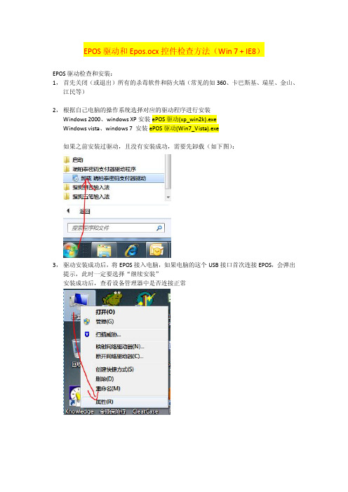
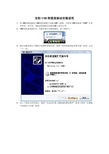
EPOS驱动和Epos.ocx控件检查方法(Win 7 + IE8)EPOS驱动检查和安装:1,首先关闭(或退出)所有的杀毒软件和防火墙(常见的如360、卡巴斯基、瑞星、金山、江民等)2,根据自己电脑的操作系统选择对应的驱动程序进行安装Windows 2000、windows XP安装ePOS驱动(xp_win2k).exeWindows vista、windows 7 安装ePOS驱动(Win7_Vista).exe如果之前安装过驱动,且没有安装成功,需要先卸载(如下图):3,驱动安装成功后,将EPOS接入电脑,如果电脑的这个USB接口首次连接EPOS,会弹出提示,此时一定要选择“继续安装”安装成功后,查看设备管理器中是否连接正常文字“Prolific USB-to-Serial Comm Port(COMx)”表示EPOS连接,其中COMx为通讯端口,因个人电脑而异,这里是COM8,如果看到这个则证明EPOS连接电脑是成功的。
Epos.ocx控件检查和安装:1,第一次进行EPOS刷卡,在弹出刷卡页面会提示安装Epos.ocx控件,选择“安装”,如果没有弹出安装提示,需要调整IE安全控制:2,安装Epos.ocx控件成功后,可以通过下面步骤检查是否安装成功:(1)通过IE的加载项查看(注意选择查看所有加载项)(2)去C:\Windows\Downloaded Program Files目录查看是否存在Epos.ocx文件,如果存在则表明安装成功(注意,不要手动copy这个文件到这个目录,必须使用IE弹出的提示进行安装)3,在EPOS驱动和Epos.ocx控件安装成功后可以进入行销的测试地址进行模拟刷卡,模拟刷卡没有问题了就可以保证设备、系统处于最佳状态,就可以放心去展业了。
测试地址:/life/testEpos.screen3,使用业务员用户、密码登陆即可测试。
Perle SX设备驱动软件和硬件安装快速入门指南说明书
IntroductionThis Quick Start Guide covers the key points of the installation of the SX device driver software and hardware. It is intended for systems administrators familiar with Windows NT, Windows 2000, SCO OpenServer 5, SCO UnixWare and Linux operating systems. To obtain the latest driver software please refer to the driver matrix page under technical support in Perle web site.Accessing the CDROMSolaris1.Login to your system as super user then load the CDROMinto your system CD drive.Solaris will automatically mount the CDROM when inserted, and start the file manager application.You can now browse the CDROM content using the File Management tools within Solaris.SCO OpenServer1.Login to your system as super user then load the CDROMinto your system CD drive.2.Mount the CDROM using themount-fISO9660-r/dev/cd0/cdrom command.You can now browse the CDROM content using the File Manager tool in the SCO OpenServer desktop.SCO UnixWare1.Login to your system as super user then load the CDROMinto your system CD drive.2.Mount the CDROM using themount-r-Fcdfs-o nmconv=c/dev/cdrom/cdrom1/mnt command.You can now browse the CDROM content using the File Manager tool in the SCO UnixWare desktop.Windows NTThe CDROM will be automatically mounted a short time after placing it in the CDROM drive. View with Windows Explorer. Windows 2000The CDROM will be automatically mounted a short time after placing it in the CDROM drive. View with Windows Explorer.Linux1.Login to your system as super user then load the CDROMinto your system CD drive.2.At the command prompt, type mount /mnt/cdrom.You can now browse the CDROM content using any one ofthe file browsers available for Linux.Installing driver softwareSolarisTo install under Solaris proceed as follows;1.Install any SX PCI host cards into your system.2.Login to your system as super user, begin a terminalsession then load the HandyWEB CDROM into yoursystem CD drive.3.At the command prompt, type:pkgadd-d/cdrom/handywebx/drivers/sxplus/solaris/sx-sol-<ver>.pkg and press the Enter key (where ver isversion number).4.At the resulting question prompt, select Y and press Enter.SCO OpenServerTo install under SCO OpenServer proceed as follows;1.Install any SX PCI host cards into your system.2.Login to your system as super user.3.Load the HandyWEB CDROM into your system CD drive.4.Mount the CDROM using themount-fISO9660-r/dev/cd0/cdrom command.5.In the SCO OpenServer desktop, double click on theSystem Administration folder.6.In the System Administration window, double click on theSoftware Manager icon.7.In the Software Manager menu, click onSoftware>Install New.8.In the Begin Installation window, click on the Fromlocalhostname button and then click on Continue.9.In the Select Media window, select the Media Imagesoption then click on Continue.10.In the Enter Image Directory window, type;/cdrom/drivers/sx/openserver and then click on OK11.In the Install Selection window, click on the Install button.12.If you are installing other drivers, turn off theRe-link Kernel option to prevent an unwanted kernel link.13.In the Specialix SX Configuration window now displayed,click on the Cards>Exit menu option to close thewindow.14.In the pop-up window that now appears (for successfulinstallation) click on OK to close the window.The software manager window is now updated to include theSX driver in the list of installed software.You can now installany ISA host cards and Device concentrators you require.SCO UnixWareTo install the SX device drivers and utilities for the SCOUnixWare operating system proceed as follows;1.Install any SX PCI host cards into your system.2.Login to your system as super user then load theHandyWEB CDROM into your system CD drive.3.Mount the CDROM using themount-r-Fcdfs-o nmconv=c/dev/cdrom/cdrom1/mntcommand.4.At the command prompt, type pkgadd -d/mnt/drivers/sx/unixware/sx.pkg slxos and press Enter.5.At the command prompt that now appears, typeshutdown-y-i6 and press Enter to shutdown and re-bootthe system.Upon completion of the system re-boot the SX drivers youhave installed are ready to use.You can now install any ISAhost cards and Device concentrators you require.LinuxTo install the SX device drivers and utilities for the Linuxoperating system proceed as follows;1.Install any ISA or PCI host card(s) and deviceconcentrator(s) onto your system.2.Mount the cdrom using the mount /mnt/cdrom command.3.Apply the kernel driver patch to kernel sources in/usr/src/linux: patch -p1</mnt/cdrom/drivers/sx/linux/sx.patch-1.30-2.2.144.Set the Kernel Configuration->CharacterDevices->Specialix SX (and SI) card support flag to m.e either the make config or make xconfig commands toapply this setting. Now rebuild and install the new kerneland modules then reboot using the new kernel.6.Install utilities RPM: rpm -i/mnt/cdrom/drivers/sx/linux/specialix_sxtools-4-1.i386.rpm.7.Load the SX driver: sxboot then load the host cardfirmware: sxmkdev -f.Your system is now ready to use the attached SX serial ports.Windows NTA device driver is installed with the PortDirector software,supplied on the CDROM. To install PortDirector:1.Load the CDROM then access the \drivers\portdirectordirectory, in Windows Explorer and double-click onSetup.exe.2.Follow the instructions on screen to install PortDirectorYou can now install any ISA host cards and Deviceconcentrators you require.Windows 2000To install under Windows 2000 proceed as follows;1.Install the SX cards you require and allow the operatingsystem to boot.2.Load the CDROM then in the popup window nowdisplayed, select the \drivers\sx\w2k directory and click onOK.You can now install PortDirector if required for managementof your serial ports. Alternatively, use the Windows2000Device Manager.The device drivers and software are now installedautomatically into the selected destination.You can now install any Device concentrators you require.Device concentrator pinoutsMX type device concentratorsAll MX type SX device concentrators are fitted with DB25male connectors as shown in the next table.DX type device concentratorsAll DX type SX device concentrators are fitted with DB25female connectors as shown in the next table.NoteAny installed SX cards will be automatically detected andassigned from PortDirector.Pin Signal Direction1Chassis2TXD Out3RXD In4RTS Out5CTS In6DSR In7GND8DCD In20DTR Out22RI InPin Signal Direction1Chassis2RXD In3TXD Out4RTS In5CTS Out6DSR Out7GND8DCD In20DTR In22RIInPin 1LookingintoconnectorRJX type device concentratorsAll RJX type SX device concentrators are fitted with RJ45 female connectors as shown in the next table.Installing host cardsPCI host cards1.Turn off the power to your system and remove the cover.2.Insert each card into a vacant PCI slot.3.Replace and secure the cover of your computer and restartyour machine. The SX card(s) should be detectedautomatically.ISA host card1.Set the address on each ISA host card using the address oneach ISA host card using the rotary switches SW1, SW2 and jumper J2 to the first three digits of the address you want as shown by the next example.2.Turn off the power to your system and disconnect themains supply.3.Remove the system cover to expose the inside of theconnector panel for host cards.4.Insert the ISA card you want to install into a vacant hostcard slot and secure in place.5.Repeat step 2. until you have installed all the ISA cardsyou want.6.Replace and secure the system cover.7.Plug in the mains lead and turn on the power.6.Power up your computer system.SXSerial connectivity systemQuick start guide•Up to 32 ports per card•Up to 4 cards per server Pin Signal Direction1DCD In2DTR Out3DSR In4S/GND5TXD Out6RXD In7RTS Out8CTS InShieldWarningDangerous voltages exist inside computer systems.Before installing host cards in your system, turn offthe power supply and disconnect the mains lead.CautionFull anti-static precautions should be taken when handlinghost cards.Pin 1(looking intoAddress SW1SW2J2J3C00000C No jumper NojumperC80000C Jumper fittedD00000D No jumperContacting Perle Technical SupportPerle offers free technical support to Perle AuthorisedDistributors and Registered Perle Resellers.To access technical support please visit the Perle websiteat /support.Here you will find:• latest drivers and firmware updates for download• technical tips• frequently asked questions• documentation。
Silicon Labs USB 驱动程序定制 - AN220说明书
AN220: USB Driver Customization Many of Silicon Labs' USB devices require device drivers to oper-ate within Windows. Default driver installers are provided for these devices. However, if the devices are customized with a non-default VID and/or PID, the drivers must also be customized. This application note provides a tool that creates custom driver installers for Windows to match a device's configuration. This tool also provides additional driver and installation options, such as silent install.The following drivers are available in this tool:• A Virtual COM Port Driver is available for the CP210x device family.• A WinUSB driver is available for the CP2130 device.•Direct Access Drivers(formerly called USBXpress) are available for the CP210x, C8051F32x, C8051F34x, C8051F38x, C8051T32x, C8051T62x, and EFM8UBx de-vice families.This document describes the steps necessary to customize the Windows device driver installation using the Custom USB Driver Installation Wizard.KEY POINT•Use the Custom USB Driver Installation Wizard to create a custom Windows driver installer with your unique VID/PID and installation options.APPLICABLE DEVICES•CP210x•CP2130•C8051F32x•C8051F34x•C8051F38x•C8051T32x•C8051T62x•EFM8UBxCustomizing Driver Installations 1. Customizing Driver InstallationsThe driver installation is customizable by modifying certain sections of the hardware installation files (.inf). The strings contained in the .inf files affect what is displayed in the “Found New Hardware Wizard” dialogs, Device Manager, and the Registry. The changes to the VID and PID in the driver installation should match the VID and PID contained in the EPROM/FLASH of your product. See “AN721: USBXpress™ Device Configuration and Programming Guide” for more information on changing the VID and PID for your product. Note: Any changes to the Windows installation .inf files will require new Windows Hardware Quality Labs (WHQL) tests.2. Using the Custom USB Driver Installation WizardThe Custom USB Driver Installation Wizard generates a custom driver installation for distribution to end-users. This customized installa-tion consists of modified .inf files, optional installation support files, and driver files for Windows 7/8/8.1/10.The optional installation executable provided can be used to copy driver files and register a device on a PC before or after the device has been connected. It will also add an entry in the add/remove programs listing. When the device is connected to the PC for the first time, the drivers will be installed with little interaction from the user.Note: A customized installation does not contain certified drivers for Windows 7/8/8.1/10. Certification must be performed by Microsoft for the new driver installation. Uncertified drivers cannot be installed in Windows 7/8/8.1/10 except under certain testing conditions.To run the Custom USB Driver Installation Wizard, open CustomUSBDriverWizard.exe, which is included in the AN220SW.zip down-load. The figure below shows the first screen of the Custom USB Driver Installation Wizard. Choose the type of driver installation de-sired. For detailed instructions on creating a custom driver installation, see 3. Creating a Custom Driver . This description goes through the process of customizing a CP210x driver. The process for creating a Direct Access (USBXpress) driver or CP2130 driver is the same as this description, only select “USBXpress WinUSB Driver Installation” or "CP2130 WinUSB Driver Installation" on the starting screenof the wizard, respectively.Figure 2.1. Driver Installation SelectionUsing the Custom USB Driver Installation Wizard3. Creating a Custom DriverThis section describes how to create a custom driver. To begin, choose the type of installation to customize: “Virtual COM Port Driver Installation”, “USBXpress WinUSB Installation”, or "CP2130 WinUSB Driver Installation". Differences between the three installations are noted, but a sample CP210x customization is shown in the figures. Next, determine if an installation executable should be generated (see 3.5 Installation String Options and 3.8 Generation Directory for more information on the generated installer), and click Next.3.1 Driver Certification WarningThe first screen is the warning explaining that the generated driver installation will not be certified. (See figure below.) Click Next to begin customizing your driver installation.Figure 3.1. Driver Certification Warning3.2 Operating System SelectionThe first step in the customization utility (shown in the figure below) is to specify the operating system for which the custom driver is being generated.Figure 3.2. Operating System Selection3.3 String and File Name CustomizationThe next step in the customization utility (shown in Figure 3.3 String and File Customization on page 6) is to specify your preferred strings and filenames. Each field is described in further detail below.3.3.1 Company Name (Long Name for .inf File Entries)The company name appears in the .inf file entries and has a maximum length of 255 characters.3.3.2 Company Abbreviation (Short Name for .inf File Entries)The abbreviation appears in the .inf file entries and has a maximum length of 31 characters.3.3.3 File Name for .infThis field allows for specification of a unique name for the .inf file. The maximum length of this string is eight characters. The generated file will be named xxxxxxxx.inf.Figure 3.3. String and File Customization3.4 VID, PID, and Device Name CustomizationThe next step in the customization utility (shown in Figure 3.4 VID and PID Customization on page 7) allows multiple VID/PID combi-nations in one driver. This entry is also where the Device Name, which appears in Windows Device Manager, is specified. An example for Windows 7 is shown in Figure 3.6 Windows 7 Device Manager Example on page 9.3.4.1 General Device Installation NameThis field is the general description of device installation. This will not appear in Device Manager, but will show up during installation if the user is prompted for a disk.The Device List allows multiple VID and PID combinations to be added to one driver. Current devices can be edited by double-clicking an entry.Figure 3.4. VID and PID CustomizationTo add a new entry, click the Add button. A new dialog box (shown in Figure 3.5 Add VID/PID/Device Name to Installation on page 8) will appear with the following options.3.4.3 Device TypeThis specifies which device is being customized. If the VCP driver for the CP2105 Dual UART Bridge is being customized, two interface names will appear. Likewise, if the VCP driver for the CP2108 Quad UART Bridge is being customized, four interface names will ap-pear. Otherwise, only one interface name will appear.3.4.4 VIDAllows specification of a new vendor ID (VID).3.4.5 PIDAllows specification of a new product ID (PID).This string will be displayed in Device Manager under the Ports or USB tab. If the VCP driver is being customized for a multiple-inter-face bridge device, one string will be displayed per interface.Figure 3.5. Add VID/PID/Device Name to InstallationFigure 3.6. Windows 7 Device Manager ExampleIf an installer is not being generated, then skip to 3.9 Option Verification.3.5 Installation String OptionsThe next step in the customization process is to specify options for the driver installer. The driver installer will allow for a device to be installed before or after a device has been connected to the PC. If this is run before a device is plugged in, drivers will already be regis-tered for devices that belong to that installation. If a device is already plugged in, the installer will rescan the bus for any devices for that installation. This section covers adding the installer's strings and is shown in Figure 3.7 Installation Strings on page 10. The driver installer and its corresponding setup.ini file are explained in further detail in “AN335: USB DRIVER INSTALLATION METHODS”.3.5.1 Product NameThis is the string that identifies the product installation in the Add/Remove Programs listing. The string shows up as “<Product Name String> (Driver Removal)” for easy identification.3.5.2 Name for Installation FileThis is will be the name of the installation executable and shows up as “<InstallName>.exe”.Figure 3.7. Installation Strings3.6 Device OptionsThe next step in the customization utility (shown in 3.6.2 Selective Suspend Support) is to configure the serial enumeration and selec-tive suspend options.3.6.1 Serial Enumeration SupportThis allows Windows to “enumerate” a device(s), such as serial mice or an external modem, connected to the CP210x . If your device always presents data to the PC (such as a GPS device), then disable this to prevent false serial enumerations.3.6.2 Selective Suspend SupportEnabling this feature will put the device to sleep if it has not been opened for a time longer than the specified Timeout Value. This is used to save power on the PC and is recommended unless your CP210x needs to be powered if a handle to the device is not opened.Figure 3.8. Device Options3.7 Installation OptionsSpecific options for the GUI should now be specified.3.7.1 Display GUI Window during InstallCheck this option when using the generated Installer as a stand-alone application. The Installer will display several GUI windows during the installation process. Uncheck this option to run the Installer in Quiet Mode. When running in Quiet Mode, no GUI will be displayed. This is useful when using another application to launch this Installer.3.7.2 Copy Files to Target Directory during Install:Check this option if a copy of the drivers will be needed on the hard drive. This is useful when installing the drivers from a CD. Uncheck this option if copies of the driver files are not needed on the hard drive.3.7.3 Target DirectorySelects the hard drive location that will contain a copy of the driver files. The default location is C:\Program Files\Silabs\MCU\CP210x for the VCP Driver and C:\ProgramFiles\Silabs\MCU\USBXpress for the USBXpress driver. If the “Display GUI window during Installa-tion” option is selected, this path can be changed during installation by clicking the Browse button. However, if the “Display GUI window during Installation” option is not selected, then the default directory is always used unless a directory is specified through the command line. This option is ignored if the “Copy Files to Directory during Setup” option is not selected.Note: The Target Directory must be different for each product released.3.7.4 Display GUI Window during UninstallCheck this option when using the generated Uninstaller as a stand-alone application. The Uninstaller will display several GUI windows during the uninstall process. Uncheck this option if the Uninstaller will be launched by another application. The Uninstaller then runs in Quiet Mode. When running in Quiet Mode, no GUI will be displayed.3.7.5 Remove Files from Target Directory during UninstallCheck this option if the files copied to the Target directory should be removed upon uninstallation. This option is ignored if the “Copy Files to Directory during Setup” option is not selected.Figure 3.9. Installation Options3.8 Generation DirectoryThe next step in the customization utility is to specify where this custom driver’s installation files will be generated. The default directory for a VCP driver is C:\Silabs\MCU\CustomCP210xDriverInstall, and the default for a USBXpress Driver is C:\Silabs\MCU\CustomUSBX-pressDriverInstall. However, a different directory can be selected or created. This step is shown in the figure below.Note: This is not an actual installation of the drivers. This is simply a directory to output all installation files needed for the installation. These files can be added to a CD or OEM installation for distribution to the end-user.Figure 3.10. Generation Directory3.9 Option VerificationThe final step in the customization utility is to review all of the selected options. If anything needs to be changed, the Back button can be used to go back to previous pages to change items. Once all options have been verified, press Finish to create the customized driver files. This step is shown in the figure below.Figure 3.11. Option VerificationCustomizing Driver Installations, macOS (Mac OS X) 4. Customizing Driver Installations, macOS (Mac OS X)If the VID or PID is changed from the default factory settings, contact Silicon Laboratories Support (https:///support) to obtain drivers that incorporate the new values. Mac OS X requires that the drivers be compiled with the values that will be used by the production CP210x device.Revision History 5. Revision HistoryRevision 1.1Jun, 2021•Updated the title of AN335.•Replaced the AN144 with the AN721.•Updated Figure 3.2.Revision 1.0August, 2018•Converted to new Appnote format.•Updated screenshots to match the current release of the customization tool.•Added references to CP2130 driver.•Updated Windows versions to currently supported versions 7/8/8.1/10.•Updated references to USBXpress drivers to mention the current name "Direct Access Drivers."•Added EFM8UBx devices to supported device list.Revision 0.7•Added CP2108 to Relevant Devices list.Revision 0.6•Added support for C8051F38x, C8051T32x, and C8051T62x devices.•Updated Figures 1 through 12.Revision 0.5•Added support for CP2104 and CP2105.•Added support for Windows 7.•Updated all screen shots of the AN220 software.•Updated explanations of AN220 software.Revision 0.4•Updated diagrams and wording to reflect 4.1 and later versions of the Custom Driver Wizard.•Updated to include documented support of C8051F34x devices.•Updated to reflect Vista support.Revision 0.3•Updated figures and customization description to reflect version 3.4 and later of the Custom Driver Wizard.•Removed USBXpress specific customization description. Version 3.4 and later contains the same process for customizing both VCP and USBXpress driver installations.•Removed preinstaller explanations and added descriptions on how the new Driver Installer is used.Revision 0.2•Added CP2103 to Relevant Devices on page 1.Revision 0.1•Initial revision.Silicon Laboratories Inc.400 West Cesar Chavez Austin, TX 78701USAIoT Portfolio/IoTSW/HW/simplicityQuality /qualitySupport & Community/communityDisclaimerSilicon Labs intends to provide customers with the latest, accurate, and in-depth documentation of all peripherals and modules available for system and software imple-menters using or intending to use the Silicon Labs products. Characterization data, available modules and peripherals, memory sizes and memory addresses refer to each specific device, and “Typical” parameters provided can and do vary in different applications. Application examples described herein are for illustrative purposes only. Silicon Labs reserves the right to make changes without further notice to the product information, specifications, and descriptions herein, and does not give warranties as to the accuracy or completeness of the included information. Without prior notification, Silicon Labs may update product firmware during the manufacturing process for security or reliability reasons. Such changes will not alter the specifications or the performance of the product. Silicon Labs shall have no liability for the consequences of use of the infor -mation supplied in this document. This document does not imply or expressly grant any license to design or fabricate any integrated circuits. The products are not designed or authorized to be used within any FDA Class III devices, applications for which FDA premarket approval is required or Life Support Systems without the specific written consent of Silicon Labs. A “Life Support System” is any product or system intended to support or sustain life and/or health, which, if it fails, can be reasonably expected to result in significant personal injury or death. Silicon Labs products are not designed or authorized for military applications. Silicon Labs products shall under no circumstances be used in weapons of mass destruction including (but not limited to) nuclear, biological or chemical weapons, or missiles capable of delivering such weapons. Silicon Labs disclaims all express and implied warranties and shall not be responsible or liable for any injuries or damages related to use of a Silicon Labs product in such unauthorized applications. Note: This content may contain offensive terminology that is now obsolete. Silicon Labs is replacing these terms with inclusive language wherever possible. For more information, visit /about-us/inclusive-lexicon-projectTrademark InformationSilicon Laboratories Inc.®, Silicon Laboratories ®, Silicon Labs ®, SiLabs ® and the Silicon Labs logo ®, Bluegiga ®, Bluegiga Logo ®, Clockbuilder ®, CMEMS ®, DSPLL ®, EFM ®, EFM32®, EFR, Ember ®, Energy Micro, Energy Micro logo and combinations thereof, “the world’s most energy friendly microcontrollers”, Ember ®, EZLink ®, EZRadio ®, EZRadioPRO ®, Gecko ®, Gecko OS, Gecko OS Studio, ISOmodem ®, Precision32®, ProSLIC ®, Simplicity Studio ®, SiPHY ®, Telegesis, the Telegesis Logo ®, USBXpress ® , Zentri, the Zentri logo and Zentri DMS, Z-Wave ®, and others are trademarks or registered trademarks of Silicon Labs. ARM, CORTEX, Cortex-M3 and THUMB are trademarks or registered trademarks of ARM Hold-ings. Keil is a registered trademark of ARM Limited. Wi-Fi is a registered trademark of the Wi-Fi Alliance. All other products or brand names mentioned herein are trademarks of their respective holders.。
usb驱动安装失败
USB驱动安装失败
简介
USB驱动在计算机中起到了连接外部设备和主机的关键作用。
当USB驱动安装失败时,可能导致无法正常使用USB设备。
本文将介绍一些常见的导致USB驱动安装失败的原因,并提供相关的解决方案。
常见原因
USB驱动安装失败可能有多种原因。
下面列举了一些常见的原因: 1. 不兼容的驱动版本:安装的驱动版本与操作系统版本不兼容。
2. 驱动程序损坏:驱动文件可能已损坏或不完整。
3. 旧的驱动程序未卸载:之前安装的旧驱动程序未正确卸载导致冲突。
4. USB接口故障:USB接口可能存在硬件故障导致驱动无法正确安装。
解决方案
针对上述常见原因,下面提供了一些解决方案:
1. 更新驱动程序
首先,应确保下载的驱动程序与当前操作系统版本兼容。
然后参考以下步骤更新驱动程序: 1. 打开设备管理器:在Windows操作系统下,可以通过在搜索栏中输入。
AnywhereUSB Gen 2 版本 3.99 Windows 驱动程序释放说明书

DIGI INTERNATIONAL9350 Excelsior Blvd, Suite 700Hopkins, MN 55343, USA+1 (952) 912-3444 | +1 (877) 912-3444AnywhereUSB Windows Driver Release NotesAnywhereUSB Gen 2Version 3.99 (December 04, 2019)INTRODUCTIONThis is a production release of the AnywhereUSB Generation 2 Windows Driver.SUPPORTED Products∙AnywhereUSB Gen 2 Windows Driver for 32-bit operating systems∙AnywhereUSB Gen 2 Windows Driver for 64-bit operating systemsSUPPORTED Operating Systems∙Windows 7∙Windows 8∙Windows 8.1∙Windows 10∙Server 2008-R2∙Server 2012∙Server 2012-R2∙Server 2016∙Server 2019KNOWN ISSUES∙The Belkin USB 2.0 4-port mobile-powered hub model F5U404BLK sometimes fails to enumerate when connected to AnywhereUSB.UPDATE BEST PRACTICESDigi recommends the following best practices:1.Uninstall the existing driver package via Add and Remove Hardware2.Install the new Windows driver package.TECHNICAL SUPPORTGet the help you need via our Technical Support team and online resources. Digi offers multiple support levels and professional services to meet your needs. All Digi customers have access to product documentation, firmware, drivers, and knowledge base and peer-to-peer support forums. Visit us at https:///support to find out more.CHANGE LOGVERSION 3.99 December 4, 2019NEW FEATURESNoneENHANCEMENTS1.AwUsbApi.dll is now multi-thread safe. This means that library functions can be calledconcurrently from different Windows threads.SECURITY FIXESNoneBUG FIXES1.With Windows 10 builds 1903 and 1908, the host computer would lose connectivity on reboot.This issue was determined to be due to the system network driver not being available at the time the AnywhereUSB system driver started. The “Digi AnywhereUSB Network Service” has been changed so that it works around this problem by disabling and re-enabling the “Network Attached USB Enumerator”. Note that this requires that the Startup Type of this service be configured for “Automatic” (which is the default).NOTE: The Microsoft-certified AnywhereUSB device drivers have not changed since v3.95 and will still show up with a version number of 3.95.2.AwUsbApi.dll AwUsbGetConnectionStatus function incorrectly reportedAWUSB_STATUS_IN_USE instead of AWUSB_STATUS_CONNECTED when the host itself was connected to an AnywhereUSB hub.VERSION 3.96 February 20191.The Windows Installer and the AnywhereUSB Configuration Utility are signed by DigiInternational to eliminate UAC (User Account Control) warning messages about unknown publisher.2.For customers using encrypted AnywhereUSB connections, the encryption service will nowuse certificates from either the Windows Local Machine Trusted Root CA store or theWindows Local Machine Intermediate CA store for authentication server certificates. In the previous 3.95 release, the encryption service only used the Trusted Root CA store.VERSION 3.95 April 20181.Several USB devices (e.g. Dediprog SF100 and Silicon Labs UART) fail to enumerate over ahigh latency WAN link. Fixed by setting ionhub service registry DWORD variableFastStartHub to 1. This variable is off (0) by default.[HKEY_LOCAL_MACHINE\SYSTEM\CurrentControlSet\services\ionhub]"FastStartHub"=dword:00000001(JIRA AWUSB-537)2.AnywhereUSB client driver awvusbd.sys blue-screens when connecting to an AnywhereUSBhub. Happens only with XenServer and XenCenter VM's. Fixed. (JIRA AWUSB-550)3.AnywhereUSB driver installer does not support upgrades. Installer now blocks attempts toupgrade over a previous installation. Previous installation must uninstalled first. You maybe prompted to reboot the computer. (JIRA AWUSB-438)ers can now import CA certificates to the Windows Certificate Store to authenticateserver certificates. The CA certificate must be installed on the "Local Computer" in theTrusted Root Certification Authorities store. (JIRA AWUSB-539)1.AwUsbGetConnectionStatus did not handle groups correctly. It also incorrectly reportedAWUSB_STATUS_IN_USE instead of AWUSB_STATUS_CONNECTED for host currentlyconnected to local machine. Fixed. JIRA AWUSB-492.2.On rare occasions the encryption service has stopped and forced users to restart it. It willnow automatically restart. (JIRA AWUSB-513)3.The encryption service now logs critical events which can be viewed from the WindowsEvent Viewer System log. (JIRA AWUSB-514)VERSION 3.91 September 20171.Client to hub connections with lengthy establishment times could lead to a blue screen ifprematurely disconnected by a user. Fixed. (JIRA AWUSB-421)2.Fixed memory leak in encryption service. (JIRA AWUSB-451)3.Disconnecting an AnywhereUSB hub connected to an Axis T8311 joystick caused a bluescreen. Fixed. (JIRA AWUSB-392)VERSION 3.90.223 June 20171.TLS v1.2 and SHA-2 (SHA-256) support. This only affects “Encrypted AnywhereUSB”.SHA-2 (SHA-256) certificates can now be used for authentication. Note that the certificatemust be signed using 2048-bit RSA encryption. Also, SHA-1 based certificates can still beused.Note:TLS v1.2 and SHA-2 support require AnywhereUSB firmware to be updated to at least rev N1(1.93). It still works with older firmware (starting with rev L v1.80) by "falling back" to TLS1.0.ers can specify a certificate "folder" instead of a certificate file when setting up"Encrypted AnywhereUSB" connections. You can specify it from the AnywhereUSBConfiguration Utility (AwUsbCfg.exe) or the console application (AwConsole.exe) just as you specify a file.Please note - to use a folder, each certificate must be renamed after the subject hash.Suppose you had a folder named c:\my-certs with two certificates - CertA.crt and CertB.crt.For example, to rename CertA.crt:a.Download an OpenSSL installer for Windows (version >= 1.0 since pre-1.0 versionsuse an older hash which will not work with AnywhereUSB).b.Open a command prompt from your certificate folder (c:\my-certs)c.Create a subject hash:c:\my-certs> openssl x509 -hash -in CertA.crt –nooutIt outputs an 8-digit hash (e.g. bc35a2e5)d.Rename (or copy) your certificate file with the hash as its base and the zerocharacter as its extension:c:\my-certs> copy CertA.crt bc35a2e5.0VERSION 3.90 January 20171.Support encryption in AnywhereUSB Programming API, AwUsbApi.dll.2.Workaround for Error Code 38. When all of the AnywhereUSB hubs are disconnected, thedevice manager unloads the ionhub.sys and awvusbd.sys drivers, and several outstanding references to the driver objects persist and block it from being removed from memory. Asubsequent attempt to connect to an AnywhereUSB hub will fail with an Error Code 38 and require a reboot in order to recover.To work-around this failure (most likely caused by intrusive third-party software) you must set these two variables to 1:[HKLM\System\CurrentControlSet\Services\AwVusbd]"DoNotUnload" = dword:1[HKLM\System\CurrentControlSet\Services\IonHub]"DoNotUnload" = dword:1Note: This work-around is disabled by default.VERSION 3.82 May 20161.Fix IOCTL Vulnerability - "Secunia advisory SA68000". (JIRA AWUSB-295)2.An unusually long network delay could lead to a BSOD. Fixed. (JIRA AWUSB-259)3.Fix Handle leak in Encryption Service. (JIRA AWUSB-310)VERSION 3.80 July 20151.Installer did not remove pre-InstallShield drivers (such as 3.60) and led to customercomplaints. Fixed.2.Configuration Utility was not remembering group assignment after disconnecting as it haddone in 3.60. Fixed.3.Added support in AwConsole for encrypted connections.VERSION 3.71 Jan 20151.OpenSSL encrypted USB traffic support (AES-128 encryption only). Firmware version 1.81and later is required.2.Optional "tunneling" of TCP connections over a single TCP connection between the hostand the AnywhereUSB remote hub to eliminate network disconnects due to inactivity. Note that tunneling is enabled automatically when data encryption is turned on. Firmwareversion 1.80 and later is required.3.New installer. Uninstalls will be done conventionally from Programs and Features insteadof from the Configuration Utility. However the configuration utility must be used touninstall an older version if you are upgrading. Note that the new installer copies the driver files to C:\Program Files\Digi\AnywhereUSB by default instead of c:\AnywhereUSB.4.The hub driver would sometimes unload with pending network I/O resulting in a bluescreen. Fixed.5.This release no longer supports signed drivers for Windows XP, Server 2003, and Server2008.VERSION 3.60 May 20141.Low and Full Speed devices which are attached to AnywhereUSB via an external USB2.0hub did not enumerate. Fixed. (JIRA AWUSB-77)2.AwUsbView did not show device speeds correctly. Fixed. (JIRA AWUSB-54)3.Add Multi-Host support to AwUsbApi DLL. (JIRA AWUSB-65)4.If a USB string contained zero as a character, AnywhereUSB would incorrectly treat it as aninvalid string. Fixed.5.Removed Reboot and Configure commands from AwConsole (the console configurationapp). (JIRA AWUSB-80)6.Added work-around for Microsoft Windows 8 / Server 2012 bug which kept USB MassStorages devices from working. (JIRA AWUSB-77)7.Fix bug with MultiTT (Multi Transaction Translator) external hub. (JIRA AWUSB-87)8.UnInstaller failed on Windows 8 because of a deprecated registry key. Fixed. (JIRA AWUSB-88)9.UnInstaller failed to bring up log in Windows 8 and Server 2012. Fixed. (JIRA AWUSB-88)10.When certain devices are removed, awvusbd.sys was causing a BSOD. Fixed. (JIRA AWUSB-86)11.Removed firmware and configuration app for legacy AnywhereUSB/5 devices. They will nolonger be supported going forward.VERSION 3.51 January 20131.Fix critical memory leak in awusbsys driver.2.If you put awusbsys and awvusbd under Driver Verifier, it would cause a blue-screenbecause of the DV filter. Fixed.3.The “X” icon at the top-right now closes the AWUSB Configuration Utility. It used tominimize it to the System Tray.4.The Connection List now has Group Number field. This was added to support connectivityto MHC (Multi-Host Connections) capable AnywhereUSB hubs that couldn’t be discovered.5.Event Logging section has been removed from File / Preferences window. Digi tech supportwill provide specific logging methods for troubleshooting if needed.6.Event Log button, which was only for the legacy AnywhereUSB/5, has been removed. Digitech support will provide specific logging methods for troubleshooting if needed.7.The AnywhereUSB Configuration Utility executable and the three AnywhereUSB drivers (.sysfiles) all share the same version numbers now.8.The Configure button is now only used to configure Group Numbers for 2nd generationmodels which are running v1.38 (or newer) firmware. Network configuration and FriendlyName changes are no longer supported with the Configure button. Use the DeviceDiscovery Utility or the AnywhereUSB Web UI to make network configuration changes. Use the AnywhereUSB Web UI to make Friendly Name changes.VERSION 3.50 October 20121.In rare circumstances, the endpoint receiver handler locks up when it receives a partialmessage from TDI. Rebooting the host was the only way to recover from this in a MultiHost environment. Fixed.2.Added a MultiString registry variable, "SkipMsOsDescrDevList", which can be used to defineproblematic USB devices which fail enumeration if they receive a Get String Descriptorrequest for the Microsoft OS Device Descriptor.3.AwUsbCfg.exe - Add Group Number field to Connection List Dialog. This only affects userswho have to connect to a hub on a different subnet.VERSION 3.30 February 20121.Updated driver to use Microsoft's new value of USBD_STATUS_CANCELED. Using the oldvalue caused some devices to hang.2.Initialize the wValue field of the setup packet. This fixed support for Aladin EToken.3. A device with a very long USB serial number string could cause a blue screen. Fixed.4.IonHub ignored IOCTL_INTERNAL_USB_CYCLE_PORT. Fixed. Some USB functional driversdepend on this IOCTL.5.If a functional driver used the WdfDeviceAssignS0IdleSettings/IdleUsbSelectiveSuspendmethod for its device, it failed because IonHub reported that the device could wake fromPowerDeviceD3. It (ionhub.sys) has been fixed by reporting PowerDeviceD2 in DeviceWake.This fixes a problem seen with Texas Instruments umpusbvista.sys functional driver for its 3410 USB to serial converter.6. A column in Configuration Utility that was used to display the address of the host in theHost to group assignments was too narrow for an IP address of 12 digits. This caused aline wrap in the Host Column and all subsequent group assignments were displayed off by one.。
NEC USB 2.0 USER MANUAL
NEC USB 2.0Version 1.0Contents1.0 USB Port Features ………………………………….P.32.0 System Requirement………………………………….P.33.0 Driver Limitations……………………………………..P.34.0 Driver Installation (W indows XP)……………………….P.45.0 Driver Installation (Windows 2000)………………….P.106.0 Driver Installation (Windows ME)……………………P.167.0 Driver Installation (Windows 98/98SE)………………P.192IntroductionAdd a USB device to your PCInstantly add USB peripherals to your PC. Never open your computer case again after you have your USB Port (PCI) card installed and say good-bye to confusing cables.The USB Port (Universal Serial Bus) allows you to instantly connect USB devices to your computer. The USB Port will allow you to attach 3/4/5 USB devices instantly.You never have to worry about running out of slots in your computer or those confusing IRQ’s again. You can also “Hot Swap” your USB devices. What does this mean? You never have to power down your PC to install hardware again. Gamers can switch joysticks on the fly. Welcometo the USB Revolution.1.0 USB Port FeaturesThe PCI is a true 32-bit PCI-Bus USB card. It supports the following I/O features:3/4/5 USB ports (root hub and two/three/four down stream function ports)Auto detect speeds and connections of devicesIntegrated physical layer transceiversNormal and low power operating modesFully Plug and Play compatibleOHCI (Open Host Controller Interface) specification V1.0 register compatibleUSB specification V.1.0 compatible2.0 System RequirementsThis setup program will install the driver for NEC USB 2.0 Host Controller. Before you start to run the setup program, please make sure your computer is an IBM PC-compatible system.This driv er can be used either the following operating systems:Windows98Windows98 Second Edition.Windows Millennium.Windows 2000.Windows XP.3.0 Driver LimitationsCurrent limitations of the driver are: Composite devices and Hi-Speed Isochronous Transfers are currently not supported.34. Driver Installation (Windows XP)1. Please make sure this PCI card has been installed on your system correctly.When starting Windows XP, it will display the follow screen, please select “Install from a list or specific location [Advanced]”.42. Insert the “Driver CD” into the CD-ROM and select the “Include this location in the search”.Please use the Browse to change the path to “your cdrom driver:\USB\Item\98 me 2k xp”.53. When display Hardware Installation screen, Press “Continue Anyway”.4. Wait a moment to install files into your system. Then press “Finish”.65. To check your device from “Device Manager”. Press “Start¡÷My Computer¡÷Properties”.76. Open “Device Manager” and check if your device works.87. Note! If there is a yellow exclamation mark on “NEC PCI to USB Enhanced Host Controller”or “USB 2.0 Root Hub Device”, please remove this item from the “Device Manager” byclicking the “Uninstall” button and click “Refresh” to re-install this driver again.95.0 Driver Installation (Windows 2000)1. Please make sure this PCI card has been installed on your system correctly.When starting Windows 2000, the system will find “Universal Serial Bus (USB) Controller”.2. Press “Next”.103. Select “Search for a suitable driver for my device [recommended]” and press “Next”.4. Select “Specify a location” and press “Next”.115. Insert the “Driver CD” into the CD-ROM and use the Browse to change the path to “yourcdrom driver:\USB\Item\98 me 2k xp”.6. Choose the “ousb2.inf” file and press “Open”..127. Press “Next”.8. Press “Finish”.139. To check your device from “Device Manager”. Press “Start¡÷My Computer¡÷Properties”. Open “Device Manager” and check if your device works.1410. Note! If there is a yellow exclamation mark on “NEC PCI to USB Enhanced Host Controller”or “USB 2.0 Root Hub Device”, please remove this item from the “Device Manager” byclicking the “Uninstall” button and click “Refresh” to re-install this driver again.156. Driver Installation (Windows ME)1. Please make sure this PCI card has been installed on your system correctly.When starting Windows ME, it will display the follow screen, please select “Specify the location of the driver [Advanced]”.2. Select “Specify a location”. Insert the “Driver CD” into the CD-ROM and use the Browse tochange the path to “your cdrom driver:\USB\Item\98 me 2k xp”. Press “Next”.163. Press “Next”4. Press “Finish”.Note! This will restart your system. Please remember to close other programs before you click “Finish” button.175. After restarting your system, please check if your device works.Note:Note! If there is a yellow exclamation mark on “NEC PCI to USB Enhanced HostController [E13+]” or “USB 2.0 Root Hub Device”, please remove this item from the“Device Manager” by clicking the “Uninstall” button and click “Refresh” to re-install thisdriver again.187.0 Driver Installation (Windows 98/98SE)1. Please make sure this PCI card has been installed on your system correctly. When starting Windows 98/98SE, the system will find the new hardware. Press “Next”.2. Select “Search for the best driver for your device [Recommended] and press “Next”.193. Select “Specify a location”. Insert the “Driver CD” into the CD-ROM and use the Browse tochange the path to “your cdrom driver:\USB\Item\98 me 2k xp”. Press “Next”.4. Press “Next”.205. Press “Next”.6. The system will ask you where is the Windows 98/SE CD-ROM ? Please insert the Windows 98/SE CD and use “Browse” item to change the path.217. Press “Finish” and system will find the new hardware again. Please repeat Step 1 to Step 6.8. When display the follow screen, press “Next”.229. Press “Next” then finished the driver install steps.10. After restarting your system, please check if your device works.Note! If there is a yellow exclamation mark on “NEC PCI to USB 2.0 Enhanced Host Controller” or “USB 2.0 Root Hub Device”, please remove this item from the “Device Manager” by clicking the “Uninstall” button and click “Refresh” to re-install this driver again.23。
Android2.2_usb驱动安装说明

1.机器开启后,连接usb线,桌面会弹出找到新的硬件向导。
点击取消,手动安装。
2.打开设备管理器,如下图所示,我们可以找到新的Qualcomm HSUSB设备。
3.双击Qualcomm HSUSB设备,(或者右键点击Qualcomm HSUSB设备,选择属性),4.选择详细信息,得到设备ID:VID_050C&PID_9025&MI_01.5.选择驱动程序选项卡,点击“更新驱动程序”,选择“从列表或指定位置安装(高级)”6.单击下一步,选择“不要搜索。
我要自己选择要安装的驱动程序”7.单击下一步,选择“从磁盘安装”8.点击浏览,选择USB_ANDROID2.2 所在的文件夹。
这里要用到我们前面获取的设备ID. VID_050C&PID_9025&MI_00: DIAG驱动,位于USB_ANDROID2.2\ usb_func2.2\qcser.inf VID_050C&PID_9025&MI_01: MODEM驱动,位于USB_ANDROID2.2\ usb_func2.2\qcmdm.inf VID_050C&PID_9025&MI_02: GPS驱动,位于USB_ANDROID2.2\ usb_func2.2\ qcser.infVID_050C&PID_9025&MI_04: ADB驱动,位于USB_ANDROID2.2\ adb\ android_usb.inf根据相应的设备id,选择相应的inf文件。
9.点击确定,选择下一步:10.此时弹出硬件安装对话框,点击仍然继续。
11.11.点击完成,该设备安装完成。
12.重复以上步骤,逐步安装各个设备驱动。
Testo USB驱动安装说明书

Application informationTesto USB driverWindows ® 7, Windows ® 8.1, Windows ®10General informationPlease take the time to read the Installation Instructions through carefully and makesure you become familiar with how the device operates before using it. Always keep this document close to hand for reference purposes.SymbolsFont style- Terms which you will find on the screen are written in italics.- Terms which you will find on the screen and which you can “click on” are written in bold.TrademarksMicrosoft ® and Windows® are registered trademarks of the Microsoft Corporation in the USA and/or other countries.Intel ® and Pentium ® are trademarks of the Intel Corporation in the USA and/or other countries.Other trademarks or product names are the property of the respective companies.Operating SystemsThe images are taken from a Windows 7 System. For a detailed description, see the user manual for your Windows operating system.23ContentsGeneral information (2)Contents (3)1. Licence agreement (4)2. Installation (5)3. Virtual COM port settings (6)4. Troubleshooting (7)1. Licence AgreementThis is a legally valid contract between you, the end user, and Testo. When you or a person authorised by you opens the sealed CD-ROM package, you recognise the provisions of this contract. If you do not agree with the terms and conditions, you must immediately return the unopened software package with the accompanying items, including all written documents and other containers, to the place from which you bought the software, which will give you a full refund of the purchase price.Granting of a licenceThis licence entitles you to use a copy of the Testo software which was acquired with this licence on a single computer subject to the condition that the software is only ever used on one single computer at any one time. If you have bought multiple licences for the software, you may only have as many copies in use as you have licen-ces. The software is “in use” on a computer if it is loaded in the intermediate memory or RAM or stored on a per-manent memory, e.g. a hard disk, of this computer, with the exception that a copy which is installed on a network server for the sole purpose of distribution to other computers is not “in use”. If the foreseeable number of users of the software exceeds the number of licences acquired, you must ensure, through the necessary mechanisms or procedures, that the number of persons using the software at the same time does not exceed the number of licences.CopyrightThe software is protected against copying by copyright laws, international agreements and other legal provisions.You may not copy the software, the handbooks for the product or any other written documents accompanying the software. The software may not be licensed, let or leased to third parties. If the software is not fitted with a dongle, you may either make a single copy of the software solely for backup or archiving purposes or transfer the software to a single hard disk, provided that you keep the original solely for backup or archiving purposes. You are not permitted to reverse engineer, decompile or disassemble the software. Testo SE & Co. KGaA, Lenzkirch, may take legal action against you for any breach of property rights by you or by any person acting, directly or indirectly, under your authority.Limited guaranteeTesto guarantees for a period of 90 days from purchase of the software by the buyer, or for a longer minimum period if such a period is prescribed by the laws of the country in which the product is sold, that the software conforms to general standards defined in the accompanying documentation. Testo expressly does not guarantee that the software will operate without interruption or without errors. Should the software not function according to the accompanying documentation when in normal use, the buyer will have the right to return the software to Testo within the warranty period and to inform Testo in writing of the deficient functional capacity. Testo will only be bound to make a functional copy of the software available to the buyer within a reasonable period of time from receipt of the notification of functional incapacity or, should a copy not be available for any reason, to reimburse the buyer for the purchase price.Any warranty in respect of the software, the associated manuals and written material extending above and bey-ond the limited guarantee outlined above is excluded.Neither Testo nor the suppliers of Testo are liable to pay compensation for any losses arising as a result of use of this Testo product or the inability to use this Testo product, even if Testo has been informed of the possibility ofsuch a loss. This exclusion does not apply for losses occasioned through intent or gross negligence on the part ofTesto. Claims founded on mandatory statutory provisions regarding product liability are likewise unaffected.Copyright © 2018 by Testo SE & Co. KGaA5Administrator rights are necessary for installation.3 USB interface/adapter is not connected to thecomputer.1 Insert CD-ROM.If the installation program does not start automatically:> Open My Computer, select the CD drive, doubleclick on TestoSetup.exe.- The question Do you want to allow the followingprogram to install Software on this computer? isdisplayed.2 Confirm with Yes.- The assistent for the testo USB Driver setupappears.3 Continue with Next.- The status Installing testo USB Driver is displayed.- The text Completed the testo USB driver SetupWizard is displayed.4 End installation with Finish.2. Installation6The following description applies only to testo 174(0563 1741), testo 175 (0563 1754-1761), testo 177(0563 1771-1775), testo 580 (0554 1778)3 USB interface/adapter is connected to the comput-er, USB-driver and, if necessary, adapter-driver areinstalled.For Windows 7®:1 Select Start > Control Panel > System and Security >System > Device Manager.For Windows 8.1®:1 Select Start (right mouse buttom) > Device Manager.For Windows 10®:1 Select Start (right mouse buttom) > Device Manager.2 Click on Ports (COM & LPT).- The entries for this category are displayed.3 Search for entries with …Testo ...“ ,followed by a COMinterface number.You require this COM interface number when youconnect the data logger to the Comsoft software.The COM interface number only remains the same ifyou always connect the USB interface to the sameUSB port, or if it is left connected.3. Virtual COM port settings7 4. TroubleshootingError report:In the instrument manager appears.Cause:Driver installation was not carried out correctly.Error correction:Re-install driver.In Windows 7®:Context menu Properties > Driver > Update Driver... > OK.In Windows 8.1®Context menu Properties > Driver > automaticallyIn Windows 10®Context menu Properties > Driver > automatically.If malfunctions occur which you cannot solve yourself, please contact your dealer or Testo customer service. For contact data see the rear of this document or www.testo. comTesto SE & Co. KGaATesto-Straße 179853 LenzkirchGermanyTel.: +49 7653 681-0Fax: +49 7653 681-7699E-Mail:*************www.testo.de0973 0441 en 05。
Tripp Lite USB 2.0 文件传输适配器说明书
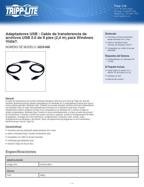
EspecificacionesAdaptadores USB - Cable de transferencia de archivos USB 2.0 de 8 pies (2,4 m) para Windows Vista?.NÚMERO DE MODELO: U233-008GeneralEl cable de transferencia de archivos USB para Windows Vista de 2.44 m [8 ft] de Tripp Lite, permitetransferir fácilmente archivos desde computadoras con Windows XP a computadoras nuevas que usan el nuevo sistema operativo Windows Vista. También se usa para transferir archivos entre dos computadoras con Windows Vista. El cable está diseñado para funcionar con el Asistente Vista Easy Transfer.Simplemente instale el software incluido en su computadora con Windows XP y conecte el cable enambas computadoras. Windows Easy Transfer se activa automáticamente y lo guía a través del proceso de transferencia. Transfiera: cuentas de usuario, archivos y carpetas, archivos y configuraciones de datos de programa, mensajes de correo electrónico, configuraciones, contactos, fotos, música, video,configuraciones de Windows y de internet. (Nota: las aplicaciones de programas no son transferibles)Garantía de por vida de Tripp Lite.CaracterísticasTransfiera archivos fácilmente desde Windows XP a Vista q Utiliza el Asistente Easy Transfer de Windows Vista q Compatible con USB 2.0 de alta velocidad q Certificado para Windows Vista q Garantía Tripp Lite de por vida.qDestacadoTransfiera archivos fácilmente desde Windows XP a Vista qUtiliza el Asistente EasyTransfer de Windows Vista™qCompatible con USB 2.0 de alta velocidadqRequisitos del SistemaComputadoras con Windows XP o Vista.qEl Paquete IncluyeCable USB 2.0 macho "A" a macho "A" de 8 pies (2,4 m).qSoftware en CD.q Manual del usuario.q© 2022 Tripp Lite. Todos los Derechos Reservados.。
三代USB驱动程序安装(Ⅲ version usb drive install)(1)
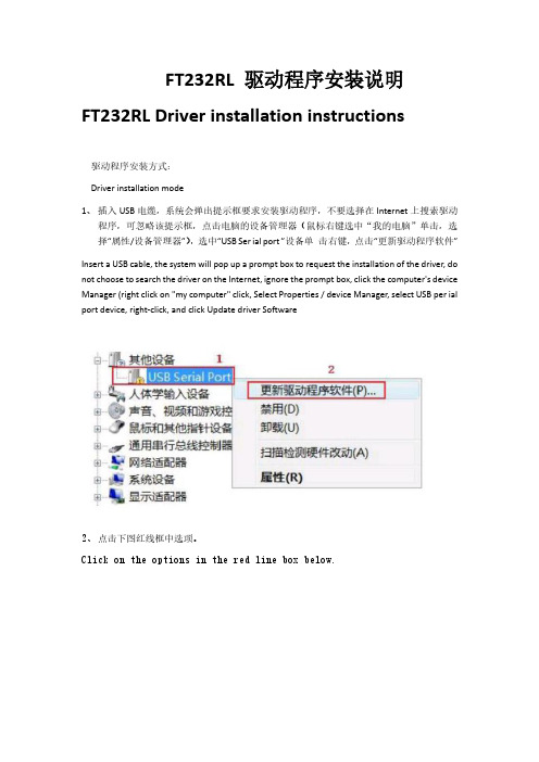
FT232RL 驱动程序安装说明FT232RL Driver installation instructions驱动程序安装方式:Driver installation mode1、插入USB电缆,系统会弹出提示框要求安装驱动程序,不要选择在Internet上搜索驱动程序,可忽略该提示框,点击电脑的设备管理器(鼠标右键选中“我的电脑”单击,选择“属性/设备管理器”),选中“USB Ser ial port ”设备单击右键,点击“更新驱动程序软件”Insert a USB cable, the system will pop up a prompt box to request the installation of the driver, do not choose to search the driver on the Internet, ignore the prompt box, click the computer's device Manager (right click on "my computer" click, Select Properties / device Manager, select USB per ial port device, right-click, and click Update driver Software2、点击下图红线框中选项。
Click on the options in the red line box below.3、点击“浏览”按钮,选择你的驱动程序所在的文件夹,如下图Click the Browse button and select the folder where your driver is located, as shown in the following figure4、安装完驱动程序后,在Windows 的设备管理器” 菜单的“端口(COM 和LPT)”下面出现一个新的串口,如下图红框中的 COM3,这个COM3就是编程电缆使用的COM 口。
LaserCAD操作说明

LaserCAD 软件操作说明书
3.5.5 矩形 ................................................................... 17 3.5.6 椭圆 ................................................................... 17 3.5.7 贝塞尔曲线 ............................................................. 17 3.5.8 文本 ................................................................... 18 3.6 工具 ....................................................................... 18 3.6.1 阵列复制 ............................................................... 18 3.6.2 按图层选择对象 ......................................................... 18 3.6.3 水平翻转 ............................................................... 19 3.6.4 垂直翻转 ............................................................... 19 3.6.5 手动排序 ............................................................... 19 3.6.6 优化排序 ............................................................... 20 3.6.7 曲线光滑 ............................................................... 20 3.6.8 删除重叠线 ............................................................. 20 3.6.9 合并相连线 ............................................................. 21 3.6.10 编辑引入引出线 ........................................................ 21 3.6.11 自动生成引入引出线 .................................................... 21 3.6.12 位图反色 .............................................................. 22 3.6.13 位图挂网 .............................................................. 22 3.6.14 创建位图块 ............................................................ 23 3.6.15 创建位图轮廓线 ........................................................ 24 3.6.16 闭合检查 .............................................................. 24 3.6.17 平行偏移 .............................................................. 24 3.6.18 测量周长 .............................................................. 25 3.6.19 预算加工时间 .......................................................... 25 3.6.20 模拟加工输出 .......................................................... 25 3.7 设置 ....................................................................... 25 3.7.1 系统参数设置 ........................................................... 25 3.7.1.1 工作空间 ............................................................. 26 3.7.1.2 附加功能 ............................................................. 27 3.7.1.3 工艺参数 ............................................................. 29 3.7.1.4 厂家参数 ............................................................. 30 3.7.1.5 用户参数 ............................................................. 33 3.7.2 阵列加工参数 ........................................................... 35 3.7.3 图形相对位置 ........................................................... 35 3.7.4 恢复到默认参数 ......................................................... 36 3.8 视图 ....................................................................... 37 3.8.1 如何调出隐藏的工具栏 ................................................... 37 3.9 帮助 ....................................................................... 37 3.9.1 关于信息的修改与定制 ................................................... 37 3.9.2 软件图标的修改 ......................................................... 39 4.1 通过 USB 与板卡建立连接 ..................................................... 39 4.2 选择网络通信方式 ........................................................... 40 4.2.1 通过网络与板卡直连 ..................................................... 40 4.2.2 通过路由器与板卡连接 ................................................... 43 4.3 设置图层参数 ............................................................... 45 4.3.1 调整图层的加工顺序 ..................................................... 49 4.4 设备控制 ................................................................... 49 4.5 加载图形数据以及设备文档管理 ............................................... 49 4.5.1 启动加工以及相关控制 ................................................... 52 5.1 手动加载“AWCLASERCUT”工具条 ............................................... 53 5.2 显示被隐藏的“AWCLASERCUT”工具条 ........................................... 55 5.3 导入 DST/DSB 文件 ........................................................... 55 5.4 从 CORELDRAW 切换到通用版软件 ................................................ 56 6.1 手动加载“激光加工”菜单和“激光加工”工具条 ............................... 57 6.2 从 AUTOCAD 切换到通用版软件 ........................................AD 软件操作说明书
USB2.0到以太网适配器快速安装指南说明书
USB2.0 to Ethernet adapterQ u i c k I n s t a l l a t i o n G u i d eVersion 1.0 July, 2006M u l t i-L a n g u a g e s Q I G i n D r i v e r C D =============================Če s ký:Anglického průvodce rychlou instalací naleznete na přiloženém CD s ovladačiD e u t s c h:Finden Sie bitte das englische QIG beiliegend in der Treiber CD (German)E s p año l:Incluido en el CD el QIG en Ingles.F r a nça i s:Veuillez trouver l’anglais QIG ci-joint dans le CD driverI t a l i a n o:Incluso nel CD il QIG in Inglese.M a g y a r:Az angol telepítési útmutató megtalálható a mellékelt CD-nN e d e r l a n d s: De engelstalige QIG treft u aan op de bijgesloten CDP o l s k i: Skrócona instrukcja instalacji w języku angielskim znajduje się na załączonej płycie CDP o r t u g uês: Incluído no CD o QIG em inglês.Русский:Найдите QIG наанлийскомязыкенаприложеном CDTür kçe:Ürün ile beraber gelen CD içinde Türkçe HızlıKurulum Kılavuzu'nu bulabilirsinizIntroductionThank you for purchasing the USB2.0 10/100Mbps to Fast Ethernet Adapter. This unique cable adapter allows you to connect your computer into Internet in the fast and easy way.SpecificationsStandardsz IEEE 802.3 10Base-T and 802.3u 100Base-TX Compliantz USB specification 1.0 /1.1 and 2.0 compliantConnection Modez Full or Half duplex for both 10Mbps and 100MbpsMedia Supportedz Category-3, 4, 5 for 10Base-T and Category 5 for 100Base-TX LEDsz Link/Active LED indicatorFeaturez USB specification revision 1.0/1.1 and 2.0 full speed compliantz Complies with IEEE 802.3 10Based-T and 802.3u 100Base-TXz USB interface to desktop/notebook PC without power adapterz RJ-45 connector to 10Mbps or 100Mbps Ethernet networks10/100Mbps Auto-Sensez Full/Half Duplex auto-negotiation for both 10Base-T and 100Base-TX z Compatible with Windows 98SE / ME / 2000 / XPDevice Installation GuideFollow the steps below on installing the USB2.0 10/100 Fast Ethernet adapter cable:Step1.Please connect the male B-connector of 1.5M USB2.0 cable to the female USB B-connector of USB2.0 Fast Ethernet Adapter and RJ-45 connector of networking cable to another end of USB2.0 Fast Ethernet Adapter. Step2.Connect the male A-connector of 1.5M USB2.0 cable to an available USB2.0 port on the computer or an available USB2.0 port on the USB2.0 HUB plugged into the computer.D r i v e r i n s t a l l a t i o n f o r W i n d o w s98S E/M eStep1. Power on the computer. “New Hard Ware Found” window comes up to request you to insert the driver diskette, and click “OK”.Step2. Select “Search the proper files of driver”, and click “Next”.Step3. Insert the driver disc into the computer. Select “CD-ROM Devices” or “specify a Location” link D:\Driver\EU-4206, and click “Next”.Step4. The driver will be found, and click “Next” to proceed.Step5. The system will ask windows 98SE original disk.Step6. Please insert the disk, and the system will install driver automatically.Step7. Click “Finished” completing installation.Step8. Windows 98SE / Me will find the driver and automatically configure the USB Fast Ethernet Adapter.Step9. Reboot the computer and remove the driver disc. The driver will take effect.Step10. Check if the device is complete install in your computer“ My Computer →(right key on the mouse) content → Hardware →Device Manager.D r i v e r i n s t a l l a t i o n f o r W i n d o w s2000Step1. Power on the computer. When the “New Hardware Found Wizard” window comes up, click “Next” to install the driver.Step2. Select “Search the proper files of driver”, and click “Next”.Step3. Insert the driver disc into the computer. Select “CD-ROM Devices” or “specify a Location” link D:\Driver/EU-4206, and click “Next”.Step4. The driver will be found, and click “Next” to proceed.Step5. Click “Finished” to complete installation.Step6. Windows 2000 will automatically configure the USB Fast Ethernet Adapter.Step7. Reboot the computer and remove the driver disc. The driver will take effect.Step8. Check if the device is complete install in your computer “ My Computer →(right key on the mouse) content → Hardware →Device Manager.D r i v e r I n s t a l l a t i o n f o r W i n d o w s X PStep1. Power on the computer. When the “New Hardware Found Wizard” windows comes up, select “install from a list or a specific location (Advanced)”, and click “Next”.Step2. Insert the driver disc into the computer. Select “CD-ROM Devices” or “specify a Location” link D:\Driver/EU-4206, and click “Next”.Step3. Windows XP will find the driver and request to continue installing and copying needed files”.Step4. Click “Finished” to complete the installation.Step5. A dialogue box will appear above the taskbar showing “New network device installed”.Step6. Reboot the computer and remove the driver disc. The driver will take effect.Step7. Check if the device is complete install in your computer“ Star →My Computer →(right key on the mouse) content → Hardware →Device Manager。
JetFlash USB2.0 中文说明书

JetFlash™ 中文使用手冊(版本 1.1)目錄產品介紹 (2)包裝內容 (2)產品特色 (2)系統需求 (2)安裝驅動程式 (3)在Windows® 98SE(第二版)下安裝驅動程式 (3)在Windows® Me、2000 及XP 下安裝驅動程式 (3)在Mac® OS 9.0或之後的版本下安裝驅動程式 (3)在Linux® Kernel 2.4.2或之後的版本下安裝驅動程式 (3)將JetFlash™ 格式化 (4)如何安全地移除JetFlash™ (5)在Windows® 98SE (第二版)下移除JetFlash (5)在Windows® Me、2000及XP下移除JetFlash (5)在Mac® OS 9.0, 或更新的版本; 及Linux® Kernel 2.4.2, 或更新的版本下移除JetFlash (5)JetFlash™ 150 系列產品 (6)產品規格 (6)訂購資訊 (6)JetFlash™ 120系列產品 (7)產品規格 (7)訂購資訊 (7)JetFlash™ 110系列產品 (8)產品規格 (8)訂購資訊 (8)JetFlash™ 2A系列產品 (9)產品規格 (9)訂購資訊 (9)產品介紹感謝您選購創見資訊所生產製造的JetFlash™ 。
本產品能讓您更方便且快速地在個人電腦與筆記型電腦間,存取及傳輸大量資料。
由於本產品提供較傳統儲存裝置更高的容量、及更快的傳輸速率,其功能可用來儲存/備份/傳輸您的檔案、資料夾、文件、照片及其它的電子檔。
此外它的超強可攜性及資料保存能力,搭配令人驚豔的流線外觀,絕對會帶給您截然不同的全新感受。
包裝內容JetFlash™系列產品之包裝盒內含有下列物品:JetFlash™頸繩應用軟體光碟USB延長線(只有JetFlash™ 2A 系列提供)快速安裝說明產品特色符合USB2.0 介面規格並相容於 USB1.1規格。
新EPOS驱动程序安装手册
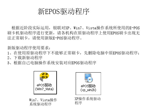
根据近阶段实际运用,银联对XP、Win7、Vista操作系统所使用的E-POS 刷卡机驱动程序进行更新,请各机构在原驱动程序上使用EPOS刷卡出现无 法正常刷卡,请使用新版E-POS驱动程序。 新版驱动程序使用要求: 1、在使用原驱动程序下不能够正常刷卡,先删除电脑中原EPOS驱动程序; 2、下载新驱动程序 3、根据自己电脑操作系统安装对应EPOS驱动程序
Win7、Vista操作 系统驱动程新版驱动程序安装操作步骤: 1、获取新版EPOS驱动安装程序; 2、删除原电脑中的EPOS驱动(开始---控制面板---添加删除程序---找到原EPOS驱动 程序---选中、点击“删除”按钮---下一步)
3、根据操作系统安装新版EPOS驱动程序; 4、根据系统提示,点击“下一步” “下一步”“完成”
usb键盘驱动,小编告诉你usb键盘驱动

usb键盘驱动,小编告诉你usb键盘驱动
导读:最近为玩游戏,特地买了一套usb接口键盘、鼠标,接上电脑出现“usb设备无法识别”的状况,遇到这种情况,多半是没有安装usb键盘驱动,这也就不难解释不能够实现键盘的操作,下面,小编就来跟大家讲解usb键盘驱动。
现在台式机最常见用的就是ps/2接口的键盘,而笔记本电脑都是usb接口的键盘,还有些网友可能是使用的无线的键盘),在用的过程中偶尔有些网友出现电脑无法识别插到电脑中的键盘问题,可能是没有安装usb键盘驱动导致,不难看出,用户对这一块比较陌生,下面,小编就来跟大家聊聊usb键盘驱动。
usb键盘驱动下载
网上搜索“USB键盘驱动”即可下载
键盘系统软件图解1
usb键盘驱动程序安装说明:
1.下载后解压到任意的硬盘目录
2.打开解压后的文件夹,打开后缀.exe的安装程序包
3.根据安装提示进行安装
键盘系统软件图解2
4.安装完成,电脑必须重启
5.重启后这个设备就能使用。
usb系统软件图解3
使用说明:
笔记本外接键盘即插即用的驱动被禁用了怎么办?
右键--计算机--管理--设备管理器看到黄色感叹号的右键属性更新下驱动或换个接扣重插一下即可解决问题。
键盘系统软件图解4
安装步骤:
1、下载压缩包到本地
2、解压压缩包,双击运行exe安装文件
3、自动检测键盘设备,安装合适的驱动程序。
以上就是usb键盘驱动的相关介绍。
- 1、下载文档前请自行甄别文档内容的完整性,平台不提供额外的编辑、内容补充、找答案等附加服务。
- 2、"仅部分预览"的文档,不可在线预览部分如存在完整性等问题,可反馈申请退款(可完整预览的文档不适用该条件!)。
- 3、如文档侵犯您的权益,请联系客服反馈,我们会尽快为您处理(人工客服工作时间:9:00-18:30)。
How to use
Take note of the following notations and codes which will be used throughout the document. Notation «Abcd» ¤Abcd¤ (n) Table 1-1 Explanation indicating a title or a name (such as of document, product, mode, etc.) indicating an action to be performed using a software control element (such as folder, menu, drop-down menu, button, check box, etc.) or a hardware element (such as switch, DIP switch, etc.) referring to an item (such as order number, list item, etc.) denotes “see”, “see also”, “take note of” or “go to” Notations used in this Document
Edition: April 2010
© 2010 maxon motor. Subject to change without prior notice.
A-3
••page intentionally left blank••
A-4
Edition: April 2010
© 2010 maxon motor. Subject to change without prior notice.
Figure 2-1
Windows 7 – “Device Driver Installation failed” Message
2.2
Open «Control Panel»
1) Click ¤Control Panel¤. 2) Select ¤Hardware and Sound¤. 3) Select ¤Devices and Printers¤. 4) Search for listing «Unspecified/Unknown Device». 5) Click right to open context menu and select ¤Properties¤. 6) Select ¤Hardwarel¤ tab. 7) Click ¤Propertiesl¤.
Figure 2-2
Windows 7 – “Unknown Device Properties” Context Window
maxon motor control EPOS2 Positioning Controllers EPOS2 USB Driver Installation
Edition: April 2010
9) Click ¤Update Drivers¤. The following screen will appear:
Байду номын сангаас
Figure 2-4
Windows 7 – “Update Driver Software” Screen
10) Doubleclick ¤Browse my computer for driver software¤.
A-2
Edition: April 2010
© 2010 maxon motor. Subject to change without prior notice.
maxon motor control EPOS2 Positioning Controllers EPOS2 USB Driver Installation
© 2010 maxon motor. Subject to change without prior notice.
2-7
Windows 7
8) Select ¤Change Settings¤.
Figure 2-3
Windows 7 – “Unknown Device Properties” Window
maxon motor control EPOS2 Positioning Controllers EPOS2 USB Driver Installation
Edition: April 2010
© 2010 maxon motor. Subject to change without prior notice.
TABLE OF CONTENTS
1 2 3 4 About this Document Windows 7 Windows Vista Windows XP 5 7 11 15
maxon motor control EPOS2 Positioning Controllers EPOS2 USB Driver Installation
1-6
Edition: April 2010
© 2010 maxon motor. Subject to change without prior notice.
maxon motor control EPOS2 Positioning Controllers EPOS2 USB Driver Installation
Note Operating System Languages Designation of program directories as well as menus and buttons may vary depending on the system language installed.
1.1
maxon motor control EPOS2 Positioning Controllers EPOS2 USB Driver Installation
About this Document
1
About this Document
The present document provides information on the USB driver installation when connecting the EPOS2 Positioning Controller to the PC’s USB port for the first time. It covers the respective routines for the following Microsoft® operation systems: • • • Windows 7 Windows Vista Windows XP, SP3
1.2
Trademarks and Brand Names
For easier legibility, registered brand names are listed below and will not be further tagged with their respective trademark. It must be understood that the brands (the below list is not necessarily concluding) are protected by copyright and/or other intellectual property rights even if their legal trademarks are omitted in the later course of this document. The brand name(s) … Windows Vista® Windows® Table 1-2 … is/are a registered trademark(s) of … © Microsoft Corporation, USA-Redmond, WA © Microsoft Corporation, USA-Redmond, WA Brand Names and Trademark Owners
maxon motor control USB Driver Installation
EPOS2 Positioning Controllers Edition April 2010
Positioning Controllers
USB Driver Installation
maxon motor ag Brünigstrasse 220 P.O.Box 263 CH-6072 Sachseln Phone +41 (41) 666 15 00 Fax +41 (41) 666 15 50
1-5
About this Document
1.3
Copyright
© 2010 maxon motor. All rights reserved. The present document – including all parts thereof – is protected by copyright. Any use (including reproduction, translation, microfilming and other means of electronic data processing) beyond the narrow restrictions of the copyright law without the prior approval of maxon motor ag, is not permitted and subject to persecution under the applicable law. maxon motor ag Brünigstrasse 220 P.O.Box 263 CH-6072 Sachseln Switzerland Phone +41 (41) 666 15 00 Fax +41 (41) 666 15 50