5.0SMLJ58A中文资料
ZL50112中文资料(Zarlink Semiconductor)中文数据手册「EasyDatasheet - 矽搜」
芯片中文手册,看全文,戳
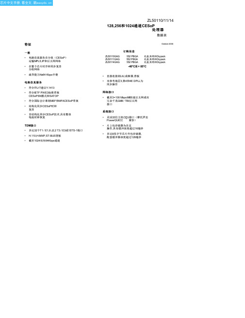
ZL50110/11/14
数据包处理功能
• 灵活多协议数据包封装包括IPv4,IPv6RTP,MPLS,L2TPv3ITU-T Y.1413,IETF CESoPSN模式,IETF SATOP和用户可编程
• 包重测序,允许丢失数据包检测 • 利用出口队列四大类服务优先级可编程机制(WFQ和SP) • 传入分组层2,3,4灵活分类,和5 • 最多支持通过分组交换网络128单独CESoP连接
• 结构感知TDM电路仿真服务在分组交换网络(CESoPSN模式) - 选秀ietfpwe3-cesopsn
该ZL50110/11/14提供高达三倍100 MbpsMII端口或双冗余1000 MbpsGMII / TBI端口.
所述ZL50110/11/14包含一系列每个TDM流强大时钟恢复机制,允许在源时钟频率,可以忠实在目地产生 ,实现更高系统性能和质量.定时使用RTP或类似协议进行,双方自适应和差分时钟恢复方案包括,允许客户选择 正确方案应用.一个外部提供时钟,也可以用于驱动ZL50110/11/14TDM接口.
设备
ZL50114 ZL50110
ZL50111
TDM接口
4 T1,4 E1或1 J 2流或 4 MVIP / ST-BUS流以2.048 Mbps或 1 H.110 / H-MVIP / ST-BUS流在8.192 Mbps
8 T1,8个E1或2 J2流或 8 MVIP / ST-BUS流以2.048 Mbps或 2 H.110 / H-MVIP / ST-BUS流在8.192 Mbps
2.0物理规格. . . . . . . . . . . . . . . . . . . . . . . . . . . . . . . . . . . . . . . . . . . . . . . . . . . . . . . . . . . . . . . . . . 12
PB58,PB58A, 规格书,Datasheet 资料
CAUTION
The PB58 is constructed from MOSFET transistors. ESD handling procedures must be observed.
100 2200
2 320 100
1
VS–15 VS–11
*
*
*
*
2.0
75
*
*
*
240
*
*
*
V V V A V/µs pF µs kHz kHz MHz
±156
±60 ±150
*
11
12
14
18
*
*
V
*
mA
*
mA
*
*
mA
TEST CONDITIONS2
Full temperature range3
AV = 3 AV = 10 f = 10kHz, AVCL = 10, CC = 22pF f = 200kHz, AVCL = 10, CC = 22pF
Io = 1.5A (PB58), 2A (PB58A) Io = 1A Io = .1A
Copyright © Cirrus Logic, Inc. 2012 (All Rights Reserved)
芯天下--/
MAR 20121 APEX − PB58UREVM
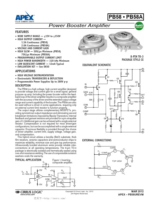
PB58 • PB58A
ABSOLUTE MAXIMUM RATINGS
±.75 ±1.75
–4.5 –7
25
50
*
3
3
10
25
*
±10 ±15
安利索变频器说明书正文(安利索自产)资料
注意危险1.确认及安装注意2.布线注意3.操作和运行4.维护和检查5.其它危险注意危险危险危险目录1.安全注意事项-------------------------------------------------------------------------------1 2.目录------------------------------------------------------------------------------------------2 3.接线------------------------------------------------------------------------------------------4 3—1 变频器接线图---------------------------------------------------------------------4 3—2 控制器接线--------------------------------------------------------------------------5 4.操作-------------------------------------------------------------------------------------------6 4—1 各按键功能及指示-----------------------------------------------------------------6 4—2 基本操作-----------------------------------------------------------------------------7 4—3 系统参数-----------------------------------------------------------------------------7 5.其它参数------------------------------------------------------------------------------------10 5—1 相关技术参数-----------------------------------------------------------------------10 5—2 电气参数-----------------------------------------------------------------------------10 6.调试说明------------------------------------------------------------------------------------11 6-1两个关键词的解释---------------------------------------------------------------------11 6-2门机控制器调试的具体步骤---------------------------------------------------------11 7.故障处理-------------------------------------------------------------------------------------13 8.其它---------------------------------------------------------------------------------------------13 8—1 废物处理------------------------------------------------------------------------------13 8—2 咨询修理------------------------------------------------------------------------------13 9.附页---------------------------------------------------------------------------------------------14 附页1:门机安装注意事项-----------------------------------------------------------------14 附页2:双折门机直梁安装示意图--------------------------------------------------------15 附页3:轿顶安装示意图--------------------------------------------------------------------161-1开箱●首先检查确认货物是否在运输途中被破坏。
卡兹兹 58MXA 型号高效熔炉产品说明书

Catalog No. 530-145 1-0349004DP25 CARRIER CORPORATIONFOR SERVICE OR REPAIR, FOLLOW THESE STEPS IN ORDER:FIRST: Contact the installer. You may find their name on the furnace or in your Homeowner’s Packet. If the installer’s name is not known, call your builder or home retailer if yours is a new residence.SECOND: Contact the nearest distributor. (See telephone yellow pages.)THIRD: Contact:CARRIER CORPORATIONConsumer RelationsP.O. Box 4808Syracuse, New York 13221Phone: 1-800-227-7437Model No. ____________________________________________ Unit Serial No. ________________________________________Date of Installation _____________________________________ Installed by ___________________________________________Name of Owner _______________________________________ Address of Installation __________________________________Deluxe Condensing Gas Furnace Limited Warranty(Model 58MXA)FIVE-YEAR LIMITED WARRANTY – CARRIER CORPORATION (hereinafter referred to as “Company”) warrants this furnace to be free from defects in material and workmanship. If a defect is found within five years from date of original installation of furnace (whether or not actual use begins on that date) Company will provide a new or remanufactured part, at Company’s sole option, to replace any defective part, without charge for the part itself.LIMITED WARRANTY ON HEAT EXCHANGER ONLY:A. 20-YEAR LIMITED WARRANTY ON HEAT EXCHANGER ONLY - Where the owner of the dwelling is not the original purchaser and inmulti-family dwellings (i.e., where the furnace services more than one dwelling unit) and in non-residential and other applications, the Company warrants the heat exchanger against defects in material and workmanship for a period of twenty years from the date of original installation.B. LIFETIME LIMITED WARRANTY ON HEAT EXCHANGER ONLY - The Company warrants to the original purchaser, during his or herlifetime, that the heat exchanger will be free from defects material and workmanship; provided, however, this warranty shall apply only to the original installation of the furnace in a single family dwelling (i.e., where the furnace services only one dwelling unit) used without interruption as the purchaser’s principal residence.The Company's warranty obligation in A or B above shall be, at its sole option, to provide a new heat exchanger without charge for the heat exchanger itself or allow a credit in the amount of the then current factory selling price of an equivalent heat exchanger toward the purchase price of a new Carrier furnace [without charge if the retail price of a new furnace is less than the factory price of a new or equivalent heat exchanger].None of these warranties include labor or other costs incurred for diagnosing, repairing, removing, installing, shipping, servicing or handling of either defective parts, or replacement parts, or new units.WARRANTY CONDITIONS:1.Warranties apply only to furnaces in their original installation location.2. Installation, use, care, and maintenance must be normal and in accordance with instructions contained in the Owner’s Manual and Company’sservice information.3. Defective parts must be returned to the distributor through a registered servicing dealer for credit.4. All work shall be performed during normal working hours.LIMITATIONS OF WARRANTIES – ALL IMPLIED WARRANTIES (INCLUDING IMPLIED WARRANTIES OF MERCHANTABILITY AND FITNESS FOR A PARTICULAR PURPOSE) ARE HEREBY LIMITED IN DURATION TO THE PERIOD FOR WHICH THE LIMITED WARRANTYIS GIVEN AND APPLIES. SOME STATES DO NOT ALLOW LIMITATIONS ON HOW LONG AN IMPLIED WARRANTY LASTS, SO THE ABOVE MAY NOT APPLY TO YOU. THE EXPRESSED WARRANTIES MADE IN THIS WARRANTY ARE EXCLUSIVE AND MAY NOT BE ALTERED, ENLARGED, OR CHANGED BY ANY DISTRIBUTOR, DEALER, OR OTHER PERSON, WHATSOEVER.COMPANY WILL NOT BE RESPONSIBLE FOR:1. Normal maintenance as outlined in the installation and servicing instructions or Owner’s Manual, including filter cleaning and/or replacement andlubrication.2. Damage or repairs required as a consequence of faulty installation, misapplication, abuse, improper servicing, unauthorized alteration or improperoperation.3. Failure to start due to voltage conditions, blown fuses, open circuit breakers, or damages due to the inadequacy or interruption of electrical service.4. Damage as a result of floods, winds, fires, lightning, accidents, corrosive environments or other conditions beyond the control of Company.5. Parts not supplied or designated by Company, or damages resulting from their use.6. Company furnaces installed outside the continental U.S.A., Alaska, Hawaii, and Canada.7. Electricity or fuel costs, or increases in electricity or fuel costs from any reason whatsoever, including additional or unusual use of supplementalelectric heat.8. ANY SPECIAL INDIRECT OR CONSEQUENTIAL PROPERTY OR COMMERCIAL DAMAGE OF ANY NATURE WHATSOEVER. Some states donot allow the exclusion of incidental or consequential damages, so the above limitation may not apply to you.This Warranty gives you specific legal rights, and you may also have other rights which vary from state to state.。
2N6058中文资料(microsemi)中文数据手册「EasyDatasheet - 矽搜」
极性:NPN(见
安装硬件:可选绝缘体和金属板螺钉向厂家咨询
重量:约15克
在最后一页.
可靠性水平
JAN = JAN水平 JANTX = JANTX水平 JANTXV = JANTXV水平
空白=商业
JEDEC类 型 号 (see 电气特性
表)
PART命名法
JAN 2N6058 (e3)
符
IB IC IE TC V CB
输出电容
VCB = 10 V,IE = 0,F = 100千赫≤˚F≤1兆赫
2N6058和2N6059
@ T A = +25 Co除非另有说明
符
Min. Max. Unit
2N6058 V(BR)CEO
80
2N6059
100
V
2N6058 2N6059
ICEO
1.0
mA
1.0
2N6058 2N6059
V CBO
V EBO PT
Value -55到+175
1.0 12 80 100 80 100 5 150 75
Unit oC oC/W A V
V
V W
T4-LDS-0307,修订版1(8/5/13)
芯片中文手册,看全文,戳
2N6058和2N6059
机械和包装
案例:行业标准TO-204AD(TO-3),密封,0.040英寸直径引脚. 表面处理:焊接浸锡铅镍镀合金 52或符合RoHS标准雾锡电镀.每MIL-STD-750方法2026焊 性.
集电极电源电压:施加到连接到所述集电极电路电源电压. 集电极 - 发射极电压:集电极和发射极之间直流电压. 集电极 - 发射极电压,基极开路:集电极和发射极端时基极端是开路之间电压.
Magistra TAV 58 产品说明书
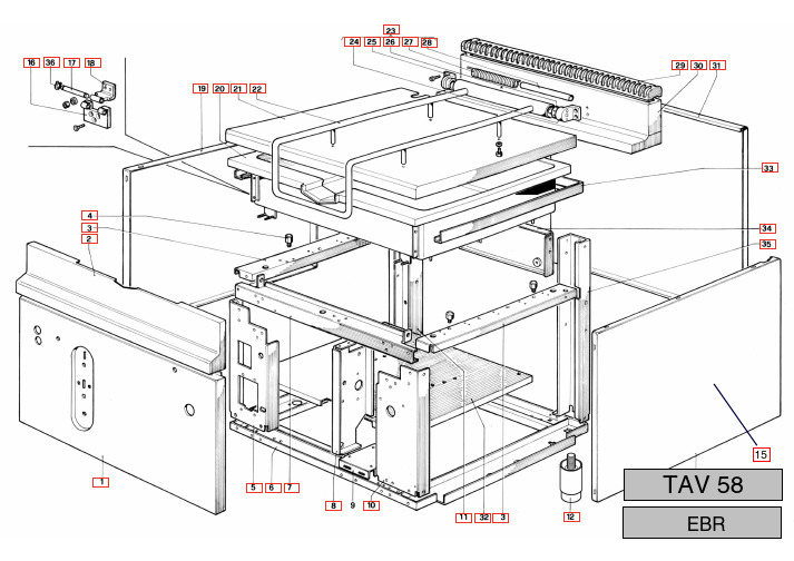
15 TAV 58EBRTABLE POS.CODE ITALIAN ENGLISH FRANÇAIS DEUTSCH MAGISTRA TAV. 581PABF800294FACCIATA EST.EBRA EXTERNAL FACE DEVANTURE EXTERNE AUSSENVORDERWANDMAGISTRA TAV. 581PABF800293FACCIATA EST.EBR EXTERNAL FACE DEVANTURE EXTERNE AUSSENVORDERWANDMAGISTRA TAV. 582GABF800110AS.CRUSCOTTO GBR CONTROL PANEL PANNEAU DE COMMANDE STIRNBRETTMAGISTRA TAV. 582GABF800110AS.CRUSCOTTO GBR CONTROL PANEL PANNEAU DE COMMANDE STIRNBRETTMAGISTRA TAV. T.UN.PIANTANE BRG SIDE CROSSBAR CROISILLON LATERAL QUERSTRÄNGENMAGISTRA TAV. T.UN.PIANTANE BRG SIDE CROSSBAR CROISILLON LATERAL QUERSTRÄNGENMAGISTRA TAV. 584RTBF900119V.M8X10 APPOG.VASCA BRE TANKE SUPPORT SUPPORT CUVE REGLERHALTERUNGMAGISTRA TAV. 584RTBF900119V.M8X10 APPOG.VASCA BRE TANKE SUPPORT SUPPORT CUVE REGLERHALTERUNGMAGISTRA TAV. 585PABF900226PIANTANA ANT.SX BRG FRONT LEFT SUPPORT COLONNE AVANT GAUCHE SÄULE VORNE LINKSMAGISTRA TAV. 585PABF900226PIANTANA ANT.SX BRG FRONT LEFT SUPPORT COLONNE AVANT GAUCHE SÄULE VORNE LINKSMAGISTRA TAV. 586GABF800108AS.BASAM.GBR ACC.BASE SOUBASSEMENT UNTERGESTELLMAGISTRA TAV. 586GABF800108AS.BASAM.GBR ACC.BASE SOUBASSEMENT UNTERGESTELLMAGISTRA TAV. 587PABF900247TRA.ANT.UN.PIANTANE BRE BACK CROSSBAR CROISILLON ANTÉRIEUR VORDERER QUERTRÄGER MAGISTRA TAV. 587PABF900247TRA.ANT.UN.PIANTANE BRE BACK CROSSBAR CROISILLON ANTÉRIEUR VORDERER QUERTRÄGER MAGISTRA TAV. 588PABF900220SUP.CENTRALE PERNO RIB.BRG CENTRAL SUPPORT SUPPORT CENTRAL MITTLERE HALTERUNGMAGISTRA TAV. 588PABF900220SUP.CENTRALE PERNO RIB.BRG CENTRAL SUPPORT SUPPORT CENTRAL MITTLERE HALTERUNGMAGISTRA TAV. 589PABF800290SUP.MOTORE BRGA MOTOR SUPPORT SUPPORT MOTEUR HALTERUNGMAGISTRA TAV. 5810PABF900225PIANTANA ANT.DX BRG FRONT RIGHT SUPPORT COLONNE AVANT DROITE SÄULE VORNE RECHTSMAGISTRA TAV. 5810PABF900225PIANTANA ANT.DX BRG FRONT RIGHT SUPPORT COLONNE AVANT DROITE SÄULE VORNE RECHTSMAGISTRA TAV. 5811PABF900331PIANTANA POST.SX BRG REAR LEFT SUPPORT COLONNE ARRIÈRE GAUCHE SÄULE HINTEN LINKSMAGISTRA TAV. 5811PABF900331PIANTANA POST.SX BRG REAR LEFT SUPPORT COLONNE ARRIÈRE GAUCHE SÄULE HINTEN LINKSMAGISTRA TAV. 5816RTBF900101CERN.FISSA ANT.VASCA BRG ZINC.FIXED BASIN HINGE CHARNIÈRE FIXE CUVE FESTES WANNENSCHARNIER MAGISTRA TAV. 5816RTBF900101CERN.FISSA ANT.VASCA BRG ZINC.FIXED BASIN HINGE CHARNIÈRE FIXE CUVE FESTES WANNENSCHARNIER MAGISTRA TAV. 5817RTBF900099PERNO CERN.ANT.VASCA BRG HINGE PIN TOURILLON CHARNIÈRE SCHARNIERZAPFENMAGISTRA TAV. 5817RTBF900099PERNO CERN.ANT.VASCA BRG HINGE PIN TOURILLON CHARNIÈRE SCHARNIERZAPFENMAGISTRA TAV. 5818RTBF900100CERN.MOBILE ANT.VASCA BRG ZINC MOBIL BASIN HINGE CHARNIÈRE MOBILE CUVE BEWEGLICHES WANNENSCHARNIER MAGISTRA TAV. 5818RTBF900100CERN.MOBILE ANT.VASCA BRG ZINC MOBIL BASIN HINGE CHARNIÈRE MOBILE CUVE BEWEGLICHES WANNENSCHARNIER MAGISTRA TAV. 5819PABF800286FIANCO SX GBR LEFT SIDE CÔTÉ GAUCHE LINKE SEITEMAGISTRA TAV. 5819PABF800286FIANCO SX GBR LEFT SIDE CÔTÉ GAUCHE LINKE SEITEMAGISTRA TAV. 5820RTBF800300VASCA EBR TANK CUVE WANNEMAGISTRA TAV. 5820RTBF800300VASCA EBR TANK CUVE WANNEMAGISTRA TAV. 5821GABF800106AS.COPERCHIO GBR COVER COUVERCLE TOPFDECKELMAGISTRA TAV. 5821GABF800106AS.COPERCHIO GBR COVER COUVERCLE TOPFDECKELMAGISTRA TAV. 5822RTCP800031*MANIGLIA COP.G100COVER HANDLE POIGNÉE DU COUVERCLE DECHEKGRIFFMAGISTRA TAV. 5822RTCP800031*MANIGLIA COP.G100COVER HANDLE POIGNÉE DU COUVERCLE DECHEKGRIFFMAGISTRA TAV. PLETA INOX COP.GBR COVER HINGE CHARNIÈRE COUVERCLE ABDECKUNGSSCHARNIER MAGISTRA TAV. PLETA INOX COP.GBR COVER HINGE CHARNIÈRE COUVERCLE ABDECKUNGSSCHARNIER MAGISTRA TAV. 5824RTCP800030*TERMINALE DX CERN.COP.G100HINGE RIGHT TERMINAL TERMINAL DROITE CHARNIÉRE RECHTER ENDVERSCHLUßMAGISTRA TAV. 5824RTCP800030*TERMINALE DX CERN.COP.G100HINGE RIGHT TERMINAL TERMINAL DROITE CHARNIÉRE RECHTER ENDVERSCHLUßMAGISTRA TAV. 5826RTCP800028*REGOLAT.MOLLA CERN.COP.G100COVE SPRING ADJ. DEVICE REGULATEUR RESSORT COUVERCLE FEDERREGLER ABDECKUNG MAGISTRA TAV. 5826RTCP800028*REGOLAT.MOLLA CERN.COP.G100COVE SPRING ADJ. DEVICE REGULATEUR RESSORT COUVERCLE FEDERREGLER ABDECKUNG MAGISTRA TAV. 5827RTBF800103MOLLA CERNIERA COP.BRG/GBR SPRIENG FOR COVER HINGE RÉSSORT POUR CHARNIÉRE SCHARNIERFEDERMAGISTRA TAV. 5827RTBF800103MOLLA CERNIERA COP.BRG/GBR SPRIENG FOR COVER HINGE RÉSSORT POUR CHARNIÉRE SCHARNIERFEDERMAGISTRA TAV. 5828RTCP800027*GUIDA MOLLA CERN.COP.G100HINGE SPRING GUIDE GUIDE POUR RÉSSORT CHARNIÉRE COUVER TÜRFEDERFÜHRUNGTABLE POS.CODE ITALIAN ENGLISH FRANÇAIS DEUTSCH MAGISTRA TAV. 5828RTCP800027*GUIDA MOLLA CERN.COP.G100HINGE SPRING GUIDE GUIDE POUR RÉSSORT CHARNIÉRE COUVER TÜRFEDERFÜHRUNG MAGISTRA TAV. 5829GACU800014AS.GRIGLIA CAM.G4SF SMALT.CHIMNEY GRILL GRILLE DE LA CHEMINÉE SCHORNSTEINROST MAGISTRA TAV. 5829GACU800014AS.GRIGLIA CAM.G4SF SMALT.CHIMNEY GRILL GRILLE DE LA CHEMINÉE SCHORNSTEINROST MAGISTRA TAV. 5830GABF800111AS.CAMINETTO SUP.GBR SUPERIOR CHIMNEY CHEMINÉE SUPERIEURE OBERER SCHORNSTEIN MAGISTRA TAV. 5830GABF800111AS.CAMINETTO SUP.GBR SUPERIOR CHIMNEY CHEMINÉE SUPERIEURE OBERER SCHORNSTEIN MAGISTRA TAV. 5831PABF800280POSTERIORE INOX GBR STAINLESS STEEL BACK PANEL PANNEAU POSTÉRIEURE INOX INOX-RÜCKWANDMAGISTRA TAV. 5831PABF800280POSTERIORE INOX GBR STAINLESS STEEL BACK PANEL PANNEAU POSTÉRIEURE INOX INOX-RÜCKWANDMAGISTRA TAV. 5832PABF900243PI.INF.INOX BRE LOWER PLAN PLAN INFERIEUR UNTERE EBENEMAGISTRA TAV. 5832PABF900243PI.INF.INOX BRE LOWER PLAN PLAN INFERIEUR UNTERE EBENEMAGISTRA TAV. 5833GABF800107AS.CONTORNO R/OLIO GBR OIL COLLECTION EDGE CONTOURÖLSAMMELRANDMAGISTRA TAV. 5833GABF800107AS.CONTORNO R/OLIO GBR OIL COLLECTION EDGE CONTOURÖLSAMMELRANDMAGISTRA TAV. 5834GABF800112AS.TRA.POST.UN.PIANTANE GBR REAR CROSSBAR CROISILLON POSTERIEURE HINTERE QUERTRÄGER MAGISTRA TAV. 5834GABF800112AS.TRA.POST.UN.PIANTANE GBR REAR CROSSBAR CROISILLON POSTERIEURE HINTERE QUERTRÄGER MAGISTRA TAV. 5835PABF900227PIANTANA POST.DX BRG REAR RIGHT SUPPORT COLONNA ARRIÉRE DROITE SÄULE HINTEN RECHTS MAGISTRA TAV. 5835PABF900227PIANTANA POST.DX BRG REAR RIGHT SUPPORT COLONNA ARRIÉRE DROITE SÄULE HINTEN RECHTS MAGISTRA TAV. 5836RTMIN00123SEEGER ESTERNO E10.SEEGER Ø 10SEEGER Ø 10SEEGER Ø 10MAGISTRA TAV. 5836RTMIN00123SEEGER ESTERNO E10.SEEGER Ø 10SEEGER Ø 10SEEGER Ø 10TAV 57EBRTABLE POS.CODE ITALIAN ENGLISH FRANÇAIS DEUTSCH MAGISTRA TAV. 571RTBF900104SUP.OSCILL.FORI/16 BRG LEN206OSCILLATING SUPPORT SUPPORT OSCILLANT GELENKLAGERMAGISTRA TAV. 571RTBF900104SUP.OSCILL.FORI/16 BRG LEN206OSCILLATING SUPPORT SUPPORT OSCILLANT GELENKLAGERMAGISTRA TAV. 571RTBF900104SUP.OSCILL.FORI/16 BRG LEN206OSCILLATING SUPPORT SUPPORT OSCILLANT GELENKLAGERMAGISTRA TAV. 571RTBF900104SUP.OSCILL.FORI/16 BRG LEN206OSCILLATING SUPPORT SUPPORT OSCILLANT GELENKLAGERMAGISTRA TAV. 572RTBF900106RIBALTATORE VASCA BRG ZINC.TANK TILTING DEVICE BASCULEUR BAC WANNENDIPPVORRICHTUNG MAGISTRA TAV. 572RTBF900106RIBALTATORE VASCA BRG ZINC.TANK TILTING DEVICE BASCULEUR BAC WANNENDIPPVORRICHTUNG MAGISTRA TAV. 572RTBF900106RIBALTATORE VASCA BRG ZINC.TANK TILTING DEVICE BASCULEUR BAC WANNENDIPPVORRICHTUNG MAGISTRA TAV. 572RTBF900106RIBALTATORE VASCA BRG ZINC.TANK TILTING DEVICE BASCULEUR BAC WANNENDIPPVORRICHTUNG MAGISTRA TAV. 573RTBF900110PROLUNGA RIBALT.BRG FILTING DEVICE EXTENSION RALLONGE BASCULEUR KIPPVORRICHTUNGSVERLÄNGERUNG MAGISTRA TAV. 573RTBF900110PROLUNGA RIBALT.BRG FILTING DEVICE EXTENSION RALLONGE BASCULEUR KIPPVORRICHTUNGSVERLÄNGERUNG MAGISTRA TAV. 573RTBF900110PROLUNGA RIBALT.BRG FILTING DEVICE EXTENSION RALLONGE BASCULEUR KIPPVORRICHTUNGSVERLÄNGERUNG MAGISTRA TAV. 573RTBF900110PROLUNGA RIBALT.BRG FILTING DEVICE EXTENSION RALLONGE BASCULEUR KIPPVORRICHTUNGSVERLÄNGERUNG MAGISTRA TAV. 574RTBF900096PERNO FIS.PROLUNGA RIB.BRG FILTING DEVICE PLUG PRISE BASCULEUR KIPPVORRICHTUNGSSTIFT MAGISTRA TAV. 574RTBF900096PERNO FIS.PROLUNGA RIB.BRG FILTING DEVICE PLUG PRISE BASCULEUR KIPPVORRICHTUNGSSTIFT MAGISTRA TAV. 574RTBF900096PERNO FIS.PROLUNGA RIB.BRG FILTING DEVICE PLUG PRISE BASCULEUR KIPPVORRICHTUNGSSTIFT MAGISTRA TAV. 574RTBF900096PERNO FIS.PROLUNGA RIB.BRG FILTING DEVICE PLUG PRISE BASCULEUR KIPPVORRICHTUNGSSTIFT MAGISTRA TAV. 575RTMIN00123SEEGER ESTERNO E10.SEEGER Ø 10SEEGER Ø 10SEEGER Ø 10MAGISTRA TAV. 575RTMIN00123SEEGER ESTERNO E10.SEEGER Ø 10SEEGER Ø 10SEEGER Ø 10MAGISTRA TAV. 575RTMIN00123SEEGER ESTERNO E10.SEEGER Ø 10SEEGER Ø 10SEEGER Ø 10MAGISTRA TAV. 575RTMIN00123SEEGER ESTERNO E10.SEEGER Ø 10SEEGER Ø 10SEEGER Ø 10MAGISTRA TAV. 576RTBF900102PERNO FIS.RIDUTTORE BRG ZINC.REDUCTION ATTACHMENT PIN TOURILLON FIXATION RÉDUCTEUR KIPPVORRICHTUNGMAGISTRA TAV. 576RTBF900102PERNO FIS.RIDUTTORE BRG ZINC.REDUCTION ATTACHMENT PIN TOURILLON FIXATION RÉDUCTEUR KIPPVORRICHTUNGMAGISTRA TAV. 576RTBF900102PERNO FIS.RIDUTTORE BRG ZINC.REDUCTION ATTACHMENT PIN TOURILLON FIXATION RÉDUCTEUR KIPPVORRICHTUNGMAGISTRA TAV. 576RTBF900102PERNO FIS.RIDUTTORE BRG ZINC.REDUCTION ATTACHMENT PIN TOURILLON FIXATION RÉDUCTEUR KIPPVORRICHTUNGMAGISTRA TAV. 577RTBF900109RIDUTTORE BRG/GBR REDUCTION UNIT RÉDUCTEUR UNTERSETZUNGSGETRIEBE MAGISTRA TAV. 577RTBF900109RIDUTTORE BRG/GBR REDUCTION UNIT RÉDUCTEUR UNTERSETZUNGSGETRIEBE MAGISTRA TAV. 577RTBF900109RIDUTTORE BRG/GBR REDUCTION UNIT RÉDUCTEUR UNTERSETZUNGSGETRIEBE MAGISTRA TAV. 577RTBF900109RIDUTTORE BRG/GBR REDUCTION UNIT RÉDUCTEUR UNTERSETZUNGSGETRIEBE MAGISTRA TAV. 578RTMIN00226CHIAVETTA INC.BRG/8X7X40 ACC.KEY 8X7X40CLAVETTE 8X7X40FEDER 8X7X40MAGISTRA TAV. 578RTMIN00226CHIAVETTA INC.BRG/8X7X40 ACC.KEY 8X7X40CLAVETTE 8X7X40FEDER 8X7X40MAGISTRA TAV. 578RTMIN00226CHIAVETTA INC.BRG/8X7X40 ACC.KEY 8X7X40CLAVETTE 8X7X40FEDER 8X7X40MAGISTRA TAV. 578RTMIN00226CHIAVETTA INC.BRG/8X7X40 ACC.KEY 8X7X40CLAVETTE 8X7X40FEDER 8X7X40MAGISTRA TAV. 579RTBF800093VOLANTINO GBR HANDWAL VOLANT HANDWELMAGISTRA TAV. 579RTBF800093VOLANTINO GBR HANDWAL VOLANT HANDWELMAGISTRA TAV. 5710RTBF900105BUSSOLA PROL.VOLANT.BRG FLYIMPELLER EXTENSION BUSHING FOURREAU ROLLONGE VOLANT HANDRADVERLÄNGERUNGSBUCHSE MAGISTRA TAV. 5710RTBF900105BUSSOLA PROL.VOLANT.BRG FLYIMPELLER EXTENSION BUSHING FOURREAU ROLLONGE VOLANT HANDRADVERLÄNGERUNGSBUCHSE MAGISTRA TAV. 5711RTMIN00250CHIAVETTA INC.BRGA/6X6X39 ACC.KEY 6X6X39CLAVETTE 6X6X39FEDER 6X6X39MAGISTRA TAV. 5711RTMIN00250CHIAVETTA INC.BRGA/6X6X39 ACC.KEY 6X6X39CLAVETTE 6X6X39FEDER 6X6X39MAGISTRA TAV. 5712RTBF900124PULEGGIA RIDUTT.BRGA D210/TZ REDUCTION UNIT PULLEY POULIE RÉDUTEUR RIEMENSCHEIBEMAGISTRA TAV. 5712RTBF900124PULEGGIA RIDUTT.BRGA D210/TZ REDUCTION UNIT PULLEY POULIE RÉDUTEUR RIEMENSCHEIBEMAGISTRA TAV. 5713GABF900121MANIGLIA SOCCORSO BRGA ZINC.B.EMERGENCY HANDLE POIGNÉE DE SECOURS NOT-GRIFFMAGISTRA TAV. 5713GABF900121MANIGLIA SOCCORSO BRGA ZINC.B.EMERGENCY HANDLE POIGNÉE DE SECOURS NOT-GRIFFMAGISTRA TAV. 5714RTBF900125CINGHIA TRAPEZ.BRGA T.Z36X915VBELT COURROI TRAPÉZOIDALE KEILRIEMENMAGISTRA TAV. 5715RTMIN00251*CHIAVETTA INC.BRGA/5X5X25 ACC KEY 5X5X25CLAVETT 5X5X25FEDER 5X5X25TABLE POS.CODE ITALIAN ENGLISH FRANÇAIS DEUTSCHMAGISTRA TAV. 5715RTMIN00251*CHIAVETTA INC.BRGA/5X5X25 ACC KEY 5X5X25CLAVETT 5X5X25FEDER 5X5X25MAGISTRA TAV. 5716RTBF900123PULEGGIA MOTORE BRGA D50/TZ MOTOR PULLEY POULIE MOTEUR MOTOR-RIEMENSCHEIBEMAGISTRA TAV. 5716RTBF900123PULEGGIA MOTORE BRGA D50/TZ MOTOR PULLEY POULIE MOTEUR MOTOR-RIEMENSCHEIBEMAGISTRA TAV. 5717RTCU800156*CONDENS.MOT.450V/8MF MOTOR GUARD PROTECTION MOTEUR MOTORSCHUTZMAGISTRA TAV. 5717RTCU800156*CONDENS.MOT.450V/8MF MOTOR GUARD PROTECTION MOTEUR MOTORSCHUTZMAGISTRA TAV. 5718RTBF900122MOTORE+COND.SOLL.VASCA BRGA TANK TILTING MOTOR MOTEUR RELEVAGE BAC WANNENHEBEMOTORMAGISTRA TAV. 5718RTBF900122MOTORE+COND.SOLL.VASCA BRGA TANK TILTING MOTOR MOTEUR RELEVAGE BAC WANNENHEBEMOTORMAGISTRA TAV. 5719RTBF800123PULSANTE GBRA ZB2BA26PUSH BUTTON BOUTON DRUCKKNOPFMAGISTRA TAV. 5719RTBF800123PULSANTE GBRA ZB2BA26PUSH BUTTON BOUTON DRUCKKNOPFMAGISTRA TAV. 5720PABF900346SQ.FIS.PULSANTI BRGA BRACKET FOR PUSH BOTTON EGUERRE FIXATION BOUTONS WINKELEISENMAGISTRA TAV. 5720PABF900346SQ.FIS.PULSANTI BRGA BRACKET FOR PUSH BOTTON EGUERRE FIXATION BOUTONS WINKELEISENMAGISTRA TAV. 5721RTBF800125CONTATTI PULS.GBRA ZB2BZ105PUSH BUTTON CONTACT CONTACTS BOUTONS DRUCKKNOPFKONTAKTEMAGISTRA TAV. 5721RTBF800125CONTATTI PULS.GBRA ZB2BZ105PUSH BUTTON CONTACT CONTACTS BOUTONS DRUCKKNOPFKONTAKTEMAGISTRA TAV. 5722PABF900347PROTEZ.PULSANTI BRGA PUSHBOTTON GUARD PROTECTION BOUTONS POUSSOIRS SCHUTZVORRICHTUNGMAGISTRA TAV. 5722PABF900347PROTEZ.PULSANTI BRGA PUSHBOTTON GUARD PROTECTION BOUTONS POUSSOIRS SCHUTZVORRICHTUNGMAGISTRA TAV. 5723PABF900353FLANGIA FIS.PUL.RIDUTTORE BRGA PULLEY ATTACHMENT FLANGE BRIDE FIXATION POULIE BEFESTIGUNGSFLANSCH FÜR RIEMENSCHEIBE MAGISTRA TAV. 5723PABF900353FLANGIA FIS.PUL.RIDUTTORE BRGA PULLEY ATTACHMENT FLANGE BRIDE FIXATION POULIE BEFESTIGUNGSFLANSCH FÜR RIEMENSCHEIBETAV 59EBRTABLE POS.CODE ITALIAN ENGLISH FRANÇAIS DEUTSCHMAGISTRA TAV. 591RTCP800018RUB.ACQ.G100 17CR905M WATER TAP ROBINET DE L'EAU WASSERHAHNMAGISTRA TAV. 591RTCP800018RUB.ACQ.G100 17CR905M WATER TAP ROBINET DE L'EAU WASSERHAHNMAGISTRA TAV. 592RTBF800126NIPLES COMP.CIL/F/D10 01141021NIPLES FOR PIPE Ø 10NIPLES POUR TUYAU Ø 10NIPPEL FÜR SCHLAUCH Ø 10MAGISTRA TAV. 592RTBF800126NIPLES COMP.CIL/F/D10 01141021NIPLES FOR PIPE Ø 10NIPLES POUR TUYAU Ø 10NIPPEL FÜR SCHLAUCH Ø 10MAGISTRA TAV. 593PABF900131SQ.FIS.RESIST.FT2E ELEMENT FIXING BRACKET EGUERRE DE FIXAGE POUR RÉSISTANCE WIDERSTANDSBEFESTIGUNGSWINKEL MAGISTRA TAV. 593PABF900131SQ.FIS.RESIST.FT2E ELEMENT FIXING BRACKET EGUERRE DE FIXAGE POUR RÉSISTANCE WIDERSTANDSBEFESTIGUNGSWINKEL MAGISTRA TAV. 594PABF900202TU.AL.EROG.ACQ.V.BRG TANK FILLING PIPE TUYAU REMPLISSAGE BAC WANNENFÜLLROHRMAGISTRA TAV. 594PABF900202TU.AL.EROG.ACQ.V.BRG TANK FILLING PIPE TUYAU REMPLISSAGE BAC WANNENFÜLLROHRMAGISTRA TAV. 595PABF800292TU.AL.RUB.ACQ.GBR WATER FEEDING PIPE TUYAU DISTRIBUTION EAU HAHNVERSORGUNGSROHRMAGISTRA TAV. 595PABF800292TU.AL.RUB.ACQ.GBR WATER FEEDING PIPE TUYAU DISTRIBUTION EAU HAHNVERSORGUNGSROHRMAGISTRA TAV. 596GABF800035AS.ATT.ACQUA GBM90/GBR WATER CONNECTION ATTAQUE DE L'EAU WASSERANSCHLUSSMAGISTRA TAV. 596GABF800035AS.ATT.ACQUA GBM90/GBR WATER CONNECTION ATTAQUE DE L'EAU WASSERANSCHLUSSMAGISTRA TAV. 597RTCU900012BICONO D.10DOUBLE CONE D.10BICONE D.10DOPPELKONUS D.10MAGISTRA TAV. 597RTCU900012BICONO D.10DOUBLE CONE D.10BICONE D.10DOPPELKONUS D.10MAGISTRA TAV. 598RTCU900013CALOTTA D.10NUT ECROU MUTTERMAGISTRA TAV. 598RTCU900013CALOTTA D.10NUT ECROU MUTTERMAGISTRA TAV. 599RTBF800041EROGATORE ACQ.GC45 3/8"C44MB09WATER DISTRIBUTOR DISTRIBUTION POUR L'EAU WASSERVERSORGERMAGISTRA TAV. 599RTBF800041EROGATORE ACQ.GC45 3/8"C44MB09WATER DISTRIBUTOR DISTRIBUTION POUR L'EAU WASSERVERSORGERMAGISTRA TAV. 5910RTBF800026R.BRE 1.5KW230OVER HEATING ELECT. 1500W 240V.RÉSISTNCE ELECTRIQUE 1500W 240V.ELEKT. WIDERSTÄNDE 1500W 240V. MAGISTRA TAV. 5910RTBF800026R.BRE 1.5KW230OVER HEATING ELECT. 1500W 240V.RÉSISTNCE ELECTRIQUE 1500W 240V.ELEKT. WIDERSTÄNDE 1500W 240V. MAGISTRA TAV. 5911PABF900246CONT.INT.IS.RES.BRE EL. RESISTOR INSULATING CONTAINER BOÎTIER ISOLANT RÉSISTANCES EL.ISOLIERMITTELBEHÄLTER EL. WIDERSTÄNDE MAGISTRA TAV. 5911PABF900246CONT.INT.IS.RES.BRE EL. RESISTOR INSULATING CONTAINER BOÎTIER ISOLANT RÉSISTANCES EL.ISOLIERMITTELBEHÄLTER EL. WIDERSTÄNDE MAGISTRA TAV. 5912MPIS000003IS.INSULFRAX/1,26X1,10X9SP WATER FEEDING PIPE TUYAU DISTRIBUTION EAU HAHNVERSORGUNGSROHRMAGISTRA TAV. 5912MPIS000003IS.INSULFRAX/1,26X1,10X9SP WATER FEEDING PIPE TUYAU DISTRIBUTION EAU HAHNVERSORGUNGSROHRMAGISTRA TAV. 5913PABF900244CONT.EST.IS.RES.BRE EXTERIOR CONTAINER FOR INSULATION BOÎTIER EXTERNE POUR ISOLANT EXTERNER ISOLIERMITTELBEHÄLTER MAGISTRA TAV. 5913PABF900244CONT.EST.IS.RES.BRE EXTERIOR CONTAINER FOR INSULATION BOÎTIER EXTERNE POUR ISOLANT EXTERNER ISOLIERMITTELBEHÄLTER MAGISTRA TAV. 5914PABF900248PIASTRINA FORO CONT.EST.IS.BRE HOLE COVER PLATE PLAQUETTE BOUCHE-TROU LOCHABDECKUNGMAGISTRA TAV. 5914PABF900248PIASTRINA FORO CONT.EST.IS.BRE HOLE COVER PLATE PLAQUETTE BOUCHE-TROU LOCHABDECKUNGMAGISTRA TAV. 5915PABF900245PROTEZ.MORS.RES.BRE EL. RESISTOR TERMINAL STRIP GNARD PROTECTION BORNIER RÉSISTANCES SCHUTZVORRICHTUNG KLEMMBRETTER MAGISTRA TAV. 5915PABF900245PROTEZ.MORS.RES.BRE EL. RESISTOR TERMINAL STRIP GNARD PROTECTION BORNIER RÉSISTANCES SCHUTZVORRICHTUNG KLEMMBRETTER MAGISTRA TAV. 5916PABF900230SCATOLA P/COMANDI BRG CONTROL BOX BOÎTER PORTE-COMMANDES STEUERUNGSKASTENMAGISTRA TAV. 5916PABF900230SCATOLA P/COMANDI BRG CONTROL BOX BOÎTER PORTE-COMMANDES STEUERUNGSKASTENMAGISTRA TAV. 5917PABF900045*PIANTANA SX FACC.BM4G WATER FEEDING PIPE TUYAU DISTRIBUTION EAU HAHNVERSORGUNGSROHRMAGISTRA TAV. 5917PABF900045*PIANTANA SX FACC.BM4G WATER FEEDING PIPE TUYAU DISTRIBUTION EAU HAHNVERSORGUNGSROHRMAGISTRA TAV. 5918GABF900117AS.COPERCHIO SCAT.P/COM.BRG BOX COVER COUVERCLE BOÎTER KASTENDECKELMAGISTRA TAV. 5918GABF900117AS.COPERCHIO SCAT.P/COM.BRG BOX COVER COUVERCLE BOÎTER KASTENDECKELMAGISTRA TAV. 5919RTCU700212COMM.BM2E 4922015705 C COMMUTATOR COMMUTATEUR KOMMUTATORMAGISTRA TAV. 5919RTCU700212COMM.BM2E 4922015705 C COMMUTATOR COMMUTATEUR KOMMUTATORMAGISTRA TAV. 5920RTCU900290LAMP.SP.VERDE/250V/TBF013.SF6GREEN WARNING LAMP LAMPE TEMOIN VERTE GRÜNE KONTROLLEUCHTEMAGISTRA TAV. 5920RTCU900290LAMP.SP.VERDE/250V/TBF013.SF6GREEN WARNING LAMP LAMPE TEMOIN VERTE GRÜNE KONTROLLEUCHTEMAGISTRA TAV. .EF90 0+1 NERO COMMUTATOR KNOB BOUTON DU COMMUTATEUR KOMMUTATORKUGELGRIFFMAGISTRA TAV. .EF90 0+1 NERO COMMUTATOR KNOB BOUTON DU COMMUTATEUR KOMMUTATORKUGELGRIFFMAGISTRA TAV. 5922RTCU900072LAMP.SP.GIALLA/250V/TBF013.SF6YELLOW WARNING LAMP LAMPE TÉMOIN JAUNE GELBE KONTROLLEUCHTEMAGISTRA TAV. 5923RTCU700085T.E.C4EF70 5519062802THERMOSTAT THERMOSTAT THERMOSTATTABLE POS.CODE ITALIAN ENGLISH FRANÇAIS DEUTSCH MAGISTRA TAV. 5923RTCU700085T.E.C4EF70 5519062802THERMOSTAT THERMOSTAT THERMOSTATMAGISTRA TAV. 5924RTBF800085MANOP.TERM.E.GBR 0+8 ROSSO THERMOSTAT KNOB BOUTON DU THERMOSTAT THERMOSTATKUGELGRIFF MAGISTRA TAV. 5924RTBF800085MANOP.TERM.E.GBR 0+8 ROSSO THERMOSTAT KNOB BOUTON DU THERMOSTAT THERMOSTATKUGELGRIFF MAGISTRA TAV. 5925RTBF800192T.L.EBR/T420 5532582804RELAY RELAIS RELAISMAGISTRA TAV. 5925RTBF800192T.L.EBR/T420 5532582804RELAY RELAIS RELAISMAGISTRA TAV. 5926RTBF800153*RELAIS EBR SN20CXAC230V1A1B RELAY RELAIS RELAISMAGISTRA TAV. 5926RTBF800153*RELAIS EBR SN20CXAC230V1A1B RELAY RELAIS RELAISMAGISTRA TAV. 5927RTBF800149*MORSETTIERA EBR+SIMB/1-12 C TERMINAL BLOC 12 POLE GROUPE DE CONNECTION DE CABLES KLEMMENBREIT 12 POLIG MAGISTRA TAV. 5927RTBF800149*MORSETTIERA EBR+SIMB/1-12 C TERMINAL BLOC 12 POLE GROUPE DE CONNECTION DE CABLES KLEMMENBREIT 12 POLIG MAGISTRA TAV. 5928RTBF800138F/CAVOPG21 53015050+D5*******C CABLE CLAMB Ø 9FIXE-CABLE Ø 9KABELHALTER Ø 9 MAGISTRA TAV. 5928RTBF800138F/CAVOPG21 53015050+D5*******C CABLE CLAMB Ø 9FIXE-CABLE Ø 9KABELHALTER Ø 9 MAGISTRA TAV. 5929RTCU700102PASSACAVO D9+DADO GEW52002CABLE-GUIDE Ø 9PASSE-CABLE Ø 9KABELRINNE Ø 9MAGISTRA TAV. 5929RTCU700102PASSACAVO D9+DADO GEW52002CABLE-GUIDE Ø 9PASSE-CABLE Ø 9KABELRINNE Ø 9MAGISTRA TAV. 5930RTCU700103PASSACAVO PG21+DADO GW52006CABLE GUIDE PASSE-CABLE KABELRINNEMAGISTRA TAV. 5930RTCU700103PASSACAVO PG21+DADO GW52006CABLE GUIDE PASSE-CABLE KABELRINNEMAGISTRA TAV. 5931RTBF800113MICROINT.SOLL.VASCA GBR C7DZN MICROSWITCH MICRO-INTERRUPTEUR MIKRO SCHALTER MAGISTRA TAV. 5931RTBF800113MICROINT.SOLL.VASCA GBR C7DZN MICROSWITCH MICRO-INTERRUPTEUR MIKRO SCHALTER。
MAA50-2S151515SBN中文资料
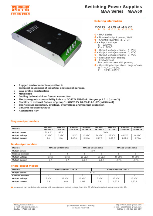
Single-output modelsModule МАА50- 1S03S ХХ МАА50- 1S05S ХХ МАА50- 1S12S ХХ МАА50- 1S15S ХХ МАА50- 1S24S ХХ МАА50- 1S27S ХХМАА50- 1S48S ХХ МАА50- 1S68S ХХ Output power 26,4 W 40 W 50 W Output voltage 3,3 VDC 5 VDC12 VDC15 VDC24 VDC27 VDC48 VDC68 VDCOutput current8 A8 А 4,17 А 3,33 А 2,27 А 1,85 А 1,04 А 0,73 АDual-output modelsModule МАА50-2S0505S ХХ МАА50-2S1212S ХХМАА50-2S1515S ХХOutput power 50 WChannel number 1 2 1 2 1 2 Output voltage 5 VDC 5 VDC 12 VDC 12 VDC15 VDC 15 VDC Output current5 А 5 А 2,1 А 2,1 А 1,67 А 1,67 АTriple-output modelsModule МАА50-3S051212S ХХМАА50-3S051515S ХХOutput power 50 WChannel number 1 2 3 1 2 3Output voltage 5 VDC12 VDC12 VDC5 VDC15 VDC15 VDCOutput current5 А 1,04А 1,04А 5 А 0,83 А 0,83 Аby request can be delivered modules with non-standard output voltage from 3 to 70 VDC and maximal output current to 8А.Ordering informationМАА 50 – 3 S 05 15 15 S U Nc d e f g h i j k lc - MAA Seriesd - Nominal output power, Watte - Channel quantity (1, 2, 3)f - - Input voltageS – 220VAC K – 115VACg - Output voltage channel 1, VDC h - Output voltage channel 2, VDC i - Output voltage channel 3, VDC j - Execution with sealing k - EmbodimentB – uniform case with primingl - Operating temperature range of caseN - - 40°С…+85°С P - - 50°С…+85°С• Rugged environment in operation intechnical equipment of industrial and special purpose. • Low-profile construction • Metal case• Cooling by heat sink or free air convection• Electromagnetic compatibility index to GOST V 25803-91 for group 1.2.1 (curve 2) • Stability to external factors of group 1U GOST RV 20.39.414.1-97 (additional) • Short circuit protection, overload, overvoltage and thermal protection • Galvanic isolated outputs •Acceptance «5»Температура окружающей среды Токр, С9080706050403020100-10-20-30-40-50Выходная мощность, Вт6050403020100Input specificationsParameter Conditions of dimensions MIN NOM MAX UnitS 187 220 242 VACSteady-state deviationК 80 115 140 VAC S 176 264 VACInput voltageTransient deflection, 1 secК 80 150 VAC SInput frequencyК47 400 440 HzOutput specificationsParameterConditions of dimensions MIN NOM MAX Unit Single-output execution (Inom 10 – 100%) ±3 % Output 1 multi-output execution(Inom 10 – 100%) ±3 %Uout2&3 differs from Uout1 less than 20% Output 2 and 3 multi-output execution(Inom 10 – 100%)±13 %Output 1 multi-output execution (Inom 30 – 100%) ±3 %Total output voltage instabilityUout2&3differs fromUout1 more than 20% Output 2 and 3 multi-output execution(Inom 50-100%) ±15 %Output voltage pulsations ripple(peak-to-peak)Dimension by device for pulsation control2% Uout.nom.Current overload protection actuation level110 % Iout.nom. Short circuit protection Autorepair 150 % Iout.nom. Overvoltage protection 120 % Uout.nom.Thermal protection90-95°CGeneral specificationsParameterConditions of dimensions MIN NOM MAX Unit- operating of case N P – 40 – 50 +85+85°C– power loss See diagram Temperature– storage – 50 +85 °CEfficiency 78 % Conversion frequency 50 kHz~ in/out 1500 VAC ~ in/case 1500 VAC~ out/case 500 VDC Isolation~ out/out 500 VDCInsulation resistance Voltage 500VDC 20 Ohm High humidity Temperature 35°С 98 % Cyclic overpatching of temperature – 60 +85 °C Multiple mechanical shocks Speeding-up 15g 2 15 ms Sinusoidal vibration Speeding-up 5g 50 500 Hz Atmosphere pressure 6х104 1,2х105 Pa Time to failure Temperature 35°C 105 hour Mass 0,4 kg all specifications redused for normal climatic conditions, Uin.nom., Iout.nom., if it is not specified differently.Power loss diagramFree airconvectionWith heat sinkAmbient temperature Tamb, °CO u t p u t p o w e r , WOutput settings№ pin1 2 3 4 5 6 7 8 9 Single-channel case ~IN (N) ~IN (L) +out1 +out1 +out1 -out1 -out1 -out1 Dual-channel case ~IN (N) ~IN (L) +out1 +out1 -out1 -out1 -out2 +out2 Triple-channelcase~IN (N)~IN (L)-out3+out3+out1-out1-out2+out2Switching on standart diagramFU in – current safety device 1A for input voltage 220VAC, 2A for input voltage 115VAC.S out – ceramic condenser capacity 0,47-15 mcF with corresponding operating voltage to decrease high-frequency noise level.S out2 – electronic condenser capacity 22-100 mcF in consideration with operating voltage and polarity. It makes for purpose to decrease dynamic instability when module work at dynamic load.+Out -Out ~In (L) ~In (N) Power module R heat CaseСout1 Сout2~In (L)~In (N)ground FU inSingle, Dual, and Triple-output execution SBNSingle, Dual, and Triple-output execution SVN (with flexible erection joints)The Flexible erection fjoints by length (100±5)mm is executed by wire section (0,5...1,5)mm2.。
118JB120R5A0A1中文资料

Resistance Range1 ohm through 20,000 ohms (linear taper) Resistance ToleranceStandard:±20%Special:±10%Power Rating, Watts2 watts @ 55°C derated to no load @ 105°C,linear taper, bushing mounted control onsteel panel 4"x4" x .050"(101.6mm x 101.6mm x 1.27mm).Voltage RatingTerminals to mounting surface (insulated types only):High pot test, one minute — 900 VACOperating Maximum — 500 VDCAcross end terminals:Determined by resistance value andwattage rating Resistance TapersStandard: LinearTaps AvailableNoneIncorporated Fixed ResistorA fixed resistor can be incorporated at the endof CW or CCW rotation to a minimum of 15% ofthe total resistance value. The rotation isshortened by an amount proportional to the ratioof the fixed resistor to the total resistance value. Angle of RotationTotal Rotation: 270°±5°Rotational TorqueTurning Torque: 1/2 to 10 in-oz. (36-720 gf-cm)4 in-oz. (4.61 Kgf-cm)Electrical and Mechanical SpecificationsStop StrengthOrdering InformationTerminal InformationInsulated Construction (Standard)The contactor is insulated from the base and connected to the center terminal on the insulated construction. This construction can be supplied with the center terminal and one end terminal at either end of the resistance element or with the center terminal and terminals at both ends of the resistance element.Grounded Construction (Optional)The grounded construction is supplied without a center terminal and the contactor is connected to the case. This construction can be furnished with one end terminal at either end of the resistance element or with terminals at both ends of the element.Bushing InformationStandard:3/8"-32 UNEF-2A thread, .375" (9.53mm)or .250" (6.35mm) long. M9 x 0.75available.Special:As required in increments of 1/16" (1.58mm) Locating LugsStandard Position:Left side (with terminals down)supplied, unless otherwise specified.Other Positions:Available with right side only, bothleft and right, or without lugs.Electrical and Mechanical SpecificationsCLEARANCE HOLE FOR 3/8-32 THREADED BUSHINGCTS SERIES TYPE 118。
松下伺服马达A5中文选型手册
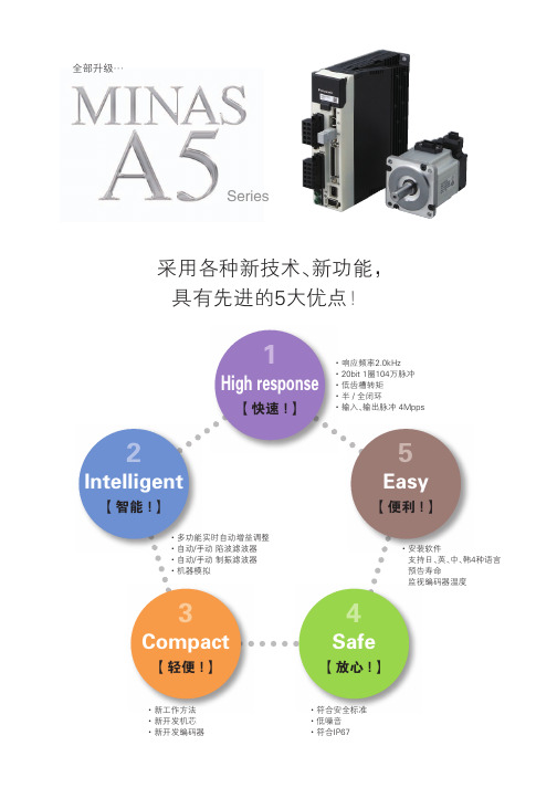
.*/"4" ጆѴNJֵ̖ࠓ
1
ྱཁ̭ፀ
)JHISFTQPOTF
Ǘঋᤳ ǘ
" ̾ज़ֵ̖
ֽःᮟည )[
ֽःᮟည L)[
ၸᜈᎵ Ӧ࠭ͳ҃ᤴᜈᎵNjᜈNjӉᜈኍ
ࠃဗᛠˉణঋᄉᤳऎֽःᮟည L)[
࿗ࠑधԦᄉКள -4* ଡᰳᤁኪᤳऎὋՎௐᦠܫ۲̅ᣀᅽ
ґᯟᄉᰳֽःଌ҃ҩᑞnj᧓ၸᛠˉణঋᄉᤳऎ֖߿ֽͮःবὋ
Ǘఄᑞ ǘ
"
"
ܲҩᑞࠃௐ ᒬҮܘᄝុஞ
Үͺࣰ໎NjϢൢௐᄉҮͯὀ ᎕ᆀ˿ᰳዴऎ߿ͮௐᫍὀ ᧓ၸ࿗ྱᄉζՁူܪశὋधԦѢКளᄉ ʹᑡу CJU ᎃᆉ٧nj
̾ज़"ۋ QS ὺʹᑡуὼ
" QS
ὺʹᑡуὼ
ͯᴐമᣀᅽ
ͯᴐമᣀᅽ
ၸᜈᎵ Ӧ࠭ͳ҃ᤴᜈᎵNjᜈNjࣽNjጛ፤ኍ
电机
电机规格 ............................................................................................................................35 通用规格 .......................................................................................................................36 电机规格说明 ..................................................................................................................104
SMAJ5.0A-TR中文资料

SMAJ5.0A-TR,CA-TR SMAJ188A-TR,CA-TRTRANSIL TM®PEAK PULSE POWER : 400 W (10/1000µs)STAND OFF VOLTAGE RANGE :From 5V to 188V.UNI AND BIDIRECTIONAL TYPES LOW CLAMPING FACTOR FAST RESPONSE TIMEJEDEC REGISTERED PACKAGE OUTLINE FEATURESSMA(JEDEC D0214 AC)Symbol ParameterValue Unit P PP Peak pulse power dissipation (see note 1)Tj initial = T amb 400W P Power dissipation on infinite heatsink T amb = 50°C 3.3W I FSM Non repetitive surge peak forward current for unidirectional types tp = 10msTj initial = T amb40A T stg T j Storage temperature range Maximum junction temperature- 65 to + 175150°C °C T LMaximum lead temperature for soldering during 10 s.260°CNote 1 : For a surge greater than the maximum values, the diode will fail in short-circuit.ABSOLUTE MAXIMUM RATINGS (T amb = 25°C)DESCRIPTIONThe SMAJ series are TRANSIL TM diodes designed specifically for protecting sensitive equipment against transient overvoltages. The SMA package allows save spacing on high density printed circuit boards.Transil diodes provide high overvoltage protection by clamping action. Their instantaneous response to transient overvoltages makes them particularly suited to protect voltage sensitive devices such as MOS Technology and low voltage supplied IC’s.September 1998 Ed: 5A Symbol ParameterValue Unit R th (j-l)Junction to leads30°C/W R th (j-a)Junction to ambient on printed circuit on recommended pad layout120°C/WTHERMAL RESISTANCES 1/5II F V F V CLV BRV RMI PPI RMVSymbol ParameterV RM Stand-off voltage V BR Breakdown voltage V CL Clamping voltage I RM Leakage current @ V RM I PPPeak pulse currentαTVoltage temperature coefficient V FForward voltage dropELECTRICAL CHARACTERISTICS (T amb = 25°C)TypesI RM @ V RM V BR @ I R V CL @ I PP V CL @ I PP αT C maxmin maxmaxmaxtyp note210/1000µs 8/20µs note3note4Unidirectional Mark.Bidirectional Mark. µA V V mA V A V A 10-4/°C pF SMAJ5.0A-TR AE SMAJ5.0CA-TR AA 800 5.0 6.4109.243.513.4174 5.73500SMAJ6.0A-TR DUB SMAJ6.0CA-TR DBB 800 6.0 6.71010.338.813.7170 5.93300SMAJ6.5A-TR DUC SMAJ6.5CA-TR DBC 500 6.57.21011.235.714.5160 6.13100SMAJ8.5A-TR DUH SMAJ8.5CA-TR DBH 108.59.44114.427.718.61247.32000SMAJ10A-TR AX SMAJ10CA-TR AC 51011.111723.521.71067.81550SMAJ12A-TR DUK SMAJ12CA-TR DBK 51213.3119.920.125.3918.31325SMAJ13A-TR BG SMAJ13CA-TR BH 11314.4121.518.627.2858.41200SMAJ15A-TR BM SMAJ15CA-TR AJ 11516.7124.416.432.5718.8975SMAJ18A-TR DUQ SMAJ18CA-TR DBQ 11820129.213.739.3599.2800SMAJ20A-TR DUR SMAJ20CA-TR DBR 12022.2132.412.342.8549.4725SMAJ22A-TR DUS SMAJ22CA-TR DBS 12224.4135.511.248.3489.6625SMAJ24A-TR DUT SMAJ24CA-TR DBT 12426.7138.910.350469.6600SMAJ26A-TR DUU SMAJ26CA-TR DBU 12628.9142.19.553.5439.7575SMAJ28A-TR CG SMAJ28CA-TR CH 12831.1145.48.859399.8510SMAJ30A-TR CK SMAJ30CA-TR CL 13033.3148.48.364.3369.9480SMAJ33A-TR CM SMAJ33CA-TR CN 13336.7153.37.569.73310.0450SMAJ40A-TR DUZ SMAJ40CA-TR DBZ 14044.4164.5 6.2842710.1370SMAJ43A-TR EUA SMAJ43CA-TR EBA 14347.8169.4 5.7912510.2350SMAJ48A-TR CX SMAJ48CA-TR CY 14853.3177.4 5.21002310.3320SMAJ58A-TR EUF SMAJ58CA-TR EBF 15864.4193.6 4.31211910.4270SMAJ70A-TR EUI SMAJ70CA-TR EBI 17077.81113 3.51461610.5230SMAJ85A-TR EUL SMAJ85CA-TR EBL 18594.41137 2.91781310.6200SMAJ100A-TR EUN SMAJ100CA-TR EBN 11001111162 2.52121110.7170SMAJ130A-TR EUQ SMAJ130CA-TR EBQ 11301441209 1.9265910.8145SMAJ154A-TR EUT SMAJ154CA-TR EBT 11541711246 1.6317710.8125SMAJ170A-TR SR SMAJ170CA-TR SS 11701891275 1.4353 6.510.8120SMAJ188A-TREUV SMAJ188CA-TR EBV 11882091328 1.4388610.8110Note 2 :Pulse test : t p < 50 ms.Note 3 :∆V BR = αT * (T amb - 25) * V BR (25°C).Note 4 :V R = 0 V, F = 1 MHz. For bidirectional types,capacitance value is divided by 2.10s1000s%I PP 50tPULSE WAVEFORM 10/1000s100SMAJxxxA-TR, CA-TR2/52550751001251501750.00.10.20.30.40.50.60.70.80.91.01.1Ppp[Tj initial]/Ppp[Tj initial=25°C]Tj initial(°C)Fig 1: Peak power dissipation versus initial junction temperature.0.010.101.0010.0010010005000Ppp(W)tp(ms)Fig 2: Peak pulse power versus exponential pulse duration (Tj initial=25°C).1101005000.11.010.0100.0200.0Ipp(A)tp=20µstp=1ms SMAJ5.0A,CASMAJ188A,CASMAJ58A,CASMAJ26A,CASMAJ13A,CAV (V)CL Fig 3: Clamping voltage versus peak pulse current (Tj initial=25°C)Exponential waveform tp=20µs & tp=1ms.1101002001010010005000C(pF)F=1MHzSMAJ5.0ASMAJ188ASMAJ58ASMAJ26A SMAJ13A V (V)R Fig 4-1: Capacitance versus reverse applied voltage (typical values) (SMAJxxA).11010020011010010002000F=1MHzSMAJ5.0CA SMAJ188CASMAJ58CA SMAJ26CA SMAJ13CAC(pF)V (V)R Fig 4-2: Capacitance versus reverse applied voltage (typical values) (SMAJxxCA).SMAJxxxA-TR, CA-TR3/50.40.50.60.70.80.9 1.0 1.1 1.2 1.3 1.40.010.101.0010.00I (A)FM Tj=25°CTj=125°CV (V)FM Fig 5: Peak forward voltage drop versus peak forward current (typical values).1E-21E-11E+01E+11E+25E+20.010.101.00Zth(j-a)/Rth(j-a)tp(s)Fig 6: Relative variation of thermal impedance junction to ambient versus pulse duration.12345405060708090100110120130140Rth(j-a) (°C/W)S(Cu)(cm²)Fig 7: Thermal resistance junction to ambient versus copper surface under each lead (printed circuit board FR4 e(Cu)=35µm).2550751001251501E-11E+01E+11E+21E+32E+3I [Tj] / I [Tj=25°C]R R V < 8.5VBR Tj(°C)V 8.5VBR ≥Fig 8: Relative variation of leakage current versus junction temperature.SMAJxxxA-TR, CA-TR4/5REF.DIMENSIONSMillimeters Inches Min.Max.Min.Max.A11.902.700.0750.106A20.050.200.0020.008b1.25 1.650.0490.065c 0.150.410.0060.016E4.805.600.1890.220E13.954.600.1560.181D 2.25 2.950.0890.116L0.751.600.0300.063Information furnished is believed to be accurate and reliable. However, STMicroelectronics assumes no responsibility for the consequences of use of such information nor for any infringement of patents or other rights of third parties which may result from its use. No license is granted by implication or otherwise under any patent or patent rights of STMicroelectronics.Specifications mentioned in this publication are subject to change without notice. This publication supersedes and replaces all information previously supplied.STMicroelectronics products are not authorized for use as critical components in life support devices or systems without express written approval of STMicroelectronics.The ST logo is a registered trademark of STMicroelectronics © 1998 STMicroelectronics - Printed in Italy - All rights reserved.STMicroelectronics GROUP OF COMPANIESAustralia - Brazil - Canada - China - France - Germany - Italy - Japan - Korea - Malaysia - Malta - Mexico - Morocco -The Netherlands - Singapore - Spain - Sweden - Switzerland - Taiwan - Thailand - United Kingdom - U.S.A.Packaging : standard packaging is in tape and reel.PACKAGE MECHANICAL DATA SMA (Plastic)ECLE1DA1A2bMARKING : Logo, Date Code, Type Code, Cathode Band (for unidirectional types only).FOOTPRINT DIMENSIONS (Millimeter)SMA Plastic.2.40 1.651.45 1.45Weight = 0.068 gORDER CODESM A J 85 C A - TRBIDIRECTIONALNo suffix : UnidirectionalSURFACE MOUNTSTAND OFF VOLTAGE400 WATTSTAPE & REEL SMAJxxxA-TR, CA-TR5/5。
LE5810塔式起重机说明书

LE5810塔式起重机使用说明书上海立尔机械有限公司概述LE5810塔式起重机,是按JG/ T5037-93《塔式起重机分类》标准设计的新型塔式起重机。
LE5810塔机为水平起重臂,小车变幅,上回转自升多用途塔机。
该机的特色有:1.性能参数及技术指标国内领先,达到90年代国际先进水平,最大工作幅度58m,最大起升高度140m。
2.整机外型为国际流行式,非常美观,深受国内外用户的喜爱。
3. 工作方式多,适用范围广。
该机有基础固定,底架固定,外墙附着及行走等工作方式,适用各种不同的施工对象。
独立式的起升高度为40m,附着式是在独立式的基础上,增加塔身标准节和附着装置即可实现,起升高度可达140m。
4. 工作速度高,调速性能好,其中变幅机构、回转机构采用当今国际上最先进的变频无级调速方案,工作更加平稳可靠。
5. 电器控制系统采用专业电器厂引进国外先进技术生产的电器元件,寿命比国产元件长3~4倍,故障少,维修简单,工作可靠。
6.各种安全装置齐备,且为机械式或机电一体化产品,适应于恶劣的施工环境,能确保塔机工作可靠。
7. 坚持吸收采用国内外成熟可靠的先进技术,提高整机的技术水平,采用成熟可靠的先进技术有:1) 专业电器厂引进法国TE公司技术生产的电器元件;2) 引进国外先进技术并国产化了的重量限制器、力矩限制器、高度限位器、幅度限位器、回转限位器、回转、牵引机构的制动器等安全装置。
3) 小车防断绳装置(防溜车)和防断轴装置;4) 起升机构排绳系统;5) 牵引绳张紧系统;6) 刚性双拉杆悬挂大幅度起重臂,起重臂刚度好,自重轻,断面小,风阻小,外形美观,长度有几种变化,满足不同施工需要;7) 司机室独立外置,视野好,内部空间大,给操作者创造良好的工作环境;8) 采用先进的联动台操纵各机构动作,操作容易,维修简单;9) 采用回转限位器,方便了司机从塔机中间的上下通行8. 设计完全符合或优于有关国家标准。
由于该机具有以上特点,因而它适用于高层或超高层民用建筑、桥梁水利工程、大跨度工业厂房以及采用滑模法施工的高大烟囱及筒仓等大型建筑工程中。
SMAJ50中文资料

FeaturesMechanical Data· Plastic package has Underwriters Laboratoryflammability classification 94V-0· Optimized for LAN protection applications· Ideal for ESD protection of data lines in accordance with IEC 1000-4-2 (IEC801-2)· Ideal for EFT protection of data lines in accordance with IEC 1000-4-4 (IEC801-4)· Low profile package with built-in strain relief for surface mounted applications · Glass passivated junction· Low incremental surge resistance, excellent clamping capability· 400W peak pulse power capability with a 10/1000¥ìSwaveform, repetition rate(duty cycle) : 0.01% (300W above 78V)· Very fast response time· High temperature soldering guaranteed : 250¡É/10 seconds at terminalsDevices For Bidirectional ApplicationsMaximum Ratings And Electrical Characteristics· For bi-directional devices, use suffix C or CA (e.g. SMAJ10C, SMAJ10CA). Electrical characteristics apply in both directions.· Case : JEDEC DO-214AC(SMA) molded plastic over passivated chip· Terminals : Solder plated , solderable per MIL-STD-750, method 2026· Polarity : For uni-directional types the band denotesthe cathode, which is positive with respect to the anode under normal TVS operation· Mounting Position : Any· Weight : 0.002 ounce, 0.064 gramPeak pulse power dissipation with a 10/1000¥ìS waveform (Note 1,2. Fig. 1)Peak pulse current with a waveform (Note 1)Typical thermal resistance, junction to lead Typical thermal resistance, junction to ambient (Note 3)Peak forward surge current, 8.3mm single half sine-wave unidirectional only (Note 2)Operating junction and storage temperature rangeP PPM 400Watts SymbolsValuesUnits30I PPM See next tableAmps 40I FSMT J ,T STG120-55 to +150¡É¡É/W ¡É/W Amps (Ratings at 25¡É ambient temperature unless otherwise specified)Notes:(1) Non repetitive current pulse, per Fig.3 and derated above T A =25¡É per Fig.2 Rating is 300W above 78V(2) Mounted on 0.2¡¿0.2"(5.0¡¿5.0mm) copper pads to each terminal (3) Mounted on minimum recommended pad layoutDimensions in inches and (millimeters)DO-214AC (SMA)R¥èJA R¥èJLRatings at 25¡É ambient temperature unless otherwise specified. VF=3.5V at IF=25A (uni-directional only)DeviceBreakdown VoltageMaximum Maximum MaximumDevice Type Marking V (BR)at I T (1)Test Stand-off Reverse Leakage Peak Pulse Surge ClampingCode (V)Current Voltage at V WM Current I PPM Voltage at I PPM UNI BI Max Min I T (mA)V WM (V)I D ( ¥ìA )(3)(A)(2)V C (V)S MAJ 5.0(C )AD WD 6.407.827.0710 5.080041.79.6S MAJ 5.0(C )A (5)AE WE 6.4010 5.080043.59.2S MAJ 6.0(C )AF WF 6.678.157.3710 6.080035.111.4S MA J 6.0(C )A AG WG 6.6710 6.080038.810.3S MAJ 6.5(C )AH WH 7.227.228.8210 6.550032.512.3S MA J 6.5(C )A AK WK 7.9810 6.550035.711.2S MAJ 7.0(C )AL WL 7.789.518.60107.020030.113.3S MA J7.0(C )A AM WM 7.78107.020033.312.0S MAJ 7.5(C )AN WN 8.3310.29.21 1.07.510028.014.3S MA J 7.5(C )A AP WP 8.331.07.510031.012.9S MAJ 8.0(C )AQ WQ 8.8910.99.83 1.08.05026.715.0S MA J 8.0(C )A AR WR 8.891.08.05029.413.6S MAJ 8.5(C )AS WS 9.4411.510.4 1.08.51025.215.9S MA J8.5(C )A AT WT 9.441.08.51027.814.4S MAJ 9.0(C )AU WU 10.012.211.1 1.09.0 5.023.716.9S MA J 9.0(C )A AV WV 10.0 1.09.0 5.026.015.4S MAJ 10(C )AW WW 11.113.612.3 1.010 1.021.318.8S MA J 10(C )A AX WX 11.1 1.010 1.023.517.0S MAJ 11(C )AY WY 12.214.913.5 1.011 1.019.920.1S MA J11(C )A AZ WZ 12.21.011 1.022.018.2S MAJ 12(C )B D XD 13.316.314.7 1.012 1.018.222.0S MA J 12(C )A B E XE 13.31.012 1.020.119.9S MAJ 13(C )B F XF 14.417.615.9 1.013 1.016.823.8S MA J 13(C )A B G XG 14.41.013 1.018.621.5S MAJ 14(C )B H XH 15.619.117.2 1.014 1.015.525.8S MA J14(C )A B K XK 15.61.014 1.017.223.2S MAJ 15(C )B L XL 16.720.418.5 1.015 1.014.926.9S MA J 15(C )A B M XM 16.71.015 1.016.424.4S MAJ 16(C )B N XN 17.821.819.7 1.016 1.013.928.8S MA J 16(C )A B P XP 17.81.016 1.015.426.0S MAJ 17(C )B Q XQ 18.923.120.9 1.017 1.013.130.5S MA J17(C )A B R XR 18.91.017 1.014.527.6S MAJ 18(C )B S XS 20.024.422.1 1.018 1.012.432.2S MA J18(C )A B T XT 20.01.018 1.013.729.2S MAJ 20(C )BU XU 22.227.124.5 1.020 1.011.235.8S MA J20(C )A B V XV 22.21.020 1.012.332.4S MAJ 22(C )B W XW 24.429.826.9 1.022 1.010.239.4S MA 22(C )A B X XX 24.41.022 1.011.335.5S MAJ 24(C )B Y XY 26.732.629.5 1.024 1.09.343.0S MA 24(C )A B Z XZ 26.71.024 1.010.338.9S MAJ 26(C )C D Y D 28.935.331.9 1.026 1.08.646.6S MA 26(C )A C E Y E 28.91.026 1.09.542.1S MAJ 28(C )C F Y F 31.138.034.4 1.028 1.08.050.0S MA 28(C )A C G Y G 31.11.028 1.08.845.4S MAJ 30(C )C H Y H 33.340.736.8 1.030 1.07.553.5S MA 30(C )AC K Y K33.31.0301.08.348.4Notes :(1) P ulse test:t p=50ms (2) S urge current waveform per F ig.3 and derate per F ig.2(3) For bi-directional types having V WM of 10 Volts and less, the I D limit is doubled (4) All terms and symbols are consistent with ANS I/IE E E C 62.35(5) For the bidirectional S MAJ 5.0C A, the maximum V (B R )is 7.25V.Ratings at 25¡É ambient temperature unless otherwise specified. VF=3.5V at IF=25A (uni-directional only)DeviceBreakdown VoltageMaximum Maximum MaximumDevice Type Marking V (BR)at I T (1)Test Stand-off Reverse Leakage Peak Pulse Surge ClampingCode (V)Current Voltage at V WM Current I PPM Voltage at I PPM UNI BI Max Min I T (mA)V WM (V)I D ( ¥ìA)(3)(A)(2)V C (V)S MAJ 33(C )C L Y L 36.744.940.6 1.033 1.0 6.859.0S MA J33(C )A C M Y M 36.71.033 1.07.553.3S MAJ 36(C )C N Y N 40.048.9 1.036 1.0 6.264.3S MA J36(C )A C P Y P 40.0 1.036 1.0 6.958.1S MAJ 40(C )C Q Y Q 44.454.344.2 1.040 1.0 5.671.4S MA J 40(C )A C R Y R 44.41.040 1.0 6.264.5S MAJ 43(C )C S Y S 47.858.449.1 1.043 1.0 5.276.7S MA J43(C )A C T Y T 47.81.043 1.0 5.869.4S MAJ 45(C )C U Y U 50.061.152.8 1.045 1.0 5.080.3S MA J45(C )A C V Y V 50.0 1.045 1.0 5.572.7S MAJ 48(C )C W Y W 53.365.155.3 1.048 1.0 4.785.5S MA J 48(C )A C X Y X 53.3 1.048 1.0 5.277.4S MAJ 51(C )C Y Y Y 56.769.358.9 1.051 1.0 4.491.1S MA J51(C )A C Z Y Z 56.7 1.051 1.0 4.982.4S MAJ 54(C )R D ZD 60.073.362.7 1.054 1.0 4.296.3S MA J54(C )A R E ZE 60.01.054 1.0 4.687.1S MAJ 58(C )R F ZF 64.478.766.3 1.058 1.0 3.9103S MA J 58(C )A R G ZG 64.4 1.058 1.0 4.393.6S MAJ 60(C )R H ZH 66.781.571.2 1.060 1.0 3.7107S MA J60(C )A R K ZK 66.71.060 1.0 4.196.8S MAJ 64(C )R L ZL 71.186.973.7 1.064 1.0 3.5114S MA J64(C )A R M ZM 71.1 1.064 1.0 3.9103S MAJ 70(C )R N ZN 77.895.186.092.195.878.6 1.070 1.0 3.2125S MA J 70(C )A R P ZP 77.81.070 1.0 3.5113S MAJ 75(C )R Q ZQ 83.3102 1.075 1.0 3.0134S MA J75(C )A R R ZR 83.3 1.075 1.0 3.3121S MAJ 78(C )R S ZS 86.7106 1.078 1.0 2.9139S MA J78(C )A R T ZT 86.7 1.078 1.0 3.2126S MAJ 85(C )R U ZU 94.4115104 1.085 1.0 2.0151S MA J 85(C )A R V ZV 94.41.085 1.02.2137S MAJ 90(C )R W ZW 100122111 1.090 1.0 1.9160S MA J 90(C )A R X ZX 1001.090 1.02.1146S MAJ 100(C )R Y ZY 111136123 1.0100 1.0 1.7179S MA J100(C )A R Z ZZ 1111.0100 1.0 1.9162S MAJ 110(C )VD VD 122149135 1.0110 1.0 1.5196S MA J110(C )A S E VE 1221.0110 1.0 1.7177S MAJ 120(C )S F VF 133163147 1.0120 1.0 1.4214S MA 120(C )A VG VG 1331.0120 1.0 1.6193S MAJ 130(C )S H VH 144176159 1.0130 1.0 1.3231S MA 130(C )A VK VK 1441.0130 1.0 1.4209S MAJ 150(C )S L VL 167204185 1.0150 1.0 1.1268S MA 150(C )A VM VM 1671.0150 1.0 1.2243S MAJ 160(C )S N VN 178218197 1.0160 1.0 1.0287S MA 160(C )A S P VP 1781.0160 1.0 1.2259S MAJ 170(C )S Q VQ 189231209 1.0170 1.00.99304S MA 170(C )A S R VR 1891.0170 1.0 1.09275S MAJ 188(C )S T VT 209255 1.0188 1.00.9344S MAJ 188(C )AS S VS2092311.01881.00.91328Notes :(1) P ulse test:t p =50ms(2) S urge current waveform per F ig.3 and derate per F ig.2(3) For bi-directional types having V WM of 10 Volts and less, the I D limit is doubled (4) All terms and symbols are consistent with ANS I/IE E E C 62.35151050100t p , P ulse Duration (sec)Fig. 2 Ð P uls e Derating C urveP P P M , P e a k P u l s e P o w e r (k W )Fig. 1 Ð P eak Puls e P ower R ating Cur veT r a n s i e n t T h e r m a l I m p e d a n c e ( o C /W )Number of C ycles at 60 Hz0.0010.010.11101001000I P P M , P e a k P u l s e C u r r e n t , % I R S M。
SMBJ58CA中文资料

B
Dim A
SMB Min 3.30 4.06 1.91 0.15 5.00 0.10 0.76 2.00 Max 3.94 4.70 2.21 0.31 5.59 0.20 1.52 2.62
1. Valid provided that terminals are kept at ambient temperature. 2. Measured with 8.3ms single half sine-wave. Duty cycle = 4 pulses per minute maximum. 3. Unidirectional units only.
DS19002 Rev. 11 - 2
1 of 3
SMBJ5.0(C)A - SMBJ170(C)A
元器件交易网
Part Number Add C For Bi-Directional (Note 4) SMBJ5.0(C)A SMBJ6.0(C)A SMBJ6.5(C)A SMBJ7.0(C)A SMBJ7.5(C)A SMBJ8.0(C)A SMBJ8.5(C)A SMBJ9.0(C)A SMBJ10(C)A SMBJ11(C)A SMBJ12(C)A SMBJ13(C)A SMBJ14(C)A SMBJ15(C)A SMBJ16(C)A SMBJ17(C)A SMBJ18(C)A SMBJ20(C)A SMBJ22(C)A SMBJ24(C)A SMBJ26(C)A SMBJ28(C)A SMBJ30(C)A SMBJ33(C)A SMBJ36(C)A SMBJ40(C)A SMBJ43(C)A SMBJ45(C)A SMBJ48(C)A SMBJ51(C)A SMBJ54(C)A SMBJ58(C)A SMBJ60(C)A SMBJ64(C)A SMBJ70(C)A SMBJ75(C)A SMBJ78(C)A SMBJ85(C)A SMBJ90(C)A SMBJ100(C)A SMBJ110(C)A SMBJ120(C)A SMBJ130(C)A SMBJ150(C)A SMBJ160(C)A SMBJ170(C)A Reverse Standoff Voltage VRWM (V) 5.0 6.0 6.5 7.0 7.5 8.0 8.5 9.0 10.0 11.0 12.0 13.0 14.0 15.0 16.0 17.0 18.0 20.0 22.0 24.0 26.0 28.0 30.0 33.0 36.0 40.0 43.0 45.0 48.0 51.0 54.0 58.0 60.0 64.0 70.0 75.0 78.0 85.0 90.0 100.0 110.0 120.0 130.0 150.0 160.0 170.0 Breakdown Voltage VBR @ IT (Note 5) Min (V) 6.40 6.67 7.22 7.78 8.33 8.89 9.44 10.00 11.10 12.20 13.30 14.40 15.60 16.70 17.80 18.90 20.00 22.20 24.40 26.70 28.90 31.10 33.30 36.70 40.00 44.40 47.80 50.00 53.30 56.70 60.00 64.40 66.70 71.10 77.80 83.30 86.70 94.40 100.0 111.0 122.0 133.0 144.0 167.0 178.0 189.0 Max (V) 7.23 7.67 8.30 8.95 9.58 10.23 10.82 11.50 12.80 14.40 15.30 16.50 17.90 19.20 20.50 21.70 23.30 25.50 28.00 30.70 33.20 35.80 38.30 42.20 46.00 51.10 54.90 57.50 61.30 65.20 69.00 74.60 76.70 81.80 89.50 95.80 99.70 108.20 115.50 128.00 140.00 153.00 165.50 192.50 205.00 217.50 Test Current IT(mA) 10 10 10 10 1.0 1.0 1.0 1.0 1.0 1.0 1.0 1.0 1.0 1.0 1.0 1.0 1.0 1.0 1.0 1.0 1.0 1.0 1.0 1.0 1.0 1.0 1.0 1.0 1.0 1.0 1.0 1.0 1.0 1.0 1.0 1.0 1.0 1.0 1.0 1.0 1.0 1.0 1.0 1.0 1.0 1.0 Max. Reverse Leakage @ VRWM(Note 6) IR (mA) 800 800 500 200 100 50 10 5.0 5.0 5.0 5.0 5.0 5.0 5.0 5.0 5.0 5.0 5.0 5.0 5.0 5.0 5.0 5.0 5.0 5.0 5.0 5.0 5.0 5.0 5.0 5.0 5.0 5.0 5.0 5.0 5.0 5.0 5.0 5.0 5.0 5.0 5.0 5.0 5.0 5.0 5.0 Max. Clamping Max. Peak Pulse Current Voltage @ Ipp Ipp VC (V) 9.2 10.3 11.2 12.0 12.9 13.6 14.4 15.4 17.0 18.2 19.9 21.5 23.2 24.4 26.0 27.6 29.2 32.4 35.5 38.9 42.1 45.4 48.4 53.3 58.1 64.5 69.4 72.7 77.4 82.4 87.1 93.6 96.8 103.0 113.0 121.0 126.0 137.0 146.0 162.0 177.0 193.0 209.0 243.0 259.0 275.0 (A) 65.2 58.3 53.6 50.0 46.5 44.1 41.7 39.0 35.3 33.0 30.2 27.9 25.8 24.0 23.1 21.7 20.5 18.5 16.9 15.4 14.2 13.2 12.4 11.3 10.3 9.3 8.6 8.3 7.7 7.3 6.9 6.4 6.2 5.8 5.3 4.9 4.7 4.4 4.1 3.7 3.4 3.1 2.9 2.5 2.3 2.2 Marking Code BIAE AG AK AM AP AR AT AV AX AZ BE BG BK BM BP BR BT BV BX BZ CE CG CK CM CP CR CT CV CX CZ DE DG DK DM DP DR DT DV DX DZ EE EG EK EM EP ER UNIKE KG KK KM KP KR KT KV KX KZ LE LG LK LM LP LR LT LV LX LZ ME MG MK MM MP MR MT MV MX MZ NE NG NK NM NP NR NT NV NX NZ PE PG PK PM PP PR
SM540A中文资料
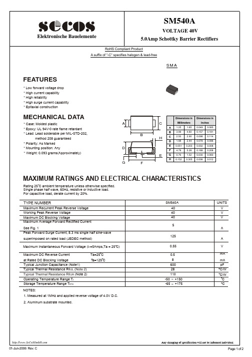
Page 2 of 2
SMA
FEATURES
* Low forward voltage drop * High current capability * High reliability * High surge current capability * Epitaxial construction
MECHANICAL DATA
0.7
Forward Voltage (V)
Junction Capacitance (pF)
600
400
Typical Reverse Characteristic
200
10
100¢J
0 0.1 1 10 100
Revise Voltage (%)
1 75¢J
200
Reverse Current(mA)
NOTES:
SM540A 40 40 40
UNITS V V V
5
125
A A V mA mA pF C/W C/W C C
0.55 0.5 8 600 28 118 -50 ~ +150 -65 ~ +175
Ta=25 C Ta=125 C
1. Measured at 1MHz and applied reverse voltage of 4.0V D.C. 2. Aluminum substrate mounted.
0.001 1
10
20
30
40
50
Number of Cycles at 60Hz
Reverse Voltage(V)
Any changing of specification will not be informed individual
SMBJ58A中文资料
SMBJ5V0(C)A - SMBJ170(C)ADISCLAIMERFAIRCHILD SEMICONDUCTOR RESERVES THE RIGHT TO MAKE CHANGES WITHOUT FURTHER NOTICE TO ANY PRODUCTS HEREIN TO IMPROVE RELIABILITY , FUNCTION OR DESIGN. FAIRCHILD DOES NOT ASSUME ANY LIABILITY ARISING OUT OF THE APPLICATION OR USE OF ANY PRODUCT OR CIRCUIT DESCRIBED HEREIN; NEITHER DOES IT CONVEY ANY LICENSE UNDER ITS PATENT RIGHTS, NOR THE RIGHTS OF OTHERS.TRADEMARKSThe following are registered and unregistered trademarks Fairchild Semiconductor owns or is authorized to use and is not intended to be an exhaustive list of all such trademarks.LIFE SUPPORT POLICYFAIRCHILD S PRODUCTS ARE NOT AUTHORIZED FOR USE AS CRITICAL COMPONENTS IN LIFE SUPPORTDEVICES OR SYSTEMS WITHOUT THE EXPRESS WRITTEN APPROVAL OF FAIRCHILD SEMICONDUCTOR CORPORATION.As used herein:1. Life support devices or systems are devices orsystems which, (a) are intended for surgical implant intothe body, or (b) support or sustain life, or (c) whosefailure to perform when properly used in accordancewith instructions for use provided in the labeling, can be reasonably expected to result in significant injury to the user.2. A critical component is any component of a life support device or system whose failure to perform can be reasonably expected to cause the failure of the life support device or system, or to affect its safety or effectiveness.PRODUCT STATUS DEFINITIONS Definition of Terms Datasheet Identification Product Status DefinitionAdvance InformationPreliminaryNo Identification Needed Obsolete This datasheet contains the design specifications for product development. Specifications may change in any manner without notice.This datasheet contains preliminary data, andsupplementary data will be published at a later date.Fairchild Semiconductor reserves the right to make changes at any time without notice in order to improve design.This datasheet contains final specifications. Fairchild Semiconductor reserves the right to make changes at any time without notice in order to improve design.This datasheet contains specifications on a product that has been discontinued by Fairchild semiconductor.The datasheet is printed for reference information only.Formative or In Design First ProductionFull ProductionNot In ProductionImpliedDisconnect ISOPLANARLittleFETMicroFETMicroPakMICROWIREMSXMSXProOCXOCXProOPTOLOGIC âOPTOPLANARFACT FACT Quiet Series FAST âFASTr FRFET GlobalOptoisolator GTO HiSeCI 2CRev. I2ACEx ActiveArray Bottomless CoolFET CROSSVOLT DOME EcoSPARK E 2CMOS TM EnSigna TMPACMANPOP Power247 PowerTrench âQFET QS QT Optoelectronics Quiet Series RapidConfigure RapidConnect SILENT SWITCHER âSMART START SPMStealthSuperSOT -3SuperSOT -6SuperSOT -8SyncFET TinyLogic âTruTranslation UHC UltraFET âVCXAcross the board. Around the world. The Power FranchiseProgrammable Active Droop。
MTA58多回转绝对型编码器使用说明书
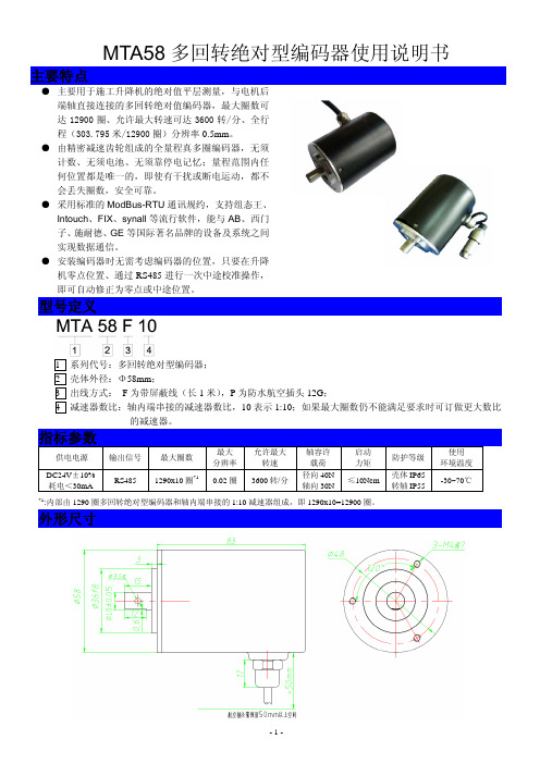
1 系列代号:多回转绝对型编码器; 2 壳体外径:Φ58mm; 3 出线方式: F 为带屏蔽线(长 1 米),P 为防水航空插头 12G; 4 减速器数比:轴内端串接的减速器数比,10 表示 1:10;如果最大圈数仍不能满足要求时可订做更大数比
的减速器。
指标参数
供电电源
DC24V±10% 耗电<30mA
4、 如果升降机驱动齿轮/齿条或减速器间隙量(回差)较大,控制系统可根据运动方向和楼层进行修正、以便 提高平层控制精度。
5、 除了按 MODBUS 通讯协议的被动模式外,还可选择自由通讯协议的主动模式(编码器每间隔 15mS 主动发送 一组动态数据)。
6、 读取数据、中途校准位置、改变信号方向、中途校准指令等通讯协议,请见“MTA58 多转绝对型编码器通讯 说明书”。
2、 因为内部由 1290 圈多回转绝对型编码器和轴内端串接的 1:N(1:10)减速器组成,输出数据由多圈(整数圈) 0~1290 和单圈绝对值 0~1024bit 的二组数据组成,数据处理时将读取的单圈绝对值换算为小数圈值(当前值 ÷1024)、加上多圈值后,乘以 N(10)即可得出实际(电机轴)圈数,再根据升降机的减速器速比和驱动齿轮 即可换算出升降机的行程。比如:升降机电机到驱动齿轮的减速器为 1:16、驱动齿轮模数为 8 齿数 15,设 读取并换算为电机轴的动态总圈数值为 Q、升降机零点位置时编码器圈数为 100 圈,则计算的行程公式为: S=(Q‐100)÷16×(8×15×3.14) (mm)。
磁干扰环境下,对编码器 DC24V 供电要采用隔离电源、外部延长的通讯线最好使用双屏蔽电缆等措施。 4、 编码器外壳和屏蔽线外层网线要做到良好接地,防止雷击或高压静电对编码器电路造成损坏! 5、 除了上述中途校准(黄线)和信号方向(绿线)允许接地外,编码器其它任何信号线禁止相互短接,通电后还
Extreme Flight RC 1 60 Slick 580 EXP ARF 动力模型机器人无人

60" Slick 580 EXP ARF Instruction ManualCopyright 2017 Extreme Flight RCPlease take a few moments to read this instruction manual before beginning assembly. We have outlined a fast, clear and easy method to assemble this aircraft and familiarizing yourself with this process will aid in a quick, easy build.Please read the following paragraph before beginning assembly of your aircraft!THIS IS NOT A TOY! Serious injury, destruction of property, or even death may result from the misuse of this product. Extreme Flight RC is providing you, the consumer, with a very high quality model aircraft component kit, from which you, the consumer, will assemble a flying model. It is beyond our control to monitor the finished aircraft you produce. Extreme Flight RC will in no way accept or assume responsibility or liability for damages resulting from the use of this user assembled product. This aircraft should be flown in accordance with the AMA safety code. It is highly recommended that you join the Academy of Model Aeronautics in order to be properly insured and operate your model at AMA sanctioned flying fields only. If you are not willing to accept ALL liability for the use of this product, please return it to the place of purchase immediately. Extreme Flight RC, Ltd. guarantees this kit to be free of defects in materials and workmanship for a period of 30 DAYS from the date of purchase. All warranty claims must be accompanied by the original dated receipt. This warranty is extended to the original purchaser of the aircraft kit only. Extreme Flight RC in no way warranties its aircraft against flutter. We have put these aircraft through the most grueling flight tests imaginable and have not experienced any control surface flutter. Proper servo selection and linkage set-up is absolutely essential. Inadequate servos or improper linkage set up may result in flutter and possibly the complete destruction of your aircraft. If you are not experienced in this type of linkage setup or have questions regarding servo choices, please contact us at ************************or 770-887-1794. It is your responsibility to ensure the airworthiness of your model.Items needed for completion:✓Masking tape.✓Hobby knife with #11 blades.✓Thin and medium CA. We highly recommend Mercury M5T thin and M100XF medium formulas as well as the Mercury glue tips.✓30 minute epoxy.✓Blue Loctite.✓Electric drill with an assortment of small drill bits.✓Small flat head and Phillips head screw drivers.✓Standard and needle nose pliers.✓Side cutter.✓Metric ball driver or allen key set.✓Sanding block and sandpaper.✓4 x METAL GEARED servos with a minimum of 76oz of torque. All flight testing was performed with Hitec HS-7245MH.✓3 Extreme Flight Lighweight 1.25" aluminum servo arms✓1 Extreme Flight Lightweight 3" aluminum servo arm✓2 x 6” Extreme Flight Servo Extensions for the Ailerons.✓1 x 24” Extreme Flight Servo Extension for the elevator servo✓Torque 4016T/500 MKII Brushless Outrunner.✓Airboss Elite 80 Amp ESC.✓6S 3300-4000 mah LiPo battery.✓16 x 7 Xoar PJN prop✓Pacer canopy glue and shoe goo adhesive.Tips for Success:1.Before starting assembly, take a few minutes to read the entire instruction manualto familiarize yourself with the assembly process.2.Due to climate changes, wrinkles may develop in the covering. These are easilyremoved with a little bit of heat. Use your heat gun or a covering iron with a soft cotton iron sock, medium heat, and a gentle technique. Be careful not to use too much heat as the covering may shrink too much and begin to lift at the edges. Take your time, and the beautiful glossy finish can be easily maintained.3.Apply a bead of Pacer Formula 560 Canopy Glue at the intersection of the plasticcanopy and its wooden frame.4.Take a few minutes and apply CA to high stress areas such as servo mounting trays,landing gear mounts, anti-rotation pins, and motor box joints.5.By the time your aircraft arrives at your door step, it will have been handled by a lotof people. Occasionally, there are small dings or imperfections on some of the surfaces. An effective method to restore these imperfections to original condition is to use a very fine tipped hypodermic needle and inject a drop of water under the covering material and into the ding in the wood. Apply heat to the area with a sealing iron and the imperfection will disappear. Deeper marks may require that this process be repeated a couple of times to achieve the desired result, but you will be surprised at how well this technique works.e a high quality epoxy for installing the composite control horns. We highlyrecommend a 30 minute Pacer Z-poxy.7.Take the time to properly balance and trim your aircraft and set up rates andexponential values. Your flying experience will be greatly enhanced once your plane is properly dialed in.NOTE: Some photos in this manual use another of our 50E aircraft, but all of our 50E sized aerobatic aircraft assemble nearly identically.Let's begin!1.Locate the 2 wing panels as well as the composite aileron control horns. Use asoldering iron or sharp hobby blade to remove the covering over the servo opening and the slot for the aileron horn. Make sure you are doing this on the bottom of the aileron!2. Use sandpaper to scuff the portion of the horn that will be inserted into the aileron.Glue the horn into the aileron as shown, making sure adequate epoxy is in the slot for a good bond. Wipe away any excess epoxy with a cloth soaked in denatured alcohol.3. Flex the ailerons fully up and down, check for free action.4. Making sure the aileron is properly aligned between the wing root and wing tip, hold the aileron fully deflected and apply a few drops of thin CA to each hinge. Flip the wing over and repeat.5. Before installing the aileron servo, take a minute and apply some CA to the servo tray and the anti-rotation pins.6. Before moving to the next step, it would be a good time to seal the hinge gap witha strip of Ultracote or Blenderm tape. Be sure to fully deflect the control surface when sealing the gap to allow for full deflection once the gap is sealed.Sealing the hinge gaps on your model improves control feel and response, but it is important that the seal not create too much drag, leading to poor servo performance. Make sure you ailerons, and any surfaces you seal, move freely after sealing.7. Attach a 6” servo extension wire to the aileron servo, and make sure it is secured with tape or heat shrink or a lock. Use the manufacturer supplied mounting hardware to install the servo as shown. Electronically center the servo and install the EF 1.25" lightweight servo arm as shown.Locate 2 of the short threaded metal pushrods and 4 ball links along with 4 x 2mm screws, nuts and washers. Thread the ball links onto each end of the pushrods and secure to the servo arm (notice we are using the 2nd hole in from the end of the arm) and to the control horn as shown in the picture below. Repeat this process for the other wing half. Clean the wing panels with a soft cloth and put them away.Fuselage Assembly8. Locate the 2 axles, 2 locking nuts, 2 wheels, 2 wheel collars and 2 wheel pants.Place the wheel on the axle and secure with the wheel collar.9. Place the threaded portion of the axle through the hole in the landing gear and attach the lock nut and washer onto the axle. NOTE: Note the LG has a tapered edge and a straight edge; make sure the straight edge faces the front. Slide the wheel pant into position over the axle and tighten the nut, making sure the wheel pant is positioned properly. Use the included metal wrench to hold the axle as shown, and tighten the nut securely.10. Secure the landing gear to the fuselage by inserting the 3mm bolt into a washer,Make sure to use a drop of blue Loctite on each bolt to prevent them from backing out. Note the LG has a tapered edge and a straight edge; make sure the straight edge faces the front of the fuse.11. Locate rudder and rudder pull-pull control horn as shown. Remove covering over slot in rudder for horn as shown.12. Scuff center of rudder control horn with sandpaper and glue into rudder with epoxy as shown. Allow to cure.13. Check alignment of rudder hinges and slide rudder onto fuselage. Check for free swinging motion 45 degrees each way, and glue with thin CA glue as you did the aileron hinges.14. Locate the hardware for the rudder pull-pull system as shown. Thread the ball links onto the brass ends as shown.15. Using a piece of masking tape, tape the rudder so that it remains centered while you build the pull-pull cables. Screw the ball links and ends onto the rudder horn as shown, placing a washer on the ball-link side of the screw. Thread one of the brass tubes onto the pull-pull cable and loop the cable as shown. Pinch the tube with pliers to lock the cable. Add a drop of thin CA to the pinch. Repeat on other side.The cable connection is made as shown:16. Mount the rudder servo as shown. Assemble the pull-pull cable ends as you did on the rudder end as shown. The cables should be taught, but not so tight as to cause drag on the servo.17. Remove covering over the horizontal stabilizer slot in the fuselage as shown.18. Remove the covering over these openings in the fuselage, for the wing tube, wing pins, and aileron servo wires.19. Insert the stabilizer into its slot and the carbon fiber wing tube into the fiberglass sleeve. Use a ruler to insure that the stabilizer is centered in its slot and compare the stabilizer to the wing tube to make sure it is properly aligned. Sand or shim the slot if necessary to ensure proper alignment.20. Once satisfied with the alignment, glue the horizontal stab in place by applying CA along the joint between the stab and fuse. Make sure to apply CA to the top and bottom of the stab, being careful not to get CA on the covering. Allow to dry.21. Install the left side elevator (with elevator joiner) as shown. Do not glue hinges yet.22. Test fit the right side elevator, and make sure the elevators are perfectly aligned. Sand the slot in the right side elevator as necessary to make the elevators align perfectly. Once the alignment is perfect, remove the right elevator apply epoxy to the joiner and slot as shown.23. Re-install the right elevator, check alignment again, check for free movement 50 degrees up and down, glue elevator hinges with thin CA. Tape the elevators to the stab as shown to ensure perfect alignment while the epoxy cures.24. Remove the covering over the elevator control horn slot and elevator servo mount as shown.25. Scuff the elevator horn and install with epoxy as on the ailerons and rudder. Build and install pushrod as shown.26. Install a 24" servo extension wire on the elevator servo, install into the fuselage as shown.27. Locate the carbon fiber tailwheel assembly in the hardware package. Secure the tailwheel bracket to the bottom rear of the fuselage with the provided wood screws, making sure the pivot point of the assembly is over the hinge line of the rudder. It is a good idea to remove the set screws from the tailwheel assembly and apply blue Loctite to them, then re-install. Attach the tiller arm to the bottom of the rudder with the provided course pitch screw.28. Next prepare the Torque outrunner motor for mounting. First, slide the provided collar over the motor shaft and secure in place with the set screw. Place a drop of blue Loctite on the threads of the set screw so that it will not back out.29. Next, secure the radial mount to the motor using the provided short Phillip's head machine screws. Again be sure to use a drop of blue Loctite on each screw.30. Secure the prop adapter using the 4 socket head cap bolts. Blue Loctite should be applied to each bolt.31. Install the motor with included 4mm screws into the pre-installed blind nuts.32. Install the ESC to the side or bottom of the motor box using zip ties or Velcro to secure the ESC. Connect the wires of the ESC and motor together.Mounting the Cowl33. Tear 4 short pieces of blue painters tape from a roll. Place each piece of tape onthe side of the fuselage so that each piece corresponds with one of the 4 cowl mounting tabs. Use a fine tipped marker to mark the location of the center of each mounting tab.34. Install the canopy, roll the tape back and slide the cowl into position. Install thespinner backplate onto the motor shaft for reference and once satisfied with the cowl position roll the tape back into place and secure the cowl.35. Use a 1/16" drill bit to drill a hole at the location of the dot on each piece of tape.36. Remove the tape and secure the cowl with 4 of the included small wood screws that have the large heads.37. Mount your receiver in the fuselage. Use Velcro and a Velcro retention strap to secure your lipo battery. Slide your lipo as necessary to achieve a CG point 4.5 – 5" behind the leading edge of the wing where the wing meets the fuselage.41. Your kit includes 2 different SFG's to try on your wingtips. One set is a radical forward-swept XA design. The 60" Slick does not require SFG's for excellent flight performance, but trying the SFG's can give you different performance in various maneuvers. Experiment and have fun! When mounting the SFG, place the spacer in-between the SFG and wing tip. Each SFG mounts using 2 X 3mm screws.42. Check your motor rotation direction, make sure your prop is tightened, verifythat your battery is fully charged, and be certain your wing bolts are tight.Trimming your 60" SlickWe highly recommend fine tuning your CG using the 45 degree line test. Fly the aircraft from left to right or right to left, whichever direction you are more comfortable with at 3/4 to full throttle. Pull the aircraft to a 45 degree up line and establish this line and immediately roll the aircraft inverted. Establish this line and let go of the elevator stick. Ideally the aircraft will continue to track on that 45 degree line for several hundred feet before slowly starting to level off. Adjust the position of your battery to achieve this flight condition. Once satisfied with the location of your CG scribe a mark on the battery tray so that you can position the battery in the same location each flight and achieve the same feel and flight characteristics each flight.I also highly recommend taking the time to properly set up your rates and exponential settings. Setting up low rates for precision maneuvers and high rates for aggressive aerobatics and 3D flight will allow you to experience the best attributes of the Slick or any aircraft for that matter. Here are some suggested rates to get started with. These are the rates and exponential values I feel comfortable with. They may feel awkward to you and if so please adjust to your taste.Elevator: Low rate-8-10 degrees; 15-20% Exponential3D rate-45-50 degrees; 40-50% ExponentialInsane tumble rate: As much as possible! 65-70% ExponentialRudder: Low rate-20 degrees; 45-50% Exponential3D rate- As much as possible; 60-70% ExponentialAileron: Low rate-15-20%; 40-45% Exponential3D rate- As much as possible; 50-60% ExponentialThis completes the assembly of the 60 Slick. As a final step clean the entire aircraft with glass cleaner, then apply a coat of spray-on wax and buff the finish to a high gloss with a microfiber cloth. My favorite product for this is Eagle One Wet Wax AS-U-DRY, available in the automotive section of most Wal-Marts, K-marts, Sears, Targets, etc. People often ask me at trade shows how I get the planes to look so shiny, this is my secret. Thanks again for your purchase of the 3DHobbyShop 60" Slick 580 EXP ARF. I hope you enjoy assembling and flying yours as much as I have mine.See you at the flying field!Chris HinsonExtreme Flight RC。
- 1、下载文档前请自行甄别文档内容的完整性,平台不提供额外的编辑、内容补充、找答案等附加服务。
- 2、"仅部分预览"的文档,不可在线预览部分如存在完整性等问题,可反馈申请退款(可完整预览的文档不适用该条件!)。
- 3、如文档侵犯您的权益,请联系客服反馈,我们会尽快为您处理(人工客服工作时间:9:00-18:30)。
FeaturesMechanical DataTerminals: solderable per MIL-STD-750, Method 2026 Polarity: Color band denotes positive end( cathode) exceptBi-directional types.Standard packaging: 16mm tape per ( EIA 481). Weight: 0.007 ounce, 0.21 gramMaximum Ratings @ 25o C Unless Otherwise SpecifiedPeak Pulse Current on 10/1000uswaveform(Note1, Fig3)I PPM See Table 1Amps Peak Pulse Power Disspation on 10/1000us waveform(Note1,2,Fig1)P PPMMinimum 5000Watts Peak forward surge current (JEDEC Method) (Note 2,3)I FSM)300.0Amps Operation And Storage Temperature Range T J ,T STG -55o C to +150o CNOTES:1.Non-repetitive current pulse per Fig.3 and derated above TA=25oC per Fig.2.2.Mounted on 8.0mm 2copper pads to each terminal.3.8.3ms, single half sine-wave or equivalent square wave, duty cycle=4 pulses per. Minutes maximum.For surface mount application in order to optimize board space Low inductance Low profile package Built-in strain relief Glass passivated junction Excellent clamping capability Repetition Rate( duty cycle): 0.01%Fast response time: typical less than 1ps from 0V to BV min Typical I D less than 1uA above 10VHigh temperature soldering: 250oC/10 seconds at terminals Plastic package has Underwrites Laboratory FlammabilityClassification 94V-Oomp onents 20736 Marilla Street Chatsworth! "# $ % ! "#Revision: 1 2006/10/18 UL Recognized File # E222849TMMicro Commercial ComponentsCase Material: Molded Plastic. UL Flammability Classification Rating 94V-0www.mccsemi .com1 of 4MAXIMUM CLAMPING VOLTAGE REVERSE LEAKAGE @Ipp @V RWM Vc(V)I D (µA)5.0SMLJ 11A 1112.213.51018.22758005PEN 5.0SMLJ 12A 1213.314.71019.92528005PEP 5.0SMLJ 13A 1314.415.91021.52335005PEQ 5.0SMLJ 14A 1415.617.21023.22162005PER 5.0SMLJ 15A 1516.718.5124.42051005PES 5.0SMLJ 16A 1617.819.7126193505PET 5.0SMLJ 17A 1718.920.9127.6181205PEU 5.0SMLJ 18A 182022.1129.2172105PEV 5.0SMLJ 20A 2022.224.5132.415555PEW 5.0SMLJ 22A 2224.426.9135.514155PEX 5.0SMLJ 24A 2426.729.5138.912955PEZ 5.0SMLJ 26A 2628.931.9142.111955PFE 5.0SMLJ 28A 2831.134.4145.411055PFG 5.0SMLJ 30A 3033.336.8148.410355PFK 5.0SMLJ 33A 3336.740.6153.393.955PFM 5.0SMLJ 36A 364044.2158.186.155PFP 5.0SMLJ 40A 4044.449.1164.577.655PFR 5.0SMLJ 43A 4347.852.8169.472.155PFT 5.0SMLJ 45A 455055.3172.768.855PFV 5.0SMLJ 48A 4853.358.9177.464.755PFX 5.0SMLJ 51A 5156.762.7182.460.755PFZ 5.0SMLJ 54A 546066.3187.157.555RGE 5.0SMLJ 58A 5864.471.2193.653.555PGG 5.0SMLJ 60A 6066.773.7196.851.755PGK 5.0SMLJ 64A 6471.178.6110348.655PGM 5.0SMLJ 70A 7077.886111344.355PGP 5.0SMLJ 75A 7583.392.1112141.455PGR 5.0SMLJ 78A 7886.795.8112639.755PGT 5.0SMLJ 85A 8594.4104113736.555PGV 5.0SMLJ 90A 90100111114634.355PGX 5.0SMLJ 100A 100111123116230.955PGZ 5.0SMLJ 110A 110122135117728.355PHE 5.0SMLJ 120A 12013314711932655PHG 5.0SMLJ 130A 13014415912092455PHK 5.0SMLJ 150A 150167185124320.655PHM 5.0SMLJ 160A 160178197125919.355PHP 5.0SMLJ 170A170189209127518.255PHRDEVICE MARKING CODE PART NUMBERPEAK PULSE CURRENT Ipp (A)TEST CURRENT I T (mA)BREAKDOWNVOLTAGE V BR (V)MAX.@ITBREAKDOWN VOLTAGEV BR (V)MIN.@IT REVERSE STAND- OFF VOLTAGE V RWM (V)TMMicro Commercial Components5.0SMLJ11A~5.0SMLJ170Awww.mccsemi .com2 of 4Revision: 1 2006/10/18MAXIMUM CLAMPING VOLTAGE REVERSE LEAKAGE @Ipp @V RWM Vc(V)I D (µA)5.0SMLJ 11CA 1112.213.51018.22758005BEN 5.0SMLJ 12CA 1213.314.71019.92528005BEP 5.0SMLJ 13CA 1314.415.91021.52335005BEQ 5.0SMLJ 14CA 1415.617.21023.22162005BER 5.0SMLJ 15CA 1516.718.5124.42051005BES 5.0SMLJ 16CA 1617.819.7126193505BET 5.0SMLJ 17CA 1718.920.9127.6181205BEU 5.0SMLJ 18CA 182022.1129.2172105BEV 5.0SMLJ 20CA 2022.224.5132.415555BEW 5.0SMLJ 22CA 2224.426.9135.514155BEX 5.0SMLJ 24CA 2426.729.5138.912955BEZ 5.0SMLJ 26CA 2628.931.9142.111955BFE 5.0SMLJ 28CA 2831.134.4145.411055BFG 5.0SMLJ 30CA 3033.336.8148.410355BFK 5.0SMLJ 33CA 3336.740.6153.393.955BFM 5.0SMLJ 36CA 364044.2158.186.155BFP 5.0SMLJ 40CA 4044.449.1164.577.655BFR 5.0SMLJ 43CA 4347.852.8169.472.155BFT 5.0SMLJ 45CA455055.3172.768.855BFVPART NUMBERREVERSE STAND- OFF VOLTAGE V RWM (V)BREAKDOWN VOLTAGEV BR (V)MIN.@IT BREAKDOWNVOLTAGE V BR (V)MAX.@ITTEST CURRENT I T (mA)PEAK PULSE CURRENT Ipp (A)DEVICE MARKING CODE TMMicro Commercial Components5.0SMLJ11C A~5.0SMLJ 45C AFor Bidirectional type having Vrwm of 20 volts and less,the Ir limit is double.www.mccsemi .com3 of 4Revision: 1 2006/10/18Revision: 12006/10/18Micro Commercial Componentswww.mccsemi .com4 of 4products are represented on our website, harmless against all damages.***APPLICATIONS DISCLAIMER******IMPORTANT NOTICE***Aerospace or Military Applications.Products offer by Micro Commercial Components Corp .are not intended for use in Medical,Micro Commercial Components Corp .reserve s the right to make changes without further notice to any product herein to make corrections, modifications , enhancements , improvements , or other changes .Micro Commercial Components Corp .does not assume any liability arising out of the application or use of any product described herein; neither does it convey any license under its patent rights ,nor the rights of others . The user of products in such applications shall assume all risks of such use and will agree to hold Micro Commercial Components Corp .and all the companies whose。