Design of a 1-V Operational Passive Sigma-Delta Modulator
核电常见英文缩略语手册

amperes Asset Management System American Nuclear Insurance American Nuclear Insurance Inspector Argonne National Laboratory Annex Building American Nuclear Society American National Standards Institute Qualification of QAP Audit Personnel for NPP Axial Offset, Auxiliary Operator, or Analog Output Axial Offset Argon-Oxygen Decarburization Anticipated Operational Occurrences Abnormal Operating Procedure Air Operated Valve Advanced Passive1000 MWe nuclear power plant American Petroleum Institute Advanced Passive Plant Applicability Document APY Administrator the General Administration of Quality Supervision, Inspection and Quarantine of PRC Advanced Reactor Corporation Air Conditioning and Refrigeration Institute All Rods Out Annunciator Response Procedure Auxiliary Shield Building American Society of Civil Engineers Atmospheric Steam Discharge Valve American Society of Heating, Refrigeration, and Air Conditioning Engineers Authorized Supplier List Atomic Safety and Licensing Boards Atomic Safety and Licensing Board Panel American Society of Mechanical Engineers QAP Required for Nuc Facilities (incl. Sup 2S-3 & App 2A-3) met by W-QMS American Society for Nondestructive Testing Assemble Auxiliary Steam Supply System American Society of Testing and Materials Assistant Tester
建筑方案 英语

建筑方案英语Architectural Design PlanIntroductionThe architectural design plan is a comprehensive document that outlines the proposed design for a building or structure. It includes various aspects such as the site analysis, concept development, spatial arrangements, materials selection, structural considerations, and sustainable design strategies. The purpose of this plan is to serve as a blueprint for the construction process, ensuring that the design meets the functional, aesthetic, and environmental requirements.Site AnalysisThe first step in the architectural design process is conducting a thorough site analysis. This involves studying the site's geographical location, topography, climate, accessibility, and surrounding context. The information gathered during this phase helps to inform the design decisions and ensure that the building is integrated harmoniously with its surroundings.Concept DevelopmentBased on the site analysis, the next step is to develop a design concept. This involves identifying the key design principles and creating a vision for the building that captures the client's requirements and aspirations. The concept can be influenced by various factors such as the building's purpose, historical references,cultural motifs, or the use of innovative technologies. The goal isto create a unique and meaningful design that responds to the site and the client's needs.Spatial ArrangementsThe spatial arrangements are crucial considerations in architectural design. This entails determining the internal layouts, circulation paths, and functional zoning of the building. Factors such as the activities to be accommodated, the number of occupants, and the desired flow of people and goods within the building are taken into account. The design strives to create well-organized, efficient, and comfortable spaces that promote functionality and user satisfaction.Materials SelectionThe choice of materials is essential in achieving the desired aesthetic and functional qualities of the building. This involves considering factors such as durability, flexibility, cost, availability, environmental impact, and maintenance requirements. The materials selected should also align with the design concept and contribute to the overall sustainability of the project. Examples of materials commonly used in architectural design include concrete, steel, glass, wood, and natural stone.Structural ConsiderationsStructural considerations are crucial for ensuring the stability and safety of the building. This involves analyzing the loads imposed on the structure, determining the appropriate structural system, anddesigning the foundations, columns, beams, and other load-bearing elements. Structural calculations and engineering principles are employed to ensure that the building can withstand various forces such as gravity, wind, seismic activity, and human occupancy.Sustainable Design StrategiesIn today's world, sustainable design strategies are becoming increasingly important in architectural design. This involves incorporating environmentally friendly practices to reduce energy consumption, minimize waste, enhance indoor environmental quality, and promote the use of renewable resources. Sustainable design strategies may include passive solar design, rainwater harvesting, use of recycled materials, energy-efficient systems, and green roofs. These strategies not only help protect the environment but also contribute to the long-term operational efficiency and economic viability of the building.ConclusionThe architectural design plan is a crucial document that guides the development of a building or structure. It encompasses various aspects such as site analysis, concept development, spatial arrangements, materials selection, structural considerations, and sustainable design strategies. By carefully considering these factors, architects can create functional, aesthetically pleasing, and environmentally responsible designs that meet the needs of the client and the surrounding community.。
gcc版本对C++标准的支持

gcc版本对C++标准的⽀持C++ Standards Support in GCCGCC supports different dialects of C++, corresponding to the multiple published ISO standards. Which standard it implements can be selected using the -std= command-line option.For information about the status of the library implementation, please see .C++2a Support in GCCGCC has experimental support for the next revision of the C++ standard, which is expected to be published in 2020.C++2a features are available as part of "mainline" GCC in the trunk of and will be available in GCC 8 and later. To enable C++2a support, add the command-line parameter -std=c++2a to your g++command line. Or, to enable GNU extensions in addition to C++2a features, add -std=gnu++2a.Important: Because the ISO C++2a standard is still evolving, GCC's support is experimental. No attempt will be made to maintain backward compatibility with implementations of C++2a features that do not reflect the final standard.C++2a Language FeaturesThe following table lists new language features that have been accepted into the C++2a working draft. The "Proposal" column provides a link to the ISO C++ committee proposal that describes the feature, while the "Available in GCC?" column indicates the first version of GCC that contains an implementation of this feature (if it has been implemented).Language Feature Proposal Available in GCC?SD-6 Feature TestDefault member initializers for bit-fieldsFixing const-qualified pointers to membersAllow lambda capture [=, this]__VA_OPT__ for preprocessor comma elision (partial,no #__VA_OPT__ support)Designated initializersFamiliar template syntax for generic lambdasList deduction of vectorConcepts TS with -fconceptsRange-based for statements with initializerSimplifying implicit lambda captureADL and function templates that are not visibleconst mismatch with defaulted copy constructorLess eager instantiation of constexpr functions 5.2 (mostly) (P0859R0)Consistent comparison (operator<=>)No __cpp_impl_three_way_comparison >= 201711Access checking on specializations Yes Default constructible and assignable statelesslambdasLambdas in unevaluated contextsLanguage support for empty objectsRelaxing the range-for loop customization point findingrulesAllow structured bindings to accessible membersRelaxing the structured bindings customization pointRelaxing the structured bindings customization point finding rulesDown with typename!Allow pack expansion in lambda init-capture Proposed wording for likely and unlikely attributes Deprecate implicit capture of this via [=]Class Types in Non-Type Template Parameters __cpp_nontype_template_parameter_class >= 201806Atomic Compare-and-Exchange with Padding Bits No ()Efficient sized delete for variable sized classes__cpp_impl_destroying_delete >= 201806 Allowing Virtual Function Calls in ConstantExpressionsProhibit aggregates with user-declared constructorsSupport for contract based programming in C++No ()explicit(bool)__cpp_conditional_explicit >= 201806 Signed integers are two's complementchar8_t__cpp_char8_t >= 201811Immediate functions (consteval)No ()std::is_constant_evaluatedNested inline namespacesRelaxations of constexpr restrictions No ()Feature test macros (__cpp_ macros) (__has_cpp_attribute)Modules No ()Coroutines No ()Parenthesized initialization of aggregates No__cpp_aggregate_paren_init >= 201902 Stronger Unicode requirements NoStructured binding extensionsC++17 Support in GCCGCC has experimental support for the latest revision of the C++ standard, which was published in 2017.C++17 features are available as part of "mainline" GCC in the trunk of and in GCC 5 and later. To enable C++17 support, add the command-line parameter -std=c++17 to your g++ command line. Or, to enable GNU extensions in addition to C++17 features, add -std=gnu++17.Important: Because the final ISO C++17 standard is still new, GCC's support is experimental. No attempt will be made to maintain backward compatibility with implementations of C++17 features that do not reflect the final standard.C++17 Language FeaturesThe following table lists new language features that have been accepted into the C++17 working draft. The "Proposal" column provides a link to the ISO C++ committee proposal that describes the feature, while the "Available in GCC?" column indicates the first version of GCC that contains an implementation of this feature (if it has been implemented).Language Feature Proposal Available in GCC?SD-6 Feature Test Removing trigraphsu8 character literals__cpp_unicode_characters >= 201411 Folding expressions__cpp_fold_expressions >= 201411Attributes for namespaces and enumerators (namespaces)(enumerators)__cpp_namespace_attributes >= 201411__cpp_enumerator_attributes >= 201411Nested namespace definitions __cpp_nested_namespace_definitions >= 201411Allow constant evaluation for all non-type templatearguments__cpp_nontype_template_args >= 201411 Extending static_assert__cpp_static_assert >= 201411New Rules for auto deduction from braced-init-listAllow typename in a template template parameterAllow typename in a template template parameter[[fallthrough]] attribute__has_cpp_attribute(fallthrough)[[nodiscard]] attribute ([[gnu::warn_unused_result]])(P0189R1)__has_cpp_attribute(nodiscard)[[maybe_unused]] attribute ([[gnu::unused]])(P0212R1)__has_cpp_attribute(maybe_unused)Extension to aggregate initialization__cpp_aggregate_bases >= 201603 Wording for constexpr lambda__cpp_constexpr >= 201603Unary Folds and Empty Parameter Packs__cpp_fold_expressions >= 201603 Generalizing the Range-Based For Loop__cpp_range_based_for >= 201603 Lambda capture of *this by Value__cpp_capture_star_this >= 201603 Construction Rules for enum class variablesHexadecimal floating literals for C++ 3.0__cpp_hex_float >= 201603Dynamic memory allocation for over-aligned data__cpp_aligned_new >= 201606 Guaranteed copy elision__cpp_guaranteed_copy_elision >= 201606 Refining Expression Evaluation Order for Idiomatic C++constexpr if__cpp_if_constexpr >= 201606Selection statements with initializerTemplate argument deduction for class templates __cpp_deduction_guides >= 201606 __cpp_deduction_guides >= 201611Declaring non-type template parameters with auto __cpp_template_auto >= 201606__cpp_nontype_template_parameter_auto >= 201606Using attribute namespaces without repetitionIgnoring unsupported non-standard attributes YesStructured bindings__cpp_structured_bindings >= 201606 Remove Deprecated Use of the register KeywordRemove Deprecated operator++(bool)Make exception specifications be part of the typesystem__cpp_noexcept_function_type >= 201510 __has_include for C++17Rewording inheriting constructors (core issue 1941 etal)__cpp_inheriting_constructors >= 201511 Inline variables__cpp_inline_variables >= 201606DR 150, Matching of template template arguments__cpp_template_template_args >= 201611 Removing dynamic exception specificationsPack expansions in using-declarations__cpp_variadic_using >= 201611A byte type definitionTechnical SpecificationsGCC also implements experimental support for some language Technical Specifications published by the C++ committee. Important: Because these Technical Specifications are still evolving toward future inclusion in a C++ standard, GCC's supportis experimental. No attempt will be made to maintain backward compatibility with implementations of features that do not reflect the final standard.Technical Specification Document Available in GCC?Compiler Option SD-6 Feature TestConcepts-fconcepts__cpp_concepts >= 201507Transactional Memory (no atomic_cancel)-fgnu-tm__cpp_transactional_memory >= 201505CoroutinesModulesC++14 Support in GCCGCC has full support for the previous revision of the C++ standard, which was published in 2014.This mode is the default in GCC 6.1 and above; it can be explicitly selected with the -std=c++14 command-line flag, or -std=gnu++14 to enable GNU extensions as well.C++14 Language FeaturesThe following table lists new language features that are part of the C++14 standard. The "Proposal" column provides a link to the ISO C++ committee proposal that describes the feature, while the "Available in GCC?" column indicates the first version of GCC that contains an implementation of this feature.Language Feature Proposal Available in GCC?SD-6 Feature TestTweak to certain C++ contextual conversionsBinary literals (GNU)(N3472)__cpp_binary_literals >= 201304Return type deduction for normal functions (N3386)(N3638)__cpp_decltype_auto >= 201304Generalized lambda capture (init-capture) (partial)(N3648)__cpp_init_captures >= 201304Generic (polymorphic) lambda expressions__cpp_generic_lambdas >= 201304Variable templates__cpp_variable_templates >= 201304Relaxing requirements on constexpr functions__cpp_constexpr >= 201304Member initializers and aggregates__cpp_aggregate_nsdmi >= 201304Clarifying memory allocation N/ASized deallocation__cpp_sized_deallocation >= 201309 [[deprecated]] attribute (N3797)__has_cpp_attribute(deprecated) >= 201309Single-quotation-mark as a digit separator (N3797)__cpp_digit_separator >= 201309This feature was briefly part of the C++14 working paper, but was not part of the published standard; as a result, it has been removed from the compiler.Language Feature Proposal Available in GCC?SD-6 Feature TestRuntime-sized arrays with automatic storage duration (Removed from the standard)?.? (GNU VLAs)(N3639)(GNU VLAs)__cpp_runtime_arrays >= 198712C++11 Support in GCCGCC 4.8.1 was the first feature-complete implementation of the 2011 C++ standard, previously known as C++0x.This mode can be selected with the -std=c++11 command-line flag, or -std=gnu++11 to enable GNU extensions as well.For information about C++11 support in a specific version of GCC, please see:Language Feature Proposal Available in GCC?SD-6 Feature Test Rvalue references__cpp_rvalue_references >= 200610 Rvalue references for *this__cpp_ref_qualifiers >= 200710 Initialization of class objects by rvalues YesNon-static data member initializers__cpp_nsdmi >= 200809Variadic templates__cpp_variadic_templates >= 200704 Extending variadic template template parametersInitializer lists__cpp_initializer_lists >= 200806 Static assertions__cpp_static_assert >= 200410auto-typed variablesMulti-declarator autoRemoval of auto as a storage-class specifierNew function declarator syntaxNew wording for C++0x lambdas__cpp_lambdas >= 200907 Declared type of an expression__cpp_decltype >= 200707decltype and call expressionsRight angle bracketsDefault template arguments for function templatesSolving the SFINAE problem for expressionsTemplate aliases__cpp_alias_templates >= 200704 Extern templates YesNull pointer constantStrongly-typed enumsForward declarations for enumsGeneralized attributes __cpp_attributes >= 200809;__has_cpp_attribute(noreturn) >= 200809; __has_cpp_attribute(carries_dependency) == 0 (not implemented)Generalized constant expressions__cpp_constexpr >= 200704 Alignment supportDelegating constructors __cpp_delegating_constructors >= 200604Inheriting constructors__cpp_inheriting_constructors >= 200802 Explicit conversion operatorsNew character types__cpp_unicode_characters >= 200704 Unicode string literals__cpp_unicode_literals >= 200710Raw string literals__cpp_raw_strings >= 200710 Universal character name literalsUser-defined literals__cpp_user_defined_literals >= 200809 Standard Layout TypesDefaulted and deleted functionsExtended friend declarationsExtending sizeofInline namespacesUnrestricted unionsLocal and unnamed types as template argumentsRange-based for__cpp_range_based_for >= 200907 Explicit virtual overridesMinimal support for garbage collection and reachability-based leak detectionNoAllowing move constructors to throw [noexcept]Defining move special member functionsConcurrencySequence points YesAtomic operationsStrong Compare and ExchangeBidirectional FencesMemory modelData-dependency ordering: atomics and memory model(memory_order_consume)Propagating exceptionsAbandoning a process and at_quick_exitAllow atomics use in signal handlers YesThread-local storageDynamic initialization and destruction with concurrency__cpp_threadsafe_static_init >= 200806C99 Features in C++11__func__ predefined identifierC99 preprocessorlong longExtended integral types YesC++98 Support in GCCGCC has full support for the 1998 C++ standard as modified by the 2003 technical corrigendum and some later defect reports, excluding the export feature which was later removed from the language.This mode is the default in GCC versions prior to 6.1; it can be explicitly selected with the -std=c++98 command-line flag, or -std=gnu++98 to enable GNU extensions as well.。
自动化专业英语第三版 王宏文

UNIT 1Electrical NetworksA 电路An electrical circuit or network is composed of elements such as resistors, inductors, and capacito rs connected together in some manner. If the network contains no energy sources, such as batteri es or electrical generators, it is known as a passive network. On the other hand, if one or more en ergy sources are present, the resultant combination is an active network. In studying the behavior of an electrical network, we are interested in determining the voltages and currents that exist wit hin the circuit. Since a network is composed of passive circuit elements, we must first define the electrical characteristics of these elements.电路或电网络由以某种方式连接的电阻器、电感器和电容器等元件组成。
如果网络不包含能源,如电池或发电机,那么就被称作无源网络。
换句话说,如果存在一个或多个能源,那么组合的结果为有源网络。
在研究电网络的特性时,我们感兴趣的是确定电路中的电压和电流。
因为网络由无源电路元件组成,所以必须首先定义这些元件的电特性.In the case of a resistor, the voltage-current relationship is given by Ohm's law, which states that t he voltage across the resistor is equal to the current through the resistor multiplied by the value of the resistance. Mathematically, this is expressed as就电阻来说,电压-电流的关系由欧姆定律给出,欧姆定律指出:电阻两端的电压等于电阻上流过的电流乘以电阻值。
Cooling Technology Options

Cooling Technology OptionsKaveh Azar, Editor-in-ChiefAdvanced Therm al Solutions, Inc.kazar@(Editor's Note: Part 2 of this article will appear in the November 2003 issue of ElectronicsCooling.)IntroductionCooling electronic system s is one of the m ajor focal points of the design process and the key to a successful product launch. Many options to attain successful operation are available, ranging from passive cooling to cryogenics. These options are obviously power dissipation and heat flux dependent with m any packaging, implem entation and cost-of-operation issues. From a m arket success standpoint, the solution with the least operation and m aintenance cost is the m ost desirable one. However, system s operation (device frequency) and packaging constraints often dictate solution alternatives that m ay not fit the least cost and m aintenance m odel. Furthermore, there are m any so-called "thermal limits" floating in the literature that recommend cooling based on power dissipation rather than device junctiontem perature. Therefore, it is the intent of this 2-part article to review comm ercially available cooling technologies and to cite selected exam ples with their salient feature as beacons for what has been and can be attained.The Heat Dissipation IssueBefore providing a synopsis of different cooling technologies, it is best to dispel the notion of heat dissipation and the cooling technology. It is often seen that an engineer is dealing with an x-kW power dissipation system or y-W/cm2 device. Since the num bers are high, the immediate reaction is to consider a high heat flux cooling solution without any regard as to what the fundam ental issue is. In electronics cooling, the primary and secondary critical m etrics that a therm al engineer must m eet are the device junction and solder temperatures. Whether this is a 0.5 W/c m2 device that, because of its placem ent on the board, has exceeded its junction tem perature, or a high power processor(s), which is the engine of that system; e.g., today's 1U blade servers with four Xenon processors. Irrespective of the system or device power dissipation, selection of the cooling solution is dictated by the junction tem perature. Therefore, in the ensuing discussion, I purposefully avoid any reference to the heat rem oval capability of each cooling option, since thecapacity is temperature and space dependent. Further, making any reference to heat rem oval capacity can be misleading.When we look at the heat transport vehicles available in t he m arket, it is quite clear that the technology is well established and extensively docum ented. However, a series of questions are generated when attem pting to transfer this technology to electronics system s. These are:1.Would there be sufficient space to provide a large surface area for heattransfer, or to implement thermal transport (e.g., heat pipe) devices to take the heat out of the system?2.Can we use fluids with higher thermal capacitance/conductivity andsubsequently higher "h" to attain the desired cooling? Would the cost of such fluids allow their implementation in the m arket place?3.Would the existing system packaging allow the use of a higher capacitycooling system?4.Would the m arket be open to a system that is m echanically much m orecom plex and maintenance dem anding than a "simple" air mover?With these questions in mind, the cooling technology can be divided into two broad categories.A. Passive cooling, where nature does the fluid movement (e.g., natural convection) or energy is transported by conduction and/or radiation heat transfer.B. Active cooling, where the fluid m otion is assisted by an external source, a fan in a forced air cooled system, or pump and fan of an immersion or refrigeration cooled system.Considering the four questions that I raised, it is clear that option A is the m ost desired solution from the product standpoint since it has the leastimplem entation-cost and requires, effectively, no m aintenance. However, as the power dissipation increases and packaging space becom es l imited (question 1), option B begins to take hold and becom es the m ethod of choice despite its higher implem entation cost and concerns for the operational reliability.Cooling SystemsWith these two broad categories in mind, let's look at the cooling options that have been developed in the industry.Passive CoolingPassively cooled system s take advantage of all m odes of heat transfer for thermal transport. At the system level, typically, large heat sinks with wide fin-to-fin spacing are used for cooling. Television sets, set-top boxes, pole- or strand-m ounted telecommunications boxes are some of the typical examples in this category. In passively cooled system s, designers typically attem pt to utilize conduction and radiation as the primary m odes of heat transfer to m aximize the therm al transport and to induce higher levels of natural convection. In applications where convection is limited, e.g., space shuttle cooling, radiation heat transfer becom es the sole mode of transport of heat from the source to the sink - space, in the case of the shuttle.Passively cooled devices take advantage of a heat spreader (a conductive plate to spread the heat) and/or heat sinks specifically designed for such conditions. Similar to system s, m aximizing radiation and conduction heat transfer from the device is key for reaching higher levels of power dissipation while meeting device junction tem perature constraints. In space limiting applications, e.g., laptops, heat pipes are often used to efficiently transport the heat from the device to a location where a larger space is available (Figure 1).Figure 1. Heat pipe and heat spreader com bination. (Courtesy of Enertron Corp.)Active CoolingThis class of solutions encom passes an array of cooling techniques that are diverse and extensive. It is not the intent to review each individual cooling solution, ratherto highlight what is available and to provide the salient features of each option. In a broad sense, the cooling options can be categorized as follows:Heat Sinks and Fan-Sinks without Heat PipesExtended surfaces, so-called heat sinks, are by far the m ost commonly used cooling solutions in the electronics industry. The designs, m anufacturing techniques, and materials used in their construction are as diverse as the designers who m ake them. Conventionally they are used in system s with air movers. At tim es, because of airflow inadequacy or spatial constraints, a fan m aybe mounted on the heat sink, the so-called fan-sink. Or, a heat pipe is also used along with the heat sink to improve therm al transport. The interfacial and spreading resistances in addition to the attachm ent, as well as designing the heat sink for the right location on a PCB, are the points of contention.Fluid Flow Management and EnhancementAlthough this by itself can not be considered as a stand alone cooling solution, board and system level fluid flow m anagement has shown great promises. The t echnique involves looking at the flow distribution in the region of interest and attem pting to change the layout, whether a board or system, to rem ove flow stagnation points. As a result, whether a component on a PCB or a PCB in a system, it will have a significantly improved flow-exposure that can often result in the elimination of heat sinks or a lesser capacity cooling solution (Figure 2). This is an area that is often ignored since board or system re-layout are costly if fluid flow optimization is not done a priori.Figure 2. Water flow visualization of a flow over a PCB. On the left, the original layout shows multiple stagnation points. On the right, the flow-optimized layoutshows minimal stagnation points. (From the author's short course: "ExperimentalMethods in Electronics Cooling.")Hybrid CoolingThis simply implies a com bination of liquid and air cooling for high power dissipation electronics, while minimizing contact resistance throughout the system. In this process, the avionics industry has made great strides and produced cooling system s capable of rem oving high heat fluxes. Figure 3 shows one such system [1].Figure 3a, shows a rack/card guide system where the liquid is flowing through the card rack. The heat that is generated within the PCB is conduction through the solid core to the rack where the liquid is used as the transport vehicle to rem ove it from the system. The illustration on the right in Figure 3a shows a thru-card schem e where the PCB core is chambered for fluid passage. Thus the conduction heat transfer from the PCB to the rack, as shown in the figure on the right, is eliminated.Figure 3a. Two hybrid system s for an avionics application: On the left, edge liquid cooling; on the right, thru-card liquid cooling [1].Figure 3b shows the extensive packaging required to m ake such system s happen. Tightly sealed joints and mechanical contacts with least resistance are required to attain the level of therm al performance required for such a cooling option.Figure 3b. Card and rack level packaging required for hybrid cooling [1].Although I have purposefully avoided the discussion of cooling capacity, the exception to the path m ay be m erited here since these system s are not commonly encountered nor discussed in the open literature. Therefore, Figure 4 shows the removal capabilities of the hybrid system s for different cooling arrangements [1].The data depicted in Figure 4 clearly show the advantage of, say, subcooled jet impingement and a conventional cooled system, approximately a factor of 13! However, one cannot overlook the packaging requirements to deliver such a cooling solution, as shown in Figure 3b. The cost of these requirem ents and the attainm entof a high reliability cooling system may not m ake these system s suitable for typical commercially available electronics.Figure 4. Heat removal capacity for different hybrid system as com pared with aconvection cooled system. [1]Thermoelectric Cooler (TEC)TECs are electronic refrigerators that use the electrons to carry energy between the source and sink. The notion of a pump-less refrigerator, albeit highly inefficient, is an attractive concept. However, as shown by a number of researchers in the field, the promise of the TEC being an effective system level cooling solution has not materialized [2]. However, the TEC has been shown to be an enabling technology for spot cooling. One area that has benefited greatly from TEC is optical devices where maintaining a laser tem perature at a set level is a must for proper device operation. Poor device efficiency (30-50%) and reliability are the two limiting factors in the use of TECs in the industry.(End of Part 1)In Part 2 of this article, which will appear in the next issue, we will conclude with a discussion of Closed Loop Cooling, Thermosyphons, Direct Immersion with and without Boiling, Refrigeration Cooling System s, Cryogenics Cooling, and Conclusions.Kaveh Azar, Ph.D.Advanced Therm al Solutions, Inc.89 Access Road #27Norwood, MA 02062Tel: +1 781-769-2800Fax: +1 781-769-9979Em ail: kazar@References for Part 11. Mudawar, I., "Assessment of High-Heat-Flux Thermal managem ent Schem es", Proceedings of ITHERM, Las Vegas, NV, USA, 2000.2. Simons, R., "Application of Thermoelectric Coolers for Module Cooling Enhancem ent", ElectronicsCooling, Vol. 6. No. 2., pp. 18-24.Cooling Technology Options, Part 2Kaveh Azar, Editor-in-ChiefAdvanced Therm al Solutions, Inc.kazar@(Editor's Note: Part 1 of this article appeared in the August 2003 issue of ElectronicsCooling. Illustration references in this part begin with Figure 5.)IntroductionCooling electronic system s is one of the m ajor focal points of the design process and the key to a successful product launch. Many options to attain successful operation are available, ranging from passive cooling to cryogenics. These options are obviously power dissipation and heat flux dependent with m any packaging, implem entation and cost-of-operation issues. From a m arket success standpoint, the solution with the least operation and m aintenance cost is the m ost desirable one. However, system s operation (device frequency) and packaging constraints often dictate solution alternatives that m ay not fit the least cost and m aintenance m odel. Furthermore, there are m any so-called "thermal limits" floating in the literature that recommend cooling based on power dissipation rather than device junctiontem perature. Therefore, it is the intent of this 2-part article to review comm ercially available cooling technologies and to cite select examples with their salient feature as beacons for what has been and can be attained.In part 1 of this article, which appeared in the previous issue, we discussed: The Heat Dissipation Issue, Cooling System s (both passive and active), Heat Sinks and Fan Sinks without Heat Pipes, Fluid Flow Management and Enhancem ent, Hybrid Cooling, and Thermoelectric Coolers (TEC).Closed Loop Liquid CoolingThis is defined as a high capacity, high maintenance cooling system that uses liquid as the coolant and a heat ex changer for heat rem oval from the coolant. Figure 5 shows a schem atic drawing and typical implementation of such a system [3].Figure 5. A closed loop liquid cooling solution. The module at the lower left em ploys liquid jet impingement cooling. The m odule at the lower right uses spray cooling andrepresents an SGI Cray design [3].Different packaging schem es m ay put these cooling system s in other categories, but, in general, the use of closed liquid loops distinguishes these cooling system s from others. The predecessor for this cooling technique and perhaps the first commercial introduction of closed liquid loops in modern electronics (beyond vacuum tubes) is the IBM Thermal Conduction Module (TCM). In this system, a series of spring loaded cylinders conduct the heat from chips to the cooling cham ber. Such cooling solutions are currently used in high priced, large capacity com puters that can allow for the types of packaging and maintenance required to run these system.Figure 6. A thermosyphon cooling system. (Courtesy of Therm acore Corp.)ThermosyphonsThese are heat "transport" system s that use gravity to transfer heat from the source to sink. Although they are transport devices because of their implementation, they can be put into a category of a cooling solution. Figure 6 shows one such a system. The features of the system can be summarized as follows:∙Requires no pump and reservoir/expansion tank, com pared to closed loop cooling solutions.∙Can be m ade compact, so that the evaporator is the size of the m odule.∙Sensitive to orientation and internal fouling.Plumbed system, subject to shock/vibration, leakage, and potential dry-out.Direct Immersion with and without BoilingIn these system s the electronics is immersed in a Fluorinert liquid or mist to transfer the heat from the source to the sink. These are high capacity cooling system s that were deployed with limited success in the industry. The m ost fam ous such system - and som e examples are still in operation - is the Cray super com puter. Theoretically, the m ethodology is perhaps the best technique because the heat source is in direct contact with a high thermal capacity coolant, thus eliminating the nagging interfacial and spreading resistances that are the direct by-product ofconduction-to-convection cooling schem es. Figure 7, shows one such example of immersion cooling from IBM [4].Figure 7. IBM immersion cooling system with liquid or air cooled system s to removethe heat absorbed by the coolant [4].In these system s, depending upon the design and the choice of the coolant, boiling may occur. Research has shown that despite the high heat transfer offered by boiling, coolant fouling is a major concern with a poor reliability implication both for the coolant and the system where the fouling emanates. Irrespective, one can conclude that m ajor packaging, cost, and reliability issues are associated with such system s.Refrigeration Cooling SystemsThis is a relative newcom er to the electronics industry, finding a home in high speed microprocessors. In these system s, sub-cooling is necessary to attain the desired device frequencies. Kryotech is one of the first companies to have introduced refrigeration cooling to the commercial market. Figure 8 shows such a system where a simple, yet novel concept - a refrigeration unit of a size that would typically be used in a dorm room - is used to cool a high-speed m icroprocessor. The evaporator of the refrigerator is placed on the microprocessor to m aintain it at the desired tem perature.Figure 8. The first commercially available refrigerated processor.(Courtesy of Kryotech.)To im plement a refrigeration cooled system, the cycle and process look very similar to what has been commercially available for many years, Figure 9 [3].Figure 9. The com ponents required to form the refrigeration cycle.(IBM High End Z-Server, [3].)A number of system s have com e to the m arket that cover the full spectrum of products. These include individual PC level system s, rack level refrigeration for telecomm equipment, and high capacity (20kW) refrigeration system s. However, as much as the notion of sub-cooling is attractive for reaching the desired device frequencies, the issues of packaging, cost and reliability of m echanical system s continue to cast doubt on the use of such system s in commercial electronics.Cryogenics CoolingThis is perhaps the last frontier in cooling. The system is immersed in cryogenic fluids (e.g., liquid nitrogen) for cooling of super high heat flux devices that require low operating tem peratures. Despite a couple of failed commercial products, cryogenic cooling never found its application in the commercial market place. This failure was attributed to high operating cost, m ajor reliability issues (thus multiple down tim es), and high product cost due to custom development.Reliability issues are uniquely different as they pose the opposite problem to heat. At very low tem peratures, m aterial characteristics are different, and a host of new failure mechanisms with commercial m aterials are encountered. Therefore, to implem ent such a cooling system, a departure from conventional packaging is required. This causes a system to be costly for t ypical commercial use. Cryogenically cooled system s are typically associated with m ilitary and space electronics that can tolerate the high degree of customization and system cost.ConclusionsIn reviewing the broad scope of available cooling solutions, two points have becom e apparent.1.System s with tremendous heat dissipation have been designed andsuccessfully launched in the m arket place. Thus, a broad range of coolingsolutions do exist. Barring som e of the basic physics associated withcryogenics and boiling heat transfer, the underlying principles andfundamentals are also well understood. Therefore, when one is faced with a large heat flux at the device level or overall system power dissipation, areview of the literature and common practi ces is perhaps the best starting point.2.For every high capacity cooling system, whether hybrid or refrigerationcooling, the biggest bottleneck is the packaging. High capacity coolingsolutions do require a departure from conventional packaging techniquesused in the commercial (large m arket) electronics. This is a m atter thatcannot be taken lightly since for the commercial electronics,least-tim e-to-m arket and product-cost are the two prim ary drivers.To expand on the second point, although there are m any excellent works taking place to advance the cooling options, e.g., acousti c com pression (replacing mechanical com pressors), thermionics, device level electronic refrigeration, etc., the commercial electronics m arket is basically cost driven. Thus, air cooling and options to enhance its capacity should not be overlooked. Often, som e upfront engineering m ay avoid the large challenges of high capacity cooling solutions for a market that is not acclimated to these requirements. Considering that the selection of a cooling system is market driven rather than a m atter of best practices, the successful design is the one that gets the product into the m arket first with the least cost.Kaveh Azar, Ph.D.Advanced Therm al Solutions, Inc.89 Access Road #27Norwood, MA 02062Tel: +1 781-769-2800Fax: +1 781-769-9979Em ail: kazar@References for Parts 1 and 21. Mudawar, I., "Assessment of High-Heat-Flux Thermal managem ent Schem es", Proceedings of ITHERM, Las Vegas, NV, USA, 2000.2. Simons, R., "Application of Thermoelectric Coolers for Module Cooling Enhancem ent", ElectronicsCooling, Vol. 6. No. 2.3. NEMI 2000, Electronics Industry Roadmap, VA, USA.4. Chu, R., A personal communication.。
电子元件可靠度作业实务指引(一)

電子元件鑑定試驗(Reliabilty Qualification Test)前言電子元件鑑定的目的是於正式量產前或原料、製程變更時為了確認產品設計結構、使用原料到製造成品之產品能力是否達到設計及客戶(市場)的需求目標。
電子元件從產線製造出來除了確定功能符合需求外,尚需經歷搬運、儲存、PCB插件、PCB焊接、系統組裝、整機包裝、整機運輸、置架、銷售最後到消費者使用。
其間過程所經歷的外在力量、環境衝擊都有可能致使元件損傷乃至失效。
如果只是關注元件供應商的製程能力、良率對後續可能產生的損耗是潛存著極大的風險,以石英諧震(Crystal Resonator)/石英震盪(Crystal Oscillator)元件為例,在搬運、運輸過程的摔落及震盪衝擊,PCB插件時作業員不慎掉落地面,最後到消費者手上的手機中不慎墜落,都有可能造成石英諧震(Crystal Resonator)/石英震盪(Crystal Oscillator)元件中的石英晶片脫落,致使整機不良品的產出、產品使用壽命的減短或產品的失效,最終導致製造資源及自然資源的浪費。
另就PCB打件、焊接業者而言只是經過迴流焊測試過的元件未必能經得起超音波的焊接作業或手焊作業所產生的損壞及損傷影響。
所以只是以製程能力、良率或是實驗室度量的平均壽命(MTTF)來判斷元件的良莠是存在著相當大的盲點的。
即使良率100%的元件如果於PCB打件、(超音波)焊接中有30%的損壞,且也極可能有殘留的應力造成潛在的損傷,那,元件的製程能力、良率及壽命保證又有何意義呢?所以電子元件的製程能力、良率及平均壽命只有在通過各種可能的環境應力考驗才具有相對的意義。
電子元件的可鑑定測試除了功能及壽命測試(可靠度試驗)鑑定外,各種的環境應力模擬鑑定測試是完全不可或缺的。
相關規範1.AEC-汽車產業之行業標準規範AEC Component Technical Committee:一般性電子元件鑑定要求(Common electricalcomponent qualification requirements)1.1.積體電路(IC)元件相關文件說明:a.AEC-Q100 Rev - G是將各類IC產品的鑑定測試項目要求、方法及條件彙整的文件,並包括”設計、結購、能力證明(Certification of Design, Construction and Qualification)”和”鑑定測試計劃及結果(Q100G QUALIFICATION TEST PLAN)”的制式表格。
Integrated-circuit
Integrated circuitIn electronics, an integrated circuit (also known as IC, microcircuit, microchip, silicon chip, or chip) is a miniaturized electronic circuit (consisting mainly of semiconductor devices, as well as passive components) that has been manufactured in the surface of a thin substrate of semiconductor material. Integrated circuits are used in almost all electronic equipment in use today and have revolutionized the world of electronics. Integrated circuits were made possible by experimental discoveries which showed that semiconductor devices could perform the functions of vacuum tubes, and by mid-20th-century technology advancements in semiconductor device fabrication. The integration of large numbers of tiny transistors into a small chip was an enormous improvement over the manual assembly of circuits using electronic components. The integrated circuit's mass production capability, reliability, and building-block approach to circuit design ensured the rapid adoption of standardized ICs in place of designs using discrete transistors.There are two main advantages of ICs over discrete circuits: cost and performance. Cost is low because the chips, with all their components, are printed as a unit by photolithography and not constructed one transistor at a time. Furthermore, much less material is used to construct a circuit as a packaged IC die than as a discrete circuit. Performance is high since the components switch quickly and consume little power (compared to their discrete counterparts) because the components are small and close together. As of 2006, chip areas range from a few square millimeters to around 350 mm2, with up to 1 million transistors per mm2.Among the most advanced integrated circuits are the microprocessors or "cores", which control everything from computers to cellular phones to digital microwave ovens. Digital memory chips and ASICs are examples of other families of integrated circuits that are important to the modern information society. While the cost of designing and developing a complex integrated circuit is quite high, when spread across typically millions of production units the individual IC cost is minimized. The performance of ICs is high because the small size allows short traces which in turn allows low power logic (such as CMOS) to be used at fast switching speeds.ICs have consistently migrated to smaller feature sizes over the years, allowing more circuitry to be packed on each chip. This increased capacity per unit area can be used to decrease cost and/or increase functionality—see Moore's law which, in its modern interpretation, states that the number of transistors in an integrated circuit doublesevery two years. In general, as the feature size shrinks, almost everything improves—the cost per unit and the switching power consumption go down, and the speed goes up. However, ICs with nanometer-scale devices are not without their problems, principal among which is leakage current (see subthreshold leakage for a discussion of this), although these problems are not insurmountable and will likely be solved or at least ameliorated by the introduction of high-k dielectrics. Since these speed and power consumption gains are apparent to the end user, there is fierce competition among the manufacturers to use finer geometries. This process, and the expected progress over the next few years, is well described by the International Technology Roadmap for Semiconductors (ITRS).Only a half century after their development was initiated, integrated circuits have become ubiquitous. Computers, cellular phones, and other digital appliances are now inextricable parts of the structure of modern societies. That is, modern computing, communications, manufacturing and transport systems, including the Internet, all depend on the existence of integrated circuits.Integrated circuits can be classified into analog, digital and mixed signal (both analog and digital on the same chip).Digital integrated circuits can contain anything from one to millions of logic gates, flip-flops, multiplexers, and other circuits in a few square millimeters. The small size of these circuits allows high speed, low power dissipation,and reduced manufacturing cost compared with board-level integration. These digital ICs, typically microprocessors, DSPs, and micro controllers work using binary mathematics to process "one" and "zero" signals.Analog ICs, such as sensors, power management circuits, and operational amplifiers, work by processing continuous signals. They perform functions like amplification, active filtering, demodulation, mixing, etc. ICs can also combine analog and digital circuits on a single chip to create functions such as A/D converters and D/A converters. Such circuits offer smaller size and lower cost, but must carefully account for signal interference.The semiconductors of the periodic table of the chemical elements were identified as the most likely materials for a solid state vacuum tube by researchers like William Shockley at Bell Laboratories starting in the 1930s. Starting with copper oxide, proceeding to germanium, then silicon, the materials were systematically studied in the 1940s and 1950s. Today, silicon monocrystals are the main substrate used forintegrated circuits (ICs) although some III-V compounds of the periodic table such as gallium arsenide are used for specialized applications like LEDs, lasers, solar cells and the highest-speed integrated circuits. It took decades to perfect methods of creating crystals without defects in the crystalline structure of the semiconducting material.Semiconductor ICs are fabricated in a layer process which includes these key process steps:ImagingDepositionEtchingThe main process steps are supplemented by doping and cleaning.Integrated circuits are composed of many overlapping layers, each defined by photolithography, and normally shown in different colors. Some layers mark where various dopants are diffused into the substrate (called diffusion layers), some define where additional ions are implanted (implant layers), some define the conductors (polysilicon or metal layers), and some define the connections between the conducting layers (via or contact layers). All components are constructed from a specific combination of these layers.In a self-aligned CMOS process, a transistor is formed wherever the gate layer (polysilicon or metal) crosses a diffusion layer.Since a CMOS device only draws current on the transition between logic states, CMOS devices consume much less current than bipolar devices.A random access memory is the most regular type of integrated circuit; the highest density devices are thus memories; but even a microprocessor will have memory on the chip. Although the structures are intricate –with widths which have been shrinking for decades – the layers remain much thinner than the device widths. The layers of material are fabricated much like a photographic process, although light waves in the visible spectrum cannot be used to "expose" a layer of material, as they would be too large for the features. Thus photons of higher frequencies (typically ultraviolet) are used to create the patterns for each layer. Because each feature is so small, electron microscopes are essential tools for a process engineer who might be debugging a fabrication process.The earliest integrated circuits were packaged in ceramic flat packs, which continued to be used by the military for their reliability and small size for many years.Commercial circuit packaging quickly moved to the dual in-line package (DIP), first in ceramic and later in plastic. In the 1980s pin counts of VLSI circuits exceeded the practical limit for DIP packaging, leading to pin grid array (PGA) and leadless chip carrier (LCC) packages. Surface mount packaging appeared in the early 1980s and became popular in the late 1980s, using finer lead pitch with leads formed as either gull-wing or J-lead, as exemplified by small-outline integrated circuit -- a carrier which occupies an area about 30 –50% less than an equivalent DIP, with a typical thickness that is 70% less. This package has "gull wing" leads protruding from the two long sides and a lead spacing of 0.050 inches.In the late 1990s, PQFP and TSOP packages became the most common for high pin count devices, though PGA packages are still often used for high-end microprocessors. Intel and AMD are currently transitioning from PGA packages on high-end microprocessors to land grid array (LGA) packages.Ball grid array (BGA) packages have existed since the 1970s. Flip-chip Ball Grid Array packages, which allow for much higher pin count than other package types, were developed in the 1990s.Most integrated circuits large enough to include identifying information include four common sections: the manufacturer's name or logo, the part number, a part production batch number and/or serial number, and a four-digit code that identifies when the chip was manufactured. Extremely small surface mount technology parts often bear only a number used in a manufacturer's lookup table to find the chip characteristics.The manufacturing date is commonly represented as a two-digit year followed by a two-digit week code, such that a part bearing the code 8341 was manufactured in week 41 of 1983, or approximately in October 1983.Structure and function of the MCS-51 seriesStructure and function of the MCS-51 series one-chip computer is a name of a piece of one-chip computer series which Intel Company produces. This company introduced 8 top-grade one-chip computers of MCS-51 series in 1980 after introducing 8 one-chip computers of MCS-48 series in 1976. It belong to a lot of kinds this line of one-chip computer the chips have,such as 8051, 8031, 8751, 80C51BH, 80C31BH,etc., their basic composition, basic performance and instruction system are all the same. 8051 daily representatives- 51 serial one-chip computers .An one-chip computer system is made up of several following parts: ( 1) One microprocessor of 8 (CPU). ( 2) At slice data memory RAM (128B/256B),it use notdepositting not can reading /data that write, such as result not middle of operation, final result and data wanted to show, etc. ( 3) Procedure memory ROM/EPROM (4KB/8KB ), is used to preserve the procedure , some initial data and form in slice. But does not take ROM/EPROM within some one-chip computers, such as 8031 , 8032, 80C ,etc.. ( 4) Four 8 run side by side I/O interface P0 four P3, each mouth can use as introduction , may use as exporting too. ( 5) Two timer / counter, each timer / counter may set up and count in the way, used to count to the external incident, can set up into a timing way too, and can according to count or result of timing realize the control of the computer. ( 6) Five cut off cutting off the control system of the source . ( 7) One all duplexing serial I/O mouth of UART (universal asynchronous receiver/transmitter (UART) ), is it realize one-chip computer or one-chip computer and serial communication of computer to use for. ( 8) Stretch oscillator and clock produce circuit, quartz crystal finely tune electric capacity need outer. Allow oscillation frequency as 12 megahertas now at most. Every the above-mentioned part was joined through the inside data bus .Among them, CPU is a core of the one-chip computer, it is the control of the computer and command centre, made up of such parts as arithmetic unit and controller , etc.. The arithmetic unit can carry on 8 persons of arithmetic operation and unit ALU of logic operation while including one, the 1 storing device temporarilies of 8, storing device 2 temporarily, 8's accumulation device ACC, register B and procedure state register PSW, etc. Person who accumulate ACC count by 2 input ends entered of checking etc. temporarily as one operation often, come from person who store 1 operation is it is it make operation to go on to count temporarily , operation result and loopback ACC with another one. In addition, ACC is often regarded as the transfer station of data transmission on 8051 inside . The same as general microprocessor, it is the busiest register. Help remembering that agreeing with A expresses in the order. The controller includes the procedure counter , the order is depositted, the order decipher, the oscillator and timing circuit, etc. The procedure counter is made up of counter of 8 for two, amounts to 16. It is a byte address counter of the procedure in fact, the content is the next IA that will carried out in PC. The content which changes it can change the direction that the procedure carries out . Shake the circuit in 8051 one-chip computers, only need outer quartz crystal and frequency to finely tune the electric capacity, its frequency range is its 12MHZ of 1.2MHZ. This pulse signal, as 8051 basic beats of working, namely the minimum unit of time. 8051 is the same as other computers, the work in harmonyunder the control of the basic beat, just like an orchestra according to the beat play that is commanded.。
Load-pull principle
S 22 =
b2 a2
a 1= 0
terminated)
S12 =
b2 a1
(reverse transmission coefficient with output properly a1 =0 terminated).
29
Figure 3.2 A transistor as two-port network.
15
20
Figure 3.1 Characteristics and recommended quiescent points for transistor amplifier
28
The S-parameters represent the transmission or reflection coefficients and can be obtained as follows:
b1 = S 11 ⋅ a1 + S12 ⋅ a2 b2 = S 21 ⋅ a1 + S 22 ⋅ a 2
where,
(3.1) (3.2)
ai and bi are the incident and reflected waves respectively at port i and can be defined in terms of the voltage wave, as shown in equations (3.3) and (3.4):
S11 =
b1 a1
(input reflection coefficient with output properly terminated) a
=0 2
S 21 =
b2 a1 a =0
2
(forward transmission coefficient with output properly terminated) (output reflection coefficient with output properly
【精品】电子信息工程专业英语课后答案

电子信息工程专业英语课后答案电子信息工程专业英语-教师用书Part 1第一课关于电子技术一、课文习题参考答案Ⅰ. (1) alternating current circuits (2) semiconductor diodes(3) passive component(4) the combinatory logic electric circuit(5) rectification(6) Laplace transform(7) inductor(8) Fourier series and Fourier transformⅡ.(1)控制理论(2)场效应管三极管(3)布尔代数(4)稳压(5)相关性和功率谱密度(6)滤波器类型(7)模/数转换器(8)时序逻辑电路的分析与综合Ⅲ.(1)Electronics is a part of the larger field of electricity. The basic principles of electricity are also common to electronics. Modern advances in the field of computer, control system, communications have a close relationship with electronics. The field of electronics includes the electron tube, transistor, integrated circuit and so on.(2) Direct current circuits & Alternating current circuits,Analog electronics,Digital electronics,signal and systems,Circuit theory and design, Control theory, Microcontrollersystems,Computer programming for engineering applications.(3) This curriculum mainly introduces the characteristics of semiconductor devices in linear application scope.The content involved in semiconductor diodes (PN junction diodes, special purpose diodes), transistors (field effects and bipolar transistors), signal amplifiers, practical amplifiers, biasing circuits, operationalamplifiers circuit and other circuits (rectification, regulation and DC power supplies).(4) This partial studies take the basicelectric circuit theory and the operational amplifier knowledge as the foundation. The main study goal is to enhance understanding of the electric circuit theory. Its main content includes the elementary theory in circuit theory (network functions, characteristic frequencies), types offilter (lowpass,bandpass), review of operational amplifiers (design of first and second order using operational amplifiers, cascade design), filter characteristics(Butterworth, Chebyshev, frequency transformations in design, sensitivity design of passive LC ladder filters and a brief introduction to switched capacitor filters).(5) Perfect.二、参考译文电子学的发展电子学是电学的一部分。
电子信息工程专业英语=文章翻译+课后解答

电子信息工程专业英语Part 1第一课关于电子技术一、课文习题参考答案Ⅰ. (1)alternating current circuits (2)semiconductor diodes(3)passive component(4)the combinatory logic electric circuit(5)rectification(6)Laplace transform(7)inductor(8)Fourier series and Fourier transformⅡ.(1)控制理论(2)场效应管三极管(3)布尔代数(4)稳压(5)相关性和功率谱密度(6)滤波器类型(7)模/数转换器(8)时序逻辑电路的分析与综合Ⅲ.(1)Electronics is a part of the larger field of electricity. The basic principles of electricity are also common to electronics. Modern advances in the field of computer, control system, communications have a close relationship with electronics. The field of electronics includes the electron tube, transistor, integrated circuit and so on.(2) Direct current circuits & Alternating current circuits,Analog electronics,Digital electronics,signal and systems,Circuit theory and design, Control theory, Microcontroller systems,Computer programming for engineering applications.(3) This curriculum mainly introduces the characteristics of semiconductor devices in linear application scope.The content involved in semiconductor diodes (PN junction diodes, special purpose diodes), transistors (field effects and bipolar transistors), signal amplifiers, practical amplifiers, biasing circuits, operational amplifiers circuit and other circuits (rectification, regulation and DC power supplies).(4) This partial studies take the basic electric circuit theory and the operational amplifier knowledge as the foundation. The main study goal is to enhance understanding of the electric circuit theory. Its main content includes the elementary theory in circuit theory (network functions, characteristic frequencies), types of filter (lowpass,bandpass), review of operational amplifiers (design of first and second order using operational amplifiers, cascade design), filter characteristics(Butterworth, Chebyshev, frequency transformations in design, sensitivity design of passive LC ladder filters and a brief introduction to switched capacitor filters).(5) Perfect.二、参考译文电子学的发展电子学是电学的一部分。
Operational amplifier
Operational amplifier1.IntroductionThe operational amplifier was first introduced in the early 1940s. Primary usage of these vacuum tube forerunners of the ideal gain block was in computational circuits. They were fed back in such a way as to accomplish addition, subtraction, and other mathematical functions.Expensive and extremely bulky, the operational amplifier found limited use until new technology brought about the integrated version, solving both size and cost drawbacks.Volumes upon volumes have been and could be written on the subject of op amps. In the interest of brevity, this application note will cover the basic op amp as it is defined, along with test methods and suggestive applications. Also, included is a basic coverage of the feedback theory from which all configurations can be analyzed.2.The perfect amplifierThe ideal operational amplifier possesses several unique characteristics. Since the device will be used as a gain block, the ideal amplifier should have infinite gain. By definition also, the gain block should have an infinite input impedance in order not to draw any power from the driving source. Additionally, the output impedance would be zero in order supply infinite current to the load being driven. These ideal definitions are illustrated by the ideal amplifier model of figure 4.2Further desirable attributes would include infinite bandwidth, zero offset voltage, and complete insensitivity to temperature, power supply variations, and common-mode input signals.Keeping these parameters in mind, further contemplation produces two very powerful analysis tools. Since the input impedance is infinite, there will be no current flowing at the amplifier input nodes. In addition, when feedback is employed, the different input voltage reduces to zero. These two statements are used universally as beginning points for any network analysis and will be explored in detail later on.3.The practical amplifierTremendous strides have been made by modern technology with respect to the ideal amplifier. Integrated circuits are coming closer and closer to the ideal gain block. In bipolar devices, for instance, input bias currents are in the pA range for FET input amplifiers while offset voltages have been reduced to less than 1mV in many cases.Any device has limitations however, and the integrated circuit is no exception. Modern op amps have both voltage and current limitations. Peak-to-peak output voltage, for instance, is generally limited to one or two base-emitter voltage drops below the supply voltage, while output current is internally limited to approximately 25mA. Other limitations such as bandwidth and slew rates are also present, although each generation of devices improves over the previous one.4.Definition of termsEarlier, the ideal operational amplifier was defined. No circuit is ideal, of course, so practical realizations contain some sources of error.Before the internal circuitry of the op amp is further explored, it would be beneficial to define those parameters commonly referenced.1)Input offset voltageIdeal amplifiers produce 0V out for 0V input. But, since the practical case is not perfect,a small DC voltage will appear at the output, even though no differential voltage is applied. This DC voltage is called the input offset voltage, with the majority of its magnitude being generated by the differential input stage pictured in figure 4.3.An operational amplifier’s performance is, in large part, dependent upon the first stage. It is the very high gain of the first stage that amplifiers small signal levels to drive remaining circuitry. Coincidentally, the input current, a function of beta, must be as small as possible. Collector current levels are thus made very low in the input stage in order to gain low bias currents. It is this input stage which also determines DC parameters such as offset voltage, since the amplified output of this stage is of sufficient voltage levels to eclipse most subsequent error terms added by the remaining circuitry. Under balance conditions, the collectors of Q1 and Q2 are perfectly matched, hence we may say:In practice, small differences in geometries of the base-emitter regions of Q1 and Q2 will cause E OS not to equal 0. Thus, for balance to be restored, a small DC voltage must be added to one V BE orWhere the V BE of the transistor is found byReference is made to the input when talking of offset voltage. Thus, the classic definition of input offset voltage is “that differential DC voltage required between inputs of an amplifier to force its output to zero volts.”Offset voltage becomes a very useful quantity for the designer because many other sources of error can be expressed in terms of V OS. For instance, the error contribution of input bias current can be expressed as offset voltages appearing across the input resistors.2)Input offset voltage driftAnother related parameter to offset voltage is V OS drift with temperature. Present-day amplifiers usually possess V OS drift levels in the range of 5V/C to 40V/C. The magnitude of V OS drift is directly related to the initial offset voltage at room temperature.Amplifiers exhibiting larger initial offset voltage will also possess higher drift rates with temperature. A rule of thumb often applied is that the drift per C will be 3.3V for each millivolt of initial offset. Thus, for tighter control of thermal drift, a low offset amplifier would be selected.3)Input bias currentReferring to figure 4.4, it is apparent that the input pins of this op amp are base inputs. They must, therefore, possess a DC current path to ground in order for the input to function. Input bias current, then, is the DC current required by the inputs of the amplifier to properly drive the first stage.The magnitude of I BIAS is calculated as the average of both currents flowing into the inputs and is calculated fromBias current requirements are made as small as possible by using high beta input transistors and very low collector currents in the first stage. The trade-off for bias current is lower stage gain due to low collector current levels and lower slew rates. The effect upon slew rate is covered in detail under the compensation section.4)Input offset currentThe ideal case of the differential amplifier and its associated bias current does not possess an input offset current. Circuit realizations always have a small difference in bias currents from one input to the other, however. This difference is called the input offsetcurrent.Actual magnitudes of offset current are usually at least an order of magnitude below the bias current. For many applications this offset may be ignored but very high gain, high input impedance amplifiers should possess as little I OS as possible because the difference in currents flowing across large impedance develops substantial offset voltage. Output voltage offset due to I OS can be calculated byHence, high gian and high input impedances magnify directly to the output, the error created by offset current. Circuits capable of nulling the input voltage and current errors are available and will be covered later in this chapter.5)Input offset current driftOf considerable importance is the temperature coefficient of input offset current. Even though the effects of offset are nulled at room temperature, the output will drift due to changes in offset current over temperature. Many popular models now include a typical specification for I OS drift with values ranging in the 0.5nA/C area.Obviously, those applications requiring low input offset currents also require low drift with temperature.6)Input impedanceDifferential and common-mode impedances looking into the input are often specified for integrated op amps. The differential impedance is the total resistance looking from one input to the other, while common-mode is the common impedance as measured to ground. Differential impedances are calculated by measuring the change of bias current caused by a change in the input voltage.7)Common-Mode rangeAll input structures have limitations as to the range of voltages over which they will operate properly. This range of voltages impressed upon both inputs which will not cause the output to misbehave is called the common-mode range. Most amplifiers possess common-mode ranges of 12V with supplies of 15V.8)Common-Mode rejection ratioThe ideal operational amplifier should have no gain for an input signal common to both inputs. Practical amplifiers do have some gain to common-mode signals. The classic definition for common-mode rejection ratio of an amplifier is the ratio of the differential signal gain to the common-mode signal gain expressed in dB as shown in the following equation.The measurement CMRR requires 2 sets of measurements. However, note that if e O is held constant, CMRR becomes:A new alternate definition of CMRR is the ratio of the change of input offset voltage to the input common-mode voltage change producing it.Figure 4.5 illustrates the application of the equivalent common-mode error generator to the voltage-follower circuit.。
FM-x14中英文操作手册10-6-26

Intended use计划使用
FM vehicles are suitable for the lifting and transporting of loads. They are designed for transport and storage applications such as stacking, entry into storage and retrieval. Due to the shift function of the mast, it is not necessary to provide a drive-under facility for the wheel spars. As a result, it is possible to approach a ledge and engage a load positioned on it, e.g. a ramp, in the same way as with a front lift truck.
P6,P8
The factory name plate工厂铭牌
The name plate is fitted in the area of the driving seat and contains the following details: 铭牌安装在驾驶员座椅的正前方的机身上(图中1位置), 包含以下内容: 1.CE symbol CE 符号
Caution 警告
The trucks described here must not be used: 叉车在以下情况下不可被使用 - in areas at risk from fire or explosions 有发生火灾或者爆炸的风险的区域中 - in areas with atmospheres conducive to corrosion 有腐蚀的气体的区域中 - in atmospheres containing large amounts of dust 有大量尘土的区域中 - in public traffic 在公众的交通中 - in refrigerated warehouses (see special equipment) 在中冷冻仓库(见特殊的设备) - in the open in the rain在户外冒雨作业。
英文翻译——采用红外传感器网络对移动目标的计数英文翻译

Moving Object Counting with an InfraredSensor NetworkBy Chi-Keung KiABSTRACTWireless Sensor Network (WSN) has become a hot research topic recently.Great benefit can be gained through the deployment of the WSN over a wide range of applications,covering the domains of commercial, military as well as residential. In this project, we design a counting system which tracks people who pass through a detecting zone as well as the corresponding moving directions.Such a system can be deployed in traffic control, resource management, and human flow control. Our design is based on our self-made cost-effective Infrared Sensing Module board which co-operates with a WSN.The design of our system includes Infrared Sensing Module design, sensor clustering, node communication, system architecture and deployment.We conduct a series of experiments to evaluate the system performance which demonstrates the efficiency of our Moving Object Counting system. KEYWORDS Infrared radiation;Wireless Sensor Node1 Wireless Sensor Network1.1 Introduction to InfraredInfrared radiation is a part of the electromagnetic radiation with a wavelength lying between visible light and radio waves.Infrared have be widely used nowadays including data communications,night vision,object tracking and so on.People commonly use infrared in data communication,since it is easily generated and only suffers little from electromagnetic interference.Take the TV remote control as an example,which can be found in everyone's home.The infrared remote control systems use infrared light-emitting diodes (LEDs) to send out an IR (infrared) signal when the button is pushed.A different pattern of pulses indicates the corresponding button being pushed. To allow the control of multiple appliances such as a TV,VCR,and cable box,without interference,systems generally have a preamble and an address to synchronize the receiver and identify the source and location of the infrared signal.To encode the data, systems generally vary thewidth of the pulses (pulse-width modulation) or the width of the spaces between the pulses (pulse space modulation).Another popular system,bi-phase encoding,uses signal transitions to convey information.Each pulse is actually a burst of IR at the carrier frequency. A 'high' means a burst of IR energy at the carrier frequency and a 'low' represents an absence of IR energy.There is no encoding standard. However, while a great many home entertainment devices use their own proprietary encoding schemes, some quasi-standards do exist. These include RC-5, RC-6, and REC-80.In addition,many manufacturers,such as NEC,have also established their own standards.1.2 Wireless sensor networkWireless sensor network (WSN) is a wireless network which consists of a vast number of autonomous sensor nodes using sensors to monitor physical or environmental conditions, such as temperature,acoustics,vibration,pressure,motion or pollutants,at different locations.Each node in a sensor network is typically equipped with a wireless communications device,a small microcontroller, one or more sensors,and an energy source, usually a battery.The size of a single sensor node can be as large as a shoebox and can be as small as the size of a grain of dust,depending on different applications.The cost of sensor nodes is similarly variable,ranging from hundreds of dollars to a few cents, depending on the size of the sensor network and the complexity requirement of the individual sensor nodes.The size and cost are constrained by sensor nodes,therefore,have result in corresponding limitations on available inputs such as energy,memory, computational speed and bandwidth.The development of wireless sensor networks (WSN) was originally motivated by military applications such as battlefield surveillance.Due to the advancement in micro-electronic mechanical system technology (MEMS),embedded microprocessors,and wireless networking,the WSN can be benefited in many civilian application areas,including habitat monitoring,healthcare applications,and home automation.1.3 Types of Wireless Sensor NetworksWireless sensor network nodes are typically less complex than general-purpose operating systems both because of the special requirements of sensor network applicationsand the resource constraints in sensor network hardware platforms.The operating system does not need to include support for user interfaces. Furthermore,the resource constraints in terms of memory and memory mapping hardware support make mechanisms such as virtual memory either unnecessary or impossible to implement.Tiny OS is possibly the first operating system specifically designed for wireless sensor networks.Unlike most other operating systems,Tiny OS is based on an event-driven programming model instead of multithreading.Tiny OS programs are composed into event handlers and tasks with run to completion-semantics.When an external event occurs,such as an incoming data packet or a sensor reading,TinyOS calls the appropriate event handler to handle the event.The TinyOS and programs are both written in a special programming language called NesC which is an extension to the C programming language.NesC is designed to detect race conditions between tasks and event handlers. There are also operating systems that allow programming in C. Examples of such operating systems include Contiki ,and MANTIS. Contiki is designed to support loading modules over the network and run-time loading of standard ELF files.The Contiki kernel is event-driven,like TinyOS, but the system supports multithreading on a per-application basis. Unlike the event-driven Contiki kernel,the MANTIS kernel is based on preemptive multithreading.With preemptive multithreading, applications do not need to explicitly yield the microprocessor to other processes.1.4 Introduction to Wireless Sensor NodeA sensor node, also known as a mote, is a node in a wireless sensor network that is capable of performing processing, gathering sensory information and communicating with other connected nodes in the network.Sensor node should be in small size,consuming extremely low energy,autonomous and operating unattended,and adaptive to the environment.As wireless sensor nodes are micro-electronic sensor device, they can only be equipped with a limited power source.The main components of a sensor node include sensors,microcontroller,transceiver,and power source.Sensors are hardware devices that can produce measurable response to a change in a physical condition such as light density and sound density.The continuous analog signal collected by the sensors is digitized by Analog-to-Digital converter.The digitized signal is then passed to controllers for furtherprocessing.Most of the theoretical work on WSNs considers Passive and Omni directional sensors.Passive and Omni directional sensors sense the data without actually manipulating the enviro nment with active probing,while no notion of “direction”is involved in these monly people deploy sensor for detecting heat (e.g. thermal sensor), light (e.g. infrared sensor), ultra sound (e.g. ultrasonic sensor), or electromagnetism (e.g. magnetic sensor).In practice,a sensor node can equip with more than one sensor. Micro-controller performs tasks,processes data and controls the operations of other components in the sensor node.The sensor node is responsible for the signal processing upon the detection of the physical events as needed or on demand.It handles the interruption from the transceiver.In addition, it deals with the internal behavior, such as application-specific computation.The function of both transmitter and receiver are combined into a single device known as transceivers that are used in sensor nodes.Transceivers allow a sensor node to exchange information between the neighboring sensors and the sink node (a central receiver).The operational states of a transceiver are Transmit,Receive,Idle and Sleep. Power is stored either in the batteries or the capacitors.Batteries are the main source of power supplying for the sensor nodes.Two types of batteries used are chargeable and non-rechargeable. They are also classified according to electrochemical material used for electrode such as Nickel-cadmium,Nickel-zinc,Nickel metal hydride,and Lithium-Ion. Current sensors are developed which are able to renew their energy from solar to vibration energy.Two major power saving policies used are Dynamic Power Management and Dynamic V oltage Scaling. DPM takes care of shutting down parts of sensor node which are not currently used or active.DVS scheme varies the power levels depending on the non-deterministic workload. By varying the voltage along with the frequency, it is possible to obtain quadratic reduction in power consumption.1.5 ChallengesThe major challenges in the design and implementation of the wireless sensor network are mainly the energy limitation, hardware limitation and the area of coverage.Energy is the scarcest resource of WSN nodes, and it determines the lifetime of WSN nodes.WSNnodes are meant to be deployed in large numbers in various environments, including remote and hostile regions,with ad-hoc communications as key.For this reason, algorithms and protocols need to be lifetime maximization,robustness and fault tolerance and self-configuration.The challenge in hardware is to produce low cost and tiny sensor nodes. With respect to these objectives,current sensor nodes usually have limited computational capability and memory space. Consequently,the application software and algorithms in WSN should be well-optimized and condensed.In order to maximize the coverage area with a high stability and robustness of each signal node, multi-hop communication with low power consumption is preferred.Furthermore,to deal with the large network size, the designed protocol for a large scale WSN must be distributed.1.6 Research IssuesResearchers are interested in various areas of wireless sensor network, which include the design, implementation and operation.These include hardware,software and middle-ware,which means primitives between the software and the hardware.As the WSNs are generally deployed in the resources-constrained environments with battery operated nodes,the researchers are mainly focus on the issues of energy optimization, coverage areas improvement,errors reduction,sensor network application,data security,sensor node mobility, and data packet routing algorithm among the sensors.In literature, a large group of researchers devoted a great amount of effort in the WSN.They focused in various areas, including physical property,sensor training,security through intelligent node cooperation, medium access,sensor coverage with random and deterministic placement, object locating and tracking, sensor location determination,addressing,energy efficient broadcasting and active scheduling,energy conserved routing,connectivity,data dissemination and gathering,sensor centric quality of routing, topology control and maintenance, etc.REFERENCE[1] G . 5 . Cheung , J . Y . M , Azzi , 0 . Intelligenc in building : the prtential advanced modelling Loveday . D . L . Virk . Automation in Construction . 1997:447-461.[2] Kirill Yelizarov v . home security System . Microchip Technology InC .1998:44-48.[3] B.D.Moore. Tradeoffs in selecting IC temperature sensors. Microprocessors and Microsystems, 1999, 23:181-184.[4] AT89C51 DATA SHEEP Philips Semiconductors 1999:55-58.[5]Yang. Y., Yi. J., Woo, Y.Y., and Kim. B·Optimum design for linearity and efficiency of microwave Doherty amplifier using a new load matching technique, Microw. J., 2001, 44:20–36.采用红外传感器网络对移动目标的计数作者Chi-Keung Ki摘要近来,无线传感器网络(WSN)已经成为一个热点的研究方向。
负阻抗变换器的原理

负阻抗变换器的原理A negative impedance converter (NIC) is a type of electronic circuit that converts a negative impedance element into a positive equivalent through the use of active components such as transistors or op-amps. 负阻抗变换器(NIC)是一种电子电路,通过使用晶体管或运算放大器等有源元件,将负阻抗元件转换为正等效阻抗。
The concept of negative impedance may seem counterintuitive at first, as impedance is typically associated with opposition to the flow of current. 负阻抗的概念可能一开始看起来有点反直觉,因为阻抗通常与电流流动的阻力相关联。
However, negative impedance can be useful in certain applications where it is necessary to create a load that appears to have a negative resistance, such as in active filters and oscillators. 然而,在某些需要创建看似具有负电阻的负载的应用中,负阻抗可以是有用的,比如在有源滤波器和振荡器中。
The basic principle behind a negative impedance converter is to use an active element to cancel out the negative impedance of a passiveelement, effectively creating the appearance of a positive impedance. 负阻抗变换器的基本原理是利用有源元件来抵消被动元件的负阻抗,有效地创造正阻抗的表现。
带通滤波器设计指南(英文版)
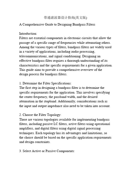
带通滤波器设计指南(英文版)A Comprehensive Guide to Designing Bandpass Filters Introduction:Filters are essential components in electronic circuits that allow the passage of a specific range of frequencies while attenuating others. Among the various types of filters, bandpass filters are widely used in a variety of applications, including audio processing, telecommunications, and signal conditioning. Designing an effective bandpass filter requires a thorough understanding of its characteristics and the specific requirements for a given application. This guide aims to provide a comprehensive overview of the design process for bandpass filters.1. Determine the Filter Specifications:The first step in designing a bandpass filter is to determine the specific requirements for the application. This involves specifying the center frequency, the passband width, and the desired attenuation in the stopband. Additionally, considerations such as the input and output impedance also need to be taken into account.2. Choose the Filter Topology:There are various topologies available for implementing bandpass filters, including passive LC filters, active filters using operational amplifiers, and digital filters using digital signal processing techniques. Each topology has its advantages and limitations, so the choice should be based on the specific application requirements and design constraints.3. Select Active or Passive Components:Based on the chosen filter topology, select the appropriate active or passive components. In passive LC filters, inductors, and capacitors are commonly used, while active filters employ operational amplifiers. The selection of these components should consider factors such as their tolerances, temperature coefficients, and availability.4. Design the Passband and Stopband Characteristics:Designing the passband and stopband characteristics involves determining the required gain in the passband and the attenuation in the stopband. Various design methods such as Butterworth, Chebyshev, and Elliptic filters can be used to achieve the desired characteristics. The choice of the filter type depends on the trade-off between passband flatness and stopband attenuation.5. Calculate Component Values:Once the filter type and the desired characteristics are chosen, calculate the component values using appropriate design equations or software tools. These calculations involve determining the values of resistors, capacitors, and inductors that will achieve the desired gain, cutoff frequencies, and bandwidth. This step requires careful consideration of component tolerances and their impact on the filter performance.6. Prototype and Test:After designing the bandpass filter, it is important to prototype the circuit and test its performance. This involves building the circuit using the calculated component values and measuring its frequency response using an oscilloscope or a spectrum analyzer. Any deviations from the desired characteristics should be analyzed, andadjustments can be made to the component values to improve the filter's performance.7. Consider Practical Limitations:During the design process, it is essential to consider various practical limitations that could affect the filter's performance. Some common limitations include component tolerances, parasitic capacitances and inductances, and the impact of non-ideal op-amp behavior. These practical limitations should be taken into account to ensure the filter achieves its desired performance in real-world conditions.Conclusion:Designing bandpass filters involves a systematic and iterative process that requires a sound understanding of the filter characteristics and the specific application requirements. By following the guidelines provided in this comprehensive guide, engineers can effectively design bandpass filters that meet the required specifications. Regular testing and refining of the filter design are crucial to ensure optimal performance in real-world applications.8. Consider Filter Implementation Considerations: Apart from the filter specifications and the choice of topology, there are additional implementation considerations that designers should keep in mind. These considerations include the power supply requirements, board space constraints, cost limitations, and compatibility with other components in the system. It is important to evaluate the impact of these factors on the overall design and make appropriate trade-offs to meet the desired performance within the given constraints.9. Minimize Noise and Distortion:Bandpass filters can introduce additional noise and distortion to the signal. This is particularly important in applications such as audio processing or high-frequency communication systems where signal integrity is critical. Design techniques such as proper grounding, component selection, and careful layout design can help minimize noise and distortion in the filter circuit. It is crucial to pay attention to the signal path and minimize any potential sources of interference or distortion.10. Consider Temperature and Environmental Effects:The performance of electronic components, including capacitors, inductors, and semiconductors, can vary with temperature. Therefore, it is important to consider the effects of temperature variations on the bandpass filter design. This may involve choosing components with appropriate temperature coefficients, incorporating thermal compensation measures, or conducting thermal simulations to ensure the filter operates within the desired performance range under various temperature conditions. Additionally, if the filter is intended for use in harsh environments, such as high humidity or extreme temperatures, appropriate encapsulation or conformal coating may be needed to protect the components from moisture and other environmental factors.11. Optimize for Efficiency:Efficiency is an important consideration in many applications, especially for battery-powered devices or systems with limited power budgets. Designers should aim to minimize power consumption while still achieving the desired filter performance. This may involve choosing low-power operational amplifiers,optimizing component values for minimum power dissipation, or exploring alternative digital filter implementations that offer better power efficiency.12. Consider Signal-Level Requirements:Bandpass filters are often used in systems where the input signals can vary widely in amplitude. It is important to consider the signal-level requirements, such as the maximum and minimum input signal levels, and ensure that the filter can handle these variations without distortion or clipping. This may involve choosing components with appropriate voltage and current ratings, incorporating amplitude modulation techniques, or implementing automatic gain control (AGC) circuits to maintain a constant output level across a wide range of input signals.13. Consider EMI/EMC Compliance:In many applications, electromagnetic interference (EMI) and electromagnetic compatibility (EMC) compliance are critical for reliable operation and meeting regulatory standards. Bandpass filters can both emit and be susceptible to EMI. Designers should consider shielding techniques, proper grounding, and filtering to minimize the emission and susceptibility of the filter circuit to unwanted electromagnetic radiation or noise. Compliance with EMI/EMC standards should be verified through appropriate testing and measurements.14. Document the Design:It is vital to document the bandpass filter design, including the design specifications, topology, component values, and any design trade-offs or considerations. This documentation will serve as avaluable reference for future modifications, troubleshooting, or replication of the design. Additionally, documenting the design helps in assessing its performance against the desired specifications and provides valuable insights for future design iterations or improvements.15. Continuously Improve and Refine the Design:Designing bandpass filters is an iterative process, and continuous improvement and refinement are crucial to achieving optimal performance. Regular testing, analysis of measurement data, and feedback from real-world applications should drive the improvement process. By closely monitoring the filter's performance and seeking opportunities for enhancement, designers can gradually improve the design over time.Conclusion:Designing bandpass filters involves a systematic approach that takes into account the specific application requirements, the choice of filter topology, and various practical considerations. By following the steps outlined in this comprehensive guide, engineers can design bandpass filters that meet the desired specifications and perform effectively in real-world applications. Consistent testing, refinement, and documentation ensure a robust and reliable design that can be further optimized and improved.。
场地计划英语

IntroductionThe creation of a high-quality, high-standard site is an intricate process that demands meticulous planning, encompassing various aspects such as environmental sustainability, functionality, aesthetics, accessibility, safety, and community integration. This comprehensive site plan proposal presents a multi-faceted approach to achieving these objectives, providing a detailed roadmap for the development of a site that not only meets but exceeds the expectations of stakeholders and end-users alike.1. **Site Analysis and Contextual Integration**The first step in any site planning exercise is a thorough analysis of the existing conditions, including topography, soil types, hydrology, vegetation, and built environment. This information serves as the foundation for designing a site that is harmoniously integrated with its surroundings.a) **Environmental Sensitivity**: The plan should consider the preservation and enhancement of natural features such as waterways, wetlands, and significant trees. Sustainable stormwater management strategies, such as permeable pavements, rain gardens, and bioswales, can be employed to minimize runoff and promote groundwater recharge. Moreover, a robust landscaping plan, incorporating native and drought-resistant species, can enhance biodiversity and reduce maintenance requirements.b) **Contextual Design**: The architectural style, scale, and materials used in the site development should respectfully reflect and complement the surrounding neighborhood or district's character. Historical or cultural elements, if present, should be preserved or creatively interpreted to reinforcea sense of place and continuity.2. **Functional Layout and Spatial Efficiency**The site layout should be optimized for efficient use of space while ensuring smooth circulation and operational functionality.a) **Zoning and Land Use**: The plan should allocate spaces according to their intended functions – residential, commercial, recreational, etc. –considering factors such as noise, privacy, and visual impact. Mixed-use developments, where appropriate, can foster vibrant communities and reduce dependence on automobiles.b) **Circulation and Accessibility**: Pedestrian, bicycle, and vehicular traffic flows should be carefully planned to minimize congestion and ensure safe, convenient access to all areas of the site. Adequate provision of parking facilities, in line with local regulations and demand, is crucial. Universal design principles should be applied to ensure accessibility for individuals with disabilities.c) **Infrastructure and Utilities**: The plan should incorporate efficient and resilient systems for water supply, wastewater management, electricity, telecommunications, and waste disposal. Opportunities for renewable energy generation (e.g., solar panels, geothermal systems) and energy-efficient technologies should be explored.3. **Aesthetics and Urban Design**A visually appealing and cohesive site design contributes significantly to the overall user experience and the project's long-term success.a) **Public Spaces and Amenities**: Well-designed public spaces – parks, plazas, promenades, playgrounds – serve as social anchors, fostering community interaction and promoting well-being. These spaces should be inclusive, adaptable to various activities, and aesthetically pleasing, with thoughtful consideration given to lighting, furniture, and artwork.b) **Building Massing and Orientation**: Building heights, setbacks, and facades should be arranged to create visually interesting streetscapes, maximize daylighting and views, and minimize adverse effects such as wind tunnels or overshadowing. The use of green roofs, terraces, and other vertical landscaping can enhance the site's visual appeal and ecological performance.4. **Sustainability and Resilience**Incorporating sustainable and resilient practices is essential for ensuring the long-term viability and adaptability of the site.a) **Energy Efficiency**: Buildings should be designed to meet or exceed local energy efficiency codes, utilizing passive design strategies, high-performance building envelopes, and energy-efficient systems. Green building certifications, such as LEED or BREEAM, can provide a framework for assessing and improving the site's environmental performance.b) **Water Conservation**: In addition to stormwater management measures mentioned earlier, the plan should promote water-efficient fixtures, appliances, and landscaping practices. Rainwater harvesting and greywater reuse systems can further reduce potable water consumption.c) **Climate Adaptation and Resilience**: Considering potential climate change impacts, such as increased temperatures, sea-level rise, or extreme weather events, the plan should incorporate adaptive measures like elevated structures, flood-resistant materials, shading devices, and heat-island mitigation strategies.5. **Community Engagement and Social Responsibility**Effective community engagement throughout the planning process ensures that the site reflects the needs and aspirations of its users, fostering a sense of ownership and support.a) **Public Participation**: Engage stakeholders through open houses, workshops, surveys, and online platforms to gather input on key design decisions. Regular communication updates can help maintain transparency and trust.b) **Social Equity**: The site should be designed to promote social inclusivity, providing accessible amenities, affordable housing options (where applicable), and safe, welcoming public spaces for people of all ages, abilities, and socio-economic backgrounds.c) **Economic Benefits**: The site plan should aim to generate local economic benefits, such as job creation, business opportunities, and property value appreciation, while considering potential negative impacts like gentrification or displacement.ConclusionThis comprehensive site planning proposal outlines a multi-faceted approach to developing a high-quality, high-standard site that seamlessly integrates environmental sensitivity, functional efficiency, aesthetic appeal, sustainability, and community engagement. By diligently following this approach, we can create a site that not only meets current needs but also adapts and thrives in the face of future challenges, leaving a lasting positive legacy for generations to come.。
The_Operational_Amplifier

total gain. That is, the number A in Eq.(1-2A-1)can be on the order of(属 于同类的,约为) 100,000 or more. (For example, cascading of five transistor amplifiers, each with a gain of 10, would yield this value for A.) A second important factor is that these circuits can be built in such a way that the current flow into each of he inputs is very small. A third important design feature is that the output of the device acts like an ideal voltage source. We now can analyze the particular amplifier circuit given in Fig.1-2A-2 using these characteristics. First we note that the voltage at the positive input,U+, is equal to the source voltage, U U _ .Various currents are defined in part b lf the figure. Applying KVL around the outer loop in Fig.1-2A-2b and remembering tat the output voltage, U o , is measured with respect ground ,we have
CUPT2021试题以及参考中文翻译

CUPT2021试题以及参考中文翻译1. Invent Yourself 自己发明Design a boat that moves only due to the periodical mechanical movements of its internal parts and which only interacts with the environment (air, water) through its stiff hull. Optimise the parameters of your boat for maximum speed.设计一艘只因内部部件的周期性机械运动而移动的船,并且它只通过坚硬的船体与环境(空气、水)相互作用产生移动。
优化你所建的船的参数以达到最大速度。
2.Circling Magnets 旋转磁铁Button magnets with different diameters are attached to each end of a cylindrical battery. When placed on an aluminium foil the object starts to circle. Investigate how the motion depends on relevant parameters.将直径不同的纽扣磁铁贴附到圆柱形电池的两端。
将其放置到铝箔上后,物体会开始旋转。
探究相关参数如何影响该运动。
3.Proximity Sensor 接近传感器A simple passive inductive sensor can detect ferromagnetic objects moving through its magnetic field. Construct such a passive sensor and investigate its characteristics such as sensing range.一个简单的无源感应传感器可以探测到穿过它磁场的铁磁性物体。
- 1、下载文档前请自行甄别文档内容的完整性,平台不提供额外的编辑、内容补充、找答案等附加服务。
- 2、"仅部分预览"的文档,不可在线预览部分如存在完整性等问题,可反馈申请退款(可完整预览的文档不适用该条件!)。
- 3、如文档侵犯您的权益,请联系客服反馈,我们会尽快为您处理(人工客服工作时间:9:00-18:30)。
Design of a 1-V Operational Passive Sigma-DeltaModulatorToru Sai and Yasuhiro Sugimoto*Chuo UniversityDepartment of Electrical, Electronic, and Communication EngineeringTokyo, Japansai@comp.elect.chuo-u.ac.jp, *sugimoto@elect.chuo-u.ac.jpAbstract— The 1-V operation of a passive sigma-delta modulator has been realized. The dc voltage in the signal paths in the second-order switched capacitor filter section was set at 0.2 V so that metal-oxide-semiconductor (MOS) switches in the signal paths would have enough gate-to-source voltage to turn on without using a voltage boosting scheme. The input switch was replaced by a passive resistor to avoid floating. By modifying gain coefficients in the feedback and the input paths, the bias voltage of digital-to-analog converter (DAC) can be set to 1 V and 0 V and MOS switches become easily activated. Moreover, the correlated double sampling (CDS) scheme was adopted to suppress the 1/f noise and offset voltage produced at the input of a comparator. Successful operation from 1-V supply voltage was confirmed by circuit simulation using the 0.18-um complementary MOS (CMOS) process.I.I NTRODUCTIONThe scaling of CMOS devices has accompanied the reduction of supply voltage for large-scale integration (LSI) circuits in the nanometer processing era. In a 32-nm CMOS process, for example, the supply voltage becomes less than 1.0 V [1]. However, it becomes extremely difficult to achieve high performance for analog circuits with this low supply voltage. As the passive sigma-delta modulator (PSDM) [2]-[5] does not need operational amplifiers (Op-amps) or operational transconductance amplifiers (OTAs), in other words, any analog circuitry, it seems to be the way for future analog circuits to take. The main advantage of PSDM is that the filter does not suffer from non-linearity, bandwidth, and power supply introduced by active elements. On the other hand, as the comparator input signal is very small, its input signal may have to be amplified in order to minimize the influence of the comparator 1/f noise and offset voltage. However, this amplifier does not need to be linear, as only the sign of its output signal has to be considered [5]. Although previous study [3] realized 1.5-V operation by using a 0.13-um CMOS process, further reduction of the supply voltage is difficult because of problems such as the floating state in switches [6], the decrease of the signal to noise and distortion ratio (SNDR) due to the offset voltage in differential signal paths and the 1/f noise at the input of a comparator. A hybrid-type combined structure of active and passive filters has been proposed [7] to solve the SNDR issue. However, the supply voltage is still 1.5 V and analog circuits are used in it. Considering use in the nanometer processing era, in this paper we propose circuits to realize 1-V operation and solve noise issues while employing a PSDM.II.O BSTRACLES OF A CHIEVING L OW-V OLTAGEO PERATIONA. Floating SwitchFig. 1 shows the second-order passive filter of a PSDM in which the switched capacitor circuit technique is used without an operational amplifier. Each part in a dashed-line box acts as a resistor and realizes the second-order filter as a whole. All switches consist of MOS transistors. In Fig. 1, the voltage at the in and out terminals is commonly chosen as half the supply voltage, that is, VDD/2. This means the voltage at the in and out terminals becomes 0.5 V when VDD is 1 V. At that point it is very much difficult for a MOS switch to be turned on in a state of low on-resistance with 0.5 V or less of gate-to-source voltage, and the MOS switch becomes a floating switch. Although in the past the gate voltage could easily be boosted to activate a MOS switch, this is no longer the case, because the gate voltage can-not be raised due to the questionable reliability. The maximum gate voltage for a MOS switch should be equal to VDD.Fig. 1. A circuit of a conventional second-order passive filter.B. 1/f Noise at the Input of a ComparatorFig. 2 shows the block diagram of the PSDM. Eq standsfor the quantization noise, G for the comparator gain, Ecomfor noise at the comparator input and H for the transferfunction of the filter [3]. The actual PSDM consists of MOSswitches, capacitors, a comparator and a latch.Fig. 2. Block diagram of a passive sigma-delta modulator.The input signal is modulated by the data sequence of themodulator output in Fig. 2 and has high-frequencycomponents around fs/2, where fs is the clock frequency ofthe modulator. As the filter has no positive voltage gain andattenuates high-frequency signals, the signal at the input of acomparator becomes very small. This means that the Ecom inFig. 2 should be small enough in comparison with the outputsignal from the filter. Therefore, the size of input transistorsof a comparator should be large in order to have small 1/fnoise. However, this deteriorates comparison speed.C. Offset Voltage at the Input of a ComparatorAs the signal that comes out of a filter in Fig. 2 is verysmall, the reference voltage of a comparator should,theoretically, be kept absolutely constant. However, this isimpossible and, in actual circuits, the differential signal isused as the input of a comparator, as shown in Fig. 3. Thereare two filters, xscfp and xscfm, in differential channels.When the offset voltage voff exists in a comparator xcmp, asshown in Fig. 3, voltages becomes vcom+(voff/2) at node‘cp’ and vcom-(voff/2) at node ‘cm’. There is a settlingdifference between those nodes and, as a result, thedistortion deteriorates. It becomes important to reduce thecomparator offset voltage to have a good signal-to-distortionratio.Fig. 3. Comparator offset voltage and its influence.III.T HE R EALIZATION OF THE L OW-V OLTAGE O PERATIONA. Lowering the Signal Path Voltage TechniqueLowering the voltage in the signal path of a filter easilyturns on a MOS switch. Fig. 4 shows the circuit of a newlydesigned filter in a PSDM. In this design, the relationshipamong voltages at terminals ‘a’, ‘vin’ and ‘vbias’ becomes)vbiasvin(b1cra1cra1crvbiasva−+−= (1)If we chose vbias=0.3 V, vin=0.5 V, and cr1a=cr1b, thenva=0.2V, which means the common mode voltage from node‘a’ to node ‘vout’ is biased in low voltage (vcom=0.2 V)throughout. In this situation, switches have enough Vgsvoltage (0.8 V under no signal condition) and, therefore,floating never occurs.Although the voltage at internal nodes is lowered, thevoltage at terminal vin remains VDD/2, because it needs tointerface with the outside of the modulator. As the staticvoltage of the input terminal vin becomes 0.5 V, a MOSswitch cannot have enough gate to source voltage from the 1-V supply voltage. For this reason, the input switch is replacedby a linear resistor Rin [8], as shown in Fig. 4.The need to boost the gate voltage for a MOS switch iscompletely eliminated in this setup.Also it becomes easy to design a comparator by low biasvoltage (vcom=0.2V), because the current source can beinserted at the input of differential PMOS transistors in thecomparator.Fig. 4. A newly designed passive switched capacitor filter.Fig. 5. DAC circuit.B. Optimization of Switch Bias in the DACFig. 5 shows DAC circuit. The voltages ‘vrep’ and ‘vrem’ are conventionally chosen such that ‘vrep-vbias’ becomes equal to vbias-vrem’, that is, 0.6V and 0V, respectively, when vbias=0.3V. This results in entering the floating state for DAC switches. By modifying the input and feedback gain coefficient, the floating switch can be avoided.In Fig. 5, ‘y’ is the feedback data from the modulator output, and φ1 and φ2 are clocks. In synchronizing with φ1, data ‘y’ decides which switch of vrep and vrem becomes on. The φ2 resets the charge stored on cr1b. The timing diagram of DAC control clocks φ1 and φ2 and modulator output signal ‘y’ is shown in Fig. 5. The signal swing of ‘y’ is 1V. The following relationship holds()rem ,rep in bias swing v a2cr a 1cr a 2cr v v 2a 2cr a 1cr a1cr v ++−+=(2)where vswing is the voltage swing at node ‘a’ in Fig. 5 and vrep,rem is the voltage swing of signal ‘y’. By substituting values crla=600 fF, cr1b=200 fF, vbias=0.3 V, vin=0.5 V ±80 mV and vrep,rem=1 V, equation (2) becomesrem ,rep in swing v 25.045.0v 75.0v ++−= (3)The gain scaling of the input signal vin and feedback DAC data vrep,rem is shown in Fig. 6. The scaled DAC feedback signal is subtracted from the scaled input signal and becomes the SPICE simulated waveform shown in Fig. 7. Clock frequency fs is 100 MHz and vin is 0.5 V ±80 mV.Fig. 6. Gain scaling in the input and the feedback loop.Fig. 7. Waveform of node a (Va) in Fig.5.By performing the scaling described above, the voltage of ‘vrep’ in Fig. 5 can be 1 V and that of ‘vrem’ 0 V. As a result, MOS switches that connect to vrep and vrem can be turned on easily because 1 V is used for the gate-to-source voltage of a switch transistor. In Fig. 7, the effective signal swing at node ‘a’ is 0.12 V peak to peak (0.75 times the input signal), and the effective feedback signal swing becomes 0.25 V peak to peak (0.25 times VDD) centered at 0.2 V of dc voltage. The maximum voltage is limited to 0.385 V, and this ensures turning on of a MOS switch in low resistance.C. 1/f Noise Reduction and Offset Voltage Cancellation of a ComparatorAs previously discussed in section II-B, the noise at the input of a comparator greatly affects the overall signal-to-noise ratio (SNR) of the PDSM. Considering comparison speed, the transistor size in the first stage of a comparator should be small. As a result, 1/f noise of a MOS transistor is large, and this limits the SNR of the modulator.In Fig. 8, the 1/f noise voltage v 1/f is assumed to exist at the input of ‘cmpa1’. First, switches sw3, sw4, sw5 and sw6 turn on while sw1 and sw2 turn off. At this time, 1/f noise at inputs of ‘cmpa1’ is sampled across capacitors cp1 plus cp2 by the amount of (Av 1/f )/(1+A), where A is the voltage gain of ‘cmpa1’. Next, sw1 and sw2 become on and sw3, sw4, sw5 and sw6 turn off, allowing signals from filters applied to ‘cmpa1’ through capacitors cp1 and cp2. Low-frequency noise such as 1/f noise does not change its voltage during the short period of time when a high-frequency clock signal controls those switches. Therefore, 1/f noise at input terminals ‘ainmx’ and ‘ainpx’ of ‘cmpa1’ becomes (Av 1/fNEW )/2(1+A) and {v 1/fNEW -(Av 1/fOLD )/2(1+A)}, where v 1/fNEW and v 1/fOLD are the current and memorized 1/f noises, respectively, and approximately v 1/fNEW of 1/f noise appears at the output of ‘cmpa1’ while the signal is A times amplified. This means the 1/f noise is reduced relative to the signal. The offset voltage is suppressed in the same manner. In this way, 1/f noise and offset voltage are reduced.Fig. 8. A comparator and a latch with CDS.IV. C IRCUIT D ESIGN OF A S IGMA -D ELTA M ODULATOR Rin, cr1a and cr1b in Fig. 5 are set at 1/3k Ω, 600 fF and 200 fF, respectively. The minimum capacitor value throughout the circuit is 200 fF, and the total capacitor value is 95 pF. The DAC switches are CMOS switches, while the other switches are n-type MOS (NMOS) switches. The size of the NMOS is 32 um/0.18 um (W/L), and that of thePMOS is 64 um/0.18 um (W/L). The frequency bandwidth of this sigma-delta modulator is 100 kHz. The first pole and the second pole of this second-order filter are 80 kHz and 340 kHz, respectively, and the zero is 7.5 MHz. Circuits are differentially configured, and the common-mode feedback is applied to each stage of a comparator. To have small 1/f noise and to interface with 0.2 V of dc output voltage of the previous stage, we set the input differential pair of the first to fourth stages of a comparator to use PMOS transistors.V. S IMULATION R ESULTSThe designed circuit is SPICE simulated using device parameters of the 0.18-um CMOS process. The supply voltage is 1.0 V, and the clock frequency, fs, is 100 MHz. A. The Effect of Lowering the Signal Path VoltageFig. 9 is the fast Fourier transform (FFT) results of two different designs with the input signal frequency of 30 kHz and amplitude of ±1/2FS. One is the conventional design, where the signal path voltage of a filter is 0.5 V. The other is the newly designed setup in which the signal path voltage is lowered to 0.2 V. It is clearly seen in Fig. 9 that the newly designed setup is suitable to 1-V operation.Fig.9. Comparison of FFT result.B. CDS EffectsThe time-domain 1/f noise source is applied to the input of a comparator to determine the influence on noise and distortion. In this simulation, the voltage gain and the bandwidth of the first-stage comparator are 24 dB and 150 MHz, respectively, while the voltage gain and bandwidth of the whole comparator are 118 dB and 80 MHz. Taking 1/f noise parameters of a transistor into account, which are based on the actual noise measurements of a transistor, the Ecom value is estimated to be 32 uVrms.When the input signal with a frequency of 100 kHz and an amplitude of 0.32 V peak to peak (±1/2FS) is applied in a differential manner, the FFT plot of the output pulse-width modulation (PWM) waveform is obtained, as shown in Fig. 10. The noise and distortion level of the curve with CDS is about 8 dB lower than those of the curve without CDS. Considering the frequency bandwidth 100 kHz, the SNR becomes 76dB in the case with CDS even with time-domain 1/f noise source. Table 1 compares the performance of thisdesign with previous designs. Only our work realizes 1-V operation of a PSDM without deteriorating the performance.Fig.10. FFT plot of the output PWM waveform.Table 1. Performance comparison of various designs.VI. C ONCLUSIONThe realization possibility of a 1-V operational passive sigma-delta modulator has been examined. By lowering the voltage of signal paths in a filter, by using a linear resistor for the input, by modifying the gain in the feedback data path and by introducing CDS and offset canceling techniques for a comparator, 1-V operation of a PSDM becomes possible. We confirmed this via circuit simulation using device parameters of the 0.18-um CMOS process. R EFERENCES[1] International Technology Roadmap for Semiconductors:2008[2] Feng Chen and Bosco Leung, “A 0.25mW 13b Passive ΣΔ Modulatorfor 10MHz IF input,” ISSCC Dig. Tech. Paper, pp. 58-59, February 1995.[3] Feng Chen, Srinath Ramaswamy, and Bertan Bakkaloglu, “A 1.5V1mA 80dB Passive ΣΔADC in 0.13um Digital CMOS Process,” ISSCC Dig. Tech. Papers, pp. 54-55, February 2003.[4] Toru Choi, Tatsuya Sakamoto, and Yasuhiro Sugimoto, “A Study toRealize a 1-V Operational Passive Σ-Δ Modulator by Using a 90nm CMOS Process,” IEICE Trans. Electronics, vol. E90-C, pp. 1304-1306, June 2007.[5] Philippe BENABES, Richard KIELBASA, “Passive Sigma-Deltaconverters design,” IEEE Instrument and Measurement Technology Conference, pp. 469-474, May, 2002.[6] Mustafa Keskin, Un-Ku Moon, and Gabor C. Temes, “A 1-V 10-MHzClock-Rate 13-Bit CMOS ΔΣ Modulator Using Unity-Gain-Reset Opams,” IEEE J. Solid-State Circuit, vol.37, pp. 817-824, July 2002. [7] Tongyu Song, Zhiheng Cao, and Shouli Yan, “A 2.7mW 2-MHzContinuous-Time ΣΔ Modulator With a Hybrid Active-Passive Loop Filter,” IEEE J. Solid-State Circuit, vol.43, pp. 330-341, February 2008. [8] Min Gyu Kim, Gil-Cho Ahn, Pavan Kumar Hanumolu, Sang-HyeonLee, Sang-Ho Kim, Seung-Bin You, Jae-Whui Kim, Gabor C. Tems, and Un-Ku Moon, “A 0.9V 92dB Double-Sampled Switched-RC Delta-Sigma Audio ADC,” IEEE J. Solid-State Circuit ., vol.43, pp. 1195-1206, May 2008.。