RMDVB1-9PS1P中文资料
多功能电力仪表用户手册.pdf_1694086039.4589636说明书

多功能电力仪表用户手册本手册适用于以下型号的产品PD194E-9HYPD194Z-9HY感谢您选择江苏斯菲尔电气股份有限公司研发的多功能电力仪表,为了方便您安全、正确、高效的使用本装置,请仔细阅读本说明书并在使用时务必注意以下几点。
注意CAUTION:◆该装置必须由专业人员进行安装与检修◆在对该装置进行任何内部或外部操作前、必须隔离输入信号和电源◆始终使用合适的电压检测装置来确定仪表各部位有无电压◆提供给该装置的电参数需在额定范围内下述情况会导致装置损坏或装置工作的异常:◆辅助电源电压超范围◆配电系统频率超范围◆电流或电压输入极性不正确◆带电拔插通信插头◆未按要求连接端子连线本手册可以在本公司的主页上下载到最新版本,同时也提供一些相应的测试软件下载。
如果您需要备份纸质用户手册可以向本公司的技术服务部门申请。
(具体公司网址、联系电话等见封底)目录一、产品简介 (1)1.1引用标准 (1)1.2产品概述 (1)二、技术参数 (2)三、安装与接线 (3)3.1仪表尺寸 (3)3.2安装方式 (4)3.3接线端子功能说明 (5)3.4输入信号线连接 (6)四、菜单显示与编程 (7)4.1面板说明 (7)4.2菜单介绍与操作 (8)4.3编程操作方法 (19)五、功能模块 (24)5.1通信 (24)5.2电能脉冲输出 (29)5.3开关量输入 (30)5.4继电器输出 (30)5.5模拟量输出 (33)六、常见问题及解决办法 (37)6.1关于通信 (37)6.2关于U I P Q等测量不准确 (37)6.3关于电能走字不准确 (37)6.4仪表不亮 (38)6.5仪表不响应任何操作 (38)6.6其它异常情况 (38)附录1MODBUS-RTU通信地址信息表 (39)一、产品简介1.1引用标准引用国家标准GB/T17215.322-2008静止式有功电能表(0.2S级和0.5S级)GB/T17215.323-2008静止式无功电能表(2级和3级)GB/T17626-2006电磁兼容试验和测量技术相应国际标准IEC62053-22:2003电量测量设备(交流)-特殊要求-第22部分:静态电度表(0.2S和0.5S)IEC62053-23:2003电量测量设备(交流)-特殊要求-第23部分:静态无功表(2级和3级)IEC61010-1:2001测量、控制以及实验室用电气设备的安全要求-第1部分:一般要求IEC61000-2-11电磁兼容性(EMC)-第2-11部分IEC60068-2-30环境测试-第2-30部分1.2产品概述多功能电力仪表可测量各种常用电力参数、有无功电能、谐波含量和最大最小值记录,并具有数字通信、继电器输出、开关量输入、电能脉冲输出和模拟量输出等功能。
NORTE北电中文手册

LD 10PBX 电话机管理提示和响应-LD 10标号提示响应注释1 REQ 请求CHG 修改现有的数据块CPY n 从指定的分机数据块自动拷贝或生成1至32个新的分机数据块对Option 11各模式无效,版本12和其后的软件。
END 退出覆盖程序MOV 将数据块从一个TN移到另一个。
对Option 11各模式无效。
NEW X 增加新的数据块NEW后是一个1-255的数值,以生成此数目的接连的电话机数据块OUT X 取消数据块OUT后是一个1-255的数值,以取消此数目的接连的电话机数据块2 TYPE 数据块类型500500/2500电话机数据块500 M7Option 11的500/2500模式电话机数据块CARD 自动话机移位(ASR)的500/2500卡板块CARDSLT 单线电话机用户线卡板(版本19和其后的软件)OOSSLT20停止运行单线终端单元3 MODL71-127 模式号码,对Option 11模式话机提示。
4 CFTN 1 s c u 从TN拷贝,在REQ=CPY时提示。
c u7用于Option11,用这个TN作为新话机的样板。
5 SFMT 对拷贝命令选用以下一种格式,在CLS=AGTA时,提示POS。
D N输入项可长达4位,配备DNXP软件包150则长达7位TNDN 人工选择TN,DN和ACD电话机的ACD座席IDTN,DN和POS提示-n-次,如在CPY命令中所规定。
TN l s c u 新话机的TNDN xxxx 新话机的DNPOS xxxx ACD座席IDTN 新DN和ACD电话机的ACD座席ID是由系统提供的,对您提示要求开始的DN,ACD座席ID和每一个TN。
TN提示n次,如在CPY命令中所规定。
DN xxxx 新话机的DNPOS xxxx ACD座席IDTN l s c u 新话机的TNDN 新TN都是由系统提供的,对您提示要求开始的TN和每一个DN以及ACD电话机的ACD座席ID。
pa8000plc中文手册【word版】9p

CASE INT1 OF
1, 5:BOOL1 := TRUE;
BOOL3 := FALSE;
2:BOOL2 := FALSE;
BOOL3 := TRUE;
ELSE
BOOL1 := NOT BOOL1;
BOOL2 := BOOL1 OR BOOL2;
END_CASE;
循环指令(FOR)
<步长Step size>}DO
用
当程序发生错误时,你可以设置断点。当处理发生中断时,你就可以及时的在断点处检查所有工程变量的值。工作在单步方式(singlestep)下,可以检验程序的逻辑错误。
你可以强制输入或输出变量的值。使用流控制(flowcontrol)可以知道哪些程序段已经执行。采样轨迹(SamplingTrace)显示变量在长时间的变化过程曲线。
整个工程可以以文本文件的形式导出。
总而言之PLC-1131-3 DS对于PLC编程是一种完善和方便的工具。
2.2PLC-1131-3 DS基本概念
此节包括一些重要的概念帮助你熟悉PLC-1131-3 DS
2.2.1
工程
一个工程包括了
程序结构单元POUs
数据类型data types
资源resources
返回指令
返回指令用来结束函数调用,当条件满足时返回主程序
条件指令
使用IF指令检验是否满足条件,当条件满足时执行相应的的指令
语法:
IF<布尔表达式_1>THEN
<IF_指令>
{ELSIF<布尔表达式_2>THEN
<ELSIF_指令1>
.
.
ELSIF<布尔表达式_n>THEN
proteus英文对照表

AD芯片-----TECHWELL TW6805A仿真软件里的AD0809有问题,用0808代替定时/计数器的使用方法:CLK:计数和测频状态时,数字波的输入端。
(counter enable)CE:计数使能端;通过属性设置高还是低有效。
无效暂停计数RST:复位端(RESET),可设上升沿(Low-High)或者下降沿(High-Low)有效。
4种工作方式:通过属性Operating Mode 来选择。
Default : 缺省方式,计数器方式。
Time(secs):100S定时方式,由CE和RST控制暂停和重新开始。
Time(hms):10小时定时方式,同上。
Frequency: 测频方式,CE和RST有效时,显示CLK端数字波频率Count:计数方式。
+++++++++++++++++++++++++++++++++++++++++++++++++++++++++++++ 常用元件列表:POT-HG 可调电位器7SEG-MPX8-CC-BLUE 8位数码管COMPIM 串口SW- 开关7SEG-BCD 含译码驱动的数显Speaker 扬声器2N5771和2N5772,15V对管300MARES , CAP,BUTTON 按钮开关KEYPAD-PHONE 3*4电话键盘KEYPAD-SMALLCALC 4*4计算器键盘KEYPAD-CALCULATOR 4*6计算器键盘PGA 128*128液晶++++++++元件库详细分类1.analog ics 模拟集成器件8个子类:amplifier 放大器comparators 比较器display drivers 显示驱动器filters 滤波器miscellaneous 混杂器件regulators 三端稳压器timers 555定时器voltage references 参考电压2,capacitors CAP电容,23个分类别animated 可显示充放电电荷电容audio grade axial 音响专用电容axial lead polypropene 径向轴引线聚丙烯电容axial lead polystyrene 径向轴引线聚苯乙烯电容ceramic disc 陶瓷圆片电容decoupling disc 解耦圆片电容high temp radial 高温径向电容high temp axial electrolytic高温径向电解电容metallised polyester film 金属聚酯膜电容metallised polypropene 金属聚丙烯电容metallised polypropene film 金属聚丙烯膜电容miniture electrolytic 微型电解电容multilayer metallised polyester film 多层金属聚酯膜电容mylar film 聚酯薄膜电容nickel barrier 镍栅电容non polarised 无极性电容polyester layer 聚酯层电容radial electrolytic 径向电解电容resin dipped 树脂蚀刻电容tantalum bead 钽珠电容variable 可变电容vx a xial electrolytic VX 轴电解电容3,CMOS 4000 series 4000系列数字电路adders 加法器buffers & drivers 缓冲和驱动器comparators 比较器counters 计数器decoders 译码器encoders 编码器flip-flops & latches 触发器和锁存器frequency dividers & tiner 分频和定时器gates & inverters 门电路和反相器memory 存储器misc.logic 混杂逻辑电路mutiplexers 数据选择器multivibrators 多谐振荡器phase-locked loops(PLL) 锁相环registers 寄存器signal switcher 信号开关4,connectors 接头;8个分类:audio 音频接头D-type D型接头DIL 双排插座header blocks 插头miscellaneous 各种接头PCB transfer PCB 传输接头SIL 单盘插座ribbon cable 蛇皮电缆terminal blocks 接线端子台5,data converters 数据转换器:4个分类:A/D converters 模数转换器D/A converters 数模转换器sample & hold 采样保持器temperature sensors 温度传感器6,debugging tools 调试工具数据:3个类别:breakpoint triggers 断点触发器logic probes 逻辑输出探针logic timuli 逻辑状态输入7,diodes 二极管;8个分类:bridge rectifiers 整流桥generic 普通二极管rectifiers 整流二极管schottky 肖特基二极管switching 开关二极管tunnel 隧道二极管varicap 稳压二极管8,inductors 电感:3个类别:generic 普通电感SMT inductors 表面安装技术电感transformers 变压器9,laplace primitives 拉普拉斯模型:7个类别:1st order 一阶模型2nd order 二阶模型controllers 控制器non-linear 非线性模型operators 算子poles/zeros 极点/零点symbols 符号10,memory ICs 存储器芯片:7个分类:dynamic RAM 动态数据存储器EEPROM 电可擦出程序存储器EPROM 可擦出程序存储器I2C memories I2C总线存储器memory cards 存储卡SPI Memories SPI总线存储器static RAM 静态数据存储器11,microprocessor ICs 微处理器:13个分类:12,modelling primitivvves 建模源:9个分类:13,operational amplifiers 运算放大器:7个分类:dual 双运放ideal 理想运放macromodel 大量使用的运放octal 8运放quad 4运放single 单运放triple 三运放14,optoelectronics 光电器件:11个分类:7-segment displays 7段显示alphanumeric LCDs 液晶数码显示bargraph displays 条形显示dot matrix displays 点阵显示graphical LCDs 液晶图形显示lamps 灯LCD controllers 液晶控制器LCD controllers 液晶面板显示LEDs 发光二极管optocouplers 光电耦合serial LCDs 串行液晶显示15,resistors 电阻:11个分类:0.6w metal film 0.6w金属膜电阻10 watt wirewound 10w绕线电阻2w metal film 2w 金属膜电阻3 watt wirewound 3w 绕线电阻7 watt wirewound 7w 绕线电阻generix 普通电阻high voltage 高压电阻NTC 负温度系数热敏电阻resistor packs 排阻variable 滑动变阻器varisitors 可变电阻参考试验中采用的可变电阻是:POT-HG16,simulator primitives 仿真源:3个类别:flip-flops 触发器gates 门电路sources 电源17,switches and relays 开关和继电器:4个类别:key pads 键盘relays 普通继电器relays(specific) 专用继电器switches 开关18,switching devices 开关器件:4个分类:DIACs 两端交流开关generic 普通开关元件SCRs 可控硅TRIACs 三端双向可控硅19,真空管:20,传感器:2个分类:pressure 压力传感器temperature 温度传感器21,晶体管:8个分类:bipolar 双极型晶体管generic 普通晶体管(错误)IGBT 绝缘栅双极晶体管JFET 结型场效应管MOSFET 金属氧化物场效应管RF power LDMOS 射频功率LDMOS管RF power VDMOS 射频功率VDMOS管unijunction 单结晶体管Electromechanical 电机MOTOR AC 交流电机MOTOR SERVO 伺服电机双相步进电机motor-bistepper(Bipolar Stepper Motor),四相步进电机motor-stepper(unipolar stepper motor)驱动电路,用ULN2003可以,proteus中推荐的L298和L6201(电子元件-步进电机中有L298资料)+++++++++++++++++++++++++++++++++++++++++++++++++++++++++++++++++++++ 步进电机,可以用MTD2003,UN2916等专用芯片Proteus中图形液晶模块驱动芯片一览表LM3228 LM3229 LM3267 LM3283LM3287 LM4228 LM4265 LM4267LM4283 LM4287 PG12864F PG24064FPGA PGAAGM1232G EW12A03GL Y HDM32GS12-B HDM32GS12Y-BHDG12864F-1 HDS12864F-3 HDG12864L-4 HDG12864L-6NOKIA7110 TGGFSB TG13650FEYAMPIRE128x64 LGM12641BS1RPROTEUS原理图元器件库详细说明Device.lib 单双向可控硅、包括电阻、电容、二极管、三极管和PCB的连接器符号、ACTIVE.LIB 包括虚拟仪器和有源器件、拨动开关、键盘、可调电位器和开关、DIODE.LIB 包括二极管和整流桥、稳压管、变容二极管、大功率二极管、高速二极管、可控硅、DISPLAY.LIB 包括LCD、LED、LED阵列BIPOLAR.LIB 包括三极管FET.LIB 包括场效应管ASIMMDLS.LIB 包括模拟元器件AS 稳压二极管、全桥、74系列、及其他。
海信各机型维修BOM 管理代码 机芯方案 屏型汇总

型号编码型号名称管理代码1TD26C9TCN0B TLM26V86K0 1TD4045TCN0B TLM40V86PK1000 1TD4043TCN0B TLM40V68PK0 1TD4283PCN0B TLM42V68PK1000 1TD5503TCN0T TLM55T08GP1100 1TD4283PCN0B TLM42V68PK1002 1TD42D3MCN0B TLM42V86PK1000 1TD42A3TCN0B TLM42V67PK1000 1TD42A3TCN0B TLM42V67PK1001 1TD42A3TCN0B TLM42V67PK1012 1TD42A3TCN0B TLM42V67PK1003 1TD42A3TCN0B TLM42V67PK1004 1TD42A3TCN0B TLM42V67PK1015 1TD42A3TCN0B TLM42V67PK1016 1TD4715TCN0B TLM47V67PK1000 1TD4715TCN0B TLM47V67PK1001 1TD4715TCN0B TLM47V67PK1002 1TD4715TCN0B TLM47V67PK1003 1TD4715TCN0B TLM47V67PK1004 1TD4715TCN0B TLM47V67PK1005 1TD5208PCN0B TLM52V67PK1000 1TD5208PCN0B TLM52V67PK1011 1TD5208PCN0B TLM52V67PK1002 1TD32K4TCN0B TLM32V88PK1010 1TD32K4TCN0B TLM32V88PK1011 1TD4722TCN0B TLM47V88PK0 1TD4722TCN0B TLM47V88PK1001 1TD42A2TCN0B TLM42V88GP1100 1TD42A2TCN0B TLM42V88GP1001 1TD4719PCN0B TLM47V88GP1100 1TD5501PCN0B TLM55V88GP1000 1TD5504TCN1T TLM55T69GP1100 1TD5504TCN1T TLM55T69GP1101 1TD2249MCN0B TLM22V661 1TD2249MCN0B TLM22V662 1TD2246MCN1B TLM22V88X1 1TD2246MCN1B TLM22V88X2 1TD2402TCN0B TLM24V86P0 1TD2402TCN0B TLM24V86P1 1TD2402TCN0B TLM24V86P2 1TD26E5MCN0R LED26T291000 1TD2257TCN0R LED22T29P1000 1TD1975TCN0R LED19T291000 1TD32P3MCN0B LED32T281000 1TD42E2PCN0B TLD42V88GPQ0 1TD42E2PCN0B TLD42V88GPQ1 1TD4290PCN0B TLM42V68PKA1000 1TD4290PCN0B TLM42V68PKA1001 1TD4283PCN0B TLM42V68PK1003 1TD42E8TCN0B TLM42V86PKV0 1TD3769PCN0B TLM37V88P1000 1TD3779TCN0B TLM37V86K01TD32M5TCN0B TLM32V86K1123 1TD26C0TCN0B TLM26V88K1100 1TD26C0TCN0B TLM26V88K1101 1TD26C0TCN0B TLM26V88K1102 1TD26C9TCN0B TLM26V86K1101 1TD26C9TCN0B TLM26V86K1102 1TD2401TCN1B TLM24V88PK0 1TD2401TCN1B TLM24V88PK1 1TD2649TCN3B TLM26E29下乡100 1TD26C9TCN0B TLM26V86K100 1TD32K4TCN0B TLM32V88PK1022 1TD32G8TCN0B TLM32V881001 1TD1967MCN0B TLM19V6613 1TD1965TCN0B TLM19V88X13 1TD2249MCN0B TLM22V663 1TD2407MCN0B TLM24V68P1 1TD2246MCN0B TLM22V88X3 1TD2401TCN1B TLM24V88PK2 1TD2214PCN3B TLM22V681102 1TD2247PCN1B TLM22V68X2 1TD26D3MCN0B LED26T281111 1TD26E5MCN0R LED26T29111 1TD2649TCN2B TLM26E291100 1TD26C2TCN0B TLM26E29X1100 1TD26C2TCN0B TLM26E29X502 1TD2693TCN2B TLM26V6817 1TD2693TCN2B TLM26V688 1TD2693TCN2B TLM26V681019 1TD26B9TCN1B TLM26V68X17 1TD26C9TCN0B TLM26V86K113 1TD26C9TCN0B TLM26V86K1200 1TD32P3MCN0B LED32T281000 1TD32L9TCN0B TLM32E29X1007 1TD32Q5TCN0B TLM32V67K11 1TD32Q5TCN0B TLM32V67K1133 1TD32G3TCN0B TLM32V68C1011 1TD32G3TCN0B TLM32V68C151D1TD32G3TCN0B TLM32V68C103E1TD32L8MCN0B TLM32V68CX1017 1TD32M5TCN0B TLM32V86K1112 1TD32M5TCN0B TLM32V86K1100 1TD32M5TCN0B TLM32V86K1114 1TD32K4TCN0B TLM32V88PK1022 1TD32P5PCN0B TLD32V88Q1000 1TD3777TCN0B TLM37E29X1117 1TD3768PCN0B TLM37V687 1TD3779TCN0B TLM37V86K1102 1TD3779TCN0B TLM37V86K1100 1TD3779TCN0B TLM37V86K1111 1TD3779TCN0B TLM37V86K21TD4045TCN0B TLM40V86PK1000 1TD4283PCN0B TLM42V68PK1002 1TD4283PCN0B TLM42V68PK1004 1TD4290PCN0B TLM42V68PKA1000 1TD4290PCN0B TLM42V68PKA1001 1TD4290PCN0B TLM42V68PKA1002 1TD42D3MCN0B TLM42V86PK1000 1TD42E8TCN0B TLM42V86PKV1 1TD42E8TCN0B TLM42V86PKV2 1TD42A2TCN0B TLM42V88GP2100 1TD42A2TCN0B TLM42V88GP3000 1TD42F5PCN0B TLM42V88GPA1 1TD42F5PCN0B TLM42V88GPA1011 1TD42E2PCN0B TLD42V88GPQ1001 1TD42D7PCN0A LED42T18GP1101 1TD4612TCN0B TLM46V86PK100 1TD4715TCN0B TLM47V67PK1005 1TD4722TCN0B TLM47V88PK1012 1TD4722TCN0B TLM47V88PK1000 1TD4722TCN0B TLM47V88PK1003 1TD4722TCN0B TLM47V88PK1004 1TD5208PCN0B TLM52V67PK1002 1TD5504TCN1T TLM55T69GP1101 1TD5504TCN1T TLM55T69GP1102 1TD5501PCN0B TLM55V88GP1001 1TD1967MCN0B TLM19V664 1TD2405TCN0R LED24T29P11 1TD2693TCN2B TLM26V68000A1TE3201TCN0B LED32T28KV11 1TD32M5TCN0B TLM32V86K1115 1TD3781TCN0B TLM37V66K1102 1TD26B9TCN1B TLM26V68X000A1TD3786TCN0B TLM37V89KV11 1TD4052MCN0B TLM40V66PK1111 1TD42D2TCN0B TLM42V66PK1111 1TD4283PCN0B TLM42V68PK1015 1TD4616TCN0B TLM46V89PKV100 1TD2257TCN1R LED22T29P11 1TD2413TCN0B TLM24V66P1100 1TD2402TCN0B TLM24V86P1100 1TD32M3TCN0B TLM32V661002 1TD32G3TCN0B TLM32V68C11 1TD32G3TCN0B TLM32V68C151C1TD3768TCN0B TLM37V682016 1TD42D2TCN0B TLM42V66PK1102 1TD4719PCN0B TLM47V88GP2100 1TD4722TCN0B TLM47V88PK1025 1TD5509PCN0A LED55T18GP1111 1TD5511MCN0R LED55T29GP122 1TD5511MCN0R LED55T29GP1331TD32P9TCN0R LED32T29P1022 1TD4043TCN0B TLM40V68PK1020 1TD42E6MCN0R LED42T29GP111 1TD4739MCN1R LED47T29GP1101 1TD32S6TCN0B TLM32V78K1 1TD42F7TCN0B TLM42V78PK11 1TD4052MCN0B TLM40V66PK1120 1TD42E6MCN0R LED42T29GP113 1TD42E6MCN0R LED42T29GP122 1TD5217MCN0B TLM52V78PKN1 1TD26G0TCN0R LED26T29P12 1TD26D3MCN0B LED26T281003 1TD26D3MCN0B LED26T281024 1TD2413TCN1B TLM24V66P1110 1TD2416TCN0B TLM24V78PK10 1TD26F9TCN0B LED26K1611 1TD26G0TCN1R LED26T29P23 1TD32P9TCN1R LED32T29P1023 1TE1901MCN0B LED19K160 1TE2409MCN0B LED24K010 1TE2407MCN0B LED24K11P0 1TE2407MCN0B LED24K11P11 1TE2401MCN0B LED24K16P0 1TE2401TCN0B LED24K16P11 1TE2607MCN0B LED26K010 1TE2609MCN0B LED26K01A0 1TE2605TCN0B LED26K110 1TD26F9TCN0B LED26K160 1TD26D3MCN0B LED26T280 1TE3216MCN0B LED32K010 1TE3216MCN0B LED32K011 1TE3209TCN0B LED32K110 1TE3209TCN0B LED32K111 1TE3209TCN0B LED32K112 1TE3209TCN0B LED32K113 1TE3209TCN2B LED32K117 1TE3202TCN0B LED32K160 1TE3202TCN0B LED32K1612 1TE3202TCN0B LED32K161001 1TE3203PCN0B LED32T26GP0 1TE3201TCN0B LED32T28KV22 1TE3213TCN0R LED32T29KV0 1TD32P9TCN0R LED32T29P0 1TD32P9TCN1R LED32T29P1134 1TE3706MCN0B LED37K010 1TE3705PCN0B LED37K110 1TE3705PCN0B LED37K111 1TE3703MCN0B LED37K160 1TE3703MCN0B LED37K161 1TE3701TCN0B LED37T28KV01TE4012PCN0B LED40K11P0 1TE4012PCN0B LED40K11P1 1TE4005PCN0B LED40K16P0 1TE4005PCN0B LED40K16P1 1TE4001TCN1B LED40T28PKV1001 1TE4214MCN0B LED42K01P0 1TE4205PCN0B LED42K11P0 1TE4205PCN0B LED42K11P11 1TE4205PCN0B LED42K11P12 1TE4205PCN0B LED42K11P1103 1TE4203PCN0B LED42K16P0 1TE4203PCN0B LED42K16P12 1TE4217MCN0B LED42K16X3D0 1TD42E6MCN1R LED42T29GP114 1TE4209MCN0B LED42XT39G3D0 1TE4209MCN0B LED42XT39G3D1001 1TE4612MCN0B LED46K01P0 1TE4611PCN0B LED46K11P0 1TE4611PCN0B LED46K11P11 1TE4611PCN0B LED46K11P2 1TE4604PCN0B LED46K16P0 1TE4604PCN0B LED46K16P1 1TE4614PCN0B LED46K16PN0 1TE4615MCN0B LED46K16X3D0 1TE4601TCN1B LED46T28PKV1033 1TE4608MCN0B LED46XT39G3D0 1TD4733MCN0A LED47T18GP0 1TD4733MCN0A LED47T18GP1101 1TD4739MCN0R LED47T29GP0 1TE5502PCN0B LED55T28GPN0 1TE5502PCN0B LED55T28GPN1100 1TE5502PCN1B LED55T28GPN1111 1TD5511MCN0R LED55T29GP0 1TD5511MCN1R LED55T29GP11 1TE5501PCN0T LED55T29GP3D0 1TE5506MCN0B LED55XT39G3D0 1TD42E2PCN4B TLD42V88GPQ3012 1TD42E2PCN1B TLD42V88GPQ1012 1TD1986MCN0B TLM19G660 1TD1967MCN1B TLM19V664 1TD2246MCN0B TLM22V88X0 1TD2407MCN0B TLM24V68P0 1TD2407MCN0B TLM24V68P10 1TD2416TCN0B TLM24V78PK0 1TD26G7TCN0B TLM26E010 1TD26C1TCN0B TLM26V660 1TD26C1TCN0B TLM26V661002 1TD26F4MCN0B TLM26V760 1TD26F5TCN0B TLM26V78K0 1TD26F5TCN0B TLM26V78K1 1TD26F5TCN1B TLM26V78K12 1TD26C9TCN1B TLM26V86K1214 1TD32V4TCN0B TLM32E0101TD32G4TCN0B TLM32V68A0 1TD32G4TCN0B TLM32V68A11 1TD32G4TCN0B TLM32V68A3 1TD32T1MCN0B TLM32V760 1TD32S6TCN0B TLM32V78K0 1TD32S6TCN0B TLM32V78K13 1TD32S6TCN0B TLM32V78K24 1TD32S6TCN0B TLM32V78K15 1TD32S6TCN1B TLM32V78K26 1TD32S6TCN1B TLM32V78K527 1TD32V1MCN0B TLM32V78X3D0 1TD32U3MCN0B TLM32V79KV0 1TD32U3MCN0B TLM32V79KV11 1TD3797TCN0B TLM37E010 1TD3781TCN0B TLM37V66K0 1TD3781TCN0B TLM37V66K1111 1TD3768PCN0B TLM37V6820 1TD3768PCN0B TLM37V681 1TD3768PCN0B TLM37V6812 1TD3768PCN0B TLM37V6813 1TD3768PCN0B TLM37V684 1TD3791TCN0B TLM37V760 1TD3791TCN1B TLM37V761 1TD3791TCN1B TLM37V7612 1TD3799MCN0B TLM37V78X3D0 1TD3796MCN0B TLM37V79KV0 1TD3788TCN0B TLM37V860 1TD3786TCN0B TLM37V89KV0 1TD4068PCN0B TLM40E010 1TD4052MCN0B TLM40V66PK0 1TD4052MCN0B TLM40V66PK1222 1TD4043TCN0B TLM40V68PK1120 1TD4043TCN0B TLM40V68PK1222 1TD4062TCN0B TLM40V78PK0 1TD4062TCN0B TLM40V78PK10 1TD4062TCN0B TLM40V78PK111 1TD4066MCN0B TLM40V79PKV0 1TD42D2TCN0B TLM42V66PK0 1TD42D2TCN0B TLM42V66PK2113 1TD42F9TCN0B TLM42V76P0 1TD42F9TCN1B TLM42V76P512 1TD42F7TCN0B TLM42V78PK22 1TD42F7TCN0B TLM42V78PK13 1TD42H3PCN0B TLM42V79D310 1TD42G7MCN0B TLM42V79PKV0 1TD42G7MCN0B TLM42V79PKV11 1TD4622MCN0B TLM46V66PK0 1TD4622MCN0B TLM46V66PK113 1TD4622MCN0B TLM46V66PK224 1TD4622MCN0B TLM46V66PK5211TD42J0TCN0B TLM42E010 1TD2405TCN1R LED24T29P0 1TE2615MCN0B LED26K01AG2 1TE2609MCN0B LED26K01A111 1TE2615MCN0B LED26K01AG0 1TE3236MCN0B LED32K01G2 1TE3236MCN0B LED32K01G0 1TE3236MCN0B LED32K01G1 1TE3209TCN2B LED32K118 1TE3235TCN0B LED32K11G0 1TE3706MCN0B LED37K011 1TE3708PCN0B LED37T39AK0 1TE4016MCN0B LED40K01P1 1TE4214MCN0B LED42K01P1 1TE4205PCN0B LED42K11P1214 1TE4205PCN0B LED42K11P1112 1TD42E6MCN0R LED42T29GP0 1TE4212MCN0B LED42T29PR3D0 1TE2422TCN0B LED24K11PG11 1TD2431TCN0B LED24K16PG11 1TE2607MCN1B LED26K0111 1TE2615MCN0B LED26K01AG111 1TE2605TCN0B LED26K1111 1TE2605TCN1B LED26K11122 1TE2613TCN0B LED26K11G0 1TE2613TCN0B LED26K11G11 1TE3216MCN1B LED32K01103 1TE3236MCN0B LED32K01G103 1TE3209TCN3B LED32K119 1TE3209TCN2B LED32K11114 1TE3235TCN0B LED32K11G1 1TE3235TCN0B LED32K11G206 1TE3235TCN0B LED32K11G2 1TE3235TCN0B LED32K11G3 1TE3235TCN0B LED32K11G7 1TE3235TCN0B LED32K11G8 1TE3237TCN0B LED32K16G1015 1TE3237TCN0B LED32K16G0 1TE3237TCN0B LED32K16G12 1TE3237TCN0B LED32K16G1001 1TE3233TCN0B LED32K210 1TE3234TCN0B LED32K260 1TE3220MCN0R LED32T29X3D0 1TE3244MCN0R LED32T29X3DG0 1TE3232PCN0B LED32T39AK0 1TE3245PCN0B LED32T39AKG0 1TE3707MCN0B LED37K01Z0 1TE3709MCN0B LED37K01G0 1TE3709MCN0B LED37K01G1 1TE3705PCN1B LED37K1121TE3711PCN0B LED37K11G1 1TE3703MCN0B LED37K161001 1TE3710MCN0B LED37K16G0 1TE3710MCN0B LED37K16G1 1TE3712MCN0B LED37T29X3D0 1TE3713PCN0B LED37T39AKG0 1TE4029MCN0B LED40K01PG0 1TE4030PCN0B LED40K11PG0 1TE4030PCN0B LED40K11PG1 1TE4005PCN0B LED40K16P1001 1TE4031PCN0B LED40K16PG0 1TE4031PCN0B LED40K16PG1 1TE4027PCN0B LED40T39AK0 1TE4040PCN0B LED40T39AKG0 1TE4040PCN0B LED40T39AKG11 1TE4214MCN2B LED42K01P102 1TE4214MCN1B LED42K01P3 1TE4228MCN0B LED42K01PG0 1TE4228MCN1B LED42K01PG102 1TE4205PCN1B LED42K11P1115 1TE4203PCN0B LED42K16P1203 1TE4226TCN0B LED42K210 1TE4227TCN0B LED42K260 1TE4227TCN0B LED42K2611 1TE4212MCN0B LED42T29PR3D1101 1TE4229MCN0B LED42T39AK0 1TE4612MCN0B LED46K01P1 1TE4612MCN1B LED46K01P12 1TE4611PCN2B LED46K11P1123 1TE4604PCN1B LED46K16P1112 1TE4628TCN0B LED46K210 1TE4627TCN0B LED46K260 1TE4630MCN0B LED46T39AK0 1TE4616PCN0B LED46T39D410 1TE4616PCNCB LED46T39D41111 1TE4608MCN0B LED46XT39G3D1111 1TE4608MCN0B LED46XT39G3D1112 1TE4623MCN0B LED46XT68G3D0 1TE4704MCN0R LED47T29PR3D0 1TE4704MCN0R LED47T29PR3D1101 1TE5506MCN0B LED55XT39G3D1112 1TE5515MCN0B LED55XT68G3D0 1TE5513MCN0M LED55XT69G3D0 1TE6001MCN0M LED60XT69G3D0 1TD1967MCN1B TLM19V661004 1TD26G7TCN0B TLM26E0111 1TD26H0MCN0B TLM26H780 1TD26H2TCN0B TLM26V66C0 1TD26H4TCN0B TLM26V66CG11 1TD26F4MCN1B TLM26V761 1TD32V2MCN0B TLM32H780 1TD32Y3MCN0B TLM32V66C0 1TD32S6TCN3B TLM32V78K181TD3798MCN0B TLM37H780 1TD37A1TCN0B TLM37V66C0 1TD37A1TCN1B TLM37V66C11 1TD3793MCN0B TLM37V78K0 1TD4069TCN0B TLM40V66C0 1TD4062TCN0B TLM40V78PK12 1TD42J0TCN0B TLM42E0111 1TD42J6MCN0B TLM42H780 1TD42J3TCN0B TLM42V66C0 1TD42J3TCN0B TLM42V66C11 1TD42F9TCN2B TLM42V76P3 1TD42F7TCN0B TLM42V78PK0 1TD42J4MCN0B TLM42V78X3D0 1TD4632TCN0B TLM46V66C0 1TD4632TCN3B TLM46V66C11 1TD4747MCN0B TLM47V78X3D0 1TD4745MCN0B TLM47V79PKV0 1TD5523MCN0B TLM55V89PKN0 1TE5511MCN0R LED55T29SG3D1 1TD42J0TCN1B TLM42E0112 1TE3209TCN2B LED32K11206 1TE4217MCN0B LED42K16X3D1 1TE4615MCN0B LED46K16X3D1 1TD4068PCN1B TLM40E011 1TE5506MCN0B LED55XT39G3D1111 1TE2409MCN1B LED24K011 1TE2426MCN0B LED24K18G11 1TE2605TCN2B LED26K11134 1TE3209TCN3B LED32K11206 1TE3202TCN1B LED32K161046 1TE3232PCN0B LED32T39AK22 1TE3706MCN1B LED37K013 1TE3705PCN1B LED37K113 1TE3703MCN1B LED37K161002 1TE4214MCN1B LED42K01P4 1TE4214MCN5B LED42K01P102 1TE4217MCN0B LED42K16X3D112 1TE4612MCN1B LED46K01P134 1TE4611PCN2B LED46K11P1246 1TE4627TCN0B LED46K2611 1TD26G7TCN1B TLM26E0112 1TD26H0MCN0B TLM26H7811 1TD26H2TCN1B TLM26V66C11 1TD3797TCN1B TLM37E0120 1TD42J0TCN6B TLM42E01123 1TE3258TCNCB LED32K280 1TE3259TCNCB LED32T360 1TE3257MCNCB LED32T36X3D0 1TE4053MCNCB LED40K16X3D0 1TE4239TCNCB LED42K28P0 1FC0801SCN0B M2800 1TE2426MCN0B LED24K18G0 1TE2437TCNCB LED24K31601TE2441TCNCB LED24K3100 1TE2607MCNNB LED26K01122 1TE2616MCN0B LED26K18G0 1TE2616MCN0B LED26K18G11 1TE2616MCN0B LED26K18G22 1TE2625TCNCB LED26K3100 1TE2625TCNCB LED26K31011 1TE2627TCNBB LED26H3100 1TE2628TCNCB LED26K3000 1TE3216MCNNB LED32K0125 1TE3216MCNNB LED32K0126 1TE3264TCNCB LED32K3110 1TE3265TCNCB LED32XT39G3D0 1TE3298TCNCB LED32K10X3D0 1TE3271MCNCB LED32K3160 1TE3269TCNCB LED32K316X3D0 1TE3275TCNCB LED32K3000 1TE3276TCNBB LED32H3100 1TE3706MCNNB LED37K012 1TE3711PCN0B LED37K11G2 1TE3711PCN0B LED37K11G3 1TE3715MCNFB LED37T36X3D0 1TE3716TCNCB LED37T360 1TE3901TCNCB LED39K310X3D0 1TE3902TCNCB LED39K316X3D0 1TE3902TCNCB LED39K316X3D11 1TE4027PCN0B LED40T39AK11 1TE4052MCNCB LED40XT39G3D0 1TE4052MCNCB LED40XT39G3D11 1TE4053MCNCB LED40K16X3D11 1TE4205PCNNB LED42K11P1226 1TE4214MCNNB LED42K01P217 1TE4243TCNCB LED42K3110 1TE4246TCNCB LED42K316X3D0 1TE4248TCNCB LED42K310X3D0 1TE4248TCNCB LED42K310X3D11 1TE4301MCNCB LED43K510G3D0 1TE4615MCN0B LED46K16X3D1012 1TE4647MCNCB LED46XT710G3D0 1TE4651TCNCB LED46K3110 1TE4705MCNCB LED47T36X3D0 1TE5002PCNCB LED50K316X3D0 1TE5002PCNCB LED50K316X3D1 1TE5519MCNCB LED55T36X3D0 1TE5520MCNCB LED55XT710G3D0 1TE5521MCNCB LED55K510G3D0 1TE5522MCNCB LED55T36GP1 1TE5522MCNCB LED55T36GP0机芯方案MT82226M68FQCMST6M68FQ6M68FQC6M68FQC6M68FQC6M68FQC6M68FQC6M68FQC6M68FQC6M68FQC6M68FQC6M68FQC6M68FQC6M68FQC6M68FQC6M68FQC6M68FQC6M68FQC6M68FQC6M68FQC6M68FQC6M68FQC6M68FQC6M68FQC6M68FQ6M68FQC6M68FQC6M68FQC6M68FQC6M68FQC6M68FQC6M68FQCMST721MST721MST721MST721MST6E16JSMST6E16JSMST6E16JSMT8222_1080PMT8222_1080PMT8222_1080PMT8222_1080PMST6M68FQC+ST7101 MST6M68FQC+ST7101 6M68FQC6M68FQC6M6FQC6M68FQC+RTD10736E16JS+7266HMT8222MT8222_1080P6E16JS+7266HMT8222_1080PMT8222_1080PMT8222_1080PMT8222_1080PMT8222_1080PMT8222_1080PMT8222_1080PMT8222_1080PMT8222(720P)MT8222(720P)MST9U19EMT8222_1080P6M68FQC6E16JS+7266HMST721MST721MST721MST740KUMST721MT8222(720P)机芯:由MST9U19B更改为MST740不变MT8222(1080P)/机芯不变,功能升级为支持1080P,端子数量和位置MT8222(1080P)由MST9U19E更改为MST740由MST9U19E更改为MST740MST9U19EMST721MST721由MST721DU方案更换为HX6217-E方案MST721MT8222更改前:MTK8222 720P方案主板,更改后:MTK8222 1080P方案降成更改为MT8222的1080p主板,主芯片不变,更改外围电路由原来:MST9U19A变化为:MST9U19EMT8222机芯:有变化,机芯重新排版。
RMD-L 电机用户手册V1.2
RMD-L电机驱动控制协议V1.2免责声明感谢您购买光毓机电RMD-L系列电机驱动系统。
在使用之前,请仔细阅读本声明,一旦使用,即被视为对本声明全部内容的认可和接受。
请严格遵守手册、产品说明和相关的法律法规、政策、准则安装和使用该产品。
在使用产品过程中,用户承诺对自己的行为及因此而产生的所有后果负责。
因用户不当使用、安装、改装造成的任何损失,光毓机电将不承担法律责任。
光毓机电是光毓机电(上海)有限公司及其关联公司的商标。
本文出现的产品名称、品牌等,均为其所属公司的商标或注册商标。
本产品及手册为光毓机电版权所有。
未经许可,不得以任何形式复制翻印。
关于免责声明的最终解释权,归光毓机电所有。
简介RMD-L电机驱动系统采用32位高性能MCU、高带宽运放、低内阻扁平封装MOSFET,结合FOC控制技术,搭配特别设计的高性能无刷电机,专为高精度、高响应、大扭矩应用打造。
电机与驱动的一体化设计,方便用户系统整合。
驱动集成高精度绝对值编码器,配合成熟的闭环控制算法,大幅提高了位置、速度和力矩控制的精度和响应。
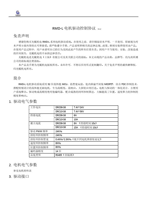
1.驱动电气参数2.电机电气参数参见电机特性表3.驱动接口4.总线特性总线接口芯片:MAX485波特率:9600, 19200, 57600, 115200(默认)数据位:8奇偶校验:无停止位:15.设定上位机连接电机驱动和上位机之间可以通过USB转RS485模块连接。
电机驱动出厂时默认波特率为115200,默认ID由拨码开关设定,一般为1,因此,上位机连接前的设置如下(其中COM根据实际情况选择),点击CONNECT按钮后,连接设备。
基础设定,在Setting页面中,点击Read按钮读取电机信息拨码开关与ID对应关系如下表:Driver BaudrateShutdown Time:设置电机的关闭时间。
在该时间内没有收到控制命令,电机会关闭;设置为0时,电机始终不会关闭。
Angle:角度环控制参数。
Kp和Ki修改角度环的PI参数,Max Angle用于限制电机的最大转动角度,例如设置为3600时,电机的最大转动角度为±3600°,即正反10圈。
L6599中文版
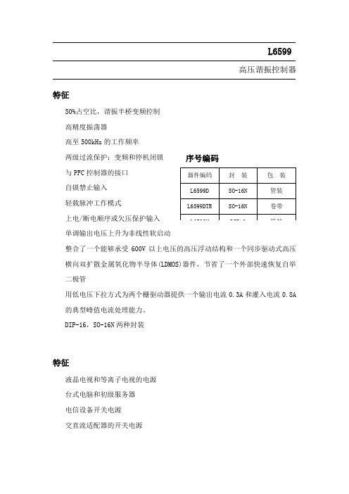
L6599高压谐振控制器特征50%占空比,谐振半桥变频控制 高精度振荡器高至500kHz 的工作频率 两级过流保护:变频和停机闭锁 与PFC 控制器的接口 自锁禁止输入 轻载脉冲工作模式上电/断电顺序或欠压保护输入 单调输出电压上升为非线性软启动整合了一个能够承受600V 以上电压的高压浮动结构和一个同步驱动式高压横向双扩散金属氧化物半导体(LDMOS)器件,节省了一个外部快速恢复自举二极管用低电压下拉方式为两个栅驱动器提供一个输出电流0.3A 和灌入电流0.8A 的典型峰值电流处理能力。
DIP-16,SO-16N 两种封装特征液晶电视和等离子电视的电源 台式电脑和初级服务器 电信设备开关电源 交直流适配器的开关电源序号编码器件编码 封 装 包 装 L6599D SO-16N 管装 L6599DTR SO-16N 卷带 L6599NDIP16管装框图目录1 驱动描述 . . . . . . . . . . . . . . . . . . . . . . . . . . . . . . . . . . . . . . . . . . . . . . . . . .42 引脚设置 . . . . . . . . . . . . . . . . . . . . . . . . . . . . . . . . . . . . . . . . . . . . . . . . . .5引脚排列 . . . . . . . . . . . . . . . . . . . . . . . . . . . . . . . . . . . . . . . . . . . . . . . . . . . .5引脚功能说明 . . . . . . . . . . . . . . . . . . . . . . . . . . . . . . . . . . . . . . . . . . . . . . . . 53 典型系统框图 . . . . . . . . . . . . . . . . . . . . . . . . . . . . . . . . . . . . . . . . . . . . . . 74 电气数据 . . . . . . . . . . . . . . . . . . . . . . . . . . . . . . . . . . . . . . . . . . . . . . . . . . 7极限参数 . . . . . . . . . . . . . . . . . . . . . . . . . . . . . . . . . . . . . . . . . . . . . . . . . . . . . .7热相关数据 . . . . . . . . . . . . . . . . . . . . . . . . . . . . . . . . . . . . . . . . . . . . . . . . . . . . .85 电气参数 . . . . . . . . . . . . . . . . . . . . . . . . . . . . . . . . . . . . . . . . . . . . . . . . . . . 96 典型的电气性能 . . . . . . . . . . . . . . . . . . . . . . . . . . . . . . . . . . . . . . . . . . . . . .127 应用资料 . . . . . . . . . . . . . . . . . . . . . . . . . . . . . . . . . . . . . . . . . . . . . . . . . . . 15振荡器 . . . . . . . . . . . . . . . . . . . . . . . . . . . . . . . . . . . . . . . . . . . . . . . . . . . . . . .16工作在空载或非常轻的负载状态 . . . . . . . . . . . . . . . . . . . . . . . . . . . . . . . . . . .18软启动 . . . . . . . . . . . . . . . . . . . . . . . . . . . . . . . . . . . . . . . . . . . . . . . . . . . . . . . .21电流检测,过流保护和过载保护 . . . . . . . . . . . . . . . . . . . . . . . . . . . . . . . . . 23闭锁关机 . . . . . . . . . . . . . . . . . . . . . . . . . . . . . . . . . . . . . . . . . . . . . . . . . . . . . .26LINE检测功能 . . . . . . . . . . . . . . . . . . . . . . . . . . . . . . . . . . . . . . . . . . . . . . . . . .27自举部分 . . . . . . . . . . . . . . . . . . . . . . . . . . . . . . . . . . . . . . . . . . . . . . . . . . . .28应用实例 . . . . . . . . . . . . . . . . . . . . . . . . . . . . . . . . . . . . . . . . . . . . . . . . . . . . .298 封装外形尺寸 . . . . . . . . . . . . . . . . . . . . . . . . . . . . . . . . . . . . . . . . . . . . . . . . .9 修订记录 . . . . . . . . . . . . . . . . . . . . . . . . . . . . . . . . . . . . . . . . . . . . . . . . . . . .1 驱动描述L6599是一个用于谐振半桥拓扑电路的精确的双端控制器。
RMDVB1-9PL001P中文资料
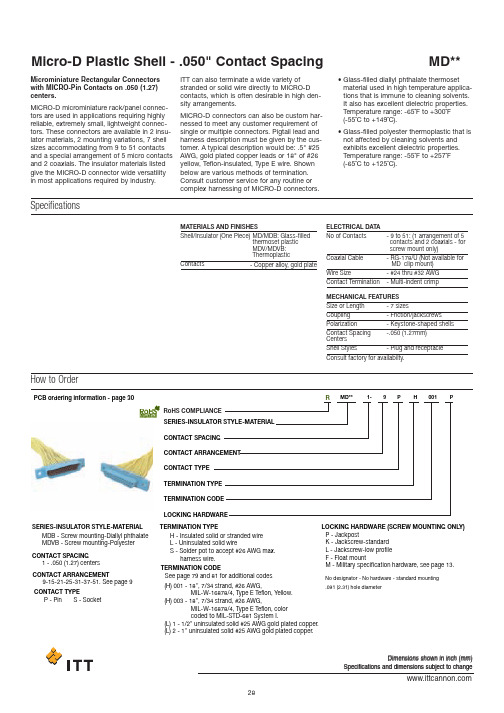
PCB ordering information - page 30SERIES-INSULATOR STYLE-MATERIAL SERIES-INSULATOR STYLE-MATERIALMDB - Screw mounting-Diallyl phthalate MDVB - Screw mounting-Polyester H -Insulated solid or stranded wire L -Uninsulated solid wireS -Solder pot to accept #26 AWG max.harness wire.No designator - No hardware - standard mounting .091 (2.31) hole diameterP -JackpostK -Jackscrew-standard L -Jackscrew-low profile F -Float mountM -Military specification hardware, see page 13.1-.050 (1.27) centers9-15-21-25-31-37-51. See page 9P -Pin S - SocketCONTACT SPACIN GCONTACT ARRAN G EMENTCONTACT TYPECONTACT SPACIN G CONTACT ARRAN G EMENT CONTACT TYPE TERMINATION TYPE TERMINATION TYPELOC K IN G H AR DW ARE (SCRE W MOUNTIN GONLY )TERMINATION CO D E LOC K IN G H AR DW AREM D** 1-9P H 001P(H) 001 - 18",7/34strand, #26 AWG, MIL-W-16878/4,T ype E T eflon, Y ellow.(H) 003 - 18",7/34strand, #26 AWG, MIL-W-16878/4,T ype E T eflon, color coded to MIL-S T D-681System I.(L) 1 - 1/2"uninsulated solid #25 AWG gold plated copper.(L) 2 - 1"uninsulated solid #25 AWG gold plated copper.TERMINATION CO D ERo H S COMPLIANCERSee page 79 and 81for additional codesDimensions shown in inch (mm)Specifications and dimensions subject to changeHow to OrderMicrominiature Rectangular Connectors with MICRO-Pin Contacts on .050 (1.27)centers.MICRO-D microminiature rack/panel connec-tors are used in applications requiring highly reliable, extremely small, lightweight connec-tors. These connectors are available in 2 insu-lator materials, 2 mounting variations, 7 shell sizes accommodating from 9 to 51 contacts and a special arrangement of 5 micro contacts and 2 coaxials. The insulator materials listed give the MICRO-D connector wide versatility in most applications required by industry.ITT can also terminate a wide variety of stranded or solid wire directly to MICRO-D contacts, which is often desirable in high den-sity arrangements.MICRO-D connectors can also be custom har-nessed to meet any customer requirement of single or multiple connectors. Pigtail lead and harness description must be given by the cus-tomer. A typical description would be: .5" #25AWG, gold plated copper leads or 18" of #26yellow, Teflon-insulated, Type E wire. Shown below are various methods of termination.Consult customer service for any routine or complex harnessing of MICRO-D connectors.•Glass-filled diallyl phthalate thermoset material used in high temperature applica-tions that is immune to cleaning solvents.It also has excellent dielectric properties.Temperature range: -65˚F to +300˚F (-55˚C to +149˚C).•Glass-filled polyester thermoplastic that is not affected by cleaning solvents and exhibits excellent dielectric properties.Temperature range: -55˚F to +257˚F (-65˚C to +125˚C).SpecificationsMATERIALS AND FINISHESShell/Insulator (One Piece)MD/MDB: Glass-filledthermoset plastic MDV/MDVB: Thermoplastic ELECTRICAL DATA MECHANICAL FEATURES No of ContactsSize or Length Coupling PolarizationContact Spacing Centers Shell StylesConsult factory for availabilty.Coaxial CableWire SizeContact Termination -9to 51: (1 arrangement of 5 contacts and 2 coaxials - for screw mount only)-7sizes-Friction/jackscrews-Keystone-shaped shells -.050 (1.27mm)-Plug and receptacle-RG-178/U (Not available for MD clip mount)-#24 thru #32 AWG -Multi-indent crimp-Copper alloy, gold plateContactsDimensions shown in inch (mm)Specifications and dimensions subject to changeStandard Wire Termination CodesCavity #1 black*The following termination codes are listed for your information. For additional codes please refer to Appendix on page 79 and 81. All wire lengths are minimum.#26 A WG per MIL-W-16878 Type E Teflon ,stranded.H arness Typ e (H)L ength 3(76.2)6(152.4)8(203.2)10(254.0)12(304.8)18 (457.2)20(508.0)24(609.6)30(762.0)36(914.4)48(1219.2)72(1828.8)120(3048.0)H020H019H026H029H028H001H038H009H010H011H013H017H042H027H016H034H025H002H003H023H004H005H006H048H046H041L61L 56L 57L 39L 58L 1L 14L2L 7L6L 16L 10.125(3.18).150 (3.81).190(4.83).250 (6.35).375(9.52).500 (12.70).750 (19.05)1.000 (25.40)1.500 (38.10)2.000 (50.80)2.500 (63.50)3.000 (76.20)All Y ell o w Co l o r Cod e d*T erminati o n Cod eL ength #25A WG G old P lated CopperS o li d U ninsulate d Typ e (L)With Screw Mounting Holes (Conforms to MIL-DTL-83513)MDB.110(2.79)MAX..154(3.91)(5.08)MAX.Solder PotSolder PotGlass-filled Diallyl Phthalate Plastic InsulatorMDVBGlass-filled Polyester Plastic InsulatorRPart Number by Shell Size Add lead type and length, see Part Number Explanation.Weight given is with 1/2", uninsulated solid #25 AWG gold plated copper pigtails.*****AMax.B Max.C Max.D Max.E Max.F ±.005Avg.Weight***±5% (oz.)±5% (gm.)MDB1-9S**MDB1-15P**MDB1-15S**MDB1-21P**MDB1-21S**MDB1-25P**MDB1-25S**MDB1-31P**MDB1-31S**MDB1-37P**MDB1-37S**MDB1-51P**MDB1-51S**MDVB1-9S**MDVB1-15p**MDVB1-15S**MDVB1-21P**MDVB1-21S**MDVB1-25P**MDVB1-25S**MDVB1-31P**MDVB1-31S**MDVB1-37P**MDVB1-37S**MDVB1-51P**MDVB1-51S**.788 (20.02).788 (20.02).938 (23.82)1.088 (27.64)1.088 (27.64)1.188 (30.18)1.188 (30.18)1.338 (33.98)1.338 (33.98)1.488 (37.80)1.488 (37.80)1.438 (36.52)1.438 (36.52).292 (7.42).380 (9.65).442 (11.23).592 (15.04).680 (17.27).692 (17.58).780 (19.81).842 (21.39).930 (23.62).992 (25.20)1.080 (27.43).942 (23.93)1.030 (26.16).408 (10.36).408 (10.36).588 (14.17).708 (17.98).708 (17.98).808 (20.56).808 (20.56).958 (24.33).958 (24.33)1.108 (28.14)1.108 (28.14)1.058 (26.87)1.058 (26.87).173 (4.39).173 (4.39).173 (4.39).173 (4.39).173 (4.39).173 (4.39).173 (4.39).173 (4.39).173 (4.39).173 (4.39).173 (4.39).220 (5.59).220 (5.59).218 (5.54).218 (5.54).218 (5.54).218 (5.54).218 (5.54).218 (5.54).218 (5.54).218 (5.54).218 (5.54).218 (5.54).218 (5.54).260 (6.60).260 (6.60).565 (14.35).565 (14.35).715 (18.16).865 (21.97).865 (21.97).965 (24.51).965 (24.51)1.115 (28.32)1.115 (38.32)1.265 (32.13)1.265 (32.13)1.215 (30.86)1.215 (30.86).026 (0.73).025 (0.70).038 (1.10).053 (1.50).050 (1.40).063 (1.80).056 (1.60).080 (2.30).073 (2.10).086 (2.45).076 (2.15).109 (3.10).093 (2.64)Dimensions shown in inch (mm)Specifications and dimensions subject to changeMD*B-PCB connectors use standard MD*B all plastic shells and are designed for use with flex circuitry, printed circuit and multi-layer boards. They are easily mounted and soldered and provide high density/high reliability in board-to-board and board-to-cable applica-tions. While being similar to the MDM-PCB connectors, the MD*B-PCB connectors are all plastic, extremely small, and lightweight yet rugged enough for use in the most demanding applications.MD*B-PCB connectors are available inseven shell sizes with 9 to 51 contacts in the popular 90°narrow profile PCB termination,with a variety of tail lengths for varying boardthickness.How to OrderSERIESCONTACT ARRANGEMENT CONTACT TYPE CTERMINATION TYPE THARDWAREHTERMINATION TAIL LENGTH TMODIFICATION CODES C(Consult Factory)MMD*B--37S CBR ** * *L39RoHS COMPLIANCE RJackpost mounting for use with locking hard-ware is also available.If the connectors shown in the catalog do not meet the requirements of your applica-tions, a special shape, size or layout using the basic all plastic shell can be made avail-able. For further technical and applications information, contact customer service.CONNECTOR SERIES MDVB, MDBCONNECTOR ARRANGEMENT9, 15, 21, 25, 31, 51CONTACT TYPES =Socket P =PinTERMINATION TYPECBR = 90°Narrow Profile PCB Terminations HARDWAREP =JackpostM7 = Jackposts, M635135-07No Letter = Less HardwareTERMINATION TAIL LENGTH CODESNONE –.109 (2.77) ±0.15 (0.38) Standard L61– .125 (3.18)L66– .150 (3.81)L57– .190 (4.83)L39–.250 (6.35)L58– .375 (9.52)Dimensions shown in inch (mm)Specifications and dimensions subject to changeCBR Series (90˚ Mounting Narrow Profile)TYP ..186 (4.72) PLUG 9-15-21-25 VIEW*FOR 31: 1.085 (27.56) MAX. FOR 37: 1.185 (30.10) MAX. FOR 51: 1.225 (31.12) MAX.I A. TYPPCB Termination Arrangements (Viewed from bottom of connector, on PCB solder side.)Indentification number shown for plug connector, use reverse order for socket connector..083.020.0209Contacts15 Contacts21 Contacts 25Contacts51 Contacts37 Contacts31 ContactsAll Termination Configurations .100 (2.54) x .100 (2.54) Grid Pattern, Offset .050 (1.27)*For jackpost locking add letter "P" or "M7".NOTE: Standard lead termination is #24 AWG, solid copper, solder or tin dipped.Part Number By Shell Size MD*B-9PCBR*MD*B-9SCBR*MD*B-15PCBR*MD*B-21PCBR*MD*B-21SCBR*MD*B-25PCBR*MD*B-25SCBR*MD*B-31PCBR*MD*B-31SCBR*MD*B-37PCBR*MD*B-37SCBR MD*B-51PCBR*MD*B-51SCBR.788 (20.01).938 (23.82)1.088 (27.63)1.088 (27.63)1.188 (30.17)1.188 (30.17)1.338 (33.98)1.338 (33.98)1.488 (37.79)1.488 (37.79)1.438 (36.52)1.438 (36.52).565 (14.35).715 (18.16).865 (21.97).865 (21.97).965 (24.51).965 (24.51)1.115 (28.32)1.115 (28.32)1.265 (32.13)1.265 (32.13)1.215 (30.86)1.215 (30.86).292 (7.42).525 (13.34).592 (15.04).675 (17.14).692 (17.58).775 (19.68).842 (21.39).925 (23.50).994 (25.25)1.075 (27.30).942 (23.93)1.026 (26.06).218 (5.54).218 (5.54).218 (5.54).218 (5.54).218 (5.54).218 (5.54).218 (5.54).218 (5.54).218 (5.54).218 (5.54).258 (6.55).258 (6.55).134 (3.40).218 (5.54).134 (3.40).218 (5.54).134 (3.40).218 (5.54).134 (3.40).218 (5.54).134 (3.40).218 (5.54).177 (4.50).258 (6.55).420 (10.67).420 (10.67).420 (10.67).420 (10.67).420 (10.67).420 (10.67).420 (10.67).420 (10.67).520 (13.21).520 (13.21).550 (13.97).550 (13.97).250 (6.35).250 (6.35).250 (6.35).250 (6.35).250 (6.35).250 (6.35).250 (6.35).250 (6.35).250 (6.35).250 (6.35).300 (7.62).300 (7.62).230 (5.84).130 (3.30).130 (3.30).130 (3.30).130 (3.30).130 (3.30).130 (3.30).130 (3.30).130 (3.30).130 (3.30).150 (3.81).150 (3.81)A Max.B±.005 (0.13)G±.010 (0.25)H±.010 (0.25)C Max.D Max.E Max.F Max.Dimensions shown in inch (mm)MDB Coaxial Series with Screw Mounting HolesMDB connectors with two coaxial and five MICRO-PIN TM /MICROSOCKET TM contacts. Crimp-type coaxial contacts accommodate RG-178/U cables. A plastic insertion/extraction tool is supplied with each connec-tor assembly having removable coaxial assembly.How to Order - MDB CoaxialSERIESMDB1-7C2****SHKSERIESMicro-D CoaxialNo Letter - Coaxial assemblyinstalled and nonremovable RO - coaxial assembly ordered serparatelyRA - Coaxial shipped assembled but uninstalled See Standard Wire TerminationConsult customer serviceNo letter - No hardware*Not available with removalbe coax cable type connectors RO and RA.standard mounting. 091 (2.31) hole diameter F -FloatK -Jackscrew (standard)L -Jackscrew (low profile)P -JackpostCode on page 29. Coaxial cable will beRG-178U unless otherwise specified; length will be same as wire modification.P -Pin S -Socket L -Uninsulated, solid wireH -Insulated, solid or stranded S -Solder pot*1-.050 (1.27) centers...................7 (2)SIGNAL CONTACT SPACING TOTAL CONTACT CAVITIES NUMBER OF COAXIALS SIGNAL CONTACT SPACING TOTAL CONTACT CAVITIES NUMBER OF COAXIALS COAXIAL TYPECOAXIAL TYPESIGNAL CONTACT TYPE SIGNAL CONTACT TYPESIGNAL CONTACT LEAD TYPE SIGNAL CONTACT LEAD TYPESIGNAL CONTACT LEAD LENGTH SIGNAL CONTACT LEAD LENGTH MODIFICATIONHARDWAREMODIFICATION HARDWARERoHS COMPLIANCE RHow to Order - Coaxial Cable AssembliesSERIESMDCCS** * *COAXIAL CABLE CONTACT TYPE CONTACT TYPE COAXIAL CABLE TYPECOAXIAL CABLE TYPE COAXIAL CABLE LENGTHCOAXIAL CABLE LENGTHSERIES MDP -Pin(used with socket side connection)S -Socket(used with pin type connection)See Standard Wire TerminationCodes on page 29. Coaxial cable will be RG-178U unless otherwise specified; length will be the same as wire modfication.1-RG178/UCOAXIAL CABLE CCRoHS COMPLIANCE RDimensions shown in inch (mm)Specifications and dimensions subject to changeDimension - MDB Coaxial SeriesPlugReceptacle(See page 9 for layouts)Part Numberby Shell SizeMDB1-7C2P*MDB1-7C2S*.510 (12.95).602 (15.29)* Add lead type and length, see Part Number Explanation.** Weight given is with 7 inch (177.80) insulated leads, #26 AWG silver plated copper pigtails and RG178/U coaxials..204 (5.18).185 (4.70).298 (7.57).279 (7.09).782 (19.86).782 (19.86).395 (10.03).375 (9.52).510 (12.95).540 (13.72).290 (8.30).273 (7.80)A Ma x.B Ma x.C Ma x.E Ma x.E 1Ma x.D +_.005 (0.13)Av g .W eight**(oz)+_5% (gm .)+_5%TWO MTG. HOLES RO AND RA COAXESRO AND RA COAXESMounting Hardware Views (Sizes 9-51)This hardware supplied unassembled.Screw Lock Assembly90˚ Angle Mounting BracketDescriptionScrew Lock Assembly Jackpost Kit322-9500-000 320-9505-000015-9516-000 .100 (2.54) .122 (3.10) .257(6.53).215(5.46)015-9516-000 Mounting Bracket, 90˚ Angle- MD*1for 9 thru 37 Shell Sizes MD*1for 51 Shell SizeNOTES: Screw lock assembly (322-9500-000) can be used for front front mounting. Jackpost kit(320-9505-000) consists of 2 assemblies, shipped unassembled.Part Number ±.005 (0.13)Max.*NOTE: Torque value is 4.0 in/lbs max. REF. ONLY_.003_0.08)FACEFACECONNECTOR HEX HEAD -Jackscrew - (L) Low ProfileJackscrew - (K) StandardThis hardware is factory installed.Shown here is a cutaway view of the float mount for the MD connector.The basic shell dimensions are the same for the float mount and the screw mounting hole configurations. View shown is for standard float mount front panel mounting. Reverse mounting is available on request.*NOTE: Torque values are as follows: Low Profile Jackscrew (L)-2.5 in/lbs Standard Jackscrew (K)-2.5 in/lbsDimensions shown in inch (mm)Specifications and dimensions subject to changeMounting Hardware to Military Specification (Sizes 9 - 51) PER MIL-DTL-83513/5This hardware supplied unassembled.Jackscrew - (L) Low profile *.062 (1.57)HEX. (REF.).092 (2.34) DIA.Allen headPlug and Receptacle Low and High Profile Slotted HeadJackpost AssemblyDescriptionSlotted Head Jackscrew Assy Low ProfileSlotted Head Jackscrew Assy High Profile Allen Head Jackscrew Assy Low Profile Allen Head Jackscrew Assy High Profile Jackpost Assy-05-06-02-03-07M5M6M2M3M7320-9508-025320-9508-027320-9508-026320-9508-028320-9505-033M83513/5Mode Code Part Number ThreadJackpost Bushing (For Rear Panel Mounting)MATING FACE.126 (3.20).125 (3.18)DIA.TYP .+.005 (0.13)3/32 (2.4)1/16 (1.6)3/64 (1.2)1/32 (0.8).092/.087 (2.34/2.21).061/.056 (2.34/1.42).047/.042 (1.19/1.07).030/.025 (0.76/0.64)320-9505-007320-9505-006320-9505-005320-9505-0049152125313751.379 ( 9.63).529 (13.44).679 (17.25).779 (19.79).929 (23.60)1.079 (27.41)1.029 (26.14).219 (5.56).219 (5.56).219 (5.56).219 (5.56).219 (5.56).219 (5.56).261 (6.63).565 (14.35).715 (18.16).865 (21.97).965 (24.51)1.115 (28.32)1.265 (32.13)1.215 (30.86)*2Jackposts, 2nuts, 2washers .Panel Thickness A Dim.Jackpost Kit Number*A+.004 (0.10)-.000 (0.00)Shell SizePlug and Receptacle DimensionsB +.004 (0.10)-.000 (0.00)C +_.005(0.13)NOTE: Torque value for jackpost 2.5 in /lbsPanel Mounting Dimensions.200 ±.005Plug and ReceptacleRear MountedPlug and Receptacle Front Mounted Plug Front Mounted Receptacle Rear Mounted.300 ±.005Dimensions shown in inch (mm)Specifications and dimensions subject to changePanel CutoutsFigure 1Front Mounting+.005 (0.13) R TYP -.000 (0.00)Figure 2Rear MountingFigure 3Edgeboard MountingNOTES:1. 2. 3. 123123123123123123123.409 (10.39).379 ( 9.63)-.559 (14.20).529 (13.44)-.709 (18.00).679 (17.25)-.809 (20.55).779 (19.79)-.959 (24.36).929 (23.60)-1.109 (28.17)1.079 (27.41)-1.059 (26.90)1.029 (26.14)-.172 (4.37).219 (5.56)-.172 (4.37).219 (5.56)-.172 (4.37).219 (5.56)-.172 (4.37).219 (5.56)-.172 (4.37).219 (5.56)-.172 (4.37).219 (5.56)-.215 (5.46).261 (6.63)-.570 (14.48).570 (14.48).570 (14.48).720 (18.29).720 (18.29).720 (18.29).870 (22.10).870 (22.10).870 (22.10).970 (24.64).970 (24.64).970 (24.64)1.120 (28.45)1.120 (28.45)1.120 (28.45)1.270 (32.26)1.270 (32.26)1.270 (32.26)1.220 (30.99)1.220 (30.99)1.220 (30.99).089 (2.26).089 (2.26).089 (2.26).089 (2.26).089 (2.26).089 (2.26).089 (2.26).089 (2.26).089 (2.26).089 (2.26).089 (2.26).089 (2.26).089 (2.26).089 (2.26).089 (2.26).089 (2.26).089 (2.26).089 (2.26).089 (2.26).089 (2.26).089 (2.26)9152125313751A+.004 (0.10)-.000 (0.00)B+.004 (0.10)-.000 (0.00)C+.005 (0.13)-.000 (0.00)D+.005 (0.13)-.000 (0.00)Cutout Figure Size Front mounting (figure 1) and rear mounting (figure 2) accommodates #2-56 screws.Front mounting is preferred. However, when rear mounting is necessary. use detail on previous page.Edgeboard mounting bracket (figure3) uses #2-56 screws. Dimension .450 ± .002 (11.43 ± 0.05) locates theMD receptacle flush with the end of the board.PlugMDGlass-filled Diallyl Phthalate Plastic InsulatorMDVGlass-filled Polyester Plastic InsulatorSolder PotSolder PotReceptacle.130(3.30)(5.33)(4.32).170(4.32)PCB ordering information - page 30SERIES-INSULATOR STYLE-MATERIAL SERIES-INSULATOR STYLE-MATERIALMD - Clip mounting -Diallyl phthalate MDV - Clip mounting-Polyester H-Insulated solid or stranded wire L -Uninsulated solid wireS -Solder pot to accept #26 AWG max.harness wire.No designator - No hardware - standard mounting .091 (2.31) hole diameterNot available in clip mounting.See page 79 and 81for additional codes.***(H) 001 - 18", 7/34strand ,#26 AWG ,MIL-W-16878/4, T ype E T eflon ,Y ellow.(H) 003 - 18", 7/34strand ,#26 AWG ,MIL-W-16878/4, T ype E T eflon ,colorcoded to MIL-S T D-681 System I.(L) 1 - 1/2"uninsulated solid #25AWG gold plated copper.(L) 2 - 1"uninsulated solid #25AWG gold plated copper.1-.050(1.27) centers9-15-21-25-31*-37-51.See page 7P -Pin S - Soc k etCONTACT SPACIN GCONTACT ARRAN G EMENTCONTACT TYPECONTACT SPACIN G CONTACT ARRAN G EMENT CONTACT TYPE TERMINATION TYPE TERMINATION TYPETERMINATION CO D E **TERMINATION CO D E LOC K IN G H AR DW AREM D1-9PH001PRo H S COMPLIANCERPart Number by Shell Size MD1-9P**MD1-9S**MD1-15P**MD1-15S**MD1-21P**MD1-21S**MD1-25P**MD1-25S**MD1-37P**MD1-37S**MD1-51P**MD1-51S**MDV1-9-P**MDV1-9S**MDV1-15P**MDV1-15S**MDV1-21P**MDV1-21S**MDV1-25P**MDV1-25S**MDV1-37P**MDV1-37S**MDV1-51P**MDV1-51S**A Max.B Max.C Max.D Max.E Max.Avg. Weight***±5% (oz.)/±5% (gm.).512 (13.00).512 (13.00).662 (16.81).662 (16.81).812 (20.62).812 (20.62).912 (23.16).912 (23.16)1.212 (30.78)1.212 (30.78)1.162 (29.51)1.162 (29.51).292 (7.42).376 (9.55).442 (11.23).526 (13.36).592 (15.04).676 (17.17).692 (17.58).776 (19.71).992 (25.20)1.076 (27.33).942 (23.93)1.026 (26.06).405 (10.29).405 (10.29).555 (14.10).555 (14.10).705 (17.91).705 (17.91).805 (20.45).805 (20.45)1.105 (28.07)1.105 (28.07)1.055 (26.80)1.055 (26.80).170 (4.32).170 (4.32).170 (4.32).170 (4.32).170 (4.32).170 (4.32).170 (4.32).170 (4.32).170 (4.32).170 (4.32).213 (5.41).213 (5.41).215 (5.46).215 (5.46).215 (5.46).215 (5.46).215 (5.46).215 (5.46).215 (5.46).215 (5.46).215 (5.46).215 (5.46).258 (6.55).258 (6.55).026 (0.73).026 (0.73).038 (1.10).035 (1.00).053 (1.50).050 (1.40).063 (1.80).056 (1.60).086 (2.45).076 (2.15).109 (3.10).093 (2.65)How to OrderWith Clip Mounting SlotsMicro-D Plastic Shell - .050" Contact Spacing MD**Panel Mounting HardwareClip MountingDescriptionDimensions (Clip Mounting Only)Coupling Retention Clip(see Figure 2)Mounting Screw Brackets(see Figures 1 and 3)PanelMounting KeyEdgeboard Mounted(see Figure 4)Plug and ReceptacleRear MountedPlug and ReceptacleFront Mounted Receptacle Rear MountedPart Number201-9100-000294-9100-000015-9100-000015-5009-000MD51428-1Panel Mounting KeyMounting Key and Coupling Clip AssemblyMounting Screw BracketEdgeboard Mounting BracketEdgeboard Mounting Bracket andCoupling Clip AssemblyMust be ordered separately; specify left and right hand for completeassembly.Must be ordered separately; assembly contains set of left and righthand types.******Illustrated is the recommended method of front mountingwith metal panel mounting keys. Panel mounting keys areavailable with or without coupling retention clips.For front mounting,place the rear of the connector thruthe panel cutout.With the mounting flange against thepanel,fully insert the panel mounting keys thru the slotsin the flange and thru the panel cutout.Retaining thekeys in this position, bend them outward against the rearof the panel.When mating a front mounted connectorwith an unmounted connector, a coupling retention clipassembly may be used to securely lock the two together.Mounting screw brackets are available and may be usedinstead of the panel mounting keys.Panel CutoutsFigure 1Figure 3Rear MountingFigure 4Edgeboard MountingFigure 2Front Mounting.).).MAX. (TYP.)A panel thickness of 1/8" 3.17mm) maximum is recommended for ease of tab bendingwhen a panel mounting key & clip assembly or edgeboard mounting brackets are used.Front mounting is preferred. However, when rear mounting is necessary, use figure 3 fordimensions.Figure 4 is for edge board mounting bracket or edgeboard clip assembly. The .184 +_ .0022.67 +_ 0.05) dimension locates the MD socket insulator flush with the end of the board.Screw brackets (015-9100-000) will accommodate #2-56 screws.Front mounting(Figure 1)and rear mounting(Figure 3)accommodate#2-56screws.1.2.3.4.5.ShellSize91521253751123412341234123412341234.408 (10.36).408 (10.36).378 ( 9.60).400 (10.16).588 (14.94).588 (14.94).528 (13.28).550 (13.97).738 (18.75).738 (18.75).678 (17.27).700 (17.78).838 (21.29).838 (21.29).778 (19.76).800 (20.32)1.138 (28.91)1.138 (28.91)1.078 (27.38)1.100 (27.94)1.088 (27.64)1.088 (27.64)1.028 (26.11)1.050 (26.67).172 (4.37).172 (4.37).217 (5.51).091 (2.31).172 (4.37).172 (4.37).217 (5.51).091 (2.31).172 (4.37).172 (4.37).217 (5.51).091 (2.31).172 (4.37).172 (4.37).217 (5.51).091 (2.31).172 (4.37).172 (4.37).217 (5.51).091 (2.31).215 (5.46).215 (5.46).260 (6.60).091 (2.31).650 (16.51)-.650 (16.51)-.795 (20.19)-.795 (20.19)-.945 (24.00)-.945 (24.00)-1.045 (26.54)-1.045 (26.54)-1.345 (34.16)-1.345 (34.16)-1.295 (32.89)-1.295 (32.89)-.089 (2.26)-.089 (2.26)-.089 (2.26)-.089 (2.26)-.089 (2.26)-.089 (2.26)-.089 (2.26)-.089 (2.26)-.089 (2.26)-.089 (2.26)-.089 (2.26)-.089 (2.26)-CutoutFigureA+.004 (0.10)-.000 (0.00)B+.004 (0.10)-.000 (0.00)C+.004 (0.10)-.000 (0.00)D+.005 (0.13)-.000 (0.00)38Dimensions shown in inch (mm)Specifications and dimensions subject to change 元器件交易网。
PJ-1B(user's manual目录)
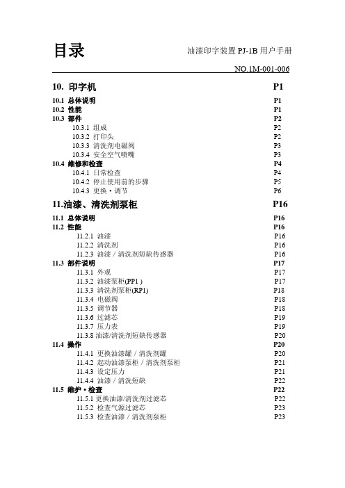
目录油漆印字装置PJ-1B用户手册NO.1M-001-006 10. 印字机P1 10.1 总体说明P1 10.2 性能P1 10.3 部件P210.3.1 组成P210.3.2 打印头P210.3.3 清洗剂电磁阀P310.3.4 安全空气喷嘴P3 10.4 维修和检查P410.4.1 日常检查P410.4.2 停止使用前的步骤P510.4.3 更换·调节P611.油漆、清洗剂泵柜P16 11.1 总体说明P16 11.2 性能P1611.2.1 油漆P1611.2.2 清洗剂P1611.2.3 油漆/清洗剂短缺传感器P16 11.3 部件说明P1711.3.1 外观P1711.3.2 油漆泵柜(PP1 ) P1711.3.3 清洗剂泵柜(RP1) P1811.3.4 电磁阀P1811.3.5 调节器P1811.3.6 过滤芯P1911.3.7 压力表P1911.3.8油漆/清洗剂短缺传感器P20 11.4 操作P2011.4.1 更换油漆罐/清洗剂罐P2011.4.2 起动油漆泵柜/清洗剂泵柜P2111.4.3 设定压力P2111.4.4 油漆/清洗短缺P22 11.5 维护·检查P2211.5.1更换油漆/清洗剂过滤芯P2211.5.2 检查气源过滤芯P2311.5.3 检查油漆/清洗剂泵柜P23NO.1M-001-006 11.6 冲洗P2411.6.1 需准备的物品P2411.6.2 冲洗步骤P2411.6.3 冲洗后重新起动的步骤P26 11.7 操作和检查P27 11.8 停止操作步骤P28 11.9 日常检查P28 11.10 定期检查P2911.10.1 季度检查P2911.10.2 半年检查P2911.10.3 全年检查P2912. 控制盘P35 12.1 总体说明P35 12.2 基本详述P36 12.3 说明P3712.3.1 前部P3712.3.2 后部P38 12.4 电器详述P3912.4.1 系统区域图解P3912.4.2 打印头驱动信号(输出)P3912.4.3 编码器信号(输入)P4112.4.4 外部信号(输入/输出) P4212.4.5 通信连接P4312.4.6 电源P4412.4.7 控制线路P45 12.5 控制功能P4512.5.1 控制P4512.5.2 打印字符P4712.5.3 打印功能P4812.5.4 打印式样P5012.5.5 通信功能P52 12.6 维护和检查P6712.6.1 检定P6712.6.2 打印头保险丝熔断测试P6812.6.3 打印头保险丝更换步骤P6912.6.4 错误编码表P70NO.1M-001-006 13. 手提终端P72 13.1 基本功能P72 13.2 说明P7213.2.1 小型键盘P7213.2.2 显示P7313.2.3 操作流程P74 13.3 操作步骤P7613.3.1 更改显示数据P7613.3.2 滚动显示数据P7713.3.3 传递数据P7713.3.4 创建数据P7813.3.5 删除数据P8213.3.6 记录数据P8413.3.7 状态要求P8513.3.8 参数传递1 P8613.3.9 参数传递2 P8813.3.10 设定传递条件P9113.3.11 记录外部字符P9213.3.12 传递时间编码P9613.3.13 错误步骤P97修订版第一版本:2000年9月。
产品管理创佳彩电产品介绍按功能

其他参数
音频系统
DK/GB/I/M
是否带音效
是
内置扬声器
内置扬声器2个
USB视频格式
视频:AVI、MPEG、MOV、VOB
音频:MP3、WMA、MAC、AAC
图片:BMP、JPEG、
工作电压
100-250V
待机功率
0.49
额定电压
220V
其他配置
说明书、遥控器
包装重量(kg)
34
保修政策
售后三包
保修年限
视频:MPEG2、AVI、H.264、
音频:MP3、WMA、MAV
图片:BMP、JPEG
720P
分辨率
1366X768
规格参数
机身重量
6.5kg
机身尺寸(长X宽X厚)
645x200x433(含底座)
输入输出
USB接口
1
HDMI端口
1
S-Video输入端口
/
AV输入端口
2
AV输出端口
/
YPbPr输入端口
1
其他参数
音频系统
DK/GB/I/M
是否带音效
是
内置扬声器
内置扬声器2个
USB视频格式
其他配置
说明书、遥控器
包装重量(kg)
30.7kg
保修政策
售后三包
保修年限
整机1年、屏幕3年
创佳电视32LME8800E6
基本参数
品牌
canca创佳
型号
32LME8800E6
颜色
黑色
外观用料
ABS
产品类目
LED
彩色制式
PAL/SECAM
面板类型
新维电动机保护器AMDL-O01-200使用说明书

AMDL-□/O01□ 系列电动机保护器使用说明 产品概述主要特点:单片机为核心,数字设定,数字显示,保护功能完备、保护性能可靠,零序电流检测。
保护功能:缺相、短路、接地、堵转、过载、电流不平衡、零序。
适用范围:额定电压不高于1140V,频率为50Hz或60Hz的三相交流电动机。
电动机保护器型号 AMDL-0.5 AMDL-1 AMDL-2AMDL-5AMDL-10AMDL-20AMDL-50 AMDL-100 AMDL-150AMDL-200最大设定电流(A) 0.55 1.1 2.3 5.5 11 23 55 110 165220最小设定电流(A) 0.1 0.2 0.4 1 2 4 10 20 30 40 电动机最大功率(KW) 0.22 0.4 1.1 2.2 4 11 22 45 75 110 电动机最小功率(KW) 0.055 0.11 0.22 0.55 1.1 2.2 5.5 11 18.5 22 电动机电源穿线孔Φ(mm)15 15 15 15 15 15 15 15 29 29 工作电压:AC 85V — 265V、DC 85V — 265V功率消耗:小于 2W采集精度:1.0环境温度:- 20℃ — 50℃继电器触点:AMDL-□/O011:1常开、常闭触点,AC 250V/10A(阻性负载)、DC 30V/10AAMDL-□/O012:2常开、常闭触点,AC 220V/5A(阻性负载)、DC 30V/5A 零序电流输入阻抗:小于 1 ΩAMDL-□/O01□系列电动机保护器数据显示AMDL-□/O01□系列电动机保护器,在电动机正常运行时,显示电动机的A、B、C相及零序电流;当电动机发生接地、短路、缺相、堵转、电流不平衡、过载、零序故障时,通过断开保护器内的继电器触点停止电动机运行(故障指示灯亮),同时显示故障代码指示电动机的故障类型,并且还显示发生故障时的A、B、C相及零序电流。
RT9199PSP中文资料
R1 = R2 = 100kΩ, RTT = 50Ω / 33Ω / 25Ω COUT(MIN) = 10μF (Ceramic) + 1000μF under the worst case testing condition RDUMMY = 1kΩ as for VOUT discharge when VIN is not presented but VCNTL is presented CSS = 1μF, CIN = 470μF (Low ESR), CCNTL = 47μF
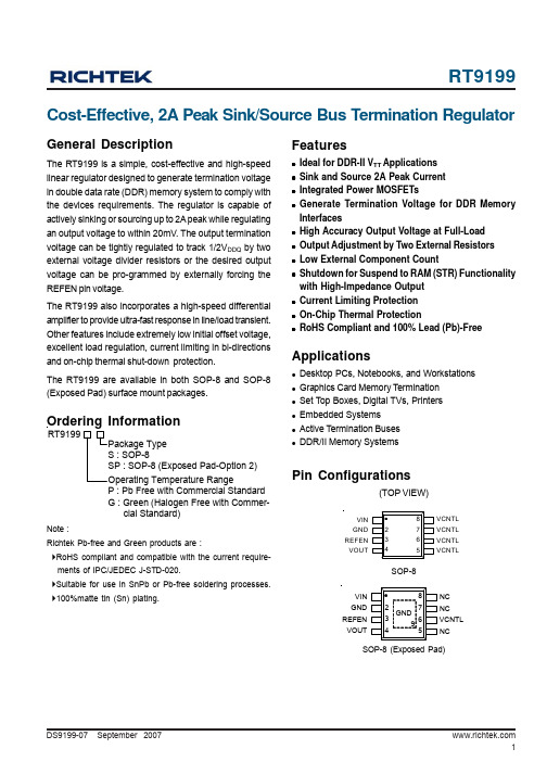
with High-Impedance Output z Current Limiting Protection z On-Chip Thermal Protection z RoHS Compliant and 100% Lead (Pb)-Free
Applications
z Desktop PCs, Notebooks, and Workstations z Graphics Card Memory Termination z Set Top Boxes, Digital TVs, Printers z Embedded Systems z Active Termination Buses z DDR/II Memory Systems
PS1K2U-P009中文资料
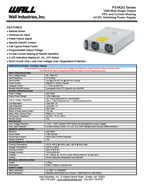
AC/DC Switching Power SupplyFEATURES● Remote Sense● Universal AC Input● Power Failure Signal● Remote ON/OFF Control● 0.98 Typical Power Factor● Programmable Output Voltage● Forced Current Sharing at Parallel Operation● 5 LED Indicators display AC, DC, OTP Status● Short Circuit/ Over Load/ Over Voltage/ Over Temperature ProtectionSPECIFICATIONS: PS1K2U SeriesAll specifications are based on 25o C, Nominal Input Voltage, and Maximum Output Current unless otherwise noted.We reserve the right to change specifications based on technological advances.INPUT SPECIFICATIONSInput Voltage Range 90 ~ 260VACInput Frequency 47 to 63HzInput Current 14A @ 215VAC (7A @ 230VAC) TypicalInrush Current RESULT A: 84.0A (Typical)Leakage Current < 7.0mA at 240VACRemote ON/OFF Control Compatible with a TTL signal to turn ON/OFFOUTPUT SPECIFICATIONSOutput Voltage See TableOutput Power Range 1200 Watts max.Output Voltage Adjustability 3% Typical adjustment by potentiometer20% ~ 100% Adjustment by 1 ~ 5VDC external control.Line Regulation Less than 1%Load Regulation Less than 1%Output Current See TableRipple & Noise (peak to peak) 1% maxSetup, Rise, Hold-Up Time RESULT A: 12.4msTemperature Coefficient ±0.04% / °C (0 ~ 50°C)Remote Sense YesPROTECTIONOver Voltage Protection 110% ~ 135% (variable “OVP” follows the adjustable DC output voltage)Over Load Protection Current limiting 3 times (1.5”, 3.0”, 5.0”) then intelligent auto recovery before shutdown. GENERAL SPECIFICATIONSEfficiency See TablePower Factor 0.98 (Typical)Power Failure Signal Open Drain of NPN TransistorParallel Operation YesENVIRONMENTAL SPECIFICATIONSWorking Temperature 0°C to +50°C @ 100% Load, +65°C @ 50% Load.Storage Temperature -20°C to +85°CWorking Humidity 20% to 90% RHStorage Humidity 10% to 95% RHVibration 10 ~ 200Hz, 2g 10 min./1cycle, Period of 60 min. for each axis.Cooling Power rating and temperature controlled fan.PHYSICAL SPECIFICATIONSWeight 3.75kgDimensions 279(L) x 203(W) x 63.5(H) mmSAFETY & EMCAC/DC Switching Power SupplyOUTPUT VOLTAGE / CURRENT RATING CHARTModel Number Output VoltageOutput CurrentMaximum Output PowerRipple & NoiseEfficiency PS1K2U-P009 9 VDC 133.3A 1200W 1% 83% PS1K2U-P012 12 VDC 100.0A 1200W 1% 84% PS1K2U-P015 15 VDC 80.0A 1200W 1% 85% PS1K2U-P018 18 VDC 66.6A 1200W 1% 85% PS1K2U-P024 24 VDC 50.0A 1200W 1% 88% PS1K2U-P030 30 VDC 40.0A 1200W 1% 88% PS1K2U-P036 36 VDC 33.3A 1200W 1% 88% PS1K2U-P048 48 VDC 25.0A 1200W 1% 89% PS1K2U-P06060 VDC20.0A1200W1%90%NOTES1. Dimensions of the mechanical drawing are shown in millimeters and inches.2. Weight of the unit is 3750 grams.DERATING CURVEAC/DC Switching Power Supply CONNECTOR PIN-OUT DRAWINGSAC/DC Switching Power Supply MECHANICAL DRAWING。
PD191 单相表用户手册说明书

南京能保电气有限公司版权所有本用户手册适用于PD191型产品V2.*版本程序。
本用户手册和产品今后可能会有小的改动,请注意核对你使用的产品与手册的版本是否相符。
1 说明书单独成册 2015-9-1823更多产品信息,请访问:目录第一章绪论 (1)第一节概述 (1)功能简述 (1)硬件配置 (1)第二节特点及参数 (2)技术特点 (2)技术参数 (2)第三节订货信息 (3)第二章安装 (4)第一节安装须知 (4)过电流保护 (4)浪涌保护 (4)第二节安装尺寸及方法 (4)端子介绍 (5)接线示意图 (6)第三章操作 (8)第一节面板图示 (8)第二节参数设定操作方法 (9)第四章通信 (12)第一节命令格式及示例 (12)第二节电量系数 (13)第三节数据地址 (14)PD191单相表用户手册第一章 绪 论第一节 概述PD191智能配电仪表是一种采集配电信息,具备数据传输的数字仪表,它集数据采集与控制功能为一身。
它可以代替多种仪表、继电器、变送器和其他元件。
PD191智能配电仪表可安装在配电系统内的不同位置。
PD191智能配电仪表,是针对电力系统、工矿企业、公用设施、智能大厦的电力监控需求而设计的配电仪表。
该系列每种产品分别对应测量常规单相电参数,如单相电流、电压、有功、无功功率,功率因数,开关状态等。
它还能接受远方的控制命令,输出相应的出口,完成远方控制功能。
它具有模拟量输出功能,自定义输出的电量。
功能简述硬件配置第二节特点及参数技术特点PD191的设计充分考虑了可靠性、简易性、性价比等方面,现具有以下特点: • 可直接从电流、电压互感器接入信号• 可任意设置PT/CT变比• 2路的开入量(隔离)输入• 2路的开出量(继电器)输出• 1路的模拟量输出4~20mA• 多块仪表可设置不同的通讯地址,多种通信速率供选择• 可通信接入SCADA、PLC系统中• 可与绝大多数PLC相连(GE、Siemens、AB等)• 可与业界多种软件通讯(inTouch、Fix、GMS800、组态王等)技术参数输入信号电压输入•额定电压:100V/380V•过载能力:1.2倍额定值(连续) 2500V/1秒(不连续)•输入负荷:小于0.2VA输入电流•额定电流:5A、1A•过载能力:1.2倍额定值(连续) 100A/1秒(不连续)•输入负荷:小于0.2VA频率输入:45~55 HZ测量精度•电压、电流精度:0.5级•其他电量精度:1级•频率精度:0.1Hz通信•通信接口:RS-485 ,异步半双工,1位起始位,8位数据位,1位停止位,无校验•协议:MODBUS-RTU•波特率:4800~9600 bps工作环境•工作温度:-20℃~60℃• 存储温度:-40℃~75℃•相对湿度:5%~90%不结露信号开入• 接入方式:干接点接入• 光电耦合器隔离:4000VAC.rms信号开出• 输出方式:脉冲输出,遥控脉冲宽度为1秒• 继电器输出容量:5A/250VAC,5A/30VDC外形尺寸和重量• 长宽深:72x72x95mm• 净重:0.25KG电源• 工作电压:AC/DC 60~265V• 最大功耗:≤3W第三节订货信息第二章安装第一节安装须知过电流保护过电流保护建议在装置电源处加入1A的保险丝或空开。
SoMachine Basic中文培训手册

购买 SoMachine Basic 培训手册的用户即享有参加 SoMachine Basic 培训课程的权利。 必须通过课程测验,方可获得施耐德电气的培训课程结业证书。
对依据本培训手册做出的行为,施耐德电气不承担任何责任。
商标
施耐德电气已尽最大努力提供有关本手册中提及的公司名称、产品和服务的商标信息。以下显示的商标来自不同来源。
符合资格的人员指的是具备电气设备的构建和操作,以及安装方面的相关技能和 知识,并已接受安全培训,能够识别并规避相关危险的人员。
iv
SoMachine Basic 版本 1
2013 年 9 月
课程开始前
本培训手册 的范围
本培训手册是对授权培训的一项补充。为了正确使用软件,学员应同时参考产品 提供的文档,如帮助文件、用户指南或知识库。
在安装和使用本产品时必须遵守各相关州、地区和地方安全规定。基于安全原因,也为了帮助确保与存档的系统数据相符,仅制 造商可以执行零部件维修。
当装置用于对技术安全有特定要求的应用场合时,必须遵循相关指示。
如不搭配使用施耐德电气的软件或经认可的软件可能导致人员受伤、设备损害或运行异常。
拒不遵守本信息可能导致人员受伤或设备损坏。 © 2013 施耐德电气 保留所有权利。 本手册内容属施耐德电气专有财产。施耐德电气保留所有权利,包括版权。未征得施耐德电气明确的书面许可,不得以任何形式 或通过任何方式,不论是电子或机械形式(包括影印),复制本文件的任何部分。
SoMachine Basic
手册 第 1 次发布
vii
课程开始前(续)
用户责任 (续)
替换在本培训文件所描述的实例中使用的一些主要软件功能和/或硬件部件,会严 重损害应用的性能。更为严重的是,任何此种替换或更改可能会使本文件和其它 相关文档中指定的建议结构、描述、指示、布线图和/或各种硬件部件和软件功能 之间的兼容性完全失效。请务必清楚认识到任何更改、添加或替换所带来的后 果。如果出现以下条件,根据 EN/ISO 12100-1,条款 5 所定义的一项残余风险将 继续存在:
SONYRM-VL1000学习型遥控器的使用说明

SONYRM-VL1000学习型遥控器的使用说明SONY RM-VL1000 学习形遥控器的使用一、设置时间(P8)Set-> CLOCK-> STD TIME(标准时间)或DS TIME(夏时制)-> 用↑↓键设置星期-> 用←→改变栏目,用↑↓改变时间的数值-> Set确认二、预置(P13)Set-> PRESET-> 选设备(SCROLL换页)-> 输入四位数代码(可以在附表中查代码,在不知道代码时可以按CH+或CH-改变代码,用POWER测试)-> 按ENT确认-> Set确认三、使用(P21)COMPO->选设备(SCROLL换页)-> 按屏幕右侧提示选定设备-> 正常使用四、清除设置(P19)Set-> SCROLL换页选CLEAR-> 选COMPO->选设备(SCROLL 换页),等一小会儿就可以删掉注:COMPO也可换成SYSTEM,TEMER等。
注:ALL选项五、清除按键(P29)已经学过的键不能再学习,必须先清除后学习,清除的方法为:在设置时按住要清除的键同时按SCROLL键听到一个长B声就表示已经清除成功了。
六、学习(P23)对准遥控器(5-10CM)-> Set-> LEARN->选设备(SCROLL换页)-> 按要学习的按键-> 在10秒内按被学习的一个键(成功会听到一个b声,不成功会显示NG)->完成后按SET 注:如果有的设备需要同时按两个的按键才能完成的一个操作,可以在学习时把两个按键同时学习进入一个按键即可,此遥控器使用时不可以按两个按键完成一个操作。
(P26)注:此此方法适应其它想删除按键如SYSTEM,COMPO等等。
七、在其它设备中使用TV或AMP的音量控制(P30)SET->VOLUME(SCROLL换页)-> 如改变(TV,SAT,CABLE,DVD,VCR1,VCR2,DVR)成TV控制可选择VISUAL下的TV,如改变(AMP,CD,MD/DAT,TAPE A,TAPE B)成AMP控制可选择AUDIO下的AMP->选TV或AMP(SCROLL换页)-> SET 确认八、系统命令(多条命令)(P34)SET-> SYSTEM(SCROLL换页)-> SYSTEM-> 选SONY OFF 或SYSTEM2-12->选设备(SCROLL换页)-> 按命令按键-> 按COMPO再选其它按键-> 重复以上步骤可多选其它按键-> SET 注:如果在两分钟内没按SET,所设的多条命令自动取消。
深度系统维护光盘Plus典藏版
深度系统维护光盘Plus典藏版软件大小:692.06 MB软件语言:简体中文软件类别:国产软件 - 软件光盘 - 维护光盘区运行环境:Win9X/2000/XP/2003/Vista/推荐导航:中国最牛B的网址站更新日期:2008-12-27 15:22:42首先感谢opera_888所提供的PE下的Opera 九天集成绿色版、小兵的一键还原工具、桃夭的OFFICE等一、光盘特点1、集成双PE(深度2.5 & WinPE liqiushi188 加强版),拥有更强的兼容性2、光盘启动下的DOS工具多,便于维护3、Windows环境下,集成较多维护工具,不集成更新较快的软件。
4、详细的日志管理体系以及光盘完整性验证功能......做到一盘在手,维护无忧~~~二、光盘组成1、WIN模块:全部是Windows环境下所使用的维护工具,几乎没有网络更新软件,以保证光盘不过时。
其中包含光盘完整性检测模块,核心为批处理。
2、DOS模块:使用EasyBoot制作的光盘启动画面,可由光盘启动。
DOS模块又分为三个模块:PE、综合维护工具、硬件维护工具(均是DOS环境下使用的)三、软件与维护工具WIN模块:深度一键还原工具 2009一键Ghost 080808 奥运版雨林木风 OneKey Ghost3.2资料转移向导简单驱动备份与还原EasyRecovery_Pro 文件恢复深度驱动识别包 V1.5驱动精灵 2008 Beta5.2Norton PartitionMagic 硬盘工具自定义分区转为NTFS格式Everest 硬件及系统环境检测虚拟光驱 Virtual Drive ManagerEverest 硬件及系统环境检测CPU-Z CPU检测工具DisplayX 显示器测试工具MemTest 物理内存检测器SuperPI MOD 经典测试工具ATTO 磁盘性能测试Filemon 文件监视程序Windows 优化大师 7.83.8.721 破解版Deepin XP 系统优化与设置 V1.6.4 Ylmf DIY_1.6系统服务一键通微软优化工具Windows 2000/XP 服务优化向导ClearType 字体清晰软件深度双核补丁智能安装包 V4.5.11.1 一键清理垃圾文件填IP地址为:192.168.0.178填IP地址为:192.168.1.178IP 地址修改器TCPIP 并发连接数修改 For XP SP2 TCPIP 并发连接数修改 For XP SP3 系统自动登录器运行输入法设置工具系统快速设置工具 V4.3 STYLEXP主题资源包 V2.9安装倚风 VISTA 风格包 2.3XP变脸王 V9.3 奥运版Windows Blinds 6.0 绿色中文破解版ClearType 字体清晰软件Photoshop CS3 Ylmf版Office 2003 桃夭精简版批处理编译程序汉化版安静的替换系统文件微软序列号算号器(免杀版)HyperSnap 6 截图工具Hash 文件校验工具暴力文件删除器 V1.4EasyBoot 5.1 绿色破解版UltraISO 8.66 YlmF版专用链接转换器冰刃文件信息:文件: Deepin_Tools_CD_Plus.iso大小: 725673984 字节MD5: 0F6FADABDE094B1042E505E2FAB9300ASHA1: 0BA3F89DE5640E91622E663DD43F9B65933B1445 CRC32: D410E683。
S22MD1P资料
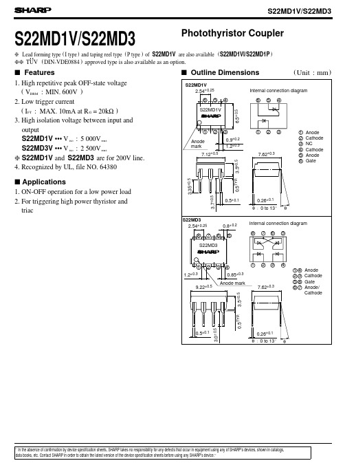
Photothyristor CouplerS22MD1V/S22MD3s Features1. High repetitive peak OFF-state voltage (V DRM2. Low trigger current(I FT :MAX. 10mA at R G =20k Ω)3. High isolation voltage between input and outputs Applications1. ON-OFF operation for a low power load2. For triggering high power thyristor and triacs Outline Dimensions(Unit :mm )S22MD1V ••• V iso S22MD3V ••• V iso g S 22MD1V and S22MD3 are for 200V line.:MIN. 600V )gg TUV (DIN-VDE0884) approved type is also available as an option.4. Recognized by UL, file NO. 64380are also available () g Lead forming type (I type ) and taping reel type (P type ) of S22MD1V S22MD1VI/S22MD1P :5 000V rms :2 500V rms..-30020406080100T r m s )Ambient temperature T a (˚C)Fig. 1 RMS ON-state Current vs. Ambient Temperature-30255075100125010203040506070Fig. 2 Forward Current vs. Ambient TemperatureF o r w a r d c u r r e n t I F (m A )Ambient temperature T a (˚C)00.51.0 1.52.0 2.53.0Fig. 3 Forward Current vs. Forward VoltageF o r w a r d c u r r e n t I F (m A )Forward voltage V F (V )-30020*********02468101220k Ω50k ΩFig. 4 Minimum Trigger Current vs.Ambient TemperatureR G =10k ΩAmbient temperature T a (˚C )M i n i m u m t r i g g e r c u r r e n t I F T (m A )125102050100200125102050100Fig. 5 Minimum Trigger Current vs. Gate ResistanceM i n i m u m t r i g g e r c u r r e n t I F T (m A )Gate resistance R G -30-20020406080100120Fig. 6 Break Over Voltage vs.B r e a k o v e r v o l t a g e V B O (V )Ambient temperature T a (˚C )V D =6V R L =100ΩV D =6V R L =100ΩT a =25˚C(m A R M S O N -s t a t e c u r r e n t I 100200(k Ω)Ambient TemperatureFig. 7 Critical Rate of Rise of OFF-state Voltage vs. Ambient Temperature20406080100D R M (A )Ambient temperature T a (˚C )101010C r i t i c a l r a t e o f r i s e o f O F F -s t a t e v o l t a g e R e p e t i t i v e p e a k O F F -s t a t e c u r r e n t I Fig. 8 Holding Current vs.Ambient Temperatured V /d t (V /µs )+V V +V V INs Basic Operation Circuit+V V +V V q S22MD1Vq AC 100V, 200VMedium/High Power Thyristor Drive CircuitqPlease refer to the chapter “Precautions for Use”(Page 78 to 93).Application CircuitsNOTICEq The circuit application examples in this publication are provided to explain representative applications of SHARP devices and are not intended to guarantee any circuit design or license any intellectual property rights. SHARP takes no responsibility for any problems related to any intellectual property right of a third party resulting from the use of SHARP's devices.q Contact SHARP in order to obtain the latest device specification sheets before using any SHARP device.SHARP reserves the right to make changes in the specifications, characteristics, data, materials, structure, and other contents described herein at any time without notice in order to improve design or reliability. Manufacturing locations are also subject to change without notice.q Observe the following points when using any devices in this publication. SHARP takes no responsibility for damage caused by improper use of the devices which does not meet the conditions and absolute maximum ratings to be used specified in the relevant specification sheet nor meet the following conditions:(i) The devices in this publication are designed for use in general electronic equipment designs such as:--- Personal computers--- Office automation equipment--- Telecommunication equipment [terminal]--- Test and measurement equipment--- Industrial control--- Audio visual equipment--- Consumer electronics(ii)Measures such as fail-safe function and redundant design should be taken to ensure reliability and safety when SHARP devices are used for or in connection with equipment that requires higher reliability such as:--- Transportation control and safety equipment (i.e., aircraft, trains, automobiles, etc.)--- Traffic signals--- Gas leakage sensor breakers--- Alarm equipment--- Various safety devices, etc.(iii)SHARP devices shall not be used for or in connection with equipment that requires an extremely high level of reliability and safety such as:--- Space applications--- Telecommunication equipment [trunk lines]--- Nuclear power control equipment--- Medical and other life support equipment (e.g., scuba).q Contact a SHARP representative in advance when intending to use SHARP devices for any "specific"applications other than those recommended by SHARP or when it is unclear which category mentioned above controls the intended use.q If the SHARP devices listed in this publication fall within the scope of strategic products described in the Foreign Exchange and Foreign Trade Control Law of Japan, it is necessary to obtain approval to export such SHARP devices.q This publication is the proprietary product of SHARP and is copyrighted, with all rights reserved. Under the copyright laws, no part of this publication may be reproduced or transmitted in any form or by any means, electronic or mechanical, for any purpose, in whole or in part, without the express written permission of SHARP. Express written permission is also required before any use of this publication may be made by a third party.q Contact and consult with a SHARP representative if there are any questions about the contents of this publication.。
MultieterBuddy(MMB)QuickStart
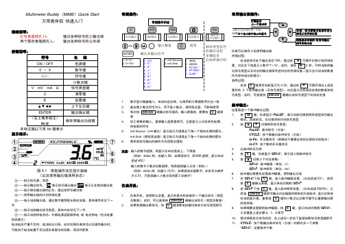
Multimeter Buddy(MMB)Quick Start万用表伴侣快速入门接线说明:红色表笔插孔H:输出各种信号的正输出端两个黑色表笔插孔L:输出各种信号的公共端按键说明:符号名称ON/OFF 电源键0 ~9 数字键+/-符号键·小数点键V mV mA Ω信号类型键C 清零键E 设置键▲▼◄►上下左右键ENTER 输出确认键(右上角未标注)Hz键频率类输出功能键显示指示:图5.1 常规操作状态显示画面(以及常用输出值调用状态)①――指示信号源,常亮②――指示输出信号,“ON”表示信号确认输出“OFF”表示正在修改输出值③――指示修改输出值的正负,通过按符号键切换④――常用输出值的计划存储位置⑤――指示当前输出值,通过数字键等配合修改该值,具体操作详见下一节⑥――指示当前输出信号类型,具体内容详见下一节⑦――指示当前供电状态:外部电源适配器供电或电池供电(包含电量信息提示)电池电压严重不足时,电池标志闪烁。
此时切换仪表信号以及操作输出时,可能由于电池电量不足出现仪表复位的现象。
请及时更换常规操作:电压l输出1. 0~1V2. 0~10VmV输出电流输出电阻输出1. mA Source2. mA Sink1. 400Ω2. 4000Ω3. PT100 *4. PT1000 *5. Cu50 *1. mV2. K *3. E *4. J *5. T *6. R *7. B *8. S *9. N *常规操作状态~输入数值清零09+/-.CVΩmAmVENTER确认并输出信号频率类信号输出Hz频率类型信号的输出过程步骤较多后面单独介绍1. 数字显示随着键入,自动向左位移,与常用的计算器使用方法一致2. 最右侧小数点符号为%,而不是小数点,请特别注意,不影响使用3. 每次按ENTER键输出信号值后,输入新值前,需要按C键清零4. 热工参数的输入,直接输入温度值即可,注意显示上对应的热电偶、热电阻的符号5. mA Source(mA输出)显示指示为液晶左下角一个指向左侧的箭头。
MANS-9D操作说明

MANS-9D线切割控制系统(V4.5版)第一章功能概述9D线切割控制系统是本公司采用当今最先进的计算机实时控制和图形交互显示技术,结合线切割数控和自适应技术开发的高级复杂的数控系统。
9D系统具有以下功能特性:1.是基于Autop编程的控制系统,Autop的数控加工程序直接内部数据相连至9D,无需额外操作键盘(比如不需将数控程序存盘然后退出Autop再去调盘),退出Autop后图形直接出现在9D主控画面。
2.是基于MANS-8D编控系统的控制系统,继承了有十几年历史的MANS系统的软件稳定性以及操作流畅性,所有加工控制按键完全相同8D系统为组合按键,在任何情况下加工按键取作用(即是说进入Autop编程介面后仍然可以按键控制机床暂停加工等)。
3.软硬件强可靠性设计。
软件固化在电子IC中,绝对防病毒。
硬件采用优质线路板,所有元器件均焊死在板上,不会出现“接触不良”,使用免维护电池,不会漏汤。
4.真正的微电脑控制系统。
所有插补运算及控制由PC微电脑发出,所以工作时不能再玩游戏。
同时,锥度切割时追求准确无误,出现走Y轴锥度时,X轴马达有微动。
5.自带3B全屏幕编程器,弥补Autop编程上的缺陷。
功能包括输入程序、调3B文件,存3B文件,加工比例设置,开始行设置,数据变换,图形变3B,3B编译到图形区。
6.全自动分时操作,加工时编程可照常进行,在9D介面可按键显示加工图形或编程图形。
7.含绘图显示子系统,可任意调整图形的显示状态,如比例,中心位置。
加工轨迹实时跟踪显示。
锥度工件分颜色显示基准面和锥度面,上下面加工座标显示的颜色对应两图形面颜色。
锥度参数显示。
加工状态显示,高频以及步进进给显示。
8.完善的加工功能,包括停电记忆,变锥加工,模拟加工,短路自动回退,逆加工,马达阻尼,段停,缩放加工,变换加工。
先进的马达阻尼功能,防止步进马达突然加速,从而防止加工短路。
9.准确加工大锥度,丝架参数自动校正功能。
10.CAD转换功能。
- 1、下载文档前请自行甄别文档内容的完整性,平台不提供额外的编辑、内容补充、找答案等附加服务。
- 2、"仅部分预览"的文档,不可在线预览部分如存在完整性等问题,可反馈申请退款(可完整预览的文档不适用该条件!)。
- 3、如文档侵犯您的权益,请联系客服反馈,我们会尽快为您处理(人工客服工作时间:9:00-18:30)。
PCB ordering information - page 30SERIES-INSULATOR STYLE-MATERIAL SERIES-INSULATOR STYLE-MATERIALMDB - Screw mounting-Diallyl phthalate MDVB - Screw mounting-Polyester H -Insulated solid or stranded wire L -Uninsulated solid wireS -Solder pot to accept #26 AWG max.harness wire.No designator - No hardware - standard mounting .091 (2.31) hole diameterP -JackpostK -Jackscrew-standard L -Jackscrew-low profile F -Float mountM -Military specification hardware, see page 13.1-.050 (1.27) centers9-15-21-25-31-37-51. See page 9P -Pin S - SocketCONTACT SPACIN GCONTACT ARRAN G EMENTCONTACT TYPECONTACT SPACIN G CONTACT ARRAN G EMENT CONTACT TYPE TERMINATION TYPE TERMINATION TYPELOC K IN G H AR DW ARE (SCRE W MOUNTIN GONLY )TERMINATION CO D E LOC K IN G H AR DW AREM D** 1-9P H 001P(H) 001 - 18",7/34strand, #26 AWG, MIL-W-16878/4,T ype E T eflon, Y ellow.(H) 003 - 18",7/34strand, #26 AWG, MIL-W-16878/4,T ype E T eflon, color coded to MIL-S T D-681System I.(L) 1 - 1/2"uninsulated solid #25 AWG gold plated copper.(L) 2 - 1"uninsulated solid #25 AWG gold plated copper.TERMINATION CO D ERo H S COMPLIANCERSee page 79 and 81for additional codesDimensions shown in inch (mm)Specifications and dimensions subject to changeHow to OrderMicrominiature Rectangular Connectors with MICRO-Pin Contacts on .050 (1.27)centers.MICRO-D microminiature rack/panel connec-tors are used in applications requiring highly reliable, extremely small, lightweight connec-tors. These connectors are available in 2 insu-lator materials, 2 mounting variations, 7 shell sizes accommodating from 9 to 51 contacts and a special arrangement of 5 micro contacts and 2 coaxials. The insulator materials listed give the MICRO-D connector wide versatility in most applications required by industry.ITT can also terminate a wide variety of stranded or solid wire directly to MICRO-D contacts, which is often desirable in high den-sity arrangements.MICRO-D connectors can also be custom har-nessed to meet any customer requirement of single or multiple connectors. Pigtail lead and harness description must be given by the cus-tomer. A typical description would be: .5" #25AWG, gold plated copper leads or 18" of #26yellow, Teflon-insulated, Type E wire. Shown below are various methods of termination.Consult customer service for any routine or complex harnessing of MICRO-D connectors.•Glass-filled diallyl phthalate thermoset material used in high temperature applica-tions that is immune to cleaning solvents.It also has excellent dielectric properties.Temperature range: -65˚F to +300˚F (-55˚C to +149˚C).•Glass-filled polyester thermoplastic that is not affected by cleaning solvents and exhibits excellent dielectric properties.Temperature range: -55˚F to +257˚F (-65˚C to +125˚C).SpecificationsMATERIALS AND FINISHESShell/Insulator (One Piece)MD/MDB: Glass-filledthermoset plastic MDV/MDVB: Thermoplastic ELECTRICAL DATA MECHANICAL FEATURES No of ContactsSize or Length Coupling PolarizationContact Spacing Centers Shell StylesConsult factory for availabilty.Coaxial CableWire SizeContact Termination -9to 51: (1 arrangement of 5 contacts and 2 coaxials - for screw mount only)-7sizes-Friction/jackscrews-Keystone-shaped shells -.050 (1.27mm)-Plug and receptacle-RG-178/U (Not available for MD clip mount)-#24 thru #32 AWG -Multi-indent crimp-Copper alloy, gold plateContactsDimensions shown in inch (mm)Specifications and dimensions subject to changeStandard Wire Termination CodesCavity #1 black*The following termination codes are listed for your information. For additional codes please refer to Appendix on page 79 and 81. All wire lengths are minimum.#26 A WG per MIL-W-16878 Type E Teflon ,stranded.H arness Typ e (H)L ength 3(76.2)6(152.4)8(203.2)10(254.0)12(304.8)18 (457.2)20(508.0)24(609.6)30(762.0)36(914.4)48(1219.2)72(1828.8)120(3048.0)H020H019H026H029H028H001H038H009H010H011H013H017H042H027H016H034H025H002H003H023H004H005H006H048H046H041L61L 56L 57L 39L 58L 1L 14L2L 7L6L 16L 10.125(3.18).150 (3.81).190(4.83).250 (6.35).375(9.52).500 (12.70).750 (19.05)1.000 (25.40)1.500 (38.10)2.000 (50.80)2.500 (63.50)3.000 (76.20)All Y ell o w Co l o r Cod e d*T erminati o n Cod eL ength #25A WG G old P lated CopperS o li d U ninsulate d Typ e (L)With Screw Mounting Holes (Conforms to MIL-DTL-83513)MDB.110(2.79)MAX..154(3.91)(5.08)MAX.Solder PotSolder PotGlass-filled Diallyl Phthalate Plastic InsulatorMDVBGlass-filled Polyester Plastic InsulatorRPart Number by Shell Size Add lead type and length, see Part Number Explanation.Weight given is with 1/2", uninsulated solid #25 AWG gold plated copper pigtails.*****AMax.B Max.C Max.D Max.E Max.F ±.005Avg.Weight***±5% (oz.)±5% (gm.)MDB1-9S**MDB1-15P**MDB1-15S**MDB1-21P**MDB1-21S**MDB1-25P**MDB1-25S**MDB1-31P**MDB1-31S**MDB1-37P**MDB1-37S**MDB1-51P**MDB1-51S**MDVB1-9S**MDVB1-15p**MDVB1-15S**MDVB1-21P**MDVB1-21S**MDVB1-25P**MDVB1-25S**MDVB1-31P**MDVB1-31S**MDVB1-37P**MDVB1-37S**MDVB1-51P**MDVB1-51S**.788 (20.02).788 (20.02).938 (23.82)1.088 (27.64)1.088 (27.64)1.188 (30.18)1.188 (30.18)1.338 (33.98)1.338 (33.98)1.488 (37.80)1.488 (37.80)1.438 (36.52)1.438 (36.52).292 (7.42).380 (9.65).442 (11.23).592 (15.04).680 (17.27).692 (17.58).780 (19.81).842 (21.39).930 (23.62).992 (25.20)1.080 (27.43).942 (23.93)1.030 (26.16).408 (10.36).408 (10.36).588 (14.17).708 (17.98).708 (17.98).808 (20.56).808 (20.56).958 (24.33).958 (24.33)1.108 (28.14)1.108 (28.14)1.058 (26.87)1.058 (26.87).173 (4.39).173 (4.39).173 (4.39).173 (4.39).173 (4.39).173 (4.39).173 (4.39).173 (4.39).173 (4.39).173 (4.39).173 (4.39).220 (5.59).220 (5.59).218 (5.54).218 (5.54).218 (5.54).218 (5.54).218 (5.54).218 (5.54).218 (5.54).218 (5.54).218 (5.54).218 (5.54).218 (5.54).260 (6.60).260 (6.60).565 (14.35).565 (14.35).715 (18.16).865 (21.97).865 (21.97).965 (24.51).965 (24.51)1.115 (28.32)1.115 (38.32)1.265 (32.13)1.265 (32.13)1.215 (30.86)1.215 (30.86).026 (0.73).025 (0.70).038 (1.10).053 (1.50).050 (1.40).063 (1.80).056 (1.60).080 (2.30).073 (2.10).086 (2.45).076 (2.15).109 (3.10).093 (2.64)Dimensions shown in inch (mm)Specifications and dimensions subject to changeMD*B-PCB connectors use standard MD*B all plastic shells and are designed for use with flex circuitry, printed circuit and multi-layer boards. They are easily mounted and soldered and provide high density/high reliability in board-to-board and board-to-cable applica-tions. While being similar to the MDM-PCB connectors, the MD*B-PCB connectors are all plastic, extremely small, and lightweight yet rugged enough for use in the most demanding applications.MD*B-PCB connectors are available inseven shell sizes with 9 to 51 contacts in the popular 90°narrow profile PCB termination,with a variety of tail lengths for varying boardthickness.How to OrderSERIESCONTACT ARRANGEMENT CONTACT TYPE CTERMINATION TYPE THARDWAREHTERMINATION TAIL LENGTH TMODIFICATION CODES C(Consult Factory)MMD*B--37S CBR ** * *L39RoHS COMPLIANCE RJackpost mounting for use with locking hard-ware is also available.If the connectors shown in the catalog do not meet the requirements of your applica-tions, a special shape, size or layout using the basic all plastic shell can be made avail-able. For further technical and applications information, contact customer service.CONNECTOR SERIES MDVB, MDBCONNECTOR ARRANGEMENT9, 15, 21, 25, 31, 51CONTACT TYPES =Socket P =PinTERMINATION TYPECBR = 90°Narrow Profile PCB Terminations HARDWAREP =JackpostM7 = Jackposts, M635135-07No Letter = Less HardwareTERMINATION TAIL LENGTH CODESNONE –.109 (2.77) ±0.15 (0.38) Standard L61– .125 (3.18)L66– .150 (3.81)L57– .190 (4.83)L39–.250 (6.35)L58– .375 (9.52)Dimensions shown in inch (mm)Specifications and dimensions subject to changeCBR Series (90˚ Mounting Narrow Profile)TYP ..186 (4.72) PLUG 9-15-21-25 VIEW*FOR 31: 1.085 (27.56) MAX. FOR 37: 1.185 (30.10) MAX. FOR 51: 1.225 (31.12) MAX.I A. TYPPCB Termination Arrangements (Viewed from bottom of connector, on PCB solder side.)Indentification number shown for plug connector, use reverse order for socket connector..083.020.0209Contacts15 Contacts21 Contacts 25Contacts51 Contacts37 Contacts31 ContactsAll Termination Configurations .100 (2.54) x .100 (2.54) Grid Pattern, Offset .050 (1.27)*For jackpost locking add letter "P" or "M7".NOTE: Standard lead termination is #24 AWG, solid copper, solder or tin dipped.Part Number By Shell Size MD*B-9PCBR*MD*B-9SCBR*MD*B-15PCBR*MD*B-21PCBR*MD*B-21SCBR*MD*B-25PCBR*MD*B-25SCBR*MD*B-31PCBR*MD*B-31SCBR*MD*B-37PCBR*MD*B-37SCBR MD*B-51PCBR*MD*B-51SCBR.788 (20.01).938 (23.82)1.088 (27.63)1.088 (27.63)1.188 (30.17)1.188 (30.17)1.338 (33.98)1.338 (33.98)1.488 (37.79)1.488 (37.79)1.438 (36.52)1.438 (36.52).565 (14.35).715 (18.16).865 (21.97).865 (21.97).965 (24.51).965 (24.51)1.115 (28.32)1.115 (28.32)1.265 (32.13)1.265 (32.13)1.215 (30.86)1.215 (30.86).292 (7.42).525 (13.34).592 (15.04).675 (17.14).692 (17.58).775 (19.68).842 (21.39).925 (23.50).994 (25.25)1.075 (27.30).942 (23.93)1.026 (26.06).218 (5.54).218 (5.54).218 (5.54).218 (5.54).218 (5.54).218 (5.54).218 (5.54).218 (5.54).218 (5.54).218 (5.54).258 (6.55).258 (6.55).134 (3.40).218 (5.54).134 (3.40).218 (5.54).134 (3.40).218 (5.54).134 (3.40).218 (5.54).134 (3.40).218 (5.54).177 (4.50).258 (6.55).420 (10.67).420 (10.67).420 (10.67).420 (10.67).420 (10.67).420 (10.67).420 (10.67).420 (10.67).520 (13.21).520 (13.21).550 (13.97).550 (13.97).250 (6.35).250 (6.35).250 (6.35).250 (6.35).250 (6.35).250 (6.35).250 (6.35).250 (6.35).250 (6.35).250 (6.35).300 (7.62).300 (7.62).230 (5.84).130 (3.30).130 (3.30).130 (3.30).130 (3.30).130 (3.30).130 (3.30).130 (3.30).130 (3.30).130 (3.30).150 (3.81).150 (3.81)A Max.B±.005 (0.13)G±.010 (0.25)H±.010 (0.25)C Max.D Max.E Max.F Max.Dimensions shown in inch (mm)MDB Coaxial Series with Screw Mounting HolesMDB connectors with two coaxial and five MICRO-PIN TM /MICROSOCKET TM contacts. Crimp-type coaxial contacts accommodate RG-178/U cables. A plastic insertion/extraction tool is supplied with each connec-tor assembly having removable coaxial assembly.How to Order - MDB CoaxialSERIESMDB1-7C2****SHKSERIESMicro-D CoaxialNo Letter - Coaxial assemblyinstalled and nonremovable RO - coaxial assembly ordered serparatelyRA - Coaxial shipped assembled but uninstalled See Standard Wire TerminationConsult customer serviceNo letter - No hardware*Not available with removalbe coax cable type connectors RO and RA.standard mounting. 091 (2.31) hole diameter F -FloatK -Jackscrew (standard)L -Jackscrew (low profile)P -JackpostCode on page 29. Coaxial cable will beRG-178U unless otherwise specified; length will be same as wire modification.P -Pin S -Socket L -Uninsulated, solid wireH -Insulated, solid or stranded S -Solder pot*1-.050 (1.27) centers...................7 (2)SIGNAL CONTACT SPACING TOTAL CONTACT CAVITIES NUMBER OF COAXIALS SIGNAL CONTACT SPACING TOTAL CONTACT CAVITIES NUMBER OF COAXIALS COAXIAL TYPECOAXIAL TYPESIGNAL CONTACT TYPE SIGNAL CONTACT TYPESIGNAL CONTACT LEAD TYPE SIGNAL CONTACT LEAD TYPESIGNAL CONTACT LEAD LENGTH SIGNAL CONTACT LEAD LENGTH MODIFICATIONHARDWAREMODIFICATION HARDWARERoHS COMPLIANCE RHow to Order - Coaxial Cable AssembliesSERIESMDCCS** * *COAXIAL CABLE CONTACT TYPE CONTACT TYPE COAXIAL CABLE TYPECOAXIAL CABLE TYPE COAXIAL CABLE LENGTHCOAXIAL CABLE LENGTHSERIES MDP -Pin(used with socket side connection)S -Socket(used with pin type connection)See Standard Wire TerminationCodes on page 29. Coaxial cable will be RG-178U unless otherwise specified; length will be the same as wire modfication.1-RG178/UCOAXIAL CABLE CCRoHS COMPLIANCE RDimensions shown in inch (mm)Specifications and dimensions subject to changeDimension - MDB Coaxial SeriesPlugReceptacle(See page 9 for layouts)Part Numberby Shell SizeMDB1-7C2P*MDB1-7C2S*.510 (12.95).602 (15.29)* Add lead type and length, see Part Number Explanation.** Weight given is with 7 inch (177.80) insulated leads, #26 AWG silver plated copper pigtails and RG178/U coaxials..204 (5.18).185 (4.70).298 (7.57).279 (7.09).782 (19.86).782 (19.86).395 (10.03).375 (9.52).510 (12.95).540 (13.72).290 (8.30).273 (7.80)A Ma x.B Ma x.C Ma x.E Ma x.E 1Ma x.D +_.005 (0.13)Av g .W eight**(oz)+_5% (gm .)+_5%TWO MTG. HOLES RO AND RA COAXESRO AND RA COAXESMounting Hardware Views (Sizes 9-51)This hardware supplied unassembled.Screw Lock Assembly90˚ Angle Mounting BracketDescriptionScrew Lock Assembly Jackpost Kit322-9500-000 320-9505-000015-9516-000 .100 (2.54) .122 (3.10) .257(6.53).215(5.46)015-9516-000 Mounting Bracket, 90˚ Angle- MD*1for 9 thru 37 Shell Sizes MD*1for 51 Shell SizeNOTES: Screw lock assembly (322-9500-000) can be used for front front mounting. Jackpost kit(320-9505-000) consists of 2 assemblies, shipped unassembled.Part Number ±.005 (0.13)Max.*NOTE: Torque value is 4.0 in/lbs max. REF. ONLY_.003_0.08)FACEFACECONNECTOR HEX HEAD -Jackscrew - (L) Low ProfileJackscrew - (K) StandardThis hardware is factory installed.Shown here is a cutaway view of the float mount for the MD connector.The basic shell dimensions are the same for the float mount and the screw mounting hole configurations. View shown is for standard float mount front panel mounting. Reverse mounting is available on request.*NOTE: Torque values are as follows: Low Profile Jackscrew (L)-2.5 in/lbs Standard Jackscrew (K)-2.5 in/lbsDimensions shown in inch (mm)Specifications and dimensions subject to changeMounting Hardware to Military Specification (Sizes 9 - 51) PER MIL-DTL-83513/5This hardware supplied unassembled.Jackscrew - (L) Low profile *.062 (1.57)HEX. (REF.).092 (2.34) DIA.Allen headPlug and Receptacle Low and High Profile Slotted HeadJackpost AssemblyDescriptionSlotted Head Jackscrew Assy Low ProfileSlotted Head Jackscrew Assy High Profile Allen Head Jackscrew Assy Low Profile Allen Head Jackscrew Assy High Profile Jackpost Assy-05-06-02-03-07M5M6M2M3M7320-9508-025320-9508-027320-9508-026320-9508-028320-9505-033M83513/5Mode Code Part Number ThreadJackpost Bushing (For Rear Panel Mounting)MATING FACE.126 (3.20).125 (3.18)DIA.TYP .+.005 (0.13)3/32 (2.4)1/16 (1.6)3/64 (1.2)1/32 (0.8).092/.087 (2.34/2.21).061/.056 (2.34/1.42).047/.042 (1.19/1.07).030/.025 (0.76/0.64)320-9505-007320-9505-006320-9505-005320-9505-0049152125313751.379 ( 9.63).529 (13.44).679 (17.25).779 (19.79).929 (23.60)1.079 (27.41)1.029 (26.14).219 (5.56).219 (5.56).219 (5.56).219 (5.56).219 (5.56).219 (5.56).261 (6.63).565 (14.35).715 (18.16).865 (21.97).965 (24.51)1.115 (28.32)1.265 (32.13)1.215 (30.86)*2Jackposts, 2nuts, 2washers .Panel Thickness A Dim.Jackpost Kit Number*A+.004 (0.10)-.000 (0.00)Shell SizePlug and Receptacle DimensionsB +.004 (0.10)-.000 (0.00)C +_.005(0.13)NOTE: Torque value for jackpost 2.5 in /lbsPanel Mounting Dimensions.200 ±.005Plug and ReceptacleRear MountedPlug and Receptacle Front Mounted Plug Front Mounted Receptacle Rear Mounted.300 ±.005Dimensions shown in inch (mm)Specifications and dimensions subject to changePanel CutoutsFigure 1Front Mounting+.005 (0.13) R TYP -.000 (0.00)Figure 2Rear MountingFigure 3Edgeboard MountingNOTES:1. 2. 3. 123123123123123123123.409 (10.39).379 ( 9.63)-.559 (14.20).529 (13.44)-.709 (18.00).679 (17.25)-.809 (20.55).779 (19.79)-.959 (24.36).929 (23.60)-1.109 (28.17)1.079 (27.41)-1.059 (26.90)1.029 (26.14)-.172 (4.37).219 (5.56)-.172 (4.37).219 (5.56)-.172 (4.37).219 (5.56)-.172 (4.37).219 (5.56)-.172 (4.37).219 (5.56)-.172 (4.37).219 (5.56)-.215 (5.46).261 (6.63)-.570 (14.48).570 (14.48).570 (14.48).720 (18.29).720 (18.29).720 (18.29).870 (22.10).870 (22.10).870 (22.10).970 (24.64).970 (24.64).970 (24.64)1.120 (28.45)1.120 (28.45)1.120 (28.45)1.270 (32.26)1.270 (32.26)1.270 (32.26)1.220 (30.99)1.220 (30.99)1.220 (30.99).089 (2.26).089 (2.26).089 (2.26).089 (2.26).089 (2.26).089 (2.26).089 (2.26).089 (2.26).089 (2.26).089 (2.26).089 (2.26).089 (2.26).089 (2.26).089 (2.26).089 (2.26).089 (2.26).089 (2.26).089 (2.26).089 (2.26).089 (2.26).089 (2.26)9152125313751A+.004 (0.10)-.000 (0.00)B+.004 (0.10)-.000 (0.00)C+.005 (0.13)-.000 (0.00)D+.005 (0.13)-.000 (0.00)Cutout Figure Size Front mounting (figure 1) and rear mounting (figure 2) accommodates #2-56 screws.Front mounting is preferred. However, when rear mounting is necessary. use detail on previous page.Edgeboard mounting bracket (figure3) uses #2-56 screws. Dimension .450 ± .002 (11.43 ± 0.05) locates theMD receptacle flush with the end of the board.PlugMDGlass-filled Diallyl Phthalate Plastic InsulatorMDVGlass-filled Polyester Plastic InsulatorSolder PotSolder PotReceptacle.130(3.30)(5.33)(4.32).170(4.32)PCB ordering information - page 30SERIES-INSULATOR STYLE-MATERIAL SERIES-INSULATOR STYLE-MATERIALMD - Clip mounting -Diallyl phthalate MDV - Clip mounting-Polyester H-Insulated solid or stranded wire L -Uninsulated solid wireS -Solder pot to accept #26 AWG max.harness wire.No designator - No hardware - standard mounting .091 (2.31) hole diameterNot available in clip mounting.See page 79 and 81for additional codes.***(H) 001 - 18", 7/34strand ,#26 AWG ,MIL-W-16878/4, T ype E T eflon ,Y ellow.(H) 003 - 18", 7/34strand ,#26 AWG ,MIL-W-16878/4, T ype E T eflon ,colorcoded to MIL-S T D-681 System I.(L) 1 - 1/2"uninsulated solid #25AWG gold plated copper.(L) 2 - 1"uninsulated solid #25AWG gold plated copper.1-.050(1.27) centers9-15-21-25-31*-37-51.See page 7P -Pin S - Soc k etCONTACT SPACIN GCONTACT ARRAN G EMENTCONTACT TYPECONTACT SPACIN G CONTACT ARRAN G EMENT CONTACT TYPE TERMINATION TYPE TERMINATION TYPETERMINATION CO D E **TERMINATION CO D E LOC K IN G H AR DW AREM D1-9PH001PRo H S COMPLIANCERPart Number by Shell Size MD1-9P**MD1-9S**MD1-15P**MD1-15S**MD1-21P**MD1-21S**MD1-25P**MD1-25S**MD1-37P**MD1-37S**MD1-51P**MD1-51S**MDV1-9-P**MDV1-9S**MDV1-15P**MDV1-15S**MDV1-21P**MDV1-21S**MDV1-25P**MDV1-25S**MDV1-37P**MDV1-37S**MDV1-51P**MDV1-51S**A Max.B Max.C Max.D Max.E Max.Avg. Weight***±5% (oz.)/±5% (gm.).512 (13.00).512 (13.00).662 (16.81).662 (16.81).812 (20.62).812 (20.62).912 (23.16).912 (23.16)1.212 (30.78)1.212 (30.78)1.162 (29.51)1.162 (29.51).292 (7.42).376 (9.55).442 (11.23).526 (13.36).592 (15.04).676 (17.17).692 (17.58).776 (19.71).992 (25.20)1.076 (27.33).942 (23.93)1.026 (26.06).405 (10.29).405 (10.29).555 (14.10).555 (14.10).705 (17.91).705 (17.91).805 (20.45).805 (20.45)1.105 (28.07)1.105 (28.07)1.055 (26.80)1.055 (26.80).170 (4.32).170 (4.32).170 (4.32).170 (4.32).170 (4.32).170 (4.32).170 (4.32).170 (4.32).170 (4.32).170 (4.32).213 (5.41).213 (5.41).215 (5.46).215 (5.46).215 (5.46).215 (5.46).215 (5.46).215 (5.46).215 (5.46).215 (5.46).215 (5.46).215 (5.46).258 (6.55).258 (6.55).026 (0.73).026 (0.73).038 (1.10).035 (1.00).053 (1.50).050 (1.40).063 (1.80).056 (1.60).086 (2.45).076 (2.15).109 (3.10).093 (2.65)How to OrderWith Clip Mounting SlotsMicro-D Plastic Shell - .050" Contact Spacing MD**Panel Mounting HardwareClip MountingDescriptionDimensions (Clip Mounting Only)Coupling Retention Clip(see Figure 2)Mounting Screw Brackets(see Figures 1 and 3)PanelMounting KeyEdgeboard Mounted(see Figure 4)Plug and ReceptacleRear MountedPlug and ReceptacleFront Mounted Receptacle Rear MountedPart Number201-9100-000294-9100-000015-9100-000015-5009-000MD51428-1Panel Mounting KeyMounting Key and Coupling Clip AssemblyMounting Screw BracketEdgeboard Mounting BracketEdgeboard Mounting Bracket andCoupling Clip AssemblyMust be ordered separately; specify left and right hand for completeassembly.Must be ordered separately; assembly contains set of left and righthand types.******Illustrated is the recommended method of front mountingwith metal panel mounting keys. Panel mounting keys areavailable with or without coupling retention clips.For front mounting,place the rear of the connector thruthe panel cutout.With the mounting flange against thepanel,fully insert the panel mounting keys thru the slotsin the flange and thru the panel cutout.Retaining thekeys in this position, bend them outward against the rearof the panel.When mating a front mounted connectorwith an unmounted connector, a coupling retention clipassembly may be used to securely lock the two together.Mounting screw brackets are available and may be usedinstead of the panel mounting keys.Panel CutoutsFigure 1Figure 3Rear MountingFigure 4Edgeboard MountingFigure 2Front Mounting.).).MAX. (TYP.)A panel thickness of 1/8" 3.17mm) maximum is recommended for ease of tab bendingwhen a panel mounting key & clip assembly or edgeboard mounting brackets are used.Front mounting is preferred. However, when rear mounting is necessary, use figure 3 fordimensions.Figure 4 is for edge board mounting bracket or edgeboard clip assembly. The .184 +_ .0022.67 +_ 0.05) dimension locates the MD socket insulator flush with the end of the board.Screw brackets (015-9100-000) will accommodate #2-56 screws.Front mounting(Figure 1)and rear mounting(Figure 3)accommodate#2-56screws.1.2.3.4.5.ShellSize91521253751123412341234123412341234.408 (10.36).408 (10.36).378 ( 9.60).400 (10.16).588 (14.94).588 (14.94).528 (13.28).550 (13.97).738 (18.75).738 (18.75).678 (17.27).700 (17.78).838 (21.29).838 (21.29).778 (19.76).800 (20.32)1.138 (28.91)1.138 (28.91)1.078 (27.38)1.100 (27.94)1.088 (27.64)1.088 (27.64)1.028 (26.11)1.050 (26.67).172 (4.37).172 (4.37).217 (5.51).091 (2.31).172 (4.37).172 (4.37).217 (5.51).091 (2.31).172 (4.37).172 (4.37).217 (5.51).091 (2.31).172 (4.37).172 (4.37).217 (5.51).091 (2.31).172 (4.37).172 (4.37).217 (5.51).091 (2.31).215 (5.46).215 (5.46).260 (6.60).091 (2.31).650 (16.51)-.650 (16.51)-.795 (20.19)-.795 (20.19)-.945 (24.00)-.945 (24.00)-1.045 (26.54)-1.045 (26.54)-1.345 (34.16)-1.345 (34.16)-1.295 (32.89)-1.295 (32.89)-.089 (2.26)-.089 (2.26)-.089 (2.26)-.089 (2.26)-.089 (2.26)-.089 (2.26)-.089 (2.26)-.089 (2.26)-.089 (2.26)-.089 (2.26)-.089 (2.26)-.089 (2.26)-CutoutFigureA+.004 (0.10)-.000 (0.00)B+.004 (0.10)-.000 (0.00)C+.004 (0.10)-.000 (0.00)D+.005 (0.13)-.000 (0.00)38Dimensions shown in inch (mm)Specifications and dimensions subject to change 元器件交易网。