SD4870A中文资料
日本松下伺服常用型号介绍及维修技术

日本松下伺服常用型号介绍及维修技术驱动维修2009-06-26 17:59:18 阅读8 评论0 字号:大中小订阅松下伺服电机马达驱动器维修、松下伺服维修|松下伺服电机维修|松下伺服马达维修|松下伺服驱动器维修|Panasonic伺服驱动器维修|Panasonic伺服控制器维修|Panasonic伺服维修|Panasonic伺服马达维修|Panasonic伺服电机维修。
这些都是松下A系列的型号,或者是配套产品,已经停产了,只能维修,松下伺服电机马达驱动器维修、松下伺服维修|松下伺服电机维修|松下伺服马达维修|松下伺服驱动器维修|Panasonic伺服驱动器维修|Panasonic伺服控制器维修|Panasonic伺服维修|Panasonic伺服马达维修|Panasonic伺服电机维修。
MINAS A系列松下伺服产品MSMA(小惯量)3000prm 2500p/r增量式型号简称具体型号30W MSMA3A2A1G MSDA3A3A1A 50W MSMA5A2A1G MSDA35A3A1A100W MSMA012A1G MSDA013A1A 200W MSMA022A1G MSDA023A1A400W MSMA042A1G MSDA043A1A 750W MSMA082A1G MSDA083A1A1000W MSMA102A1G MSDA103A1A 1500W MSMA152A1G MSDA153A1A2000W MSMA202A1G MSDA203A1A 2500W MSMA252A1G MSDA253A1A3000W MSMA302A1G MSDA303A1A 3500W MSMA352A1G MSDA353A1A4000W MSMA402A1G MSDA403A1A 4500W MSMA452A1G MSDA453A1A5000W MSMA502A1G MSDA503A1AMDMA(中惯量)2000prm 2500p/r增量式型号简称具体型号750W MDMA082A1G MDDA083A1A 1000W MDMA102A1G MDDA103A1A1500W MDMA152A1G MDDA153A1A 2000W MDMA202A1G MDDA203A1A2500W MDMA252A1G MDDA253A1A 3000W MDMA302A1G MDDA303A1A3500W MDMA352A1G MDDA353A1A 4000W MDMA402A1G MDDA403A1A4500W MDMA452A1G MDDA453A1A 5000W MDMA502A1G MDDA503A1AMHMA(大惯量)2000prm 2500p/r增量式型号简称具体型号500W MHMA052A1G MHDA053A1A 1000W MHMA102A1G MHDA103A1A1500W MHMA152A1G MHDA153A1A 2000W MHMA202A1G MHDA203A1A3000W MHMA302A1G MHDA303A1A 4000W MHMA402A1G MHDA403A1A5000W MHMA502A1G MHDA503A1A如加制动器另加小型MINAS(≤750W)MHMA、MDMA、MSMA(500W-2000W)MHMA、MDMA、MSMA(≥2500W)绝对值型乘以1.33倍MSMA(小惯量)100W MSMA012A1C 200W MSMA022A1C 400W MSMA042A1C750W MSMA082A1C 1000W MSMA102A1C 1500W MSMA152A1C2000W MSMA202A1C 2500W MSMA252A1C 3000W MSMA302A1C3500W MSMA352A1C 4000W MSMA402A1C 4500W MSMA452A1C5000W MSMA502A1CMDMA(中惯量)750W MDMA082A1C 1000W MDMA102A1C 1500W MDMA152A1C2000W MDMA202A1C 2500W MDMA252A1C 3000W MDMA302A1C3500W MDMA352A1C 4000W MDMA402A1C4500W MDMA452A1C 5000W MDMA502A1CMHMA(大惯量)500W MHMA052A1C 1000W MHMA102A1C 1500W MHMA152A1C2000W MHMA202A1C3000W MHMA302A1C 4000W MHMA402A1C 5000W MHMA502A1CMSDA3A1A1A MSMA2AZA1G MSDA203A1A MSMA202A1G MSDA5A1A1A MSMA5AZAIGMSDA253A1A MSMA252A1G MSDA011A1A MSMA011AIG MDDA203A1A MDMA202A1GMSDA3A3A1A MSMA3AZA1G MDDA253A1A MDMA252A1G MSDA5A3A1A MSMA5AZA1GMFDA253A1A MFMA252A1G MSDA013A1A MSMA012A1G MGDA123A1A MGMA122A1GMSDA023A1A MSMA022A1G MHDA203A1A MHMA202A1G MSDA021A1A MSMA021A1GMSDA303A1A MSMA302A1G MSDA043A1A MSMA042A1G MSDA353A1A MSMA352A1GMQDA021AIA MQMA021A1G MSDA403A1A MSMA402A1G MQDA043A1A MQMA042A1GMSDA453A1A MSMA452A1G MSDA503A1A MSMA502A1G MDDA303A1A MDMA302A1GMSDA041A1A MSMA041A1G MDDA353A1A MDMA352A1G MSDA083A1A MSMA082A1GMDDA403A1A MDMA402A1GMQDA041A1A MQMA041A1G MDDA453A1A MDMA452A1GMFDA043A1A MFMA042A1G MDDA503A1A MDMA502A1G MGDA033A1A MGMA032A1GMFDA353A1A MFMA352A1G MFDA453A1A MFMA452A1G MGDA203A1A MGMA202A1GMSDA103A1A MSMA102A1G MGDA303A1A MGMA302A1G MSDA153A1A MSMA152A1GMGDA453A1A MGMA452A1GMDDA083A1A MDMA082A1G MHDA303A1A MHMA302A1GMDDA103A1A MDMA102A1G MHDA403A1A MHMA402A1G MDDA153A1A MDMA152A1GMHDA503A1A MHMA502A1G MHDA053A1A MHMA052A1G MHDA103A1A MHMA102A1GMHDA153A1A MHMA152A1G MFDA083A1A MFMA082A1G MFDA153A1A MFMA152A1G MGDA063A1A MGMA062A1GMGDA093A1A MGMA092A1G AMKC060B AMKA080B MSM022Q8V MSMA202DIH MSM012A2UE MSM042H1B MSM5AZJ2QX MSMQ12QBV MSM042A2UEMSMA022A2W MSMK042BLN MSM021A1F MSM022A2UE MSM022A1BE MSMK021BLAMHM502A1C MFA020LB2NSB MSM012A6A MSM5AZA1A MQMA022P1B MBMK082BLNMQMS042A65E MSM041A1C MSM021P1N MSM5AZP1P MBMK042BLEU MSMA042A1FMSMA012A1F MSMA042A84 MSMA022C1F MBMK011BLA MSM3AAD1E MSM3AAD1GMSM8AAD1G MSM5AAD1F MSM8AAD1F AMKC060B10KFG MSM011ABE MSM012A1A MSMA3AZA1N MSM042F2G MSM-12F2G MSMA102A1G MUMA022P1S MUMA012P1T MDM402A1H MFA0204D2BSH MDM402A1G MSM302A1H MSM302A1G MBMK021BLA MSM3AZA1NMSMZ041Q2G MSM022A1A MQMA042P1A MUMA042A3E MSM011A1A MFA024LA2NS MSM021A2NE MSM012F2G MSM022F2G MSM5AZP1C MSM012P1B MSM022P1A MSM042A1A MSM021AJB MSM011A3E MDM202Q2V MDM102Q2V MSMD082P1S MSM012QBV MSM022A1E MSMA022A1E MSM011D1B MSM012A1F MSMA5AZP1B MSMA012P1A MSD021P1E MSD021A1A MSDA013A1A MQDA013A1A MSD013P1E MSD023P1E MSD043P1E MSD023P1EA MSD103A1V06 MSD083A1X MSD043D1E DV88010LDM04 DV88010LDM01 DV85010LDMBS DV88010LDMS2 MSD083A1XG MSD011AX08 MSD013A1XXV MSD013A1X MSD011A1X MKDET131OP MSDA011A1A MSDA043A1A02 MQDA023D1A MHD503A1V MSD041A4XX MSD021P4E MSD5A1P4E MSD011P4E MSD3A3A1X MDD103AIVE MDD253AIVE MDD153AIVE MDD103A1VE MDD253A1VEMDD153A1VE MQDA013A1A MQDA022A1A MQDA023A1A MQDA043A1A MQMA012A1AMQMA012A1B MQMA022A1A MQMA022A1B MQMA022A1E MQMA022A1G MQMA042A1A MQMA042A1B MQMA042A1C MQMA042A1C-IP MS-220 MS-24 MSD013A1XXV MSD013P1EA MSD021A1X MSD023A1XXV MSD043A1XXE MSD083A1XXV MSD083M1XX35 MSD153A1VE MSD203A1VE MSD2A321E MSD3A3A1XXV MSD5A3A1XXV MSD5A3P1EA MSD5B321EMSDA011A1A MSDA013A1A MSDA013D1A MSDA021A1A MSDA023A1A MSDA023D1AMSDA043A1A MSDA043D1A MSDA083A1A MSDA083D1A MSDA103A1A MSDA104A1AMSDA104D1A MSDA153A1A MSDA154A1A MSDA154D1A MSDA203A1A MSDA204A1AMSDA204D1A MSDA253A1A MSDA254A1A MSDA254D1A MSDA303A1A MSDA304A1AMSDA304D1A MSDA353A1A MSDA354A1A MSDA354D1A MSDA3A3A1A MSDA3A3D1AMSDA403A1A MSDA404A1A MSDA404D1A MSDA453A1A MSDA454A1A MSDA454D1AMSDA503A1A MSDA504A1A MSDA504D1A MSDA5A3A1A MSDA5A3D1A MSDB015A1DMSDB015D1D MSDB025A1D MSDB025D1D MSDB045A1A12 MSDB045A1D MSDB045D1D MSDB083A1A12 MSDB083A1D MSDB083D1D MSDB3A5A1D MSDB3A5D1D MSDB5B4A1DMSDB5B5D1D MSDC025D1AF MSDZ043A1A MSDZ043A1A MSM011A1P MSM011A3EMSM012AXAE MSM012AXAE MSM012AXBE MSM012AXEE MSM012P1E MSM021A1A MSM021A4E MSM022A2UE MSM022AXAE MSM022AXBE MSM022AXEE MSM022P1G MSM042A1AMSM042AXAE MSM042AXAE MSM042AXAE MSM042AXBE MSM042AXEE MSM082AXAE MSM082AXBE MSM082AXEE MSM152A1C MSM152A1G MSM202A1C MSM202A1C MSM202A1G MSM2AZ21A MSM3AZA2Q MSM3AZAXAE MSM3AZAXBE MSM3AZAXEE MSM3AZP1EMSM5AZA1A MSM5AZA1EE MSM5AZAXAE MSM5AZAXBE MSM5AZAXEE MSM5AZP1AMSM5AZP1B MSM5AZP1E MSM5BZ21A MSMA011A1A MSMA012A1A MSMA012A1A MSMA012A1A-IP MSMA012A1B MSMA012A1B MSMA012A1B-IP MSMA012A1C MSMA012A1D MSMA012A1D-IP MSMA012A1E MSMA012A1F MSMA012C1A MSMA012C1B MSMA021A1A MSMA022A1A MSMA022A1A-IP MSMA022A1B MSMA022A1B-IP MSMA022A1C MSMA022A1E MSMA022A3A MSMA022C1A MSMA022C1B MSMA042A1A MSMA042A1A-IP MSMA042A1B MSMA042A1B-IP MSMA042A1C MSMA042A1C-IP MSMA042A1D MSMA042A1E MSMA042A1F MSMA042A3E MSMA042C1A MSMA042C1B MSMA042C1H MSMA082A1A MSMA082A1A-IP MSMA082A1B MSMA082A1B-IP MSMA082A1C MSMA082A1C-IP MSMA082A1D MSMA082A1E MSMA082A1E-IP MSMA082A1H MSMA082C1A MSMA082C1B MSMA102A1C MSMA102A1G MSMA104A1C MSMA104A1D MSMA104D1C MSMA104D1D MSMA152A1C MSMA152A1DMSMA152A1G MSMA152A1H MSMA154A1C MSMA154A1D MSMA154A1G MSMA154D1CMSMA154D1D MSMA202A1C MSMA202A1D MSMA202A1G MSMA204A1C MSMA204A1DMSMA204D1C MSMA204D1D MSMA252A1C MSMA252A1D MSMA252A1G MSMA254A1CMSMA254A1D MSMA254D1C MSMA254D1D MSMA302A1C MSMA302A1D MSMA304A1CMSMA304A1D MSMA304D1C MSMA304D1D MSMA352A1G MSMA354A1C MSMA354A1D MSMA354D1C MSMA354D1D MSMA3AZA1A MSMA3AZA1B MSMA3AZC1A MSMA3AZC1B MSMA402A1C MSMA402A1D MSMA402A1G MSMA402A1H MSMA404A1C MSMA404A1DMSMA404D1C MSMA404D1D MSMA452A1C MSMA452A1G MSMA452A1H MSMA454A1CMSMA454A1D MSMA454D1C MSMA454D1D MSMA502A1C MSMA502A1G MSMA504A1C MSMA504A1D MSMA504D1C MSMA504D1D MSMA5AZA1A MSMA5AZA1A-IP MSMA5AZA1B MSMA5AZA1C MSMA5AZA1C-IP MSMA5AZA1D MSMA5AZA1D-IP MSMA5AZC1A MSMA5AZC1B MSMZ012A1A MSMZ012A1B MSMZ012A1C MSMZ012A1D MSMZ012A1E MSMZ012A1FMSMZ022A1A MSMZ022A1A-IP MSMZ022A1B MSMZ022A1C MSMZ022A1D MSMZ022A1EMSMZ042A1A MSMZ042A1A-IP MSMZ042A1B MSMZ042A1C MSMZ042A1E MSMZ042A1FMSMZ082A1A MSMZ082A1B MSMZ082A1E MSMZ3AZA1A MSMZ5AZA1A MSMZ5AZA1BMSMZ5AZA1E MSS013A1XP MSS023A1XP MSS043A1XP MSS083A1XP MSS3A3A1XPMSS5A3A1XP松下电机型号MHD503A1VE MSDA043A2A26 MSD043A1XXV MDD203A1VV MDD103A1VV dv49s040lb2cadv87a020msg MSDC5A5A3A06 MQDB045D1A04A DV88010LDMS2 MUDS5A5A1A MSDB045A1A11 MBMK042BLS0 MFA040LD2NPB DV40P MSMA5AZA5A MSM042n2n AMKA080B AMKC060B MBHK041BLE MBMC1E2CSA MBMC9A2AZA MBMK042BLF MBMK082BL MDM202A1DMEA020CB2BSF MFA020LD2NPC MFA030LDRNSF MFA04LDRNSA MFA150LB5NP MOM2022A1E MSM082H1A MSMA042C3T MSMA402D1C MSW-08-K18-E-C MSM08206V MSM622T4V MBMK042B MBMK021BLE MSM052N1T MSM012A2UE MBMK5ABL MBMK012BL MBMK01BLE1 MBMK042BLE MBMK021BE MSMA04263T MBMK041BLE MSM082H1A MSD021P1E MSD021A1A MSDA013A1A MQDA013A1A MSD013P1E MSD023P1E MSD043P1E MSD023P1EA MSD103A1V06 MSD083A1X MSD043D1E DV88010LDM04 DV88010LDM01 DV85010LDMBS DV88010LDMS2 MSD083A1XG MSD011AX08 MSD013A1XXV MSD013A1X MSD011A1X MKDET131OP MSDA011A1A MSDA043A1A02 MQDA023D1A MHD503A1V MSD041A4XX MSD021P4E MSD5A1P4E MSD011P4E MSD3A3A1X MDD103AIVE MDD253AIVE MDD153AIVE MSD103A1A MHDA153A1A MSDA023A1A M42006-01A-591 MC139 MC13S 400W M1140 MC17HR0025 MC19PR0204M256D-0-NF40 M404D-00101-0000-0 M406D-00101-7000-0 M504F-00101-7000-10 M714F-00 201-00008PL M425-002 M540-402 M71A15G4L M9RC90GB4L1M7CB1A15G4L1 M9GA75B MAC090A-0-ZD-4-C/110-B-0/WI518LV/S005 MAC090B-0-PD-4-C/110-A-0/WI518LX/S001MAC092B-0-QD-1-B/095-B-0/101000 MAC112A-0-LD-2HC/B0-A-1 MAC112B-0-GD-2HC/B0-A-D MKD090B-058-KG0-KN MHD093B-035-NP0-BA MEM-25-MA11 MDSKSRS036-13 MDSKSBS0 36-23 MDMA102AIG MDMA152AIC MDM202AID MDM252AID MDMA302AIG MFA003LC5NS MFA005LA2NSC MFA005LA2NSE MFA006LC2NSA MFA006LC2NSJMFA010LA2NSA MFA010LA5NSJMFA010LD5NS MFA010LD5NSJ MFA015LD2NSD MFA020LA2BSJ MFA020LA2BSKMFA020LD2NPJ MFA024LA2NS MFA030LA2NS(J) MFA0302A2NSJ MFA040LA2NSA MFA040LD2NV MFA075LB2NP MFA075LD5NSJ MFA092LB2NRA MFA150LB5NPJ MFA150 BBNP MFA190LB2NS MFA250LB2NL MFA250LB2NSJ MFA250LE4NSJ MFA250LE4NSE MFA500LB2BSA MFA500LB2BSJ MFA500LB2NS MFG10DAL10BJMHMA102AIG MHMA152MIC MHMA202AG MFG10DALM5BC MFGDWGZ653238 MH401E-12S MQMA042A1F SA2311-14.1MSM012AJA MSM020AKT MSM021AJB MSM022A1F MSM022ADA MSM041AJB MSM041 DJB MSM042AJA MSM082A1F MSM082A4B MSM082AJA MSM082MYA MSM10KA4D M SM13KA2C MSM152020 MSM15202C MSM15205C MSM152A2A MSM20202D MSM302R1 C MSMA302A1D. MSMA304A1C. MSMA304A1D. MSMA304D1C. MSMA304D1D. MSMA352A1G.MSMA354A1C. MSMA354A1D. MSMA354D1C. MSMA354D1D. MSMA3AZA1A. MSMA3AZA1B.MSMA3AZC1A MSMA3AZA1A MSMA3AZA1B MSMA3AZA1C MSMA3AZA1D MSMA3AZA1E MSMA3AZA1F MSMA3AZA1G MSMA3AZA1H MSMA3AZA1N MSMA3AZA1P MSMA3AZA1Q MSMA3AZA1R MSDA3A1A1A MSDA3A3A1A MSMA3AZC1A MSMA3AZC1B MSMA3AZC1CMSMA3AZC1D MSMA3AZC1E MSMA3AZC1F MSMA3AZC1G MSMA3AZC1H MSMA3AZC1N MSMA3AZC1P MSMA3AZC1Q MSMA3AZC1R MSDA3A1D1A MSDA3A3D1A MSMA5AZA1A MSMA5AZA1B MSMA5AZA1C MSMA5AZA1D MSMA5AZA1E MSMA5AZA1F MSMA5AZA1G MSMA5AZA1H MSMA5AZA1N MSMA5AZA1P MSMA5AZA1Q MSMA5AZA1R MSDA5A1A1A MQDA013A1A MQDA022A1A MQDA023A1A MQDA043A1A MQMA012A1A MQMA012A1BMQMA022A1A MQMA022A1B MQMA022A1E MQMA022A1G MQMA042A1A MQMA042A1B MQMA042A1C MQMA042A1C MSD013A1XXV MSD013P1EA MSD021A1X MSD023A1XXV MSD043A1XXE MSD083A1XXV MSD083M1XX35 MSD153A1VE MSD203A1VE MSD2A321E MSD3A3A1XXV MSD5A3A1XXV MSD5A3P1EA MSD5B321E MSDA011A1A MSDA013A1AMSDA013D1A MSDA021A1A MSDA023A1A MSDA023D1A MSDA043D1A MSDA083D1AMSDA104A1A MSDA104D1A MSDA154A1A MSDA154D1A MSDA204A1A MSDA204D1AMSDA254A1A MSDA254D1A MSDA304A1A MSDA304D1A MSDA354A1A MSDA354D1AMSDA3A3A1A MSDA3A3D1A MSDA404A1A MSDA404D1A MSDA454A1A MSDA454D1AMSDA504A1A MSDA504D1A MSDA5A3A1A MSDA5A3D1A MSDB015A1D MSDB015D1D MSDB025A1D MSDB025D1D MSDB045A1A12 MSDB045A1D MSDB045D1D MSDB083A1A12 MSDB083A1D MSDB083D1D MSDB3A5A1D MSDB3A5D1D MSDB5B4A1D MSDB5B5D1DMSDC025D1AF MSDZ043A1A MSDZ043A1A MSM011A1P MSM011A3E MSM012AXAEMSM012AXAE MSM012AXBE MSM012AXEE MSM012P1E MSM021A1A MSM021A4E MSM022A2UE MSM022AXAE MSM022AXBE MSM022AXEE MSM022P1G MSM042A1A MSM042AXAEMSM042AXAE MSM042AXAE MSM042AXBE MSM042AXEE MSM082AXAE MSM082AXBE MSM082AXEE MSM152A1C MSM152A1G MSM202A1C MSM202A1C MSM202A1G MSM2AZ21A MSM3AZA2Q MSM3AZAXAE MSM3AZAXBE MSM3AZAXEE MSM3AZP1E MSM5AZA1AMSM5AZA1EE MSM5AZAXAE MSM5AZAXBE MSM5AZAXEE MSM5AZP1A MSM5AZP1BMSM5AZP1E MSM5BZ21A MSMA011A1A MSMA012A1A MSMA012A1A MSMA012A1A-IP MSMA012A1B MSMA012A1B MSMA012A1B-IP MSMA012A1C MSMA012A1D MSMA012A1D-IP MSMA012A1E MSMA012A1F MSMA012C1A MSMA012C1B MSMA021A1A MSMA022A1A MSMA022A1A-IP MSMA022A1B MSMA022A1B-IP MSMA022A1C MSMA022A1E MSMA022A3A MSMA022C1A MSMA022C1B MSMA042A1A MSMA042A1A-IP MSMA042A1B MSMA042A1B-IP MSMA042A1C MSMA042A1C-IP MSMA042A1D MSMA042A1E MSMA042A1F MSMA042A3E MSMA042C1A MSMA042C1B MSMA042C1H MSMA082A1A MSMA082A1A-IP MSMA082A1B MSMA082A1B-IP MSMA082A1C MSMA082A1C-IP MSMA082A1D MSMA082A1E MSMA082A1E-IP MSMA082A1H MSMA082C1A MSMA082C1B MSMA102A1C MSMA102A1G MSMA104A1CMSMA104A1D MSMA104D1C MSMA104D1D MSMA152A1C MSMA152A1D MSMA152A1GMSMA152A1H MSMA154A1C MSMA154A1D MSMA154A1G MSMA154D1C MSMA154D1DMSMA202A1C MSMA202A1D MSMA202A1G MSMA204A1C MSMA204A1D MSMA204D1CMSMA204D1D MSMA252A1C MSMA252A1D MSMA252A1G MSMA254A1C MSMA254A1DMSMA254D1C MSMA254D1D MSMA302A1C MSMA302A1D MSMA304A1C MSMA304A1DMSMA304D1C MSMA304D1D MSMA352A1G MSMA354A1C MSMA354A1D MSMA354D1C MSMA354D1D MSMA3AZA1A MSMA3AZA1B MSMA3AZC1A MSMA3AZC1B MSMA402A1C MSMA402A1D MSMA402A1G MSMA402A1H MSMA404A1C MSMA404A1D MSMA404D1CMSMA404D1D MSMA452A1C MSMA452A1G MSMA452A1H MSMA454A1C MSMA454A1DMSMA454D1C MSMA454D1D MSMA502A1C MSMA502A1G MSMA504A1C MSMA504A1D MSMA504D1C MSMA504D1D MSMA5AZA1A MSMA5AZA1A-IP MSMA5AZA1B MSMA5AZA1C MSMA5AZA1C-IP MSMA5AZA1D MSMA5AZA1D-IP MSMA5AZC1A MSMA5AZC1B MSMZ012A1AMSMZ012A1B MSMZ012A1C MSMZ012A1D MSMZ012A1E MSMZ012A1F MSMZ022A1A MSMZ022A1A-IP MSMZ022A1B MSMZ022A1C MSMZ022A1D MSMZ022A1E MSMZ042A1A MSMZ042A1A-IP MSMZ042A1B MSMZ042A1C MSMZ042A1E MSMZ042A1F MSMZ082A1A MSMZ082A1B MSMZ082A1E MSMZ3AZA1A MSMZ5AZA1A MSMZ5AZA1B MSMZ5AZA1E松下AMKC060B AMKA080B MSM022Q8V MSMA202D1HMSM012A2UE MSM042H1B MSM5AZJ2QX MSMQ12QBVMSM042A2UE MSMA022A2W MSMK042BLNMSM021A1F MSM022A2UE MSM022A1BE MSMK021BLAMHM502A1C MFA020LB2NSB MSM012A6A MSM5AZA1AMQMA022P1B MBMK082BLN MQMS042A65EMSM041A1C MSM021P1NMSM5AZP1P MBMK042BLEUMSMA042A1F MSMA012A1F MSMA042A84 MSMA022C1F, MBMK011BLAMSM3AAD1E MSM3AAD1G MSM8AAD1G MSM5AAD1F MSM8AAD1FAMKC060B10KFG MSM011ABE MSM012A1A MSMA3AZA1N MSM042F2G MSM-12F2G MSMA102A1G MUMA022P1S MUMA012P1T MDM402A1H MFA0204D2BSH MDM402A1G MSM302A1H MSM302AIG MBMK021BLA MSM3AZA1N MSMZ041Q2G MSM022A1A MQMA042P1A MUMA042A3E MSM011A1A MFA024LA2NS MSM021A2NEMSM012F2G MSM022F2G MSM5AZP1C MSM012P1BMSM022P1A MSM042A1A MSM021AJB MSM011A3E MDM202Q2VMDM102Q2V MSMD082P1S MSM012QBV MSM022A1E MSMA022A1EMSM011D1B MSM012A1F MSMA5AZP1B MSMA012P1AMDM352Q5V MSM082H4V MSM021A1HMQMA042A1E MSM042A3H MSMD092S2UMSMD062S2U MSMD06262V MSMD042S2VMSM042A5F MHMA152A1C MFM082A1CMQM041C1F MSM082A6A MSM022P1PMSM022A1P MSMD022S1T MSM5AZA1BMSMA5A2S1E MUMS082A1A0S MSMA022C43MSM012P1A MSMA011A1N MSM021A1AMQMA022P2B MFA024LA2NSJ MFA010LA2NSKPANADAC 321-1010卡03A-AG-100-4-53RPM040M2A-55WPANASONIC 321-1-5APANASONIC 321-1-7APANASONIC 321-1-8321-1A-C驱动箱321-1A-E驱动箱H轴PANASONIC 321-2PANADAC 321-2D-11PANASONIC 321-4321-4(240W-100,50,30)321-4电源卡PANASONIC 321-6321-6电源卡321-6驱动箱PANASONIC 322PANASONIC 337E337L 步进马达驱动箱PANASONIC AMKB100B10NAK PANASONIC AMKB200B20KAHPANASONIC AMKB300B20KAH PANASONIC AMKB400B20KAHAZ8469TRANSFORMER BOXCACR-ACB03A11 PANASONIC CACR-PR03BC3ES PANASONIC CACR-PR44BC3CSY13B PANASONIC CACR-SR03AC2ER-Y84 PANASONIC CACR-SR03BC1ES-Y299PANASONIC CACR-SR05AC2ER PANASONIC CACR-SR05BC1ESCACR-SRO3BC1ES-Y299PANADC KH-400PANASONIC LA321002 5 100W 2500P/RLA321-002-3LA321-002-5LA-M00010F-1(板卡)LA-M00205F(板卡)LA-M87101D 2B034S2BPK(板卡)LA-M87102D(板卡)LA-MOO1O3E(板卡)PANASONIC M41A3G2L PANASONIC M6GBM6RA6G40/M6GB PANASONIC M6RA6G4LPANASONIC M6RA6G4Y-M6GA180B PANASONIC M6RA6GB4LM6RA6GB4L/M6GBM8GBIWAKI MD-1D-N2MDA0K-2D10-E100AL-SPSANYO MES-1000MTL MES-23PANASONIC MFA005LA2NP PANASONIC MFA005LA2NSCPANASONIC MFA006LB2NSA PANASONIC MFA006LBRNSEPANASONIC MFA006LDRNSE PANASONIC MFA008LAONNPANASONIC MFA010LA2NS PANASONIC MFA010LA2NSAPANASONIC MFA010LA2NSJPANASONIC MFA010LA5NS PANASONIC MFA010LASNSPANASONIC MFA010LB2NSA PANASONIC MFA010LD2BSHPANASONIC MFA010LDMNSA PANASONIC MFA010LDRBSEMFA01OLA5NPANASONIC MFA020DA2NS PANASONIC MFA020LA2BSBPANASONIC MFA020LB2BP PANASONIC MFA020LB2BSDPANASONIC MFA020LB2NP PANASONIC MFA020LB2NSBPANASONIC MFA020LB2NSD PANASONIC MFA020LB2NSJPANASONIC MFA020LD2NS PANASONIC MFA020LD2NSAPANASONIC MFA024LA2NS MFA024LALNSPANASONIC MFA030LA2NS PANASONIC MFA030LA2NSJPANASONIC MFA030LB2NSB PANASONIC MFA040LA2NSAPANASONIC MFA040LA2NSJPANASONIC MFA040LD2NSA PANASONIC MFA040LDRNSA PANASONIC MFA050LB3NS PANASONIC MFA075B2NSC PANASONIC MFA075LD2BSA PANASONIC MFA210LB2NS MFA250LB2NS MFA250LB2NS(编码器)MFA250LE4NSE MFAO1OLA5NSJFUJI MGM1940T-75ZORIENTAL MLD42-05MP-002MPAV2 24M飞达MPA视觉头(大小)MPA真空板MSH(贴片头)PANASONIC MSH1 MSH1照相系统PANASONIC MSH MSH贴片头PANASONIC MSM011A1P PANASONIC MSM011D1APANASONIC MSM011D1G PANASONIC MSM011PINPANASONIC MSM011PJA PANASONIC MSM012A1BPANASONIC MSM012P1A PANASONIC MSM021A1APANASONIC MSM021A1F PANASONIC MSM021B1APANASONIC MSM021D1G PANASONIC MSM021PN PANASONIC MSM022A1AMSM022G26PANASONIC MSM022G2G PANASONIC MSM022Q6UPANASONIC MSM041A2A PANASONIC MSM041A2UMSM041A2UV PANASONIC MSM042AJA PANASONIC MSM08A2Q2SPANASONIC MSM3AAD1GMSM3AAP1G PANASONIC MSM3AZQ2NMSM3AZQZN PANASONIC MSM5A2A3GPANASONIC MSM5A2D1C MSM5AZA3G MSM5AZD1CMSM5AZD1G PANASONIC MSM8AAD1G PANASONIC MSMO22A1AMV150相机(CCD头)PANASONIC MV150 MV150照相系统FUJI MV9D40Y50BROTARY MXE252C-100U01ROTARY MXE302C-250URH AE JV N4 N5 X-Y轴电机AE JV RH N4 N5 X-Y轴电机+B302 JV RH AE N4 N5 X-Y轴电机.TAMAGAWA N6040IK3GKB3N604E1481354带切纸刀N604E148B54(切刀)NCXYZ卡NCZWPANASONIC NM-4721APANASONIC NP001NP-001PANASONIC NP002NP-002NP-002-1PANASONIC NP002-1PANASONIC NP-002-2PANASONIC NP-002KE-2NP022相机放大器OBC10OBC2TOKYO OSS-01-1TOKYO OSS-01-1-H1TOKYO OSS-01-1-H2PANADAC PANADAC-730-231-PANADAC PANADAC-730-31DPANADAC PANADAC-730-31EPANADAC PANADAC-730-32E PANADAC PANADAC-730-4-AC-OUT PANADAC PANADAC-730-4D-AC-OUT PANADAC PANADAC-730-4E-AC-OUT PANADAC PANADAC-7830-4E-AC-OUT PANADAC PANADAC-783-065APANADAC PANADAC-783-066A-2PANADAC PANADAC-931打印机PCS242-NBKURODA PCS244VEXTA PH265M-31VEXTA PH266-01VEXTA PH266-01BVEXTA PH266-02BVEXTA PH266-E1.2VEXTA PH268-21B-A28VEXTA PH268-21-C3VEXTA PH533HG1-NAVEXTA PH566-AVEXTA PH566-BVEXTA PH566-B-A3VEXTA PH569-AVEXTA PH599-AMPH-8-6006-E100D0-SPVEXTA PK569AUHAPANASONIC PS599H-APANASONIC RH-8-6006-E050AO-SPRH-8-6006-E100A2RH8920-46HI-TDRIVE RH-8B-6006-E020D0RH RH照相头RH RH主电源箱SAYAMA SCL-16G-3502-FT2PANASONIC WV-MF200X006-121(RH上下轨道汽缸)MFA010LA2NC MFA010LA5NS MFA024LA2NS MFA030LB2NSMFA030LB2NSBMFA006LB2NSA MSM102A1A MSM022Q6URB2566CT2O4 38V2A RM-H6A6ZMR039 RM-H7A15ZMPR2462GN7.5K 3GN7.5K 6GHA7.5-Y-1 2IK6RGK-A2 2IK6RGN-A3IK15RGN-A 41K25GK-A2 2GK15KMF930-BC 2IK6RGN-A 6RH-DZ7 5R039612H-DZ 5R039 3IK15RGN-APB425-401 R404-011EL27NA20-3AF-011 NA20-3F2-G23AP-2M020B1C1AMKB100B10MAK PANASONIC P/R,16 AC100V 0.319N.M 3000r/min 100W 3 伺服AMKB200B20KAH PANASONIC P/R,16 AC100V 0.637N.M 3000r/min 200W 1 伺服AMKB300B20KAH PANASONIC P/R,16 AC100V 0.95N.M 3000r/min 300W 1 伺服AMKB400B20KAH PANASONIC P/R,16 AC100V 1.27N.M 3000r/min 400W 1 伺服MFA006LDRNSE PANASONIC 1000P/R 60W 1 伺服MFA005LA2NSC PANASONIC 1000P/R,14 AC 1.46kg.cm 3000r/min 45W 1 伺服MFA010LA2NSA PANASONIC 1000P/R,14 AC 0.32N.M 3000r/min 100W 1 伺服MFA010LD2BSH PANASONIC 1000P/R,14 AC200V 0.32N.M 3000r/min 100W 1 伺服MFA020LB2NSJ PANASONIC,NIPPON 1000P/R,14 AC 0.64N.M 3000r/min 200W 2 伺服MFA020LB2NP PANASONIC 1000P/R 200W 1 伺服MFA024LA2NS PANASONIC 1000P/R,14 AC 0.65N.M 3500r/min 240W 1 伺服MFA040LD2NSA PANASONIC 1000P/R 400W 1 伺服MFA075LD2BSA PANASONIC 1000P/R 750W 1 伺服MGM1940T-75Z FUJI 0.3A/AC200V 0.4N.m 1500 40W 2 感应TS1980N100E12 PANASONIC 200C/T,8 DC 200W 2 伺服TS1981N110E8 PANASONIC 500C/T,8 DC 80W 1 伺服TS1982N106E6 TAMAGAWA 500C/T,8 DC 60W 1 伺服TS1982N111E6 PANASONIC 500C/T,8 DC 60W 1 伺服MDMA252P1U + MFDDTA390 MSMD042PIU + MBDDT2210MDMA102P1G + MDDDT3530 MSMD042P1U + MBDDT2210MHMA102P1G + MDDDT3530003 MSMD082P1U + MCDDT3520MDMA302P1G + MFDDTA390 MHMA302P1G + MFDDTA390003 MHMA152P1G + MDDDT5440003MHMA152P1G + MDDDT5440003,MdMD082P1U + MdDDT3530003 MdMD082P1U + MdDDT3530003,MSMD042P1C + MBDDT2210003MBDDT2210 , MCDDT3520 , MDDDT3530 , MDDDT5540 , MADDT1207 , MSMD012P1G , MSMD012P1C , MADDT1205 , MHMD022P1U , MHMD022P1V , MHMD042P1U , MHMD042P1V , MBDDT2210 , MHMD082P1U , MHMD082P1V , MDMA082P1G , MDMA082P1C , MDMA102P1G , MDMA102P1C ,MDMA152P1C , MDDDT5540 , MDMA202P1G , MDMA202P1C , MEDDT7364 , MHMA052P1G , MHMA052P1C , MCDDT3520 , MHMA102P1G , MHMA102P1C , MDDDT3530 , MHMA152P1G , MHMA152P1C , MDDDT5540 , MHMA202P1G , MHMA202P1C , MEDDT7364 , MHMA302P1G , MHMA302P1C , MFDDTA390 , MHMA402P1G , MHMA402P1C , MFDDTB3A2 , MHMA502P1G , MHMA502P1C型号简称具体型号30W MSMA3A2A1G MSDA3A3A1A 50W MSMA5A2A1G MSDA35A3A1A100W MSMA012A1G MSDA013A1A 200W MSMA022A1G MSDA023A1A400W MSMA042A1G MSDA043A1A 750W MSMA082A1G MSDA083A1A1000W MSMA102A1G MSDA103A1A 1500W MSMA152A1G MSDA153A1A2000W MSMA202A1G MSDA203A1A 2500W MSMA252A1G MSDA253A1A3000W MSMA302A1G MSDA303A1A 3500W MSMA352A1G MSDA353A1A4000W MSMA402A1G MSDA403A1A 4500W MSMA452A1G MSDA453A1A5000W MSMA502A1G MSDA503A1AMDMA(中惯量)2000prm 2500p/r增量式型号简称具体型号750W MDMA082A1G MDDA083A1A 1000W MDMA102A1G MDDA103A1A1500W MDMA152A1G MDDA153A1A 2000W MDMA202A1G MDDA203A1A2500W MDMA252A1G MDDA253A1A 3000W MDMA302A1G MDDA303A1A3500W MDMA352A1G MDDA353A1A 4000W MDMA402A1G MDDA403A1A4500W MDMA452A1G MDDA453A1A 5000W MDMA502A1G MDDA503A1AMHMA(大惯量)2000prm 2500p/r增量式型号简称具体型号500W MHMA052A1G MHDA053A1A 1000W MHMA102A1G MHDA103A1A1500W MHMA152A1G MHDA153A1A 2000W MHMA202A1G MHDA203A1A3000W MHMA302A1G MHDA303A1A 4000W MHMA402A1G MHDA403A1A5000W MHMA502A1G MHDA503A1A如加制动器另加小型MINAS(≤750W)MHMA、MDMA、MSMA(500W-2000W)MHMA、MDMA、MSMA(≥2500W)绝对值型乘以1.33倍MSMA(小惯量)100W MSMA012A1C 200W MSMA022A1C 400W MSMA042A1C750W MSMA082A1C 1000W MSMA102A1C 1500W MSMA152A1C2000W MSMA202A1C 2500W MSMA252A1C 3000W MSMA302A1C3500W MSMA352A1C 4000W MSMA402A1C 4500W MSMA452A1C5000W MSMA502A1CMDMA(中惯量)750W MDMA082A1C 1000W MDMA102A1C 1500W MDMA152A1C2000W MDMA202A1C 2500W MDMA252A1C 3000W MDMA302A1C3500W MDMA352A1C 4000W MDMA402A1C4500W MDMA452A1C 5000W MDMA502A1CMHMA(大惯量)500W MHMA052A1C 1000W MHMA102A1C 1500W MHMA152A1C2000W MHMA202A1C3000W MHMA302A1C 4000W MHMA402A1C 5000W MHMA502A1CMSDA3A1A1A MSMA2AZA1G MSDA203A1A MSMA202A1G MSDA5A1A1A MSMA5AZAIGMSDA253A1A MSMA252A1G MSDA011A1A MSMA011AIG MDDA203A1A MDMA202A1GMSDA3A3A1A MSMA3AZA1G MDDA253A1A MDMA252A1G MSDA5A3A1A MSMA5AZA1GMFDA253A1A MFMA252A1G MSDA013A1A MSMA012A1G MGDA123A1A MGMA122A1GMSDA023A1A MSMA022A1G MHDA203A1A MHMA202A1G MSDA021A1A MSMA021A1GMSDA303A1A MSMA302A1G MSDA043A1A MSMA042A1G MSDA353A1A MSMA352A1GMQDA021AIA MQMA021A1G MSDA403A1A MSMA402A1G MQDA043A1A MQMA042A1GMSDA453A1A MSMA452A1G MSDA503A1A MSMA502A1G MDDA303A1A MDMA302A1GMSDA041A1A MSMA041A1G MDDA353A1A MDMA352A1G MSDA083A1A MSMA082A1GMDDA403A1A MDMA402A1GMQDA041A1A MQMA041A1G MDDA453A1A MDMA452A1GMFDA043A1A MFMA042A1G MDDA503A1A MDMA502A1G MGDA033A1A MGMA032A1GMFDA353A1A MFMA352A1G MFDA453A1A MFMA452A1G MGDA203A1A MGMA202A1GMSDA103A1A MSMA102A1G MGDA303A1A MGMA302A1G MSDA153A1A MSMA152A1GMGDA453A1A MGMA452A1GMDDA083A1A MDMA082A1G MHDA303A1A MHMA302A1GMDDA103A1A MDMA102A1G MHDA403A1A MHMA402A1G MDDA153A1A MDMA152A1GMHDA503A1A MHMA502A1G MHDA053A1A MHMA052A1G MHDA103A1A MHMA102A1GMHDA153A1A MHMA152A1G MFDA083A1A MFMA082A1G MFDA153A1A MFMA152A1G MGDA063A1A MGMA062A1GMGDA093A1A MGMA092A1G AMKC060B AMKA080B MSM022Q8V MSMA202DIH MSM012A2UE MSM042H1B MSM5AZJ2QX MSMQ12QBV MSM042A2UEMSMA022A2W MSMK042BLN MSM021A1F MSM022A2UE MSM022A1BE MSMK021BLAMHM502A1C MFA020LB2NSB MSM012A6A MSM5AZA1A MQMA022P1B MBMK082BLNMQMS042A65E MSM041A1C MSM021P1N MSM5AZP1P MBMK042BLEU MSMA042A1FMSMA012A1F MSMA042A84 MSMA022C1F MBMK011BLA MSM3AAD1E MSM3AAD1GMSM8AAD1G MSM5AAD1F MSM8AAD1F AMKC060B10KFG MSM011ABE MSM012A1A MSMA3AZA1N MSM042F2G MSM-12F2G MSMA102A1G MUMA022P1S MUMA012P1T MDM402A1H MFA0204D2BSH MDM402A1G MSM302A1H MSM302A1G MBMK021BLA MSM3AZA1NMSMZ041Q2G MSM022A1A MQMA042P1A MUMA042A3E MSM011A1A MFA024LA2NS MSM021A2NE MSM012F2G MSM022F2G MSM5AZP1C MSM012P1B MSM022P1A MSM042A1A MSM021AJB MSM011A3E MDM202Q2V MDM102Q2V MSMD082P1S MSM012QBV MSM022A1E MSMA022A1E MSM011D1B MSM012A1F MSMA5AZP1B MSMA012P1A MSD021P1E MSD021A1A MSDA013A1A MQDA013A1A MSD013P1E MSD023P1E MSD043P1E MSD023P1EA MSD103A1V06 MSD083A1X MSD043D1E DV88010LDM04 DV88010LDM01 DV85010LDMBS DV88010LDMS2 MSD083A1XG MSD011AX08 MSD013A1XXV MSD013A1X MSD011A1X MKDET131OP MSDA011A1AMSDA043A1A02 MQDA023D1A MHD503A1V MSD041A4XX MSD021P4E MSD5A1P4E MSD011P4E MSD3A3A1X MDD103AIVE MDD253AIVE MDD153AIVE MDD103A1VE MDD253A1VEMDD153A1VE MQDA013A1A MQDA022A1A MQDA023A1A MQDA043A1A MQMA012A1AMQMA012A1B MQMA022A1A MQMA022A1B MQMA022A1E MQMA022A1G MQMA042A1A MQMA042A1B MQMA042A1C MQMA042A1C-IP MS-220 MS-24 MSD013A1XXV MSD013P1EA MSD021A1X MSD023A1XXV MSD043A1XXE MSD083A1XXV MSD083M1XX35 MSD153A1VE MSD203A1VE MSD2A321E MSD3A3A1XXV MSD5A3A1XXV MSD5A3P1EA MSD5B321EMSDA011A1A MSDA013A1A MSDA013D1A MSDA021A1A MSDA023A1A MSDA023D1AMSDA043A1A MSDA043D1A MSDA083A1A MSDA083D1A MSDA103A1A MSDA104A1AMSDA104D1A MSDA153A1A MSDA154A1A MSDA154D1A MSDA203A1A MSDA204A1AMSDA204D1A MSDA253A1A MSDA254A1A MSDA254D1A MSDA303A1A MSDA304A1AMSDA304D1A MSDA353A1A MSDA354A1A MSDA354D1A MSDA3A3A1A MSDA3A3D1AMSDA403A1A MSDA404A1A MSDA404D1A MSDA453A1A MSDA454A1A MSDA454D1AMSDA503A1A MSDA504A1A MSDA504D1A MSDA5A3A1A MSDA5A3D1A MSDB015A1DMSDB015D1D MSDB025A1D MSDB025D1D MSDB045A1A12 MSDB045A1D MSDB045D1D MSDB083A1A12 MSDB083A1D MSDB083D1D MSDB3A5A1D MSDB3A5D1D MSDB5B4A1DMSDB5B5D1D MSDC025D1AF MSDZ043A1A MSDZ043A1A MSM011A1P MSM011A3EMSM012AXAE MSM012AXAE MSM012AXBE MSM012AXEE MSM012P1E MSM021A1A MSM021A4E MSM022A2UE MSM022AXAE MSM022AXBE MSM022AXEE MSM022P1G MSM042A1AMSM042AXAE MSM042AXAE MSM042AXAE MSM042AXBE MSM042AXEE MSM082AXAE MSM082AXBE MSM082AXEE MSM152A1C MSM152A1G MSM202A1C MSM202A1C MSM202A1G MSM2AZ21A MSM3AZA2Q MSM3AZAXAE MSM3AZAXBE MSM3AZAXEE MSM3AZP1EMSM5AZA1A MSM5AZA1EE MSM5AZAXAE MSM5AZAXBE MSM5AZAXEE MSM5AZP1AMSM5AZP1B MSM5AZP1E MSM5BZ21A MSMA011A1A MSMA012A1A MSMA012A1A MSMA012A1A-IP MSMA012A1B MSMA012A1B MSMA012A1B-IP MSMA012A1C MSMA012A1D MSMA012A1D-IP MSMA012A1E MSMA012A1F MSMA012C1A MSMA012C1B MSMA021A1A MSMA022A1A MSMA022A1A-IP MSMA022A1B MSMA022A1B-IP MSMA022A1C MSMA022A1E MSMA022A3A MSMA022C1A MSMA022C1B MSMA042A1A MSMA042A1A-IP MSMA042A1B MSMA042A1B-IP MSMA042A1C MSMA042A1C-IP MSMA042A1D MSMA042A1E MSMA042A1F MSMA042A3E MSMA042C1A MSMA042C1B MSMA042C1H MSMA082A1A MSMA082A1A-IP MSMA082A1B MSMA082A1B-IP MSMA082A1C MSMA082A1C-IP MSMA082A1D MSMA082A1E MSMA082A1E-IP MSMA082A1H MSMA082C1A MSMA082C1B MSMA102A1C MSMA102A1G MSMA104A1C MSMA104A1D MSMA104D1C MSMA104D1D MSMA152A1C MSMA152A1DMSMA152A1G MSMA152A1H MSMA154A1C MSMA154A1D MSMA154A1G MSMA154D1CMSMA154D1D MSMA202A1C MSMA202A1D MSMA202A1G MSMA204A1C MSMA204A1DMSMA204D1C MSMA204D1D MSMA252A1C MSMA252A1D MSMA252A1G MSMA254A1CMSMA254A1D MSMA254D1C MSMA254D1D MSMA302A1C MSMA302A1D MSMA304A1CMSMA304A1D MSMA304D1C MSMA304D1D MSMA352A1G MSMA354A1C MSMA354A1D MSMA354D1C MSMA354D1D MSMA3AZA1A MSMA3AZA1B MSMA3AZC1A MSMA3AZC1B MSMA402A1C MSMA402A1D MSMA402A1G MSMA402A1H MSMA404A1C MSMA404A1DMSMA404D1C MSMA404D1D MSMA452A1C MSMA452A1G MSMA452A1H MSMA454A1CMSMA454A1D MSMA454D1C MSMA454D1D MSMA502A1C MSMA502A1G MSMA504A1C MSMA504A1D MSMA504D1C MSMA504D1D MSMA5AZA1A MSMA5AZA1A-IP MSMA5AZA1B MSMA5AZA1C MSMA5AZA1C-IP MSMA5AZA1D MSMA5AZA1D-IP MSMA5AZC1A MSMA5AZC1B。
ADS7804中文资料
REFERENCE Internal Reference Voltage Internal Reference Source Current
The ADS7804 is a complete 12-bit sampling A/D using state-of-the-art CMOS structures. It contains a complete 12-bit, capacitor-based, SAR A/D with S/H, reference, clock, interface for microprocessor use, and three-state output drivers.
The ADS7804 is specified at a 100kHz sampling rate, and guaranteed over the full temperature range. Lasertrimmed scaling resistors provide an industrystandard ±10V input range, while the innovative design allows operation from a single +5V supply, with power dissipation under 100mW.
83
*
83
*
UNITS Bits
V kΩ pF
µs µs kHz
LSB(1) LSB Bits LSB % ppm/°C % ppm/°C mV ppm/°C LSB
Micro870可编程控制器24V DC扩展电源产品说明书

安装指南Micro870 可编程控制器 24V DC扩展电源产品目录号 2085-EP24VDC主题页码用户重要信息2环境和机壳4北美危险场所使用认证5防止静电放电6关于电源9安装电源9系统组装11电源接线13技术参数142罗克韦尔自动化出版物 2085-IN008A-ZH-P - 2018 年3 月Micro870 可编程控制器 24V DC 扩展电源用户重要信息在安装、配置、操作或维护本产品前,请仔细阅读本文档以及其他资源部分列出的文档,以了解有关此设备的安装、配置和操作信息。
用户需要熟悉安装和接线说明以及所有适用规范、法律和标准的相关要求。
安装、调节、投入运行、使用、装配、拆卸和维护等活动都需要由经过适当培训的人员遵照适用的操作规范来执行。
如果未按制造商指定的方式使用设备,则设备提供的保护功能可能会受到影响。
对于由于使用或应用此设备而导致的任何间接损失或连带损失,罗克韦尔自动化在任何情况下都不承担任何责任。
本手册中的示例和图表仅供说明之用。
由于任何特定的安装存在很多差异和要求,罗克韦尔自动化对于依据这些示例和图表所进行的实际应用不承担任何责任和义务。
对于因使用本手册中所述信息、电路、设备或软件而引起的专利问题,罗克韦尔自动化不承担任何责任。
未经罗克韦尔自动化公司书面许可,任何单位或个人不得复制本手册之全部或部分内容。
在整本手册中,我们在必要的地方使用了以下注释,来提醒您注意相关的安全事宜。
警告:标识在危险环境下可能导致爆炸,进而导致人员伤亡、物品损坏或经济损失的操作或情况。
注意:标识可能造成人身伤害或死亡、财产损坏或经济损失的行为或情况。
注意符号可帮助您确定危险情况,避免发生危险,并了解可能的后果。
重要信息标识对成功应用和理解产品有重要作用的信息。
罗克韦尔自动化出版物 2085-IN008A-ZH-P - 2018 年3 月3Micro870 可编程控制器 24V DC 扩展电源标签可能位于设备表面或内部,以提供特定警示。
JISC8704 中文版
JISC8704 中文版标签:JISC8704中文版2010-03-25 15:45附加书A(规定)充放电循环寿命以及试验方法序文:附加书,是阀控式静止放置铅蓄电池中的一个充放电循环寿命试验方法规定。
这个规格对应国际规格IEC60896-2的蓄电池寿命特性,在这里被规定为充放电循环寿命特性。
但关于它运用,附表1所推荐利用太阳光系列作放置蓄电池用途的试验方法,用于公共供电稳定的地方,日本国内没有记载。
另外记载了太阳光发电体系只能用于轻负荷,不能运用于重负荷,这种有效试验方法没有详细记录。
对于这个规格,充放电循环寿命试验方法,其特殊循环寿命用途只对阀控式放置蓄电池在附加书上有规定。
试验根据6.1.1的容量试验方法,可判断蓄电池C rt中是否有Ca容量。
这里:C rt:制造商定额容量(Ah)Ca:20℃换算实际容量(Ah)1.适应范围:附加书规定是前文第2章规定放置铅蓄电池(种类I)的充放电循环寿命以及其试验方法。
2.试验方法:连接蓄电池机器,在试验期间反复作连续充放电循环寿命。
2.1充放电循环条件如下:a)放电电流值I=2.0×I10中3个小时放电。
通常保持±1%,I10= C10/10这里:C10:Ah表示10时间的定额容量的数值b) 充电:放电后,根据制造商推荐在规定的电压下充电21个小时。
但是充电电压不能超过2.4v/每个单位。
充电开始的电流,如果制造商没有规定,最大电流控制在I max=2.0×I10c) 充放电的频率:1天进行1次循环试验。
2.2 试验温度:蓄电池周围保持在15-25℃左右周围平均温度,近可能接近20℃。
2.3容量试验:50次循环充放电后,根据前文6.1.1容量试验方法进行试验,测定容量并记录。
蓄电池,根据1.1条件下进行50次循环充放电试验。
按照顺序测定容量:在0.8C rt下反复操作。
这里C rt:制造商定额容量(Ah)2.4 算出循环寿命:充放电循环寿命的循环数,测定50次循环测定容量,求出循环数与容量的关系。
必能信 8700超音波使用手册

2 8700 ADVANCED 塑焊系统的安装
2.1 安装要求 ································································································ 2-1 2.1.1 安装空间 ······················································································ 2-1 2.1.2 环境要求 ······················································································ 2-3 2.1.3 电源输入范围 ·············································································· 2-3 2.1.4 工厂气源 ······················································································ 2-3 2.1.5 气源输入接口 ·············································································· 2-4
MFJ-8704中文资料
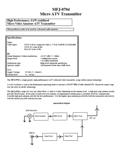
MFJ-8704Micro ATV TransmitterHigh Performance, SAW stabilizedMicro Video Amateur ATV TransmitterThis products is only to be used by a licensed radio amateurSpecifications:VideoVideo Input: NTSC or PAL composite video (1 V P-P) SMPTE STANDARDNTSC 625 Line 60 HzPAL 625 Line 50 HzRFCenter frequency without modulation 433.97 MHz +/- 50KhzOutput level: +19dBmclean carriermodulated+16.5dBmModulation type: High level amplitude modulationSpurious output: 2nd harmonic better than 40dB downVCCSupply Voltage 9V DC (+/- 300mV)Current draw 35 - 40 mAThe MFJ-8704 is a high quality, high performance SAW stabilized video transmitter, using surface mount technology.A SAW oscillator is used in the fundamental operating mode to transmit at 433.97 MHz (Cable channel 59). The power output stage uses the latest in MMIC technology.The MFJ-8704's range can vary any where from 1/4 mile to 8 miles depending on the antenna used. A high gain yagi antenna usually provides the best gain. If you plan to build your own antenna, an experimental antenna plan is included; however, commercially available high gain antennas provide the best performance. Use the highest gain antenna possible for both the transmitter and receiver with the shortest possible transmission line.Operation and SetupVideo InputThe block diagram above shows the how the MFJ-8704 needs to be connected to a video source. Make sure that you have SMPTE standard video at 1 V P-P. Most consumer and commercial cameras and camcorders deliver SMPTE standard video, at the “video out” connector. If for any reason you are not sure if the video device is delivering SMPTE standard video, you can confirm this by looking at the video signal on an oscilloscope.VCC InputDue to size limitations there is no regulation provided inside the MFJ-8704. It operates on a 9V supply. While the MFJ-8704 may tolerate about +/- 2V of VCC error, higher supply voltages may reduce the power output. A power supply could be substituted in place of a battery. Use caution in providing the proper polarity. For battery operation, best results are obtained while using nickel hydride or lithium 9V batteries. For extended operational time, you can parallel two 9V batteries. Caution: The MFJ-8704 does not include reverse polarity protection. Therefore be careful to not reverse polarity. The red power lead is (+) positive and the black power lead is (-) negative.AntennaThe transmitting and receiving antenna are probably the most critical items for attaining best range. A small piece of 1/4 wave wire as a transmitting antenna in combination with a high gain receiving antenna will work for short-range video transmission. Best results are obtained while using both high gain transmitting and receiving antennas.Range testing was performed using the following antennas. The transmit antenna was a 14 element yagi, the receiving antenna was an 8 element yagi . At an approximate distant of 3/4 of a mile excellent picture quality was received. The receiver was a consumer grade Sony TV tuned to Cable CH 59. Please remember, that while a cable ready television would suffice as a good receiver, a sensitive ATV down-converter will far outperform any cable ready television.Using a 1/4 wave ground plane (shown below) as a transmitting antenna and using a 14-element yagi antenna for the receiving antenna, excellent picture quality at 1/2 mile is possible.Experimental transmit / receive antennaSome antenna performance characteristicsWhile some transmit-receive antennas combinations perform differently, the following chart depicts the theoretical system performance of the MFJ-8704 using various combinations of antennas and an ATV down-converter.Receiver:ATV down-converter Transmitter: MFJ-8704, with a power output of 50mW Carrier/Noise: 40 – 45 dB Picture quality: Snow Free P5Antenna:Ground plane, 5 element 5L-70cm beam, 25 element DSFO ATV-25 BeamReceiving SetupAdjustment of the Video Linearity ControlThe video linearity control in the MFJ-8704 is pre-adjusted at our lab. Adjustments are not necessary unless the unit is used with an external linear power amplifier. (See Troubleshooting notes). To adjust the linearity, attach the MFJ-8704 to a video source andantenna. While observing a received picture, turn the control CCW until the picture goes black. Then turn the control in the opposite direction until the picture appears and is stable. Use the same procedure when using the MFJ-8704 with an external linear power amplifier for the first time.Troubleshooting:The MFJ-8704 provides a 50Ω antenna match. If you use anything other than 50Ω coax to feed the antenna, severe RF reflections or high SWR may occur. This could result in the unstable output from the amplifier of the MFJ-8704. Usually this will appear as a distorted receive image. Remember the MFJ-8704 is a relatively high power output device for its class. Therefore it is vital to provide good antenna matching. Supplying the MFJ-8704 with a properly matched antenna is critical!If for any reason you cannot supply a matched antenna system, where you are constrained to using a small 1/4-wave piece of wire for an antenna you may compensate for any video instability by adjusting the linearity control clockwise. This reduces the power output of the MFJ-8704, which in turn will stabilize the picture by reducing the RF energy that is reflected back to the transmitter. However, this may come at the cost of a reduced power output. Therefore, it is best to provide a good antenna system (50 ohm @ 433.97 MHz) for optimal operation of the MFJ-8704.The linearity adjustment trimmer located in the MFJ-8704 is a very critical adjustment. This control affects both the video quality as well as RF power output. The nature of an amplitude modulated video signal is such that a video signal with high contrast will result in a lower power output level while a video signal that has less contrast will provide a much higher RF power output. Adjusting the linearity control fully clockwise will result in the lowest power setting with greatest contrast. Adjusting the linearity control fully counter-clockwise will result in the highest power setting with the least contrast. In order to obtain the highest RF power output while achieving good picture, adjust the linearity control to the most counter clockwise position and then gradually turn the control in the clockwise direction until a good quality image is received. This will be the optimum video to power output position.Notice: The MFJ-8704 is an Amateur Radio ATV transmitter. The transmitter can ONLY be operated by a Technician class or higher licensed Radio Amateur in the USA and for legal purposes per 47 CFR part 97 of the FCC Rules. Section 97.113 of the FCC Rules prohibits Amateur Radio frequencies to be used to further any business purpose whether profit or non-profit. With few exceptions per 97.1 11 all transmissions must be directed to at least one other licensed Radio Amateur. Amateur Radio is intended for personal or hobby non-commercial communications between licensed Radio Amateurs. With theexception of running less than 1 watt for radio control purposes, Amateurs must identify with their call letters plainly seen in the video every 10 minutes for extended transmissions and at the end of every transmission per 97.119.LIMITED 12 MONTH WARRANTYMFJ Enterprises, Inc. warrants to the original owner of this product, if manufactured by MFJ Enterprises, Inc. and purchased from an authorized dealer or directly from MFJ Enterprises, Inc. to be free from defects in material and workmanship for a period of 12 months from date of purchase provided the following terms of this warranty are satisfied.1. The purchaser must retain the dated proof-of-purchase (bill of sale, canceled check, credit card or money order receipt, etc.)describing the product to establish the validity of the warranty claim and submit the original of machine reproduction or such proof-of-purchase to MFJ Enterprises, Inc. at the time of warranty service. MFJ Enterprises, Inc. shall have the discretion to deny warranty without dated proof-of-purchase. Any evidence of alteration, erasure, or forgery shall be cause to void any and all warranty terms immediately.2. MFJ Enterprises, Inc. agrees to repair or replace at MFJ’s option without charge to the original owner any defective product underwarranty, provided the product is returned postage prepaid to MFJ Enterprises, Inc. with a personal check, cashiers check, or money order for $7.00 covering postage and handling.3. MFJ Enterprises, Inc. will supply replacement parts free of charge for any MFJ product under warranty upon request. A datedproof-of-purchase and a $5.00 personal check, cashiers check, or money order must be provided to cover postage and handling. 4. This warranty is NOT void for owners who attempt to repair defective units. Technical consultation is available by calling (662)323-5869.5. This warranty does not apply to kits sold by or manufactured by MFJ Enterprises, Inc.6. Wired and tested PC board products are covered by this warranty provided on the wired and tested PC board product is returned.Wired and tested PC boards installed in the owner’s cabinet or connected to switches, jacks, or cables, etc. sent to MFJEnterprises, Inc. will be returned at the owner’s expense unrepaired.7. Under no circumstances is MFJ Enterprises, Inc. liable for consequential damages to person or property by the use of any MFJproducts.8. Out-of-warranty Service: MFJ Enterprises, Inc. will repair any out-of-warranty product provided the unit is shipped prepaid. Allrepaired units will be shipped COD to the owner. Repair charges will be added to the COD fee unless other arrangements are made.9. This warranty is given in lieu of any other warranty expressed or implied.10. MFJ Enterprises, Inc. reserves the right to make changes or improvements in design or manufacture without incurring anyobligation to install such changes upon any of the products previously manufactured.11. All MFJ products to be serviced in-warranty or out-of-warranty should be addressed to MFJ Enterprises, Inc., 300 Industrial ParkRoad, Starkville, Mississippi 39759, USA and must be accompanied by a letter describing the problem in detail along with a copy of your dated proof-of-purchase.12. This warranty gives you specific rights, and you may also have other rights which vary from state to state.。
Agilent N2870A探头说明书

注: * 表示保证技术指标,其他的为典型值。输入直流时,衰减比 = ± 2%,输入电阻 (只有探头,不包括 N2870A)= ± 1%
示波器输入耦合 示波器补偿范围
1 MΩ
-
1 MΩ
10-25 pF
1 MΩ
10-25 pF
1 MΩ
10-25 pF
50 Ω 1 MΩ
7-20 pF
50 Ω
-
共同点
探头 ID 读数: 兼容 Agilent InfiniiVision 和 Infiniium 系列示波器
描述 选购指南 技术资料 技术资料
出版物编号 5989-6162EN 5968-8153EN 5968-7141EN
安捷伦示波器
从 20 MHz 到>90 GHz 的多种型号 业界领先的技术指标 功能强大的应用软件
9
/find/N2870A
Agilent N2870A 系列 无源探头和附件
技术资料
简介
N2870A 系列无源探头产品树立 了带宽高达 1.5 GHz 高性能探测的新 标准。这些通用探头和附件能够以非 常合理的价格提供高质量的测量。
良好的信号可重复性
N2870A 系列无源探头提供直 流至 35 MHz、200 MHz、350 MHz、 500 MHz 和 1.5 GHz 的带宽以及各 种衰减因数,来满足广泛的测量需 求。执行通用探测时,您可以使用 N2873A 500 MHz 型号,它能够提供 卓越的 10 MΩ 输入电阻、9.5 pF 低输 入电容和低电感接地连接。这使探头 能够保持足够低的负载,以实现高信 号完整性测量。1.5 GHz 无源探头甚 至可以提供更低的输入电容,以便更 精确地测量较快边沿,从而替代相对 昂贵的有源探头。
MAX870中文资料

____________________________Features
o 5-Pin SOT23-5 Package o 99% Voltage Conversion Efficiency o Invert Input Supply Voltage o 0.7mA Quiescent Current (MAX870) o +1.4V to +5.5V Input Voltage Range o Require Only Two Capacitors o 25mA Output Current o Shutdown Control
* Dice are tested at TA = +25°C.
__________Typical Operating Circuit
__________________Pin Configuration
5
C1+
IN
2பைடு நூலகம்
INPUT SUPPLY VOLTAGE
TOP VIEW
MAX870 MAX871
元器件交易网
Switched-Capacitor Voltage Inverters
__________________________________________Typical Operating Characteristics
ABSOLUTE MAXIMUM RATINGS
IN to GND ..............................................................+6.0V to -0.3V OUT to GND ..........................................................-6.0V to +0.3V C1+ ..............................................................(VIN + 0.3V) to -0.3V C1-............................................................(VOUT - 0.3V) to +0.3V OUT Output Current ...........................................................50mA OUT Short Circuit to GND .............................................Indefinite Continuous Power Dissipation (TA = +70°C) SOT23-5 (derate 7.1mW/°C above +70°C)...................571mW Operating Temperature Range MAX870EUK/MAX871EUK ...............................-40°C to +85°C Storage Temperature Range .............................-65°C to +160°C Lead Temperature (soldering, 10sec) .............................+300°C
IV87系列说明书8711(修改)

4.1.1 定电流操作模式(CC) ............................................................................................. 9 4.1.1.1 标准定电流模式................................................................................................... 9 4.1.1.2 加载卸载定电流模式............................................................................................ 9 4.1.1.3 软启动定电流模式 ............................................................................................. 14 4.1.1.4 定电流转定电压模式.......................................................................................... 15
SD系列保护设备产品介绍说明书

The SD Series is a range of surge protection devices combining unparalleled packing densities, application versatility, proven reliable hybrid circuitry, simple installation and optional ‘loop disconnect’facilities – features which make the series the ultimate surge protection solution for process equipment, systems I/O and communications networks.The exceptionally high packing densities are the consequence of an ultra slim ‘footprint’ for individual modules which can thus ‘double-up’ as feedback terminals. Each module provides full hybrid surge protection for 2 and 3 wire loop protection.Modules with a comprehensive range of voltage ratings cover all process related signals such as RTDs, THCs, 4 to 20mA loops, telemetry outstations, shut-down systems and fire and gas detectors. Optional ‘loop disconnect’,is a feature which allows commissioning and maintenance to be carried out without removal of the surge protection device.This facility is provided by the SD07, SD16,SD32 and SD55 units. In addition, a thirdconnection on the field and safe side ofthe protector is provided in order toterminate screens safely.For three wire applications the speciallydesigned SD RTD(ResistanceTemperature Detector) and the SD32T3,(for separately powered 4-20mA loops)provide full 3-wire protection in a singlecompact unit. The recommended choicefor the protection of 3-wire pressuretransducers on low power circuits is theSD07R3.For higher bandwidth applications,theSDR series has been developed to meetthe demands of today’s highest speedcommunication systems.120V and 240V AC versionsare available for I/O andpower supplies up tothree Amps of loadcurrent.Telephone networks can be protected bythe SDPSTN.One simple manual operation clampsmodules securely onto DIN rail, whichautomatically provides the essential high-integrity earth connection.‘Top-hat’ (T-section) DIN rail is generallysuitable for mounting SD modulesalthough for adverse environments, aspecially-plated version is available fromMTL Surge Technologies. Acomprehensive range of mounting andearthing accessories can also besupplied, see page 7 for furtherdetails.Ultra-slim user-friendly devices for protecting electronic equipment and systems against surges on signal and I/O cablingSD SeriesO Range of ATEX Certified intrinsically safe surge protectorsO Ultra-slim space-saving design; easy installationO Multistage hybrid protection circuitry – 10kA maximum surge currentO Range of voltage ratings -- to suit all process I/O applicationsO High bandwidth, low resistance, RTD, PSTN and 3-wire transmitter versions availableGuide to applications and selectionAnalogue inputs(high-level)2-wire transmitters, 4-20mA, conventional and smartThe SPDs recommended for use with ‘conventional’and ‘smart’ 4-20mA transmitters(fed by a well-regulated supply) are the SD32 and SD55, the choice depending upon the maximum working voltage of the system (32V and 55V respectively). The diagram illustrates a prime example of an application for which the fuse/disconnect facility is particularly useful, however, both models are available in ‘X’versions without the optional fuse/disconnect feature.Analogue inputs(low-level)RTDsThese applications are best served using the SD RTD. F or optimum accuracy, the energising current should be chosen to ensure the voltage across the RTD does not exceed 1V over the full measurement range. When using a PT100 device, we recommend an energising current of 1mA.ac sensors, photocells, THCs, mV sources and turbine flowmetersThe SD07 or SD16 (depending upon the operational voltage) are the favoured choices for this application. SD07X and SD16X are also suitable.4561232xSD16X, SD32XPIVOVSD16 SD32 SD55SD16X SD32X SD55X (no fuse)456123SDVLogic signalOVSD07 SD16 SD32 SD55SD07X SD16X SD32X SD55X (no fuse)456123LED AlarmSD32X32V maxSD32SD32X(no fuse)IncomingtelephonelineModem,fax ortelephone456123Final output fromPLC,DCS,SCADAetc.110/120V acor220/240V acAnalogue outputsController outputs (I/P converters)F or this application, the recommendations are the SD16, SD32 and SD55 (and the equivalent ‘X’ versions), the final choice depending upon the operating voltage.Digital (on/off) inputsSwitchesSuitable SPDs for switches include the SD07, SD16, SD32 and SD55 modules – the choice depending upon the operating voltage of the system. The ‘X’ versions of these are also suitable. Digital (on/off) outputs Alarms, LEDs, solenoid valves, etcThe recommended choice for this application is the SD32 or SD32X.Telemetry (PSTN)Telemetry outstationsThe SD PSTN has been designed specifically for the protection of signals transmitted on public switched telephone networks.AC supplied equipmentPLC, I/O systemsFor systems on 110-120V ac, the SD150X is the recommended choice and for 220-240V ac systems, the SD275X is recommended.Controller outputs(I/P converters)SwitchesAlarms, LEDs,solenoid valves, etc.Telecom linePLC, I/O systemsFIELD CIRCUIT PROTECTED CIRCUIT32-wire transmitters or sensors4-20mA transmitters, conventional and smartWhere the TP48 is not an acceptable solution, either because of technical suitability or difficulties in mounting, the SD16X, SD32X and SD55X are an excellent alternative.3-wire transmitters or sensorsVibration Sensors and 4-20mA loop processcontrol systems invariably require threewire connections, when powered from anexternal source.This may be accomplished in one unit by usingthe SD32T3 three terminal Surge ProtectionDevice (SPD).Because the SD32T3 protects all threeconductors within the same unit, higherprotection is achieved, as the SPD hybridcircuitry is common to all three wires.The SD07R3 is available for the protection of 3-wire pressure transducers on low powercircuits.4-wire transmitters orsensorsFlow meters, level detectors, etc.4-wire systems such as level detectors requiretwo SDs, one for the supply and the other forthe transmitter output. Generally the voltagesacross the pairs are similar and so therecommended choice would be a pair ofSD16X, SD32X or SD55Xs. However, mainspowered transmitters should be protected withan SD150X or 275X (depending upon supplyvoltage) for the supply inputs.Loadcells are catered for by MTL SurgeTechnologies’ LC30 which is suitable for both 4and 6-wire load cells.series makes it the obvious choice for transmitter protection.The SDs within the junction box should be installed no further than one metre away but as close as possible to the sensor or transmitter they are protecting. A bond is required from the general mass of steelwork to the sensor or transmitter housing either using a flat short braid or a cable of at least 4mm2cross sectional area. In most instances this bond is automatically made by fixing the metallic transmitter housing to the plant structure. This bond ensures the voltage difference between the signal conductors and the transmitter housing is below the transmitter’s insulation rating. Please note that the transmitters or sensors are connected to the ‘Protected Equipment’ terminals of the SD and not the ‘Field Cables’.456123456123456123456123TP48SD32R (no fuse)SD32R (no fuse)SD32R (no fuse)TP48Communication systems protectionHigh speed data links between buildings or one part of a plant to another have become more common with the widespread use of smart transmitters and the increase in unmanned installations. The SD series has an SPD suitable for all process I/O applications with a choice of low resistance units, high bandwidth and a variety of voltage variants. The SDR series has been specially designed to meet the requirements for high speed data links with an extremely high bandwidth.Communication systemsRS232, RS422, RS485The recommended choice for these applications is the SD16R or SD32R depending on the maximum driver signal.Bus powered systemsThere are a variety of bus powered systems specially designed for the process industry. The ideal surge protection device for these systems is the SD32R as it has a very high bandwidth and a modest in-line resistance.Typical ApplicationsTable 1 shows suitable SD devices for different applications. In some applications alternative devices may be used, for example, where lower in-line resistance or a higher voltage power supply is used.Telematic have operationally tested therecommended SD series with representative highways listed but no formal approval for their use in systems by the respective bodies has been sought.RS232, RS422, RS485Bus powered systemsTable 1TP PROTECTED FIELD CIRCUITSD PROTECTED HOST CIRCUITPROTECTED FIELD CIRCUITSD PROTECTED HOST CIRCUITApplicationPreferred SPDAlternativeAllen Bradley Data Highway Plus SD16RFoundation Fieldbus 31.25kbits/s voltage mode SD32R 1.0/2.5 Mbits/s SD55R HART SD32X SD32, SD32R Honeywell DE SD32XSD32, SD32RLonWorks FFT-10SD32R LPT-10SD55R TP-78SD07R IS78†SD32R Modbus ‘& Modbus Plus (RS485)SD16R PROFIBUS DPSD32R PA (IEC 1158, 31.25 kbits/s)SD32R RS232SD16SD16XRS422SD07R RS423SD07R RS485SD07R WorldRP (IEC 1158)SD32R31.25 kbits/s voltage mode 1.0/2.5 Mbits/sSD55RThe SDs should be mounted on the field wiring side to ensure that any surges entering from the field do not damage any intrinsically safe barriers or galvanic isolators in the system. The SDs and IS interfaces should be mounted close to each other but on separate DIN rails in order to maintain the required 50mm clearance between safe area and hazardous area terminals.EarthingThe recommended earthing for field mounted devices has been illustrated previously but it is the earthing at the control panel that is more critical as there are usually a number of earthing systems, each with their own requirements. The earthing system illustrated here replaces the instrument 0V bond, the control system PSU bond and the IS earth with one single earth connection to meet all the design requirements and give the most effective protection against the effects of lightning induced surges.Zone 0 are considered real enough to require preventative measures. IEC 60079-14 (1996-12) Electrical apparatus for explosive gas atmospheres Part 14: Electrical installations in hazardous areas (other than mines) stresses the importance of SPDs in hazardous areas. An outdoor installation where there is a high likelihood of both lightning induced transients and combustible gases requires the installation of SPDs to prevent possible ignition of the gases. Areas seen particularly at risk include flammable liquid storage tanks, effluent treatment plants, distillation columns in petrochemical works and gas pipelines.SPDs for transmitter protection should be installed in Zone 1 but sufficiently close to the Zone 0 boundary to prevent high voltages entering Zone 0. The distance from the SPD to Zone 0 should be less than one metre where possible. However, in practice the SPD would normally be mounted on the transmitter or sensor housing which usually lies in Zone 1and is very close to Zone 0. Because there is only a very small free volume, the SD Series is suitable for mounting in flameproof or explosion proof enclosures.Zone 2The SD series is suitable for protecting electrical circuits in Division 2, Zone 2 and can be used without affecting the safety aspects of the circuit.Non-incendive (low-current) circuits can be protected using any SD series unit mounted in either the safe or hazardous area including those with the fuse disconnect facility. Non arcing (high current) circuits can also be protected except that SPDs with the fuse disconnect facility may only be mounted in the safe area. F or use in these circuits the units must be mounted in a suitable enclosure, normally the minimum requirements are IP54 and 7Nm resistance to impact. The SD series is self certified by Telematic Ltd as being suitable for this purpose.CertificationIntroducing surge protection into Intrinsically Safe (IS) circuits is trouble free as long as the current and power parameters are not exceeded. In the SD Series, the SD**X, SD**R,SD**R3, SD RTD and SD**T3 all have ATEX certification for use in IS circuits located in Zones 0, 1 or 2. The certification parameters for the SD**X and SD**T3 are:EEx ia IIC T4, Li = 0.22mH Ii = 260mA for Ui up to 20V Ii = 175mA for Ui up to 26V Ii = 140mA for Ui up to 28V Ii = 65mA for Ui up to 60VThe certification parameters for the SD**R,SD**R3 and SD RTD are:EEx ia IIC T4, Li = 0Ii = 260mA for Ui up to 60VThe power rating for each of the above is dependent on the table shown below.Pi = 1W (–30°C to +75°C)Pi = 1.2W (–30°C to +60°C) Pi = 1.3W (–30°C to +40°C) The SD** Series are classifed as simple apparatus and are intended for use in Zone 2 or safe areas only, because their fuses are not fully encapsulated.SD Series mounting kits and accessories The SD Series has a full range of mounting kits and accessories to simplify installation and tagging of individual loops. Insulating spacers (ISP7000) are available to allow mounting of the units onto backplanes without compromising correct earthing practice.These are placed at regular intervals along the rail or at each end as required. Earth connections can be made to the DIN rail via the earth terminal (ETL7000). Weatherproof enclosures are also available with all the necessary mounting accessories to install the SD series surge protection devices.Two tagging systems are available. One consists of tagging strips (TAG57) with labels (TGL57) mounted on posts (IMB57) at each end of a row of surge protection devices (SPDs). The other consists of separate tagging identifiers (BRI7000) mounted on the tops of individual SPDs. Both methods can be used conjointly. Replaceable fuses or solid links are available in packs of 5 (SD-F25, SD-F05 and SD-LNK). 7BRI700012BIL7000/BIL7000LSpecification(all figures typical at 25°C unless otherwise stated)Note: all figures are typical at +25°C unless otherwise stated; *standard fuse; +over full working temperature range; †at 20mA with a 250mA standard fuse; ‡these units need external 3A fuses; ^Signal; **Power & Common; maximum energising current depends upon RTD resistance.ProtectionFull hybrid line to lineEach line to screen/groundNominal discharge surge current (I n )10kA (8/20µs),(not applicable to SD150X and SD275X)Nominal discharge surge current (I n )6.5kA (8/20µs),(SD150X and SD275X only)Reaction time (T a )Within nanoseconds (10–9s)RTD resistance range (SD RTD )10 to 1500ΩDegradation accuracy (SD RTD at 1mA)0.1% (RTD resistance >100Ω)0.1Ω(RTD resistance < 100Ω)Ambient temperature–30°C to +75°C (working)–40°C to +80°C (storage)Humidity5 to 95% RH (non-condensing)Terminals2.5mm 2(12 AWG)MountingT-section DIN-rail(35 x 7.5 or 35 x 15mm rail)Weight70g approximately Case flammability UL94 V-2EMC complianceTo Generic Immunity Standards, EN 50082, part 2 for industrial environments R&TTE complianceEN 50082-2 : 1995EN 41003 : 1999EN 60950 : 1992(not applicable to SD150X and SD275X)LVD complianceSD150X & SD275X EN 60950 : 1992EN 61010 : 1995SD PSTNEN 41003 : 1999IEC complianceEN 61643-21:2001To order specify -Order by module, as listed in the specification table and/or accessory part numbers as defined on page 7.Note: In accordance with our policy of continuous improvement,we reserve the right to change the product’s specification without notice.Definitions of terminology used in table 1Working voltage (U n )Maximum voltage between lines or lines/ground for the specified leakage current 2Maximum leakage current (I c )Maximum current drawn by the SPD at the。
ADC0804中文资料_数据手册_参数
870说明书
技术说明书 (R1 版 Ver 1.00)
许继电气股份有限公司 XJ ELECTRIC CO.,LTD.
W**-872 微机保护测控装置
目录
1 概述.........................................................................................................................................................1 1.1 应用范围............................................................................................................................................. 1 1.2 产品特点............................................................................................................................................. 1 1.3 保护配置............................................................................................................................................. 1 2 技术指标 ..................................................................................
FDMF8704V;中文规格书,Datasheet资料

November 2007FDMF8704V High Efficiency / High Frequency FET plus Driver Multi-chip Module with Internal Voltage Regulator FDMF8704V High Efficiency / High Frequency FET plus Driver Multi-chip Module with Internal Voltage Regulator Benefits Fully optimized system efficiency. Higher efficiency levels are achievable compared with conventional discrete components. Space savings of up to 50% PCB versus discrete solutions. Higher frequency of operation. Simpler system design and board layout. Reduced time in component selection and optimization.Features 7V to 20V Input Voltage Range Output current to 32A 1MHz switching frequency capable Internal adaptive gate drive Low Side FET with Integrated Schottky Diode Peak Efficiency >90% Output disable for lost phase shutdown Integrated 5V regulator Low profile SMD package RoHS Compliant General Description The FDMF8704V is a fully optimized integrated Driver plus MOSFET power stage solution for high current synchronous buck DC-DC applications. The device integrates a driver IC and two Power MOSFETs into a space saving, MLP 8x8, 56-pin package. Fairchild Semiconductor’s integrated approach optimizes the complete switching power stage with regards to driver to FET dynamic performance, system inductance and overall solution ON resistance. Package parasitics and problematical layouts associated with conventional discrete solutions are greatly reduced. This integrated approach results in significant board space saving, therefore maximizing footprint power density. This solution is based on the Intel™ DrMOS specification.Applications Desktop and server VR11.x V-core and non V-core buck converters. CPU/GPU power train in game consoles and high end desktop systems. High-current DC-DC Point of Load (POL) converters. Networking and telecom microprocessor voltage regulators. Small form factor voltage regulator modules.Powertrain Application Circuit Figure 1. Powertrain Application Circuit Ordering Information Part Current Rating Max[A]Input Voltage Typical[V]Frequency Max[KHz]Device Marking FDMF8704V3212-191000FDMF8704V DISB PWM CGND PGND VIN BOOT VSWH DISB PWM Input C VIN7 - 20V C BOOT C OUT OUTPUT VAUX VCIN REGFB C VCIN HSEN REGOUTtm56PWM PWM Signal Input. This pin accepts a logic-level PWM signal from the controller.t PDL(HDRV)22nsf sw = 1MHz, I O = 30At PDH(LDRV)(2)12nst PDH(HDRV)(2)20nsNote 2: t PDL(LDRV/HRDV) refers to HIGH-to-LOW transition, t PDH(LDRV/HDRV) refers to LOW-to-HIGH transition.high-side gate is held low.FDMF8704V High Efficiency / High Frequency FET plus Driver Multi-chip Module with Internal Voltage RegulatorFDMF8704V High Efficiency / High Frequency FET plus Driver Multi-chip Module with Internal Voltage RegulatorDISBPWM CGNDPGNDVINVCIN VSWH DISB PWM InputC CINV CINC BOOTC OUTOUTPUTV INC VINBOOT I INAI OUT AV V OI CIN A Figure 19. Typical PCB Layout Example (Top View)HSENModule Power Loss Measurement and CalculationRefer to Figure 18 for module power loss testing method. Power loss calculation are as follows:(a) P IN = (V IN x I IN ) + (V CIN x I CIN ) (W)(b) P OUT = V O x I OUT (W)(c) P LOSS = P IN - P OUT (W)PCB Layout GuidelineFigure 19. shows a proper layout example of FDMF8704V and critical parts. All of high current flow path, such as V IN , VSWH,V OUT and GND copper, should be short and wide for better and stable current flow, heat radiation and system performance. Following is a guideline which the PCB designer should consider:1. Input bypass capacitors should be close to V IN and GND pin of FDMF8704V to help reduce input current ripple component induced by switching operation.2. It is critical that the VSWH copper has minimum area forlower switching noise emission. VSWH copper trace should also be wide enough for high current flow. Other signal routing path, such as PWM IN and BOOT signal, should be considered with care to avoid noise pickup from VSWH copper area.3. Output inductor location should be as close as possible to the FDMF8704V for lower power loss due to copper trace.4. Snubber for suppressing ringing and spiking of VSWH voltage should be placed near the FDMF8704V. The resistor and capacitor need to be of proper size for power dissipation.5. Place boot diode, ceramic bypass capacitor and boot capacitor as close to V CIN and BOOT pin of FDMF8704V in order to supply stable power. Routing width and length should also be considered6. Use multiple Vias on each copper area to interconnect each top, inner and bottom layer to help smooth current flow and heat conduction. Vias should be relatively large and of reasonable inductance.Figure 18. Power Loss Measurement Block DiagramFDMF8704V High Efficiency / High Frequency FET plus Driver Multi-chip Module with Internal Voltage Regulator分销商库存信息: FAIRCHILD FDMF8704V。
全固态电容

ADO5000IAA5DS是产品编号其中“ADO5000”代表“桌面用65W功耗双核5000+处理器”;“I”代表产品采用Socket AM2接口,“AA”代表产品支持“Cool and Quiet”技术,具备智能温控调节技术,“5”代表采用1MB L2级缓存,“DS”表示采用65纳米Brisbane核心。
封装地为马来西亚,产地为德国。
X481732A81283S 是校验码全固态电容全固态电容全称为:固态铝质电解电容。
它与普通电容(即液态铝质电解电容)最大差别在于采用了不同的介电材料,液态铝电容介电材料为电解液,而全全固态电容的介电材料则为导电性高分子。
那全全固态电容又好在哪里呢?对于经常去网吧或者长时间使用电脑的朋友,一定有过或者听过由于主板电容导致电脑不稳定,甚至于主板电容爆裂的事情!那就是因为一方面主板在长时间使用中,过热导致电解液受热膨胀,导致电容失去作用甚至由于超过沸点导致膨胀爆裂!另一方面是,如果主板在长期不通电的情形下,电解液容易与氧化铝形成化学反应,造成开机或通电时形成爆炸的现象。
但是如果采用全全固态电容,就完全没有这样的隐患和危险了!由于全全固态电容采用导电性高分子产品作为介电材料,该材料不会与氧化铝产生作用,通电后不致于发生爆炸的现象;同时它为固态产品,自然也就不存在由于受热膨胀导致爆裂的情况了。
全全固态电容具备环保、低阻抗、高低温稳定、耐高纹波及高信赖度等优越特性,是目前电解电容产品中最高阶的产品。
由于全全固态电容特性远优于液态铝电容,全全固态电容耐温达摄氏260度,且导电性、频率特性及寿命均佳,适用于低电压、高电流的应用,主要应用于数字产品如薄型DVD、投影机及工业计算机等。
电容的分类:电容就是两块导体(阳极和阴极)中间夹着一块绝缘体(介质)构成的电子元件,由于其结构的特殊性,所以分类方式也有好多种,通常按照介质、阳极、阴极和工艺这四种分类方式,而且各种分类方式互相交叉重叠,可以说比较混乱:右侧是一个简单的、并不完整的电容分类表,主要列举了一些在板卡设备上最常见的电容类型,通过这个直观的树型表可以对电容的分类、命名方式有一个直观的认识。
工控机自动化

工控机
目录
01 工控机简介
03
西门子工业计算机的 主要型号
02 西门子工控机介绍 04 西门子工控机参数
基本信息
工业控制计算机是一种采用总线结构,对生产过程及其机电设备、工艺装备进行检测与控制的设备总称。简 称“工控机”。
工控机简介
工控机简介
早在80年代初期,美国AD公司就推出了类似IPC的MAC-150工控机,随后美国IBM公司正式推出工业个人计算 机IBM7532。由于IPC的性能可靠、软件丰富、价格低廉,而在工控机中异军突起,后来居上,应用日趋广泛。现 在国内品牌主要有西门子等。
1.西门子Rack PC -采用19"设计的强大工业PC
SIMATIC rack PC系列包括采用19"设计的灵活工业PC,用于具有高性能要求的应用。西门子Rack PC拥有 一台工业PC所拥有的全部特性:采用英特尔强大处理器的创新技术,高系统可用性,坚固耐用和可扩展性,以及 长期可靠性,上市以来总的服务和支持时间为8到10年。
西门子工控机参数
西门子工控机参数
SIMATIC IPC547D概况
IPC547D配备有具有强大功能的节能型Pentium Dual Core / Corei5/Corei7处理器,内存容量达16GB, 串行ATA硬盘容量达500 GB,能够24小时连续运行,并且可靠提供极高的处理性能,而价格却极具吸引力。它的7 个扩展槽采用了PCI/PCI-Express技术,可插入功能强大的扩展板卡,如用于连接两台显示器的PCIe x16图形卡 和用于安装帧捕捉器模块的PCIe x8 (1通道)。
主要型号:SIMATIC IPC547CTIC Rack PC 647B。 2.SIMATIC Box PC——小巧通用的工业PC
870资料

050816WebSite In our continuing strategy to deliver unparalleled circuit protection solutions,technical expertise and application leadership, we proudly introduce theWICKMANN Group and its products to the Littelfuse portfolio.VDENote: 1.00 means the number one with two decimal places. 1,000 means the number one thousand.M INIA INIATURETURE F USEHOLDERS Holder / No. 870SpecificationsStandardIEC 60127-6UL 512CSA C22.2. No.39ApprovalsVDE Report SEMKOUL Recognized CSA SEVMounting12.7mm diameter D-hole or 13mm round hole Admissible torque on plastic hex nut is 1.2Nm T erminalsSolderable or 4.8mm quick connect-fits 0.5mm tab Protection Class & CategoryIP 40 (IEC 60529)PC3 (IEC 60127-6)Live parts are fully inaccessible to a 1mm diameter probeMaterialsHolder/Cap:Black Thermoplastic, UL 94V0Metal Parts:Copper alloy, corrosion protected Terminals:Solderable, tinned Electrical Data (23ºC)Rated Voltage:250V Rated Current:10ARated Power:2.5W (VDE/SEMKO)Operating T Operating Temperature emperature -40ºC to +85ºC (consider de-rating)Climatic T Climatic Testest -40ºC/+85ºC/21 days (IEC 60068-2-1...3)Stock Conditions+10ºC to +60ºCrelative humidity ≤ 75% yearly average,without dew, maximum value for 30 days - 95%V ibration Resistance24 cycles at 15 min. each (IEC 60068-2-6)10 - 60Hz at 0.35mm amplitude 60 - 500Hz at 5g acceleration Contact Resistance ≤ 5m ΩImpulse Voltage4 kV, 50 Hz, 1 min., dry Insulation Resistance> 103 M Ω (500 VDC, 1 min.)Solderability350ºC, 2 sec.Soldering Heat Resistance 350ºC, 10 sec. (IEC 60068-2-20)Minimum Cross SectionConductor - 2.5mm 2Marking870, 250V, Approvals Unit Weight5.6gPanel Mount Panel Mount, Shocksafe, Shocksafe Medical Grade, 5x20mm FusesOrder InformationPackagingBulk (100 pcs.)Order NumbersHolder and CapNo. 870 0000 100Specifications are subject to change without notice元器件交易网。
映泰TA870+详细使用手册

1.4
后置面板接口(Ver 5.0) ......................................................................4
1.5
后置面板接口(Ver 5.2) ......................................................................4
本用户手册内容的变更,恕不另行通知,制造商没有解释的义务。 本用户手册的所有内容若有任何错误,制造商没有义务为其承担任何责任。所有 商标和产品名称均有其各自所有权。 未经过书面许可,不得以任何形式(部分或全部)复制此手册信息。
免责说明
本手册内容系BIOSTAR®知识产权,版权归BIOSTAR®所有。我们本着对用户负 责的态度,精心地编写该手册,但不保证本手册的内容完全准确无误。BIOSTAR® 有权在不知会用户的前提下对产品不断地进行改良、升级及对手册内容进行修正, 实际状况请以产品实物为准。本手册为纯技术文档,无任何暗示及影射第三方之 内容,且不承担排版错误导致的用户理解歧义。本手册中所涉及的第三方注册商 标所有权归其制造商或品牌所有人。
目录
BIOS设置………………………………………………… 47 1 主菜单 ........................................................................ 49 2 高级菜单 .................................................................. 52 3 PCI PNP菜单 ............................................................. 60 4 系统引导菜单 ........................................................... 62 5 芯片组菜单............................................................... 64 6 T系列菜单 ................................................................ 70 7 退出菜单 .................................................................. 80 附:产品中有毒有害物质或元素的名称及含量.............. 83
Agilent N2870ASeries Passive Probes和辅助设备数据概述说明书

Agilent N2870A Series PassiveProbes and AccessoriesData SheetIntroductionThe N2870A Series passive probefamily sets new standards in highperformance probing of up to 1.5 GHzbandwidth. These general purposeprobes and accessories offer highquality measurements at a veryreasonable price.Faithful reproduction of signalsThe N2870A Series passive probesoffer DC to 35 MHz, 200 MHz, 350MHz, 500 MHz and 1.5 GHz band-widths and various attenuation fac-tors to address a wide range of mea-surement needs. For general purposeprobing, you can use the N2873A 500MHz model, which provides superior10 MΩ input resistance, 9.5 pF of lowinput capacitance and low-inductanceground connection. This keeps probeloading low enough to achieve highsignal integrity measurements. The 1.5 GHz passive probe offers even lower input capacitance for measur-ing faster edges more accurately, making it a low-cost alternative to an active probe.All N2870A Series probes come with the probe ID readout feature, allow-ing the probe to be automatically recognized when connected to most Agilent oscilloscopes.Figure 1. N2873A 500 MHz passive probe with standard accessories Family of 7 mini passive probes spanning from 35 MHz to 1.5 GHz • Small 2.5 mm probe tip• Replaceable spring-loaded probe tip for reliable contact• 1:1, 10:1, 20:1 and 100:1 attenuation ratios with auto probe ID readout • Wide compensation range for a variety of scope inputs• Comes with various probe tip accessories• Optional probe accessory kits• N2873A, 500 MHz, 10:1 probe ships with the 9000 Series InfiniiumoscilloscopeEasy access to signalsThe compact design with a 2.5 mmprobe tip diameter provides bettervisibility to the circuit under test thanconventional 5 mm or 3.5 mm probetips. This makes it easier to probetoday’s fine pitched space ICs andcomponents. In addition, the replace-able probe tip is spring loaded,keeping it from slipping off thedevice you are probing. All N2870ASeries probes come installed withone spring-loaded probe tip and fourspare probe tips (2 spring-loadedtips, and 2 rigid tips).Figure 2. Sharp probe tip makes it easy to probe today’s fi ne pitched components. To minimize the inductive effectsthat cause ringing of high speedsignals, use the innovative groundblade or spring ground connection.Adhesive copper pads provided withthe probe can be attached on top ofan IC and connected to its groundpins to create a convenient groundplane for the probe to connect to.When used with the ground bladethis method provides an ideal groundconnection for probing signals withhigh frequency contents.The IC caps fits over the probe tip,providing a convenient self-aligningconnection to fine-pitch IC pins.Every N2870A Series probe comeswith 5 different IC caps for IC leadpitches from 0.5 mm through1.27 mm.Figure 3. Short ground blade with copper ground plane pad provides an idealground connection for probing signals with high frequency contents. The green0.5 mm pitch IC cap fi ts over the probe tip providing a convenient self-aligningconnection to IC pins.Variety of connectionsUse the optional accessory kits toprovide access to signals and com-ponents that are difficult to probe.Figure 4. The Agilent N2885A PCB adapter sockets are designed to solder intoa printed circuit board (PCB) as test points to minimize ground inductance andmaximize signal fi delity. This package contains 25 sockets.Figure 5. Micro SMD clips were specially designed to provide fast and convenienthands-free probing of surface mount chip resistors or capacitors. This part is includedin the N2877A and N2879A accessory kits.Use the optional accessory kitsto provide access to signals andcomponents that are difficult toprobe.Figure 6. With today’s miniature IC- and component-packaging techniques, probingcan be a considerable challenge. Use 0.5 mm QFP IC clips with TQFP/PQFP packageswith 0.5 mm lead pitch or greater, or use pico-hook clips made for connections overcomponents or wires with leads up to 0.04” diameter or smaller.Figure 7. The dual lead adapter allows you to easily connect the N2870A Series probeto a popular 0.1” pin header with 0.025” square pins. This dual lead adapter has noshorting hazards since all external metal surfaces are insulated.Figure 8. An IC capadapter and groundblade with optionalN2786A two-leg probepositioner offers an idealhands-free solutionfor short circuit-proofprobing of afi ne-pitch IC. TheN2877A deluxeaccessory kit andN2878A fi ne-pitchaccessory kit containone N2786A two-legprobe positioner.Electrical characteristicsCommon to allProbe ID readout: Compatible with Agilent’s InfiniiVision and Infiniium Series oscilloscopesNote *Denotes warranted specifications, all others are typical. Attenuation ratio= ± 2% at DC, Input R (probe only, N2870A excluded)= ±1%Mechanical characteristics• Weight (probe only): 48 g• Cable length: 1.3 m• Ground sleeve diameter: 2.5 mmEnvironmental characteristicsTemperature▪ Operating: 0 °C to +50 °C▪ Non-operating: -40 °C to +70 °CAltitude• Operating: 2,000 m (6,561 ft)• Non-operating: 15,000 (49,212 ft)Humidity• Operating: 80% room humidity for temperatures upto 31 °C, decreasing linearly to 40% at 50 °CPollution degree: 2Typical voltage derating Measurement category IA m p l i t u d e A C r m s [V ]s i n u s100K1M 10M 100M 1G 10Frequency [Hz]Figure 9. N2870A Series amplitude vs. frequency characteristicsTypical input impedance│Z │[o h m ]Frequency [Hz]100M 10M 1M100K 10K 1K 10010101001K10K100K1M10M100M1G10GFigure 10. N2870A Series input impedance vs. frequency characteristicsStandard accessoriesOptional accessoriesOptional accessories(continued)Note: For the exact number of accessories that come with each of the accessory kits, referto the N2870A Series probes and accessories user’s guide with Agilent literature numberN2876-97000.Agilent 5000, 6000 and 7000 Series InfiniiVision Oscilloscope Probes, Accessories and optionsData sheet 5968-8153EN Agilent Infiniium Oscilloscope Probes, Accessories and optionsData sheet5968-7141ENRelated LiteratureAgilent Technologies OscilloscopesMultiple form factors from 20 MHz to >90 GHz | Industry leading specs |Powerful applications0960-2905 Sprung Hook Adapter 2.5mm for N2870A,71A,72A,73A,75A 0960-2906Ground Lead 15cm for N2870A Series probes0960-2907Short Spring Hook 2.5mm for N2874A and N2876A 1.5 GHz passive probe 0960-290810 Self-adhesive Copper-pads 2X2cm for N2870A Series probes 0960-2898Dual Lead-Adapter for N2870A Series probesReplacement PartsMicrosoft is a U.S. registered trademark ofMicrosoft Corporation.Product specifi cations and descriptions in this document subject to change without notice.Product specifications and descriptions in this document subject to change without notice.October 1, 2009© Agilent Technologies, Inc. 2010Printed in USA, January 29, 20105990-3930EN。
NEC VC-870 VD-870 半机柜大小的硬件编码器说明书
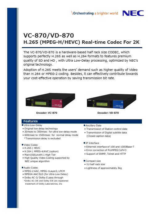
The VC-870/VD-870 is a hardware-based half rack size CODEC, which supports perfectly H.265 as well as H.264 formats to features premiumquality of SD and HD , with Ultra Low-Delay processing, optimized by NEC’s original technology.Adoption of H.265 meets the users’ demand such as higher quality of Video than H.264 or MPEG-2 coding. Besides, it can effectively contribute towards your cost-effective operation by saving transmission bit rate.n Ultra Low-Delay• Original low delay technology• 20msec to 300msec for ultra low-delay mode • 600msec to 1500msec for normal delay mode *Transmission delay is excluded n Video Codec • H.265 | HEVC• H.264 | MPEG-4/AVC (option)• Main10@Level4.1 High Tier• High Quality Video Coding supported by NEC unique algorithm n Audio Codec• MPEG-2 AAC, MPEG-1Layer2, LPCM • MPEG4-AAC ELD (for Ultra Low Delay)• Dolby AC-3/ Dolby E pass through*Dolby AC-3® and Dolby-E® are registered trademark of Dolby Laboratories, Incn Ancillary Data• Transmission of Station control data • Transmission of Digital subtitle data (Closed caption data)n IP Interface• Ethernet interface of 100 and 1000Base-T • Error correction of ProMPEG CoP#3• Support of SNMP, Telnet and HTTPn Compact size • 1U half rack size• Lightness of approximately 3kgVC-870/VD-870H.265 (MPEG-H/HEVC) Real-time Codec For 2KEncoder: VC-870Decoder: VD-870VC-870/VD-870 H.265 (MPEG-H/HEVC) Real-time Codec for 2KSpecificationEncoder VC-870Decoder VD-870Input signal Output signal(1) Encoder Input Signal/Decoder Output Signal ■1080p serial digital component videoStandard: SMPTE-274M, I/F: SMPTE-292M, Frame freq.: 59.94/50Hz, Interlace ratio: 1:1■1080i serial digital component videoStandard: ITU-R BT.709, I/F: SMPTE-259M, Frame freq.: 59.94/50Hz, Interlace ratio: 1:1■480i/512i serial digital component videoStandard: ITU-R BT.601, I/F: SMPTE-259M, Frame freq.:29.97, Interlace ratio: 2:1■576i/608i serial digital component videoFrame freq.:25Hz, Interlace ratio: 2:1■Audio formatEmbedded Audio (16ch) / AES/EBU (8ch)(2) Encoder Output Signal/Decoder Input Signal■MPEG-2 TS (Transport Stream), I/F:DVB-ASI,Ethernet 100/1000/Base-TFormat:(204,188) or (188), Mode:byte or packet mode (3) Encoder External TS Clock input ■Maximum: 160MHzVideo codec(1)H.265(HEVC)*****************,*******************Max. rate 60MbpsChroma 4:2:0 / 4:2:2 Bit depth:8bit / 10bitGOP structure:I-Only, Intra Slice, Long GOP(2)************************@L4.0,*********,*********,*********(option)Max. rate 160Mbps Chroma 4:2:0 / 4:2:2Bit depth:8bit / 10bitGOP structure:I-Only, Intra Slice, Long GOP(3) MPEG-2422P@HL,MP@HL,MP@H14L,SP@HL,SP@H14L, 422P@ML,MP@ML,SP@ML Max. rate 120Mbps Chroma 4:2:0 / 4:2:2GOP structure:I-Only, Intra Slice, Long GOPAudio codec MPEG-2 AAC-LC profile, MPEG-4 AAC-ELD, MPEG-1-Layer2, LPCM(SMPTE302M-2002) Ancillary ARIB TR-B22, ARIB TR-B23, ITU-R BT. 1366Delay ・Low delay mode:20ms〜300ms・Normal delay mode:600ms~1500ms Reference N/ASMPTE170M,ITU-R BT.709-4Network I/F : Ethernet 100/1000Base-T Protocol : Unicast, Multicast Transport : MPEG-2 TS over RTP/UDP/IP FEC: Pro-MPEG CoP#3ControlI/F : Ethernet 10/100Base-TX Protocol : SNMP, HTTP Operation temperature 0℃〜50℃Power Supply AC85〜264V, 50/60Hz Power Consumption 50VA or lessDimensions / Weight210(W)×400(D)×44(H)mm/3kgFor additional information: Please contact your nearest NEC sales officesTo install, make connections and operate this product, please carefully read and observe instructions,precautions and recommendations in our instruction manuals.Safety precautions●The colours in this brochure may differ from those of the actual unit. Designs and specifications of this product is subject to change without prior notice.© 2015 NEC Corporation. NEC and the NEC logo are registered trademarks of NEC Corporation.NEC CorporationAmericas and Platform Solutions Division Europe, the Middle East and Africa Division Greater China and Asia Pacific Division7-1, Shiba 5-chome, Minato-ku, Tokyo, 108-8001, JapanTel: +81-3-3798-5463 Fax: +81-3-3798-6359/global/prod/nw/broadcast/NEC Asia Pacific Pte. Ltd.80 Bendemeer Road,#05-01/02, Hyflux Innovation Centre, Singapore 339949Tel: +65-6273-8333Fax: +65-6271-2088NEC Latin America S.A.Avenida Angelica 2197 -10th Floor -01227-200-Sao Paulo -SP-Brazil Tel: +55-11-3151-7000Fax:+55-11-3151-7199NEC Europe Ltd.Athene, Odyssey Business Park West End Road, South Ruislip,Middlesex HA4 6QE, United Kingdom Tel: +44-20-8836-2000Fax: +44-20-8836-2001!H99-15080005EJMI-0119JQA-E-90066ISO 14001ISO 9001ISO/IEC 27001JQA-IM1064。
- 1、下载文档前请自行甄别文档内容的完整性,平台不提供额外的编辑、内容补充、找答案等附加服务。
- 2、"仅部分预览"的文档,不可在线预览部分如存在完整性等问题,可反馈申请退款(可完整预览的文档不适用该条件!)。
- 3、如文档侵犯您的权益,请联系客服反馈,我们会尽快为您处理(人工客服工作时间:9:00-18:30)。
fS =
6500 (kHz) ,其中,RRI 为外接电阻值,单位是 KΩ。 RRI
电流检测和前沿消隐 在 MOSFET 开启的时刻,由于缓冲电路中的二极管反向恢复会产生的电流毛刺。该毛刺会影 响 PWM 比较器的误判,必须去除。芯片中 SENSE 端内置的前沿消隐电路实现这一功能,原先需 要的外围 RC 滤波电路则可以省去。 在前沿消隐时间内,PWM 比较器和限流比较器是不工作的,MOSFET 开关在这段时间内是 保持导通状态的。所以,MOSFET 开关开启的最小时间就是前沿消隐的时间。 栅驱动 GATE 管脚连接到外部 MOSFET 的栅,来实现对 MOSFET 的开关控制。GATE 的驱动能力 太弱,MOSFET 的开关损耗会增加;反之,GATE 的驱动能力太强,则会带来 EMI 问题。因此, 芯片的图腾柱式的驱动输出部分在驱动能力和死区时间之间进行了折衷。 GATE 的输出高电平被钳位在 13V,以保护外部 MOSFET 的安全。 保护功能 芯片自带各种保护功能,包括每周期的过流保护、过载保护、输入电压的过压及欠压保护 等。 通过输入电压补偿的过流保护阈值电压,实现输出的恒功率控制。 VDD 由外部变压器的辅助绕组输出供电。当 VDD 电压过高时,被钳位在阈值处;当 VDD 电压 过低时,MOSFET 开关截止,系统重新进入上电复位过程。 当 FB 电压超过过载保护电压阈值,且维持时间达到时,MOSFET 开关截止,VDD 电压开始 下降,当 VDD 低于 UVLO 阈值后,重新复位启动。
无铅 无铅 无铅 无铅
杭州士兰微电子股份有限公司
Http:
版本号:1.2
2010.08.17 共8页 第1页
SD4870
内部框图
极限参数
参 电源电压 反馈电压 采样端电压 RI 端电压 结温 引脚温度 存储温度 数 符 号 VDD VFB VSENSE VRI Tj TL Tstg 参 数 范 围 25 -0.3~6 -0.3~6 -0.3~6 -20~150 260 -55~160 单位 V V V V °C °C °C
杭州士兰微电子股份有限公司
Http:
版本号:1.2
2010.08.17 共8页 第3页
SD4870
管脚排列图
管脚描述
管 脚 号 SD4870 1 2 3 4 5 6 -SD4870A SD4870C 8 7 5 4 2 1 3,6 GND FB RI SENSE VDD GATE NC -I I/O I -O -地。 反馈输入端。 振荡频率设置端。外接电阻到地。 开关电流采样端。 电源。 栅驱动输出。 空脚。 管脚名称 I/O 管 脚 描述
2010.08.17 共8页 第7页
SD4870
封装外形图
SOT-23-6L UNIT: mm
MOS电路操作注意事项:
静电在很多地方都会产生,采取下面的预防措施,可以有效防止MOS电路由于受静电放电影 响而引起的损坏: • 操作人员要通过防静电腕带接地。 • 设备外壳必须接地。 • 装配过程中使用的工具必须接地。 • 必须采用导体包装或抗静电材料包装或运输。
2010.08.17 共8页 第6页
SD4870
封装外形图
DIP-8-300-2.54 UNIT: mm
SOP-8-225-1.27
UNIT: mm
3.9±0.3
杭州士兰微电子股份有限公司
Http: 1.55±0.源自00.3~1.27版本号:1.2
5.72±0.3
6.0±0.4
SD4870
电流模式PWM控制器
描述
SD4870 是电流模式 PWM控制芯片。用于高性能、低 待机功耗的离线反激变换器的控制。 在空载或轻载时,芯片工作在轻载模式,减小开关损 耗,提高效率。 芯片的低启动电流,使得启动电路可以采用阻值大的 启动电阻,来减小待机电流。 自带各种保护功能,包括每周期的过流保护、过载保 护、VDD电压的过压及欠压保护等。 抖频工作技术以及带软开关控制的图腾柱式驱动输出 可以达到极佳的EMI性能。
应用
* 电池充电器 * 适配器 * 机顶盒电源
产品规格分类
产 品 名 称 SD4870TR SD4870A SD4870C SD4870CTR 封 装 形 式 SOT-23-6L DIP-8-300-2.54 SOP-8-225-1.27 SOP-8-225-1.27 打 印 名 称 4870 SD4870A SD4870C SD4870C 材 料 包 装 编带 料管 料管 编带
DIP-8-300-2.54 SOP-8-225-1.27 SOT-23-6L
主要特点
* 开关的抖频控制提高 EMI 性能 * 轻负载模式减小待机功耗 * 外部设置开关频率 * 3μA 低启动电流 * 内置前沿消隐电路 * VDD 电压的过压及欠压保护 * 栅驱动输出高电压钳位 * 电流限制 * 过负载保护 * SOT-23-6L/SOP8/DIP8 封装形式
功能描述
SD4870 是电流模式的 PWM 控制芯片,应用于离线式反激变换器的应用。以下是对芯片各功 能的具体描述。 启动控制 SD4870 的启动电流很低,因此可以快速启动。外部启动电路可以采用较大的启动电阻,在保 证启动正常的同时减小待机功耗。 在输入电压范围之内,可以采用 2 MΩ,1/8 W 的启动电阻。 抖频控制 芯片采用抖频控制来改善 EMI 性能。 振荡频率随机调制后,基频的能量被扩展到一个窄频带中,从而减小基频处的电磁干扰。整 个应用系统的设计会变得更简单。
杭州士兰微电子股份有限公司
Http:
版本号:1.2
2010.08.17 共8页 第2页
SD4870
电气参数(除非特别说明,Tamb=25°C)
参 电源电压 启动电流 工作电流 欠压锁定阈值电压 欠压锁定迟滞电压 VDD 钳位电压 反馈电压 PWM 增益 FB 开环电压 FB 短路电流 过载保护 FB 阈值 过载保护抗干扰时间 FB 输入阻抗 最大占空比 电流检测 LEB 时间 SENSE 输入阻抗 过流检测控制延时 过流检测阈值 振荡频率 振荡频率 振荡频率随 VDD 而 变化 RI 外接电阻范围 轻载模式的振荡频率 抖频范围 GATE 驱动 输出低电平 输出高电平 高电平高钳位电压 输出上升时间 输出下降时间 VOL VOH VOH_CLAMP TR TF VDD=16V,CL=1nF VDD=16V,CL=1nF VDD=16V,IO=-20mA VDD=16V,IO=20mA -10 -----13 220 70 0.8 ----V V V ns ns fS ΔfS_VDD RRI_RANGE fS_LLM ΔfS_SHUF RI=100kΩ RI=100kΩ VDD=12~25V, RI=100kΩ 60 -50 --3 65 5 100 22 -70 -150 -3 kHz % kΩ KHz % TLEB ZSENSE_IN TOC VSENSE_OC RI=100kΩ ---0.7 300 85 75 0.75 ---0.8 ns kΩ ns V AVCS VFB_OPEN IFB_SHORT VFB_OL TD_OL ZFB_IN DMAX VDD=16V,RI=100kΩ VFB =3V,VSENSE =0V FB 短接到地 ΔVFB /ΔVSENSE -4.5 0.8 --4 -2 4.8 1 3.8 35 6 75 -5 1.2 ----V/V V mA V ms kΩ % IVDD_ST IVDD VUVLO VUVLOH VVDD_CLP IVDD =10mA VDD=12 V,RI=100kΩ VDD=16V , VFB =3V , RI=100kΩ --13.3 --3 2 14.3 6.3 21.5 20 -15.3 --μA mA V V V 数 符 号 测 试 条 件 最小值 典型值 最大值 单位
杭州士兰微电子股份有限公司
Http:
版本号:1.2
2010.08.17 共8页 第8页
声明: • •
•
士兰保留说明书的更改权,恕不另行通知!客户在下单前应获取最新版本资料,并验证相关信息是否 完整和最新。 任何半导体产品特定条件下都有一定的失效或发生故障的可能,买方有责任在使用 Silan 产品进行系 统设计和整机制造时遵守安全标准并采取安全措施,以避免潜在失败风险可能造成人身伤害或财产损 失情况的发生! 产品提升永无止境,我公司将竭诚为客户提供更优秀的产品!
杭州士兰微电子股份有限公司
Http:
版本号:1.2
2010.08.17 共8页 第5页
SD4870
典型应用电路图
AC in
DC out
VDD GATE SENSE RI
SD4870
FB GND
杭州士兰微电子股份有限公司
Http:
版本号:1.2
杭州士兰微电子股份有限公司
Http:
版本号:1.2
2010.08.17 共8页 第4页
SD4870
轻负载模式 在轻负载或空载条件下,MOSFET 的开关损耗、变压器的损耗以及外部 snubber 电路的损耗 占总功耗的很大一部分。而以上这些损耗正比与单位时间内的开关次数。所以减小单位时间内的 开关次数将直接降低以上损耗。 SD4870 在轻负载或空载时刻进入轻负载工作模式。只有当输出电压降低到设定设定值时, MOSFET 才开始开关工作,同时,开关频率也降低。否则,MOSFET 一直截至。 振荡频率设置 振荡由 RI 和 GND 之间的外接电阻值决定,两者之间的关系如下公式所示。